EP4039307A1 - A foam-based interfacing structure - Google Patents
A foam-based interfacing structure Download PDFInfo
- Publication number
- EP4039307A1 EP4039307A1 EP21217202.7A EP21217202A EP4039307A1 EP 4039307 A1 EP4039307 A1 EP 4039307A1 EP 21217202 A EP21217202 A EP 21217202A EP 4039307 A1 EP4039307 A1 EP 4039307A1
- Authority
- EP
- European Patent Office
- Prior art keywords
- foam
- clip portion
- cushion
- cushioning component
- mask
- Prior art date
- Legal status (The legal status is an assumption and is not a legal conclusion. Google has not performed a legal analysis and makes no representation as to the accuracy of the status listed.)
- Pending
Links
Images


Classifications
-
- A—HUMAN NECESSITIES
- A61—MEDICAL OR VETERINARY SCIENCE; HYGIENE
- A61M—DEVICES FOR INTRODUCING MEDIA INTO, OR ONTO, THE BODY; DEVICES FOR TRANSDUCING BODY MEDIA OR FOR TAKING MEDIA FROM THE BODY; DEVICES FOR PRODUCING OR ENDING SLEEP OR STUPOR
- A61M16/00—Devices for influencing the respiratory system of patients by gas treatment, e.g. mouth-to-mouth respiration; Tracheal tubes
- A61M16/06—Respiratory or anaesthetic masks
- A61M16/0605—Means for improving the adaptation of the mask to the patient
- A61M16/0616—Means for improving the adaptation of the mask to the patient with face sealing means comprising a flap or membrane projecting inwards, such that sealing increases with increasing inhalation gas pressure
- A61M16/0622—Means for improving the adaptation of the mask to the patient with face sealing means comprising a flap or membrane projecting inwards, such that sealing increases with increasing inhalation gas pressure having an underlying cushion
-
- A—HUMAN NECESSITIES
- A61—MEDICAL OR VETERINARY SCIENCE; HYGIENE
- A61M—DEVICES FOR INTRODUCING MEDIA INTO, OR ONTO, THE BODY; DEVICES FOR TRANSDUCING BODY MEDIA OR FOR TAKING MEDIA FROM THE BODY; DEVICES FOR PRODUCING OR ENDING SLEEP OR STUPOR
- A61M16/00—Devices for influencing the respiratory system of patients by gas treatment, e.g. mouth-to-mouth respiration; Tracheal tubes
- A61M16/06—Respiratory or anaesthetic masks
- A61M16/0605—Means for improving the adaptation of the mask to the patient
-
- A—HUMAN NECESSITIES
- A61—MEDICAL OR VETERINARY SCIENCE; HYGIENE
- A61M—DEVICES FOR INTRODUCING MEDIA INTO, OR ONTO, THE BODY; DEVICES FOR TRANSDUCING BODY MEDIA OR FOR TAKING MEDIA FROM THE BODY; DEVICES FOR PRODUCING OR ENDING SLEEP OR STUPOR
- A61M16/00—Devices for influencing the respiratory system of patients by gas treatment, e.g. mouth-to-mouth respiration; Tracheal tubes
- A61M16/06—Respiratory or anaesthetic masks
- A61M16/0683—Holding devices therefor
- A61M16/0688—Holding devices therefor by means of an adhesive
-
- A—HUMAN NECESSITIES
- A61—MEDICAL OR VETERINARY SCIENCE; HYGIENE
- A61M—DEVICES FOR INTRODUCING MEDIA INTO, OR ONTO, THE BODY; DEVICES FOR TRANSDUCING BODY MEDIA OR FOR TAKING MEDIA FROM THE BODY; DEVICES FOR PRODUCING OR ENDING SLEEP OR STUPOR
- A61M16/00—Devices for influencing the respiratory system of patients by gas treatment, e.g. mouth-to-mouth respiration; Tracheal tubes
- A61M16/06—Respiratory or anaesthetic masks
- A61M16/0605—Means for improving the adaptation of the mask to the patient
- A61M16/0633—Means for improving the adaptation of the mask to the patient with forehead support
-
- A—HUMAN NECESSITIES
- A61—MEDICAL OR VETERINARY SCIENCE; HYGIENE
- A61M—DEVICES FOR INTRODUCING MEDIA INTO, OR ONTO, THE BODY; DEVICES FOR TRANSDUCING BODY MEDIA OR FOR TAKING MEDIA FROM THE BODY; DEVICES FOR PRODUCING OR ENDING SLEEP OR STUPOR
- A61M2207/00—Methods of manufacture, assembly or production
- A61M2207/10—Device therefor
-
- A—HUMAN NECESSITIES
- A61—MEDICAL OR VETERINARY SCIENCE; HYGIENE
- A61M—DEVICES FOR INTRODUCING MEDIA INTO, OR ONTO, THE BODY; DEVICES FOR TRANSDUCING BODY MEDIA OR FOR TAKING MEDIA FROM THE BODY; DEVICES FOR PRODUCING OR ENDING SLEEP OR STUPOR
- A61M2209/00—Ancillary equipment
- A61M2209/02—Equipment for testing the apparatus
Definitions
- the present invention relates to an interface between a human and a piece of equipment, for example respiratory devices that include a foam-based interfacing structure,
- apparatus for delivery of therapy includes a rigid component and a soft, cushioning component positioned between a patient and the rigid component.
- the rigid component may be a mask frame defining a nose and/or mouth-receiving chamber.
- the mask frame may include a flange around its periphery or other connecting means.
- the cushioning component may be glued or otherwise coupled to the flange or connecting means.
- the cushioning component may form aa seal with the skin of the patient in some forms of respiratory therapy.
- aa seal may not be necessary for aa seal to be formed,
- a first aspect of the invention is to provide a mask assembly with a foam interfacing structure
- Another aspect of the invention is to provide a mask assembly with a foam interfacing structure where at least a part of the foam (e.g., an unskinned part of the foam) is in direct contact with the skin of the mask user.
- a part of the foam e.g., an unskinned part of the foam
- Another aspect of the invention is to provide a mask assembly with a foam interfacing structure where the foam is unskinned and has a cellular structure of the foam in direct contact with, the skin of the mask user.
- Another aspect of the invention is to provide a mask assembly with a removable foam interfacing structure.
- Another aspect of the invention is to provide a mask assembly with at least two different types of removably replaceable interfacing structures.
- Another aspect of the invention is to include a softer interfacing structure having portion adapted for engagement with a more rigid component,
- Another aspect of the invention is to provide a respiratory mask assembly including a frame and an interfacing structure wherein the interfacing structure includes a foam-based cushion component and a clip portion adapted for removable engagement with the frame portion.
- Another aspect of the invention is to provide a support structure for a cushioning component wherein the support structure supports the cushioning element on one side and allows movement on another side.
- a cushion for a respiratory mask including a clip portion and a cushioning component wherein the cushioning component is constructed from a foam material and the clip portion is narrower than the cushioning component
- a respiratory mask assembly including a frame having a channel and an interfacing structure including a clip portion adapted for interference seal and retention in the channel.
- the interfacing structure includes a cushion component constructed from foam and having a wider width than the clip portion.
- Another aspect is a foam-based cushioning component preferably having a first cross-section in a nasal bridge region, a second cross-section in a lip region and a third cross-section in the cheek region.
- Another aspect is a method of manufacturing a cushioning component, e.g., die cutting and/or machining, etc.
- Another aspect is a method of insert molding a clip component to a cushioning component to form an interfacing structure.
- a cushioning component for use with a mask, wherein the cushioning component is constructed of foam material.
- a patient contacting surface that is adapted to contact a patient, in use, may have a rounded cross sectional profile and a base surface opposed to the patient contacting surface.
- a removable interfacing structure for use with a mask including a cushioning component constructed of foam material wherein a patient contacting surface that is adapted to contact a patient, in use, has a rounded cross sectional profile and a base surface opposed to the patient contacting surface is joined to a clip portion, and wherein the clip portion is adapted to be removably joined to a frame of the mask.
- a mask including a removable interfacing structure and a frame
- the interfacing structure includes a clip portion and a cushioning component constructed of foam material having a patient contacting surface that is adapted to contact a patient, in use, has a rounded cross sectional profile and a base surface opposed to the patient contacting surface is joined to the clip portion, and wherein the clip portion is adapted to be removably joined to a frame of the mask.
- Another aspect is a mask including a frame and an interfacing structure, wherein the interfacing structure includes a clip portion joined to cushioning component, and wherein the frame is more rigid than the clip portion and the clip portion is more rigid than the cushioning portion.
- Another aspect is a cushioning component for use with a mask, wherein at least a portion of the cross section of the cushioning component includes an inner side defined by the side facing the centre of the mask, an outer side defined by a side facing away from the centre of the mask and a base side facing the frame or clip portion, wherein the length of outer side is greater than the inner side.
- Another aspect is an interfacing structure for a mask including a clip portion joined to a cushioning component, wherein an upper surface of the clip portion is joined to a base surface of the cushioning component and wherein at least a portion of the upper surface is angled to provide a moment force on cushioning component, when force is applied into the cushioning component.
- Another aspect is an interfacing structure for a mask including a clip portion joined to a cushioning component, wherein an upper surface of the clip portion is joined to a base surface of the cushioning component and wherein the cross sectional width of the clip portion is less than the cross sectional width of the cushioning component.
- a cushioning component for use with a mask, wherein at least a portion of the cross section of the cushioning component includes an inner side defined by the side facing the centre of the mask, an outer side defined by a side facing away from the centre of the mask and a base side facing the frame or clip portion, wherein the outer side further includes at least an upper and a lower portion, wherein the upper portion is positioned at a reduced angle in comparison to the lower portion.
- a nasal mask including a frame removably connected to an interfacing structure, wherein the interfacing structure includes a cushioning component constructed of foam material, and wherein the height of the interfacing structure is reduced in relation to region that is adapted to contact the upper lip region of a patient's face,
- a respiratory mask including a frame, a foam cushion and a substructure.
- the mask includes a nose receiving cavity.
- the cushion includes at least two sides: an inner side wall, which may be a wall at least partially facing the cavity; and an outer side wall.
- the foam cushion is soft and conforming.
- the substructure is constructed from a more rigid material.
- the foam cushion is adapted to form a seal with at least one region of a face of a patient. In use the foam cushion is supported by the substructure.
- a connecting surface of the substructure is defined.
- a patient side of the foam cushion is defined.
- a non-patient side of the cushion is defined. In use the non-patient side of the cushion is arranged adjacent the connecting surface of the substructure.
- the foam cushion is glued to the substructure.
- the foam cushion is insert moulded with the substructure.
- a first region of the face is defined as a comer of the mouth of the patient.
- a second region of the face is defined as a chin region, or alternatively a lip region of the face of the patient.
- An interior region of the cushion is defined as the region or cavity into which a nose of a patient is inserted in use.
- a part of the connecting surface in use adjacent the first region is structured in to direct a corresponding portion of the foam cushion in an inward direction towards the interior region of the cushion in the first region in use.
- the cross-section of the cushion defines a radial axis and a longitudinal axis is normal to said radial axis.
- at least a portion of the foam cushion is adapted to rotate towards the centre of the mask about said longitudinal axis when pressure is applied into the cushion by the patient's face and wherein at least a portion of the outer side wall of said cushion is adapted to form a seal against the face of a patient.
- portions of the cushion rotate or roll inwards towards the centre of the mask.
- the feature of rolling or rotating inwards may prevent or limits the possibility of the seal "blowing out” when air pressure is applied to the mask cavity "Blowing out” is defined by the seal between the cushion and the patient's face breaking due to pressure exerted by air pressure lifting the cushion from a sealing relationship with the face.
- a part of the connecting surface in use adjacent the second region is structured to direct the foam in an outward direction away from the interior region of the cushion in the second region in use.
- the cross-section of the cushion defines a radial axis and a longitudinal axis is normal to said radial axis.
- at least a portion of the foam cushion is adapted to rotate away from the centre of the mask about said longitudinal axis when pressure is applied into the cushion by the patient's face and wherein at least a portion of the outer side wall of said cushion is adapted to form a seal against the face of a patient.
- further portions of the cushion may rotate inwards or outwards relative to the centre of the mask in positions defined as being proximal to the patient's chin.
- this rotation may allow for seal to accommodate different sizes of chin and/or accommodate moderate amounts of mouth or jaw movement that may otherwise destruct the seal formed between the mask and the patient's face.
- Another aspect of the present technology is a foam cushion for a respiratory mask wherein the cushion includes a face-contacting portion arranged in use to be adjacent the face of the patient.
- a cross section of the cushion tapers from a wider cross-section to a narrower doss-section closer to the face.
- the tapered portion defines an inside surface adjacent an interior of the cushion and an outside surface.
- the inside surface and the outside surface may be adjacent, in another form they may be non-adjacent.
- the inside and outside surfaces may be arranged at an acute angle with respect to one another.
- the outside surface is longer than the inside surface in certain regions of the cushion, preferably in the nasal bridge region, or in the cheek region, or more preferably in both.
- the inside and outside surfaces have the same length in a chin region.
- the inside surface is longer than the outside surface in cross-section.
- the cushion is structured to at least partially form a seal on an outside surface of a face in a chin region of the cushion.
- a tapered sealing portion may improve the seal.
- air will be taken to include breathable gases, for example air with supplemental oxygen,
- seal will be taken to mean to reduce the flow of air between the pressurized interior of the mask and the ambient conditions to a level sufficient to maintain a therapeutic pressure in the airways to effect treatment. Hence in some cases, there may be an air tight seal, in other cases there may be a small leak.
- a mask assembly used to facilitate the delivery of a supply of air or breathable gas to the entrance of the airways of a patient typically includes a generally soft, conforming interfacing structure, at least a portion of which is in contact with the patient's face and a stabilizing structure that positions and retains the interfacing structure in a suitable position with respect to the patient.
- the mask assembly typically includes some form of anchor point to which various components may be connected, or about which they may be arranged, In this specification, this anchor point will be referred to as the frame.
- the stabilizing structure of the mask assembly may be called "headgear" and both the headgear and interfacing structure may be connected to a frame.
- the boundary lines between the different components may be blurred.
- aspects of frame and headgear may be combined.
- the interfacing structure may perform two or more functions: (i) a cushioning function, performed by a cushioning component, and (ii) an interconnection function, performed by a cushion-to-frame component or clip portion.
- a cushioning function performed by a cushioning component
- an interconnection function performed by a cushion-to-frame component or clip portion.
- clip or “clip portion” may describe the aforementioned clip portion or a cushion to frame component for securing the cushioning component to a frame of a mask.
- Forming the interfacing structure from two separate elements enables each to have different properties, such as different densities or air permeabilities as suits their different roles, as will be described in more detail in the following sections.
- the different properties of different materials can act to influence the other component. For example, a more rigid clip or cushion-to-fraine portion can act as a support structure for a softer cushioning component.
- the interfacing structure may be constructed from a single component with different properties in different regions of the interfacing structure.
- the interfacing structure may be formed from more than two components.
- the interfacing structure may be constructed and arranged to apply air or breathable gas to both the nose and mouth (a "nose & mouth” or “full-face” mask), or to the just the nose (a "nose” or “nasal” mask), or just the mouth (a "mouth” mask).
- the cushioning component may be made from an unskinned, low density, permeable foam.
- the cushion component is constructed from a low resilience viscoelastic polyurethane foam.
- the cushioning component material may be manufactured from a free rising slabstock foam process, In other embodiments the material may be manufactured by other processes such as molding or other known processes used to produce soft and cellular materials.
- One or more fabrication steps may then be applied to the material to partially or completely form the geometry of the cushion component. These conversion techniques are described herein and in other related specifications referenced herein. Such a foam material and conversion techniques are disclosed in PCT Publication Nos.
- the cushioning component may be formed in whole or in part by a known method such as die cutting. Die cutting is disclosed in PCT Application PCT/AU2009/000262, filed March 4, 2009 . In another form the cushioning component may be formed in whole or in part by using other methods such as those disclosed in AU 2008904769 and AU 2008904778 .
- foam material production techniques produce a material that has a substantially skinned material such that the density of the material at the surface is greater than the density of the material's bulk (internal) properties.
- the utilization of particular manufacturing techniques, such as foam conversion processes involving cutting, may allow the production of a unskinned cushioning component such that the bulk properties of the cellular material are exposed at the surface of the cushioning component, providing a number of advantages to the design, manufacture and performance of the mask assembly.
- the unskinned cushion component provides improved sealing, comfort and fit range performance, sealing properties sufficient to not require a silicone membrane, and a unskinned mask assembly that allows utilization of the bulk properties of the unskinned material, e.g., porosity for breathability, fine cell structure for a comfortable feel.
- the interfacing structure is preferably constructed and arranged to have a three dimensional shape defined in part by a locus of points surrounding and complementary to the entrance to the relevant airways, Furthermore, the interfacing structure has a cross-section chosen at different points around its perimeter to provide efficacy and comfort by being suitably shaped to adapt and conform to the face of the user forming a compression-type seal. In another configuration, a flap-type seal is formed.
- the shape of the interfacing structure may be adapted to allow the cushioning component to provide a better fit and seal against the face of the patient.
- the geometry of the cushion may be at least partly determined by the geometry of the frame to which it is to be attached.
- the general shape of a small size cushion may be different than the general shape of a large size cushion because the small and large size frames may be different, e.g., the small may be more stout or wide while the large may be more elongated and thinner.
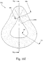
- Figs. 16g to 16i show various cross-sections through one embodiment of the cushioning component 932 (origin of cross section shown in Fig. 16f ), Fig. 19 shows an alternative embodiment of the present invention with corresponding cross sections in Figs. 20-25 .
- Figs, 33-38 depict a further preferred embodiment of a interfacing structure wherein the interfacing structure includes a co-molded or otherwise attached cushioning component and a clip portion
- the full face masks depicted in this specification may have cushioning components about 105-110 mm in width (as measured from the outer most edges of the base surfaces); and a length of between 120-150 mm,
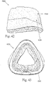
- the cross section at the nasal bridge region NB is generally triangular.
- the cross section at the nasal bridge region NB may also be another other reasonable shape, such as generally rectangular, oval, octagonal etc.
- the cross section at the nasal bridge region may also be an irregular shape.
- Fig, 20 shows an alternative cross section for the nasal bridge region.
- radius r1 at the apex 2010 of the cross section may be relatively small or sharp radius at the nasal bridge region NB.
- radius r1 may be between 1 to 4 nun.
- This relatively small or sharp radius at radius r1 provides the advantage that the cushioning component is kept away from the patient's eyes, especially when the cushioning component is compressed and inflated with air pressure in use.
- the relatively small or sharp radius at radius r1 may also enable minimal contact of the mask with the patient's skin, so as to make the mask feel more comfortable and less obtrusive.
- apex 2010 of the generally triangular cross section may be skewed or offset.
- the apexes or the corners of the generally triangular cross sectional may be rounded to promote a better fit with the patient and/or a better seal.
- This offset is shown on Fig. 20 , where apex 2010 and center line 2015 are spaced by distance 2020.
- Distance 2020 may be preferably around 1-2mm at the position proximal to the patient's nose.
- the comparable offset in the cushioning component about the portion adapted to cover the bottom lip of the patient is preferably 8mm.
- the comparable offset in the cushioning component about the portion adapted to cover the cheeks of the patient is preferably 1,25mm.
- Fig. 20 demonstrates an offset towards the inner edge of the cushioning component. Alternatively the apex may be skewed, or over the outer edge of the cushioning component.
- the generally triangular cross section of the cushioning portion may also additionally be defined has having three sides: an inner side which faces into the centre of the mask; an outer side facing away from the centre of the mask and a base surface, which may be adapted to be joined to a clip portion, at least in part.
- the outer side of surface of the cushioning portion is generally adapted to be longer than the inner surface. This may allow the cushioning component to, in effect, roll, bend or move inwards. The rolling motion leads to an extension of the sealing surface formed between the skin of the patient and the cushioning component. As the cushioning component is depressed, the contact region against the patient's skin is lengthened from the minimum contact point which is the apex to at least partially extending along the outer surface or side of the cushioning component.
- the apex of the triangle that contacts the user's face enables the cushion component 932 to deflect or roll such that if the apex is towards the inner part of the cushion component, the cushion component will roll inwards and over the clip portion 934 about hinge point 939,
- Air pressure AP from the CPAP device acts on the back of the rolled section of the cushion component 932 such that the air pressure forces the cushion component into sealing engagement on the patient's face.
- the rolling effect or the turning moment force, when the mask is pressed onto the face, can be also increased or assisted the positioning or shape of the clip portion attached to the cushioning portion.
- the clip portion 3234 may be joined to the base surface of the cross section of the cushioning component. More preferably, the clip is mounted proximal to the outer side of the cushioning component, and provides little or no support relative to the inner side of the cushioning component. Preferably, the clip portion may not generally support the inner side of the cushioning component.
- the clip portion includes a stepped configuration when viewed in accordance with its cross section.
- a preferred clip portion is joined to a cushioning portion.
- the stepped configuration is adapted to mate with a corresponding groove, slot or recess in the frame to provide aa seal.
- the step formation is oriented towards the outer side of the cushioning component for ease of use by the patient.
- the clip portion is joined to the cushioning component by an upper side.
- the upper side of the clip portion may be shaped to assist with: sealing of the cushioning component; comfort; and/or the aforementioned rolling effect of the cushioning component.
- the upper side of the clip portion has been angled towards the centre of the mask by lengthening the outer side of the clip portion relative to the shorter inner side of the clip portion. This angling of the upper surface of the clip portion is adapted to aid or assist in the rolling in effect of the cushioning component, Additionally, in the embodiments shown in Figs. 26-32 , the angled upper side of the clip portion has been included on the lower corners of the mask. For example, as shown in Figs.
- the upper surface of the clip portion is angled to enhance rolling and sealing in lower cheek and lip regions (e.g., al and a2 between about 0-20°).
- the angle of the upper surface in the chin region e.g., a3 between about 0-20°
- the angle of the upper surface in the chin region is oriented opposite that in the lower cheek and lip regions (e.g., the bottom lip region) ( Figs. 30 and 31 ), e.g., for manufacturability.
- the upper corner which is adapted to engage the nasal bridge of the patient the upper surface of the clip portion is flat and not angled towards to the centre of the mask. This is generally because the region around the nose doesn't requite as much "roll” as the sealing area against the sides of the nose is relatively long compared the regions around or about the cheeks of the patient. This feature is demonstrated in Figs. 27 and 28 ,
- the nasal bridge region also includes a modification to the base surface, wherein the base surface has been reduced or shortened to thereby reduce the volume of foam material rolled inwards at the nasal bridge.
- Fig. 32 depicts the interfacing structure wherein the upper surface of the clip surface has been angled outwards relative to the centre of the mask. This reduces the effect of "roll in” in the predetermined regions including this outwardly disposed angle of the upper surface.
- the outwardly disposed angle of the upper surface is suitable for regions requiring reduced “roll in” such as around the bottom lip or around the upper lip (in the nasal mask configurations).
- Another way to regulate "roll in” is by changing the amount of overhang of the cushioning component with respect to the clip portion.
- the inner apex 2050 of the cushion has the radius of curvature of between 3 to 1 0mm (most preferably 3-5mm). This is similarly shown in Fig, 19 , where the inner apex 2050 of the cushion has the radius of curvature.
- the size of this radius may affect the durability, and more specifically the tear strength of this region.
- inner edge 2090 may have an angle 2100 from the base of the cushioning component Angle 2100 may influence the amount of the cushioning component that may contact the patient.
- angle 2100 shown in Fig. 16f may be larger than angle 2100 shown in Fig. 20 , such that more of the cushioning component in Fig. 16f may contact the patient's face than that of Fig. 20 .
- angle 2100 may be about 90-95 degrees.
- the angle of the outer side or edge meeting the base surface is preferably between 78-83.
- the angle by which the outer side meets with the base surface is generally less than the angle formed between the inner side and the base surface.
- the most preferred maximum width of the nose bridge region (as measured along the base surface) is 22mm and most preferred maximum height of the cushioning component at the nose bridge position is approximately 24 mm.
- the cross section at the bottom lip region BL may preferably be generally trapezoidal,
- the cross section at the bottom lip region BL may also be another other reasonable shape, such as generally rectangular, oval, octagonal etc.
- the cross section at the bottom lip region may also be an irregular shape.
- Fig. 25 demonstrates this feature in a cross section for the bottom lip region.
- the apex 950 is skewed towards the centre of the mask, the outer side or surface of the cushioning component at the region that is adapted to contact the bottom lip region of the patient.
- the outer side has been divided into an upper and a lower portion, wherein the upper portion is at a reduced angle in respect to the lower portion.
- the apex 950 is adapted to rest or engage the cleft formed between the bottom lip of the patient and lower extremity of the chin.
- the upper portion is adapted to engage the patient's face at a position lower and extending away from the cleft. Thereby providing an increased sealing surface between: the patient's face at the location between the bottom lip and the lower extremity of the chin; and the outer side of the cushioning component.
- the patient contacting surface 940 is generally flat or has a larger radius r2 when compared to the nasal bridge region radius r1. This arrangement aids in comfort and increases the length of the sealing surface such that a better seal may be maintained.
- the radius r2 at the apex of the cushion is preferably about 5mm.
- patient contacting surface 940 may have apex 950 that may first contacts the patients face and anchors the cushion in the dimple of the chin or curvature between the lower lip and chin region.
- Apex 950 may have a relatively small radius r2 when compared to that radius r2 shown in Fig. 16g .
- Radius r2 may be about 5mm.
- Patient contacting surface 940 may also have a kink or inflexion 960 that may generally match the approximate curvature of the chin so as to rest the cushion on the chin to sealingly engage the cushion with the patient.
- This kink 960 also allows apex 950 to flex inwards towards the centre of the cushion, and outwards away from the centre of the cushion, so as to accommodate movement of the patient's chin or jaw. For example, it is possible for patients to drop their jaw during sleep, so in order to maintain a seal with the patient, the mask must be able to move with the patient's jaw. This arrangement further enables a greater fit range of patients, i.e. kink 960 may flex either inwards or outwards on a patient's jaw depending on the length and depth of their chin, other facial features etc,
- the internal wall 942 of the cushioning component is arranged substantially vertical or normal to the face of the patient in use as demonstrated by angle 2150. This arrangement reduces the likelihood of the foam cushioning component touching the patient's bottom lip when compressed in use, a problem that may occur for larger faces within each size range.
- the preferred maximum width of the cushioning component as measured in respect of the base surface is generally about 35mm in relation to the bottom lip region.
- the preferred maximum height of the cushioning component is generally about 26mm in relation to the bottom lip region.
- the angle formed between the outer side and base surface is approximately between 80-90 degrees; and the angle formed between the inner side and the base surface is approximately between 90 to 100 degrees.
- the angle by which the outer side meets with the base surface is generally less than the angle formed between the inner side and the base surface.
- the cross section at the side nose SN is generally triangular.
- the cross section at the side nose region SN may also be another other reasonable shape, such as generally rectangular, oval, octagonal etc.
- the cross section at the side nose region may also be an irregular shape.
- Figs. 21 and 22 show an alternative cross section for the side of nose region.
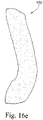
- Fig. 16h shows a cross-section of the cushioning component in a side of nose region SN. Similar to the nasal bridge region NB as shown in Fig. 16g , the cross section is generally triangular, However the triangular cross section is skewed or biased towards the inner edge of the cushioning component. This arrangement aids with sealing because inner wall 944 abuts the side of the patient's nose in use, thereby increasing the sealing surface. This is similarly demonstrated in Figs. 21 and 22 .
- the outer side is longer than the inner side.
- the angle formed between the outer side and the base surface is generally less than the angle formed between the inner side and the base surface.
- the most preferred maximum width of the side of nose region (as measured along the base surface) is 22mm. and most preferred maximum height of the cushioning component at the side of nose position is approximately 24mm,
- the cross section at the cheeks C is generally trapezoidal or triangular.
- the cross section at the cheeks region C may also be another other reasonable shape, such as generally rectangular, oval, octagonal etc.
- the cross section at the cheeks region may also be an irregular shape.
- Figs. 23 and 24 show an alternative cross section for the cheek region.
- Fig. 16i shows a cross-section of the cushioning component in a cheek region C.
- the contacting surface or apex 946 where the cushioning component contacts the patient's cheek is similar to that at the bottom lip region BL as shown in Fig. 16g .
- the cross section is generally triangular, and may have a smaller top surface 946 when compared to the top surface 940 of the bottom lip region BL. This arrangement aids sealing around the patient's cheeks in use and increases the comfort of the interfacing portion, while reducing the bulk of the interfacing portion at the cheek region C.
- inflexion 950 changes the curvature of the side wall of the cushion so that it may hinge or bend inwards. This may increase the ability for the cushion to seal on the patient's face when in use.
- the outer side of cushioning component is longer than the inner side, Also preferably, the angle formed between the outer side and the base surface is generally less than the angle formed between the inner side and the base surface.
- the most preferred maximum width of the cheek region (as measured along the base surface) is 23mm and most preferred maximum height of the cushioning component at the cheek region is approximately 24mm.
- the apex of the cushion is additionally offset towards the centre or middle of the mask.
- the apex may be offset to the extent that it overhangs the point formed between the inner side and the base surface.
- Cushion component 4000 may be used as a nasal mask that only covers the nose of the patient in use, and is positioned on the nose bridge, side of nose, cheeks and or upper lip region and may not cover the patient's mouth.
- the cushioning component of the nasal mask shown in respect of these embodiments is preferably: 70-75mm in length (when measured from the outer most edges of the base surface of the cushioning component); and the width of the cushioning component is approximately 75-80mm.
- the nasal bridge region 4200, side of nose region 4300 and cheek region 4400 may be generally similar to that described above for a full face cushion.
- the preferred height of the cushioning component at the region designated to correspond to the nasal bridge of the patient is approximately 22mm.
- the height of the cushioning component at the position designated to meet the side of the nose is approximately 25-27mm.
- the height of the cushioning component at the position designated to meet the patient's cheek regions is approximately 27mm.
- the preferred width of the cushioning component in the side of nose regions is typically about 20mm, Whereas the preferred width of the cushioning component in the cheek regions is typically about 18mm.
- cushion component 4000 may have an upper lip region 4100 that has a dip or region of reduced height (when viewed from a side view as shown in Fig. 41 ) relative to the height of other regions 4200. This feature may accommodate various upper lip regions of patients whilst avoiding accidental occlusion of the nares. The overall reduction in the amount of foam material may reduce the risks for patients.
- the preferred width of the cushioning component in the upper lip region is typically about 16mm.
- the width of the cushioning component in the upper lip region may be 10-20mm.
- the width of the cushioning component in the upper lip region may be 15-20mm.
- the width of the cushioning component in the upper lip region may be 12-20mm.
- the width of the cushioning component in the upper lip region may be 10-15mm.
- the width of the cushioning component in the upper lip region may be 10-18mm.
- the width of the cushioning component in the upper lip region may be 10-14nun.
- the preferred height of the cushioning component at the region designated to correspond to the upper lip of the patient is approximately 18mm.
- the height of the cushioning component in the upper lip region may be 10-20mm.
- the height of the cushioning component in the upper lip region may be 10-25mm.
- the height of the cushioning component in the upper lip region may be 15-20mm.
- the height of the cushioning component in the upper lip region may be 16-23mm.
- a mask assembly in accordance with the invention provides an improved fit range. This maybe preferably achieved by combining a more comfortable and compliant material with a more anatomically neutral geometry that seals against a wider range of facial anatomy for a given shape.
- the versatility of a chosen cushion shape, and hence its fit range performance, is also enhanced by the 'hovercraft' behavior exhibited by the cushion.
- the "hovercraft' behavior is generally defined by the air pressure in the cavity of the mask when the air pressure in cavity of the mask is greater than the outside environmental air pressure and thereby allows the mask to float on the face of the wearer.
- the pressure seal is preferably formed by the cushioning component. This feature may enhance the ease and speed of fitting the mask.
- the cushion material When pressurized with air the cushion material has extra extensibility compared to other known cushion materials.
- the soft flexible cells in the foam material effectively stretch when inflated allowing the material the freedom to enlarge. This allows the cushion material to have an extra dimension of conformability over other cushion materials known in the art e.g. silicone, by being able to expand and morph to facial anatomy when inflated with air pressure.
- the cushioning component is preferably made from unskinned foam, one or more cutting processes may be used to create the part, such cutting processes including die cutting, and/or machining, etc.
- the cushioning component may be molded with measures taken in the process to minimize the skin on the foam component, or the skin being subsequently removed from the molded component in a post process e.g. machined.
- the foam material used in the herein described embodiments may be an open and closed cell foam.
- the foam material used may be an open cell foam.
- the foam material used may be a closed cell foam,
- both an inside surface and an outside surface of the foam cushion component 232 are die cut. This typically results in generally straight cut edges.
- the cushion in these embodiments may have a generally rectangular cross section, where the top surface is generally substantially parallel to the patient's face in use, and the inner and outer side surfaces are generally perpendicular to the patient's face in use. It may be possible to die cut the foam using additional processing steps to create a non-rectangular cross section, e.g. the use of shims.
- the die cutting of a cushion component then from a flat sheet of foam results in a flat backed cushion component which may subsequently take the shape of a clip that it is assembled to e.g. glued.
- the foam cushion is therefore deformed into its final intended shape.
- the cushion component may be die cut from a foam sheet that is cut into a curved shape rather than a flat sheet.
- the curved sheets may be formed from a known process referred to as contour cutting, where a foam block is cut into curved sheets by being fed into an oscillating blade that changes position and orientation during the cutting process.
- the cushioning component e.g., as shown in Figs. 9a to 12f , may be cut into a three-dimensional shape or geometry using the techniques described in AU 2008904769 and AU 2008904778 ,
- Figs. 9a to 9d illustrate a foam-based interfacing structure 430 including a foam cushion component 432 and a clip portion 434.
- Outer wall 400 may include contours and curvature incorporated into the design.
- the inner, patient contacting wall (or orifice) 402 may be die cut as known in the art. Again, this typically results in straight cut edges (e.g., see Figs. 9b and 9d ).
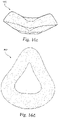
- Figs. 10a to 10c illustrate a foam-based interfacing structure 330 including a foam cushion component 332 and a clip portion 334, wherein the cushion component 332 includes localized regions with curvature or ridges, e.g., ridges 350 along cheek regions of the cushion component, a curvature 352 along the nasal bridge region of the cushion component, etc.
- the cushion component 332 is contoured along the chin region of the cushion component. The straight die cut inner and outer edges remain perpendicular to the patient's face in use similar to the previous embodiment.
- Figs. 1 lato 11c illustrate a foam-based interfacing structure 530 where a localized region 552 in the cushion component 532 at the nasal bridge has been raised, e.g., formed with a curved surface.
- Figs. 12a to 12f illustrate another embodiment in which a foam-based interfacing structure 630 including a foam cushion component 632 and a clip portion 634, wherein the foam cushion component 632 includes a slab of foam that is cut using methods known in the art. This process may be repeated in order to cut the outer wall 600 of the cushion component and then the inner, patient contacting wall (or orifice) 602 of the cushion component.
- the cushion-to-frame component may be made from a material that has greater structural integrity than the cushioning component.
- the clip is made from polyurethane foam that has higher hardness, higher density, and lower permeability than the foam used for the cushioning component.
- the clip/cushion-to-Trame component may be formed in a mould giving rise to a harder, denser, lower permeability . foam having a skin.
- the clip may be constructed of a non-foamed polymer, for example (but not limited to), nylon, polycarbonate, polypropylene.
- the clip portion or clip component may be of reduced hardness or increased flexibility in comparison to the frame portion of the mask to which it is to connected or secured with,
- the clip 934 is shown generally in Fig. 13 , and in more detail in Figs. 15a-15e .
- the clip 934 is generally shaped in order to align with the frame.
- the general curvature of the clip 934 can be altered to suit the frame to which it is to be fitted.
- the general curvature of the clip may also be used to shape the cushion component. Since the cushion component is made from compliant foam, it will readily adapt to the shape of the clip when joined together. An example of where this may be an advantage is when the cushion component is made to have a flat back (from a flat foam sheet as described previously) and is given its final shape by assembly (e.g. glued) to a clip that gives the cushion its intended shape (e.g. curved).
- the clip may also be made flat.
- the cushion can therefore also be made with a flat back to match the clip.
- the overall intended shape of the interfacing structure (combination of clip and cushion) can therefore be alternatively achieved by the flat clip and cushion being deformed and retained into a curved frame.
- This embodiment allows clip to be manufactured flat which can have several advantages including ease of handling and alignment during manufacture, packaging and transportation.
- the clip can therefore be formed by alternative methods e.g. die cutting from flat sheet material.
- the clip may also be made curved. This may be achieved by several means including molding directly into a curved shape, die cutting from curved (contour cut) sheet, or heat forming a flat clip die cut from a thermoformable material. Having the clip curved allows ease of alignment and assembly to a curved frame, as well as giving the cushion a curved shape if the cushion is made from a process that results in it having a flat back,
- the clip is made from molded polyurethane.
- the cushion contacting surface 935 is generally smooth so that it can continuously join and seal to the underside of the cushion.
- Cushion contacting surface 935 has a lip 935a to enable alignment of the clip to the frame.
- Frame contacting surface 937 has three alignment tabs 938 protruding from its surface that engage with the frame. There may be any number of alignment tabs 938 to aid the patient in aligning the interface structure with the anchoring structure. It should also be appreciated that the clip need not have alignment tabs 938 to engage the clip with the frame.
- the clip may also be made to incorporate features that engage the frame to aid retention of the interfacing structure to the frame. Examples include, but are not limited to, surface roughening, ribs, notches, snaps etc.
- the clip component may be separately formed as will be now described, or insert molded as will be described later in this specification.
- Figs. 18a to 18c illustrate a tool to mold a clip portion by itself, where the clip portion may subsequently be attached to the cushion component, e.g., by an adhesive or simply adhesion between the clip and cushion component.
- the tool includes a top half 1560 and a bottom half 1565 which are adapted to be joined together to form the clip portion.
- the tool provides a curved parting line PL between the top and bottom halves 1560, 1565.
- the bottom half 1565 includes a cavity 1567 adapted to receive the material (e.g., foaming mixture) that will form the clip portion. Also, the center section 1568 of the bottom half 1565 accommodates a separate insert that acts as a manual ejection feature after molding, The top half 1560 provides a surface 1562 that will form the side of the clip portion for interfacing or joining with the cushion component.
- the material e.g., foaming mixture
- the top and bottom halves 1560, 1565 of the tool are constructed and/or arranged to facilitate demolding of the clip portion from the tool so that the clip portion will not adhere to the tool.
- the top and bottom halves 1560, 1565 may be constructed of a material from which the mold material (e.g., foaming mixture) may be removed (e.g., high density polypropylene, silicone).
- a demolding agent e.g., wax
- wax may be provided to the top and bottom halves to facilitate demolding.
- An alternative demolding aid may be a release film that lines the tool and releases from the clip material easily after molding.
- the release film may double, in whole or in part, as the packaging for the interfacing structure such that the product leaves the molding process already packaged.
- the clip includes a tab at one or a number of locations that facilitates gripping of the part for demolding during the manufacturing process. This tab feature may also double as an alignment feature for assembly and a gripping feature for disassembly for the user of the mask assembly.
- the clip may include a tab feature that includes an end of life indicator for the interfacing structure.
- the width of the clip portion may preferably match or be less than the maximum width of the cushion component
- the width of the cross section of clip portion may be less than the width of the cross section of the cushion component.
- the clip portion provides different forms of support to the cushion component.
- the clip portion and cushion component may be arranged such that (i) the outer perimeter of the clip portion and cushion component align (hides hardness of clip portion and provides desired freedom of movement in the cushion component), (ii) the inner perimeter of the clip portion and the cushion component align, or (iii) neither the inner or outer perimeter of the clip portion and the cushion component align.
- the clip portion and cushion component may be arranged such that (i) the outer perimeter of the clip portion and cushion component align, (ii) the inner perimeter of the clip portion and cushion component align, or (iii) neither the inner or outer perimeter of the clip portion and the cushion component align.
- the cushion component may preferably be more able to flex in regions or directions not having a clip portion next to it than in regions having a clip portion adjacent to it or supporting it. For example, where the cushion component overhangs the clip portion, that overhanging region of the cushion component has more freedom to move. This arrangement can be more comfortable and more able to adapt to different geometries of a person, and provide the correct vectors to seal the cushion component against the face.
- the clip portion is to be joined to a cushioning component by a base surface of the cushioning component. It may also be preferably to arrange the clip portion to support the external extremity (relative to the circumference of the mask) of the base surface and to have no or little support inner extremity of the base surface.
- the inner portion of the cushion component When used as part of a respiratory mask, it may be preferable that the inner portion of the cushion component overhang the clip portion.
- the face of the patient may engage with an unsupported inner edge of the softer cushion component causing it to bend and conform to the individual patient's shape.
- the cushioning component When the mask engages a patient's face, the cushioning component may roll inwards towards the centre of the mask when pressure is applied on the mask towards the patient's face.
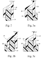
- Fig. 7a shows an elevation view detail from the frame side of the interfacing structure 230 shown in Fig. 4e in a nasal bridge region.
- Fig. 7b shows that the width w2 of the clip portion 234 is less than the width w1 of the cushion component 232 and that the outer perimeter of the clip portion 234 and the cushion component 232 are aligned.
- An advantage of this arrangement is illustrated in Fig. 7c where in use the nose is able to push the inner perimeter of the cushion component 232 in the direction shown by the arrow, in a cantilever manner as well as compressing.
- Fig. 8 is a cross-section showing the clip portion 234 of the interfacing structure 230 received within the channel 22 of a mask frame 20.
- Figs. 26-32 show an alternative embodiment of the present invention.
- Fig, 26 shows the cross sections later shown in Figs. 27-32 .
- Cushion component 3232 may be attached to clip component 3234.
- Cushion component 3232 may be similar to that shown in Figs. 19-25 .
- Clip component 3234 may have upper surface 3500 that attaches to cushion component 3232.
- Upper surface 3500 may be generally horizontal when in use or assembled, as shown in Fig. 27, 28 , and 29 . In addition, this may position the tangent to apex 3600 of the cushion component 3232 generally parallel to upper surface 3500.
- upper surface 3500 may be generally curved or angled inwards towards the inner portion of the cushion so as to angle the cushion more towards the centre of the patient's face, as shown in Figs. 30 , 31, and 32 . Therefore, tangent to apex 3600 may not be parallel to upper surface 3500.
- the upper surface 3500 may be angled in one or more selected regions, e.g., lower cheek or chin regions to fit patients with more narrow, shallow faces (see Figs, 30-32 ).
- the outer edge of the cushion component may slightly overhang (e.g., 1 mm overhang) the clip component, e.g., for manufacturability,
- the two layers may be adhered to one another using polyurethane hot melt glue or cyanoacrylate.
- the cushioning portion may be directly glued onto the frame.
- insert molding may be used to assemble the cushioning component to the cushion-to-frame component.
- An advantage of this approach include lower cost when compared to other processes such as gluing.
- Figs, 17a to 17h illustrate a tool and manufacturing process for manufacturing an interfacing structure according to an embodiment of the present invention.
- the tool includes a first portion 1060 adapted to receive the cushioning component that may be cut from foam slabstock and a second portion 1065 adapted to receive the foaming mixture that will form the cushion-to-frame component,
- the first portion 1060 of the tool may allow a vacuum to be applied to the cushioning component to retain it in position.
- the walls of the cavity that receive the cushioning component include a plurality of orifices 1062, and a vacuum is applied to an opening 1063 in the side wall of the first portion 1060 so that the cushioning component may be drawn into the cavity.
- the first portion 1060 may be sized to provide an interference fit with the cushioning component.
- the first and second portions 1060, 1065 of the tool are arranged so that there will be a region of contact between the cushioning component and the cushion-to-frame component such that they will adhere to one another,
- At least a second portion of the tool is constructed and/or arranged to facilitate demolding of the cushion-to-frame component that would otherwise adhere to the tool.
- this is achieved by using a tool constructed of a material from which the foam may be removed (e.g., high density polypropylene, silicone).
- a tool constructed of a material from which the foam may be removed e.g., high density polypropylene, silicone.
- steel or aluminum tools may be used, provided an appropriate de-molding agent can be used, such as wax (e.g., agent that does not present biocompatibility issues).
- the second portion 1065 includes three parts that are removably attached to one another, i.e., an inner portion 1066(1), and outer portion 1066(2), and a ring portion 1066(3).
- Fig. 17a illustrates the first and second portions 1060, 1065 of the tool separated from one another
- the cushioning component 1032 is placed in the first portion 1060 of the tool.
- the cushioning component 1032 may be held in place in the first portion 1060 by a vacuum and may impart curvature on the cushioning component via the vacuum. This may be necessary if the cushion is made from a process that gives is a flat backed geometry. Placement of the cushioning component 1032 may be manual or automated. For example, the cushioning component 1032 may be sucked into the first portion 1060 using the vacuum.
- a mixture of polyurethane e.g. foam or elastomer
- the high-intensity mix is poured into the second portion 1065 of the tool. Pouring of the mix for the cushion-to-frame component 1034 may be manual or automated. If the cushion-to-frame component 1034 is made from a foam the cavity of the second portion 1065 will only be partly filled (e.g., 25%) and during the foaming process it will expand to fill the space and come into contact with the cushioning component where it will adhere.
- the first and second portions 1060, 1065 of the tool are clamped together or closed to allow the cushion-to-frame component foaming reaction to proceed in the tool. That is, the foam for the cushion-to-frame component 1034 can rise up and chemically bond or adhere to the foam cushioning component 1032.
- the choice of clip material may enhance the bonding or adhesion process.
- both the clip and the cushion are made from polyurethane material for ideal bond integrity between the two components.
- the clip component may infuse into gaps in the cell structure of the cushion component, forming small mechanical bonds between the components.
- Fig. 17f When the cushion-to-frame component 1034 has cured, the vacuum first portion and second portion are separated as shown in Fig. 17f , In Fig. 17g , the ring portion 1066(3) at the bottom of the second portion 1065 is removed and the inner portion 1066(1) is ejected to demold the cushion-to-frame component 1034.
- Fig. 17h shows the resulting interfacing structure 1030 removed from the tool with the cushioning component 1032 adhered to the cushion-to-frame component 1034.
- the cushion component is originally flat when vacuum inserted into the top half of the tool and is bonded to a curved clip during the insert molding process. The resultant interfacing structure then assumes an intended curved shape.
- the cushion and clip are made flat but the cushion is made with sufficient depth to not require curvature to suitably adapt to the face when worn; but rather suitably deforms to the shape of the face due to the softness and depth of the cushion foam.
- a film may be added to the second portion of the tool prior to the addition of the foaming mixture.
- This film may be structured to facilitate removal of the otherwise adhering cushion-to-frame component.
- the film may be used to form packaging for the interfacing structure.
- the clip portion of the interfacing structure may be constructed from more rigid and denser foam than the cushion component.
- the clip portion may be formed from nitrogen blown polyethylene, or some other biocompatible foam having a fine cell-structure.
- the clip portion could be made from some other polymer or rubber.
- the clip portion is adapted to form a cushion-to-frame engagement mechanism and to form a structural support for the cushion component.
- the cushioning component is less rigid, less stiff or more flexible than the clip portion, which is in turn less rigid, less stiff or more flexible than the frame of the mask.
- the frame gives shape to the mask interfacing structure, wherein the interfacing structure is relatively flexible and less rigid, overall than the frame. This feature adds comfort and also allows the interfacing structure to be easily replaced by the patient or user. Further improvements to the interfacing structure may be made to adapt the shape and configuration to be disposable.
- Fig. 13 shows a clip portion 734 including a side 735 for interfacing with a foam-based cushion component and a side 737 for interfacing with a mask frame.
- the clip portion 734 is constructed of a skinned foam and may be formed by molding.
- the foam of the clip portion 734 may be harder or more dense than the foam of the cushion component.
- the more dense or harder foam may be formed by cutting, e.g., die cutting, machining, and/or the methods set forth in AU 2008904769 and AU 2008904778 .
- This arrangement provides a one piece interfacing structure with a cushion component adapted to engage the patient's face and a clip portion adapted to interface with the mask frame.
- a mask system may be provided that includes at least two different forms of interfacing structure chosen from the set of foam-based cushion, silicone-based cushion, and gel-based cushion.
- Figs. 14a to 16i illustrate an interfacing structure 930 including a cushion component 932 and a cushion-to-frame component or clip portion 934 provided to the cushioning component 932.
- Figs, 14a to 14f show the cushioning component 932 attached to the cushion-to-frame, component 934, Figs. 15a to 15e are isolated views of the cushion-to-frame component 934, and Figs. 16a to 16i are isolated views of the cushioning component 932.
- the cushion-to-frame component 934 includes a side 935 for interfacing with the cushioning component 932 and a side 937 for interfacing with a mask frame.
- the side 937 includes protrusions 938 to facilitate and/or enhance attachment to the mask frame.
- the interfacing structure is constructed as described above and arranged for removable interconnection with the rest of the apparatus, for example a respiratory mask.
- interfacing structure enables one to replace the interfacing structure should it become soiled, damaged, uncomfortable or otherwise aged as a result of usage. It also facilitates trial or testing of different arrays of interfacing structures which are selected on different patients facial types or features (e.g., narrower face, longer nose, or longer chin, etc.).
- One form of interfacing structure for example a foam-based interfacing structure, may be used as a form of "training" system to allow a person to become accustomed to the sensation of wearing and using a mask.
- a foam-cushion based mask may provide an initially more appealing and comfortable surface for a new patient than a gel or silicone-based cushion. The patient may subsequently switch from the foam-based cushion to a silicone or gel based cushion. In this way, the patient may be more likely to adhere to therapy because they are used to the very soft comfortable feeling of foam.
- the interfacing structure When applied to respiratory equipment, the interfacing structure is adapted for connection with a mask frame. In use, a seal is formed between the interfacing structure and the frame. This arrangement could be used for both nasal and full-face masks. The seal between the frame and interfacing structure may seal better wherein the clip portion is less rigid or more flexible than the frame.
- Fig. 1 illustrates a mask 10 including a mask frame 20 a foam-based interfacing structure 30 provided to the mask frame 20.
- the foam-based interfacing structure 30 provides a foam cushion component 32 adapted to contact the patient's face in use.
- the foam-based interfacing structure 30 is adapted for use with an existing mask (e.g., ResMed's Mirage Quattro mask), which allows the patient to switch from the foam-based interfacing structure 30 to the mask's existing silicone-based cushion if desired.
- an existing mask e.g., ResMed's Mirage Quattro mask
- Figs. 4a to 4g show a foam-based interfacing structure 230 according to an embodiment of the invention.
- the interfacing structure 230 includes a cushion component or face-contacting portion 232 and a clip portion 234 provided to the cushion component 232,
- the clip portion 234 is adapted for an interference fit with a mask frame, and the width of the clip portion 234 is narrower than the width of the cushion component 232 (e.g., see Figs. 4e and 4g ).
- the cushion-to-frame engagement and connection mechanism provided by the clip portion may include a channel-type engagement or rib-type engagement.
- the channel-type engagement includes a foam clip portion 34 that is adapted to be received within the channel 22 of a mask frame 20 with an interference fit.
- the foam clip portion 34 extends around the entire perimeter of the interfacing structure so as to form a seal and retention with the mask frame.
- the rib-type engagement includes a foam clip portion 34 with one or more slots 38 to receive inner and/or outer ribs 23, 24 of the mask frame 20.
- the slot to rib engagement may provide an inner frame rib engagement (see Fig. 3a ), an outer frame rib engagement (see Fig. 3b ), or an inner and outer frame rib engagement (see Fig. 3c ). This arrangement provides a broader base of support for the sealing foam.
- Figs. 5a and 5b illustrate a foam-based interfacing structure 830 including a foam cushion component 832 and a clip portion 834
- Fig. 5c illustrates the interfacing structure 830 provided to a mask frame 20
- the clip portion 834 includes a slot 838 adapted to receive a rib of the mask frame 20. Also, providing a wider clip portion 834 allows more stiffness and structural integrity to be provided to the clip portion, making the clip portion easier to assemble to the mask frame.
- the clip portion When structured to form an interference fit with, the mask frame, the clip portion may have the following properties: appropriate rigidity (e.g., less than that of the frame and in one form more rigid than the foam cushion component); non-porous; and/or low compression set (the amount of deformation expressed as a percentage of original dimensions) which a material retains after compressive stress is released (in this way, the clip portion maintains its retention force during its usage life).
- appropriate rigidity e.g., less than that of the frame and in one form more rigid than the foam cushion component
- non-porous e.g., the amount of deformation expressed as a percentage of original dimensions
- the clip portion may include an additional extension (not shown) that extends beyond the outer extremity of the frame which is adapted to be gripped by the patient for easier removal of the interfacing structure.
- this extension would be positioned in a region that is easy for the patient to grip such as the nasal bridge of the mask, Preferably, the extension will be small enough not to impede vision of the user or to affect the overall efficiency or seal of the mask.
- the extension may function as a finger grip for the patient to remove or replace the interfacing structure, when desired.
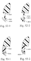
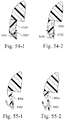
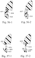
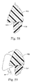
- Figs. 50-1 to 57-2 illustrate alternative mechanisms for attaching the clip portion to the frame.
- the clip portion 5034 is in the form of a microcellular polyurethane clip adapted to engage within the frame channel 5022 with an interference fit.
- the clip portion 5034 is in the form of a flexible plastic clip (e.g., Hytrel, TPE) adapted to engage the frame channel 5022 with a snap fit.
- the clip portion also includes a lip seal 5035 adapted to engage the channel wall.
- the clip portion 5034 is in the form of a flexible plastic clip adapted to engage the frame channel 5022 with a snap fit.
- the clip portion also includes a sealing element 5035 (thermoplastic elastomer that may be over molded on to the clip portion) adapted to engage the channel wall.
- a sealing element 5035 thermoplastic elastomer that may be over molded on to the clip portion
- the clip portion 5034 is in the form of a polyurethane clip adapted to engage within the frame channel 5022 with an interference fit.
- the clip portion also includes a flexible plastic clip 5036 (assembled to the polyurethane clip) adapted to engage the frame channel with a snap fit.
- the clip portion 5034 is in the form of a polyurethane clip adapted to engage within the frame channel 5022 with an interference fit.
- the clip portion also includes a flexible plastic clip 5036 (glued to the polyurethane clip) adapted to engage the frame channel with a snap fit.
- the clip portion 5034 includes a flexible plastic clip adapted to engage the frame channel 5022 with a snap fit or other fitting means e.g. interference fit.
- the clip is contoured such that the clip also engages the channel wall with an interference fit.
- the clip portion 5034 includes a flexible plastic clip adapted to engage the frame channel with a snap fit.
- the clip portion also includes a foam element 5037 adapted to cover the clip.
- the clip portion 5034 includes a polyurethane clip (attached to cushion component by plastic element 5038) adapted to engage the frame channel 5022 with a snap fit.
- the frame channel includes a plastic extension 5023 adapted to engage the clip. This arrangement allows replacement of the cushion component without the need to change the clip portion.
- the cushion component may be made from polyurethane, be resistance to hydrolysis and/or resistant to microbial attack.
- the cushion component may be air permeable. In an embodiment, the cushion component may not be air permeable.
- the cushion component may be able to maintain its air permeability over a period of use.
- the cushion component may not emit harmful or odorous volatiles or particulates.
- the cushion component may be coloured and this colour may not fade.
- Fig. 48 is a chart showing exemplary material properties for the cushion component.
- properties of the foam cushion component may include; density (relates to other foam properties and affects cost and weight of the cushion, e.g., higher density can reduce air permeability and higher density can increase hardness); air permeability (flow of air through cushion contributes to total mask flow characteristic of the mask which may affect compatibility with PAP devices); hardness (affects comfort and sealing performance); tear resistance (contributes to durability); tensile strength (contributes to durability); and/or tensile stiffness (resists the deforming effects of positive air pressure inside the mask).
- Fig. 49 is a chart showing exemplary material properties for the clip portion.
- properties of the foam clip portion may include: density (affects weight); air permeability (permeability of the foam itself may not be critical if it is molded with a skin that renders it impermeable); hardness (soft and flexible enough to assemble to the frame with an interference fit and seal against the frame); elasticity/viscoelasticity (soft and flexible enough to assemble to the frame with an interference fit and seal against the frame); and/or compression set (should not deform over time to ensure easy assembly/retention).
- the following provides exemplary testing methods for determining material properties.
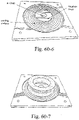
- Air permeability is defined as "the rate of air flowing through a foam sample (in L/min)".
- test measures the flow through a regular shape with a constant cross section, in a manner analogous to a cushion in real use.
- the test specimen is an annulus of foam, about 30 mm thick. The circular shape ensures that pressure is evenly distributed and the foam inflates uniformly.
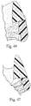
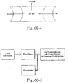
- the foam sample is cut normal to cell rise direction as shown in Fig. 60-4 . .
- the wall section of the foam specimen may be rectangular (see Fig. 60-2 ), but it is possible for the wall section to have a concave outer surface and a convex inner surface (see Fig. 60-3 ).
- Fig. 60-5 is a schematic of the test set up.
- the test jig used to hold the foam consists of: an aluminum base plate that locates the foam and seals against the flat bottom surface of foam annulus; an air inlet and pressure port in the centre of the base plate; a clear polycarbonate top plate that seals against the flat bottom surface of foam annulus and allows observation of the test sample; and a part glued to the top plate to connect with a load cell attachment on the Universal Testing Machine (UTM).
- UPM Universal Testing Machine
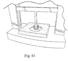
- Hardness is defines as "force required to indent a test piece of foam to a stated percentage of its original thickness”.
- Hardness may be tested using an IDM Universal Test Machine, or equivalent (e.g., see circular flat indenter of Fig, 61 )
- the sag factor or support factor i.e., the ratio of 65% to 25% IFD value.
- Tensile strength may be measured using an IDM Universal Test Machine, or equivalent. See Fig. 62-1 .
- Test both directions, i.e., parallel to and normal to the direction of cell rise.
- test pieces may be acceptable if the results are consistent (no individual value deviates more than 20% from the mean of the three values),
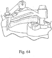
- Tear resistance is defined as the force required to propagate a tear in a pre-cut sample. See Fig. 63-1 .
- the speed of separation of the jaws holding the test piece shall be 200 mm/min.
- the cushion is compressed by 40% of its 30 mm thickness, i.e., 12 mm.
- a mask frame may be integrally molded or formed with the cushion-to-frame component 1034.
- the second portion 1065 of the tool may be structured to mold the cushion-to-frame component together with the mask frame.
- a polyurethane foam cushioning component is provided to a polyurethane foam or polyurethane elastomer cushion-to-frame component.
- one or both of the components may be constructed of a gel material,
- both components may be constructed of gel
- the cushioning component may be constructed of gel and the cushion-to-frame component may be constructed of foam
- the cushioning component may be constructed of foam and the cushion-to-frame component may be constructed of gel.
Landscapes
- Health & Medical Sciences (AREA)
- Emergency Medicine (AREA)
- Pulmonology (AREA)
- Engineering & Computer Science (AREA)
- Anesthesiology (AREA)
- Biomedical Technology (AREA)
- Heart & Thoracic Surgery (AREA)
- Hematology (AREA)
- Life Sciences & Earth Sciences (AREA)
- Animal Behavior & Ethology (AREA)
- General Health & Medical Sciences (AREA)
- Public Health (AREA)
- Veterinary Medicine (AREA)
- Respiratory Apparatuses And Protective Means (AREA)
- Orthopedics, Nursing, And Contraception (AREA)
- Accommodation For Nursing Or Treatment Tables (AREA)
- Devices For Medical Bathing And Washing (AREA)
Applications Claiming Priority (4)
| Application Number | Priority Date | Filing Date | Title |
|---|---|---|---|
| AU2008904769A AU2008904769A0 (en) | 2008-09-12 | A Foam-Based Interfacing Structure Method and Apparatus | |
| AU2008904778A AU2008904778A0 (en) | 2008-09-15 | A Foam-Based Interfacing Structure Method and Apparatus | |
| EP09812518.0A EP2344225B1 (en) | 2008-09-12 | 2009-09-03 | A foam-based interfacing structure |
| PCT/AU2009/001144 WO2010028425A1 (en) | 2008-09-12 | 2009-09-03 | A foam-based interfacing structure method and apparatus |
Related Parent Applications (1)
| Application Number | Title | Priority Date | Filing Date |
|---|---|---|---|
| EP09812518.0A Division EP2344225B1 (en) | 2008-09-12 | 2009-09-03 | A foam-based interfacing structure |
Publications (1)
| Publication Number | Publication Date |
|---|---|
| EP4039307A1 true EP4039307A1 (en) | 2022-08-10 |
Family
ID=42004706
Family Applications (2)
| Application Number | Title | Priority Date | Filing Date |
|---|---|---|---|
| EP21217202.7A Pending EP4039307A1 (en) | 2008-09-12 | 2009-09-03 | A foam-based interfacing structure |
| EP09812518.0A Active EP2344225B1 (en) | 2008-09-12 | 2009-09-03 | A foam-based interfacing structure |
Family Applications After (1)
| Application Number | Title | Priority Date | Filing Date |
|---|---|---|---|
| EP09812518.0A Active EP2344225B1 (en) | 2008-09-12 | 2009-09-03 | A foam-based interfacing structure |
Country Status (8)
| Country | Link |
|---|---|
| US (3) | US8869798B2 (ja) |
| EP (2) | EP4039307A1 (ja) |
| JP (3) | JP5554334B2 (ja) |
| CN (2) | CN102149422B (ja) |
| AU (2) | AU2009291491C1 (ja) |
| CA (2) | CA2941584C (ja) |
| NZ (7) | NZ719072A (ja) |
| WO (1) | WO2010028425A1 (ja) |
Families Citing this family (74)
| Publication number | Priority date | Publication date | Assignee | Title |
|---|---|---|---|---|
| NZ573196A (en) | 2002-09-06 | 2010-07-30 | Resmed Ltd | Cushion for a respiratory mask assembly with two force applying features for respectively low and high mask pressure |
| US8490623B2 (en) | 2002-11-06 | 2013-07-23 | Resmed Limited | Mask and components thereof |
| NZ626585A (en) | 2003-12-31 | 2016-02-26 | Resmed Ltd | Compact oronasal patient interface |
| WO2005079726A1 (en) | 2004-02-23 | 2005-09-01 | Fisher & Paykel Healthcare Limited | Breathing assistance apparatus |
| US9072852B2 (en) | 2004-04-02 | 2015-07-07 | Fisher & Paykel Healthcare Limited | Breathing assistance apparatus |
| EP3936180B1 (en) | 2004-04-02 | 2023-11-29 | Fisher & Paykel Healthcare Limited | Breathing assistance apparatus |
| JP4787243B2 (ja) | 2004-06-03 | 2011-10-05 | レスメド・リミテッド | 患者用中間装着部材のためのクッション |
| DE202006021260U1 (de) | 2005-01-12 | 2014-05-05 | Resmed Limited | Polster für Patientenschnittstelle |
| US8397728B2 (en) | 2005-10-14 | 2013-03-19 | Resmed Limited | Cushion to frame assembly mechanism |
| WO2007048174A1 (en) | 2005-10-25 | 2007-05-03 | Resmed Ltd | Interchangeable mask assembly |
| DE202007019687U1 (de) | 2006-07-14 | 2015-07-14 | Fisher & Paykel Healthcare Ltd. | Atemhilfsgerät |
| EP2425868B1 (en) | 2006-07-28 | 2014-11-19 | ResMed Limited | Delivery of respiratory therapy |
| EP3053621B1 (en) | 2006-07-28 | 2019-10-16 | ResMed Pty Ltd | Patient interface for delivery of respiratory therapy |
| JP5911189B2 (ja) | 2006-12-15 | 2016-04-27 | レスメド・リミテッドResMed Limited | 呼吸療法の実施 |
| US8517023B2 (en) | 2007-01-30 | 2013-08-27 | Resmed Limited | Mask system with interchangeable headgear connectors |
| NZ578334A (en) | 2007-04-19 | 2011-01-28 | Resmed Ltd | Mask frame connected to face cushion via intervening clip |
| NZ582559A (en) | 2007-07-30 | 2011-04-29 | Resmed Ltd | Breathable gas patient interface interlocking nasal prongs and frame unit |
| US11331447B2 (en) | 2008-03-04 | 2022-05-17 | ResMed Pty Ltd | Mask system with snap-fit shroud |
| US20110000492A1 (en) | 2008-03-04 | 2011-01-06 | Resmed Ltd | Foam respiratory mask |
| US8550084B2 (en) | 2008-03-04 | 2013-10-08 | Resmed Limited | Mask system |
| JP5518748B2 (ja) | 2008-03-04 | 2014-06-11 | レスメド・リミテッド | 発泡体クッション要素を含むインターフェース |
| US10792451B2 (en) | 2008-05-12 | 2020-10-06 | Fisher & Paykel Healthcare Limited | Patient interface and aspects thereof |
| US10258757B2 (en) | 2008-05-12 | 2019-04-16 | Fisher & Paykel Healthcare Limited | Patient interface and aspects thereof |
| US8905031B2 (en) | 2008-06-04 | 2014-12-09 | Resmed Limited | Patient interface systems |
| CN105126222A (zh) | 2008-06-04 | 2015-12-09 | 瑞思迈有限公司 | 患者接口系统 |
| US11660413B2 (en) | 2008-07-18 | 2023-05-30 | Fisher & Paykel Healthcare Limited | Breathing assistance apparatus |
| NZ719072A (en) | 2008-09-12 | 2018-01-26 | Resmed Ltd | A foam-based interfacing structure method and apparatus |
| ES2652561T3 (es) | 2008-10-10 | 2018-02-05 | Fisher & Paykel Healthcare Limited | Almohadillas nasales para una interfaz de paciente |
| EP2213324B1 (en) | 2009-01-30 | 2016-07-27 | ResMed R&D Germany GmbH | Patient interface structure and method/tool for manufacturing same |
| USD665493S1 (en) * | 2009-08-12 | 2012-08-14 | Resmed Limited | Cushion for respiratory mask |
| EP3741418B1 (en) | 2009-11-18 | 2024-05-08 | Fisher & Paykel Healthcare Limited | Nasal interface |
| EP4070841A1 (en) | 2010-10-08 | 2022-10-12 | Fisher & Paykel Healthcare Limited | Breathing assistance apparatus |
| US10137269B2 (en) | 2011-02-14 | 2018-11-27 | Resmed Limited | Cushion-to-frame component for an interfacing structure |
| US10603456B2 (en) | 2011-04-15 | 2020-03-31 | Fisher & Paykel Healthcare Limited | Interface comprising a nasal sealing portion |
| LT3117861T (lt) | 2011-04-15 | 2021-09-10 | Fisher&Paykel Healthcare Limited | Sąsaja, apimanti galinčią pasisukti nosies tiltelio dalį |
| EP3566736B1 (en) | 2011-07-01 | 2020-12-09 | Fisher & Paykel Healthcare Limited | Nasal mask interface assembly |
| EP2747825A2 (en) * | 2011-12-27 | 2014-07-02 | Koninklijke Philips N.V. | Patient interface, cushion thereof, and manufacturing method |
| CN104066473B (zh) | 2012-01-16 | 2017-06-30 | 皇家飞利浦有限公司 | 具有用于为用户提供低摩擦和改善的舒适度的工程化表面的患者界面装置 |
| JP6491479B2 (ja) | 2012-01-16 | 2019-03-27 | コーニンクレッカ フィリップス エヌ ヴェKoninklijke Philips N.V. | 使用者の皮膚又は外部組織に接触する器具の摩擦低減及び快適さの向上をもたらす工学表面 |
| WO2013186654A1 (en) * | 2012-06-13 | 2013-12-19 | Koninklijke Philips N.V. | Sealing cushion having angled sealing flap |
| SG10201913774QA (en) | 2012-08-08 | 2020-03-30 | Fisher & Paykel Healthcare Ltd | Headgear for patient interface |
| EP2892596B1 (en) | 2012-09-04 | 2023-07-26 | Fisher&Paykel Healthcare Limited | Valsalva mask |
| EP2931348B1 (en) | 2012-12-14 | 2021-09-22 | Koninklijke Philips N.V. | Respiratory interface device customization utilizing a generic cushion template |
| US10987477B2 (en) | 2013-02-04 | 2021-04-27 | ResMed Pty Ltd | Respiratory apparatus |
| USD809131S1 (en) | 2014-08-04 | 2018-01-30 | Resmed Limited | Respiratory mask assembly |
| US10004867B2 (en) | 2013-02-04 | 2018-06-26 | Resmed Limited | Respiratory apparatus |
| US10413692B2 (en) | 2013-02-04 | 2019-09-17 | ResMed Pty Ltd | Cushion assembly |
| EP4360684A2 (en) | 2013-02-04 | 2024-05-01 | ResMed Pty Ltd | Respiratory apparatus |
| GB201314886D0 (en) * | 2013-08-20 | 2013-10-02 | 3M Innovative Properties Co | Personal respiratory protection device |
| CN105744980A (zh) * | 2013-11-01 | 2016-07-06 | 皇家飞利浦有限公司 | 用于患者接口的密封衬垫 |
| RU2695885C1 (ru) * | 2013-12-20 | 2019-07-29 | Конинклейке Филипс Н.В. | Индивидуально настраиваемый лицевой уплотнительный элемент для респираторного устройства и способ индивидуальной настройки |
| GB2521644B (en) | 2013-12-24 | 2020-03-11 | Intersurgical Ag | Improvements relating to respiratory masks |
| CN113230512A (zh) * | 2014-03-18 | 2021-08-10 | 费雪派克医疗保健有限公司 | 凝胶复苏面罩 |
| WO2015141738A1 (ja) * | 2014-03-19 | 2015-09-24 | 公立大学法人名古屋市立大学 | 医療用マスク、これに用いる伸展シート及びフレーム |
| WO2015193408A1 (en) * | 2014-06-17 | 2015-12-23 | Resmed Limited | A seal forming structure for a patient interface and a tool and method of manufacturing the seal forming structure |
| CA3211125A1 (en) | 2014-08-25 | 2016-03-03 | Fisher & Paykel Healthcare Limited | Respiratory mask and related portions, components or sub-assemblies |
| WO2016030381A1 (en) * | 2014-08-28 | 2016-03-03 | Koninklijke Philips N.V. | Cpap pressurized gas permeable mask cushion |
| CN204217969U (zh) * | 2014-09-18 | 2015-03-25 | 宋搏 | 口罩 |
| WO2016054692A2 (en) * | 2014-10-10 | 2016-04-14 | Resmed Limited | Foam cushion respiratory apparatus |
| NZ770257A (en) | 2014-11-26 | 2023-06-30 | ResMed Pty Ltd | Textile patient interface |
| KR102562104B1 (ko) * | 2015-10-08 | 2023-08-01 | 프리시전 폼 테크놀로지즈 피티와이 리미티드 | 절단장치 |
| US20170168303A1 (en) * | 2015-12-09 | 2017-06-15 | Facebook, Inc. | Head-Mounted Display Systems with Nose Piece |
| WO2017120643A1 (en) | 2016-01-14 | 2017-07-20 | Resmed Limited | Oro-nasal patient interface |
| CN105768280A (zh) * | 2016-04-29 | 2016-07-20 | 宋搏 | 密封部件以及口罩 |
| USD895105S1 (en) * | 2016-10-24 | 2020-09-01 | ResMed Pty Ltd | Combined cushion and frame module for patient interface |
| EP4234224A3 (en) * | 2016-12-30 | 2023-10-18 | Fisher & Paykel Healthcare Limited | Thermoformed mask |
| USD824020S1 (en) | 2017-02-23 | 2018-07-24 | Fisher & Paykel Healthcare Limited | Cushion assembly for breathing mask assembly |
| USD823454S1 (en) | 2017-02-23 | 2018-07-17 | Fisher & Paykel Healthcare Limited | Cushion assembly for breathing mask assembly |
| USD823455S1 (en) | 2017-02-23 | 2018-07-17 | Fisher & Paykel Healthcare Limited | Cushion assembly for breathing mask assembly |
| CN109172977A (zh) * | 2018-10-12 | 2019-01-11 | 深圳瑞之谷医疗科技有限公司 | 柔性衬垫、呼吸用罩壳结构及呼吸界面接口 |
| US10974007B2 (en) * | 2019-03-07 | 2021-04-13 | Sleepnet Corporation | Facemask seal |
| US11571537B2 (en) | 2019-03-28 | 2023-02-07 | Koninklijke Philips N.V. | Adhesive alignment system for patient interfaces |
| CN110448778B (zh) * | 2019-09-02 | 2022-04-01 | 博义医疗器材(上海)有限公司 | 采用用独特方法制成的气囊作为气垫的麻醉面罩及其制作方法 |
| US11135459B1 (en) * | 2021-04-21 | 2021-10-05 | Robert Caldwell | Dual filtration COVID-19 mask |
Citations (3)
| Publication number | Priority date | Publication date | Assignee | Title |
|---|---|---|---|---|
| WO2004041342A1 (en) * | 2002-11-06 | 2004-05-21 | Resmed Limited | Mask and components thereof |
| WO2008011682A1 (en) | 2006-07-28 | 2008-01-31 | Resmed Ltd | Delivery of respiratory therapy |
| WO2008070929A1 (en) | 2006-12-15 | 2008-06-19 | Resmed Ltd | Delivery of respiratory therapy |
Family Cites Families (428)
| Publication number | Priority date | Publication date | Assignee | Title |
|---|---|---|---|---|
| US443191A (en) | 1890-12-23 | Karl illing | ||
| US2749910A (en) * | 1956-06-12 | Faulconer | ||
| DE185017C (ja) | ||||
| DE146688C (ja) | ||||
| US781516A (en) | 1904-02-03 | 1905-01-31 | George N Guthrie Jr | Respirator and inhaler. |
| US1192186A (en) | 1910-09-20 | 1916-07-25 | Samuel Ward Greene | Respirator. |
| US1081745A (en) | 1912-05-03 | 1913-12-16 | White S Dental Mfg Co | Nasal inhaler. |
| US1125542A (en) | 1914-03-11 | 1915-01-19 | Aubrey Humphries | Apparatus for use in administering anesthetics. |
| US1229050A (en) | 1917-03-29 | 1917-06-05 | Robert Donald | Respirator. |
| US1282527A (en) | 1918-04-13 | 1918-10-22 | Gratien Bidonde | Life-preserver. |
| US1362766A (en) | 1919-11-07 | 1920-12-21 | Mcgargill James Martin | Gas-mask |
| US1445010A (en) | 1920-11-15 | 1923-02-13 | William S Feinberg | Breathing apparatus for swimmers |
| US1610793A (en) | 1926-04-30 | 1926-12-14 | Kaufman Leo | Respirator |
| US1873160A (en) | 1929-02-08 | 1932-08-23 | Harold V Sturtevant | Breathing apparatus |
| GB532214A (en) | 1939-08-22 | 1941-01-20 | Hayden Thomas Cattanach | Improvements in and relating to nasal douches |
| US2353643A (en) | 1942-07-29 | 1944-07-18 | Arthur H Bulbulian | Head harness for masks |
| US2415846A (en) | 1944-10-23 | 1947-02-18 | Randall Francis Eugene | Oronasal mask |
| US2433565A (en) | 1946-06-21 | 1947-12-30 | Korman Alexander | Nose filter |
| US2625155A (en) | 1950-12-11 | 1953-01-13 | Arthur E Engelder | Face mask |
| US2706983A (en) | 1951-09-15 | 1955-04-26 | Willson Products Inc | Flexible construction in respirator mask facepiece |
| US2931356A (en) | 1958-08-25 | 1960-04-05 | Puritan Compressed Gas Corp | Oxygen mask having detachable face seal cushion |
| US3013556A (en) | 1959-08-07 | 1961-12-19 | Jr Ellis A Galleher | Head strap for respiratory masks |
| US3670726A (en) | 1969-09-23 | 1972-06-20 | Becton Dickinson Co | Breathing circuit |
| US3739774A (en) | 1970-05-21 | 1973-06-19 | Ml Aviation Co Ltd | Respirators |
| US3682171A (en) | 1971-03-31 | 1972-08-08 | Baxter Laboratories Inc | Nasal cannula |
| US3754552A (en) | 1971-06-08 | 1973-08-28 | Sandoz Ag | Flexible nasal cannula |
| SE383255B (sv) | 1972-06-20 | 1976-03-08 | Lennartsfors Mekaniska Verksta | Anliggningskudde for ljudisolerande tetning, exv. mellan kanten pa en omkring ett ora anbringbar vesentligen begarformad horselskyddskopa eller horlurskapa och huden omkring detta ora |
| US3787895A (en) | 1972-07-21 | 1974-01-29 | P Belvedere | Protective face mask and padding material therefor |
| GB1432767A (en) | 1972-08-25 | 1976-04-22 | Carden | Anaesthetists ventilator |
| DE2342521A1 (de) | 1972-08-29 | 1974-04-25 | Paul Guichard | Tragbares nasal-diffusor-geraet zum reinigen und modifizieren der atmungsluft |
| US3815596A (en) * | 1973-01-26 | 1974-06-11 | Automation Ind Inc | Disposable face mask |
| US3905361A (en) | 1974-04-24 | 1975-09-16 | Brunswick Mfg Co Inc | Apparatus for sealing the esophagus and providing artificial respiration and evacuating the stomach |
| GB1505349A (en) | 1974-06-24 | 1978-03-30 | Abbott Lab | Device for securing a length of cannula or catheter tubing to facilitate the introduction of fluids into the tubing |
| US3974829A (en) * | 1974-07-08 | 1976-08-17 | Giles C. Clegg, Jr. | Means for preventing fogging of optical aids used by the wearer of a surgical mask |
| US3972321A (en) | 1975-02-20 | 1976-08-03 | Proctor John S | Upper lip mounted retaining means for medical-surgical tubes |
| US4142527A (en) | 1977-02-07 | 1979-03-06 | Garcia Nelson C | Endotracheal tube holder |
| US4153051A (en) | 1977-07-08 | 1979-05-08 | Shippert Ronald D | Compound splint and kit |
| US4156426A (en) | 1977-08-11 | 1979-05-29 | Gold Lawrence W | Head-mounted oxygen-administration device |
| US4248218A (en) | 1978-09-22 | 1981-02-03 | Fischer Charles M | Gas administration scavenging mask |
| US4267845A (en) | 1978-10-05 | 1981-05-19 | Robertson Jr Charles H | Method and apparatus for measuring pulmonary ventilation |
| GB2045092B (en) | 1979-04-03 | 1983-05-25 | Warne Surgical Products Ltd | Face masks |
| US4264743A (en) | 1979-04-23 | 1981-04-28 | Nhk Spring Co., Ltd. | Polyurethane foam sealing material and process for producing the same |
| US4273124A (en) | 1979-06-01 | 1981-06-16 | Zimmerman J Earl | Nasal cannula |
| US4263908A (en) | 1979-07-25 | 1981-04-28 | Mizerak Vladimir S | Nasal cannula mask |
| US4405212A (en) | 1979-12-26 | 1983-09-20 | Cooper Leonard B | Spectacle frame and conversion accessories therefor |
| US4367735A (en) | 1979-12-31 | 1983-01-11 | Novametrix Medical Systems, Inc. | Nasal cannula |
| US4312359A (en) | 1980-02-19 | 1982-01-26 | Life Care Systems, Inc. | Noninvasive blood pressure measuring system |
| US4414973A (en) | 1981-03-10 | 1983-11-15 | U.S.D. Corp. | Respirator face mask |
| DE3276924D1 (en) | 1981-04-24 | 1987-09-17 | Somed Pty Ltd | Device for treating snoring sickness |
| US4367816A (en) | 1981-06-10 | 1983-01-11 | Wilkes Kenneth R | Tear strip for gas sterilizable package and package |
| US4422456A (en) | 1981-09-08 | 1983-12-27 | City Of Hope National Medical Center | Nasal cannula structure |
| US4803981A (en) | 1981-09-22 | 1989-02-14 | Vickery Ian M | Anaesthesia mask |
| US4449526A (en) | 1981-11-27 | 1984-05-22 | Elam James O | Mask breathing system |
| US4406283A (en) | 1982-02-04 | 1983-09-27 | Phillip Bir | Oxygen cannulae for continuous administration of oxygen, and its associated mounting structure and method for mounting same onto the head of a patient |
| US4455675A (en) | 1982-04-28 | 1984-06-19 | Bose Corporation | Headphoning |
| US4493614A (en) | 1982-10-08 | 1985-01-15 | Lifecare Services, Inc. | Pump for a portable ventilator |
| GB8308484D0 (en) | 1983-03-28 | 1983-05-05 | Racal Safety Ltd | Hearing protectors |
| US4548200A (en) | 1983-04-18 | 1985-10-22 | Baka Manufacturing Company, Inc. | Endotracheal tube holder |
| US4549542A (en) | 1983-07-25 | 1985-10-29 | Chien Chao Huei | Multiple-effect respirator |
| US4790829A (en) | 1983-08-24 | 1988-12-13 | Russell Bowden | Reusable injection catheter |
| US4774946A (en) | 1983-11-28 | 1988-10-04 | Ackrad Laboratories, Inc. | Nasal and endotracheal tube apparatus |
| US4676241A (en) | 1984-01-16 | 1987-06-30 | W.L.G. Technology | Ventilation tube swivel |
| US4601465A (en) | 1984-03-22 | 1986-07-22 | Roy Jean Yves | Device for stimulating the human respiratory system |
| US4660555A (en) | 1984-09-21 | 1987-04-28 | Payton Hugh W | Oxygen delivery and administration system |
| US4641647A (en) | 1985-02-08 | 1987-02-10 | Sheryl L. Taylor | Device for securing respiratory appliance during respiratory therapy |
| US4630604A (en) | 1985-04-09 | 1986-12-23 | Siebe North, Inc. | Valve assembly for a replaceable filter respirator |
| US4838878A (en) | 1985-05-03 | 1989-06-13 | Glenda G. Kalt | Universal clamp |
| GB2176404B (en) | 1985-06-13 | 1988-07-27 | Od G Univ Im I I Mechnikova | Respirator |
| US4587967A (en) | 1985-07-09 | 1986-05-13 | Lifecare Services, Inc. | Oxygen enriched reciprocating piston respirator |
| US4617637A (en) | 1985-07-09 | 1986-10-14 | Lifecare Services, Inc. | Servo control system for a reciprocating piston respirator |
| US4653124A (en) | 1985-07-16 | 1987-03-31 | Scott Usa | Face mask having an air duct connectable to a goggle |
| GB8523795D0 (en) | 1985-09-26 | 1985-10-30 | Protector Safety Ltd | Respirator |
| US4699139A (en) | 1985-09-30 | 1987-10-13 | Marshall Marie F | Nasal cannula assembly with patient comfort pad |
| US4711636A (en) | 1985-11-08 | 1987-12-08 | Bierman Steven F | Catheterization system |
| USD293613S (en) | 1985-11-18 | 1988-01-05 | Anesthesia Respiratory Technology, Inc. | Anesthesia and respiratory face mask |
| US4671271A (en) | 1985-11-27 | 1987-06-09 | Dolores Bishop | Protective facial mask |
| US4706664A (en) | 1986-04-11 | 1987-11-17 | Puritan-Bennett Corporation | Inspiration oxygen saver |
| US4713844A (en) | 1986-07-16 | 1987-12-22 | Gentex Corporation | Protective helmet with face mask sealing means |
| SE8604244L (sv) | 1986-10-06 | 1988-04-11 | Finnveden Holding Ab | Tryckring for horselskydd |
| US4753233A (en) | 1987-02-10 | 1988-06-28 | Advantage Medical | Nasal cannula |
| US4967742A (en) | 1987-03-10 | 1990-11-06 | Theodorou Ignatius E | Portable breathing device |
| US4960121A (en) | 1987-03-18 | 1990-10-02 | Figgie International, Inc. | Half-face mask assembly |
| US4945907A (en) | 1987-04-13 | 1990-08-07 | New England Thermoplastics, Inc. | Face mask |
| EP0288937A3 (en) | 1987-04-30 | 1989-09-20 | Cavan Corporation | Disposable breathing mask |
| DE3719009A1 (de) | 1987-06-06 | 1988-12-22 | Ernst Dipl Ing Hoermann | Beatmungsmaske mit einstellbarem mund- und nasenformstueck |
| US5199424A (en) | 1987-06-26 | 1993-04-06 | Sullivan Colin E | Device for monitoring breathing during sleep and control of CPAP treatment that is patient controlled |
| US4971051A (en) | 1987-07-13 | 1990-11-20 | Toffolon Norman R | Pneumatic cushion and seal |
| US4767411A (en) | 1987-07-14 | 1988-08-30 | Edmunds L Henry | Protective catheter sleeve |
| US4782832A (en) * | 1987-07-30 | 1988-11-08 | Puritan-Bennett Corporation | Nasal puff with adjustable sealing means |
| CH671702A5 (ja) | 1987-08-04 | 1989-09-29 | Morgan Tech Ltd | |
| US4976698A (en) | 1987-10-23 | 1990-12-11 | Stokley Manuel H | Intravenous catheter and tubing stabilization device |
| FR2623404A1 (fr) | 1987-11-19 | 1989-05-26 | Air Liquide | Dispositif d'assistance respiratoire |
| US4802857A (en) | 1987-11-23 | 1989-02-07 | Laughlin Patrick E | CPR mask |
| US4907584A (en) | 1988-03-03 | 1990-03-13 | Mcginnis Gerald E | Respiratory mask |
| US5117818A (en) | 1988-03-23 | 1992-06-02 | Palfy Christa Ursula | Nasal tube holder |
| US5335656A (en) | 1988-04-15 | 1994-08-09 | Salter Laboratories | Method and apparatus for inhalation of treating gas and sampling of exhaled gas for quantitative analysis |
| US5462528A (en) | 1988-07-01 | 1995-10-31 | Roewer; Norbert | Stomach tube |
| DE3823382C1 (ja) | 1988-07-09 | 1990-01-11 | Draegerwerk Ag, 2400 Luebeck, De | |
| US4811730A (en) | 1988-07-18 | 1989-03-14 | Seitz Corporation | CPR face mask and method of using same |
| IL87156A (en) | 1988-07-20 | 1993-05-13 | Eagle | Forced-ventilation filtration unit particularly for respiration device |
| US4966590A (en) | 1988-12-13 | 1990-10-30 | Kalt Medical Corporation | IV Clamp with membrane dressing |
| US4919654A (en) | 1988-08-03 | 1990-04-24 | Kalt Medical Corporation | IV clamp with membrane |
| US4919128A (en) | 1988-08-26 | 1990-04-24 | University Technologies International Inc. | Nasal adaptor device and seal |
| US5042478A (en) | 1988-08-26 | 1991-08-27 | University Technologies International, Inc. | Method of ventilation using nares seal |
| US4915105A (en) | 1988-10-28 | 1990-04-10 | Lee Tien Chu | Miniature respiratory apparatus |
| US5005571A (en) | 1988-11-25 | 1991-04-09 | Dietz Henry G | Mouth nose mask for use with an inhalation therapy and/or breathing monitoring apparatus |
| US6406468B1 (en) | 1988-12-20 | 2002-06-18 | Kimberly-Clark Worldwide, Inc. | Mechanical fastening tapes and method for their construction |
| US4899740A (en) | 1989-01-17 | 1990-02-13 | E. D. Bullard Company | Respirator system for use with a hood or face mask |
| US4989599A (en) | 1989-01-26 | 1991-02-05 | Puritan-Bennett Corporation | Dual lumen cannula |
| US4996983A (en) | 1989-01-31 | 1991-03-05 | Amrhein Floyd E | Inhaler filtration device with housing supportable by spectacle temple |
| US5261893A (en) | 1989-04-03 | 1993-11-16 | Zamierowski David S | Fastening system and method |
| US4969880A (en) | 1989-04-03 | 1990-11-13 | Zamierowski David S | Wound dressing and treatment method |
| AU5524490A (en) | 1989-04-13 | 1990-11-05 | Salter Laboratories | Demand oxygen system |
| US5023955A (en) | 1989-04-13 | 1991-06-18 | Gentex Corporation | Impact-absorbing sound-attenuating earcup |
| US5265595A (en) | 1989-06-19 | 1993-11-30 | Hans Rudolph, Inc. | Mask for breath analysis |
| US5020163A (en) | 1989-06-29 | 1991-06-04 | Gentex Corporation | Earseal for sound-attenuating earcup assembly |
| DE3927038A1 (de) | 1989-08-16 | 1991-02-21 | Juergen Hoefer | Blutsauerstoffwert messende sauerstoffmaske |
| DK162426C (da) | 1989-09-04 | 1992-03-23 | Ambu Int As | Beskyttelsesorgan til brug ved lungeventilation ved mund-til-mund eller mund-til-naese-metoden |
| CA2019533A1 (en) | 1989-11-09 | 1991-05-09 | William H. Hollister | Face mask and face mask components |
| US5074297A (en) | 1989-12-19 | 1991-12-24 | The General Hospital Corporation | Self-sealing mask for delivering intermittent positive pressure ventilation |
| US5046491A (en) | 1990-03-27 | 1991-09-10 | Derrick Steven J | Apparatus and method for respired gas collection and analysis |
| US5243971A (en) | 1990-05-21 | 1993-09-14 | The University Of Sydney | Nasal mask for CPAP having ballooning/moulding seal with wearer's nose and facial contours |
| DE69118382T2 (de) | 1990-06-26 | 1996-09-05 | Cam Lock Uk Ltd | Fliegeratemausrüstung |
| US5207665A (en) | 1990-07-06 | 1993-05-04 | Mcneil-Ppc, Inc. | Absorbent product having mechanical attachment mechanism |
| US5025805A (en) | 1990-07-11 | 1991-06-25 | Betty Nutter | Nasal cannula assembly |
| US5121745A (en) | 1990-07-23 | 1992-06-16 | Israel Michael B | Self-inflatable rescue mask |
| US5113857A (en) | 1990-08-27 | 1992-05-19 | Stair Dickerman | Breathing gas delivery system and holding clip member therefor |
| FR2673380B1 (fr) | 1991-02-28 | 1993-06-18 | Intertechnique Sa | Equipement respiratoire individuel de protection. |
| CA2068925A1 (en) | 1991-05-21 | 1992-11-22 | Amad Tayebi | Breathing mask |
| FR2676650B1 (fr) | 1991-05-22 | 1993-08-13 | Lemitouard Anne | Masque respiratoire facial. |
| WO1992020392A1 (en) | 1991-05-24 | 1992-11-26 | Calor Air Separation Limited | Nasal cannula |
| US5138722A (en) | 1991-07-02 | 1992-08-18 | David Clark Company Inc. | Headset ear seal |
| US5243709A (en) | 1991-09-04 | 1993-09-14 | Natus Medical, Inc. | Acoustically sealing earmuff for an infant |
| US6086118A (en) | 1991-09-10 | 2000-07-11 | Bundy Corporation | Quick connect tubing connector |
| FR2682043A1 (fr) | 1991-10-03 | 1993-04-09 | Intertechnique Sa | Equipement respiratoire a masque oro-nasal. |
| US5954049A (en) | 1991-10-15 | 1999-09-21 | Trudell Medical Limited | Equine mask with MDI adapter |
| US5269296A (en) | 1991-10-29 | 1993-12-14 | Landis Robert M | Nasal continuous positive airway pressure apparatus and method |
| US5477852A (en) | 1991-10-29 | 1995-12-26 | Airways Ltd., Inc. | Nasal positive airway pressure apparatus and method |
| US5188101A (en) | 1991-11-15 | 1993-02-23 | Tumolo Jean S | Premature baby headband for supporting nasal cannulas and oxygen feed tubes |
| USD333015S (en) | 1991-12-02 | 1993-02-02 | Lifecare International, Inc. | Nasal mask |
| US5191824A (en) | 1991-12-04 | 1993-03-09 | Luxaire Cushion Co. | Method and apparatus for forming a contoured surface |
| US5271391A (en) | 1991-12-20 | 1993-12-21 | Linda Graves | Apparatus for delivering a continuous positive airway pressure to an infant |
| EP0549299B1 (en) | 1991-12-20 | 2002-03-13 | Resmed Limited | Ventilator for continuous positive airway pressure breathing (CPAP) |
| US5372130A (en) | 1992-02-26 | 1994-12-13 | Djs&T Limited Partnership | Face mask assembly and method having a fan and replaceable filter |
| US5355893A (en) | 1992-04-06 | 1994-10-18 | Mick Peter R | Vital signs monitor |
| US5385141A (en) | 1992-04-16 | 1995-01-31 | Siebe North, Inc. | Speech diaphragm and exhalation valve |
| US5343878A (en) | 1992-06-08 | 1994-09-06 | Respironics Inc. | Pressure application method |
| GB2267648A (en) | 1992-06-12 | 1993-12-15 | Mel | A face mask incorporating breathing equipment for aircrew |
| US5220699A (en) | 1992-07-27 | 1993-06-22 | Farris R David | Surgical face mask support apparatus and method |
| US5396885A (en) | 1992-07-31 | 1995-03-14 | Nelson; Joseph M. | Mobile air supply cart having dual tanks and connections allowing simultaneous filling of tank and delivery of air to a user |
| US5267557A (en) | 1992-08-17 | 1993-12-07 | Her Mou Lin | Nose mask with a filtering device |
| US5299599A (en) | 1992-09-17 | 1994-04-05 | Lifecare International, Inc. | Valving arrangement for a negative pressure ventilator |
| US5263939A (en) | 1992-10-09 | 1993-11-23 | Surgin Surgical Instrumentation, Inc. | Retainer for laparoscopic cannula |
| US5304146A (en) | 1992-10-23 | 1994-04-19 | Johnson Melissa C | Medical appliance securing device |
| US5394568A (en) | 1993-01-28 | 1995-03-07 | Minnesota Mining And Manufacturing Company | Molded head harness |
| US5372391A (en) | 1993-02-22 | 1994-12-13 | The United States Of America As Represented By The United States Department Of Energy | Internal pipe attachment mechanism |
| US5372390A (en) | 1993-02-24 | 1994-12-13 | Senior Engineering Investments, B.V. | Coupling system for relatively thick-walled tubes |
| US5364367A (en) | 1993-04-30 | 1994-11-15 | Minnesota Mining And Manufacturing Company | Cannula anchor |
| US5372388A (en) | 1993-04-30 | 1994-12-13 | American Pipe & Plastics, Inc. | Integral multi-duct conduit section |
| US5623923A (en) | 1993-06-09 | 1997-04-29 | Intertechnique | Respiratory equipment with comfort adjustment |
| US5560354A (en) | 1993-06-18 | 1996-10-01 | Rescare Limited | Facial masks for assisted respiration or CPAP |
| US5372389A (en) | 1993-06-22 | 1994-12-13 | Graco Inc. | Nozzle swivel joint |
| US5400776A (en) | 1993-07-09 | 1995-03-28 | Proprietary Technology, Inc. | Apparatus for maintaining a bend in a medical insufflation tube |
| US5437267A (en) | 1993-08-03 | 1995-08-01 | Weinstein; Allan | Device for delivering aerosol to the nasal membranes and method of use |
| FR2710272B1 (fr) | 1993-09-23 | 1995-12-01 | Intertechnique Sa | Equipement de protection respiratoire à mise en place rapide. |
| US5441046A (en) | 1993-09-29 | 1995-08-15 | Respironics, Inc. | Quick release mechanism for nasal and/or oral gas delivery mask |
| US5398676A (en) | 1993-09-30 | 1995-03-21 | Press; Roman J. | Portable emergency respirator |
| DE69433051T2 (de) | 1993-11-05 | 2004-06-03 | Resmed Ltd., North Ryde | Sensor für Apnoe und Hindernis im Luftweg eines Atmungssystems |
| DK171592B1 (da) | 1993-12-21 | 1997-02-17 | Maersk Medical As | Anordning for tilførsel af ilt og/eller andre gasser til en patient |
| US5375593A (en) | 1994-02-10 | 1994-12-27 | Press; John R. | Oxygenating pacifier |
| US5540223A (en) | 1994-02-17 | 1996-07-30 | Respironics, Inc. | Respiratory mask facial seal |
| US5513634A (en) | 1994-05-06 | 1996-05-07 | Chek-Med Systems, Inc. | Combination integral bite block airway and nasal cannula |
| FR2720280B1 (fr) | 1994-05-27 | 1996-08-09 | Mitouard Anne Le | Masque respiratoire. |
| US5655527A (en) | 1994-06-03 | 1997-08-12 | Respironics Inc. | Respiratory mask with floating seal responsive to pressurized gas |
| US5975079A (en) | 1994-07-25 | 1999-11-02 | Hellings; Deborah | Anesthesia and respiratory face mask |
| US5906203A (en) | 1994-08-01 | 1999-05-25 | Safety Equipment Sweden Ab | Breathing apparatus |
| US5425359A (en) | 1994-08-29 | 1995-06-20 | Liou; Nan-Tien | Nose plug structure with filter |
| US5509409A (en) | 1994-09-12 | 1996-04-23 | The Living Trust Of Marjorie F. Weatherholt | Nasal cannula assembly |
| US5653228A (en) | 1994-10-25 | 1997-08-05 | Byrd; Timothy N. | Medical tube holding device and associated securing strap |
| US5533506A (en) | 1995-01-13 | 1996-07-09 | Medlife, Inc. | Nasal tube assembly |
| AU4899596A (en) | 1995-01-23 | 1996-08-14 | Alan N. Schwartz | Goggles with pliable and resilient sealing pad |
| US6152137A (en) | 1995-01-23 | 2000-11-28 | Schwartz; Alan N. | Pliable and resilient sealing pad |
| US5513635A (en) | 1995-02-02 | 1996-05-07 | Bedi; Shan | Nasal cannula anchoring apparatus |
| US5538000A (en) | 1995-02-06 | 1996-07-23 | Hans Rudolph, Inc. | Airflow delivery system |
| FR2731624B1 (fr) | 1995-03-16 | 1997-09-26 | Assist Publ Hopitaux De Paris | Masque de ventilation facial, piece et procede pour sa fabrication |
| US5526806A (en) | 1995-04-04 | 1996-06-18 | Sansoni; Jean | Non-invasive nasal cannula |
| US6082360A (en) | 1995-05-04 | 2000-07-04 | Hans Rudolph, Inc. | Mask with gel seal |
| US5724965A (en) | 1995-06-06 | 1998-03-10 | Respironics Inc. | Nasal mask |
| DE19529322C1 (de) | 1995-08-09 | 1997-03-13 | Gottfried Dr Med Feuchtgruber | Verpackte Beatmungsmaske |
| US6397847B1 (en) | 1995-09-08 | 2002-06-04 | Respironics, Inc. | Customizable seal, mask with customizable seal and method of using such a seal |
| US5647357A (en) | 1995-09-08 | 1997-07-15 | Respironics, Inc. | Respiratory mask facial seal |
| US5626814A (en) | 1995-11-20 | 1997-05-06 | Vicino; Robert K. | Method of making a self-inflating structure |
| JP3178321B2 (ja) | 1995-11-24 | 2001-06-18 | 富士写真光機株式会社 | 体腔内挿入部材の軟質部保護具 |
| US6193914B1 (en) | 1995-11-30 | 2001-02-27 | Ubertech Texas, Inc. | Molding thermosetting polymers onto substrates |
| US6241930B1 (en) | 1995-11-30 | 2001-06-05 | Ubertech Texas, Inc. | Method of constructing a garment with a graphical design thereon |
| DE69526355T2 (de) | 1995-12-01 | 2002-11-28 | Ikari Shodoku | Maske zur Erhaltung von Wärme im nasalen Bereich |
| US5662101A (en) | 1995-12-07 | 1997-09-02 | Respironics, Inc. | Respiratory facial mask |
| US5570684A (en) | 1995-12-29 | 1996-11-05 | Behr; R. Douglas | Heating and humidifying respiratory mask |
| AUPO126596A0 (en) | 1996-07-26 | 1996-08-22 | Resmed Limited | A nasal mask and mask cushion therefor |
| US6513526B2 (en) | 1996-07-26 | 2003-02-04 | Resmed Limited | Full-face mask and mask cushion therefor |
| AUPO247496A0 (en) | 1996-09-23 | 1996-10-17 | Resmed Limited | Assisted ventilation to match patient respiratory need |
| US5682881A (en) | 1996-10-21 | 1997-11-04 | Winthrop; Neil | Nasal CPAP/Cannula and securement apparatus |
| US6139787A (en) | 1996-10-24 | 2000-10-31 | Ubertech Texas, Inc. | Method for applying molded silicone design elements onto substrates |
| US6019101A (en) | 1996-10-31 | 2000-02-01 | Sleepnet Corporation | Nasal air mask |
| US5752511A (en) | 1996-11-22 | 1998-05-19 | Simmons; Carl J. | Universal medical tube retainer and nasal wall tissue dilator |
| CA2272381C (en) | 1996-11-25 | 2006-03-28 | Kimberly-Clark Worldwide, Inc. | Adhesive composition comprising a polysiloxane |
| AUPO400296A0 (en) | 1996-12-02 | 1997-01-02 | Resmed Limited | A mask and harness apparatus |
| US5807341A (en) | 1996-12-11 | 1998-09-15 | Team Medical Llc | Medical catheter dressing device |
| AUPO425696A0 (en) | 1996-12-18 | 1997-01-23 | Resmed Limited | A device for preventing or reducing the passage of air through the mouth |
| US6211263B1 (en) | 1996-12-23 | 2001-04-03 | The Procter & Gamble Company | Adhesive for secure topical attachment to the skin and comfortable removal |
| US5921239A (en) | 1997-01-07 | 1999-07-13 | Sunrise Medical Hhg Inc. | Face mask for patient breathing |
| US5735272A (en) | 1997-01-22 | 1998-04-07 | Dillon; Michael M. | Nasal tube holder having a nasal dilator attached thereto |
| AUPP855099A0 (en) * | 1999-02-09 | 1999-03-04 | Resmed Limited | Gas delivery connection assembly |
| US6412487B1 (en) | 1997-01-31 | 2002-07-02 | Resmed Limited | Mask cushion and frame assembly |
| AUPQ104099A0 (en) | 1999-06-18 | 1999-07-08 | Resmed Limited | Forehead support for facial mask |
| DE19703526A1 (de) | 1997-01-31 | 1998-08-06 | Rainer Berger | Vorrichtung zur Abgabe von Wirkstoffen an die Atemluft |
| AUPO504597A0 (en) | 1997-02-10 | 1997-03-06 | Resmed Limited | A mask and a vent assembly therefor |
| US5794619A (en) | 1997-02-18 | 1998-08-18 | Edelman; Robert | Nasal cannula mounted solely by frictional engagement with the columella |
| DE29723101U1 (de) | 1997-04-05 | 1998-05-28 | Weinmann G Geraete Med | Vorrichtung zur Ankopplung an Beatmungsmasken |
| US6439234B1 (en) | 1998-04-03 | 2002-08-27 | Salter Labs | Nasal cannula |
| GB2325668B (en) | 1997-05-30 | 1999-12-01 | Bristol Myers Squibb Co | Adhesive composition or structure |
| US5842469A (en) | 1997-07-03 | 1998-12-01 | Rapp; John D. | Method for extending the useful life of a nasal dilator |
| US6119694A (en) | 1997-07-24 | 2000-09-19 | Respironics Georgia, Inc. | Nasal mask and headgear |
| US6432098B1 (en) | 1997-09-04 | 2002-08-13 | The Procter & Gamble Company | Absorbent article fastening device |
| US5991979A (en) | 1997-09-29 | 1999-11-30 | Alpine Partners | Skin mounted device holder |
| AU1171299A (en) | 1997-11-14 | 1999-06-07 | Louis Michael Crowe | A seal for a respiratory mask, and a respiratory mask |
| US6119693A (en) | 1998-01-16 | 2000-09-19 | Resmed Limited | Forehead support for facial mask |
| DE19807961C2 (de) | 1998-02-25 | 1999-12-02 | Map Gmbh | Beatmungsmaske |
| US6026811A (en) | 1998-03-12 | 2000-02-22 | Settle; Romaine A. | Protective cover for nasal air supply hose |
| GB9805619D0 (en) | 1998-03-18 | 1998-05-13 | Noise Cancellation Tech | Cushioned earphones |
| US6196223B1 (en) * | 1998-04-10 | 2001-03-06 | William A. Belfer | Strapless respiratory facial mask for customizing to the wearer's face |
| US5918598A (en) | 1998-04-10 | 1999-07-06 | Belfer; William A. | Strapless respiratory facial mask for customizing to the wearer's face |
| FR2778575B1 (fr) | 1998-05-12 | 2000-07-28 | Intertechnique Sa | Equipement de protection respiratoire a mise en place rapide |
| AUPP366398A0 (en) | 1998-05-22 | 1998-06-18 | Resmed Limited | Ventilatory assistance for treatment of cardiac failure and cheyne-stokes breathing |
| US6419660B1 (en) | 1998-05-29 | 2002-07-16 | Ronald D. Russo | Medical tube holder |
| US6328038B1 (en) | 1998-07-14 | 2001-12-11 | Fred Bruce Kessler | Nasal cannula retainer |
| US20020157673A1 (en) | 1998-07-14 | 2002-10-31 | Kessler Fred B. | Nasal cannula retainer |
| WO2000006214A1 (en) | 1998-07-31 | 2000-02-10 | First Water Limited | Bioadhesive compositions and biomedical electrodes containing them |
| US6820617B2 (en) | 1998-08-13 | 2004-11-23 | Fisher & Paykel Limited | Breathing assistance apparatus |
| US6679257B1 (en) | 1998-08-13 | 2004-01-20 | Fisher & Paykel Limited | Breathing assistance apparatus |
| US6561193B1 (en) | 1998-10-30 | 2003-05-13 | Linda J. Noble | Nasal gas delivery apparatus and a nasal vestibular airway |
| US6637434B2 (en) | 1998-10-30 | 2003-10-28 | Linda J. Noble | Nasal gas delivery system and method for use thereof |
| AUPP794598A0 (en) | 1998-12-24 | 1999-01-28 | Resmed Limited | An anti-asphyxia valve |
| AUPP812199A0 (en) | 1999-01-12 | 1999-02-04 | Resmed Limited | Headgear |
| US6607516B2 (en) | 1999-02-02 | 2003-08-19 | The Procter & Gamble Company | Disposable human waste management devices with improved adhesive flange to facilitate adhesion in oily conditions |
| US6710099B2 (en) | 1999-02-02 | 2004-03-23 | The Procter & Gamble Company | Disposable absorbent articles with improved adhesive for attachment to the skin to facilitate water adhesion stability with low pain level removal |
| US6338342B1 (en) | 1999-02-22 | 2002-01-15 | Cabot Safety Intermediate Corporation | Respirator headpiece and release mechanism |
| AU761684B2 (en) | 1999-02-22 | 2003-06-05 | University Of Miami | Minicapsulorhexis valve |
| WO2000050121A1 (en) | 1999-02-25 | 2000-08-31 | Respironics, Inc. | Adhesive nasal mask assembly, system and method of using same |
| US6258066B1 (en) | 1999-03-08 | 2001-07-10 | Rex W. Urich | Intravenous catheter stabilizing device |
| US6834650B1 (en) | 1999-03-12 | 2004-12-28 | Mallinckrodt, Inc. | Face or nose mask for non-invasive ventilation of patients in general |
| US6478026B1 (en) | 1999-03-13 | 2002-11-12 | Thomas J. Wood | Nasal ventilation interface |
| US6595215B2 (en) | 2000-03-13 | 2003-07-22 | Innomed Technologies, Inc. | Ventilation interface for sleep apnea therapy |
| US6776162B2 (en) | 2000-03-13 | 2004-08-17 | Innomed Technologies, Inc. | Ventilation interface for sleep apnea therapy |
| US6295366B1 (en) | 1999-03-24 | 2001-09-25 | Flightcom Corporation | Aircraft headset |
| US6347631B1 (en) | 1999-11-09 | 2002-02-19 | Mallinckrodt, Inc. | Cantilever device and method for breathing devices and the like |
| US6412488B1 (en) | 1999-05-12 | 2002-07-02 | Respironics, Inc. | Low contact nasal mask and system using same |
| US6341606B1 (en) | 1999-05-19 | 2002-01-29 | Mallinckrodt, Inc. | Disposable respiratory mask with adhesive skin interface |
| US6482178B1 (en) | 1999-05-21 | 2002-11-19 | Cook Urological Incorporated | Localization device with anchoring barbs |
| AU4910900A (en) | 1999-05-28 | 2000-12-18 | Euromedico Ltd. | Gas-supplying device |
| US6423036B1 (en) | 1999-06-07 | 2002-07-23 | Gibbons Surgical Corporation | Cannula anchoring port |
| US7219669B1 (en) | 1999-06-08 | 2007-05-22 | Sleepnet Corporation | Nose mask |
| US6631718B1 (en) | 1999-06-08 | 2003-10-14 | Sleepnet Corporation | Air mask with seal |
| US6357440B1 (en) | 1999-06-16 | 2002-03-19 | Mallinckrodt Inc. | Pliable respiratory mask |
| NZ513052A (en) | 1999-06-18 | 2003-09-26 | Resmed Ltd | Forehead support for facial mask |
| US6644315B2 (en) | 1999-06-18 | 2003-11-11 | Saeed Ziaee | Nasal mask |
| US6581601B2 (en) | 1999-06-18 | 2003-06-24 | Saeed Ziaee | Nasal mask with balloon exhalation valve |
| US6467483B1 (en) | 1999-07-28 | 2002-10-22 | Respironics, Inc. | Respiratory mask |
| US6176164B1 (en) | 1999-08-16 | 2001-01-23 | Robert B. Nylander | Compression cutting process for flexible form and template for use therewith |
| CA2281457A1 (en) | 1999-08-26 | 2001-02-26 | Alfred Ernest Bassett | Securing device for intraveneous cannula or catheter |
| DE19944242A1 (de) | 1999-09-15 | 2001-03-22 | Dentallabor Negurescu Gmbh | Atemmaske und Verfahren zu deren Herstellung |
| US6434796B1 (en) | 1999-10-20 | 2002-08-20 | Kathryn M. Speirs | Oxygen delivery cannula retainer, cannula with retainers assembly, and method for retaining cannulas |
| DE19954517C2 (de) | 1999-11-12 | 2002-01-31 | Map Gmbh | Atemmaske und Verfahren zur Herstellung derselben |
| DE10002571A1 (de) | 2000-01-21 | 2001-07-26 | Mpv Truma Ges Fuer Medizintech | Nasale Beatmungsmaske und Maskenkissen für eine nasale Beatmungsmaske |
| EP1118346A3 (de) | 2000-01-21 | 2003-06-18 | MPV-Truma Gesellschaft Für Medizintechnische Produkte mbH | Nasale Beatmungsmaske und Maskenkissen für eine nasale Beatmungsmaske |
| FR2804330B1 (fr) | 2000-02-01 | 2003-01-10 | Georges Boussignac | Appareil d'assistance respiratoire |
| ES2525803T3 (es) | 2000-02-25 | 2014-12-30 | Resmed R&D Germany Gmbh | Dispositivo de labio de sellado para una mascarilla de respiración y procedimiento y útiles de moldeo para la fabricación de la misma |
| WO2001066174A1 (en) | 2000-03-03 | 2001-09-13 | The Penn State Research Foundation | Nasal oral respiratory interface |
| US6572588B1 (en) | 2000-03-10 | 2003-06-03 | Venetec International, Inc. | Medical anchoring system |
| US6571798B1 (en) | 2000-04-05 | 2003-06-03 | W. Keith Thornton | Device for improving breathing and method of constructing same |
| US6581594B1 (en) | 2000-05-15 | 2003-06-24 | Resmed Limited | Respiratory mask having gas washout vent and gas washout vent for respiratory mask |
| FR2809317B1 (fr) | 2000-05-26 | 2002-08-16 | Taema | Masque respiratoire nasal avec thermistance reglable destine aux traitements des troubles respiratoires du sommeil |
| ES2178980T3 (es) | 2000-06-14 | 2008-06-16 | FISHER & PAYKEL HEALTHCARE LIMITED | Mascara nasal. |
| US8100126B2 (en) * | 2000-06-14 | 2012-01-24 | Mcauley Alastair Edwin | Breathing assistance apparatus |
| US6701926B2 (en) | 2000-06-14 | 2004-03-09 | Fisher & Paykel Healthcare Limited | Breathing assistance apparatus |
| AU2001267947B2 (en) | 2000-06-14 | 2004-01-15 | Fisher & Paykel Healthcare Limited | Breathing assistance apparatus |
| AUPQ821500A0 (en) | 2000-06-19 | 2000-07-13 | Australian Centre For Advanced Medical Technology Ltd | Mask |
| US6986352B2 (en) | 2000-06-22 | 2006-01-17 | Resmed Limited | Mask with gusset |
| US6669712B1 (en) | 2000-06-30 | 2003-12-30 | Norman Cardoso | Nasal oxygen cannula with supply tube management |
| DE10035946C2 (de) | 2000-07-21 | 2002-06-27 | Map Gmbh | Halterung für eine Atemmaske |
| US6413240B1 (en) | 2000-08-03 | 2002-07-02 | Venetec International, Inc. | Dialysis catheter anchoring system |
| US6530373B1 (en) | 2000-08-04 | 2003-03-11 | Mallinckrodt Inc. | Respirator mask |
| GB0019831D0 (en) | 2000-08-12 | 2000-09-27 | Smiths Industries Plc | Medico-Surgical apparatus |
| US6561188B1 (en) | 2000-08-21 | 2003-05-13 | Ellis Alan D | Nasal breathing apparatus and methods |
| US6584975B1 (en) | 2000-08-28 | 2003-07-01 | Eldridge Taylor | Respirator mask for filtering breathed air |
| US20020069872A1 (en) | 2000-09-22 | 2002-06-13 | Gradon Lewis George | Mouthpiece |
| US6431172B1 (en) | 2000-10-20 | 2002-08-13 | Mallinckrodt Inc. | Nasal cannula with inflatable plenum chamber |
| KR200221064Y1 (ko) | 2000-11-10 | 2001-04-16 | 이근우 | 김서림 방지용 마스크 |
| DE10057883C1 (de) | 2000-11-22 | 2002-08-01 | Mpv Truma Ges Fuer Medizintech | Nasale Beatmungsmaske |
| AUPR193300A0 (en) | 2000-12-07 | 2001-01-04 | Resmed Limited | Mask assembly |
| US7152601B2 (en) | 2000-12-18 | 2006-12-26 | Mohamed Ali Barakat | Strapless respiratory face mask |
| US6448303B1 (en) | 2000-12-29 | 2002-09-10 | National Starch And Chemical Investment Holding Corporation | Hot melt adhesives for dermal application |
| US6579267B2 (en) | 2001-01-05 | 2003-06-17 | Applied Diabetes Research, Inc. | Pivoting joint infusion assembly |
| DE10105383C2 (de) | 2001-02-06 | 2003-06-05 | Heptec Gmbh | Antischnarchgerät |
| US20020143296A1 (en) | 2001-03-29 | 2002-10-03 | Russo Ronald D. | Medical tube holder |
| DE10213905C2 (de) | 2001-03-30 | 2003-04-17 | Microcuff Gmbh | Verfahren zur Steuerung eines Beatmungsgerätes und Anlage hierfür |
| FR2823122B1 (fr) | 2001-04-06 | 2003-10-31 | Robert Schegerin | Masque de protection respiratoire comportant une levre additionnelle ultra-souple |
| US7007696B2 (en) | 2001-05-18 | 2006-03-07 | Tiara Medical Systems, Inc. | Mask cushion and method of using same |
| TW482000U (en) * | 2001-05-18 | 2002-04-01 | Di-Li Jang | Cushion structure for anaesthetic mask and the forming mold |
| GB0114368D0 (en) | 2001-06-07 | 2001-08-08 | Smiths Industries Plc | Face masks |
| AU2002347264B2 (en) | 2001-06-18 | 2006-11-09 | Pro-Tech Services, Inc. | A nasal and oral cannula apnea detection device |
| US6766817B2 (en) | 2001-07-25 | 2004-07-27 | Tubarc Technologies, Llc | Fluid conduction utilizing a reversible unsaturated siphon with tubarc porosity action |
| US6860270B2 (en) | 2001-08-02 | 2005-03-01 | Joseph A. Sniadach | Double barrel ventilation mask for a patient |
| CA2456216C (en) | 2001-08-10 | 2008-07-22 | North Safety Products Inc. | Respirator |
| US7753050B2 (en) | 2001-09-07 | 2010-07-13 | Resmed Limited | Headgear connection assembly for a respiratory mask assembly |
| ATE390945T1 (de) | 2001-09-07 | 2008-04-15 | Resmed Ltd | Maskenanordnung |
| CA2370995C (en) * | 2001-09-13 | 2010-08-17 | Fisher & Paykel Healthcare Limited | Breathing assistance apparatus |
| EP1302212A3 (en) | 2001-10-10 | 2004-01-21 | Fisher & Paykel Healthcare Limited | Forehead support for a facial mask |
| DE10201682A1 (de) | 2002-01-17 | 2003-07-31 | Map Medizin Technologie Gmbh | Atemmaskenanordnung |
| US6679265B2 (en) | 2001-10-25 | 2004-01-20 | Worldwide Medical Technologies | Nasal cannula |
| US6805117B1 (en) | 2001-11-07 | 2004-10-19 | Ric Investments, Llc | Universal fitting headgear |
| US7052127B2 (en) | 2002-01-23 | 2006-05-30 | Warnaco Swimwear Products Inc. | One-piece integrally-formed goggle |
| GB0204161D0 (en) * | 2002-02-22 | 2002-04-10 | Smiths Group Plc | Mask apparatus |
| EP1342484B1 (en) | 2002-03-06 | 2007-06-13 | The BOC Group plc | Improvements in nasal cannulae |
| US20030168063A1 (en) | 2002-03-08 | 2003-09-11 | Gambone Anthony Joseph | Pressure face mask and nasal mask |
| US8997742B2 (en) | 2002-04-23 | 2015-04-07 | Resmed Limited | Ergonomic and adjustable respiratory mask assembly with cushion |
| AUPS192602A0 (en) | 2002-04-23 | 2002-05-30 | Resmed Limited | Nasal mask |
| US8042542B2 (en) | 2002-04-23 | 2011-10-25 | Resmed Limited | Respiratory mask assembly with magnetic coupling to headgear assembly |
| US7743767B2 (en) | 2002-04-23 | 2010-06-29 | Resmed Limited | Ergonomic and adjustable respiratory mask assembly with frame |
| NO316496B1 (no) | 2002-06-10 | 2004-02-02 | Laerdal Medical As | Deksel for pasientmaske |
| US20050199239A1 (en) | 2002-06-14 | 2005-09-15 | Bernd Lang | Mask cushioning and forehead pad for a respiratory mask, respiratory mask in addition to a mould and method for their production |
| US6789543B2 (en) | 2002-07-02 | 2004-09-14 | James L. Cannon | Assisted breathing device and method of wearing same |
| US7308895B2 (en) * | 2002-07-12 | 2007-12-18 | Fisher & Paykel Healthcare Limited | Breathing assistance apparatus |
| US7146976B2 (en) | 2002-08-06 | 2006-12-12 | Mckown Joseph R | Nasal cannula retainer |
| USD485905S1 (en) | 2002-08-09 | 2004-01-27 | Resmed Limited | Nasal mask |
| US20050061326A1 (en) | 2002-08-09 | 2005-03-24 | Payne Charles E. | Headwear for use by a sleep apnea patient |
| US6938620B2 (en) | 2002-08-09 | 2005-09-06 | Charles E. Payne, Jr. | Headwear for use by a sleep apnea patient |
| GB2391817B (en) | 2002-08-12 | 2004-11-10 | Joseph Anthony Griffiths | Oxygen mask with flexible face seal |
| US7814911B2 (en) | 2004-10-15 | 2010-10-19 | Aeiomed, Inc. | Nares seal |
| US8361091B2 (en) | 2002-08-23 | 2013-01-29 | Organ Recovery Systems, Inc. | Cannulas, cannula mount assemblies, and clamping methods using such cannulas and cannula mount assemblies |
| US6766800B2 (en) | 2002-08-30 | 2004-07-27 | Sensormedics Corporation | Pressure regulating valve for use in continuous positive airway pressure devices |
| WO2004020024A1 (en) | 2002-08-30 | 2004-03-11 | Inrad, Inc. | Localizing needle with fluid delivery |
| US7069932B2 (en) | 2002-09-06 | 2006-07-04 | Ric Investments, Llc. | Patient interface with forehead support system |
| NZ573196A (en) | 2002-09-06 | 2010-07-30 | Resmed Ltd | Cushion for a respiratory mask assembly with two force applying features for respectively low and high mask pressure |
| JP4741248B2 (ja) | 2002-09-06 | 2011-08-03 | レスメド・リミテッド | マスクアセンブリのためのエルボー |
| US7285255B2 (en) | 2002-12-10 | 2007-10-23 | Ecolab Inc. | Deodorizing and sanitizing employing a wicking device |
| US20040127856A1 (en) | 2002-12-27 | 2004-07-01 | Carolyn Johnson | Catheter and delivery end |
| US7127747B2 (en) * | 2003-01-10 | 2006-10-31 | Sport Helmets, Inc. | Protective eyewear device for sports |
| NZ562414A (en) | 2003-02-21 | 2009-02-28 | Resmed Ltd | Headgear assembly for nasal pillow mask |
| US7219670B2 (en) | 2003-02-28 | 2007-05-22 | Sunrise Medical Hhg Inc. | Method for securing a nasal mask |
| US20040211428A1 (en) | 2003-02-28 | 2004-10-28 | Sunrise Medical Hhg Inc. | Nasal mask cushion |
| SE0301405L (sv) | 2003-05-14 | 2004-11-15 | Atos Medical Ab | Anordning för fasthållning av en trachealkanyl |
| AU2004202274B2 (en) | 2003-05-30 | 2006-10-26 | Fisher & Paykel Healthcare Limited | Breathing Assistance Apparatus |
| US7114497B2 (en) | 2003-07-18 | 2006-10-03 | Acoba, Llc | Method and system of individually controlling airway pressure of a patient's nares |
| US7207328B1 (en) | 2003-07-29 | 2007-04-24 | Armin Altemus | Emergency air delivery system for patients |
| US7191781B2 (en) | 2003-08-05 | 2007-03-20 | Innomed Technologies, Inc. | Nasal ventilation interface and system |
| US7614401B2 (en) | 2003-08-06 | 2009-11-10 | Paul S. Thompson | Nasal cannula assembly |
| US7353826B2 (en) | 2003-08-08 | 2008-04-08 | Cardinal Health 205, Inc. | Sealing nasal cannula |
| DE10338169A1 (de) | 2003-08-20 | 2005-03-10 | Weinmann G Geraete Med | Beatmungsmaske mit Kopfhaube |
| US20050051171A1 (en) | 2003-09-10 | 2005-03-10 | Booth Jamie Lee | Nose breathing mask for a medical patient; and method |
| AU2004203870B2 (en) | 2003-09-17 | 2011-03-03 | Fisher & Paykel Healthcare Limited | Breathable Respiratory Mask |
| USD552733S1 (en) | 2003-10-06 | 2007-10-09 | Tyco Healthcare Group Lp | Balloon anchored cannula |
| US7699808B2 (en) | 2003-11-10 | 2010-04-20 | Smiths Medical Asd, Inc. | Subcutaneous infusion device and method |
| AU2004294873B2 (en) | 2003-12-08 | 2010-08-26 | Fisher & Paykel Healthcare Limited | Breathing assistance apparatus |
| NZ626585A (en) | 2003-12-31 | 2016-02-26 | Resmed Ltd | Compact oronasal patient interface |
| WO2005063326A1 (en) * | 2003-12-31 | 2005-07-14 | Resmed Limited | Mask system |
| CN100577232C (zh) | 2003-12-31 | 2010-01-06 | 雷斯梅德有限公司 | 面罩系统 |
| DE102004001534A1 (de) | 2004-01-10 | 2005-08-04 | DRäGER AEROSPACE GMBH | Passagiersauerstoffmaske |
| US7856982B2 (en) | 2004-03-11 | 2010-12-28 | Ric Investments, Llc | Patient interface device |
| US7942150B2 (en) | 2004-04-09 | 2011-05-17 | Resmed Limited | Nasal assembly |
| NZ550423A (en) | 2004-04-15 | 2011-01-28 | Resmed Ltd | Positive-air-pressure machine conduit |
| US8894231B2 (en) | 2004-05-17 | 2014-11-25 | Resmed Limited | Position sensitive illumination system |
| JP4787243B2 (ja) * | 2004-06-03 | 2011-10-05 | レスメド・リミテッド | 患者用中間装着部材のためのクッション |
| NZ608551A (en) * | 2004-06-16 | 2014-10-31 | Resmed Ltd | Cushion for a respiratory mask assembly |
| US7243723B2 (en) | 2004-06-18 | 2007-07-17 | Halliburton Energy Services, Inc. | System and method for fracturing and gravel packing a borehole |
| DE102004030068B3 (de) | 2004-06-23 | 2005-06-23 | Drägerwerk AG | Atemmaske mit Atemgasversorgung durch die Bänderung |
| US7353827B2 (en) * | 2004-09-01 | 2008-04-08 | Vitol Signs, Inc. | Mask, mask shell and seal with improved mounting, mask seal, method of mask manufacture and mask with reduced exhalation noise |
| US7624735B2 (en) | 2004-09-21 | 2009-12-01 | Respironics Respiratory Drug Delivery (Uk) Ltd | Cheek-mounted patient interface |
| US7470256B2 (en) | 2004-10-29 | 2008-12-30 | Merit Medical Systems, Inc., | Self-suturing anchor device for a catheter |
| US7520869B2 (en) | 2004-10-29 | 2009-04-21 | Merit Medical Systems, Inc. | Self-suturing anchor device for a catheter |
| US8127764B2 (en) | 2004-11-05 | 2012-03-06 | Ric Investments Llc | Respiratory mask cushion and mask using same |
| DE102004055433B3 (de) | 2004-11-17 | 2005-11-17 | Drägerwerk AG | Atemmaske mit integriertem Ansaugbereich |
| US8261745B2 (en) | 2004-12-10 | 2012-09-11 | Respcare, Inc. | Ventilation interface |
| US8042539B2 (en) | 2004-12-10 | 2011-10-25 | Respcare, Inc. | Hybrid ventilation mask with nasal interface and method for configuring such a mask |
| US7237551B2 (en) | 2004-12-22 | 2007-07-03 | Ric Investments, Llc. | Cushion for a patient interface |
| EP1835955B1 (en) | 2004-12-30 | 2014-05-07 | ResMed Limited | Respiratory mask having gas washout vent and gas washout vent assembly for respiratory mask |
| DE202006021260U1 (de) * | 2005-01-12 | 2014-05-05 | Resmed Limited | Polster für Patientenschnittstelle |
| CN101102807B (zh) | 2005-01-12 | 2010-06-16 | 雷斯梅德有限公司 | 具有角撑板软垫的呼吸面罩 |
| EP1841484A4 (en) | 2005-01-12 | 2009-12-02 | Resmed Ltd | GAS REFRIGERATION BREATHING MASK AND METHOD OF MANUFACTURING THE MASK |
| US20060207597A1 (en) | 2005-03-15 | 2006-09-21 | Wright Clifford A | Adjustable bite block for respirator |
| US7546837B2 (en) * | 2005-03-16 | 2009-06-16 | Ric Investments, Llc | Interface with rolling diaphragm |
| WO2006099658A1 (en) | 2005-03-22 | 2006-09-28 | Resmed Limited | Nasal dilator |
| US7287528B2 (en) * | 2005-04-13 | 2007-10-30 | Ric Investments, Llc | Cushion inside a cushion patient interface |
| US7152599B2 (en) | 2005-05-20 | 2006-12-26 | Thomas Wendell A | Nasal mask for delivering gas |
| JP2006326129A (ja) * | 2005-05-30 | 2006-12-07 | Shin Etsu Polymer Co Ltd | 吸気マスク用弾性粘着部材及び吸気マスク |
| CN104645476B (zh) | 2005-06-06 | 2017-08-22 | 瑞思迈有限公司 | 面罩系统 |
| USD550836S1 (en) | 2005-07-06 | 2007-09-11 | Respcare, Inc. | Ventilation interface |
| EP1910053B1 (en) | 2005-07-19 | 2016-04-27 | ResMed R&D Germany GmbH | Method for manufacturing a respiratory mask |
| US7798144B2 (en) | 2005-07-29 | 2010-09-21 | Resmed Limited | Life style flow generator and mask system |
| US8245711B2 (en) | 2005-08-15 | 2012-08-21 | Ric Investments, Llc | Patient interface with adjustable cushion |
| AU2005100738B4 (en) | 2005-09-08 | 2005-12-15 | Respironics, Inc. | Patient interface device |
| US8397728B2 (en) | 2005-10-14 | 2013-03-19 | Resmed Limited | Cushion to frame assembly mechanism |
| WO2007041786A1 (en) | 2005-10-14 | 2007-04-19 | Resmed Ltd | Nasal assembly |
| WO2007048174A1 (en) | 2005-10-25 | 2007-05-03 | Resmed Ltd | Interchangeable mask assembly |
| WO2007053878A1 (en) | 2005-11-08 | 2007-05-18 | Resmed Ltd | Nasal assembly |
| US7640934B2 (en) | 2005-12-02 | 2010-01-05 | Carefusion 2200, Inc. | Infant nasal interface prong device |
| WO2007068044A1 (en) * | 2005-12-16 | 2007-06-21 | Resmed Ltd | Bladder cushion, forehead cushion, headgear straps, headgear cap and/or chinstrap |
| US7743768B2 (en) * | 2005-12-20 | 2010-06-29 | Ric Investments, Llc | Patient interface device with dampening cushion |
| US8701667B1 (en) | 2006-05-05 | 2014-04-22 | Ric Investments, Llc | Patient interface device with limited support area on the face |
| US8887725B2 (en) | 2006-05-10 | 2014-11-18 | Respcare, Inc. | Ventilation interface |
| ATE424868T1 (de) | 2006-05-19 | 2009-03-15 | Roche Diagnostics Gmbh | Adaptervorrichtung für das ankleben eines medizinischen geräts an die hautoberfläche |
| US20070282272A1 (en) | 2006-05-30 | 2007-12-06 | Bannon Chad D | Device for guiding medical tubing |
| AT503882A2 (de) | 2006-06-16 | 2008-01-15 | Stadler Johann | Fixierung einer venenverweilkanüle |
| EP4190381A1 (en) | 2006-06-16 | 2023-06-07 | Fisher & Paykel Healthcare Limited | Breathing assistance apparatus |
| EP3053621B1 (en) | 2006-07-28 | 2019-10-16 | ResMed Pty Ltd | Patient interface for delivery of respiratory therapy |
| US8500698B2 (en) | 2006-09-08 | 2013-08-06 | Zefon International, Inc. | Catheter anchor |
| US8402971B2 (en) | 2006-10-02 | 2013-03-26 | Resmed Limited | Cushion for mask system |
| US20080110469A1 (en) | 2006-11-13 | 2008-05-15 | Stanley Weinberg | Strapless flexible tribo-charged respiratory facial mask and method |
| DE202007019572U1 (de) * | 2006-12-06 | 2013-12-02 | Weinmann Geräte für Medizin GmbH + Co. KG | Atemmaske mit einem Füllkörper |
| US20080200880A1 (en) | 2007-02-15 | 2008-08-21 | Kurt Kyvik | Catheter anchor |
| NZ578334A (en) | 2007-04-19 | 2011-01-28 | Resmed Ltd | Mask frame connected to face cushion via intervening clip |
| US9782553B2 (en) | 2007-07-13 | 2017-10-10 | Resmed Limited | Patient interface and non-invasive positive pressure ventilating method |
| NZ582559A (en) | 2007-07-30 | 2011-04-29 | Resmed Ltd | Breathable gas patient interface interlocking nasal prongs and frame unit |
| JP5518748B2 (ja) | 2008-03-04 | 2014-06-11 | レスメド・リミテッド | 発泡体クッション要素を含むインターフェース |
| US20110000492A1 (en) | 2008-03-04 | 2011-01-06 | Resmed Ltd | Foam respiratory mask |
| CN105126222A (zh) | 2008-06-04 | 2015-12-09 | 瑞思迈有限公司 | 患者接口系统 |
| NZ719072A (en) | 2008-09-12 | 2018-01-26 | Resmed Ltd | A foam-based interfacing structure method and apparatus |
| WO2010148453A1 (en) | 2009-06-24 | 2010-12-29 | Resmed Ltd | Adjustable mask system and related methods |
-
2009
- 2009-09-03 NZ NZ719072A patent/NZ719072A/en not_active IP Right Cessation
- 2009-09-03 EP EP21217202.7A patent/EP4039307A1/en active Pending
- 2009-09-03 WO PCT/AU2009/001144 patent/WO2010028425A1/en active Application Filing
- 2009-09-03 NZ NZ705201A patent/NZ705201A/en not_active IP Right Cessation
- 2009-09-03 NZ NZ615630A patent/NZ615630A/en not_active Application Discontinuation
- 2009-09-03 CN CN200980136031.7A patent/CN102149422B/zh active Active
- 2009-09-03 NZ NZ591308A patent/NZ591308A/xx unknown
- 2009-09-03 CN CN201510141153.2A patent/CN104771821B/zh active Active
- 2009-09-03 NZ NZ770159A patent/NZ770159A/en unknown
- 2009-09-03 NZ NZ788268A patent/NZ788268A/en unknown
- 2009-09-03 CA CA2941584A patent/CA2941584C/en not_active Expired - Fee Related
- 2009-09-03 NZ NZ738034A patent/NZ738034A/en not_active IP Right Cessation
- 2009-09-03 AU AU2009291491A patent/AU2009291491C1/en active Active
- 2009-09-03 JP JP2011526353A patent/JP5554334B2/ja active Active
- 2009-09-03 US US12/737,919 patent/US8869798B2/en active Active
- 2009-09-03 CA CA2735986A patent/CA2735986C/en not_active Expired - Fee Related
- 2009-09-03 EP EP09812518.0A patent/EP2344225B1/en active Active
-
2014
- 2014-05-28 JP JP2014109892A patent/JP6040198B2/ja active Active
- 2014-10-27 US US14/524,097 patent/US10265489B2/en active Active
-
2015
- 2015-10-08 AU AU2015238868A patent/AU2015238868C1/en active Active
-
2016
- 2016-11-04 JP JP2016216279A patent/JP6377111B2/ja active Active
-
2019
- 2019-02-28 US US16/288,495 patent/US20190192800A1/en active Pending
Patent Citations (3)
| Publication number | Priority date | Publication date | Assignee | Title |
|---|---|---|---|---|
| WO2004041342A1 (en) * | 2002-11-06 | 2004-05-21 | Resmed Limited | Mask and components thereof |
| WO2008011682A1 (en) | 2006-07-28 | 2008-01-31 | Resmed Ltd | Delivery of respiratory therapy |
| WO2008070929A1 (en) | 2006-12-15 | 2008-06-19 | Resmed Ltd | Delivery of respiratory therapy |
Also Published As
Similar Documents
| Publication | Publication Date | Title |
|---|---|---|
| EP2344225B1 (en) | A foam-based interfacing structure | |
| US11077277B2 (en) | Interface including a foam cushioning element | |
| US11931510B2 (en) | Cushion assembly with frame, cushion, and cushion-to-frame component | |
| US11707873B2 (en) | Cushion, method of and apparatus for molding a cushion for a respiratory mask | |
| NZ754381B2 (en) | A foam-based interfacing structure method and apparatus | |
| AU2015200781B2 (en) | An Interface Including a Foam Cushioning Element |
Legal Events
| Date | Code | Title | Description |
|---|---|---|---|
| PUAI | Public reference made under article 153(3) epc to a published international application that has entered the european phase |
Free format text: ORIGINAL CODE: 0009012 |
|
| STAA | Information on the status of an ep patent application or granted ep patent |
Free format text: STATUS: THE APPLICATION HAS BEEN PUBLISHED |
|
| AC | Divisional application: reference to earlier application |
Ref document number: 2344225 Country of ref document: EP Kind code of ref document: P |
|
| AK | Designated contracting states |
Kind code of ref document: A1 Designated state(s): AT BE BG CH CY CZ DE DK EE ES FI FR GB GR HR HU IE IS IT LI LT LU LV MC MK MT NL NO PL PT RO SE SI SK SM TR |
|
| STAA | Information on the status of an ep patent application or granted ep patent |
Free format text: STATUS: REQUEST FOR EXAMINATION WAS MADE |
|
| 17P | Request for examination filed |
Effective date: 20230209 |
|
| RBV | Designated contracting states (corrected) |
Designated state(s): AT BE BG CH CY CZ DE DK EE ES FI FR GB GR HR HU IE IS IT LI LT LU LV MC MK MT NL NO PL PT RO SE SI SK SM TR |