EP4016086A1 - Système de formation d'émulsions - Google Patents
Système de formation d'émulsions Download PDFInfo
- Publication number
- EP4016086A1 EP4016086A1 EP22153574.3A EP22153574A EP4016086A1 EP 4016086 A1 EP4016086 A1 EP 4016086A1 EP 22153574 A EP22153574 A EP 22153574A EP 4016086 A1 EP4016086 A1 EP 4016086A1
- Authority
- EP
- European Patent Office
- Prior art keywords
- chip
- pressure
- instrument
- wells
- emulsion
- Prior art date
- Legal status (The legal status is an assumption and is not a legal conclusion. Google has not performed a legal analysis and makes no representation as to the accuracy of the status listed.)
- Pending
Links
- 239000000839 emulsion Substances 0.000 title claims abstract description 325
- 238000000034 method Methods 0.000 claims abstract description 182
- 230000015572 biosynthetic process Effects 0.000 claims abstract description 115
- 239000012530 fluid Substances 0.000 claims description 76
- 238000004891 communication Methods 0.000 claims description 41
- 238000012986 modification Methods 0.000 claims description 6
- 230000004048 modification Effects 0.000 claims description 6
- 230000008859 change Effects 0.000 abstract description 56
- 238000003825 pressing Methods 0.000 abstract description 35
- 239000012071 phase Substances 0.000 description 226
- 239000007788 liquid Substances 0.000 description 37
- 230000003287 optical effect Effects 0.000 description 19
- 230000003247 decreasing effect Effects 0.000 description 18
- 238000005086 pumping Methods 0.000 description 11
- 230000006870 function Effects 0.000 description 9
- 230000007246 mechanism Effects 0.000 description 9
- 230000007423 decrease Effects 0.000 description 8
- 102000039446 nucleic acids Human genes 0.000 description 8
- 108020004707 nucleic acids Proteins 0.000 description 8
- 150000007523 nucleic acids Chemical class 0.000 description 8
- 238000004945 emulsification Methods 0.000 description 7
- 238000012544 monitoring process Methods 0.000 description 7
- 239000008346 aqueous phase Substances 0.000 description 6
- 238000003556 assay Methods 0.000 description 6
- 230000002441 reversible effect Effects 0.000 description 6
- 239000000463 material Substances 0.000 description 4
- 239000012141 concentrate Substances 0.000 description 3
- 230000008878 coupling Effects 0.000 description 3
- 238000010168 coupling process Methods 0.000 description 3
- 238000005859 coupling reaction Methods 0.000 description 3
- 238000012864 cross contamination Methods 0.000 description 3
- 238000002955 isolation Methods 0.000 description 3
- 238000003752 polymerase chain reaction Methods 0.000 description 3
- 239000004094 surface-active agent Substances 0.000 description 3
- 239000000853 adhesive Substances 0.000 description 2
- 230000001070 adhesive effect Effects 0.000 description 2
- 230000003321 amplification Effects 0.000 description 2
- 238000013459 approach Methods 0.000 description 2
- 230000008901 benefit Effects 0.000 description 2
- 238000006243 chemical reaction Methods 0.000 description 2
- 239000003153 chemical reaction reagent Substances 0.000 description 2
- 238000011109 contamination Methods 0.000 description 2
- 238000012203 high throughput assay Methods 0.000 description 2
- 230000002209 hydrophobic effect Effects 0.000 description 2
- 230000000670 limiting effect Effects 0.000 description 2
- 230000013011 mating Effects 0.000 description 2
- 238000003199 nucleic acid amplification method Methods 0.000 description 2
- 239000003129 oil well Substances 0.000 description 2
- 239000011148 porous material Substances 0.000 description 2
- 230000004044 response Effects 0.000 description 2
- 230000006641 stabilisation Effects 0.000 description 2
- 238000011105 stabilization Methods 0.000 description 2
- 238000012360 testing method Methods 0.000 description 2
- 102000004190 Enzymes Human genes 0.000 description 1
- 108090000790 Enzymes Proteins 0.000 description 1
- 238000002835 absorbance Methods 0.000 description 1
- 230000001133 acceleration Effects 0.000 description 1
- 230000002411 adverse Effects 0.000 description 1
- 230000000712 assembly Effects 0.000 description 1
- 238000000429 assembly Methods 0.000 description 1
- 230000004888 barrier function Effects 0.000 description 1
- 238000005842 biochemical reaction Methods 0.000 description 1
- 239000000090 biomarker Substances 0.000 description 1
- 239000007844 bleaching agent Substances 0.000 description 1
- 239000012459 cleaning agent Substances 0.000 description 1
- 238000004581 coalescence Methods 0.000 description 1
- 230000000295 complement effect Effects 0.000 description 1
- 239000000470 constituent Substances 0.000 description 1
- 239000000356 contaminant Substances 0.000 description 1
- 238000001816 cooling Methods 0.000 description 1
- 238000005520 cutting process Methods 0.000 description 1
- 238000001514 detection method Methods 0.000 description 1
- 238000010790 dilution Methods 0.000 description 1
- 239000012895 dilution Substances 0.000 description 1
- 238000009826 distribution Methods 0.000 description 1
- 238000007876 drug discovery Methods 0.000 description 1
- 229920001971 elastomer Polymers 0.000 description 1
- 239000000806 elastomer Substances 0.000 description 1
- 239000013536 elastomeric material Substances 0.000 description 1
- 238000002474 experimental method Methods 0.000 description 1
- 238000001506 fluorescence spectroscopy Methods 0.000 description 1
- -1 generally Substances 0.000 description 1
- 230000002068 genetic effect Effects 0.000 description 1
- 238000010438 heat treatment Methods 0.000 description 1
- 230000002779 inactivation Effects 0.000 description 1
- 238000010348 incorporation Methods 0.000 description 1
- 230000003993 interaction Effects 0.000 description 1
- 238000002844 melting Methods 0.000 description 1
- 230000008018 melting Effects 0.000 description 1
- 238000002156 mixing Methods 0.000 description 1
- 238000012856 packing Methods 0.000 description 1
- 230000008569 process Effects 0.000 description 1
- 238000012545 processing Methods 0.000 description 1
- 102000004169 proteins and genes Human genes 0.000 description 1
- 108090000623 proteins and genes Proteins 0.000 description 1
- 238000011002 quantification Methods 0.000 description 1
- 230000001105 regulatory effect Effects 0.000 description 1
- 238000011160 research Methods 0.000 description 1
- 239000012858 resilient material Substances 0.000 description 1
- 230000000284 resting effect Effects 0.000 description 1
- 150000003839 salts Chemical class 0.000 description 1
- 238000012216 screening Methods 0.000 description 1
- 238000007789 sealing Methods 0.000 description 1
- 238000000926 separation method Methods 0.000 description 1
- 229920002379 silicone rubber Polymers 0.000 description 1
- 239000004945 silicone rubber Substances 0.000 description 1
- 239000007787 solid Substances 0.000 description 1
- 229910001220 stainless steel Inorganic materials 0.000 description 1
- 239000010935 stainless steel Substances 0.000 description 1
- 238000005382 thermal cycling Methods 0.000 description 1
- 238000012549 training Methods 0.000 description 1
- 238000011144 upstream manufacturing Methods 0.000 description 1
- 238000013022 venting Methods 0.000 description 1
- 239000007762 w/o emulsion Substances 0.000 description 1
Images


Classifications
-
- B—PERFORMING OPERATIONS; TRANSPORTING
- B01—PHYSICAL OR CHEMICAL PROCESSES OR APPARATUS IN GENERAL
- B01F—MIXING, e.g. DISSOLVING, EMULSIFYING OR DISPERSING
- B01F23/00—Mixing according to the phases to be mixed, e.g. dispersing or emulsifying
- B01F23/40—Mixing liquids with liquids; Emulsifying
- B01F23/41—Emulsifying
- B01F23/4105—Methods of emulsifying
-
- B—PERFORMING OPERATIONS; TRANSPORTING
- B01—PHYSICAL OR CHEMICAL PROCESSES OR APPARATUS IN GENERAL
- B01L—CHEMICAL OR PHYSICAL LABORATORY APPARATUS FOR GENERAL USE
- B01L3/00—Containers or dishes for laboratory use, e.g. laboratory glassware; Droppers
- B01L3/50—Containers for the purpose of retaining a material to be analysed, e.g. test tubes
- B01L3/502—Containers for the purpose of retaining a material to be analysed, e.g. test tubes with fluid transport, e.g. in multi-compartment structures
- B01L3/5027—Containers for the purpose of retaining a material to be analysed, e.g. test tubes with fluid transport, e.g. in multi-compartment structures by integrated microfluidic structures, i.e. dimensions of channels and chambers are such that surface tension forces are important, e.g. lab-on-a-chip
- B01L3/502769—Containers for the purpose of retaining a material to be analysed, e.g. test tubes with fluid transport, e.g. in multi-compartment structures by integrated microfluidic structures, i.e. dimensions of channels and chambers are such that surface tension forces are important, e.g. lab-on-a-chip characterised by multiphase flow arrangements
- B01L3/502784—Containers for the purpose of retaining a material to be analysed, e.g. test tubes with fluid transport, e.g. in multi-compartment structures by integrated microfluidic structures, i.e. dimensions of channels and chambers are such that surface tension forces are important, e.g. lab-on-a-chip characterised by multiphase flow arrangements specially adapted for droplet or plug flow, e.g. digital microfluidics
-
- B—PERFORMING OPERATIONS; TRANSPORTING
- B01—PHYSICAL OR CHEMICAL PROCESSES OR APPARATUS IN GENERAL
- B01F—MIXING, e.g. DISSOLVING, EMULSIFYING OR DISPERSING
- B01F23/00—Mixing according to the phases to be mixed, e.g. dispersing or emulsifying
- B01F23/40—Mixing liquids with liquids; Emulsifying
- B01F23/41—Emulsifying
- B01F23/414—Emulsifying characterised by the internal structure of the emulsion
- B01F23/4145—Emulsions of oils, e.g. fuel, and water
-
- B—PERFORMING OPERATIONS; TRANSPORTING
- B01—PHYSICAL OR CHEMICAL PROCESSES OR APPARATUS IN GENERAL
- B01F—MIXING, e.g. DISSOLVING, EMULSIFYING OR DISPERSING
- B01F25/00—Flow mixers; Mixers for falling materials, e.g. solid particles
- B01F25/14—Mixing drops, droplets or bodies of liquid which flow together or contact each other
-
- B—PERFORMING OPERATIONS; TRANSPORTING
- B01—PHYSICAL OR CHEMICAL PROCESSES OR APPARATUS IN GENERAL
- B01F—MIXING, e.g. DISSOLVING, EMULSIFYING OR DISPERSING
- B01F35/00—Accessories for mixers; Auxiliary operations or auxiliary devices; Parts or details of general application
- B01F35/20—Measuring; Control or regulation
- B01F35/21—Measuring
- B01F35/211—Measuring of the operational parameters
- B01F35/2113—Pressure
-
- B—PERFORMING OPERATIONS; TRANSPORTING
- B01—PHYSICAL OR CHEMICAL PROCESSES OR APPARATUS IN GENERAL
- B01F—MIXING, e.g. DISSOLVING, EMULSIFYING OR DISPERSING
- B01F35/00—Accessories for mixers; Auxiliary operations or auxiliary devices; Parts or details of general application
- B01F35/20—Measuring; Control or regulation
- B01F35/22—Control or regulation
- B01F35/221—Control or regulation of operational parameters, e.g. level of material in the mixer, temperature or pressure
- B01F35/2213—Pressure
-
- G—PHYSICS
- G01—MEASURING; TESTING
- G01N—INVESTIGATING OR ANALYSING MATERIALS BY DETERMINING THEIR CHEMICAL OR PHYSICAL PROPERTIES
- G01N1/00—Sampling; Preparing specimens for investigation
- G01N1/28—Preparing specimens for investigation including physical details of (bio-)chemical methods covered elsewhere, e.g. G01N33/50, C12Q
- G01N1/38—Diluting, dispersing or mixing samples
-
- B—PERFORMING OPERATIONS; TRANSPORTING
- B01—PHYSICAL OR CHEMICAL PROCESSES OR APPARATUS IN GENERAL
- B01F—MIXING, e.g. DISSOLVING, EMULSIFYING OR DISPERSING
- B01F2101/00—Mixing characterised by the nature of the mixed materials or by the application field
- B01F2101/2202—Mixing compositions or mixers in the medical or veterinary field
-
- B—PERFORMING OPERATIONS; TRANSPORTING
- B01—PHYSICAL OR CHEMICAL PROCESSES OR APPARATUS IN GENERAL
- B01F—MIXING, e.g. DISSOLVING, EMULSIFYING OR DISPERSING
- B01F2101/00—Mixing characterised by the nature of the mixed materials or by the application field
- B01F2101/23—Mixing of laboratory samples e.g. in preparation of analysing or testing properties of materials
-
- B—PERFORMING OPERATIONS; TRANSPORTING
- B01—PHYSICAL OR CHEMICAL PROCESSES OR APPARATUS IN GENERAL
- B01F—MIXING, e.g. DISSOLVING, EMULSIFYING OR DISPERSING
- B01F2101/00—Mixing characterised by the nature of the mixed materials or by the application field
- B01F2101/44—Mixing of ingredients for microbiology, enzymology, in vitro culture or genetic manipulation
-
- B—PERFORMING OPERATIONS; TRANSPORTING
- B01—PHYSICAL OR CHEMICAL PROCESSES OR APPARATUS IN GENERAL
- B01F—MIXING, e.g. DISSOLVING, EMULSIFYING OR DISPERSING
- B01F23/00—Mixing according to the phases to be mixed, e.g. dispersing or emulsifying
- B01F23/40—Mixing liquids with liquids; Emulsifying
- B01F23/41—Emulsifying
-
- B—PERFORMING OPERATIONS; TRANSPORTING
- B01—PHYSICAL OR CHEMICAL PROCESSES OR APPARATUS IN GENERAL
- B01F—MIXING, e.g. DISSOLVING, EMULSIFYING OR DISPERSING
- B01F33/00—Other mixers; Mixing plants; Combinations of mixers
- B01F33/30—Micromixers
- B01F33/301—Micromixers using specific means for arranging the streams to be mixed, e.g. channel geometries or dispositions
- B01F33/3011—Micromixers using specific means for arranging the streams to be mixed, e.g. channel geometries or dispositions using a sheathing stream of a fluid surrounding a central stream of a different fluid, e.g. for reducing the cross-section of the central stream or to produce droplets from the central stream
-
- B—PERFORMING OPERATIONS; TRANSPORTING
- B01—PHYSICAL OR CHEMICAL PROCESSES OR APPARATUS IN GENERAL
- B01F—MIXING, e.g. DISSOLVING, EMULSIFYING OR DISPERSING
- B01F33/00—Other mixers; Mixing plants; Combinations of mixers
- B01F33/80—Mixing plants; Combinations of mixers
- B01F33/81—Combinations of similar mixers, e.g. with rotary stirring devices in two or more receptacles
- B01F33/813—Combinations of similar mixers, e.g. with rotary stirring devices in two or more receptacles mixing simultaneously in two or more mixing receptacles
-
- B—PERFORMING OPERATIONS; TRANSPORTING
- B01—PHYSICAL OR CHEMICAL PROCESSES OR APPARATUS IN GENERAL
- B01L—CHEMICAL OR PHYSICAL LABORATORY APPARATUS FOR GENERAL USE
- B01L2200/00—Solutions for specific problems relating to chemical or physical laboratory apparatus
- B01L2200/06—Fluid handling related problems
- B01L2200/0605—Metering of fluids
-
- B—PERFORMING OPERATIONS; TRANSPORTING
- B01—PHYSICAL OR CHEMICAL PROCESSES OR APPARATUS IN GENERAL
- B01L—CHEMICAL OR PHYSICAL LABORATORY APPARATUS FOR GENERAL USE
- B01L2200/00—Solutions for specific problems relating to chemical or physical laboratory apparatus
- B01L2200/06—Fluid handling related problems
- B01L2200/0673—Handling of plugs of fluid surrounded by immiscible fluid
-
- B—PERFORMING OPERATIONS; TRANSPORTING
- B01—PHYSICAL OR CHEMICAL PROCESSES OR APPARATUS IN GENERAL
- B01L—CHEMICAL OR PHYSICAL LABORATORY APPARATUS FOR GENERAL USE
- B01L2300/00—Additional constructional details
- B01L2300/08—Geometry, shape and general structure
- B01L2300/0861—Configuration of multiple channels and/or chambers in a single devices
- B01L2300/0867—Multiple inlets and one sample wells, e.g. mixing, dilution
-
- B—PERFORMING OPERATIONS; TRANSPORTING
- B01—PHYSICAL OR CHEMICAL PROCESSES OR APPARATUS IN GENERAL
- B01L—CHEMICAL OR PHYSICAL LABORATORY APPARATUS FOR GENERAL USE
- B01L2400/00—Moving or stopping fluids
- B01L2400/04—Moving fluids with specific forces or mechanical means
- B01L2400/0475—Moving fluids with specific forces or mechanical means specific mechanical means and fluid pressure
- B01L2400/0487—Moving fluids with specific forces or mechanical means specific mechanical means and fluid pressure fluid pressure, pneumatics
-
- B—PERFORMING OPERATIONS; TRANSPORTING
- B01—PHYSICAL OR CHEMICAL PROCESSES OR APPARATUS IN GENERAL
- B01L—CHEMICAL OR PHYSICAL LABORATORY APPARATUS FOR GENERAL USE
- B01L3/00—Containers or dishes for laboratory use, e.g. laboratory glassware; Droppers
- B01L3/50—Containers for the purpose of retaining a material to be analysed, e.g. test tubes
- B01L3/502—Containers for the purpose of retaining a material to be analysed, e.g. test tubes with fluid transport, e.g. in multi-compartment structures
- B01L3/5027—Containers for the purpose of retaining a material to be analysed, e.g. test tubes with fluid transport, e.g. in multi-compartment structures by integrated microfluidic structures, i.e. dimensions of channels and chambers are such that surface tension forces are important, e.g. lab-on-a-chip
- B01L3/502761—Containers for the purpose of retaining a material to be analysed, e.g. test tubes with fluid transport, e.g. in multi-compartment structures by integrated microfluidic structures, i.e. dimensions of channels and chambers are such that surface tension forces are important, e.g. lab-on-a-chip specially adapted for handling suspended solids or molecules independently from the bulk fluid flow, e.g. for trapping or sorting beads, for physically stretching molecules
-
- G—PHYSICS
- G01—MEASURING; TESTING
- G01N—INVESTIGATING OR ANALYSING MATERIALS BY DETERMINING THEIR CHEMICAL OR PHYSICAL PROPERTIES
- G01N35/00—Automatic analysis not limited to methods or materials provided for in any single one of groups G01N1/00 - G01N33/00; Handling materials therefor
- G01N35/10—Devices for transferring samples or any liquids to, in, or from, the analysis apparatus, e.g. suction devices, injection devices
- G01N2035/1027—General features of the devices
- G01N2035/1034—Transferring microquantities of liquid
- G01N2035/1046—Levitated, suspended drops
-
- Y—GENERAL TAGGING OF NEW TECHNOLOGICAL DEVELOPMENTS; GENERAL TAGGING OF CROSS-SECTIONAL TECHNOLOGIES SPANNING OVER SEVERAL SECTIONS OF THE IPC; TECHNICAL SUBJECTS COVERED BY FORMER USPC CROSS-REFERENCE ART COLLECTIONS [XRACs] AND DIGESTS
- Y10—TECHNICAL SUBJECTS COVERED BY FORMER USPC
- Y10T—TECHNICAL SUBJECTS COVERED BY FORMER US CLASSIFICATION
- Y10T137/00—Fluid handling
- Y10T137/0318—Processes
- Y10T137/0396—Involving pressure control
-
- Y—GENERAL TAGGING OF NEW TECHNOLOGICAL DEVELOPMENTS; GENERAL TAGGING OF CROSS-SECTIONAL TECHNOLOGIES SPANNING OVER SEVERAL SECTIONS OF THE IPC; TECHNICAL SUBJECTS COVERED BY FORMER USPC CROSS-REFERENCE ART COLLECTIONS [XRACs] AND DIGESTS
- Y10—TECHNICAL SUBJECTS COVERED BY FORMER USPC
- Y10T—TECHNICAL SUBJECTS COVERED BY FORMER US CLASSIFICATION
- Y10T137/00—Fluid handling
- Y10T137/8593—Systems
Definitions
- Emulsions hold substantial promise for revolutionizing high-throughput assays.
- Emulsification techniques can create large numbers of aqueous droplets that function as independent reaction chambers for biochemical reactions. For example, an aqueous sample (e.g., 20 microliters) can be partitioned into droplets (e.g., 20,000 droplets of one nanoliter each) to allow an individual test to be performed on each of the droplets.
- Aqueous droplets can be suspended in oil to create a water-in-oil emulsion (W/O).
- W/O water-in-oil emulsion
- the emulsion can be stabilized with a surfactant to reduce coalescence of droplets during heating, cooling, and transport, thereby enabling thermal cycling to be performed.
- emulsions have been used to perform single-copy amplification of nucleic acid target molecules in droplets using the polymerase chain reaction (PCR).
- Digital assays are enabled by the ability to detect the presence of individual molecules of a target in droplets.
- a sample is partitioned into a set of droplets at a limiting dilution of a target (i.e., some of the droplets contain no molecules of the target). If molecules of the target are distributed randomly among the droplets, the probability of finding exactly 0, 1, 2, 3, or more target molecules in a droplet, based on a given average concentration of the target in the droplets, is described by a Poisson distribution. Conversely, the concentration of target molecules in the droplets (and thus in the sample) may be calculated from the probability of finding a given number of molecules in a droplet.
- each droplet can be tested to determine whether the droplet is positive and contains at least one molecule of the target, or is negative and contains no molecules of the target.
- the probability of finding no molecules of the target in a droplet can be approximated by the fraction of droplets tested that are negative (the "negative fraction"), and the probability of finding at least one target molecule by the fraction of droplets tested that are positive (the "positive fraction").
- the positive fraction or the negative fraction then may be utilized in a Poisson algorithm to calculate the concentration of the target in the droplets.
- the digital assay may generate data that is greater than binary.
- the assay may measure how many molecules of the target are present in each droplet with a resolution greater than negative (0) or positive (>0) (e.g., 0, 1, or >1 molecules; 0, 1, 2, or >2 molecules; or the like).
- the present disclosure provides a system, including methods, apparatus, and kits, for forming emulsions.
- the system may include an instrument and a microfluidic chip received by the instrument.
- the instrument may apply pressure to prospective emulsion phases held by the chip, to drive formation and collection of emulsions in the chip.
- the instrument may stop applying pressure to the chip when a change in pressure meeting a predefined condition is detected by the instrument. The change may indicate that an endpoint of droplet generation has been reached.
- pressure may be applied to a microfluidic chip holding prospective emulsion phases, to drive droplet formation and collection of emulsions in the chip.
- the pressure may be monitored for a change that meets a predefined condition.
- Application of the pressure may be stopped when the change is detected.
- pressure may be applied to a microfluidic chip holding prospective emulsion phases in input containers, to drive the phases through channels of the chip for droplet formation and collection as emulsions in output containers of the chip.
- Application of the pressure may be stopped after air has followed liquid into one or more of the channels from one or more of the input containers and before a significant volume of air enters the output containers, such as before the air has reached all of the emulsions collected in the output containers.
- pressure may be applied to a microfluidic chip holding samples and at least one continuous phase, to drive formation of droplets and collection of emulsions in the chip.
- Application of the pressure may be stopped when at least about 80% by volume of each of the samples has been converted to droplets.
- Still another exemplary method of emulsion formation is provided.
- prospective emulsions phases may be dispensed into wells of a microfluidic chip.
- the chip may be disposed in a receiving area of an instrument.
- An actuation signal may be inputted to the instrument.
- the actuation signal may cause the instrument to apply pressure to the chip to drive formation and collection of emulsions in parallel in the chip, and to stop application of pressure when an endpoint of emulsion formation has been reached.
- pressure may be applied to a microfluidic chip holding prospective emulsion phases, to drive droplet formation and collection of emulsions in the chip.
- Monitoring may be performed with at least one sensor.
- the sensor may monitor an aspect of liquid held by the chip and/or of a fluid volume in contact with the liquid for a change that indicates an endpoint for droplet generation has been reached.
- Application of the pressure may be stopped when the change is detected.
- Still yet another exemplary method of emulsion formation is provided.
- a first phase and an immiscible second phase may be driven through a droplet generator and forward along a flow path connecting the droplet generator to a container, such that an emulsion of first phase droplets disposed in the second phase is collected in the container.
- the emulsion may be concentrated.
- a volume fraction of the second phase in the collected emulsion may be decreased by selectively driving the second phase from the container in reverse along the flow path.
- negative or positive gas pressure may be established in a reservoir. Fluid communication may be created between the reservoir and a microfluidic chip holding prospective emulsion phases. The fluid communication may be maintained while the established pressure drives droplet formation and collection of emulsions in the chip, without modification of the established pressure by a pump.
- a first microfluidic chip and a first gasket defining a plurality of orifices may be disposed in a receiving area of an instrument, with the first gasket connected to the first chip. Pressure may be applied with an instrument to the first microfluidic chip via the orifices to drive droplet formation and collection of emulsions in the first chip. The first chip and the first gasket may be removed from the receiving area. Disposing, applying, and removing may be repeated with a second microfluidic chip and a second gasket, or the first chip and/or first gasket may be reused.
- the system may comprise a microfluidic chip configured to hold prospective emulsion phases.
- the system also may comprise an instrument including a fluidics assembly having a pressure sensor.
- the instrument may be configured to apply pressure to the chip with the fluidics assembly to drive droplet generation and collection of emulsions in the chip.
- the instrument also may be configured to monitor the pressure with the pressure sensor for a change indicating an endpoint of droplet generation has been reached, and to stop application of the pressure when the change is detected by the pressure sensor.
- kits for use with an instrument.
- the kit may include any combination of one or more microfluidic chips, one or more gaskets, one or more cartridges to hold the chips and/or gaskets, a volume of continuous phase disposed in a container and sufficient for forming a plurality of emulsions in a chip, reagents for addition to aqueous samples to enable emulsification and/or an amplification reaction, and instructions for using kit components with the instrument for driving emulsion formation in a chip, among others.
- the emulsion formation system disclosed herein has substantial advantages over other approaches to forming emulsions.
- the advantages may include (1) more complete incorporation of each sample into an emulsion (i.e., less sample is wasted), (2) the ability to concentrate each emulsion by reverse flow of the continuous phase after emulsion collection, (3) single-step actuation of the instrument after loading the chip, (4) sample containment by a chip and a gasket that are both disposable, (5) a removable and reusable cartridge for holding the chip and the gasket, (6) the ability to monitor flow and/or pressure within a range or about a set point to make it possible to deliver monodisperse emulsions and/or highly uniform volumes of dispersed and continuous phases, or any combination thereof, among others.
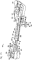
- This section describes an exemplary emulsion formation system 50 including an instrument 52 and a microfluidic cassette 54; see Figs. 1 to 3 .
- Figures 1 and 2 show instrument 52 in respective closed and open configurations.
- the instrument may be described as an emulsification engine or apparatus that drives any combination of fluid flow, droplet generation, emulsion formation, emulsion collection, and emulsion concentration, among others, in cassette 54.
- the instrument may form a seat 56 (interchangeably termed a seating area, a receiving area, or a loading site) at which the cassette may be operatively disposed for interaction with the instrument.
- Figure 3 shows a schematic view of instrument 52 and cassette 54 of system 50, with cassette 54 engaged with seat 56.
- Instrument 52 may be equipped with a fluidics assembly 58 and a drive assembly 60.
- Fluidics assembly 58 may be any mechanism or set of mechanisms that, among others, contains, releases, directs, drives, monitors, regulates, controls, and/or detects fluid, generally, gas and/or liquid, in instrument 52 and cassette 54.
- Drive assembly 60 may be any mechanism or set of mechanisms that drives relative motion of one or more portions of the instrument relative to one another and/or relative to the cassette (or vice versa). In some cases, the fluidics assembly may be engaged with the cassette manually.
- the fluidics assembly may include at least one pressure source 62, such as one or more pumps 64, 66.
- Each pressure source may be a source of positive pressure and/or negative pressure (i.e., a pressure respectively greater or less than atmospheric pressure).
- the fluidics assembly may include a vacuum pump 64 configured to be a source of negative pressure applied to the cassette.
- the fluidics assembly may include a positive pressure pump 66 configured to be a source of positive pressure applied to the cassette.
- the same pump e.g., a reversible pump
- both negative and positive pressure may be applied to the cassette (and particularly to a chip thereof) at the same time.
- Exemplary pumps that may be suitable include diaphragm pumps, syringe pumps, rotary pumps, etc.
- Fluid may be contained in the fluidics assembly by any suitable fluidic containers 68 such as one or more conduits 70 (e.g., tubing), at least one manifold 72, one or more chambers, or any combination thereof.
- the fluidic containers provide a cassette interface structure 74 (such as manifold 72) having one or more ports 76 for fluid communication with the cassette.
- pressure originating from the pressure source may be applied to the cassette via ports 76 of interface structure 74.
- Flow of fluid through the fluidics assembly may be regulated by one or more valves 78-84.
- Each valve may be an on/off valve 78, 80, or a valve that is continuously adjustable.
- the valve may be a continuously adjustable valve 82, 84 that is included in a pressure controller 86, 88 that achieves and maintains pressure at a set point.
- the valve may provide any suitable number of connections to pumps, conduits, ports, and/or vents, such as a two-, three-, or four-way valve, among others.
- Pressure in the fluidics assembly may be measured at any suitable positions therein by one or more pressure sensors 90-94.
- the pressure sensors may include an endpoint pressure sensor 90 configured to detect pressure changes associated with ports 76 and resulting from air intake by channels of cassette 54.
- the sensors also or alternatively may include pressure sensors 92, 94 incorporated into pressure controllers 86, 88, respectively.
- Drive assembly 60 may be configured to drive relative motion, indicated by a double-headed arrow at 100, of manifold 72 (and/or ports 76) and cassette 54 (and/or seat 56).
- the drive assembly first may bring the manifold (and/or ports) and the cassette together, into sealed engagement with one another, to fluidically connect (i.e., create fluid communication between) the manifold/ports and the cassette, for emulsion formation.
- the drive assembly may separate the manifold/ports and the cassette from one other, to break the sealed engagement and terminate the fluid communication.
- the drive assembly may drive motion of the manifold/ports, the cassette (and/or seat), or a combination thereof, in parallel or serially.
- the drive assembly may be equipped with one or more force-generation devices, such as one or more motors 100, 102.
- Each motor may be a rotary motor or a linear motor, among others.
- motor 100 or another force-generation device may drive horizontal motion (of the manifold/ports and/or cassette/seat), and motor 102 or another force-generation device may drive vertical motion (of the manifold/ports and/or cassette/seat).
- the manifold/ports and/or the cassette/seat are driven only vertically relative to each other.
- Each motor may be connected to a respective carriage 104, 106 via a power train that includes one or more linkages 108, 109, which may include one or more racks, gears, pulleys, cables, lead screws, and/or the like.
- Each carriage may carry and/or support any suitable combination of components of fluidics assembly 58 and/or a door of the instrument (see below).
- one or more carriages may carry manifold 72/ports 76, and/or one or more carriages may carry cassette 54 (and seat 56).
- both carriages may carry manifold 72/ports 76 or both may carry cassette 54 (and seat 56).
- one carriage may carry manifold 72/ports 76 and another carriage may carry cassette 54 (and seat 56).
- Drive assembly 60 also may be equipped with one or more sensors 110, which may, for example, be position sensors, such as rotary or linear encoders.
- the position sensors may measure the position and/or velocity of one or more drive assembly components, such as the motors and/or the carriages, among others.
- Instrument 52 may incorporate any number of additional sensors, such as cassette sensors 114, 116 and/or an endpoint sensor 117.
- sensors 114, 116, 117 may be associated with cassette 54, seat 56, and/or manifold 72/ports 76, among others.
- Each additional sensor may be an optical sensor, an electrical sensor, or the like.
- the sensor may detect an aspect of the cassette itself, liquid held by the cassette, and/or fluid in contact with the liquid. For example, each sensor may detect whether or not a component of the cassette is loaded in the instrument, whether or not fluid has been loaded properly in the cassette, whether or not an emulsion has been formed, whether or not liquid has been depleted from a container of the cassette, or the like. Further aspects of endpoint sensors 117 are described below in Section VI.
- the instrument may include a processor 120 programmed to control and coordinate operation of other instrument components.
- the processor may be or include any suitable combination of electronic devices or components that send and receive signals and, optionally, manipulate data, in analog and/or digital form.
- the processor may be in communication with fluidics assembly 58, drive assembly 60, sensors 114-117, and a user interface 122, among others. Accordingly, the processor may be configured to control any combination of pumps 64, 66, pressure controllers 86, 88, valves 78, 80, motors 100, 102, and the like.
- User interface 122 may include any mechanism or set of mechanisms for receiving inputs from a user and/or communicating outputs to the user.
- the interface may include any suitable input device(s), such as a button, a lever, a knob, a mouse, a joystick, a keypad, a touchscreen, a keyboard, a data port, etc.
- the interface also or alternatively may include any suitable output device(s), such as one or more status lights, a display or screen, a printer, a data port, and/or the like.
- Figure 1 shows an exemplary embodiment of user interface 122.
- the user interface may have a single input device, namely, a button 124 provided on an exterior of the instrument, in this case, on a door 126.
- Button 124 (or another user control) may be connected to a switch 128 operated by pressing the button. Pressing the button when the door is closed, as in Fig. 1 , may signal the processor to open (and/or unlock) the door via the drive assembly. Pressing the button when the door is open, as in Fig. 2 , may signal the processor to close (and, optionally, lock) the door via the drive assembly.
- the processor may proceed, without further user input or participation, to initiate and control a sequence of operations by the drive assembly and fluidics assembly that cause emulsion formation and, optionally, emulsion concentration, in the cassette.
- the user interface of instrument 52 also may include one or more indicator lights 130-136 that may communicate a status of the instrument to the user.
- indicator light 130 may be visible through button 124.
- Other indicator lights 132-136 may be supported by a body or housing 138 of the instrument. The indicator lights may communicate a status such as (a) emulsion formation in progress, (b) cassette not seated in instrument, (c) cassette is seated, (d) gasket missing, (e) door is locked, or the like.
- Figures 1 and 2 respectively show instrument 52 in a closed configuration and an open configuration.
- Housing 138 and door 126 collectively may form a chamber 140 in which seat 56 may be disposed .
- the position of door 126 may determine the closed or open configuration of the instrument.
- door 126 retracts into chamber 140 to permit access to seat 56.
- the door may move translationally when the instrument opens to decrease the size of chamber 140, such that seat 56 is disposed outside rather than inside the chamber.
- Door 126 may function as a barrier that protects internal components of the instrument.
- instrument 52 e.g., fluidics assembly 58, drive assembly 60, processor 120, etc.
- instrument 52 e.g., fluidics assembly 58, drive assembly 60, processor 120, etc.
- cleaning agents such as bleach
- the door may move pivotally or both pivotally and translationally between open and closed configurations.
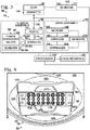
- This section describes exemplary microfluidic cassette 54 that interfaces with instrument 52; see Figs. 4 and 5 .
- Figures 4 and 5 shows cassette 54 supported by and engaged with seat 56 of instrument 52.
- the cassette may be any device or assembly configured to be operatively and removably engaged with instrument 52.
- the cassette may be configured to be readily received by and removed from instrument 52 and is interchangeable with other cassettes.
- a user may use a set of cassettes each of which can be disposed interchangeably in seat 56, for emulsion formation with the cassettes serially.
- Cassette 54 may include a cartridge 150, a microfluidic chip 152 (see Fig. 4 ), and a gasket 154 (see Fig. 5 ).
- Cartridge 150 also termed a chip holder, may be configured to support and position the chip, and in some cases, may lock the chip reversibly to the cartridge.
- the cartridge may be reusable because the cartridge does not contact any liquid loaded into and driven within microfluidic chip 152. (The instrument may not contact any of the liquid either.)
- the cartridge may have any suitable size and shape.
- the cartridge may have a larger footprint than the chip, such as being wider and/or longer than the chip, to facilitate handling by a user.
- the cartridge may elevate the chip from a bottom surface of the cartridge. The cartridge thus may (or may not) have a greater height than the chip.
- the cartridge may be shaped to mate with seat 56.
- seat 56 may be at least generally complementary to the cartridge, such as including an at least generally cartridge-shaped depression 156 formed in a floor 158 of the chamber of the instrument. Depression 156 may have corner wall regions 160 that restrict horizontal motion of the cartridge.
- the depression may have one or more sloped wall regions 162 that facilitate the ability of the user to grasp the cartridge as the cartridge is being placed manually into the depression and/or removed from the depression.
- seat 56 may project upward from floor 158.
- cartridge 150 and seat 56 may be configured such that the cartridge can be installed in only one orientation, to avoid application of pressure by instrument 52 to the wrong parts (e.g., the wrong row of wells) of the microfluidic chip.
- cartridge 150 is generally trapezoidal in shape.
- Cartridge 150 also may attach gasket 154 to the cassette (see Figs. 4 and 5 ).
- the cartridge may form a plurality of projections, such as hooks 164 or pins, that are configured to be received in apertures 166 of the gasket (see Fig. 5 ).
- Microfluidic chip 152 may form a plurality of wells 168-172 that serve as input containers for prospective emulsion phases and output containers for collected emulsions (see Fig. 4 ). The chip is described in more detail below in Section III.
- Figure 5 shows gasket 154 attached to cartridge 150.
- the gasket may be used for emulsion formation only once (i.e., a disposable gasket) or may be used more than once (i.e., a reusable gasket).
- the gasket may include a substantially planar sheet 174 formed of a conformable and/or resilient material, such as an elastomer (e.g., silicone rubber).
- the sheet may be sized to cover at least a portion of the chip, such as to at least partially cover any suitable number of the wells of the chip. At least partially covering the wells may limit inadvertent introduction of contaminants into the wells and/or cross-contamination between wells.
- the sheet may define apertures 166 at opposing ends and/or sides of the sheet, and an array of orifices 176 (interchangeably termed through-holes) that are arranged in correspondence with wells 168, wells 170, and/or wells 172 of chip 152 (also see Fig. 4 ).
- orifices 176 may have the same spacing as the wells and may be alignable (e.g., coaxially) with any number of the wells, such that each of wells 168, each of wells 170, and/or each of wells 172 is overlapped by a different orifice.
- Each orifice may (or may not) be smaller in diameter than the (inner) diameter of an overlapped well.
- each orifice may overlap only one well or may be large enough to overlap two or more wells (e.g., overlapping a row or column of wells, among others).
- the orifice may function as a vent during emulsion formation and/or emulsion concentration and/or may provide fluid communication between ports of the instrument and wells of the chip.
- the gasket When the gasket is operatively disposed on and engaged with the chip, the gasket may be configured to form a circumferential seal with any of the wells of the chip, such as each of wells 168, 170, and/or 172.
- Exemplary sizes for orifices 176 include a diameter of about 0.2, 0.5, 1, 2, 3, or 5 mm, among others, or less than about one-half of the outer or inner diameter of each corresponding well.
- the gasket may be a separate piece from the chip or may be integral to the chip. If integral, the gasket may be substantially permanently attached to the containers of the chip, such that the containers and the gasket cannot be separated from each other without damaging the chip (i.e., the chip has a unitary structure that includes a gasket).
- the gasket may be co-molded with the containers of the chip or may be formed separately and attached permanently to the chip, such as with an adhesive, by bonding, or the like.
- the gasket may be formed as a plurality of spaced annuluses of elastomeric material disposed on and/or permanently attached to the top surface of the desired containers of the chip, such as each of the output wells. Each annulus may be coaxial with a container of the chip.
- the gasket may include a thin sheet or layer of filter paper.
- the filter paper may be disposed on the resilient sheet and/or may be sandwiched between a pair of resilient sheets to encapsulate the filter paper, among others. In any event, the filter paper may overlap/cover each of the orifices of the sheet.
- the filter paper may have a pore size selected to reduce particulates from being drawn into the manifold and/or entering containers of the chip from the ambient environment and/or the manifold. The filter paper may reduce contamination. The pore size may be selected such that air flow, venting and/or pressure in the chip and instrument are not affected substantially or adversely.
- the filter paper may be chosen to be hydrophobic or oleo/hydrophilic, to minimize contamination with, and/or passage into the manifold of, hydrophilic/aqueous or oleo/hydrophobic fluids, respectively.
- This section describes exemplary microfluidic chip 152 that may be utilized in cassette 54 to form and collect one or more emulsions; see Figs. 6 to 11 .
- microfluidic chip in the present disclosure describes any device for holding and manipulating fluids, such as prospective and actual emulsion phases.
- the device may not (or may) include electrical and/or electronic structure.
- microfluidic chip and “microfluidic device” are interchangeable.
- microfluidic means that the chip/device defines at least one channel with a characteristic dimension (e.g., diameter, width, and/or depth) of less than one millimeter.
- a microfluidic chip is not limited otherwise in size, shape, or functionality, except when expressly specified.
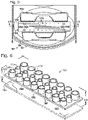
- FIG. 6 shows an exploded view of chip 152.
- the chip may be used for emulsion formation only once (i.e., a disposable chip) or may be used more than once (i.e., a reusable chip).
- the chip may be composed of an upper member 180 and a lower or sealing member 182.
- the upper and lower members may be substantially irreversibly attached to each other, such as by bonding and/or with an adhesive.
- the chip may have a unitary (one-piece) structure, meaning that the chip cannot be separated into two or more pieces without damaging the chip, such as by cutting, breaking, tearing, melting, dissolving, etc.
- Upper member 180 may form a bottom region or base 184 and a plurality of tubular projections 186 projecting upward from the base.
- Each tubular projection may form lateral side walls 188 of one of wells 168-170.
- Lower member 182 which may or may not be a substantially featureless sheet of material or film, may seal a bottom surface 190 of upper member 180.
- lower member 182 may form a bottom wall of each of wells 168-172 and each channel (see below).
- Figures 7 and 8 show respective plan and sectional views of chip 152.
- the chip may provide a plurality of containers 192, such as chambers, wells 168-172, or the like, for holding emulsion phases.
- a subset of the containers such as input wells 168, 170 (also termed inlet wells), may provide input reservoirs 194, 196 to receive and hold prospective emulsion phases, and to supply the emulsion phases to one or more droplet generators 198 of the chip.
- Another subset of containers 192 such as output wells 172 (also termed outlet wells), may provide output containers to receive and collect one or more emulsions from droplet generators 198.
- Chip 152 may provide one or a plurality of emulsion formation units 200 each including a droplet generator 198 (see Fig. 7 ).
- Units 200 may be substantially identical to one another.
- the emulsion formation units may be in fluid isolation from each other, such that there is no sharing or mixing of emulsion phases among the units, or may share an input reservoir (such as for a continuous phase). In any event, the units may be used to form a corresponding plurality of separate emulsions collected in the output containers (e.g., wells 172).
- Containers 190 structured as wells 168-172 may have any suitable arrangement.
- the wells may be arranged in rows and columns.
- each column (or row) may be part of a different emulsion formation unit 200.
- the wells may be spaced in correspondence with a standard well-to-well spacing of a microplate, as published by the American National Standards Institute (ANSI) on behalf of the Society for Biomolecular Screening.
- ANSI American National Standards Institute
- the wells within each row may have a center-to-center spacing of about 18, 9, 4.5, 2.25, or 1.125 millimeters, among others.
- the wells of the same emulsion formation unit e.g., the wells of a column
- Wells 168-172 may have any suitable size and shape.
- each of the wells in a row may be substantially identical to each other, having the same size, shape, and volume.
- Wells of different rows and/or within the same column may have different sizes, shapes, and/or volumes.
- the wells may be configured to form a seal when juxtaposed with a suitably formed gasket.
- the top surface of each well may be substantially planar.
- the top surfaces of wells may be coplanar to enable forming a seal with a substantially planar gasket.
- wells 172 are largest, wells 168 are intermediate in size, and wells 170 are smallest.
- Each well may taper toward a base 202 of the chip (see Fig. 8 ).
- the wells of a row and/or all of the wells may have the same height, to form a planar top surface 204 of the chip.
- the top surface may be engaged with gasket 154 (e.g., see Fig. 5 ).
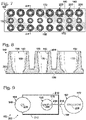
- Figure 9 shows a somewhat schematic bottom view of a single emulsion formation unit 200 of chip 152.
- Input reservoirs 194, 196 i.e., wells 168, 170
- Collection container 192 may receive and collect an emulsion 209 formed by droplet generator 198 from oil phase 206 and sample 208.
- the reservoirs and the collection container may be fluidically interconnected via channels 210-216 that intersect at droplet generator 198.
- the channels may include one or a pair of oil inlet channels 210, 212, a sample inlet channel 214, and an emulsion outlet channel 216.
- each of oil inlet channels 210, 212 may extend from a different input reservoir.
- the emulsion formation unit may include only one oil inlet channel.
- Exemplary emulsion phases and other exemplary configurations for droplet generators, channels, input reservoirs, and collection containers, among others, that may be suitable for chip 152 are described in the patent documents listed above under Cross-References, which are incorporated herein by reference, particularly U.S. Patent Application Publication No. 2010/0173394 A1, published July 8, 2010 ; U.S. Patent Application Publication No. 2011/0217712 A1, published September 8, 2011 ; and PCT Patent Application No. WO 2011/120024, published September 29, 2011 .
- Figures 10 and 11 show less schematic, bottom views of emulsion formation units 200 ( Fig. 10 ) or one of the units ( Fig. 11 ) of chip 152 in the absence of lower member 182 (also see Fig. 6 ).
- Channels 210-216 and droplet generator 198 of each unit 200 may be formed predominantly in bottom surface 190 of upper member 180, with only a bottom wall of each channel and droplet generator formed by lower member 182. In other embodiments, at least a portion of one or more of the channels and/or the droplet generator of each unit 200 may be formed in the top surface of lower member 182.
- Channels 210-216 may have different cross-sectional sizes (i.e., diameters/widths and/or depths) and/or lengths and/or may vary in size along each channel.
- the cross-sectional size(s) and the lengths may be selected to provide a desired resistance to flow and thus a desired ratio of emulsion phases flowing through droplet generator 198, to form droplets of the desired size, to enhance droplet stabilization after droplet formation, to form at least one air trap 218 in an inlet channel (e.g., sample inlet channel 214), or any combination thereof, among others.
- channels 210-216 form a channel network that interconnects the wells of an emulsion formation unit.
- the channel network may have a narrower/shallower region 220 for greater flow resistance, and a wider/deeper region 222 downstream of region 220 for droplet formation and stabilization.
- the cross-sectional size of the channel network may increase toward the collection container of the unit.
- Region 222 may begin upstream of droplet generator 198 for each of the inlet channels and may extend from the droplet generator via outlet channel 216.
- Each channel may taper in a direction parallel to the depth axis of the channel. For example, each channel may taper toward the top (or the bottom) of the chip.
- each channel may have a trapezoidal cross-sectional shape and/or may have a depth and a width that are about the same.
- channel portions of region 220 may have a depth and a width of about 50-100, or 60-80 micrometers, among others
- channel portions of region 222 may have a width and a depth of about 80-150 or 90-120 micrometers, among others
- the droplets generated may have a volume of about 0.1-10 nanoliters, among others.
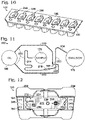
- This section describes exemplary cartridge 150 of cassette 54 for holding the microfluidic chip and the gasket; see Figs. 12 and 13 . Additional aspects of the cartridge are described above in Section II (e.g., see Figs. 4 and 5 ).
- FIG 12 shows cartridge 150 in an open or receiving configuration (compare with Fig. 4 ).
- the open cartridge forms a receiving area 230 sized to receive chip 152 from above the cartridge.
- the receiving area may include a beam or central portion 234 that supports the chip and a pair of retainers 236, 238 with an adjustable spacing.
- Beam 234 (and/or the retainers) may define one or more openings 239 for mating with seat 56 of instrument 52 (see Section V).
- the beam can be constructed to ensure level presentation of the chip to the manifold for making a solid, uniform seal across all containers in contact with manifold.
- An exemplary material for the beam is stainless steel.
- the cartridge may be equipped with an optical element 240, which may be reflective or otherwise detectable optically.
- the optical element may be on a surface of the cartridge, such as an upwardly, downwardly, or laterally facing surface.
- the optical element is disposed on a floor 242 of the receiving area.
- the cartridge also or alternatively may be equipped with a contact element 244 (also see Fig. 13 ), which may be electrically conductive.
- conductive element 244 is disposed on an underside of the cartridge, such as on a bottom surface of beam 234 (and/or one of retainers 236, 238). The conductive element may be used to detect that the cartridge is seated in place within the receiving area.
- Retainers 236, 238 may form retaining structure for chip 152 and gasket 154.
- each retainer may provide an undercut wall 246, 248 capable of projecting over and overlapping a region of base 202 of chip 152 (e.g., also see Figs. 7 and 8 ).
- Each wall 246, 248 may define notches 250 capable of receiving a column of wells 168-172 disposed near an end of the chip.
- each retainer may provide one or more projections, such as hooks 164 or pins, to receive the gasket.
- Figure 13 shows an exploded view of cartridge 150.
- Beam 234 may form lateral tracks 252 that allow the beam to be slidably mated with each retainer 236, 238.
- Spring-loaded pins 254, 256 may restrict separation of the beam from the retainers after they have been mated.
- Retainers 236, 238 may be biased toward the open configuration of Fig. 12 by one or more biasing elements, such as springs 258 that urge the retainers apart.
- the retainers may be urged together and fastened to each other in a closed configuration with a fastening mechanism 260 formed on one or both sides of the retainers.
- the fastening mechanism may include a tab 262 of one retainer received in a slot 264 of the other retainer.
- the fastening mechanism on each side may be released by pressing a respective button 266 operatively coupled to tab 262.
- the cartridge may be opened by squeezing the cartridge at the buttons.
- the button(s) can be placed centrally or off-center, among others.
- the cartridge may include hinged clamps that fasten the chip to the support beam at the ends (or sides) of the cartridge, with retainer walls along the top and bottom sides, that is, no buttons or fasteners at the top and bottom.
- the clamps can be made with features (e.g., notches 250) that match the shapes of the outer surface of the wells on the left and right sides of the chip in the cartridge for additional restriction of motion and clamping efficiency.
- This section describes an exemplary seated configuration for the cassette in the instrument, and sensors of the instrument that may detect the seated configuration; see Figs. 14 and 15 .
- FIG 14 shows seat 56 of instrument 52, without cassette 54 (compare with Fig. 4 ).
- Seat 56 may include a platform 280 that provides one or more pins 282 for mating with cartridge 150.
- Platform 280 also may provide electrodes 284 of cassette sensor 114 (also see Fig. 3 ) to detect contact of seat 56 with the cartridge.
- FIG 15 shows a sectional view of cassette 54 and seat 56 taken with the cassette operatively disposed in instrument 52.
- Housing 138 of the instrument may include an exterior housing portion 286, a base plate 288, and an interior housing portion 290.
- the interior housing portion may at least partially define chamber 140 of the instrument (e.g., see Figs. 1 and 2 ) and may form at least a portion of seat 56.
- Platform 280 may be secured to the housing, such as to base plate 288, with fasteners 292.
- Cartridge 150 of the cassette may be mated with platform 280.
- the cartridge may define a recess 294 that receives a body of the platform, and/or pins 282 of the platform may be received in openings 239 of the cartridge.
- Contact element 244 may be engaged with electrodes 284, which allows the instrument to detect that the cartridge is properly positioned in the instrument by engagement with seat 56.
- Cassette sensor 116 may be positioned adjacent the cassette, such as supported by manifold 72 above the cassette, to detect optical element 240 of the cartridge.
- Sensor 116 may include a light source to illuminate the optical element with incident light, and a photosensor to detect light reflected by the optical element.
- Chip 152 may be sufficiently translucent to permit passage of incident and reflected light.
- gasket 154 may be sufficiently opaque to block passage of the incident light, without substantially reflecting the incident light back to the photosensor. Accordingly, through the use of cassette sensors 114, 116, the instrument may determine whether the cartridge is loaded and seated in the instrument, and, if seated, whether the gasket is present.
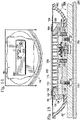
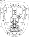
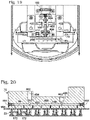
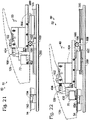
- This section describes exemplary structure of fluidics assembly 58 of instrument 52 and exemplary operation of the fluidics assembly on cassette 54 to form and concentrate emulsions; see Figs. 16 to 20 .
- Figure 16 shows a schematic view of fluidics assembly 58 operatively interfaced with chip 152 via cassette interface structure 74, namely, manifold 72 with ports 76. Each port may be fluidically connected to one or more wells 172 of chip 152. Pressure may be applied to the chip with a negative pressure portion 300 and a positive pressure portion 302 of the fluidics assembly. For example, negative pressure may be applied first by negative pressure portion 300 to form a set of emulsions that are collected in wells 172. Then, the emulsions may be concentrated with application of positive pressure by positive pressure portion 302. In some cases, positive pressure may be applied to the chip to drive emulsion formation.
- positive pressure may be applied to input wells 168, 170 to drive droplet generation and emulsion collection.
- both negative pressure and positive pressure may be applied to the chip to drive emulsion formation.
- negative pressure may be applied to output wells 172 and positive pressure may be applied at the same time to at least a subset of the input wells (such as each of wells 168 or each of wells 170).
- a first pressure drop may be formed between the oil input wells and the output wells and a second pressure drop may be formed between the sample input wells and the output wells.
- the magnitudes of the pressure drops may be set or adjusted to achieve desired relative and/or absolute flow rates for the oil phase and the sample.
- Each of pressure portions 300, 302 may include a respective pump 64 or 66 and a respective pressure controller 86 or 88.
- a pump may be used with two controllers, e.g., with another valve included between the pump and the controllers.
- the pump may act as a source of negative or positive pressure for the pressure portion, and the pressure controller may adjust the level of negative or positive pressure in a reservoir or region of the pressure portion, in order to adjust the level of pressure applied to chip 152.
- the pump may be fluidically isolated from the chip and/or not pumping fluid when the pressure is applied to the chip.
- the pump may be used as a source of pressure to establish a positive or negative pressure in a reservoir, and then the established pressure may be applied to the chip from the reservoir without any further participation of the pump.
- Each pressure controller may include a respective valve 82 or 84, a respective pressure sensor 92 or 94, and a control device 304 or 306 (e.g., a proportional (P) controller, a (PI) proportional-integral controller, a proportional-integral-derivative (PID) controller, or the like).
- Each pressure controller may form a feedback loop.
- the control device may receive a value for a set point pressure and may operate the valve of the controller based on signals received from the sensor to achieve and maintain the set point pressure.
- the sensor of the pressure controller may detect pressure at a position that is fluidically closer to the chip (or fluidically closer to the pump) than the controller's valve.
- Each pressure portion also may include a first pressure reservoir disposed fluidically between the pump and the pressure controller.
- the first reservoir may be a chamber and/or may be a conduit 312 or 314 that provides fluid communication between a pump and its respective controller.
- Conduits 312, 314 or other first reservoirs may (or may not) be of substantially larger diameter and/or volume than any combination of conduits 316-322 disposed fluidically closer to the chip.
- the inner diameter of either or both of conduits 312, 314 or any other first reservoirs may be at least about 2, 5, or 10 times the inner diameter of any of conduits 316-322, and especially conduits 318, 320.
- the volume of either or both of conduits 312, 314 or any other first reservoirs may be at least about 10, 20, 50, or 100 times the volume of any combination of conduits 316-322, and especially conduits 318, 320.
- the pressure portion also or alternatively may include a second pressure reservoir disposed fluidically between the pressure controller and the chip.
- the second reservoir may be a chamber and/or may be a conduit 316 or 322 that provides fluid communication between a pressure controller and a valve 78 and/or 80 disposed fluidically between the pressure controller and the chip. If both first and second reservoirs are present in a pressure portion, the first reservoir may (or may not) have a substantially larger volume than the second reservoir, such as at least about 2, 5, 10, 20, or 50 times the volume of the second reservoir.
- conduits 316, 322 or other second reservoirs may (or may not) be of substantially larger diameter and/or volume than any combination of conduits 318, 320 disposed fluidically closer to the chip.
- the inner diameter of either or both of conduits 316, 322 or any other second reservoirs may be at least about 2, 5, or 10 times greater than the inner diameter of conduits disposed fluidically closer to the chip, and especially conduits 318, 320.
- the volume of either or both of conduits 316, 322 or any other second reservoirs may have at least about 10, 20, 50, or 100 times greater than the volume the fluidics assembly disposed fluidically between either conduit and the chip, such as the volume enclosed by conduits 318, 320.
- isolatable pressure reservoirs allows a reservoir to be charged with positive or negative pressure from a pump and/or a larger reservoir.
- the pressure may be stored (e.g., briefly) in the reservoir, in isolation from the pump, the chip, and/or an adjacent reservoir.
- the stored pressure then may be shared with another reservoir and/or the chip, without substantial diminishment of the magnitude of the stored pressure, if the volume in which the pressure is stored is not increased substantially when the stored pressure is placed in fluid communication with another volume of the pressure portion.
- Fluidics assembly 58 may be operated as follows in response to a signal to form emulsions.
- Vacuum pump 64 may be turned on.
- Conduit 312 i.e., a first reservoir
- a negative pressure such as about - 7 psi (--48 kPa (kilopascals)).
- Pump 64 may (or may not) be turned off.
- a check valve in or adjacent the pump may prevent loss of negative pressure from the first reservoir through the pump.
- Negative pressure controller 86 may establish a negative pressure in conduit 316 (i.e., a second reservoir) according to a set point, such as a negative pressure of less than about -10 psi (--69 kPa) (e.g., about -0.5 to -4.5 psi (--3.4 to -31.5 kPa).
- a set point such as a negative pressure of less than about -10 psi (--69 kPa) (e.g., about -0.5 to -4.5 psi (--3.4 to -31.5 kPa).
- One or both of valves 78, 80 may be adjusted to provide fluid communication among conduits 316-320 and manifold 72, such that the negative pressure is applied to wells 172.
- the negative pressure may be applied with the pump inactivated, that is, with the pump turned off (not pumping fluid) and/or not fluidically connected to the chip.
- the pressure controller may continue to control the pressure applied to the chip after fluid communication is created with the chip, or the pressure controller also may be shut off and/or fluidically isolated.
- Endpoint sensor 90 may monitor the pressure applied to the chip by detecting a corresponding pressure in the fluidics assembly, such as in manifold 74 and/or near ports 76, to allow the instrument to determine when to terminate application of negative pressure.
- the pressure detected by sensor 90 may be equivalent to the applied pressure or may differ from the applied pressure by a pressure differential caused by resistance to fluid flow between the chip and pressure sensor.
- valve 78 may be adjusted to fluidically isolate conduits 318, 320 and ports 76 from conduit 316, while fluidically connecting the conduits and ports to a vent 324.
- the detected pressure (e.g., at the manifold) can be used to maintain a predefined pressure range of applied pressure (e.g., +/-0.05, +/-0.075, +/- 0.1, +/-0.25, +/- 0.5 psi, etc.).
- a predefined pressure range of applied pressure e.g., +/-0.05, +/-0.075, +/- 0.1, +/-0.25, +/- 0.5 psi, etc.
- Control of this pressure at the point of emulsion generation may influence the degree of monodispersity of the formed emulsion. Tighter control of pressure may give higher monodispersity (more uniform emulsion droplet size).
- Positive pressure pump 66 then may be turned on, and conduit 314 (i.e., a first reservoir) may be charged to a positive pressure, such as about 5-8 psi (-34 to 55 kPa). Pump 66 may (or may not) be turned off. A check valve in or adjacent the pump may prevent loss of positive pressure from the first reservoir through the pump. Positive pressure controller 88 may establish a positive pressure downstream in conduit 322 (i.e., a second reservoir) according to a set point, such as a positive pressure of less than about 10 psi (-69 kPa) (e.g., about 0.5 to 10 psi (-3.4 to 69 kPa)).
- Valve 80 (and/or valve 78) may be adjusted to provide fluid communication among conduits 320, 322 and manifold 72, such that the positive pressure is applied to wells 172.
- the positive pressure may be applied with the pump inactivated, that is, with the pump off and/or not fluidically connected to the chip.
- the pressure controller may continue to control the pressure applied to the chip after fluid communication is created with the chip or the pressure controller also may be shut off.
- valve 80 may be adjusted to fluidically isolate conduit 320 and ports 76 from conduit 322, while fluidically connecting conduit 320 and the ports to vent 324.
- the conduits flanking the pressure controllers may function as reservoirs, as described above.
- Each reservoir may have a volume that is substantially greater than the volume of conduits 318 and/or 320 and the channels of the manifold, such that the reservoir can apply pressure to the chip after inactivation of the pump, that is, when the pump is isolated from downstream conduits and/or turned off.
- a stored negative and/or positive pressure e.g., stored as a gas volume with a positive or negative pressure in conduits 312 and/or 316 and 314 and/or 322
- a more uniform and reproducible pressure can be applied, which may produce better emulsion formation.
- Figure 17 shows a flowchart illustrating exemplary formation and concentration of an emulsion with emulsion formation system 50.
- the procedures illustrated in the flowchart may be performed in any suitable order and combination.
- Microfluidic chip 152 may be selected, indicated by 340.
- the chip may be assembled with cartridge 150, and optionally locked to the cartridge.
- Prospective emulsion phases 206, 208 may be dispensed respectively to wells 168 and wells 170 of the chip, indicated by an arrow at 342, to produce a phase-loaded configuration 344 of the chip.
- the same prospective emulsion phase 206 e.g., a prospective continuous phase, such as an oil phase including surfactant(s)
- the same or different prospective phases 208 e.g., prospective dispersed phases, such as different aqueous samples
- prospective dispersed phases such as different aqueous samples
- the aqueous samples may contain salts, surfactant(s), and biological components, such as enzymes, proteins, dNTPs, and/or other polymerase chain reaction constituents, among others.
- Dispensing phases into each of wells 168 and/or into each of wells 170 may be performed in parallel (such as with a multichannel pipette) or in series.
- at least about twice the volume of oil phase 206 relative to sample phase 208 may be disposed in the wells.
- about 10-200 microliters of oil phase 206 may be disposed in each of wells 168 and about 5-100 microliters of sample phase 208 in each of wells 170.
- wells 172 may (or may not) be empty at this point.
- Further aspects of prospective emulsion phases that may be suitable for forming emulsions are described in the patent documents listed above under Cross-References, which are incorporated herein by reference, particularly, U.S. Patent Application Publication No. 2011/0217712 A1, published September 8, 2011
- Negative pressure may be applied to the chip at wells 172, indicated by an arrow at 346.
- Gasket 154 may be disposed on the chip, manifold 72 engaged with the gasket, and negative pressure applied to chip 152 at wells 172 via negative pressure portion 300 of the fluidics assembly of the instrument.
- An emulsion 348 of droplets 350 composed of phase 208 and disposed in continuous phase 206, may be created at each droplet generator and collected in each well 172, to produce a phase-processing configuration 352, during which all of wells 168, 170 still contain sufficient fluid for further emulsion formation.
- Droplets 350 may be buoyant (or may sink) in the continuous phase and thus may float upward (or sink downward) and accumulate in an upper (or lower) region of the emulsion.
- positive pressure applied to wells 168, 170 may drive emulsion formation.
- Endpoint sensor 90 may monitor a pressure of negative pressure portion 300 as emulsion formation is occurring, such as in configuration 352. Use of an endpoint sensor enables a majority (greater than one-half) of each sample to be converted to an emulsion. Sensor 90 generally monitors a pressure in or near the manifold, to detect a change in the pressure indicating depletion of liquid (phase 206 and/or 208) from one or more of wells 168, 170 (i.e., one of the input wells is empty).
- the change may meet a predefined condition corresponding to a pressure change indicative of air intake from a well (168 or 170), into one or more channels, through a droplet generator, into and/or through an output well (172), into the manifold, or any combination thereof.
- the change may be a drop in the level of vacuum that occurs for at least a predefined amount of time, to at least a predefined level, at at least a predefined rate or acceleration, any combination thereof, or the like.
- the pressure sensor can detect the pressure change indicative of air intake if only one of the inlet wells 168, 170 is empty.
- the wells are loaded such that the sample wells empty first, so, everything else being equal, a sample well loaded with the smallest volume of sample may determine when the endpoint of droplet generation occurs.
- an alternative or additional endpoint sensor 117 may be included in the instrument or cassette (see Fig. 3 ).
- the endpoint sensor may detect and/or monitor an aspect of fluid (liquid and/or gas) in the chip and/or of fluid in contact with fluid in the chip.
- the endpoint sensor may detect an aspect of fluid disposed in one or more containers/wells of the chip, such as sample containers/wells of the chip.
- the endpoint sensor may detect the aspect for at least one or each of the sample containers/wells, at least one or each of the oil containers/wells, at least one or each of the emulsion containers/wells, or any combination thereof.
- the endpoint sensor may detect heat capacity of the fluid disposed in one or more containers/wells of the chip.
- the heat capacity may have a higher value when liquid is present in the containers/well and then may change substantially when the liquid is replaced with air, that is, when a container/well is emptied of its liquid.
- the endpoint sensor may include a plurality of hot wire sensors configured to sense heat capacity of fluid in each of the sample wells, each of the oil wells, and/or each of the output wells of the chip.
- the endpoint sensor may be an optical sensor that detects an optical characteristic that changes as the endpoint is reached.
- the optical sensor may detect refractive index, fluorescence (e.g., if a fluorophore is present in and/or is added to at least one of the prospective emulsion phases), absorbance, scattering, reflectance, or the like, of fluid (liquid and/or gas) in one or more input (and/or output) containers/wells of the chip.
- the optical characteristic changes, until a change that meets a predefined condition has occurred (e.g., the refractive index changes when air replaces liquid in an input container/well, the fluorescence intensity decreases to a predefined level when a fluorophore in a prospective emulsion phase is emptied from an input well (or accumulates in an output well), or the like).
- the endpoint sensor may include an optical detector configured to monitor an optical characteristic for each sample well, each oil well, and/or each output well of the chip, to detect a change in one or more of the wells that meets a predefined condition.
- detection of the change causes the instrument to terminate application of negative pressure to wells 172, indicated by an arrow at 354 and illustrated in configuration 356.
- An empty well 170 is indicated at 358, and air bubbles 360 traveling upward through emulsion 348 are illustrated.
- Application of pressure may be stopped at any suitable endpoint.
- the application of pressure may be stopped when greater than 50%, or at least about 60%, 70%, 80%, or 90%, on average, of each sample has been converted to droplets.
- the application of pressure may be stopped after air has followed liquid into at least one channel, channel network, and/or droplet generator of the chip, but before the air has followed liquid into all of the output containers (e.g., each of wells 172) of the chip.
- the instrument may stop applying pressure to the chip during emulsion formation if the detected pressure is not within a predefined range of the set point pressure. This may provide an important control process that is useful when monodisperse droplets are needed.
- collected emulsion 348 may be left in a resting or packing configuration 362 at atmospheric pressure, indicated by an arrow at 364.
- droplets 350 may be permitted to pack themselves together more closely at the top of the emulsion, to produce a close-packed arrangement 366 of droplets.
- the droplets may be permitted to float upward and pack together more tightly for any suitable time period, such as at least about 1, 5, 10, 30, or 60 seconds, among others.
- a lower, substantially droplet-free portion 368 of the continuous phase may be produced in the bottom region of the emulsion. In some cases, the droplets may pack together at the bottom of the container, if the droplets are more dense than the continuous phase.
- Positive pressure may be applied to wells 172 (or negative pressure to wells 168, 170), indicated by an arrow at 370 and illustrated in configuration 372.
- the positive pressure may drive continuous phase 206 selectively, relative to the phase 208 and/or droplets 350, from emulsion 348, in reverse along the flow path between each output well 172 and input wells 168, 170.
- removed volumes 374, 376 of phase 206 may be collected in wells 168 and/or 170, and emulsion 348 may become more concentrated (i.e., the volume fraction of droplets in wells 172 may be increased and the volume fraction of the continuous phase may be decreased.)
- the positive pressure may be applied for a preset length of time.
- the positive pressure may be applied for a length of time that is determined with an algorithm, based on the length of time that negative pressure was applied to wells 172.
- the positive pressure may be applied for a length of time that is proportional to the duration of emulsion formation.
- the pressure that concentrates the emulsion may be constant (i.e., a single pressure) or ramped (i.e., a gradient pressure) in one or more timed steps.
- Figure 18 shows a plan view of selected aspects of system 50, with cassette 54 seated in instrument 52, and manifold 72 operatively engaged with the cassette. Exterior housing portion 286 is shown in phantom outline. All components are attached to and/or supported by base plate 288.
- Fluidics assembly 58 of Fig. 16 is shown in more detail here.
- the left side of the instrument may provide negative pressure portion 300, and the right side may provide positive pressure portion 302, or vice versa, among others.
- Pumps 64, 66 may be mounted near the rear of the instrument and each may be connected fluidically to conduit 312 or 314 and to a respective vent 390, 392.
- the pumps may be mounted with vibration isolation (e.g., via elastomeric grommets).
- Valves 78, 80 may be mounted to carriage 104 of drive assembly 60, such that the valves can be moved forward and backward in the instrument in response to operation of motor 100.
- Conduits 316-322 may be connected to valves 78, 80 and pressure controllers 86, 88 in the manner described for Fig. 16 .
- Drive assembly 60 may use motors 100, 102 respectively to drive forward-and-backward and up-and-down motion of manifold 72.
- Motor 100 may drive the manifold parallel to a horizontal travel axis 394 defined by a track or guide 396 (e.g., a linear guide).
- Carriage 104 may be slidably connected to guide 396, for motion along axis 394, and may support valves 78, 80, manifold 72, motor 102, lead screw linkage 109, vertical rails 400, 402, the door of the instrument, endpoint pressure sensor 90, selected electronics, or any combination thereof, among others.
- Motor 100 may drive carriage 104 via rack-and-pinion linkage 108.
- Motor 102 may drive manifold 72 vertically along rails 400, 402 via lead screw linkage 109.
- Sensors can be used to control horizontal and/or vertical position of the manifold. Sensors, such as optical flags, can be placed to control the position of the horizontal motion. Sensors also can be used to control the z-position or vertical manifold position. The use of these sensors may facilitate aligning the manifold to the chip and/or wells. Failure to do so can result in failure in operation, for example, due to a pressure leak caused by poor alignment between the orifices in the gasket and the ports in the manifold.
- the vertical sensor can be placed, for example, near one of rails 400, 402.
- Figure 19 shows further aspects of the vertical drive portion of drive assembly 60.
- Motor 102 may be operatively connected to a lead screw 404 of linkage 109. Operation of the motor may advance or retract lead screw 404, which respectively lowers or raises manifold 72. Pivot joints 406, 408 of linkage 109 couple net horizontal motion of the screw 404 to vertical motion of the manifold.
- Rails 400, 402 may be structured as posts received in corresponding bores 410, 412 defined by manifold 72. The manifold may slide along the posts (i.e., vertically) but may be restricted from moving laterally to the posts.
- Manifold 72 may form fluidic connections near the top of the manifold.
- the manifold may be connected fluidically to other parts of fluidics assembly 58 and endpoint sensor 90 by respective couplings 414, 416.
- Figure 20 shows a sectional view of manifold 72, chip 152, and gasket 154 taken through manifold channels 430-436 and ports 76, a row of gasket orifices 176, and wells 172.
- Main channel 430 of the manifold may have a plurality of branch points forming side channels 432 that extend from the main channel to form ports 76.
- Each port may extend into the manifold from a lower or bottom surface 438 of the manifold that contacts gasket 154, to form a perimeter seal around each port 76 and orifice 176.
- the gasket in turn, seals the perimeter of each well 172.
- main channel 430 may be fluidically connected to each well 172.
- the manifold may provide any suitable side channels that form ports 76.
- the manifold may provide the same number of side channels (and ports) as wells 172, for example, eight in the depicted illustration.
- the side channels may be substantially identical to each other, to provide the same pressure drop through each side channel.
- the manifold may provide the same number of side channels (or ports) as wells 168, 170, with the side channels communicating with the same main channel or respective, fluidically separate main channels.
- each side channel may have any suitable diameter.
- the side channel may have a diameter that is substantially less than the diameter of the main channel and/or orifices 176.
- the side channel may have a diameter that is at least about 2, 3, 4, or 5 times less than that of the main channel and/or the orifices.
- Each side channel with a relatively small diameter and sufficient length, may be configured to create a substantial pressure drop between main channel 430 and well 172 when negative or positive pressure is applied to wells 172 via the manifold.
- the main channel also may communicate with a sensor port 440 and a pressure port 442 via channels 434, 436.
- the sensor port may be engaged with coupling 414 (see Fig. 19 ) to enable fluid communication between the main channel and pressure sensor 90.
- the pressure port may be engaged with coupling 416 (see Fig. 19 ), to enable application of negative and/or positive pressure to chip 152 via ports 76.
- the main channel may be sealed at its opposing ends by plugs 444.
- the manifold may permit emulsion formation to be started and stopped independently for each emulsion.
- the manifold may have a valve at each port so that each port corresponding to a different droplet generator can be individually controlled.
- each droplet generator can have pressure applied individually instead of or in addition to all ports/droplet generators at once.
- Each port/droplet generator may have its own sensor to detect a change (pressure, optical, etc.) indicating an endpoint of droplet generation. Thus, each droplet generator may be actuated independently and sensed independently.
- Figure 21 shows manifold 72 and door 126 (in phantom outline) in a retracted configuration (e.g., see Fig. 2 ) in which instrument 52 is open for loading and unloading cassette 54.
- the manifold may be elevated with respect to its prospective engaged position with gasket 154.
- Figure 22 shows manifold 72 and door 126 in an extended configuration in which instrument 52 is closed (cassette 54 is not accessible to the user) and manifold 72 is in a lowered position, in engagement with gasket 154.
- Operation of drive assembly 60 may drive movement of manifold 72 and door 126 between the configurations shown in Figs. 21 and 22 .
- Both manifold 72 and door 126 may be supported by carriage 104. Accordingly, travel of carriage 104 horizontally on a linear path along track 396, may move both the manifold and the door forward and backward in the instrument. Movement of carriage 104 may be driven by motor 100 (e.g., see Fig. 18 ).
- Carriage 104 and motor 100 may be linked by rack-and-pinion linkage 108, which may be formed by a rack 460 that engages a gear (a pinion) 462.
- Rack 460 may be mounted to carriage 104, and gear 462 may be turned by operation of motor 100.
- motor 102 After the manifold has been driven to a position above gasket 154, motor 102 may be operated to turn lead screw 404 of linkage 109, to lower manifold 72 into engagement with gasket 154.
- a method of emulsion formation comprising: applying pressure to a microfluidic chip holding prospective emulsion phases, to drive droplet formation and collection of emulsions in the chip; monitoring the pressure for a change that meets a predefined condition; and stopping application of the pressure when the change is detected.
- the chip includes output containers that collect the emulsions, and wherein the pressure includes negative pressure applied to the output containers.
- the chip includes input containers that hold the prospective emulsion phases, and wherein the pressure includes positive pressure applied to the input containers.
- the chip includes input containers that hold the prospective emulsion phases and output containers that collect the emulsions, and wherein the pressure includes positive pressure applied to at least a subset of the input containers and negative pressure applied to the output containers.
- the chip provides input wells for holding the prospective emulsion phases and output wells for collecting the emulsions.
- the pressure is a first pressure applied with an instrument having a pressure sensor, and wherein the pressure sensor monitors the first pressure by detecting a second pressure corresponding to the first pressure.
- the instrument includes a fluidics assembly with a manifold providing a plurality of ports through which the first pressure is applied to the chip, wherein the second pressure is detected in a region of the fluidics assembly that is fluidically connected to the ports, and wherein the ports provide a resistance to fluid flow that reduces a magnitude of the first pressure relative to the second pressure.
- the manifold includes a main channel and a plurality of side channels that branch from the main channel, wherein the side channels form the ports, and wherein the second pressure corresponds more closely to pressure in the main channel than the side channels.
- the prospective emulsion phases are held by input containers, wherein application of the pressure drives the phases through channels of the chip for droplet formation and collection as emulsions in output containers of the chip, and wherein application of the pressure is stopped after air has followed liquid into one or more of the channels from one or more of the input containers and before the air has reached all of the emulsions collected in the output containers.
- the prospective emulsion phases include a plurality of samples, and wherein application of the pressure is stopped when at least about 80% by volume of each of the samples has been converted to droplets.
- the chip includes a plurality of input wells and a plurality of output wells
- the gasket is connected to the chip such that each of the input wells and/or each of the output wells is at least partially covered by the gasket.
- step of applying pressure includes (a) a step of creating fluid communication between the reservoir and the chip and (b) a step of maintaining the fluid communication while the established pressure drives droplet formation and collection of emulsions in the chip without modification of the established pressure by a pump.
- conduit fluidically connects a pressure controller to a valve.
- the method as defined above further comprising: disposing the chip in a receiving area of an instrument; dispensing the prospective emulsions phases into wells of the chip; and inputting an actuation signal to the instrument, wherein the actuation signal causes the instrument to apply the pressure to the chip to drive formation and collection of emulsions in parallel in the chip, and to stop application of the pressure when an endpoint of emulsion formation has been reached.
- step of applying pressure is performed for a first length of time
- step of concentrating is performed by applying pressure for a second length of time that is based on the first length of time.
- the chip is a first microfluidic chip, further comprising: disposing the first microfluidic chip and a first gasket defining a plurality of orifices in a receiving area of an instrument, with the first gasket connected to the first chip; removing the first chip and the first gasket from the receiving area after the step of stopping application of the pressure; and repeating the steps of disposing, applying, stopping, and removing with a second microfluidic chip and a second gasket.
- a method of emulsion formation comprising: applying pressure to a microfluidic chip holding prospective emulsion phases in input containers, to drive the phases through channels of the chip for droplet formation and collection as emulsions in output containers of the chip; and stopping application of the pressure after air has followed liquid into one or more of the channels from one or more of the input containers and before the air has reached all of the emulsions collected in the output containers.
- the pressure is at least one first pressure applied with an instrument including a fluidics assembly having a pressure sensor, wherein the pressure sensor detects a second pressure in the fluidics assembly, and wherein the instrument stops application of the first pressure when the second pressure exhibits a change that meets a predefined condition.
- a system for emulsion formation comprising: a microfluidic chip configured to hold prospective emulsion phases; and an instrument including a fluidics assembly having a pressure sensor, the instrument being configured to apply pressure to the chip with the fluidics assembly to drive droplet generation and collection of emulsions in the chip, to monitor the pressure with the pressure sensor for a change indicating an endpoint of droplet generation has been reached, and to stop application of the pressure when the change is detected by the pressure sensor.
- a gasket defining a plurality of orifices configured to provide fluid communication between the chip and the fluidics assembly such that the pressure can be applied by the fluidics assembly.
- the chip has a plurality of wells
- the gasket is configured to be engaged with the chip such that a different orifice of the gasket overlaps each well.
- the chip includes input wells interconnected with output wells by channels, wherein the instrument is configured to stop application of the pressure after air has followed liquid into one or more of channels from one or more of the input wells and before the air has reached all of the emulsions collected in the output wells.
- the instrument is configured to receive an actuation signal from a user after the chip holding the emulsion phases is received by the instrument, and wherein the actuation signal causes the instrument, without any further user input or participation, to apply the pressure, to monitor the pressure, and to stop application of the pressure.
- the fluidics assembly includes a pump that functions as a source of the pressure, and wherein the pressure is applied by the instrument while the pump is fluidically isolated from the chip, not pumping fluid, or both fluidically isolated from the chip and not pumping fluid.
- a method of emulsion formation comprising: applying pressure to a microfluidic chip holding samples and at least one continuous phase, to drive formation of droplets and collection of emulsions in the chip; and stopping application of the pressure when at least 80% by volume of each of the samples has been converted to droplets.
- a method of emulsion formation comprising: dispensing prospective emulsions phases into wells of a microfluidic chip; disposing the chip in a receiving area of an instrument; and inputting an actuation signal to the instrument, wherein the actuation signal causes the instrument to apply pressure to the chip to drive formation and collection of emulsions in parallel in the chip, and to stop application of pressure when an endpoint of emulsion formation has been reached.
- the chip includes a plurality of wells
- the gasket is connected to the chip such that wells of the chip are at least partially covered by the gasket.
- a method of emulsion formation comprising: applying pressure to a microfluidic chip holding prospective emulsion phases, to drive droplet formation and collection of emulsions in the chip; monitoring with at least one sensor an aspect of liquid held by the chip and/or of a fluid volume in contact with the liquid for a change that indicates an endpoint for droplet generation has been reached; and stopping application of the pressure when the change is detected.
- the prospective emulsion phases includes samples and volumes of one or more continuous phases
- the step of stopping is based on one or more signals from a sensor that monitors an aspect of one or more of the samples, one or more of the volumes, fluid in contact with liquid held by the chip, or a combination thereof.
- a method of forming an emulsion comprising: driving a first phase and an immiscible second phase through a droplet generator and forward along a flow path connecting the droplet generator to a container, such that an emulsion of first phase droplets disposed in the second phase is collected in the container; and decreasing a volume fraction of the second phase in the collected emulsion by selectively driving the second phase from the container in reverse along the flow path.
- the droplet generator is formed by an intersection of at least one inlet channel for each respective phase and an outlet channel to carry the emulsion, and wherein the outlet channel extends from the droplet generator to a bottom region of the container.
- the first phase is an aqueous phase including nucleic acid
- the second phase is an oil phase
- the emulsion has an average of about two genome-equivalents or less of the nucleic acid per droplet.
- step of driving includes a step of applying a negative gas pressure to the container to draw the first and second phases to the container.
- step of decreasing a volume fraction of the second phase includes a step of applying a positive gas pressure to the container to push the second phase from the container.
- step of driving is performed for a first length of time
- step of decreasing a volume fraction is performed for a second length of time that is based on the first length of time.
- the method as defined above further comprising a step of loading the first phase into a first reservoir and the second phase into a second reservoir, wherein the step of driving urges the first phase and the second phase to the droplet generator from the first reservoir and the second reservoir, respectively, and wherein the step of decreasing the volume fraction includes a step of driving at least a portion of the second phase into the first reservoir, the second reservoir, or both the first reservoir and the second reservoir.
- step of driving is performed in parallel with a microfluidic chip including a plurality of droplet generators and a plurality of containers that collect emulsions created by respective droplet generators, and wherein the step of decreasing a volume fraction is performed in parallel on each of the collected emulsions.
- a system for emulsion formation comprising: an instrument including a fluidics assembly having a pressure source; and a microfluidic chip including a droplet generator, a container, and respective reservoirs configured to hold a first phase and an immiscible second phase, wherein the instrument is configured to receive the chip and to apply pressure from the fluidics assembly to the chip to drive the first and second phases through the droplet generator and to the container such that an emulsion of first phase droplets disposed in the second phase is formed by the droplet generator and collected in the container, and also is configured to decrease a volume fraction of the second phase in the collected emulsion by selectively driving the second phase from the container and into at least one of the reservoirs.
- the pressure source includes a vacuum pump
- the pressure applied to the chip is a negative pressure applied to the container such that the first phase and a second phase are drawn from the reservoirs to the container.
- the pressure source includes a first pump and a second pump, wherein the first pump generates negative pressure and the second pump generates positive pressure, and wherein the negative pressure and the positive pressure are applied serially to the chip, with the positive pressure being applied before or after the negative pressure.
- a first pressure is applied to the chip for a first length of time to form and collect the emulsion
- a second pressure is applied to the chip for a second length of time to decrease a volume fraction of the second phase in the collected emulsion
- the instrument is configured to determine the second length of time based on the first length of time.
- the system as defined above further comprising a gasket disposed over the chip, wherein the chip includes a plurality of droplet generators and containers to receive emulsions from respective droplet generators, and wherein the fluidics assembly includes a manifold that operatively engages the gasket to create fluid communication between the fluidics assembly and the chip.
- each port provides fluid communication with a different one of the containers when the manifold is engaged with the gasket.
- a method of emulsion formation comprising: establishing negative or positive gas pressure in a reservoir; creating fluid communication between the reservoir and a microfluidic chip holding prospective emulsion phases; and maintaining the fluid communication while the established pressure drives droplet formation and collection of emulsions in the chip without modification of the established pressure by a pump.
- conduit connects a pressure controller to a valve.
- the reservoir includes a first reservoir fluidically disposed between a pressure controller and a manifold and a second reservoir fluidically disposed between a pump and the pressure controller, and wherein the step of maintaining includes a step of adjusting fluid communication between the first and second reservoirs with the pressure controller.
- a method of emulsion formation comprising: disposing a first microfluidic chip and a first gasket defining a plurality of orifices in a receiving area of an instrument, with the first gasket connected to the first chip; applying pressure with an instrument to the first microfluidic chip via the orifices to drive droplet formation and collection of emulsions in the first chip; removing the first chip and the first gasket from the receiving area; and repeating the steps of disposing, applying, and removing with a second microfluidic chip and a second gasket.
- the first chip has a plurality of wells, and wherein the first gasket connected to the first chip only partially covers each of the wells.
- each well of the first chip is overlapped by an orifice of the first gasket.
- the first chip has a plurality of input wells and a plurality of output wells, and wherein each input well and/or each output well is larger in diameter than an orifice of the first gasket that overlaps such well.
- each input well and/or each output well has a rim
- the first gasket is configured to form a seal circumferentially with the rim of each input well and/or each output well.
- the method as defined above further comprising a step of attaching the first chip to a cartridge that holds the first chip and connects the first gasket to the first chip.
- a device for forming emulsions comprising: a microfluidic chip including a plurality of droplet generators, a plurality of input wells configured to hold and supply prospective emulsion phases for the droplet generators, and a plurality of output wells configured to receive and collect emulsions produced by the droplet generators from the emulsion phases; and a gasket defining a plurality of orifices and configured to be disposed on and engaged with the chip such that each of the input wells and/or each of the output wells is only partially covered by the gasket.
- a device for forming emulsions comprising: a microfluidic chip including a plurality of droplet generators, a plurality of input wells configured to hold and supply prospective emulsion phases for the droplet generators, and a plurality of output wells configured to receive and collect emulsions produced by the droplet generators from the emulsion phases; and a perforated gasket defining an array of orifices and configured to be disposed on and engaged with the chip such that each well is overlapped by a different orifice.
- each well is larger in diameter than the orifice that overlaps such well.
- each output well has a rim
- the gasket is configured to form a seal circumferentially with the rim
- a device for forming emulsions comprising: a microfluidic chip including a plurality of droplet generators, a plurality of input wells configured to hold and supply prospective emulsion phases for the droplet generators, and a plurality of output wells configured to receive and collect emulsions produced by the droplet generators from the emulsion phases; and a gasket defining an array of orifices and configured to be disposed on and engaged with the chip such that each output well, each input well, or each output well and each input well is overlapped by a different orifice.
- the gasket is configured to cover only a portion of each well that is overlapped.
- the gasket is configured to cover only a perimeter portion of each well that is overlapped.
- each well that is overlapped is larger in diameter than the orifice that overlaps such well.
- each well overlapped by an orifice has a rim, and wherein the gasket is configured to form a seal circumferentially with the rim.
- the device as defined above further comprising a cartridge that receives and holds the chip.
- the cartridge includes a plurality of projections
- the gasket defines apertures configured to be received on the projections to attach the gasket to the cartridge with the orifices overlapping the wells.
- the cartridge has a locked configuration and an unlocked configuration that respectively restrict and permit removal of the chip from the cartridge.
- the cartridge includes an electrically conductive contact element.
- an upper surface region of the cartridge includes an optical element configured to reflect light, and wherein the gasket attached to the cartridge blocks light reflection by the optical element.
- the cartridge has a substantially larger footprint than the chip, optionally having a footprint area that is at least twice that of the chip.
- a method of forming emulsions comprising: selecting (a) a gasket defining a plurality of orifices and (b) a microfluidic chip including a plurality of droplet generators, a plurality of input wells configured to hold and supply prospective emulsion phases to the droplet generators, and a plurality of output wells; disposing the gasket in engagement with the chip such that each output well, each input well, or each output well and each input well is overlapped by an orifice of the gasket; and engaging the gasket with a port interface of a fluidics assembly including a pump, to apply pressure to the input wells, the output wells, or both to drive the emulsion phases from the input wells, through the droplet generators, and to the output wells for collection as emulsions.
- each overlapped well is overlapped by a different orifice.
- a method of emulsion formation comprising: applying pressure with gas to drive a first phase and an immiscible second phase through a droplet generator and along a flow path connecting the droplet generator to a container, such that an emulsion of first phase droplets disposed in the second phase is formed by the droplet generator and collected in the container; monitoring the pressure for a change that meets a predefined condition; and terminating application of the pressure if the change occurs.
- step of applying pressure includes a step of applying negative pressure to the container such that the first phase and the second phase are drawn to the container by the negative pressure.
- step of applying pressure drives parallel droplet formation at respective droplet generators and parallel collection of a plurality of emulsions in separate containers.
- step of applying pressure is performed with a manifold disposed in fluid communication with each of the separate containers.
- the pressure is a negative pressure
- the change includes a decrease in the magnitude of the negative pressure.
- the droplet generator is supplied with the first phase and the second phase from respective reservoirs, and wherein at least one of the respective reservoirs being empty can produce the change.
- step of applying pressure drives parallel droplet formation at respective droplet generators and parallel collection of a plurality of emulsions in separate containers, wherein the droplet generators are supplied with first and second phases from a plurality of reservoirs, and wherein the change in pressure is indicative of any one of the reservoirs being empty.
- the first phase is an aqueous phase containing a nucleic acid target, and wherein the target is present at an average concentration of no more than about two copies per droplet in the emulsion.
- the first phase is an aqueous phase containing genomic DNA
- the genomic DNA is present at an average concentration of no more than about two genome-equivalents per droplet in the emulsion.
- a system for emulsion formation comprising: an instrument including a fluidics assembly having a pressure source and a pressure sensor that monitors pressure in the fluidics assembly; and a cassette including a chip providing a droplet generator, a container, and respective reservoirs configured to hold a first phase and an immiscible second phase, wherein the instrument is configured to receive the cassette and to apply a pressure with gas to the chip to drive the first and second phases through the droplet generator and to the container such that an emulsion of first phase droplets disposed in the second phase is formed by the droplet generator and collected in the container, and also is configured to monitor the pressure for a change that meets a predefined condition indicating depletion of liquid from a reservoir, and to terminate application of the pressure if the change occurs.
- An apparatus for driving emulsification of prospective emulsion phases held by a cassette including a plurality of droplets generators, input reservoirs to hold the emulsion phases for the droplet generators, and containers to collect emulsions
- the apparatus comprising: a seating area for the cassette; a fluidics assembly including one or more ports; a drive assembly operative to provide relative movement of the ports and the cassette disposed in the seating area; a user control; and a processor, wherein a single actuation signal communicated to the processor from the user control causes (1) the drive assembly to create fluid communication between the ports and the cassette, and (2) the fluidics assembly to drive, via gas pressure at the ports, the prospective emulsion phases through the droplet generators and to the containers for collection as emulsions.
- the fluidics assembly includes a vacuum pump, and wherein the fluidics assembly drives the prospective emulsion phases to the droplet generators by application of negative gas pressure to the cassette via the ports.
- the fluidics assembly has a different port for each droplet generator.
- the fluidics assembly includes a manifold that provides the ports, and wherein the single actuation signal causes the drive assembly to move the manifold into engagement with the cassette.
- the cassette includes a chip and a gasket, wherein the chip provides the droplet generators, the reservoirs, and the containers, and wherein the gasket forms a seal at a perimeter of each of the containers, each of the reservoirs, or each of the containers and each of the reservoirs.
- gasket is perforated to provide a respective orifice that vent each of the containers, each of the reservoirs, or each of the containers and each of the reservoirs.
- each orifice has a smaller diameter than the container or reservoir that the orifice vents, such that the gasket covers a majority of each container, reservoir, or container and reservoir.
- the apparatus as defined above further comprising a door, wherein the seating area is disposed in a chamber that is formed in part by the door, and wherein the single actuation signal causes the door to close such that the seating area is not accessible to a user.
- the apparatus as defined above further comprising a sensor configured to detect whether or not at least part of the cassette is disposed in the seating area, and wherein the instrument does not implement the actuation signal if the sensor detects that the cassette is not disposed in the seating area.
- the cassette includes a microfluidic chip and a gasket disposed on the chip, further comprising a sensor configured to detect whether or not the gasket is present in the seating area, wherein the instrument does not implement the actuation signal if the sensor detects that the gasket is not present.
- a system for emulsion formation comprising: an instrument including a fluidics assembly capable of generating pressure; and a cassette including a cartridge and a microfluidic chip configured to be received and held by the cartridge, the chip including a plurality of droplet generators, a plurality of reservoirs configured to hold and supply prospective emulsion phases for the droplet generators, and a plurality of containers, wherein the instrument is configured to receive the cassette and to apply pressure to the chip with the fluidics assembly to drive the phases through the droplet generators and to the containers for collection as emulsions.
Applications Claiming Priority (7)
| Application Number | Priority Date | Filing Date | Title |
|---|---|---|---|
| US40910610P | 2010-11-01 | 2010-11-01 | |
| US40947310P | 2010-11-02 | 2010-11-02 | |
| US41076910P | 2010-11-05 | 2010-11-05 | |
| EP11838713.3A EP2635840B1 (fr) | 2010-11-01 | 2011-11-01 | Système de formation d'émulsions |
| EP19186085.7A EP3574990B1 (fr) | 2010-11-01 | 2011-11-01 | Système de formation d'émulsions |
| EP16190414.9A EP3132844B1 (fr) | 2010-11-01 | 2011-11-01 | Système de formation d'émulsions |
| PCT/US2011/058857 WO2012061444A2 (fr) | 2010-11-01 | 2011-11-01 | Système de formation d'émulsions |
Related Parent Applications (4)
| Application Number | Title | Priority Date | Filing Date |
|---|---|---|---|
| EP11838713.3A Division EP2635840B1 (fr) | 2010-11-01 | 2011-11-01 | Système de formation d'émulsions |
| EP19186085.7A Division EP3574990B1 (fr) | 2010-11-01 | 2011-11-01 | Système de formation d'émulsions |
| EP19186085.7A Division-Into EP3574990B1 (fr) | 2010-11-01 | 2011-11-01 | Système de formation d'émulsions |
| EP16190414.9A Division EP3132844B1 (fr) | 2010-11-01 | 2011-11-01 | Système de formation d'émulsions |
Publications (1)
| Publication Number | Publication Date |
|---|---|
| EP4016086A1 true EP4016086A1 (fr) | 2022-06-22 |
Family
ID=46025074
Family Applications (4)
| Application Number | Title | Priority Date | Filing Date |
|---|---|---|---|
| EP11838713.3A Active EP2635840B1 (fr) | 2010-11-01 | 2011-11-01 | Système de formation d'émulsions |
| EP16190414.9A Active EP3132844B1 (fr) | 2010-11-01 | 2011-11-01 | Système de formation d'émulsions |
| EP19186085.7A Active EP3574990B1 (fr) | 2010-11-01 | 2011-11-01 | Système de formation d'émulsions |
| EP22153574.3A Pending EP4016086A1 (fr) | 2010-11-01 | 2011-11-01 | Système de formation d'émulsions |
Family Applications Before (3)
| Application Number | Title | Priority Date | Filing Date |
|---|---|---|---|
| EP11838713.3A Active EP2635840B1 (fr) | 2010-11-01 | 2011-11-01 | Système de formation d'émulsions |
| EP16190414.9A Active EP3132844B1 (fr) | 2010-11-01 | 2011-11-01 | Système de formation d'émulsions |
| EP19186085.7A Active EP3574990B1 (fr) | 2010-11-01 | 2011-11-01 | Système de formation d'émulsions |
Country Status (9)
| Country | Link |
|---|---|
| US (1) | US9089844B2 (fr) |
| EP (4) | EP2635840B1 (fr) |
| JP (5) | JP5922139B2 (fr) |
| CN (2) | CN106268390B (fr) |
| AU (1) | AU2011323422B2 (fr) |
| CA (4) | CA3215088A1 (fr) |
| DE (1) | DE202011110979U1 (fr) |
| SG (1) | SG190074A1 (fr) |
| WO (1) | WO2012061444A2 (fr) |
Families Citing this family (114)
| Publication number | Priority date | Publication date | Assignee | Title |
|---|---|---|---|---|
| ATE523244T1 (de) | 2006-02-07 | 2011-09-15 | Stokes Bio Ltd | Flüssigkeitsbrückesystem und verfahren |
| US8709762B2 (en) | 2010-03-02 | 2014-04-29 | Bio-Rad Laboratories, Inc. | System for hot-start amplification via a multiple emulsion |
| US9132394B2 (en) | 2008-09-23 | 2015-09-15 | Bio-Rad Laboratories, Inc. | System for detection of spaced droplets |
| US9417190B2 (en) | 2008-09-23 | 2016-08-16 | Bio-Rad Laboratories, Inc. | Calibrations and controls for droplet-based assays |
| US11130128B2 (en) | 2008-09-23 | 2021-09-28 | Bio-Rad Laboratories, Inc. | Detection method for a target nucleic acid |
| US8633015B2 (en) | 2008-09-23 | 2014-01-21 | Bio-Rad Laboratories, Inc. | Flow-based thermocycling system with thermoelectric cooler |
| US8951939B2 (en) | 2011-07-12 | 2015-02-10 | Bio-Rad Laboratories, Inc. | Digital assays with multiplexed detection of two or more targets in the same optical channel |
| US9399215B2 (en) | 2012-04-13 | 2016-07-26 | Bio-Rad Laboratories, Inc. | Sample holder with a well having a wicking promoter |
| US9492797B2 (en) | 2008-09-23 | 2016-11-15 | Bio-Rad Laboratories, Inc. | System for detection of spaced droplets |
| US8663920B2 (en) | 2011-07-29 | 2014-03-04 | Bio-Rad Laboratories, Inc. | Library characterization by digital assay |
| US20140024023A1 (en) * | 2012-07-23 | 2014-01-23 | Bio- Rad Laboratories, Inc | Droplet generation system with features for sample positioning |
| US9156010B2 (en) | 2008-09-23 | 2015-10-13 | Bio-Rad Laboratories, Inc. | Droplet-based assay system |
| US10512910B2 (en) | 2008-09-23 | 2019-12-24 | Bio-Rad Laboratories, Inc. | Droplet-based analysis method |
| JP6155418B2 (ja) | 2009-09-02 | 2017-07-05 | バイオ−ラッド・ラボラトリーズ・インコーポレーテッド | 多重エマルジョンの合体による、流体を混合するためのシステム |
| US8399198B2 (en) | 2010-03-02 | 2013-03-19 | Bio-Rad Laboratories, Inc. | Assays with droplets transformed into capsules |
| CA2767114A1 (fr) | 2010-03-25 | 2011-09-29 | Bio-Rad Laboratories, Inc. | Systeme de transport de gouttelettes a des fins de detection |
| CA2767113A1 (fr) | 2010-03-25 | 2011-09-29 | Bio-Rad Laboratories, Inc. | Systeme de detection pour analyses a base de gouttelettes |
| JP2013524171A (ja) | 2010-03-25 | 2013-06-17 | クァンタライフ・インコーポレーテッド | 液滴ベースのアッセイのための液滴の発生 |
| WO2012129187A1 (fr) | 2011-03-18 | 2012-09-27 | Bio-Rad Laboratories, Inc. | Essais numériques multiplexés avec utilisation combinée de signaux |
| AU2012249759A1 (en) | 2011-04-25 | 2013-11-07 | Bio-Rad Laboratories, Inc. | Methods and compositions for nucleic acid analysis |
| US9103754B2 (en) | 2011-08-01 | 2015-08-11 | Denovo Sciences, Inc. | Cell capture system and method of use |
| CN114891871A (zh) | 2012-08-14 | 2022-08-12 | 10X基因组学有限公司 | 微胶囊组合物及方法 |
| US10584381B2 (en) | 2012-08-14 | 2020-03-10 | 10X Genomics, Inc. | Methods and systems for processing polynucleotides |
| US11591637B2 (en) | 2012-08-14 | 2023-02-28 | 10X Genomics, Inc. | Compositions and methods for sample processing |
| US10323279B2 (en) | 2012-08-14 | 2019-06-18 | 10X Genomics, Inc. | Methods and systems for processing polynucleotides |
| US9701998B2 (en) | 2012-12-14 | 2017-07-11 | 10X Genomics, Inc. | Methods and systems for processing polynucleotides |
| US9388465B2 (en) | 2013-02-08 | 2016-07-12 | 10X Genomics, Inc. | Polynucleotide barcode generation |
| EP2925447B1 (fr) * | 2012-11-30 | 2020-04-08 | The Broad Institute, Inc. | Système dynamique de rendement élevé pour délivrer des réactifs |
| US10533221B2 (en) | 2012-12-14 | 2020-01-14 | 10X Genomics, Inc. | Methods and systems for processing polynucleotides |
| CN105074060B (zh) | 2013-02-01 | 2018-04-10 | 伯乐生命医学产品有限公司 | 用于靶水平的计算的使用数据排除的多重数字分析 |
| US9409174B2 (en) * | 2013-06-21 | 2016-08-09 | Bio-Rad Laboratories, Inc. | Microfluidic system with fluid pickups |
| US9824068B2 (en) | 2013-12-16 | 2017-11-21 | 10X Genomics, Inc. | Methods and apparatus for sorting data |
| US9694361B2 (en) | 2014-04-10 | 2017-07-04 | 10X Genomics, Inc. | Fluidic devices, systems, and methods for encapsulating and partitioning reagents, and applications of same |
| US9909167B2 (en) | 2014-06-23 | 2018-03-06 | The Board Of Trustees Of The Leland Stanford Junior University | On-slide staining by primer extension |
| CN113249435A (zh) | 2014-06-26 | 2021-08-13 | 10X基因组学有限公司 | 分析来自单个细胞或细胞群体的核酸的方法 |
| GB201415789D0 (en) * | 2014-09-05 | 2014-10-22 | Touchlight Genetics Ltd | Synthesis of DNA |
| CA2997906A1 (fr) | 2014-09-09 | 2016-03-17 | The Broad Institute, Inc. | Procede a base de gouttelettes et appareil pour l'analyse composite d'acide nucleique de cellules uniques |
| US9975122B2 (en) | 2014-11-05 | 2018-05-22 | 10X Genomics, Inc. | Instrument systems for integrated sample processing |
| AU2016207023B2 (en) | 2015-01-12 | 2019-12-05 | 10X Genomics, Inc. | Processes and systems for preparing nucleic acid sequencing libraries and libraries prepared using same |
| GB2531615B (en) * | 2015-02-02 | 2017-11-22 | Atlas Genetics Ltd | Instrument for performing a diagnostic test on a fluidic cartridge |
| GB2531616B (en) * | 2015-02-02 | 2017-11-22 | Atlas Genetics Ltd | Instrument for performing a diagnostic test on a fluidic cartridge |
| GB201501705D0 (en) | 2015-02-02 | 2015-03-18 | Atlas Genetics Ltd | Instrument for performing a diagnostic test on a fluidic cartridge |
| WO2016145409A1 (fr) | 2015-03-11 | 2016-09-15 | The Broad Institute, Inc. | Couplage de génotype et de phénotype |
| KR102257981B1 (ko) | 2015-08-26 | 2021-05-31 | 에뮬레이트, 인크. | 관류 매니폴드 조립체 |
| WO2017075265A1 (fr) | 2015-10-28 | 2017-05-04 | The Broad Institute, Inc. | Analyse multiplexée de constituants unicellulaires |
| WO2017075297A1 (fr) | 2015-10-28 | 2017-05-04 | The Broad Institute Inc. | Système de distribution de réactif dynamique à rendement élevé |
| MY188878A (en) * | 2015-11-04 | 2022-01-12 | Nitto Denko Corp | Apparatus and system for biofluid sample dispensing and/or assay |
| US11371094B2 (en) | 2015-11-19 | 2022-06-28 | 10X Genomics, Inc. | Systems and methods for nucleic acid processing using degenerate nucleotides |
| US20170189908A1 (en) * | 2015-12-30 | 2017-07-06 | Bio-Rad Laboratories, Inc. | Droplet assay system with automatic calibration |
| EP3400298B1 (fr) | 2016-01-08 | 2024-03-06 | Bio-Rad Laboratories, Inc. | Résolution de multiples particules par gouttelette |
| JP6735348B2 (ja) | 2016-02-11 | 2020-08-05 | 10エックス ジェノミクス, インコーポレイテッド | 全ゲノム配列データのデノボアセンブリのためのシステム、方法及び媒体 |
| CN108883031B (zh) | 2016-03-24 | 2022-01-25 | 生物辐射实验室股份有限公司 | 使用凝胶珠来控制液滴分散 |
| JP6466027B2 (ja) | 2016-04-20 | 2019-02-13 | シスメックス株式会社 | 核酸分析装置 |
| WO2017197338A1 (fr) | 2016-05-13 | 2017-11-16 | 10X Genomics, Inc. | Systèmes microfluidiques et procédés d'utilisation |
| USD800335S1 (en) * | 2016-07-13 | 2017-10-17 | Precision Nanosystems Inc. | Microfluidic chip |
| AU2017302300B2 (en) * | 2016-07-27 | 2023-08-17 | The Board Of Trustees Of The Leland Stanford Junior University | Highly-multiplexed fluorescent imaging |
| GB201622024D0 (en) | 2016-11-14 | 2017-02-08 | Inventage Lab Inc | Apparatus and method for large scale production of monodisperse, microsheric and biodegradable polymer-based drug delivery |
| US10538659B2 (en) | 2016-12-20 | 2020-01-21 | Bio-Rad Laboratories, Inc. | UV graft on microfluidic devices |
| US10550429B2 (en) | 2016-12-22 | 2020-02-04 | 10X Genomics, Inc. | Methods and systems for processing polynucleotides |
| US10815525B2 (en) | 2016-12-22 | 2020-10-27 | 10X Genomics, Inc. | Methods and systems for processing polynucleotides |
| EP3562893A4 (fr) | 2016-12-28 | 2020-07-29 | Bio-Rad Laboratories, Inc. | Modification des propriétés de surface de dispositifs microfluidiques |
| GB201704769D0 (en) | 2017-01-03 | 2017-05-10 | Illumina Inc | Flowcell cartridge with floating seal bracket |
| US20180209874A1 (en) * | 2017-01-26 | 2018-07-26 | Bio-Rad Laboratories, Inc. | Assay performance systems including aqueous sample stabilization |
| CN117512066A (zh) | 2017-01-30 | 2024-02-06 | 10X基因组学有限公司 | 用于基于微滴的单细胞条形编码的方法和系统 |
| US10995333B2 (en) | 2017-02-06 | 2021-05-04 | 10X Genomics, Inc. | Systems and methods for nucleic acid preparation |
| WO2018148693A1 (fr) | 2017-02-13 | 2018-08-16 | Bio-Rad Laboratories, Inc. | Système, procédé et dispositif de formation d'une série d'émulsions |
| CN106834115B (zh) * | 2017-02-27 | 2023-10-24 | 武汉科技大学 | 微滴式数字pcr芯片模块 |
| US11072816B2 (en) | 2017-05-03 | 2021-07-27 | The Broad Institute, Inc. | Single-cell proteomic assay using aptamers |
| US10544413B2 (en) | 2017-05-18 | 2020-01-28 | 10X Genomics, Inc. | Methods and systems for sorting droplets and beads |
| EP4215616A1 (fr) | 2017-05-18 | 2023-07-26 | 10X Genomics, Inc. | Procédés et systèmes de tri de gouttelettes et de billes |
| US10357771B2 (en) | 2017-08-22 | 2019-07-23 | 10X Genomics, Inc. | Method of producing emulsions |
| JP6980904B2 (ja) | 2017-08-29 | 2021-12-15 | バイオ−ラッド ラボラトリーズ インコーポレイテッド | 細胞を単離し分析するためのシステムおよび方法 |
| US10837047B2 (en) | 2017-10-04 | 2020-11-17 | 10X Genomics, Inc. | Compositions, methods, and systems for bead formation using improved polymers |
| WO2019083852A1 (fr) | 2017-10-26 | 2019-05-02 | 10X Genomics, Inc. | Réseaux de canaux microfluidiques pour partitionnement |
| WO2019084043A1 (fr) | 2017-10-26 | 2019-05-02 | 10X Genomics, Inc. | Méthodes et systèmes de préparation d'acide nucléique et d'analyse de chromatine |
| WO2019084165A1 (fr) | 2017-10-27 | 2019-05-02 | 10X Genomics, Inc. | Procédés et systèmes de préparation et d'analyse d'échantillons |
| SG11201913654QA (en) | 2017-11-15 | 2020-01-30 | 10X Genomics Inc | Functionalized gel beads |
| WO2019108851A1 (fr) | 2017-11-30 | 2019-06-06 | 10X Genomics, Inc. | Systèmes et procédés de préparation et d'analyse d'acides nucléiques |
| WO2019110590A1 (fr) | 2017-12-06 | 2019-06-13 | Samplix Aps | Dispositif microfluidique et procédé de fourniture de gouttelettes d'émulsion double |
| WO2019110591A1 (fr) | 2017-12-06 | 2019-06-13 | Samplix Aps | Dispositif microfluidique et procédé de fourniture de gouttelettes d'émulsion |
| CN108004136A (zh) * | 2017-12-07 | 2018-05-08 | 深圳市博瑞生物科技有限公司 | 一种微流控液滴生成芯片 |
| CN108251269A (zh) * | 2017-12-08 | 2018-07-06 | 深圳市博瑞生物科技有限公司 | 数字pcr微滴生成装置 |
| CN112005115A (zh) | 2018-02-12 | 2020-11-27 | 10X基因组学有限公司 | 表征来自单个细胞或细胞群体的多种分析物的方法 |
| US11639928B2 (en) | 2018-02-22 | 2023-05-02 | 10X Genomics, Inc. | Methods and systems for characterizing analytes from individual cells or cell populations |
| EP3775271A1 (fr) | 2018-04-06 | 2021-02-17 | 10X Genomics, Inc. | Systèmes et procédés de contrôle de qualité dans un traitement de cellules uniques |
| US11932899B2 (en) | 2018-06-07 | 2024-03-19 | 10X Genomics, Inc. | Methods and systems for characterizing nucleic acid molecules |
| US11703427B2 (en) | 2018-06-25 | 2023-07-18 | 10X Genomics, Inc. | Methods and systems for cell and bead processing |
| US20210260587A1 (en) * | 2018-07-11 | 2021-08-26 | The University Of Hong Kong | Automatic microfluidic system for continuous and quantitive collection of droplets |
| US20200032335A1 (en) | 2018-07-27 | 2020-01-30 | 10X Genomics, Inc. | Systems and methods for metabolome analysis |
| WO2020030090A1 (fr) * | 2018-08-09 | 2020-02-13 | Versitech Limited | Systèmes de manipulation automatisée d'échantillons de fluide afin de former des gouttelettes microfluidiques pour un diagnostic in vitro |
| CN110760571A (zh) * | 2018-08-27 | 2020-02-07 | 浙江达普生物科技有限公司 | 数字化定量的多靶标共同、生物检测 |
| US10486155B1 (en) * | 2018-10-22 | 2019-11-26 | Klaris Corporation | Vacuum-loaded, droplet-generating microfluidic chips and related methods |
| US11459607B1 (en) | 2018-12-10 | 2022-10-04 | 10X Genomics, Inc. | Systems and methods for processing-nucleic acid molecules from a single cell using sequential co-partitioning and composite barcodes |
| US11845983B1 (en) | 2019-01-09 | 2023-12-19 | 10X Genomics, Inc. | Methods and systems for multiplexing of droplet based assays |
| WO2020157269A1 (fr) * | 2019-01-31 | 2020-08-06 | Samplix Aps | Dispositif microfluidique et procédé de fourniture de gouttelettes d'émulsion |
| CN113710352B (zh) * | 2019-01-31 | 2024-03-26 | 赛普公司 | 微流体装置和用于提供双乳液液滴的方法 |
| US11851683B1 (en) | 2019-02-12 | 2023-12-26 | 10X Genomics, Inc. | Methods and systems for selective analysis of cellular samples |
| US11467153B2 (en) | 2019-02-12 | 2022-10-11 | 10X Genomics, Inc. | Methods for processing nucleic acid molecules |
| SG11202108788TA (en) | 2019-02-12 | 2021-09-29 | 10X Genomics Inc | Methods for processing nucleic acid molecules |
| US11655499B1 (en) | 2019-02-25 | 2023-05-23 | 10X Genomics, Inc. | Detection of sequence elements in nucleic acid molecules |
| WO2020185791A1 (fr) | 2019-03-11 | 2020-09-17 | 10X Genomics, Inc. | Systèmes et procédés de traitement de billes marquées optiquement |
| US10633693B1 (en) | 2019-04-16 | 2020-04-28 | Celsee Diagnostics, Inc. | System and method for leakage control in a particle capture system |
| JP7413408B2 (ja) | 2019-05-07 | 2024-01-15 | バイオ-ラッド ラボラトリーズ インコーポレイテッド | 自動化された単一細胞処理のためのシステムおよび方法 |
| CN110339881A (zh) * | 2019-07-30 | 2019-10-18 | 中国科学院深圳先进技术研究院 | 一种微流液滴生成装置 |
| US11919000B2 (en) | 2019-10-10 | 2024-03-05 | 1859, Inc. | Methods and systems for microfluidic screening |
| CN110893354B (zh) * | 2019-10-22 | 2022-04-29 | 长春技特生物技术有限公司 | 一种多模块的乳液微滴生成控制装置 |
| CN112782418B (zh) * | 2019-11-01 | 2024-02-27 | 深圳迈瑞生物医疗电子股份有限公司 | 外置供液装置和供液方法 |
| US11504719B2 (en) | 2020-03-12 | 2022-11-22 | Bio-Rad Laboratories, Inc. | System and method for receiving and delivering a fluid for sample processing |
| US10953404B1 (en) | 2020-04-24 | 2021-03-23 | Pattern Bioscience, Inc. | Apparatuses for contactless loading and imaging of microfluidic chips and related methods |
| US11851700B1 (en) | 2020-05-13 | 2023-12-26 | 10X Genomics, Inc. | Methods, kits, and compositions for processing extracellular molecules |
| CA3203595A1 (fr) * | 2020-11-30 | 2022-06-02 | Precision NanoSystems ULC | Melangeur microfluidique sans agregation et procedes associes |
| WO2022157916A1 (fr) * | 2021-01-22 | 2022-07-28 | 株式会社エンプラス | Système de manipulation de liquide |
| EP4298244A1 (fr) | 2021-02-23 | 2024-01-03 | 10X Genomics, Inc. | Analyse à base de sonde d'acides nucléiques et de protéines |
| CN114733452B (zh) * | 2022-03-27 | 2022-12-23 | 浙江大学 | 一种石墨烯气凝胶块体的制备装置 |
Citations (3)
| Publication number | Priority date | Publication date | Assignee | Title |
|---|---|---|---|---|
| US20100173394A1 (en) | 2008-09-23 | 2010-07-08 | Colston Jr Billy Wayne | Droplet-based assay system |
| US20110217712A1 (en) | 2010-03-02 | 2011-09-08 | Quantalife, Inc. | Emulsion chemistry for encapsulated droplets |
| WO2011120024A1 (fr) | 2010-03-25 | 2011-09-29 | Quantalife, Inc. | Génération de gouttelettes pour dosages sur gouttelettes |
Family Cites Families (276)
| Publication number | Priority date | Publication date | Assignee | Title |
|---|---|---|---|---|
| US3575220A (en) | 1968-08-12 | 1971-04-20 | Scientific Industries | Apparatus for dispensing liquid sample |
| BR7500831A (pt) | 1974-02-11 | 1975-12-02 | Fmc Corp | Aparelho de separacao de bolhas de gas corpo de transmissao de gas para uso no aparelho processo para fabricacao do dito corpo e para difusao de bolhas finas de gas em um corpo de liquido |
| US4051025A (en) | 1976-09-29 | 1977-09-27 | The United States Of America As Represented By The Department Of Health, Education And Welfare | Preparative countercurrent chromatography with a slowly rotating helical tube array |
| US4201691A (en) | 1978-01-16 | 1980-05-06 | Exxon Research & Engineering Co. | Liquid membrane generator |
| US4348111A (en) | 1978-12-07 | 1982-09-07 | The English Electric Company Limited | Optical particle analyzers |
| US4283262A (en) | 1980-07-01 | 1981-08-11 | Instrumentation Laboratory Inc. | Analysis system |
| GB2097692B (en) | 1981-01-10 | 1985-05-22 | Shaw Stewart P D | Combining chemical reagents |
| US4399219A (en) | 1981-01-29 | 1983-08-16 | Massachusetts Institute Of Technology | Process for isolating microbiologically active material |
| US4636075A (en) | 1984-08-22 | 1987-01-13 | Particle Measuring Systems, Inc. | Particle measurement utilizing orthogonally polarized components of a laser beam |
| US4948961A (en) | 1985-08-05 | 1990-08-14 | Biotrack, Inc. | Capillary flow device |
| US5225332A (en) | 1988-04-22 | 1993-07-06 | Massachusetts Institute Of Technology | Process for manipulation of non-aqueous surrounded microdroplets |
| US5055390A (en) | 1988-04-22 | 1991-10-08 | Massachusetts Institute Of Technology | Process for chemical manipulation of non-aqueous surrounded microdroplets |
| DK0478686T3 (da) | 1989-06-22 | 1993-11-29 | Alliance Pharma | Flour- og phosphorholdige amphiphile molekyler med overfladeaktive egenskaber |
| GB8917963D0 (en) | 1989-08-05 | 1989-09-20 | Scras | Apparatus for repeated automatic execution of a thermal cycle for treatment of biological samples |
| GB9016163D0 (en) | 1990-07-24 | 1990-09-05 | Cemu Bioteknik | Chemical method |
| KR100236506B1 (ko) | 1990-11-29 | 2000-01-15 | 퍼킨-엘머시터스인스트루먼츠 | 폴리머라제 연쇄 반응 수행 장치 |
| US5270183A (en) | 1991-02-08 | 1993-12-14 | Beckman Research Institute Of The City Of Hope | Device and method for the automated cycling of solutions between two or more temperatures |
| US5994056A (en) | 1991-05-02 | 1999-11-30 | Roche Molecular Systems, Inc. | Homogeneous methods for nucleic acid amplification and detection |
| EP0519338B1 (fr) | 1991-06-20 | 1996-08-28 | F. Hoffmann-La Roche Ag | Méthodes améliorées d'amplification d'acides nucléiques |
| US5422277A (en) | 1992-03-27 | 1995-06-06 | Ortho Diagnostic Systems Inc. | Cell fixative composition and method of staining cells without destroying the cell surface |
| US5637469A (en) | 1992-05-01 | 1997-06-10 | Trustees Of The University Of Pennsylvania | Methods and apparatus for the detection of an analyte utilizing mesoscale flow systems |
| US5587128A (en) | 1992-05-01 | 1996-12-24 | The Trustees Of The University Of Pennsylvania | Mesoscale polynucleotide amplification devices |
| US5639423A (en) | 1992-08-31 | 1997-06-17 | The Regents Of The University Of Calfornia | Microfabricated reactor |
| JP2504059Y2 (ja) * | 1992-10-01 | 1996-07-03 | 石川ガスケット株式会社 | ヘッドガスケット |
| DE69429038T2 (de) | 1993-07-28 | 2002-03-21 | Pe Corp Ny Norwalk | Vorrichtung und Verfahren zur Nukleinsäurevervielfältigung |
| US5538667A (en) | 1993-10-28 | 1996-07-23 | Whitehill Oral Technologies, Inc. | Ultramulsions |
| US5538848A (en) | 1994-11-16 | 1996-07-23 | Applied Biosystems Division, Perkin-Elmer Corp. | Method for detecting nucleic acid amplification using self-quenching fluorescence probe |
| US5972716A (en) | 1994-04-29 | 1999-10-26 | The Perkin-Elmer Corporation | Fluorescence monitoring device with textured optical tube and method for reducing background fluorescence |
| AU698953B2 (en) | 1994-04-29 | 1998-11-12 | Applied Biosystems, Llc | System for real time detection of nucleic acid amplification products |
| DE69527585T2 (de) | 1994-06-08 | 2003-04-03 | Affymetrix Inc | Verfahren und Vorrichtung zum Verpacken von Chips |
| US5555191A (en) | 1994-10-12 | 1996-09-10 | Trustees Of Columbia University In The City Of New York | Automated statistical tracker |
| FI100859B (sv) | 1994-10-14 | 1998-03-13 | Bjarne Holmbom | Förfarande och anordning för att utföra on-line flödesextraktion av ex traherbara komponenter i vätskor |
| US5585069A (en) | 1994-11-10 | 1996-12-17 | David Sarnoff Research Center, Inc. | Partitioned microelectronic and fluidic device array for clinical diagnostics and chemical synthesis |
| FR2733766B1 (fr) | 1995-05-03 | 1997-06-06 | Rhone Poulenc Rorer Sa | Methode de diagnostic de la schizophrenie |
| US5856174A (en) | 1995-06-29 | 1999-01-05 | Affymetrix, Inc. | Integrated nucleic acid diagnostic device |
| US20020022261A1 (en) | 1995-06-29 | 2002-02-21 | Anderson Rolfe C. | Miniaturized genetic analysis systems and methods |
| US6057149A (en) | 1995-09-15 | 2000-05-02 | The University Of Michigan | Microscale devices and reactions in microscale devices |
| US6130098A (en) | 1995-09-15 | 2000-10-10 | The Regents Of The University Of Michigan | Moving microdroplets |
| US20020068357A1 (en) | 1995-09-28 | 2002-06-06 | Mathies Richard A. | Miniaturized integrated nucleic acid processing and analysis device and method |
| US6562605B1 (en) | 1995-11-13 | 2003-05-13 | Genencor International, Inc. | Extraction of water soluble biomaterials from fluids using a carbon dioxide/surfactant mixture |
| US5736314A (en) | 1995-11-16 | 1998-04-07 | Microfab Technologies, Inc. | Inline thermo-cycler |
| EP0889751B1 (fr) | 1996-04-03 | 1999-09-08 | The Perkin-Elmer Corporation | Dispositif et procede de detection d'une pluralite d'analytes |
| US6267858B1 (en) | 1996-06-28 | 2001-07-31 | Caliper Technologies Corp. | High throughput screening assay systems in microscale fluidic devices |
| US6547942B1 (en) | 1996-06-28 | 2003-04-15 | Caliper Technologies Corp. | Electropipettor and compensation means for electrophoretic bias |
| US7026468B2 (en) | 1996-07-19 | 2006-04-11 | Valentis, Inc. | Process and equipment for plasmid purification |
| US6558916B2 (en) | 1996-08-02 | 2003-05-06 | Axiom Biotechnologies, Inc. | Cell flow apparatus and method for real-time measurements of patient cellular responses |
| GB9621357D0 (en) | 1996-10-12 | 1996-12-04 | Central Research Lab Ltd | Heating apparatus |
| JPH10202091A (ja) * | 1997-01-23 | 1998-08-04 | Osaka Gas Co Ltd | 有機質微小球体および炭素質微小球体の製造方法 |
| US7268179B2 (en) | 1997-02-03 | 2007-09-11 | Cytonix Corporation | Hydrophobic coating compositions, articles coated with said compositions, and processes for manufacturing same |
| JP2002503954A (ja) | 1997-04-01 | 2002-02-05 | グラクソ、グループ、リミテッド | 核酸増幅法 |
| AU6846798A (en) | 1997-04-01 | 1998-10-22 | Glaxo Group Limited | Method of nucleic acid sequencing |
| US6391622B1 (en) | 1997-04-04 | 2002-05-21 | Caliper Technologies Corp. | Closed-loop biochemical analyzers |
| US6143496A (en) | 1997-04-17 | 2000-11-07 | Cytonix Corporation | Method of sampling, amplifying and quantifying segment of nucleic acid, polymerase chain reaction assembly having nanoliter-sized sample chambers, and method of filling assembly |
| CA2286601A1 (fr) | 1997-05-16 | 1998-11-26 | Alberta Research Council | Systeme microfluidique et ses utilisations |
| WO1998058240A1 (fr) | 1997-06-19 | 1998-12-23 | Toyota Jidosha Kabushiki Kaisha | Procede permettant de conserver une fine gouttelette de liquide, procede engendrant une reaction, et enceinte de reaction |
| US5912945A (en) | 1997-06-23 | 1999-06-15 | Regents Of The University Of California | X-ray compass for determining device orientation |
| DK1496120T3 (da) | 1997-07-07 | 2007-07-30 | Medical Res Council | In vitro-sorteringsmetode |
| US5980936A (en) | 1997-08-07 | 1999-11-09 | Alliance Pharmaceutical Corp. | Multiple emulsions comprising a hydrophobic continuous phase |
| ATE462004T1 (de) | 1997-09-16 | 2010-04-15 | Centocor Inc | Methoden zur kompletten chemischen synthese und zusammensetzung von genen und genomen |
| US6833242B2 (en) | 1997-09-23 | 2004-12-21 | California Institute Of Technology | Methods for detecting and sorting polynucleotides based on size |
| US6540895B1 (en) | 1997-09-23 | 2003-04-01 | California Institute Of Technology | Microfabricated cell sorter for chemical and biological materials |
| US6074725A (en) | 1997-12-10 | 2000-06-13 | Caliper Technologies Corp. | Fabrication of microfluidic circuits by printing techniques |
| AU2982899A (en) | 1998-03-04 | 1999-09-20 | Visx Incorporated | Method and systems for laser treatment of presbyopia using offset imaging |
| US6175669B1 (en) | 1998-03-30 | 2001-01-16 | The Regents Of The Universtiy Of California | Optical coherence domain reflectometry guidewire |
| JP3081880B2 (ja) | 1998-03-30 | 2000-08-28 | 農林水産省食品総合研究所長 | マイクロスフィアの連続製造装置 |
| US6384915B1 (en) | 1998-03-30 | 2002-05-07 | The Regents Of The University Of California | Catheter guided by optical coherence domain reflectometry |
| JP3012608B1 (ja) | 1998-09-17 | 2000-02-28 | 農林水産省食品総合研究所長 | マイクロチャネル装置及び同装置を用いたエマルションの製造方法 |
| US6146103A (en) | 1998-10-09 | 2000-11-14 | The Regents Of The University Of California | Micromachined magnetohydrodynamic actuators and sensors |
| US6637463B1 (en) | 1998-10-13 | 2003-10-28 | Biomicro Systems, Inc. | Multi-channel microfluidic system design with balanced fluid flow distribution |
| US6176609B1 (en) | 1998-10-13 | 2001-01-23 | V & P Scientific, Inc. | Magnetic tumble stirring method, devices and machines for mixing in vessels |
| US6086740A (en) | 1998-10-29 | 2000-07-11 | Caliper Technologies Corp. | Multiplexed microfluidic devices and systems |
| US6261431B1 (en) | 1998-12-28 | 2001-07-17 | Affymetrix, Inc. | Process for microfabrication of an integrated PCR-CE device and products produced by the same |
| GB9900298D0 (en) | 1999-01-07 | 1999-02-24 | Medical Res Council | Optical sorting method |
| US6522407B2 (en) | 1999-01-22 | 2003-02-18 | The Regents Of The University Of California | Optical detection dental disease using polarized light |
| US6326083B1 (en) | 1999-03-08 | 2001-12-04 | Calipher Technologies Corp. | Surface coating for microfluidic devices that incorporate a biopolymer resistant moiety |
| US6303343B1 (en) | 1999-04-06 | 2001-10-16 | Caliper Technologies Corp. | Inefficient fast PCR |
| JP4794052B2 (ja) | 1999-04-09 | 2011-10-12 | ジェンザイム・コーポレーション | 癌の指標である核酸を検出するための方法 |
| US6357907B1 (en) | 1999-06-15 | 2002-03-19 | V & P Scientific, Inc. | Magnetic levitation stirring devices and machines for mixing in vessels |
| JP2003505059A (ja) | 1999-07-28 | 2003-02-12 | ジェンセット | 連続流マイクロ流体デバイスにおける生化学的プロトコルの集積化 |
| US6977145B2 (en) | 1999-07-28 | 2005-12-20 | Serono Genetics Institute S.A. | Method for carrying out a biochemical protocol in continuous flow in a microreactor |
| US6440706B1 (en) | 1999-08-02 | 2002-08-27 | Johns Hopkins University | Digital amplification |
| US6524456B1 (en) | 1999-08-12 | 2003-02-25 | Ut-Battelle, Llc | Microfluidic devices for the controlled manipulation of small volumes |
| DE19947495C2 (de) | 1999-10-01 | 2003-05-28 | Agilent Technologies Inc | Mikrofluidischer Mikrochip |
| DE60043896D1 (de) | 1999-12-07 | 2010-04-08 | Exact Sciences Corp | Verfahren zum nachweis von lungenneoplasmen in fäkalen proben |
| EP1246698B1 (fr) | 2000-01-06 | 2006-09-20 | Caliper Life Sciences, Inc. | Systemes et procedes d'echantillonnage et d'analyse a rendement ultra eleve |
| US20020151040A1 (en) | 2000-02-18 | 2002-10-17 | Matthew O' Keefe | Apparatus and methods for parallel processing of microvolume liquid reactions |
| CA2400207A1 (fr) | 2000-02-18 | 2001-08-23 | Aclara Biosciences, Inc. | Procede et dispositif de reaction sur plusieurs sites |
| JP3282619B2 (ja) | 2000-03-22 | 2002-05-20 | 住友電装株式会社 | ワイヤーハーネスの屈曲試験方法及び電線の屈曲試験装置 |
| US20020003001A1 (en) | 2000-05-24 | 2002-01-10 | Weigl Bernhard H. | Surface tension valves for microfluidic applications |
| US7351376B1 (en) | 2000-06-05 | 2008-04-01 | California Institute Of Technology | Integrated active flux microfluidic devices and methods |
| US6466713B2 (en) | 2000-08-18 | 2002-10-15 | The Regents Of The University Of California | Optical fiber head for providing lateral viewing |
| US6773566B2 (en) | 2000-08-31 | 2004-08-10 | Nanolytics, Inc. | Electrostatic actuators for microfluidics and methods for using same |
| ATE448875T1 (de) | 2000-09-14 | 2009-12-15 | Caliper Life Sciences Inc | Mikrofluidische vorrichtungen und methoden um temperatur-vermittelte reaktionen durchzuführen |
| AU2001290879A1 (en) | 2000-09-15 | 2002-03-26 | California Institute Of Technology | Microfabricated crossflow devices and methods |
| AU2002245047A1 (en) | 2000-10-30 | 2002-07-24 | Sequenom, Inc. | Method and apparatus for delivery of submicroliter volumes onto a substrate |
| KR100435921B1 (ko) | 2000-12-29 | 2004-06-12 | 주식회사 태평양 | 동수역학적 이중 안정화에 의한 안정한 수-유-수 다중에멀젼 시스템 및 이의 제조방법 |
| WO2002081490A2 (fr) | 2001-01-19 | 2002-10-17 | Egea Biosciences, Inc. | Assemblage commande par ordinateur d'un polynucleotide codant un polypeptide cible |
| US7567596B2 (en) | 2001-01-30 | 2009-07-28 | Board Of Trustees Of Michigan State University | Control system and apparatus for use with ultra-fast laser |
| DE60211857T2 (de) | 2001-02-23 | 2006-12-21 | Japan Science And Technology Agency, Kawaguchi | Verfahren zur herstellung einer emulsion und vorrichtung dafür |
| US6949176B2 (en) | 2001-02-28 | 2005-09-27 | Lightwave Microsystems Corporation | Microfluidic control using dielectric pumping |
| US7192557B2 (en) | 2001-03-28 | 2007-03-20 | Handylab, Inc. | Methods and systems for releasing intracellular material from cells within microfluidic samples of fluids |
| US6575188B2 (en) | 2001-07-26 | 2003-06-10 | Handylab, Inc. | Methods and systems for fluid control in microfluidic devices |
| US7010391B2 (en) | 2001-03-28 | 2006-03-07 | Handylab, Inc. | Methods and systems for control of microfluidic devices |
| US7270786B2 (en) | 2001-03-28 | 2007-09-18 | Handylab, Inc. | Methods and systems for processing microfluidic samples of particle containing fluids |
| US6960437B2 (en) | 2001-04-06 | 2005-11-01 | California Institute Of Technology | Nucleic acid amplification utilizing microfluidic devices |
| US6793723B2 (en) | 2001-05-10 | 2004-09-21 | Pitney Bowes Inc. | Homogeneous photosensitive optically variable ink compositions for ink jet printing |
| US20030049659A1 (en) | 2001-05-29 | 2003-03-13 | Lapidus Stanley N. | Devices and methods for isolating samples into subsamples for analysis |
| MXPA03011514A (es) | 2001-06-12 | 2004-10-28 | Keryx Biopharmaceuticals Inc | Metodos que utilizan glucosaminoglicanos para tratamiento de nefropatia. |
| US6905885B2 (en) | 2001-06-12 | 2005-06-14 | The Regents Of The University Of California | Portable pathogen detection system |
| US6808683B2 (en) | 2001-09-25 | 2004-10-26 | Cytonome, Inc. | Droplet dispensing system |
| WO2003000933A1 (fr) | 2001-06-25 | 2003-01-03 | Georgia Tech Research Corporation | Sondes doubles d'acide nucleique a transfert d'energie de resonance |
| US6797257B2 (en) | 2001-06-26 | 2004-09-28 | The Board Of Trustees Of The University Of Illinois | Paramagnetic polymerized protein microspheres and methods of preparation thereof |
| US6573490B2 (en) | 2001-06-28 | 2003-06-03 | Valeo Electrical Systems, Inc. | Interleaved mosaic imaging rain sensor |
| US20030032172A1 (en) | 2001-07-06 | 2003-02-13 | The Regents Of The University Of California | Automated nucleic acid assay system |
| US7297778B2 (en) | 2001-07-25 | 2007-11-20 | Affymetrix, Inc. | Complexity management of genomic DNA |
| US20030027150A1 (en) | 2001-08-03 | 2003-02-06 | Katz David A. | Method of haplotyping and kit therefor |
| AUPR707101A0 (en) | 2001-08-16 | 2001-09-06 | Corbett Research Pty Ltd | Continuous flow thermal device |
| US7094379B2 (en) | 2001-10-24 | 2006-08-22 | Commissariat A L'energie Atomique | Device for parallel and synchronous injection for sequential injection of different reagents |
| KR100442836B1 (ko) | 2001-11-10 | 2004-08-02 | 삼성전자주식회사 | 생화학 유체를 온도가 다른 폐쇄된 챔버 구간을 따라 회전이동시키는 폐쇄 유체 회로 시스템 |
| GB0127564D0 (en) | 2001-11-16 | 2002-01-09 | Medical Res Council | Emulsion compositions |
| AU2002351187A1 (en) | 2001-11-30 | 2003-06-17 | Fluidigm Corporation | Microfluidic device and methods of using same |
| US7198897B2 (en) | 2001-12-19 | 2007-04-03 | Brandeis University | Late-PCR |
| AU2003210438A1 (en) | 2002-01-04 | 2003-07-24 | Board Of Regents, The University Of Texas System | Droplet-based microfluidic oligonucleotide synthesis engine |
| US20030180765A1 (en) | 2002-02-01 | 2003-09-25 | The Johns Hopkins University | Digital amplification for detection of mismatch repair deficient tumor cells |
| WO2003072258A1 (fr) | 2002-02-22 | 2003-09-04 | Biodot, Inc. | Procede et dispositif de dispersion de gouttelettes de reactif sous la surface d'un fluide au moyen d'une distribution sans contact |
| CN1656234B (zh) | 2002-03-20 | 2012-02-01 | 创新生物公司 | 包囊化核酸扩增反应混合物的微胶囊及其作为反应隔间进行平行反应的用途 |
| US7312085B2 (en) | 2002-04-01 | 2007-12-25 | Fluidigm Corporation | Microfluidic particle-analysis systems |
| US7993266B2 (en) | 2002-04-26 | 2011-08-09 | Lawrence Livermore National Security, Llc | Early detection of contagious diseases |
| EP2282214B1 (fr) | 2002-05-09 | 2022-10-05 | The University of Chicago | Dispositif et procédé pour le transport de bouchons commandés par pression et réaction |
| FR2841063B1 (fr) | 2002-06-18 | 2004-09-17 | Commissariat Energie Atomique | Dispositif de deplacement de petits volumes de liquide le long d'un micro-catenaire par des forces electrostatiques |
| JP2006507921A (ja) | 2002-06-28 | 2006-03-09 | プレジデント・アンド・フェロウズ・オブ・ハーバード・カレッジ | 流体分散のための方法および装置 |
| US6794671B2 (en) | 2002-07-17 | 2004-09-21 | Particle Sizing Systems, Inc. | Sensors and methods for high-sensitivity optical particle counting and sizing |
| US7188731B2 (en) | 2002-08-26 | 2007-03-13 | The Regents Of The University Of California | Variable flexure-based fluid filter |
| US20040038385A1 (en) | 2002-08-26 | 2004-02-26 | Langlois Richard G. | System for autonomous monitoring of bioagents |
| US8871446B2 (en) | 2002-10-02 | 2014-10-28 | California Institute Of Technology | Microfluidic nucleic acid analysis |
| EP1608952B1 (fr) | 2002-12-20 | 2016-08-10 | Life Technologies Corporation | Appareil et procede de dosage utilisant des reseaux microfluidiques |
| US20040224325A1 (en) | 2002-12-20 | 2004-11-11 | Caliper Life Sciences, Inc. | Single molecule amplification and detection of DNA |
| US20060094108A1 (en) | 2002-12-20 | 2006-05-04 | Karl Yoder | Thermal cycler for microfluidic array assays |
| US20050042639A1 (en) | 2002-12-20 | 2005-02-24 | Caliper Life Sciences, Inc. | Single molecule amplification and detection of DNA length |
| US7244567B2 (en) | 2003-01-29 | 2007-07-17 | 454 Life Sciences Corporation | Double ended sequencing |
| WO2004071638A2 (fr) | 2003-02-11 | 2004-08-26 | Regents Of The University Of California, The | Dispositifs microfluidiques pour cisaillement visqueux commande et formation de vesicules amphiphiles |
| US20100022414A1 (en) | 2008-07-18 | 2010-01-28 | Raindance Technologies, Inc. | Droplet Libraries |
| US7041481B2 (en) | 2003-03-14 | 2006-05-09 | The Regents Of The University Of California | Chemical amplification based on fluid partitioning |
| EP2308420B1 (fr) | 2003-03-28 | 2016-10-05 | Inguran, LLC | Système de cytométrie en flux pour fournir du sperme d'animaux triés selon le sexe |
| US7604965B2 (en) | 2003-04-03 | 2009-10-20 | Fluidigm Corporation | Thermal reaction device and method for using the same |
| US8828663B2 (en) | 2005-03-18 | 2014-09-09 | Fluidigm Corporation | Thermal reaction device and method for using the same |
| DE10315640A1 (de) | 2003-04-04 | 2004-10-14 | Ignatov, Konstantin | Verfahren zur kontrollierten Freisetzung von Komponenten in eine Lösung |
| EP1685282A2 (fr) | 2003-04-17 | 2006-08-02 | Fluidigm Corporation | Dispositifs et systemes de cristallogenese et methodes d'utilisation de ceux-ci |
| US7629123B2 (en) | 2003-07-03 | 2009-12-08 | University Of Medicine And Dentistry Of New Jersey | Compositions and methods for diagnosing autism |
| ATE478963T1 (de) | 2003-07-03 | 2010-09-15 | Univ New Jersey Med | Gene als diagnostische werkzeuge für autismus |
| EP1641809B2 (fr) | 2003-07-05 | 2018-10-03 | The Johns Hopkins University | Procédé et compositions de détection et d'énumeration de variations génétiques |
| US20070109542A1 (en) | 2003-08-01 | 2007-05-17 | Tracy David H | Optical resonance analysis unit |
| EP2662135A3 (fr) | 2003-08-27 | 2013-12-25 | President and Fellows of Harvard College | Méthode de mélange de gouttelettes dans un microcanal |
| WO2005023091A2 (fr) | 2003-09-05 | 2005-03-17 | The Trustees Of Boston University | Procede de diagnostic prenatal non effractif |
| US20050277125A1 (en) | 2003-10-27 | 2005-12-15 | Massachusetts Institute Of Technology | High-density reaction chambers and methods of use |
| US7141537B2 (en) | 2003-10-30 | 2006-11-28 | 3M Innovative Properties Company | Mixture of fluorinated polyethers and use thereof as surfactant |
| WO2005052578A1 (fr) * | 2003-11-28 | 2005-06-09 | Olympus Corporation | Appareil de test de substances biologiques et etage de reaction dudit appareil |
| US20070248956A1 (en) | 2003-12-05 | 2007-10-25 | Buxbaum Joseph D | Methods and Compositions for Autism Risk Assessment |
| ES2432040T3 (es) | 2004-01-28 | 2013-11-29 | 454 Life Sciences Corporation | Amplificación de ácido nucleico con emulsión de flujo continuo |
| US8293471B2 (en) | 2004-01-28 | 2012-10-23 | Marshall University Research Corporation | Apparatus and method for a continuous rapid thermal cycle system |
| AU2004315186B2 (en) | 2004-02-03 | 2008-03-13 | Bioneer Corporation | High throughput device for performing continuous-flow reactions |
| KR100552706B1 (ko) | 2004-03-12 | 2006-02-20 | 삼성전자주식회사 | 핵산 증폭 방법 및 장치 |
| US8741192B2 (en) | 2004-03-23 | 2014-06-03 | Japan Science And Technology Agency | Method and device for producing micro-droplets |
| US7432106B2 (en) | 2004-03-24 | 2008-10-07 | Applied Biosystems Inc. | Liquid processing device including gas trap, and system and method |
| CN101501211A (zh) | 2004-03-31 | 2009-08-05 | 综合医院公司 | 测定癌症对表皮生长因子受体靶向性治疗反应性的方法 |
| US20050221279A1 (en) | 2004-04-05 | 2005-10-06 | The Regents Of The University Of California | Method for creating chemical sensors using contact-based microdispensing technology |
| HU227246B1 (en) | 2004-04-30 | 2010-12-28 | Szegedi Biolog Koezpont | Use of genes as molecular markers in diagnosis of schizophrenia and diagnostic kit |
| US20070231393A1 (en) | 2004-05-19 | 2007-10-04 | University Of South Carolina | System and Device for Magnetic Drug Targeting with Magnetic Drug Carrier Particles |
| US8652851B2 (en) | 2004-06-17 | 2014-02-18 | University Of Florida Research Foundation, Inc. | Multi-acceptor molecular probes and applications thereof |
| ATE425264T1 (de) | 2004-06-29 | 2009-03-15 | Hoffmann La Roche | Assoziation von snps in ppar gamma mit osteoporose |
| WO2006023719A2 (fr) | 2004-08-20 | 2006-03-02 | Enh Research Institute | Mutation genetique indiquant un risque accru de schizophrenie, de trouble schizo-affectif et de trouble bipolaire et applications pour le diagnostic et le traitement de ces maladies |
| JP5885901B2 (ja) | 2004-09-09 | 2016-03-16 | アンスティテュート キュリー | マイクロチャネルまたは他のマイクロ容器中でパケットを操作するためのデバイス |
| US7968287B2 (en) | 2004-10-08 | 2011-06-28 | Medical Research Council Harvard University | In vitro evolution in microfluidic systems |
| US9109256B2 (en) | 2004-10-27 | 2015-08-18 | Esoterix Genetic Laboratories, Llc | Method for monitoring disease progression or recurrence |
| US8951746B2 (en) | 2004-11-05 | 2015-02-10 | Southwest Research Institute | Method and devices for screening cervical cancer |
| US20090098044A1 (en) | 2004-11-15 | 2009-04-16 | Australian Nuclear Science And Technology Organisation | Solid particles from controlled destabilisation of microemulsions |
| US20060166223A1 (en) | 2005-01-26 | 2006-07-27 | Reed Michael W | DNA purification and analysis on nanoengineered surfaces |
| US7554663B2 (en) | 2005-02-08 | 2009-06-30 | Northrop Grumman Corporation | Systems and methods for use in detecting harmful aerosol particles |
| CN101193905B (zh) | 2005-02-11 | 2014-06-25 | 纪念斯隆-凯特林癌症中心 | 用于检测抗药egfr突变体的方法和组合物 |
| US20070054119A1 (en) * | 2005-03-04 | 2007-03-08 | Piotr Garstecki | Systems and methods of forming particles |
| EP2248578B1 (fr) | 2005-03-04 | 2012-06-06 | President and Fellows of Harvard College | Procédé pour former des émulsions multiples |
| KR100977186B1 (ko) | 2005-03-05 | 2010-08-23 | 주식회사 씨젠 | 이중 특이성 올리고뉴클레오타이드를 사용한 방법 및 이중특이성 올리고뉴클레오타이드 |
| US20060269934A1 (en) | 2005-03-16 | 2006-11-30 | Applera Corporation | Compositions and methods for clonal amplification and analysis of polynucleotides |
| US20070048756A1 (en) | 2005-04-18 | 2007-03-01 | Affymetrix, Inc. | Methods for whole genome association studies |
| CN101166570B (zh) * | 2005-04-26 | 2012-08-08 | 阿维扎技术有限公司 | 微流控结构及其制造方法 |
| DE102005034642B3 (de) * | 2005-07-25 | 2006-08-03 | Siemens Ag | Mikrofluidiksystem |
| DE102005037401B4 (de) | 2005-08-08 | 2007-09-27 | MAX-PLANCK-Gesellschaft zur Förderung der Wissenschaften e.V. | Bildung einer Emulsion in einem fluidischen Mikrosystem |
| WO2007038670A2 (fr) | 2005-09-30 | 2007-04-05 | Perlegen Sciences, Inc. | Troubles de la regulation de la glycemie :methodes et depistage et traitement |
| WO2007081386A2 (fr) | 2006-01-11 | 2007-07-19 | Raindance Technologies, Inc. | Dispositifs microfluidiques et leurs procédés d'utilisation |
| US7976795B2 (en) * | 2006-01-19 | 2011-07-12 | Rheonix, Inc. | Microfluidic systems |
| EP2263787A3 (fr) | 2006-01-27 | 2012-02-22 | President and Fellows of Harvard College | Coalescence de gouttelettes fluidiques |
| ES2595373T3 (es) | 2006-02-02 | 2016-12-29 | The Board Of Trustees Of The Leland Stanford Junior University | Prueba genética no invasiva mediante análisis digital |
| US20100304446A1 (en) | 2006-02-07 | 2010-12-02 | Stokes Bio Limited | Devices, systems, and methods for amplifying nucleic acids |
| WO2007091230A1 (fr) | 2006-02-07 | 2007-08-16 | Stokes Bio Limited | Système d'analyse microfluidique |
| ATE523244T1 (de) | 2006-02-07 | 2011-09-15 | Stokes Bio Ltd | Flüssigkeitsbrückesystem und verfahren |
| US20070258083A1 (en) | 2006-04-11 | 2007-11-08 | Optiscan Biomedical Corporation | Noise reduction for analyte detection systems |
| US8492168B2 (en) | 2006-04-18 | 2013-07-23 | Advanced Liquid Logic Inc. | Droplet-based affinity assays |
| US7815871B2 (en) | 2006-04-18 | 2010-10-19 | Advanced Liquid Logic, Inc. | Droplet microactuator system |
| US7816121B2 (en) | 2006-04-18 | 2010-10-19 | Advanced Liquid Logic, Inc. | Droplet actuation system and method |
| US8048383B2 (en) * | 2006-04-20 | 2011-11-01 | Velocys, Inc. | Process for treating and/or forming a non-Newtonian fluid using microchannel process technology |
| JP2010506136A (ja) | 2006-05-11 | 2010-02-25 | レインダンス テクノロジーズ, インコーポレイテッド | 微小流体デバイス |
| JP2009537652A (ja) * | 2006-05-18 | 2009-10-29 | マリリン,レイナー | 乳化のための膜の製造方法および膜 |
| EP2041318A2 (fr) | 2006-06-26 | 2009-04-01 | Blood Cell Storage, Inc. | Dispositif et procédé d'extraction et d'analyse d'acides nucléiques à partir d'échantillons biologiques |
| EP1881079A1 (fr) | 2006-07-20 | 2008-01-23 | Pangaea Biotech, S.A. | Méthode de détection de mutations d'EGFR dans un échantillon sanguin |
| EP3536396B1 (fr) | 2006-08-07 | 2022-03-30 | The President and Fellows of Harvard College | Tensioactifs fluorocarbonés stabilisateurs d'émulsions |
| WO2008024114A1 (fr) | 2006-08-24 | 2008-02-28 | Genizon Biosciences Inc. | Carte génétique des gènes humains associés a la schizophrénie |
| JP2008080306A (ja) * | 2006-09-29 | 2008-04-10 | Hitachi Ltd | 化学合成装置 |
| EP1912067A1 (fr) | 2006-10-12 | 2008-04-16 | Eppendorf Array Technologies S.A. | Procédé de quantification d'un composé cible issu d'un échantillon biologique à l'aide de puces à microreseau |
| US8841116B2 (en) | 2006-10-25 | 2014-09-23 | The Regents Of The University Of California | Inline-injection microdevice and microfabricated integrated DNA analysis system using same |
| WO2008070074A2 (fr) | 2006-12-04 | 2008-06-12 | Pgxhealth Llc | Marqueurs génétiques de la schizophrénie |
| WO2008070862A2 (fr) | 2006-12-07 | 2008-06-12 | Biocept, Inc. | Dépistage génétique prénatal non invasif |
| US8262900B2 (en) | 2006-12-14 | 2012-09-11 | Life Technologies Corporation | Methods and apparatus for measuring analytes using large scale FET arrays |
| US8338166B2 (en) | 2007-01-04 | 2012-12-25 | Lawrence Livermore National Security, Llc | Sorting, amplification, detection, and identification of nucleic acid subsequences in a complex mixture |
| US8228657B2 (en) | 2007-01-17 | 2012-07-24 | University Of Rochester | Frequency-addressable apparatus and methods for actuation of liquids |
| WO2008109176A2 (fr) | 2007-03-07 | 2008-09-12 | President And Fellows Of Harvard College | Dosages et autres réactions comprenant des gouttelettes |
| US20090011417A1 (en) | 2007-03-07 | 2009-01-08 | George Maltezos | Testing Device |
| CA2679091A1 (fr) | 2007-03-08 | 2008-09-18 | Abdelmajid Belouchi | Cartographie des genes de l'homme associes avec la schizophrenie |
| EP2136786B8 (fr) * | 2007-03-28 | 2012-11-14 | President and Fellows of Harvard College | Dispositif de formation de gouttelettes |
| JP5666763B2 (ja) | 2007-04-11 | 2015-02-12 | 味の素株式会社 | 油中水型乳化組成物 |
| US8476382B2 (en) * | 2007-06-05 | 2013-07-02 | Eugenia Kumacheva | Multiple continuous microfluidic reactors for the scaled up synthesis of gel or polymer particles |
| WO2009002920A1 (fr) | 2007-06-22 | 2008-12-31 | Advanced Liquid Logic, Inc. | Amplification d'acide nucléique à base de gouttelette dans un gradient de température |
| WO2009011808A1 (fr) | 2007-07-13 | 2009-01-22 | President And Fellows Of Harvard College | Sélection basée sur des gouttelettes |
| JP5844522B2 (ja) | 2007-07-30 | 2016-01-20 | エフ.ホフマン−ラ ロシュ アーゲーF. Hoffmann−La Roche Aktiengesellschaft | CpGメチル化を用いた同定方法 |
| US20090053719A1 (en) | 2007-08-03 | 2009-02-26 | The Chinese University Of Hong Kong | Analysis of nucleic acids by digital pcr |
| EA018555B1 (ru) | 2007-09-07 | 2013-08-30 | Флуидигм Корпорейшн | Определение вариаций количества копий, способы и системы |
| CN102124125A (zh) | 2007-10-16 | 2011-07-13 | 霍夫曼-拉罗奇有限公司 | 通过克隆性测序的高分辨率、高通量hla基因分型 |
| US7807920B2 (en) | 2007-10-30 | 2010-10-05 | Opel, Inc. | Concentrated solar photovoltaic module |
| CN101855007B (zh) * | 2007-11-09 | 2014-06-18 | M技术株式会社 | 乳液的制造方法及由此得到的乳液 |
| WO2009085246A1 (fr) | 2007-12-20 | 2009-07-09 | University Of Massachusetts | Biopolymères réticulés, compositions associées et procédés d'utilisation |
| JP5224801B2 (ja) | 2007-12-21 | 2013-07-03 | キヤノン株式会社 | 核酸増幅装置 |
| US8367370B2 (en) | 2008-02-11 | 2013-02-05 | Wheeler Aaron R | Droplet-based cell culture and cell assays using digital microfluidics |
| US20090220434A1 (en) | 2008-02-29 | 2009-09-03 | Florida State University Research Foundation | Nanoparticles that facilitate imaging of biological tissue and methods of forming the same |
| US8062903B2 (en) | 2008-03-03 | 2011-11-22 | University Of Washington | Droplet compartmentalization for chemical separation and on-line sampling |
| US9487822B2 (en) | 2008-03-19 | 2016-11-08 | Fluidigm Corporation | Method and apparatus for determining copy number variation using digital PCR |
| US9011777B2 (en) * | 2008-03-21 | 2015-04-21 | Lawrence Livermore National Security, Llc | Monodisperse microdroplet generation and stopping without coalescence |
| ES2438989T3 (es) | 2008-05-13 | 2014-01-21 | Advanced Liquid Logic, Inc. | Dispositivos, sistemas y métodos accionadores de gotitas |
| US20110111419A1 (en) | 2008-07-04 | 2011-05-12 | deCODE Geneties ehf. | Copy Number Variations Predictive of Risk of Schizophrenia |
| US8256931B2 (en) | 2008-07-24 | 2012-09-04 | Seward George H | Achromatic homogenizer and collimator for LEDs |
| EP4008795A1 (fr) | 2008-08-12 | 2022-06-08 | Stokes Bio Limited | Procédés pour pcr numérique |
| US9180453B2 (en) | 2008-08-15 | 2015-11-10 | University Of Washington | Method and apparatus for the discretization and manipulation of sample volumes |
| WO2010021936A1 (fr) | 2008-08-16 | 2010-02-25 | The Board Of Trustees Of The Leland Stanford Junior University | Étalonnage par pcr numérique pour un séquençage à rendement élevé |
| US8383345B2 (en) | 2008-09-12 | 2013-02-26 | University Of Washington | Sequence tag directed subassembly of short sequencing reads into long sequencing reads |
| US20110218123A1 (en) | 2008-09-19 | 2011-09-08 | President And Fellows Of Harvard College | Creation of libraries of droplets and related species |
| US8663920B2 (en) | 2011-07-29 | 2014-03-04 | Bio-Rad Laboratories, Inc. | Library characterization by digital assay |
| US20130059754A1 (en) | 2011-09-01 | 2013-03-07 | Bio-Rad Laboratories, Inc. | Digital assays with reduced measurement uncertainty |
| US8633015B2 (en) | 2008-09-23 | 2014-01-21 | Bio-Rad Laboratories, Inc. | Flow-based thermocycling system with thermoelectric cooler |
| US8709762B2 (en) | 2010-03-02 | 2014-04-29 | Bio-Rad Laboratories, Inc. | System for hot-start amplification via a multiple emulsion |
| US8951939B2 (en) | 2011-07-12 | 2015-02-10 | Bio-Rad Laboratories, Inc. | Digital assays with multiplexed detection of two or more targets in the same optical channel |
| US20120171683A1 (en) | 2010-03-02 | 2012-07-05 | Ness Kevin D | Analysis of fragmented genomic dna in droplets |
| US9132394B2 (en) | 2008-09-23 | 2015-09-15 | Bio-Rad Laboratories, Inc. | System for detection of spaced droplets |
| CA3075139C (fr) * | 2008-09-23 | 2022-04-12 | Bio-Rad Laboratories, Inc. | Systeme de dosage base sur des gouttelettes |
| US20130084572A1 (en) | 2011-09-30 | 2013-04-04 | Quantalife, Inc. | Calibrations and controls for droplet-based assays |
| CN201371054Y (zh) * | 2009-01-13 | 2009-12-30 | 赫培远 | 多功能微流体机械系统 |
| US20100298453A1 (en) | 2009-01-26 | 2010-11-25 | Invista North America S.A R.L. | Board stock foam having biobased content |
| US8528589B2 (en) | 2009-03-23 | 2013-09-10 | Raindance Technologies, Inc. | Manipulation of microfluidic droplets |
| WO2010117461A2 (fr) | 2009-04-08 | 2010-10-14 | Applied Biosystems, Llc | Système et procédé de préparation et d'utilisation d'une émulsion en vrac |
| JP5212313B2 (ja) * | 2009-08-24 | 2013-06-19 | 株式会社日立プラントテクノロジー | 乳化装置 |
| JP6155418B2 (ja) | 2009-09-02 | 2017-07-05 | バイオ−ラッド・ラボラトリーズ・インコーポレーテッド | 多重エマルジョンの合体による、流体を混合するためのシステム |
| IN2012DN03431A (fr) | 2009-09-21 | 2015-10-23 | Akonni Biosystems | |
| WO2011042564A1 (fr) | 2009-10-09 | 2011-04-14 | Universite De Strasbourg | Nanomatériau marqué à base de silice à propriétés améliorées et ses utilisations |
| EP2957641B1 (fr) | 2009-10-15 | 2017-05-17 | Ibis Biosciences, Inc. | Amplification de déplacement multiple |
| US8835358B2 (en) | 2009-12-15 | 2014-09-16 | Cellular Research, Inc. | Digital counting of individual molecules by stochastic attachment of diverse labels |
| US10837883B2 (en) | 2009-12-23 | 2020-11-17 | Bio-Rad Laboratories, Inc. | Microfluidic systems and methods for reducing the exchange of molecules between droplets |
| EP3392349A1 (fr) | 2010-02-12 | 2018-10-24 | Raindance Technologies, Inc. | Analyse numérique d'analytes |
| US9399797B2 (en) | 2010-02-12 | 2016-07-26 | Raindance Technologies, Inc. | Digital analyte analysis |
| CA2767114A1 (fr) | 2010-03-25 | 2011-09-29 | Bio-Rad Laboratories, Inc. | Systeme de transport de gouttelettes a des fins de detection |
| CA2767113A1 (fr) | 2010-03-25 | 2011-09-29 | Bio-Rad Laboratories, Inc. | Systeme de detection pour analyses a base de gouttelettes |
| EP3447155A1 (fr) | 2010-09-30 | 2019-02-27 | Raindance Technologies, Inc. | Dosages en sandwich dans des gouttelettes |
| EP3412778A1 (fr) | 2011-02-11 | 2018-12-12 | Raindance Technologies, Inc. | Procédés permettant de former des gouttelettes mélangées |
| WO2012109604A1 (fr) | 2011-02-11 | 2012-08-16 | Raindance Technologies, Inc. | Dispositif de thermocyclage pour l'amplification des acides nucléiques et procédés d'utilisation |
| WO2012112804A1 (fr) | 2011-02-18 | 2012-08-23 | Raindance Technoligies, Inc. | Compositions et méthodes de marquage moléculaire |
| WO2012129187A1 (fr) | 2011-03-18 | 2012-09-27 | Bio-Rad Laboratories, Inc. | Essais numériques multiplexés avec utilisation combinée de signaux |
| EP3709018A1 (fr) | 2011-06-02 | 2020-09-16 | Bio-Rad Laboratories, Inc. | Appareil microfluidique pour l'identification de composants d'une reaction chimique |
| US8841071B2 (en) | 2011-06-02 | 2014-09-23 | Raindance Technologies, Inc. | Sample multiplexing |
| WO2013010142A1 (fr) | 2011-07-13 | 2013-01-17 | Bio-Rad Laboratories, Inc., A Delawae Corporation | Calcul d'erreur de monde réel au moyen d'une méta-analyse de répliques |
| US8658430B2 (en) | 2011-07-20 | 2014-02-25 | Raindance Technologies, Inc. | Manipulating droplet size |
-
2011
- 2011-11-01 DE DE202011110979.1U patent/DE202011110979U1/de not_active Expired - Lifetime
- 2011-11-01 EP EP11838713.3A patent/EP2635840B1/fr active Active
- 2011-11-01 SG SG2013033212A patent/SG190074A1/en unknown
- 2011-11-01 CA CA3215088A patent/CA3215088A1/fr active Pending
- 2011-11-01 CA CA2816712A patent/CA2816712C/fr active Active
- 2011-11-01 CA CA3024250A patent/CA3024250C/fr active Active
- 2011-11-01 WO PCT/US2011/058857 patent/WO2012061444A2/fr active Application Filing
- 2011-11-01 CN CN201610806095.5A patent/CN106268390B/zh active Active
- 2011-11-01 CN CN201180063846.4A patent/CN103429331B/zh active Active
- 2011-11-01 CA CA3140602A patent/CA3140602C/fr active Active
- 2011-11-01 EP EP16190414.9A patent/EP3132844B1/fr active Active
- 2011-11-01 JP JP2013537770A patent/JP5922139B2/ja active Active
- 2011-11-01 EP EP19186085.7A patent/EP3574990B1/fr active Active
- 2011-11-01 AU AU2011323422A patent/AU2011323422B2/en active Active
- 2011-11-01 US US13/287,120 patent/US9089844B2/en active Active
- 2011-11-01 EP EP22153574.3A patent/EP4016086A1/fr active Pending
-
2016
- 2016-04-13 JP JP2016080175A patent/JP6346912B2/ja active Active
-
2018
- 2018-02-15 JP JP2018024964A patent/JP6545843B2/ja active Active
-
2019
- 2019-06-19 JP JP2019113794A patent/JP6825044B2/ja active Active
-
2021
- 2021-01-13 JP JP2021003393A patent/JP7233452B2/ja active Active
Patent Citations (3)
| Publication number | Priority date | Publication date | Assignee | Title |
|---|---|---|---|---|
| US20100173394A1 (en) | 2008-09-23 | 2010-07-08 | Colston Jr Billy Wayne | Droplet-based assay system |
| US20110217712A1 (en) | 2010-03-02 | 2011-09-08 | Quantalife, Inc. | Emulsion chemistry for encapsulated droplets |
| WO2011120024A1 (fr) | 2010-03-25 | 2011-09-29 | Quantalife, Inc. | Génération de gouttelettes pour dosages sur gouttelettes |
Non-Patent Citations (3)
| Title |
|---|
| H-H LIN ET AL: "On-demand double emulsification utilizing pneumatically actuated multilayer PDMS microstructures", TRANSDUCERS 2009 : 2009 INTERNATIONAL SOLID-STATE SENSORS, ACTUATORS AND MICROSYSTEMS CONFERENCE ; DENVER, COLORADO, USA, 21 - 25 JUNE 2009, IEEE, PISCATAWAY, NJ, USA, 21 June 2009 (2009-06-21), pages 809 - 812, XP031545625, ISBN: 978-1-4244-4190-7 * |
| HSUAN-HAN LIN ET AL: "On-demand double emulsification utilizing pneumatically actuated, selectively surface-modified PDMS micro-devices", MICROFLUIDICS AND NANOFLUIDICS, SPRINGER, BERLIN, DE, vol. 9, no. 6, 21 May 2010 (2010-05-21), pages 1091 - 1102, XP019859928, ISSN: 1613-4990, DOI: 10.1007/S10404-010-0629-9 * |
| MIN-HSIEN WU ET AL: "Development of microfluidic alginate microbead generator tunable by pulsed airflow injection for the microencapsulation of cells", MICROFLUIDICS AND NANOFLUIDICS, SPRINGER, BERLIN, DE, vol. 8, no. 6, 15 October 2009 (2009-10-15), pages 823 - 835, XP019811115, ISSN: 1613-4990 * |
Also Published As
Similar Documents
| Publication | Publication Date | Title |
|---|---|---|
| US9764322B2 (en) | System for generating droplets with pressure monitoring | |
| US9649635B2 (en) | System for generating droplets with push-back to remove oil | |
| JP7233452B2 (ja) | エマルジョンを形成するためのシステム | |
| US11214823B2 (en) | Sample-to-answer system for microorganism detection featuring target enrichment, amplification and detection | |
| JP5049404B2 (ja) | 相互接続マルチチャンバデバイスを使用する流体処理および移送の方法 | |
| JP7010603B2 (ja) | 検体処理チップ | |
| EP3366375B1 (fr) | Procédé d'envoi de liquide utilisant une puce de traitement d'échantillons et dispositif d'envoi de liquide pour puce de préparation d'échantillons | |
| AU2016335374A1 (en) | Specimen treatment chip, specimen treatment device, and specimen treatment method |
Legal Events
| Date | Code | Title | Description |
|---|---|---|---|
| PUAI | Public reference made under article 153(3) epc to a published international application that has entered the european phase |
Free format text: ORIGINAL CODE: 0009012 |
|
| STAA | Information on the status of an ep patent application or granted ep patent |
Free format text: STATUS: THE APPLICATION HAS BEEN PUBLISHED |
|
| AC | Divisional application: reference to earlier application |
Ref document number: 2635840 Country of ref document: EP Kind code of ref document: P Ref document number: 3132844 Country of ref document: EP Kind code of ref document: P Ref document number: 3574990 Country of ref document: EP Kind code of ref document: P |
|
| AK | Designated contracting states |
Kind code of ref document: A1 Designated state(s): AL AT BE BG CH CY CZ DE DK EE ES FI FR GB GR HR HU IE IS IT LI LT LU LV MC MK MT NL NO PL PT RO RS SE SI SK SM TR |
|
| STAA | Information on the status of an ep patent application or granted ep patent |
Free format text: STATUS: REQUEST FOR EXAMINATION WAS MADE |
|
| 17P | Request for examination filed |
Effective date: 20221221 |
|
| RBV | Designated contracting states (corrected) |
Designated state(s): AL AT BE BG CH CY CZ DE DK EE ES FI FR GB GR HR HU IE IS IT LI LT LU LV MC MK MT NL NO PL PT RO RS SE SI SK SM TR |
|
| STAA | Information on the status of an ep patent application or granted ep patent |
Free format text: STATUS: EXAMINATION IS IN PROGRESS |
|
| 17Q | First examination report despatched |
Effective date: 20231115 |