EP4004259B1 - Kreuzflusswasserelektrolyse - Google Patents
Kreuzflusswasserelektrolyse Download PDFInfo
- Publication number
- EP4004259B1 EP4004259B1 EP20758201.6A EP20758201A EP4004259B1 EP 4004259 B1 EP4004259 B1 EP 4004259B1 EP 20758201 A EP20758201 A EP 20758201A EP 4004259 B1 EP4004259 B1 EP 4004259B1
- Authority
- EP
- European Patent Office
- Prior art keywords
- cell
- anode
- cathode
- electrolyte
- liquid reservoir
- Prior art date
- Legal status (The legal status is an assumption and is not a legal conclusion. Google has not performed a legal analysis and makes no representation as to the accuracy of the status listed.)
- Active
Links
- 238000005868 electrolysis reaction Methods 0.000 title claims description 40
- XLYOFNOQVPJJNP-UHFFFAOYSA-N water Substances O XLYOFNOQVPJJNP-UHFFFAOYSA-N 0.000 title claims description 25
- 239000003792 electrolyte Substances 0.000 claims description 72
- 238000000034 method Methods 0.000 claims description 64
- 239000007789 gas Substances 0.000 claims description 57
- 239000007788 liquid Substances 0.000 claims description 44
- HEMHJVSKTPXQMS-UHFFFAOYSA-M Sodium hydroxide Chemical compound [OH-].[Na+] HEMHJVSKTPXQMS-UHFFFAOYSA-M 0.000 claims description 41
- PXHVJJICTQNCMI-UHFFFAOYSA-N Nickel Chemical compound [Ni] PXHVJJICTQNCMI-UHFFFAOYSA-N 0.000 claims description 33
- 238000004891 communication Methods 0.000 claims description 16
- 239000012530 fluid Substances 0.000 claims description 15
- 239000000463 material Substances 0.000 claims description 15
- 229910052759 nickel Inorganic materials 0.000 claims description 15
- UFHFLCQGNIYNRP-UHFFFAOYSA-N Hydrogen Chemical compound [H][H] UFHFLCQGNIYNRP-UHFFFAOYSA-N 0.000 claims description 14
- 239000001257 hydrogen Substances 0.000 claims description 14
- 229910052739 hydrogen Inorganic materials 0.000 claims description 14
- 239000012528 membrane Substances 0.000 claims description 10
- QVGXLLKOCUKJST-UHFFFAOYSA-N atomic oxygen Chemical compound [O] QVGXLLKOCUKJST-UHFFFAOYSA-N 0.000 claims description 7
- 239000001301 oxygen Substances 0.000 claims description 7
- 229910052760 oxygen Inorganic materials 0.000 claims description 7
- KWYUFKZDYYNOTN-UHFFFAOYSA-M Potassium hydroxide Chemical compound [OH-].[K+] KWYUFKZDYYNOTN-UHFFFAOYSA-M 0.000 claims description 6
- 229910052751 metal Inorganic materials 0.000 claims description 6
- 239000002184 metal Substances 0.000 claims description 6
- 150000003457 sulfones Chemical class 0.000 claims 1
- 235000011121 sodium hydroxide Nutrition 0.000 description 12
- VNWKTOKETHGBQD-UHFFFAOYSA-N methane Chemical compound C VNWKTOKETHGBQD-UHFFFAOYSA-N 0.000 description 8
- 238000005341 cation exchange Methods 0.000 description 4
- 230000005611 electricity Effects 0.000 description 4
- 230000015572 biosynthetic process Effects 0.000 description 3
- 239000000446 fuel Substances 0.000 description 3
- VAOCPAMSLUNLGC-UHFFFAOYSA-N metronidazole Chemical compound CC1=NC=C([N+]([O-])=O)N1CCO VAOCPAMSLUNLGC-UHFFFAOYSA-N 0.000 description 3
- 239000003345 natural gas Substances 0.000 description 3
- CURLTUGMZLYLDI-UHFFFAOYSA-N Carbon dioxide Chemical compound O=C=O CURLTUGMZLYLDI-UHFFFAOYSA-N 0.000 description 2
- 239000007868 Raney catalyst Substances 0.000 description 2
- 229910000564 Raney nickel Inorganic materials 0.000 description 2
- 229910000831 Steel Inorganic materials 0.000 description 2
- 229910052782 aluminium Inorganic materials 0.000 description 2
- 239000011248 coating agent Substances 0.000 description 2
- 238000000576 coating method Methods 0.000 description 2
- 230000000694 effects Effects 0.000 description 2
- 238000002474 experimental method Methods 0.000 description 2
- 239000006260 foam Substances 0.000 description 2
- 238000011835 investigation Methods 0.000 description 2
- 229910044991 metal oxide Inorganic materials 0.000 description 2
- 150000004706 metal oxides Chemical class 0.000 description 2
- BASFCYQUMIYNBI-UHFFFAOYSA-N platinum Chemical compound [Pt] BASFCYQUMIYNBI-UHFFFAOYSA-N 0.000 description 2
- 229920000642 polymer Polymers 0.000 description 2
- 239000010959 steel Substances 0.000 description 2
- 229910000838 Al alloy Inorganic materials 0.000 description 1
- UGFAIRIUMAVXCW-UHFFFAOYSA-N Carbon monoxide Chemical compound [O+]#[C-] UGFAIRIUMAVXCW-UHFFFAOYSA-N 0.000 description 1
- 229910020599 Co 3 O 4 Inorganic materials 0.000 description 1
- 229910000531 Co alloy Inorganic materials 0.000 description 1
- 229910020521 Co—Zn Inorganic materials 0.000 description 1
- MYMOFIZGZYHOMD-UHFFFAOYSA-N Dioxygen Chemical compound O=O MYMOFIZGZYHOMD-UHFFFAOYSA-N 0.000 description 1
- 229910000640 Fe alloy Inorganic materials 0.000 description 1
- 229910001182 Mo alloy Inorganic materials 0.000 description 1
- 229920000557 Nafion® Polymers 0.000 description 1
- 229910003296 Ni-Mo Inorganic materials 0.000 description 1
- 239000002253 acid Substances 0.000 description 1
- 230000002378 acidificating effect Effects 0.000 description 1
- 150000008044 alkali metal hydroxides Chemical class 0.000 description 1
- 239000012670 alkaline solution Substances 0.000 description 1
- XAGFODPZIPBFFR-UHFFFAOYSA-N aluminium Chemical compound [Al] XAGFODPZIPBFFR-UHFFFAOYSA-N 0.000 description 1
- 239000010405 anode material Substances 0.000 description 1
- 238000013459 approach Methods 0.000 description 1
- 239000002585 base Substances 0.000 description 1
- 229910002092 carbon dioxide Inorganic materials 0.000 description 1
- 239000001569 carbon dioxide Substances 0.000 description 1
- 229910002091 carbon monoxide Inorganic materials 0.000 description 1
- 230000003197 catalytic effect Effects 0.000 description 1
- 239000003245 coal Substances 0.000 description 1
- 229910017052 cobalt Inorganic materials 0.000 description 1
- 239000010941 cobalt Substances 0.000 description 1
- GUTLYIVDDKVIGB-UHFFFAOYSA-N cobalt atom Chemical compound [Co] GUTLYIVDDKVIGB-UHFFFAOYSA-N 0.000 description 1
- 238000010276 construction Methods 0.000 description 1
- 230000007423 decrease Effects 0.000 description 1
- 238000011161 development Methods 0.000 description 1
- 229910001882 dioxygen Inorganic materials 0.000 description 1
- 238000003487 electrochemical reaction Methods 0.000 description 1
- 239000008151 electrolyte solution Substances 0.000 description 1
- 238000005516 engineering process Methods 0.000 description 1
- 150000002500 ions Chemical class 0.000 description 1
- 229910052746 lanthanum Inorganic materials 0.000 description 1
- FZLIPJUXYLNCLC-UHFFFAOYSA-N lanthanum atom Chemical compound [La] FZLIPJUXYLNCLC-UHFFFAOYSA-N 0.000 description 1
- 238000004519 manufacturing process Methods 0.000 description 1
- 238000005259 measurement Methods 0.000 description 1
- 239000000203 mixture Substances 0.000 description 1
- DDTIGTPWGISMKL-UHFFFAOYSA-N molybdenum nickel Chemical compound [Ni].[Mo] DDTIGTPWGISMKL-UHFFFAOYSA-N 0.000 description 1
- 239000003921 oil Substances 0.000 description 1
- 229910052574 oxide ceramic Inorganic materials 0.000 description 1
- RVTZCBVAJQQJTK-UHFFFAOYSA-N oxygen(2-);zirconium(4+) Chemical compound [O-2].[O-2].[Zr+4] RVTZCBVAJQQJTK-UHFFFAOYSA-N 0.000 description 1
- 230000008092 positive effect Effects 0.000 description 1
- 238000010248 power generation Methods 0.000 description 1
- 239000002994 raw material Substances 0.000 description 1
- 239000002356 single layer Substances 0.000 description 1
- 239000000243 solution Substances 0.000 description 1
- 229910052596 spinel Inorganic materials 0.000 description 1
- 239000011029 spinel Substances 0.000 description 1
- 229910052566 spinel group Inorganic materials 0.000 description 1
- 239000010935 stainless steel Substances 0.000 description 1
- 229910001220 stainless steel Inorganic materials 0.000 description 1
- 230000009885 systemic effect Effects 0.000 description 1
- 238000011144 upstream manufacturing Methods 0.000 description 1
- 229910001928 zirconium oxide Inorganic materials 0.000 description 1
Images
Classifications
-
- C—CHEMISTRY; METALLURGY
- C25—ELECTROLYTIC OR ELECTROPHORETIC PROCESSES; APPARATUS THEREFOR
- C25B—ELECTROLYTIC OR ELECTROPHORETIC PROCESSES FOR THE PRODUCTION OF COMPOUNDS OR NON-METALS; APPARATUS THEREFOR
- C25B9/00—Cells or assemblies of cells; Constructional parts of cells; Assemblies of constructional parts, e.g. electrode-diaphragm assemblies; Process-related cell features
- C25B9/17—Cells comprising dimensionally-stable non-movable electrodes; Assemblies of constructional parts thereof
- C25B9/19—Cells comprising dimensionally-stable non-movable electrodes; Assemblies of constructional parts thereof with diaphragms
-
- C—CHEMISTRY; METALLURGY
- C25—ELECTROLYTIC OR ELECTROPHORETIC PROCESSES; APPARATUS THEREFOR
- C25B—ELECTROLYTIC OR ELECTROPHORETIC PROCESSES FOR THE PRODUCTION OF COMPOUNDS OR NON-METALS; APPARATUS THEREFOR
- C25B1/00—Electrolytic production of inorganic compounds or non-metals
- C25B1/01—Products
- C25B1/02—Hydrogen or oxygen
- C25B1/04—Hydrogen or oxygen by electrolysis of water
-
- C—CHEMISTRY; METALLURGY
- C25—ELECTROLYTIC OR ELECTROPHORETIC PROCESSES; APPARATUS THEREFOR
- C25B—ELECTROLYTIC OR ELECTROPHORETIC PROCESSES FOR THE PRODUCTION OF COMPOUNDS OR NON-METALS; APPARATUS THEREFOR
- C25B11/00—Electrodes; Manufacture thereof not otherwise provided for
- C25B11/02—Electrodes; Manufacture thereof not otherwise provided for characterised by shape or form
- C25B11/03—Electrodes; Manufacture thereof not otherwise provided for characterised by shape or form perforated or foraminous
-
- C—CHEMISTRY; METALLURGY
- C25—ELECTROLYTIC OR ELECTROPHORETIC PROCESSES; APPARATUS THEREFOR
- C25B—ELECTROLYTIC OR ELECTROPHORETIC PROCESSES FOR THE PRODUCTION OF COMPOUNDS OR NON-METALS; APPARATUS THEREFOR
- C25B11/00—Electrodes; Manufacture thereof not otherwise provided for
- C25B11/04—Electrodes; Manufacture thereof not otherwise provided for characterised by the material
- C25B11/042—Electrodes formed of a single material
- C25B11/046—Alloys
-
- C—CHEMISTRY; METALLURGY
- C25—ELECTROLYTIC OR ELECTROPHORETIC PROCESSES; APPARATUS THEREFOR
- C25B—ELECTROLYTIC OR ELECTROPHORETIC PROCESSES FOR THE PRODUCTION OF COMPOUNDS OR NON-METALS; APPARATUS THEREFOR
- C25B13/00—Diaphragms; Spacing elements
- C25B13/04—Diaphragms; Spacing elements characterised by the material
- C25B13/08—Diaphragms; Spacing elements characterised by the material based on organic materials
-
- C—CHEMISTRY; METALLURGY
- C25—ELECTROLYTIC OR ELECTROPHORETIC PROCESSES; APPARATUS THEREFOR
- C25B—ELECTROLYTIC OR ELECTROPHORETIC PROCESSES FOR THE PRODUCTION OF COMPOUNDS OR NON-METALS; APPARATUS THEREFOR
- C25B15/00—Operating or servicing cells
- C25B15/08—Supplying or removing reactants or electrolytes; Regeneration of electrolytes
- C25B15/083—Separating products
-
- C—CHEMISTRY; METALLURGY
- C25—ELECTROLYTIC OR ELECTROPHORETIC PROCESSES; APPARATUS THEREFOR
- C25B—ELECTROLYTIC OR ELECTROPHORETIC PROCESSES FOR THE PRODUCTION OF COMPOUNDS OR NON-METALS; APPARATUS THEREFOR
- C25B15/00—Operating or servicing cells
- C25B15/08—Supplying or removing reactants or electrolytes; Regeneration of electrolytes
- C25B15/087—Recycling of electrolyte to electrochemical cell
-
- C—CHEMISTRY; METALLURGY
- C25—ELECTROLYTIC OR ELECTROPHORETIC PROCESSES; APPARATUS THEREFOR
- C25B—ELECTROLYTIC OR ELECTROPHORETIC PROCESSES FOR THE PRODUCTION OF COMPOUNDS OR NON-METALS; APPARATUS THEREFOR
- C25B9/00—Cells or assemblies of cells; Constructional parts of cells; Assemblies of constructional parts, e.g. electrode-diaphragm assemblies; Process-related cell features
- C25B9/70—Assemblies comprising two or more cells
- C25B9/73—Assemblies comprising two or more cells of the filter-press type
-
- C—CHEMISTRY; METALLURGY
- C25—ELECTROLYTIC OR ELECTROPHORETIC PROCESSES; APPARATUS THEREFOR
- C25B—ELECTROLYTIC OR ELECTROPHORETIC PROCESSES FOR THE PRODUCTION OF COMPOUNDS OR NON-METALS; APPARATUS THEREFOR
- C25B11/00—Electrodes; Manufacture thereof not otherwise provided for
- C25B11/02—Electrodes; Manufacture thereof not otherwise provided for characterised by shape or form
- C25B11/03—Electrodes; Manufacture thereof not otherwise provided for characterised by shape or form perforated or foraminous
- C25B11/031—Porous electrodes
-
- C—CHEMISTRY; METALLURGY
- C25—ELECTROLYTIC OR ELECTROPHORETIC PROCESSES; APPARATUS THEREFOR
- C25B—ELECTROLYTIC OR ELECTROPHORETIC PROCESSES FOR THE PRODUCTION OF COMPOUNDS OR NON-METALS; APPARATUS THEREFOR
- C25B11/00—Electrodes; Manufacture thereof not otherwise provided for
- C25B11/04—Electrodes; Manufacture thereof not otherwise provided for characterised by the material
- C25B11/042—Electrodes formed of a single material
-
- C—CHEMISTRY; METALLURGY
- C25—ELECTROLYTIC OR ELECTROPHORETIC PROCESSES; APPARATUS THEREFOR
- C25B—ELECTROLYTIC OR ELECTROPHORETIC PROCESSES FOR THE PRODUCTION OF COMPOUNDS OR NON-METALS; APPARATUS THEREFOR
- C25B9/00—Cells or assemblies of cells; Constructional parts of cells; Assemblies of constructional parts, e.g. electrode-diaphragm assemblies; Process-related cell features
- C25B9/70—Assemblies comprising two or more cells
- C25B9/73—Assemblies comprising two or more cells of the filter-press type
- C25B9/77—Assemblies comprising two or more cells of the filter-press type having diaphragms
-
- Y—GENERAL TAGGING OF NEW TECHNOLOGICAL DEVELOPMENTS; GENERAL TAGGING OF CROSS-SECTIONAL TECHNOLOGIES SPANNING OVER SEVERAL SECTIONS OF THE IPC; TECHNICAL SUBJECTS COVERED BY FORMER USPC CROSS-REFERENCE ART COLLECTIONS [XRACs] AND DIGESTS
- Y02—TECHNOLOGIES OR APPLICATIONS FOR MITIGATION OR ADAPTATION AGAINST CLIMATE CHANGE
- Y02E—REDUCTION OF GREENHOUSE GAS [GHG] EMISSIONS, RELATED TO ENERGY GENERATION, TRANSMISSION OR DISTRIBUTION
- Y02E60/00—Enabling technologies; Technologies with a potential or indirect contribution to GHG emissions mitigation
- Y02E60/30—Hydrogen technology
- Y02E60/36—Hydrogen production from non-carbon containing sources, e.g. by water electrolysis
Definitions
- the present invention relates to methods for the alkaline electrolysis of water, in which an electrolyte is pumped in a circuit between an anode half-cell and a cathode half-cell in order to keep the electrolyte concentration constant throughout the electrolysis process. Disadvantages, such as the formation of a Donnan potential and the formation of flow currents, can be largely suppressed by this method.
- the present invention further relates to electrolytic devices with which the specified method can be carried out.
- alkaline electrolysis an approximately 25-30% alkaline solution, for example in the form of sodium hydroxide or potassium hydroxide, is used as the electrolyte, which is exposed to a current applied to the cell.
- Separate cathode and anode circuits are often used to prevent the resulting product gases (oxygen and hydrogen) from mixing. The electricity generates hydrogen at the cathode and oxygen at the anode.
- hydrogen can be converted into methane by adding carbon monoxide or carbon dioxide, which can then be fed into the natural gas network, preferably to generate heat.
- the hydrogen produced can also be mixed with natural gas in small proportions and incinerated, for example to generate heat.
- the electrolyte cycles through the cathode and anode half-cells separately.
- the electrolyte fractions derived from the anode and cathode half-cell are then fed into a common tank and mixed before the electrolyte is fed back to the cathode and anode half-cell (also known as the divided circles process).
- this alternative method also has the disadvantage of concentration differences in the electrolyte between the two half-cells, which in turn lead to a Donnan potential and thus to a reduced efficiency of the device.
- the present invention deals with the problem of ensuring the highest possible efficiency of the water electrolysis, while on the other hand the disadvantages of the prior art are to be avoided as far as possible.
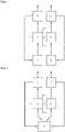
- the present invention proposes, in one embodiment, a method for the alkaline electrolysis of water with an electrolyte in an electrolyzer which has at least one electrolytic cell, a cathodic gas separator, an anodic gas separator, a first liquid reservoir for the electrolyte and a second liquid reservoir for the electrolyte, separate from the first liquid reservoir, the electrolytic cell comprising an anode half-cell with an anode, a cathode half-cell with a cathode, and a separator arranged between the anode half-cell and the cathode half-cell, with a current being applied to the electrolyzer filled with the electrolyte in order to To carry out electrolysis, with electrolyte being fed from the first liquid reservoir to the anode half-cell and the anolyte running out of the anode half-cell being fed to the anodic gas separator, in which the gas from the A nolyten is separated, and with electrolyte being fed
- the separator mentioned above is preferably a diaphragm, in particular a semi-permeable diaphragm.
- Zirconium oxide/polysulfonic acid membranes for example, can be specified as suitable diaphragm materials.
- suitable diaphragm material are oxide ceramic materials, as in the EP 0 126 490 A1 are described.
- the separator can also be a membrane, in particular a cation exchange membrane.
- a membrane in particular a cation exchange membrane.
- Such membranes can be based on sulphonated polymers and in particular on perfluorinated sulphonated polymers and are available, for example, under the trade name Nafion from DuPont.
- Particularly suitable cation exchange membranes are non-reinforced single layer sulfonated membranes commonly used for fuel cell applications.
- the electrolyte used in the process according to the invention is preferably an aqueous alkali metal hydroxide solution and particularly preferably an aqueous sodium hydroxide or potassium hydroxide solution.
- concentration of these bases is suitably in the range from 8 to 45% by weight and particularly preferably in the range from 20 to 40% by weight.
- the present invention is not subject to any significant restrictions and it is apparent to the person skilled in the art that the flow rate is also based on the size of the cathode and anode half-cell.
- the flow rate should be so high that no significant concentration difference between the electrolytes in the cathode and anode half-cell can develop during the electrolysis reaction, but on the other hand, high flow rates are associated with higher energy expenditure in relation to the pump power, so that a very high flow rate affects the efficiency of the process.
- a range of 1 to 6 L electrolyte /h*L half- cell volume and in particular 2 to 4 L electrolyte /h*L half- cell volume have proven to be particularly suitable flow rates in relation to the cell volume for the electrolyte.
- the temperature during the implementation of the electrolysis process is particularly suitable in a range from 50 to 95° C., a range from 65 to 92° C. is preferred and a range from 70 to 90° C. is particularly preferred.
- the method according to the invention can be advantageously further developed in that the electrolysis is carried out at a pressure which is higher than atmospheric pressure.
- the electrolysis can be carried out at a pressure in the range from 1 to 30 bar and in particular from 5 to 20 bar.
- a higher pressure has the advantage that the gases generated during the electrolysis process remain dissolved in the electrolyte, while at normal pressure they can be released as gas bubbles that increase the resistance of the electrolyte solution.
- a higher pressure also leads to higher systemic demands on the material, so that for cost reasons it can make sense to carry out the process at a pressure of not more than 1 bar, preferably not more than 500 mbar and particularly preferably not more than 250 bar above atmospheric pressure.
- the electrolysis is carried out at a current density in the range of up to 25 kA/m 2 and up to 15 kA/m 2 .
- a current density in the range of up to 25 kA/m 2 and up to 15 kA/m 2 .
- the efficiency of the process decreases.
- Current densities of more than 25 kA/m 2 generally place such high demands on the material that they are unfavorable from an economic point of view.
- electrolyzers which have a first liquid reservoir for the electrolyte and a second liquid reservoir for the electrolyte which is separate from the first liquid reservoir and into which the electrolyte from the cathodic and anodic gas separator is introduced. While the method expediently provides for the use of separate liquid reservoirs, these are not necessary if the electrolyte is introduced from the respective gas separator into the respective other half-cell (ie from the cathodic gas separator into the anode half-cell and vice versa) without a detour via a liquid reservoir.
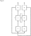
- a further aspect of the present invention therefore relates to a method for the alkaline electrolysis of water with an electrolyte in an electrolyzer which has at least one electrolytic cell, a cathodic gas separator and an anodic gas separator, the electrolytic cell having an anode half-cell with an anode, a cathode half-cell with a cathode, and a separator arranged between the anode half-cell and the cathode half-cell, with a current being applied to the electrolyzer filled with the electrolyte in order to carry out the electrolysis, with electrolyte being supplied from the cathodic gas separator exclusively to the anode half-cell and the anolyte running out of the anode half-cell being fed to the anodic Gas separator is supplied, in which the gas is separated from the anolyte, and wherein electrolyte is supplied from the anodic gas separator exclusively to the cathode half-cell and the catholyte running out of
- Another aspect of the present invention relates to a device for the electrolytic splitting of water into hydrogen and oxygen, which comprises an anode half-cell with an anode, a cathode half-cell with a cathode and a separator arranged between the anode half-cell and the cathode half-cell, the anode half-cell and the cathode half-cell each being in flow connection with a liquid reservoir separate from the anode half-cell and the cathode half-cell, respectively, and wherein the anode half-cell and the cathode half-cell are each in fluid communication with a gas separator separate from the anode half-cell and the cathode half-cell, respectively.
- the anode half-cell gas separator is in fluid communication with the cathode half-cell liquid reservoir and not in fluid communication with the anode half-cell liquid reservoir, while the cathode half-cell gas separator is in fluid communication with the anode half-cell first liquid reservoir and not in flow communication with the cathode half-cell first liquid reservoir.
- the latter distinguishes the device from a device for carrying out a divided circles process, since here the respective gas separators are in flow connection with a common one
- the electrolyte is expediently fed into the respective half-cells of the cell with the aid of suitable feed and discharge devices. This can be done with the help of a pump, for example.
- the device according to the invention is expediently made of a material, particularly in the area of the electrolytic cell, that is not attacked by the electrolyte, or is attacked only to a very small extent.
- a material is e.g. nickel, but also PPS and, depending on the lye concentration in the electrolyte, also nickel-alloyed stainless steel.
- the device according to the invention is also advantageously designed when the anode consists of a material containing nickel.
- Suitable nickel-containing material are, for example, Ni/Al or Ni/Co/Fe alloys or nickel coated with metal oxides such as perovskite or spinel type.
- metal oxides are lanthanum perovskites and cobalt spinels.
- a particularly suitable anode material is Ni/Al coated with Co 3 O 4 . Only the component in the electrolysis that is in direct contact with the electrolyte liquid is referred to as the anode.
- the cathode consists of a nickel-containing material.
- Nickel-containing materials suitable for the cathode are Ni-Co-Zn, Ni-Mo or Ni/Al/Mo alloys or Raney nickel (Ni/Al).
- the cathode can also be made from Raney nickel where some or most of the aluminum has been extracted to create a porous surface.
- a cathode can be used which essentially consists of nickel (ie at least 80% by weight, preferably at least 90% by weight) and which has a coating of Pt/C (platinum on carbon).
- the anode and/or the cathode is present as a wire mesh electrode or in the form of expanded metal or stamped sheet metal, it being preferred if at least the anode is present in such a form.
- the anode can also be provided with a catalytic coating. If a cation exchange membrane is used as the separator, the anode is suitably positioned in direct contact with the membrane.
- the anode can also be in contact with the wall of the anode half-cell via a current collector, which current collector can consist of a porous metal structure such as nickel or steel foam or wire mesh.
- a current collector can consist of a porous metal structure such as nickel or steel foam or wire mesh.
- the cathode can also be in contact with the wall of the cathode half-cell via a current collector, which can likewise consist of a porous metal structure, such as a nickel or steel foam or wire mesh.
- liquid reservoirs which are connected upstream of the anode and cathode half-cell in the direction of flow. These liquid reservoirs can be dispensed with as long as it is ensured that the electrolyte draining from the cathodic gas separator is fed exclusively to the anode half-cell and the electrolyte draining from the anodic gas separator is fed exclusively to the cathode half-cell.
- the present invention therefore also relates to a device for the electrolytic splitting of water into hydrogen and oxygen, which comprises an anode half-cell with an anode, a cathode half-cell with a cathode and a separator arranged between the anode half-cell and the cathode half-cell, the anode half-cell and the cathode half-cell are each in fluid communication with a separate gas separator with respect to the anode half-cell and the cathode half-cell, respectively.
- the gas separator of the anode half-cell is in fluid communication with the cathode half-cell and not in fluid communication with the anode half-cell, while the gas separator of the Cathode half cell is in fluid communication with the anode half cell and not in fluid communication with the cathode half cell.
- the device according to the invention preferably has a feed line for water in the electrolyte circuit.
- the water can be added at any point in the electrolyte circuit, e.g. in the area of the liquid reservoirs of the cathode and/or anode half-cell, the gas separator of the cathode and/or anode half-cell and/or the cathode and/or anode half-cell, or in lines, which combine these components of the device according to the invention.
- the water is preferably not added in the cathode and/or anode half-cell, since there is a risk of an inhomogeneous electrolyte concentration forming there, which can impair the efficiency of the process.
- an electrolyser can be obtained in which there can be an arrangement of several cells electrically connected in series.
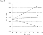
- An electrolytic device in which the electrolyte is passed through the cathode and anode half-cells of the electrolytic cell in separate cycles, was compared with a corresponding process according to the present invention.
- the respective electrolysis devices were filled with electrolytes of different NaOH concentrations.
- a cell having a surface area of 120 cm 2 was used as the electrolytic cell.
- the electrolysis was carried out at temperatures of 80° C. in each case.
Landscapes
- Chemical & Material Sciences (AREA)
- Engineering & Computer Science (AREA)
- Chemical Kinetics & Catalysis (AREA)
- Electrochemistry (AREA)
- Materials Engineering (AREA)
- Metallurgy (AREA)
- Organic Chemistry (AREA)
- Inorganic Chemistry (AREA)
- Life Sciences & Earth Sciences (AREA)
- Sustainable Development (AREA)
- Electrolytic Production Of Non-Metals, Compounds, Apparatuses Therefor (AREA)
- Electrodes For Compound Or Non-Metal Manufacture (AREA)
Applications Claiming Priority (2)
| Application Number | Priority Date | Filing Date | Title |
|---|---|---|---|
| DE102019123858.7A DE102019123858A1 (de) | 2019-09-05 | 2019-09-05 | Kreuzflusswasserelektrolyse |
| PCT/EP2020/073215 WO2021043578A1 (de) | 2019-09-05 | 2020-08-19 | Kreuzflusswasserelektrolyse |
Publications (2)
| Publication Number | Publication Date |
|---|---|
| EP4004259A1 EP4004259A1 (de) | 2022-06-01 |
| EP4004259B1 true EP4004259B1 (de) | 2022-10-19 |
Family
ID=72148140
Family Applications (1)
| Application Number | Title | Priority Date | Filing Date |
|---|---|---|---|
| EP20758201.6A Active EP4004259B1 (de) | 2019-09-05 | 2020-08-19 | Kreuzflusswasserelektrolyse |
Country Status (16)
| Country | Link |
|---|---|
| US (1) | US20220290319A1 (pt) |
| EP (1) | EP4004259B1 (pt) |
| JP (1) | JP7284344B6 (pt) |
| KR (1) | KR20220057576A (pt) |
| CN (1) | CN114402095B (pt) |
| AU (1) | AU2020342253B2 (pt) |
| BR (1) | BR112022003979A2 (pt) |
| CA (1) | CA3149042C (pt) |
| CL (1) | CL2022000504A1 (pt) |
| DE (1) | DE102019123858A1 (pt) |
| DK (1) | DK4004259T3 (pt) |
| ES (1) | ES2932629T3 (pt) |
| MA (1) | MA58224B1 (pt) |
| PT (1) | PT4004259T (pt) |
| WO (1) | WO2021043578A1 (pt) |
| ZA (1) | ZA202202236B (pt) |
Families Citing this family (2)
| Publication number | Priority date | Publication date | Assignee | Title |
|---|---|---|---|---|
| AT525914B1 (de) * | 2022-08-19 | 2023-09-15 | H2i GreenHydrogen GmbH | Elektrolysevorrichtung mit Naturumlauf |
| DE102022130401A1 (de) | 2022-11-17 | 2024-05-23 | WEW GmbH | Verfahren zur Erzeugung von Wasserstoff |
Citations (5)
| Publication number | Priority date | Publication date | Assignee | Title |
|---|---|---|---|---|
| DE102016202840A1 (de) | 2016-02-24 | 2017-08-24 | Siemens Aktiengesellschaft | Verfahren und Vorrichtung zur elektrochemischen Nutzung von Kohlenstoffdioxid |
| EP3339479A1 (en) | 2015-08-20 | 2018-06-27 | De Nora Permelec Ltd | Electrolysis apparatus and electrolysis method |
| EP3317435B1 (de) | 2015-07-03 | 2019-07-03 | Siemens Aktiengesellschaft | Reduktionsverfahren und elektrolysesystem zur elektrochemischen kohlenstoffdioxid-verwertung |
| WO2019229019A2 (de) | 2018-05-30 | 2019-12-05 | Thyssenkrupp Uhde Chlorine Engineers Gmbh | Verfahren und vorrichtung zum bereitstellen von wenigstens einem produktstrom durch elektrolyse sowie verwendung |
| EP3604617A1 (en) | 2017-03-23 | 2020-02-05 | Asahi Kasei Kabushiki Kaisha | Water electrolysis system, water electrolysis method and method for producing hydrogen |
Family Cites Families (13)
| Publication number | Priority date | Publication date | Assignee | Title |
|---|---|---|---|---|
| DE3318758C2 (de) | 1983-05-24 | 1985-06-13 | Kernforschungsanlage Jülich GmbH, 5170 Jülich | Diaphragma auf Nickeloxidbasis und Verfahren zur Herstellung desselben |
| DE19805058A1 (de) * | 1998-02-10 | 1999-08-19 | Mtu Friedrichshafen Gmbh | Verfahren und Einrichtung zum Unterdrücken von Potentialabfall beim Abschalten von bipolar geschalteten Wasserelektrolyseuren mit nicht getrennten Elektrolytkreisläufen |
| DE10342148A1 (de) * | 2003-09-12 | 2005-04-07 | Bayer Materialscience Ag | Verfahren zur Elektrolyse einer wässrigen Lösung von Chlorwasserstoff oder Alkalichlorid |
| TW201504477A (zh) * | 2013-07-17 | 2015-02-01 | Industrie De Nora Spa | 電解電池和鹼溶液電解槽以及在電池內之電解方法 |
| JP5897512B2 (ja) * | 2013-07-31 | 2016-03-30 | デノラ・ペルメレック株式会社 | 重水の電解濃縮方法 |
| US10190232B2 (en) * | 2013-08-06 | 2019-01-29 | Lam Research Corporation | Apparatuses and methods for maintaining pH in nickel electroplating baths |
| EP3237281B1 (de) * | 2014-12-22 | 2019-05-08 | AMEO Sports GmbH | Atemhilfe für schwimmer |
| CA3080528C (en) * | 2015-09-30 | 2022-06-21 | Kabushiki Kaisha Toshiba | Hydrogen production apparatus and hydrogen production system |
| WO2017081776A1 (ja) | 2015-11-11 | 2017-05-18 | 株式会社 東芝 | 水素製造装置、水素製造システム及び水素製造装置の製造方法 |
| JP6734920B2 (ja) | 2017-02-15 | 2020-08-05 | 旭化成株式会社 | 陰極、その製造方法、およびそれを用いた電解槽、水素製造方法 |
| DE102017216710A1 (de) * | 2017-09-21 | 2019-03-21 | Siemens Aktiengesellschaft | Elektrolyseuranordnung |
| JP2019090087A (ja) * | 2017-11-15 | 2019-06-13 | 株式会社東芝 | 電解槽及び水素製造装置 |
| CN107904617B (zh) * | 2017-11-23 | 2019-04-23 | 浙江大学 | 在硫碘循环制氢中以电化学分解hi制氢的方法及装置 |
-
2019
- 2019-09-05 DE DE102019123858.7A patent/DE102019123858A1/de active Pending
-
2020
- 2020-08-19 JP JP2022514587A patent/JP7284344B6/ja active Active
- 2020-08-19 EP EP20758201.6A patent/EP4004259B1/de active Active
- 2020-08-19 CA CA3149042A patent/CA3149042C/en active Active
- 2020-08-19 ES ES20758201T patent/ES2932629T3/es active Active
- 2020-08-19 AU AU2020342253A patent/AU2020342253B2/en active Active
- 2020-08-19 DK DK20758201.6T patent/DK4004259T3/da active
- 2020-08-19 KR KR1020227011024A patent/KR20220057576A/ko not_active Application Discontinuation
- 2020-08-19 US US17/639,779 patent/US20220290319A1/en active Pending
- 2020-08-19 BR BR112022003979A patent/BR112022003979A2/pt unknown
- 2020-08-19 MA MA58224A patent/MA58224B1/fr unknown
- 2020-08-19 WO PCT/EP2020/073215 patent/WO2021043578A1/de active Application Filing
- 2020-08-19 PT PT207582016T patent/PT4004259T/pt unknown
- 2020-08-19 CN CN202080062137.3A patent/CN114402095B/zh active Active
-
2022
- 2022-02-22 ZA ZA2022/02236A patent/ZA202202236B/en unknown
- 2022-03-01 CL CL2022000504A patent/CL2022000504A1/es unknown
Patent Citations (5)
| Publication number | Priority date | Publication date | Assignee | Title |
|---|---|---|---|---|
| EP3317435B1 (de) | 2015-07-03 | 2019-07-03 | Siemens Aktiengesellschaft | Reduktionsverfahren und elektrolysesystem zur elektrochemischen kohlenstoffdioxid-verwertung |
| EP3339479A1 (en) | 2015-08-20 | 2018-06-27 | De Nora Permelec Ltd | Electrolysis apparatus and electrolysis method |
| DE102016202840A1 (de) | 2016-02-24 | 2017-08-24 | Siemens Aktiengesellschaft | Verfahren und Vorrichtung zur elektrochemischen Nutzung von Kohlenstoffdioxid |
| EP3604617A1 (en) | 2017-03-23 | 2020-02-05 | Asahi Kasei Kabushiki Kaisha | Water electrolysis system, water electrolysis method and method for producing hydrogen |
| WO2019229019A2 (de) | 2018-05-30 | 2019-12-05 | Thyssenkrupp Uhde Chlorine Engineers Gmbh | Verfahren und vorrichtung zum bereitstellen von wenigstens einem produktstrom durch elektrolyse sowie verwendung |
Non-Patent Citations (2)
| Title |
|---|
| HAUG PHILIPP; KOJ MATTHIAS; TUREK THOMAS: "Influence of process conditions on gas purity in alkaline water electrolysis", INTERNATIONAL JOURNAL OF HYDROGEN ENERGY, vol. 42, no. 15, 12 January 2017 (2017-01-12), AMSTERDAM, NL, pages 9406 - 9418, XP085008072, ISSN: 0360-3199, DOI: 10.1016/j.ijhydene.2016.12.111 |
| RAHMAN FARAH ABD: "Design Optimization of a 2-Phase Gas/Liquid Separator", DISSERTATION, 1 January 2009 (2009-01-01), pages 1 - 74, XP093105018 |
Also Published As
| Publication number | Publication date |
|---|---|
| JP7284344B6 (ja) | 2024-02-19 |
| ES2932629T3 (es) | 2023-01-23 |
| CA3149042A1 (en) | 2021-03-11 |
| EP4004259A1 (de) | 2022-06-01 |
| CA3149042C (en) | 2024-01-02 |
| PT4004259T (pt) | 2022-12-09 |
| WO2021043578A1 (de) | 2021-03-11 |
| US20220290319A1 (en) | 2022-09-15 |
| JP7284344B2 (ja) | 2023-05-30 |
| ZA202202236B (en) | 2023-06-28 |
| AU2020342253A1 (en) | 2022-03-31 |
| JP2022548526A (ja) | 2022-11-21 |
| CL2022000504A1 (es) | 2022-09-23 |
| KR20220057576A (ko) | 2022-05-09 |
| CN114402095B (zh) | 2024-03-15 |
| MA58224B1 (fr) | 2022-11-30 |
| DE102019123858A1 (de) | 2021-03-11 |
| DK4004259T3 (da) | 2022-12-05 |
| BR112022003979A2 (pt) | 2022-05-24 |
| CN114402095A (zh) | 2022-04-26 |
| AU2020342253B2 (en) | 2023-02-09 |
Similar Documents
| Publication | Publication Date | Title |
|---|---|---|
| DE3018231A1 (de) | Verfahren zum herstellen von halogenen, verfahren zum erzeugen von chlor und aetzalkali sowie elektrolytische zelle | |
| EP4004259B1 (de) | Kreuzflusswasserelektrolyse | |
| EP1327011B1 (de) | Verfahren zur elektrochemischen herstellung von wasserstoffperoxid | |
| EP3084040B1 (de) | Vorrichtung und verfahren zum flexiblen einsatz von strom | |
| DE102017212278A1 (de) | CO2-Elektrolyseur | |
| DE4438275B4 (de) | Elektrolysezelle und Verfahren zur Elektrolyse einer wässrigen Kochsalzlösung | |
| DE1667369A1 (de) | Elektrolysezelle | |
| EP4136276B1 (de) | Elektrolysezelle, verfahren zum betrieb einer solchen zelle und elektrolyseur | |
| WO2015074637A1 (de) | Elektrochemische elektrolysezelle sowie verfahren zum betreiben derselben | |
| WO2019158307A1 (de) | Elektrochemische herstellung eines gases umfassend co mit zwischenkühlung des elektrolytstroms | |
| EP2886681A1 (de) | Elektrochemische Elektrolysezelle für die Wasserelektrolyse sowie Verfahren zum Betreiben derselben | |
| WO2018103769A1 (de) | Elektrolysezelle sowie verfahren zum betreiben einer solchen | |
| EP3159433B1 (de) | Elektrode für die alkalische wasserelektrolyse | |
| EP0234256B1 (de) | Verfahren zur Durchführung der HCI-Membranelektrolyse | |
| EP0865516B1 (de) | Elektrolytzelle | |
| DE2631523A1 (de) | Verfahren zur elektrolyse waessriger alkalihalogenidloesungen | |
| EP4127269B1 (de) | Verfahren und vorrichtung zur synthese von ammoniak | |
| EP0588149B1 (de) | Verfahren zur elektrochemischen Spaltung von Alkalisulfaten und Ammoniumsulfat in die freien Laugen und Schwefelsäure bei gleichzeitiger anodischer Oxidation von Schwefeldioxid | |
| DE102022210346A1 (de) | Metall-/kohlenstoffdioxid-batterie und wasserstoffproduktions- und kohlenstoffdioxid-speichersystem mit dieser batterie | |
| DE102022123619A1 (de) | Elektrolytisches Verfahren und Anlage | |
| EP4283017A1 (de) | Verfahren und anlage zur durchführung eines stoffumwandelnden verfahrens unter verwendung einer hochtemperaturzelle | |
| DE112021004643T5 (de) | Vorrichtung zur elektrolytischen Erzeugung von Wasserstoff | |
| DE102013009555B4 (de) | Verfahren zum Betreiben einer Niedertemperatur- Brennstoffzelle sowie Vorrichtung zur Durchführung des Verfahrens | |
| DE2745542A1 (de) | Verfahren zur elektrolyse von salzloesungen durch quecksilberkathoden | |
| DE102018009198A1 (de) | Verfahren zum Wechsel der Betriebsweise einer Elektrolyseanlage sowie Elektrolyseanlage |
Legal Events
| Date | Code | Title | Description |
|---|---|---|---|
| STAA | Information on the status of an ep patent application or granted ep patent |
Free format text: STATUS: UNKNOWN |
|
| STAA | Information on the status of an ep patent application or granted ep patent |
Free format text: STATUS: THE INTERNATIONAL PUBLICATION HAS BEEN MADE |
|
| PUAI | Public reference made under article 153(3) epc to a published international application that has entered the european phase |
Free format text: ORIGINAL CODE: 0009012 |
|
| STAA | Information on the status of an ep patent application or granted ep patent |
Free format text: STATUS: REQUEST FOR EXAMINATION WAS MADE |
|
| GRAP | Despatch of communication of intention to grant a patent |
Free format text: ORIGINAL CODE: EPIDOSNIGR1 |
|
| STAA | Information on the status of an ep patent application or granted ep patent |
Free format text: STATUS: GRANT OF PATENT IS INTENDED |
|
| 17P | Request for examination filed |
Effective date: 20220225 |
|
| AK | Designated contracting states |
Kind code of ref document: A1 Designated state(s): AL AT BE BG CH CY CZ DE DK EE ES FI FR GB GR HR HU IE IS IT LI LT LU LV MC MK MT NL NO PL PT RO RS SE SI SK SM TR |
|
| INTG | Intention to grant announced |
Effective date: 20220519 |
|
| RAV | Requested validation state of the european patent: fee paid |
Extension state: MA Effective date: 20220510 |
|
| GRAS | Grant fee paid |
Free format text: ORIGINAL CODE: EPIDOSNIGR3 |
|
| GRAA | (expected) grant |
Free format text: ORIGINAL CODE: 0009210 |
|
| STAA | Information on the status of an ep patent application or granted ep patent |
Free format text: STATUS: THE PATENT HAS BEEN GRANTED |
|
| AK | Designated contracting states |
Kind code of ref document: B1 Designated state(s): AL AT BE BG CH CY CZ DE DK EE ES FI FR GB GR HR HU IE IS IT LI LT LU LV MC MK MT NL NO PL PT RO RS SE SI SK SM TR |
|
| DAX | Request for extension of the european patent (deleted) | ||
| RAV | Requested validation state of the european patent: fee paid |
Extension state: MA Effective date: 20220510 |
|
| REG | Reference to a national code |
Ref country code: GB Ref legal event code: FG4D Free format text: NOT ENGLISH |
|
| REG | Reference to a national code |
Ref country code: CH Ref legal event code: EP |
|
| REG | Reference to a national code |
Ref country code: IE Ref legal event code: FG4D Free format text: LANGUAGE OF EP DOCUMENT: GERMAN |
|
| REG | Reference to a national code |
Ref country code: DE Ref legal event code: R096 Ref document number: 502020001870 Country of ref document: DE |
|
| REG | Reference to a national code |
Ref country code: AT Ref legal event code: REF Ref document number: 1525591 Country of ref document: AT Kind code of ref document: T Effective date: 20221115 |
|
| REG | Reference to a national code |
Ref country code: MA Ref legal event code: VAGR Ref document number: 58224 Country of ref document: MA Kind code of ref document: B1 |
|
| REG | Reference to a national code |
Ref country code: DK Ref legal event code: T3 Effective date: 20221128 |
|
| REG | Reference to a national code |
Ref country code: SE Ref legal event code: TRGR |
|
| REG | Reference to a national code |
Ref country code: PT Ref legal event code: SC4A Ref document number: 4004259 Country of ref document: PT Date of ref document: 20221209 Kind code of ref document: T Free format text: AVAILABILITY OF NATIONAL TRANSLATION Effective date: 20221202 |
|
| REG | Reference to a national code |
Ref country code: NL Ref legal event code: FP |
|
| REG | Reference to a national code |
Ref country code: NO Ref legal event code: T2 Effective date: 20221019 |
|
| REG | Reference to a national code |
Ref country code: ES Ref legal event code: FG2A Ref document number: 2932629 Country of ref document: ES Kind code of ref document: T3 Effective date: 20230123 |
|
| REG | Reference to a national code |
Ref country code: LT Ref legal event code: MG9D |
|
| PG25 | Lapsed in a contracting state [announced via postgrant information from national office to epo] |
Ref country code: LT Free format text: LAPSE BECAUSE OF FAILURE TO SUBMIT A TRANSLATION OF THE DESCRIPTION OR TO PAY THE FEE WITHIN THE PRESCRIBED TIME-LIMIT Effective date: 20221019 Ref country code: FI Free format text: LAPSE BECAUSE OF FAILURE TO SUBMIT A TRANSLATION OF THE DESCRIPTION OR TO PAY THE FEE WITHIN THE PRESCRIBED TIME-LIMIT Effective date: 20221019 |
|
| PG25 | Lapsed in a contracting state [announced via postgrant information from national office to epo] |
Ref country code: RS Free format text: LAPSE BECAUSE OF FAILURE TO SUBMIT A TRANSLATION OF THE DESCRIPTION OR TO PAY THE FEE WITHIN THE PRESCRIBED TIME-LIMIT Effective date: 20221019 Ref country code: PL Free format text: LAPSE BECAUSE OF FAILURE TO SUBMIT A TRANSLATION OF THE DESCRIPTION OR TO PAY THE FEE WITHIN THE PRESCRIBED TIME-LIMIT Effective date: 20221019 Ref country code: LV Free format text: LAPSE BECAUSE OF FAILURE TO SUBMIT A TRANSLATION OF THE DESCRIPTION OR TO PAY THE FEE WITHIN THE PRESCRIBED TIME-LIMIT Effective date: 20221019 Ref country code: IS Free format text: LAPSE BECAUSE OF FAILURE TO SUBMIT A TRANSLATION OF THE DESCRIPTION OR TO PAY THE FEE WITHIN THE PRESCRIBED TIME-LIMIT Effective date: 20230219 Ref country code: HR Free format text: LAPSE BECAUSE OF FAILURE TO SUBMIT A TRANSLATION OF THE DESCRIPTION OR TO PAY THE FEE WITHIN THE PRESCRIBED TIME-LIMIT Effective date: 20221019 Ref country code: GR Free format text: LAPSE BECAUSE OF FAILURE TO SUBMIT A TRANSLATION OF THE DESCRIPTION OR TO PAY THE FEE WITHIN THE PRESCRIBED TIME-LIMIT Effective date: 20230120 |
|
| P01 | Opt-out of the competence of the unified patent court (upc) registered |
Effective date: 20230530 |
|
| REG | Reference to a national code |
Ref country code: DE Ref legal event code: R026 Ref document number: 502020001870 Country of ref document: DE |
|
| PLBI | Opposition filed |
Free format text: ORIGINAL CODE: 0009260 |
|
| PG25 | Lapsed in a contracting state [announced via postgrant information from national office to epo] |
Ref country code: SM Free format text: LAPSE BECAUSE OF FAILURE TO SUBMIT A TRANSLATION OF THE DESCRIPTION OR TO PAY THE FEE WITHIN THE PRESCRIBED TIME-LIMIT Effective date: 20221019 Ref country code: RO Free format text: LAPSE BECAUSE OF FAILURE TO SUBMIT A TRANSLATION OF THE DESCRIPTION OR TO PAY THE FEE WITHIN THE PRESCRIBED TIME-LIMIT Effective date: 20221019 Ref country code: EE Free format text: LAPSE BECAUSE OF FAILURE TO SUBMIT A TRANSLATION OF THE DESCRIPTION OR TO PAY THE FEE WITHIN THE PRESCRIBED TIME-LIMIT Effective date: 20221019 Ref country code: CZ Free format text: LAPSE BECAUSE OF FAILURE TO SUBMIT A TRANSLATION OF THE DESCRIPTION OR TO PAY THE FEE WITHIN THE PRESCRIBED TIME-LIMIT Effective date: 20221019 |
|
| PLAX | Notice of opposition and request to file observation + time limit sent |
Free format text: ORIGINAL CODE: EPIDOSNOBS2 |
|
| 26 | Opposition filed |
Opponent name: SUNFIRE GMBH Effective date: 20230714 |
|
| PG25 | Lapsed in a contracting state [announced via postgrant information from national office to epo] |
Ref country code: SK Free format text: LAPSE BECAUSE OF FAILURE TO SUBMIT A TRANSLATION OF THE DESCRIPTION OR TO PAY THE FEE WITHIN THE PRESCRIBED TIME-LIMIT Effective date: 20221019 Ref country code: AL Free format text: LAPSE BECAUSE OF FAILURE TO SUBMIT A TRANSLATION OF THE DESCRIPTION OR TO PAY THE FEE WITHIN THE PRESCRIBED TIME-LIMIT Effective date: 20221019 |
|
| PGFP | Annual fee paid to national office [announced via postgrant information from national office to epo] |
Ref country code: NL Payment date: 20230821 Year of fee payment: 4 |
|
| PGFP | Annual fee paid to national office [announced via postgrant information from national office to epo] |
Ref country code: IT Payment date: 20230831 Year of fee payment: 4 Ref country code: NO Payment date: 20230824 Year of fee payment: 4 |
|
| PLAF | Information modified related to communication of a notice of opposition and request to file observations + time limit |
Free format text: ORIGINAL CODE: EPIDOSCOBS2 |
|
| PG25 | Lapsed in a contracting state [announced via postgrant information from national office to epo] |
Ref country code: SI Free format text: LAPSE BECAUSE OF FAILURE TO SUBMIT A TRANSLATION OF THE DESCRIPTION OR TO PAY THE FEE WITHIN THE PRESCRIBED TIME-LIMIT Effective date: 20221019 |
|
| PGFP | Annual fee paid to national office [announced via postgrant information from national office to epo] |
Ref country code: SE Payment date: 20230821 Year of fee payment: 4 Ref country code: PT Payment date: 20230810 Year of fee payment: 4 Ref country code: FR Payment date: 20230828 Year of fee payment: 4 Ref country code: DK Payment date: 20230823 Year of fee payment: 4 Ref country code: DE Payment date: 20230821 Year of fee payment: 4 Ref country code: BE Payment date: 20230821 Year of fee payment: 4 |
|
| PGFP | Annual fee paid to national office [announced via postgrant information from national office to epo] |
Ref country code: ES Payment date: 20231027 Year of fee payment: 4 |
|
| PLBB | Reply of patent proprietor to notice(s) of opposition received |
Free format text: ORIGINAL CODE: EPIDOSNOBS3 |
|
| PG25 | Lapsed in a contracting state [announced via postgrant information from national office to epo] |
Ref country code: MC Free format text: LAPSE BECAUSE OF FAILURE TO SUBMIT A TRANSLATION OF THE DESCRIPTION OR TO PAY THE FEE WITHIN THE PRESCRIBED TIME-LIMIT Effective date: 20221019 |
|
| REG | Reference to a national code |
Ref country code: CH Ref legal event code: PL |
|
| PG25 | Lapsed in a contracting state [announced via postgrant information from national office to epo] |
Ref country code: MC Free format text: LAPSE BECAUSE OF FAILURE TO SUBMIT A TRANSLATION OF THE DESCRIPTION OR TO PAY THE FEE WITHIN THE PRESCRIBED TIME-LIMIT Effective date: 20221019 |
|
| PG25 | Lapsed in a contracting state [announced via postgrant information from national office to epo] |
Ref country code: LU Free format text: LAPSE BECAUSE OF NON-PAYMENT OF DUE FEES Effective date: 20230819 |
|
| PG25 | Lapsed in a contracting state [announced via postgrant information from national office to epo] |
Ref country code: LU Free format text: LAPSE BECAUSE OF NON-PAYMENT OF DUE FEES Effective date: 20230819 Ref country code: CH Free format text: LAPSE BECAUSE OF NON-PAYMENT OF DUE FEES Effective date: 20230831 |
|
| REG | Reference to a national code |
Ref country code: IE Ref legal event code: MM4A |