WO2017081776A1 - 水素製造装置、水素製造システム及び水素製造装置の製造方法 - Google Patents
水素製造装置、水素製造システム及び水素製造装置の製造方法 Download PDFInfo
- Publication number
- WO2017081776A1 WO2017081776A1 PCT/JP2015/081783 JP2015081783W WO2017081776A1 WO 2017081776 A1 WO2017081776 A1 WO 2017081776A1 JP 2015081783 W JP2015081783 W JP 2015081783W WO 2017081776 A1 WO2017081776 A1 WO 2017081776A1
- Authority
- WO
- WIPO (PCT)
- Prior art keywords
- gas
- hydrogen
- container
- hydrogen production
- production apparatus
- Prior art date
Links
Images


Classifications
-
- C—CHEMISTRY; METALLURGY
- C25—ELECTROLYTIC OR ELECTROPHORETIC PROCESSES; APPARATUS THEREFOR
- C25B—ELECTROLYTIC OR ELECTROPHORETIC PROCESSES FOR THE PRODUCTION OF COMPOUNDS OR NON-METALS; APPARATUS THEREFOR
- C25B9/00—Cells or assemblies of cells; Constructional parts of cells; Assemblies of constructional parts, e.g. electrode-diaphragm assemblies; Process-related cell features
Definitions
- Embodiments relate to a hydrogen production apparatus, a hydrogen production system, and a method for producing a hydrogen production apparatus.
- hydrogen has attracted attention as a fuel with a low environmental impact. Since hydrogen itself has combustion energy, it can be used as a fuel in a narrow sense, but it can also be used as a medium for electric power energy when combined with a fuel cell. That is, electric power can be stored in the form of hydrogen by converting electric power to hydrogen by electrolysis of water and converting hydrogen to electric power by a fuel cell. This facilitates power storage and eliminates the need to match the time of power generation with the time of consumption. This increases the energy efficiency of society as a whole and makes it easy to prepare a standby power supply in the event of a disaster.
- An object of the embodiment is to provide a hydrogen production apparatus, a hydrogen production system, and a method for producing a hydrogen production apparatus that can reduce costs related to hydrogen production.
- the hydrogen production apparatus includes a lower container, an upper container disposed on the lower container, an electrolytic cell disposed in the upper container and electrolyzing an alkaline aqueous solution, and disposed in the upper container.
- An anode gas gas-liquid separation chamber that separates the oxygen gas generated on the anode side of the electrolytic cell and the alkaline aqueous solution; and the hydrogen gas generated on the cathode side of the electrolytic cell and the alkaline solution disposed in the upper container
- a pump for transporting the alkaline aqueous solution from the electrolytic solution tank to the electrolytic cell.
- the manufacturing method of the hydrogen production apparatus includes a lower container assembly process in which an electrolyte tank and a pump connected to the electrolyte tank are installed in the lower container, and an alkaline aqueous solution is electrically charged in the upper container.
- An electrolytic cell for decomposition, an anode gas gas-liquid separation chamber for separating oxygen gas generated on the anode side of the electrolytic cell and the alkaline aqueous solution, and hydrogen gas generated on the cathode side of the electrolytic cell and the alkaline aqueous solution An upper container assembly process for installing a cathode gas gas-liquid separation chamber to be separated; a loading process for placing the upper container on the lower container; and a lower part of the anode gas gas-liquid separation chamber is connected to the electrolyte tank. And a first connection step of connecting the lower part of the cathode gas gas-liquid separation chamber to the electrolyte tank, and a second connection step of connecting the pump to the electrolytic cell.
- FIG. 1 is a perspective view showing a hydrogen production system according to a first embodiment. It is a perspective view which shows the hydrogen production apparatus which concerns on 1st Embodiment, and shows the state which the lower container and the upper container isolate
- FIG. 1 It is a flowchart figure which shows the manufacturing method of the hydrogen production apparatus which concerns on 1st Embodiment.
- (A) And (b) is a schematic diagram which shows the flow of the alkaline aqueous solution in a hydrogen production apparatus, (a) shows 1st Embodiment, (b) shows a comparative example. It is a perspective view which shows the hydrogen production system which concerns on 2nd Embodiment. It is a system block diagram which shows the hydrogen production apparatus which concerns on 2nd Embodiment.
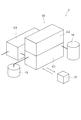
- FIG. 1 is a perspective view showing a hydrogen production system according to the present embodiment.
- the hydrogen production system according to the present embodiment is a system for producing hydrogen gas by electrolyzing water by an alkaline electrolysis method.
- a hydrogen production apparatus 20 is provided.
- Each device of the hydrogen production apparatus 20 is accommodated in three containers. That is, the hydrogen production apparatus 20 is provided with a lower container C1, an upper container C2, and a power supply container C3.
- the shapes and dimensions of the lower container C1 and the upper container C2 are equal to each other, for example, a standardized container, for example, a 12-foot container or a 20-foot container.
- An upper container C2 is placed on the lower container C1.
- the power supply container C3 is also a standardized container, for example, a 12-foot container or a 20-foot container.
- the power supply container C3 is disposed at a position slightly away from the vertically stacked structure composed of the lower container C1 and the upper container C2.
- a multi-core cable with a connector is connected between the lower container C1 and the power supply container C3.
- the hydrogen production system 1 is provided with a drain tank 15 for storing the waste liquid discharged from the hydrogen production apparatus 20.
- the drain tank 15 can be removed and replaced, and the removed drain tank can be transported to a disposal area by a truck or the like (not shown). Details of the waste liquid discarded in the drain tank 15 will be described later.
- the waste liquid discharged from the hydrogen production apparatus 20 is not stored in the drain tank 15, but can be directly drained to a drainage facility or the like outside the hydrogen production system 1 if possible. Has been.
- the hydrogen production system 1 is provided with a hydrogen tank 16 for storing hydrogen gas produced by the hydrogen production apparatus 20.
- the hydrogen gas stored in the hydrogen tank 16 is transported to a consumption place or another storage facility by a hydrogen truck or a pipeline (not shown).
- FIG. 2 is a perspective view showing the hydrogen production apparatus according to this embodiment, and shows a state where the lower container and the upper container are separated.
- FIG. 3 is a perspective view showing the hydrogen production apparatus according to the present embodiment, and shows a state where the lower container and the upper container are combined.
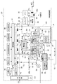
- FIG. 4 is a system configuration diagram showing the hydrogen production apparatus according to the present embodiment.
- the power supply container C3 is not shown. Moreover, in FIG.2 and FIG.3, only the comparatively large component is shown, The illustration of the small component and piping is abbreviate
- current and signal flows are indicated by broken lines, gas flows are indicated by alternate long and short dash lines, and liquid flows are indicated by solid lines.
- the components drawn in the dashed frame labeled C2 indicate the contents of the upper container C2, and the components drawn in the dashed frame labeled C3.
- the element indicates the contents of the power supply container C3, and the components drawn in the other areas indicate the contents of the lower container C1.
- a rectifier 21 is provided in the hydrogen production apparatus 20 according to the present embodiment.
- the rectifier 21 is housed in a power supply container C3 (see FIG. 1). In FIG. 4, this is expressed by drawing a block indicating the rectifier 21 within a broken line frame denoted by reference numeral C ⁇ b> 3.
- the rectifier 21 converts AC power P1 supplied from the outside, for example, AC power supplied from a commercial power system, into DC power P2 and AC power P3 and outputs it.
- an electrolytic cell 22 In the hydrogen production apparatus 20, an electrolytic cell 22, a cathode gas gas / liquid separation chamber 23, an anode gas gas / liquid separation chamber 24, and an electrolyte circulation tank 25 are provided.
- the electrolytic cell 22, the cathode gas gas-liquid separation chamber 23, and the anode gas gas-liquid separation chamber 24 are accommodated in the upper container C2.
- this is expressed by the fact that blocks indicating these components are drawn in a broken line frame denoted by reference symbol C ⁇ b> 2.
- the electrolyte circulation tank 25 is accommodated in the lower container C1. In FIG.
- the electrolytic bath 22 holds an alkaline aqueous solution S that is an electrolytic solution.
- an aqueous solution in which an electrolyte that facilitates electrolysis of water as a solvent is dissolved for example, an aqueous potassium hydroxide solution (KOH) or an aqueous sodium hydroxide solution (NaOH) can be used.
- the electrolytic cell 22 holds a potassium hydroxide aqueous solution (KOH) having a concentration of 25% by mass.
- the alkaline aqueous solution S is electrolyzed to generate hydrogen gas (H 2 ) and oxygen gas (O 2 ).
- the inside of the electrolytic cell 22 is partitioned into a plurality of cells by a diaphragm (not shown).
- the diaphragm is a film that allows water to pass therethrough but hardly allows gas to pass through.
- a polymer film made of PET PolyEthylene Terephthalate
- PET PolyEthylene Terephthalate
- anode electrode is disposed and is opposed to each other through a diaphragm.
- the electrolytic cell 22 is hermetically sealed, and one end of a hydrogen pipe 51 is connected to the ceiling part of the cell where the cathode electrode is arranged, and the oxygen pipe 52 is connected to the ceiling part of the cell where the anode electrode is arranged. One end is connected.
- the other end of the hydrogen pipe 51 is connected to the cathode gas gas-liquid separation chamber 23.
- the hydrogen gas and the alkaline aqueous solution S flow into the cathode gas gas-liquid separation chamber 23 from the electrolytic cell 22 through the hydrogen pipe 51 in a mixed state.
- the hydrogen gas and the alkaline aqueous solution S are separated in the cathode gas gas-liquid separation chamber 23. That is, the alkaline aqueous solution S falls to the lower part of the cathode gas gas-liquid separation chamber 23, and the hydrogen gas collects at the upper part of the cathode gas gas-liquid separation chamber 23.
- the other end of the oxygen pipe 52 is connected to the anode gas gas-liquid separation chamber 24.
- the oxygen gas and the alkaline aqueous solution S flow into the anode gas gas-liquid separation chamber 24 from the electrolytic cell 22 through the oxygen pipe 52 in a mixed state.
- the oxygen gas and the alkaline aqueous solution S are separated in the anode gas gas-liquid separation chamber 24. That is, the alkaline aqueous solution S falls to the lower part of the anode gas gas-liquid separation chamber 24, and the oxygen gas collects at the upper part of the anode gas gas-liquid separation chamber 24.
- an electrolyte tube 53 is connected to the lower portion, for example, the bottom surface, of the cathode gas-liquid separation chamber 23.
- the other end of the electrolytic solution pipe 53 is connected to an upper portion of the electrolytic solution circulation tank 25, for example, a ceiling portion.
- the electrolytic solution pipe 53 is provided from the upper container C2 to the lower container C1, and passes through the boundary between the upper container C2 and the lower container C1 (hereinafter referred to as “container boundary”) in the middle portion.
- a joint structure J1 is provided at a portion of the electrolyte pipe 53 that passes through the container boundary. Detailed configurations of the electrolyte pipe 53 and the joint structure J1 will be described later.
- an electrolyte tube 54 is connected to the lower portion, for example, the bottom surface, of the anode gas gas-liquid separation chamber 24.
- the other end of the electrolytic solution pipe 54 is connected to the upper portion of the electrolytic solution circulation tank 25, for example, a ceiling portion.
- the electrolyte pipe 54 is provided from the upper container C2 to the lower container C1, and passes through the container boundary at the intermediate portion.
- a joint structure J2 is provided at a portion of the electrolyte pipe 54 that passes through the container boundary. Detailed configurations of the electrolyte pipe 54 and the joint structure J2 will be described later.
- the cathode gas gas-liquid separation chamber 23 and the anode gas gas-liquid separation chamber 24 are arranged above the electrolyte circulation tank 25, the cathode gas gas-liquid separation chamber 23 and the anode gas gas-liquid separation chamber 24 are arranged.
- the alkaline aqueous solution S circulates by gravity.
- the electrolyte circulation tank 25 holds the alkaline aqueous solution S.
- a water level gauge (not shown) is attached to the electrolyte circulation tank 25.
- An electrolyte pipe 55 is connected between the lower part of the electrolyte circulation tank 25 and the lower part of the electrolytic tank 22.
- the electrolyte pipe 55 is provided from the lower container C1 to the upper container C2, and a joint structure J3 is provided at a portion straddling the container boundary. Detailed configurations of the electrolyte pipe 55 and the joint structure J3 will be described later.
- a pump 26 is interposed in the electrolyte pipe 55. The pump 26 is accommodated in the lower container C1.
- the alkaline aqueous solution S that is not electrolyzed is supplied from the electrolytic solution circulation tank 25 to the electrolytic cell 22 through the electrolytic solution pipe 55. Therefore, when the pump 26 is operated, the alkaline aqueous solution S circulates through the path of (electrolyzer 22 ⁇ cathode gas gas / liquid separation chamber 23 or anode gas gas / liquid separation chamber 24 ⁇ electrolyte circulation tank 25 ⁇ electrolyzer 22). To do.
- an air pump 27 is provided in the lower container C1 of the hydrogen production apparatus 20, an air pump 27 is provided.
- the suction port of the air pump 27 is open to the atmosphere, and an air pipe 56 is connected between the exhaust port of the air pump 27 and the electrolyte circulation tank 25.
- One end of an air pipe 57 is connected to the upper part of the electrolyte circulation tank 25, for example, the ceiling part.
- the other end of the air pipe 57 is disposed outside the lower container C1.
- pure water W is produced from tap water, and a pure water production apparatus 28 for holding the pure water W is provided.
- the electric conductivity of the pure water W is, for example, 10 ⁇ S / cm (micro Siemens per centimeter) or less.
- the pure water production apparatus 28 is stored in the lower container C1.
- a pure water pipe 58 is connected between the pure water production apparatus 28 and the upper part of the electrolytic solution circulation tank 25, for example, a ceiling portion.
- a pump 29 is interposed in the pure water pipe 58. By operating the pump 29, pure water W is supplied from the pure water production device 28 to the electrolyte circulation tank 25 through the pure water pipe 58.
- the pure water production apparatus 28 is also connected to the drain tank 15.
- the waste water can be temporarily stored in the removable drain tank 15 without being drained directly to the outside of the hydrogen production system 1, and the waste water can be discarded. It is possible to dispose of wastewater under appropriate treatment, such as transporting to the area and then draining. In the present embodiment, if possible, wastewater such as concentrated water generated with the production of pure water W can be directly drained to a drainage facility or the like outside the hydrogen production system 1.
- a cleaning tower 31, a pump 32, and a buffer tank 33 are provided in the upper container C2 of the hydrogen production apparatus 20, a cleaning tower 31, a pump 32, and a buffer tank 33 are provided.
- a hydrogen pipe 61 is connected to the upper part of the cathode gas gas-liquid separation chamber 23, for example, between the ceiling portion and the cleaning tower 31.
- the cleaning tower 31 is separated by the cathode gas gas-liquid separation chamber 23 and sprays the cleaning liquid C on the hydrogen gas supplied by the hydrogen pipe 61 by a shower to remove the alkali component.
- the cleaning liquid C is pure water, for example.
- the pump 32 circulates the cleaning liquid C held in the cleaning tower 31.
- the cleaning tower 31 and the pump 32 constitute a closed loop path by a cleaning liquid pipe 62.
- the buffer tank 33 holds the cleaning liquid C and supplies the cleaning liquid C to the cleaning tower 31 as necessary.
- a cleaning liquid pipe 63 is connected between the cleaning tower 31 and the buffer tank 33.
- the cleaning tower 31 and the buffer tank 33 are each connected to the drain tank 15 via a cleaning liquid pipe. These washing liquid pipes are respectively drawn from the washing tower 31 and the buffer tank 33 in the upper container C2 into the lower container C1 through the joint structures J4 and J5, and then drawn out of the lower container C1.
- the drain tank 15 has been reached.
- a compressor 34, a chiller 35, and a hydrogen purifier 36 are further provided in the lower container C1 of the hydrogen production apparatus 20, a compressor 34, a chiller 35, and a hydrogen purifier 36 are further provided.
- the upper part of the cleaning tower 31, for example, the ceiling part, and the intake port of the compressor 34 are connected by a hydrogen pipe 64.
- the hydrogen pipe 64 passes through the container boundary via the joint structure J6.
- the compressor 34 compresses the hydrogen gas discharged from the cleaning tower 31 and supplied via the hydrogen pipe 64.
- the chiller 35 cools the compressor 34.
- a hydrogen pipe 65 is connected between the exhaust port of the compressor 34 and the intake port of the hydrogen purifier 36.
- the hydrogen purifier 36 purifies the hydrogen gas compressed by the compressor 34 and supplied through the hydrogen pipe 65.
- a filter (not shown) that removes impurities in hydrogen gas, for example, moisture by chemical adsorption, is provided.
- a hydrogen pipe 66 is connected to the exhaust port of the hydrogen purifier 36.
- the hydrogen pipe 66 is bifurcated into a hydrogen pipe 67 and a hydrogen pipe 68, respectively.
- the hydrogen pipe 67 is connected to the hydrogen tank 16 (see FIG. 1).
- the hydrogen pipe 67 is provided with a normally closed valve 67v.
- the normally closed valve is in a “closed” state when demagnetized, that is, when a predetermined voltage is not applied, and when energized, that is, when a predetermined voltage is applied, the electromagnet acts.
- the valve is in the “open” state.
- the other end of the hydrogen pipe 68 is opened outside the lower container C1 and serves as an exhaust port.
- the hydrogen pipe 68 is provided with a normally open valve 68v.
- a normally open valve is a valve that is in an “open” state when demagnetized and is in a “closed” state by the action of an electromagnet when energized.
- an oxygen tube 69 is connected to the upper portion of the anode gas gas-liquid separation chamber 23, for example, the ceiling portion.
- the oxygen pipe 69 is drawn down to the inside of the lower container C1 across the container boundary by the joint structure J7, and then drawn out to the outside of the lower container C1.
- the other end of the oxygen pipe 69 is opened outside the lower container C1 and serves as an exhaust port.
- a nitrogen gas cylinder 38 is provided in the lower container C1 of the hydrogen production apparatus 20.
- a high-pressure nitrogen gas is sealed in the nitrogen gas cylinder 38.
- An inert gas other than nitrogen gas may be enclosed.
- a nitrogen pipe 71 is connected to the nitrogen gas cylinder 38 via a regulator (not shown) that keeps the pressure of the outflow gas constant. The pressure of the regulator is set to 0.2 MPa (megapascal), for example.
- the nitrogen pipe 71 is branched into nitrogen pipes 72 to 75.
- the nitrogen pipe 71 is pulled up to the upper container C2 across the container boundary between the branch point with the nitrogen pipe 72 and the branch point with the nitrogen pipe 73.
- a joint structure J8 is provided at a portion corresponding to the container boundary in the nitrogen pipe 71.
- the nitrogen pipe 72 is connected to the pure water pipe 58.
- the nitrogen pipe 72 is provided with a normally open valve 72v.
- the nitrogen tube 73 is connected to the oxygen tube 52.
- the nitrogen pipe 73 is provided with a normally open valve 73v.
- the nitrogen pipe 74 is connected to the hydrogen pipe 51.
- the nitrogen pipe 74 is provided with a normally open valve 74v.
- the nitrogen pipe 75 is connected to the hydrogen pipe 64.
- the nitrogen pipe 75 is provided with a normally open valve 75v.
- the upper part of the electrolytic cell 22, the upper part of the cathode gas gas-liquid separation chamber 23, the hydrogen pipe 51, the oxygen pipe 52, the hydrogen pipe 61, the hydrogen pipe 64, and the hydrogen pipe 65 are bypassed to communicate with the outside of the hydrogen production apparatus 20.
- a tube (not shown) is connected.
- Each bypass pipe is provided with a normally open valve.
- the hydrogen production device 20 includes a control device 41 that controls the operation of the hydrogen production device 20, a storage battery 42 that supplies power to the control device 41 in the event of a power failure, a power supply sensor 43 that detects that power P1 is no longer supplied, hydrogen gas There are provided a hydrogen leak detector 44 for detecting the leakage of the gas, an earthquake detector 45 for detecting the earthquake, and a fire detector 46 for detecting the fire.
- the electrical connection between each apparatus in the hydrogen production apparatus 20 is implement
- the control device 41 is operated by the AC power P3 generated by the rectifier 21, and controls the operation of each part of the hydrogen production device 20. Specifically, switching whether to supply DC power P2 to the electrolytic cell 22, switching whether to supply AC power P3 to each of the pump 26, the air pump 27, the pump 29, and the pump 32, normally closed valve 67v, normal open valves 68v, 72v, 73v, 74v and 75v, and switching of energizing or demagnetizing each of the normal open valves provided in the bypass pipes.
- the power sensor 43 outputs a warning signal to the control device 41 when the supply of the AC power P1 is stopped.
- the hydrogen leak detector 44 is disposed, for example, in the vicinity of the compressor 34, and outputs a warning signal to the control device 41 when the leak of hydrogen gas is detected.
- the earthquake detector 45 detects when an earthquake having a predetermined seismic intensity or more has occurred, and outputs a warning signal to the control device 41.
- D7G-F122 manufactured by OMRON Corporation can be used.
- the fire detector 46 is installed at an appropriate position in a building (not shown) where the hydrogen production apparatus 20 is installed, and outputs a warning signal to the control device 41 when a fire is detected.
- the power supply sensor 43, the hydrogen leak detector 44, the earthquake detector 45, and the fire detector 46 may be supplied with power from the control device 41 as necessary.
- FIG. 5 is a partial perspective view showing a connecting portion between the lower container and the upper container in the hydrogen production apparatus according to the present embodiment.
- a positioning pin 81 extending upward is provided on the ceiling of the lower container C1.
- a positioning hole 82 is formed in the floor of the upper container.
- the diameter of the positioning hole 82 is slightly larger than the diameter of the positioning pin 81.
- the positional relationship between the positioning pin 81 and the positioning hole 82 is such that the positioning pin 81 fits into the positioning hole 82 when the upper container C2 is placed on the lower container C1.
- the positioning pins 81 and the positioning holes 82 are provided at the four corners of the ceiling of the lower container C1 and the four corners of the upper container C2.
- one or more, for example, two bolt holes 83 are formed in the vicinity of the positioning pins 81 on the ceiling of the lower container C1.
- a screw groove is formed on the inner surface of the bolt hole 83.
- a through hole 84 is formed at a position corresponding to the bolt hole 83 on the floor of the upper container C2.
- the positioning pin 81 may be detachable from the ceiling of the lower container C1. As a result, during transportation of the lower container C1, the positioning pin 81 is removed for convenience of transportation, and the positioning pin 81 is attached to the lower container C1 immediately before the upper container C2 is placed on the lower container C1. be able to. Further, a stopper (not shown) may be detachable from the positioning hole 82, the bolt hole 83, and the through hole 84. As a result, during transportation of the lower container C1 and the upper container C2, a stopper is attached to prevent intrusion of water, dust, etc. from the outside, and the stopper is plugged immediately before the upper container C2 is placed on the lower container C1. Can be removed. Furthermore, the positioning pin 81 may be provided so as to extend downward on the floor of the upper container C2, and the positioning hole 82 may be opened in the ceiling of the lower container C1.
- ⁇ Piping connection configuration> Next, the connection part of the piping between the lower container C1 and the upper container C2 is demonstrated. As shown in FIG. 4, a joint structure J ⁇ b> 1 is provided in an electrolyte pipe 53 that connects the cathode gas-liquid separation chamber 23 and the electrolyte circulation tank 25.
- the joint structure J1 and its peripheral part will be described.
- FIG. 6 is a perspective view showing the joint structure and its peripheral part in the present embodiment.
- an upper tube 87 (cathode side upper tube) connected to a lower portion of the cathode gas gas-liquid separation chamber 23, for example, a bottom surface, and an upper portion of the electrolyte tank 25, for example, a ceiling.
- a lower tube 88 (cathode side lower tube) is provided.
- a flange 87 a is provided at the lower end of the upper pipe 87, and a flange 88 a is provided at the upper end of the lower pipe 88.
- the upper pipe 87 and the flange 87a are arranged in the upper container C2, and the lower pipe 88 and the flange 88a are arranged in the lower container C1.
- the upper tube 87, the flange 87a, the lower tube 88, and the flange 88a are made of, for example, a metal material.
- each ceiling hole 91 and each floor hole 92 are formed at positions where they communicate with each other when the upper container C2 is placed on the lower container C1. That is, when the upper container C2 is placed on the lower container C1, the interior of the lower container C1 and the interior of the upper container C2 are communicated with each other via, for example, seven ceiling holes 91 and floor holes 92.
- a joint structure J1 is connected between the upper pipe 87 and the lower pipe 88 of the electrolyte pipe 53.
- a flexible pipe 89 having flanges at both ends can be used.
- the flexible tube 89 is made of, for example, stainless steel.
- the flexible pipe 89 is provided with a main body 89c, a flange 89a is provided at the upper end of the main body 89c, and a flange 89b is provided at the lower end of the main body 89c. Since the main body 89c has a spiral shape, it has a certain degree of flexibility and can be deformed within a certain range.
- a flexible pipe 89 for example, a flexible hose with SUS304 10K flange manufactured by Daido Special Industrial Co., Ltd. can be used.
- tube 87 is connected with the flange 89a provided in the upper end part of the flexible pipe 89 by bolting, for example.
- the flange 88a provided at the upper end portion of the lower pipe 88 is connected to the flange 89b provided at the lower end portion of the flexible pipe 89 by, for example, bolting.
- the flexible pipe 89 passes through the inside of the ceiling hole 91 and the floor hole 92 communicated with each other, and crosses the container boundary. That is, the central portion in the longitudinal direction of the main body 89 c of the flexible tube 89 is disposed inside the ceiling hole 91 and the floor hole 92 that are in communication with each other.
- the upper pipe 87 is connected to the lower pipe 88 via the joint structure J1 including the flexible pipe 89.
- connection portion with the cathode gas gas-liquid separation chamber 23 is located above the connection portion with the electrolyte tank 25. For this reason, the alkaline aqueous solution S that has flowed from the cathode gas-liquid separation chamber 23 into the electrolyte pipe 53 flows to the electrolyte tank 25 by gravity.
- the direction in which the electrolyte tube 53 extends is horizontal, diagonally downward, or vertically downward, and does not go upward.
- the joint structure J1 has been described as an example, but the same applies to the joint structures J2 and J3 through which the alkaline aqueous solution S flows and the joint structures J4 and J5 through which the cleaning liquid C flows.
- an electrolyte pipe 54 that connects the anode gas gas-liquid separation chamber 24 and the electrolyte circulation tank 25 is also connected to the lower part of the anode gas gas-liquid separation chamber 24 and is disposed in the upper container C2 ( An anode side upper pipe) and a lower pipe (anode side lower pipe) connected to the upper part of the electrolyte circulation tank 25 and disposed in the lower container C1 are provided.
- the upper pipe is a joint structure including a flexible pipe. It is connected to the lower pipe through the body J2.
- the joint structure J6 through which hydrogen gas flows, the joint structure J7 through which oxygen gas flows, and the joint structure J8 through which nitrogen gas flows are made of a flexible resin such as Teflon (registered trademark).
- a resin hose (not shown) is provided, and both ends thereof are connected to the upper pipe 87 and the lower pipe 88 via a bite joint (not shown).
- a bite joint for example, a joint made by Swagelok can be used.
- Each of the joint structures J1 to J8 passes through the ceiling hole 91 and the floor hole 92 that are in communication with each other.
- the device arranged in the lower container C1 and the device arranged in the upper container C2 are electrically connected by a multicore cable with a connector that passes through the ceiling hole 91 and the floor hole 92.
- the floor, side plates (not shown) and the ceiling of the lower container C1 and the floor, side plates (not shown) and the ceiling of the upper container C2 have appropriate holes as necessary. It may be formed.
- FIG. 7 is a flowchart showing the method for manufacturing the hydrogen production apparatus according to this embodiment.
- a method for producing a hydrogen production apparatus will be described with reference to FIGS.
- each device is mounted in each container in the factory.
- the order of steps S1 to S3 is arbitrary and may be executed simultaneously.
- step S1 an electrolyte circulation tank 25, a pump 26, an air pump 27, a pure water production device 28, a pump 29, a compressor 34, a chiller 35, a hydrogen purifier 36, a nitrogen gas cylinder 38, a control are provided in the lower container C1.
- the apparatus 41, the storage battery 42, the power supply sensor 43, the hydrogen leak detector 44, the earthquake detector 45, and the fire detector 46 are installed and fixed. And each apparatus is connected by piping and wiring.
- the bolt hole 83 (refer FIG. 5) and the ceiling hole 91 (refer FIG. 6) formed in the ceiling of the lower container C1 are sealed with a stopper (not shown).
- the positioning pin 81 is removed from the lower container C1 and stored in the lower container C1.
- a multicore cable with a connector for connecting the lower container C1 and the power supply container C3 is stored in the lower container C1 in a wound state.
- step S2 the electrolytic cell 22, the cathode gas gas-liquid separation chamber 23, the anode gas gas-liquid separation chamber 24, the cleaning tower 31, the pump 32, and the buffer tank 33 are installed and fixed in the upper container C2. . And each apparatus is connected by piping and wiring. Further, the positioning hole 82, the through hole 84 (see FIG. 5) and the floor hole 92 (see FIG. 6) formed on the floor of the upper container C2 are sealed with a stopper (not shown).
- step S3 the rectifier 21 is mounted and fixed in the power supply container C3.
- step S4 the lower container C1, the upper container C2, and the power supply container C3 are transported to the place where the hydrogen generation system 1 is installed. Since each container is sealed and standardized, it can be transported at low cost by land, sea, and air using the existing container transportation system.
- the lower container C1 is installed at the location where the hydrogen generation system 1 is installed. Since the lower container C1 is a sturdy container, it can be hung directly from the transportation site such as a truck, for example, using a crane. Thereafter, the stopper is removed from the ceiling of the lower container C1, and the bolt hole 83 (see FIG. 5) and the ceiling hole 91 (see FIG. 6) are opened. Further, a positioning pin 81 (see FIG. 5) is attached to the ceiling of the lower container C1.
- step S6 the stopper is removed from the floor of the upper container C2, and the positioning hole 82, the through hole 84 (see FIG. 5), and the floor hole 92 (see FIG. 6) are opened.
- the upper container C2 is lifted from a transport such as a truck using a crane, and the upper container C2 is gradually lowered from directly above the lower container C1.
- the positioning pin 81 of the lower container C1 is inserted into the positioning hole 82 of the upper container C2.
- the upper container C2 is further lowered, and the floor of the upper container C2 is brought into contact with the ceiling of the lower container C1.
- each through hole 84 formed in the floor of the upper container C2 communicates with each bolt hole 83 formed in the ceiling of the lower container C1.
- each floor hole 92 formed in the floor of the upper container C2 communicates with each ceiling hole 91 formed in the ceiling of the lower container C1.
- the upper tube 87 (cathode side upper tube) of the electrolyte tube 53 can be connected to the lower tube 88 (cathode side lower tube) of the electrolyte tube 53 via the floor hole 92 and the ceiling hole 91.
- the upper pipe 87 (anode-side upper pipe) of the electrolyte pipe 54 can also be connected to the lower pipe 88 (anode-side lower pipe) of the electrolyte pipe 54 through the other floor hole 92 and ceiling hole 91. .
- step S ⁇ b> 7 of FIGS. 5 and 7 the bolt 85 is inserted into the through hole 84 from above and screwed in the bolt hole 83. Thereby, the upper container C2 is connected to the lower container C1.
- Step S8 of FIGS. 6 and 7 the pipe provided in the lower container C1 and the pipe provided in the upper container C2 are connected by a joint structure.
- the joint structure J1 will be described as an example.
- the flexible pipe 89 is inserted into the ceiling hole 91 and the floor hole 92 that are communicated with each other.
- tube 89 is connected with the flange 87a provided in the lower end part of the upper pipe
- the flange 89b provided at the lower end portion of the flexible tube 89 is connected to the flange 88a provided at the upper end portion of the lower tube 88 by, for example, bolting.
- the upper pipe 87 and the lower pipe 88 of the electrolytic solution pipe 53 are connected via the joint structure J1.
- the flexible pipe 89 is flexible and can be deformed within a certain range, the upper pipe 87 and the lower pipe are arranged even if the flange 87a is arranged at a position slightly shifted from the region directly above the flange 88a. 88 can be securely connected.
- the joint structures J2 to J5 are connected in the same manner.
- a resin hose made of Teflon (registered trademark) or the like is inserted into the ceiling hole 91 and the floor hole 92 communicated with each other. And the upper end part of the resin hose is connected to the lower end part of the upper pipe 87 via a bite joint, and the lower end part of the resin hose is connected to the upper end part of the lower pipe 88 via a bite joint. Since the resin hose is also flexible, even if the position of the upper tube 87 is displaced from the region directly above the lower tube 88, the displacement can be absorbed. Moreover, the control apparatus 41 mounted in the lower container C1, the electrolytic cell 22 mounted in the upper container C2, and each pump are electrically connected by a multicore cable with a connector.
- the power supply container C3 is installed in the vicinity of the lower container C1 using a crane or the like.
- the rectifier 21 housed in the power supply container C3 is connected to the existing power system.
- a multicore cable with a connector housed in the lower container C ⁇ b> 1 is pulled out, and the rectifier 21 is connected to the electrolytic cell 22 and the control device 41. In this way, the hydrogen production apparatus 20 is produced.
- the power supply container C3 may be installed before the upper container C2, or may be installed before the lower container C1.
- a drain tank 15 and a hydrogen tank 16 are installed in the vicinity of the hydrogen production apparatus 20.
- each pipe of the hydrogen production apparatus 20 is connected to the drain tank 15, and the hydrogen pipe 67 is connected to the hydrogen tank 16.
- the pure water production apparatus 28 of the hydrogen production apparatus 20 is connected to a water source such as a water supply. In this way, the hydrogen production system 1 is produced.
- the drain tank 15 and the hydrogen tank 16 may be installed before the hydrogen production apparatus 20.
- the fire detector 46 may be taken out from the lower container C1 and attached to an arbitrary place of the building where the hydrogen production apparatus 20 is installed.
- AC power P ⁇ b> 1 is supplied from the existing power system to the rectifier 21 of the hydrogen production apparatus 20.
- the rectifier 21 converts AC power P1 into DC power P2 and AC power P3.
- the rectifier 21 outputs an alternating current P3 to the control device 41, the storage battery 42, the pumps 26, 29, and 32, the air pump 27, the pure water production device 28, and the compressor 34 of the hydrogen production device 20.
- the alkaline aqueous solution S is held in the electrolyte circulation tank 25 and the electrolytic tank 22.
- the alkaline aqueous solution S is, for example, a potassium hydroxide aqueous solution having a concentration of 25% by mass.
- the cleaning liquid C is held in the cleaning tower 31 and the buffer tank 33.
- control device 41 applies a predetermined voltage to the normally closed valve 67v and the normally open valves 68v, 72v, 73v, 74v and 75v to excite them.
- the normally closed valve 67v is opened and the hydrogen pipe 68 communicates.
- the normally open valves 68v, 72v, 73v, 74v and 75v are closed.
- the hydrogen purifier 36 is connected to the hydrogen tank 16 via the hydrogen pipes 66 and 67.
- the nitrogen gas cylinder 38 is not connected anywhere and is in a sealed state.
- the normally open valve provided in each bypass pipe is excited to be in a closed state. Thereby, each bypass pipe is sealed.
- the control device 41 operates the pure water production device 28.
- the pure water manufacturing apparatus 28 manufactures and holds the pure water W from, for example, tap water.
- the pure water production apparatus 28 discards the waste liquid generated in the process of producing the pure water W in the drain tank 15.
- the waste water can be temporarily stored in the removable drain tank 15 without being drained directly to the outside of the hydrogen production system 1, and the waste water can be discarded. Dispose of wastewater under appropriate treatment, such as transporting to the area and then draining.
- waste water such as concentrated water generated with the production of pure water W is directly drained to a drainage facility or the like outside the hydrogen production system 1.
- control device 41 operates the pump 26, the pump 32, the compressor 34, and the chiller 35.
- the pump 26 By operating the pump 26, the alkaline aqueous solution S held in the electrolytic solution circulation tank 25 is supplied into the electrolytic cell 22 through the electrolytic solution pipe 55.
- the cleaning liquid C circulates between the cleaning tower 31 and the pump 32, and the cleaning liquid C is injected into the gas phase in the upper part of the cleaning tower 31.
- the compressor 34 When the compressor 34 is operated, the gas flowing into the intake port of the compressor 34 is compressed and discharged from the exhaust port.
- the compressor 34 is cooled by operating the chiller 35.
- the control device 41 supplies DC power P2 from the rectifier 21 to the electrolytic cell 22.
- a current flows between the cathode electrode and the anode electrode of the electrolytic cell 22, water in the alkaline aqueous solution S is electrolyzed, hydrogen gas is generated on the cathode electrode side, and oxygen gas is generated on the anode electrode side. appear.
- the water in the alkaline aqueous solution S in the electrolytic cell 22 is consumed, hydrogen gas accumulates in the upper part of the cell including the cathode electrode, and oxygen gas accumulates in the upper part of the cell including the anode electrode.
- the alkaline aqueous solution S accumulated in the cathode gas gas-liquid separation chamber 23 returns to the electrolyte circulation tank 25 through the electrolyte tube 53. Further, the alkaline aqueous solution S accumulated in the anode gas gas-liquid separation chamber 24 returns to the electrolyte circulation tank 25 through the electrolyte pipe 54.
- the cathode gas gas-liquid separation chamber 23 and the anode gas gas-liquid separation chamber 24 are disposed in the upper container C2
- the electrolyte circulation tank 25 is disposed in the lower container C1
- the alkaline aqueous solution S is gravity-induced. To fall into the electrolyte circulation tank 25.
- the pump 29 is operated based on the output of the water level gauge attached to the electrolytic solution circulation tank 25, and pure water W is replenished to the electrolytic solution circulation tank 25 from the pure water production device 28 via the pure water pipe 58. .
- the concentration of the alkaline aqueous solution S is always maintained within a certain range.
- the pure water production apparatus 28 produces the pure water W when the retained amount of the pure water W decreases below a certain value, and stops producing the pure water W when the retained amount reaches a certain value.
- the oxygen gas separated by the anode gas gas-liquid separation chamber 24 is exhausted to the outside of the hydrogen production apparatus 20 through the oxygen pipe 69. Further, the hydrogen gas separated by the cathode gas gas-liquid separation chamber 23 is introduced into the cleaning tower 31 through the hydrogen pipe 61. The hydrogen gas introduced into the cleaning tower 31 is showered with the cleaning liquid C, and the remaining alkaline components are dissolved in the cleaning liquid C and removed. As a result, the purity of hydrogen gas is improved.
- the hydrogen gas from which alkali components have been removed in the cleaning tower 31 is sent to the compressor 34 via the hydrogen pipe 64, compressed to, for example, 0.8 MPa (megapascal) by the compressor 34, and sent to the hydrogen purifier 36. .
- the hydrogen purifier 36 impurities such as moisture are removed by passing hydrogen gas through the filter. Then, it is sent to the hydrogen tank 16 through the hydrogen pipes 66 and 67 and stored in the hydrogen tank 16.
- the hydrogen generation system 1 can produce hydrogen gas by supplying electric power and water from the outside.
- the hydrogen gas stored in the hydrogen tank 16 is sometimes filled in, for example, a hydrogen lorry vehicle and transported to a consumption place.
- the alkaline aqueous solution S deteriorates due to the electrolysis of water, it is discharged from the electrolyte circulation tank 25 to the drain tank 15. At this time, a new alkaline aqueous solution S is carried in by a truck or the like separately from the pure water W and replenished to the electrolyte circulation tank 25.
- the cleaning liquid C is contaminated by exceeding the predetermined standard by dissolving the alkali component, the cleaning liquid C is discharged from the buffer tank 33 to the drain tank 15. Then, a new cleaning liquid C is carried in by a truck or the like and is replenished to the buffer tank 33.
- the drain tank 15 in which the waste liquid is stored is appropriately removed from the hydrogen production system 1 and replaced with an empty drain tank 15.
- the drain tank 15 storing the waste liquid is transported to a disposable area by a truck or the like, where the waste liquid is discarded.
- the waste liquid can be transported to a disposable area and appropriately discarded. Thereby, it can contribute to environmental protection.
- the hydrogen gas path in the hydrogen production apparatus 20 that is, the hydrogen pipe 51, the cathode gas gas-liquid separation chamber 23, the hydrogen pipe 61, the cleaning tower 31, the hydrogen pipe 64, the compressor
- the hydrogen gas remains in the gas pipe 34, the hydrogen pipe 65, the hydrogen purifier 36, the hydrogen pipe 66, and the hydrogen pipe 67. Since hydrogen gas is explosive, there is a possibility of explosion due to, for example, static electricity. For this reason, it is dangerous to leave hydrogen gas in the stopped hydrogen production apparatus 20.
- the control apparatus 41 when the power sensor 43 detects that the AC power P1 is not supplied, a warning signal is output to the control apparatus 41.
- the control device 41 can be driven for a certain period by the electric power stored in the storage battery 42.
- the control device 41 When the control device 41 receives the warning signal from the power supply sensor 43, the control device 41 turns off each device of the hydrogen production device 20, that is, the electrolytic cell 22, the hydrogen production device 28, and each pump. Thereby, even if supply of electric power P1 is restarted later, the hydrogen production apparatus 20 will not be inadvertently restarted. Further, the control device 41 demagnetizes the normally closed valve 67v and the normally open valve 68v. As a result, the normally closed valve 67v is closed and the normally open valve 68v is opened, so that the path of the hydrogen pipe 66 is switched, the connection with the hydrogen tank 16 is cut off, and the outside communicates with the outside through the hydrogen pipe 68. Is done.
- control device 41 demagnetizes the normally open valves 72v, 73v, 74v, and 75v to open them.
- the nitrogen gas in the nitrogen gas cylinder 38 is supplied to each part of the hydrogen production apparatus 20 through the nitrogen pipes 71 to 75.
- the pressure of the nitrogen gas flowing out from the nitrogen gas cylinder 38 is maintained at, for example, 0.2 MPa or more by a regulator.
- the control apparatus 41 demagnetizes the normally open valve provided in each bypass pipe, and makes it an open state. Thereby, each hydrogen pipe is connected to the outside of the hydrogen production apparatus 20, that is, the outside of the lower container C1 and the upper container C2.
- nitrogen gas is introduced into the oxygen pipe 52 through the nitrogen pipes 71 and 73.
- the oxygen gas path of the hydrogen production apparatus 20, that is, the oxygen pipe 52, the anode gas gas-liquid separation chamber 24, and the oxygen pipe 69 is purged with nitrogen gas, and the oxygen gas remaining in the oxygen gas path is hydrogenated.
- the air is exhausted outside the manufacturing apparatus 20. As a result, it is possible to eliminate the danger caused by the remaining oxygen gas.
- nitrogen gas is introduced into the hydrogen pipe 51 via the nitrogen pipes 71 and 74.
- Nitrogen gas is introduced into the hydrogen pipe 64 through the nitrogen pipes 71 and 75.
- the inside of the hydrogen gas path of the hydrogen production apparatus 20 is purged with nitrogen gas, and the hydrogen gas remaining in the hydrogen gas path is exhausted to the outside of the hydrogen production apparatus 20 through the hydrogen pipe 68 and each bypass pipe. .
- the normally open valve 74v is a valve connected between the nitrogen gas cylinder 38 and the hydrogen pipe 51.
- the normally open valve 74v is excited and closed, and the AC power P1 is supplied. When it is not done, it is demagnetized and opened.
- the normally open valve 74v is opened, the hydrogen pipe 51 is purged with nitrogen gas.
- the normally open valve 75v is a valve connected between the nitrogen gas cylinder 38 and the hydrogen pipe 64.
- the normally open valve 75v is excited and closed, and the AC power P1 is not supplied. When opened, it is demagnetized and opened.
- the normally open valve 75v is opened, the inside of the hydrogen pipe 64 is purged with nitrogen gas.
- the “purging” in this case is sufficient if the hydrogen gas concentration in the hydrogen gas path is less than the explosion limit of 4%, and it is not necessary to replace all the hydrogen gas in the hydrogen gas path with nitrogen gas.
- each valve When the supply of power is stopped, each valve is demagnetized, the normal close valve 67v is automatically closed, and the normal open valves 68v, 72v, 73v, 74v and 75v, and the normal provided in each bypass pipe
- the open valve is automatically opened.
- the pressure of the nitrogen gas is applied by adjusting the pressure of the nitrogen gas itself enclosed in the nitrogen gas cylinder 38 by a regulator, and the pressure is applied to the hydrogen gas generated from the electrolytic cell 22.
- the pressure of pure water supplied to the electrolyte circulation tank 25 can push out pure water W and hydrogen gas from the respective pipes. For this reason, even if the control device 41 does not operate for some reason, the valves are appropriately switched to supply nitrogen gas, and the above-described purging with nitrogen gas becomes possible.
- a hydrogen leak detector 44 is provided in the hydrogen production system 1 according to the present embodiment.
- the control apparatus 41 stops the electrolytic cell 22, the pure water manufacturing apparatus 28, and each pump, and stops the electrolysis of water. Thereafter, by demagnetizing each valve, the inside of the pure water pipe 58, the hydrogen gas path, and the oxygen gas path are purged with nitrogen gas as in the case of the power failure described above.
- an earthquake detector 45 is provided.
- the control apparatus 41 stops the electrolysis tank 22, the pure water manufacturing apparatus 28, and each pump similarly to the case where the above-mentioned hydrogen gas leaks, and stops the electrolysis of water.
- the inside of the pure water pipe 58, the hydrogen gas path, and the oxygen gas path are purged with nitrogen gas.
- leakage of hydrogen gas can be prevented beforehand. If an earthquake occurs, the supply of AC power P1 may be stopped. Also in this case, as in the case of the power failure described above, the control device 41 is operated by the storage battery 42 or each valve is automatically demagnetized, so that the purge with nitrogen gas can be executed.
- ⁇ Fire> When a fire occurs in a building where the hydrogen generator 20 is installed, a flame may be applied to the hydrogen gas in the hydrogen production apparatus 20 to cause an explosion accident. Therefore, in the hydrogen production system 1 according to this embodiment, when a fire occurs, the fire detector 46 outputs a warning signal to the control device 41. And the control apparatus 41 takes the same treatment as the case where the above-mentioned hydrogen gas leaks. At this time, by exhausting the hydrogen gas and oxygen gas in the hydrogen production apparatus 20 to the outside, it is possible to prevent the hydrogen gas from igniting or the oxygen gas from promoting a fire.
- each valve If the power supply stops, each valve is demagnetized. For this reason, even when the control device 41 is destroyed due to an earthquake or a fire, each valve is automatically switched appropriately to supply nitrogen gas, and the above-described purging with nitrogen gas becomes possible.
- FIGS. 8A and 8B are schematic views showing the flow of the alkaline aqueous solution in the hydrogen production apparatus, FIG. 8A shows this embodiment, and FIG. 8B shows a comparative example.
- an electrolyte circulation tank 25 is provided in the lower container C1, and the cathode gas gas-liquid separation chamber 23 is provided in the upper container C2. And an anode gas gas-liquid separation chamber 24 is provided.
- the electrolyte pipe 53 is connected to the bottom surface of the cathode gas gas-liquid separation chamber 23 and the other end is connected to the ceiling portion of the electrolyte circulation tank 25, the electrolyte gas is separated from the cathode gas gas-liquid separation chamber 23.
- the path along the electrolyte pipe 53 toward the circulation tank 25 is down. Thereby, the alkaline aqueous solution S can be moved by gravity from the cathode gas-liquid separation chamber 23 toward the electrolyte circulation tank 25. Therefore, there is no need to provide a pump interposed in the electrolyte pipe 53.
- the alkaline aqueous solution S is supplied to the anode gas gas-liquid separation chamber. It can be moved by gravity from 24 toward the electrolyte circulation tank 25. Therefore, there is no need to provide a pump interposed in the electrolyte pipe 54.
- the cathode gas gas-liquid separation chamber 123, the anode gas gas-liquid separation chamber 124, and the electrolysis are provided in the same container C11.
- a liquid circulation tank 125 is provided on the same plane.
- the end 153a of the electrolyte pipe 153 is connected to the bottom surface of the cathode gas gas-liquid separation chamber 123 and the other end 153b is connected to the ceiling portion of the electrolyte circulation tank 125, the end 153a is connected to the end 153b. Therefore, a pump 153p for lifting the alkaline aqueous solution S from the end 153a to the end 153b is necessary.
- electrolyte pipe 154 connected between the bottom surface of the anode gas gas-liquid separation chamber 124 and the ceiling portion of the electrolyte circulation tank 125, for lifting the alkaline aqueous solution S from the end 154a to the end 154b.
- a pump 154p is required.
- the equipment cost of the hydrogen production apparatus 120 increases. Moreover, since the weight of the hydrogen production apparatus 120 increases, the transportation cost of the container C11 also increases. Furthermore, since the electric power for operating the pumps 153p and 154p is required, the operating cost of the hydrogen production apparatus 120 also increases. Thus, since the hydrogen production apparatus 120 according to the comparative example has high initial cost and operation cost, the production cost of hydrogen gas becomes high.
- the hydrogen production apparatus 20 according to the present embodiment does not need to be provided with pumps interposed in the electrolyte pipes 53 and 54, respectively, the equipment cost is low and the container transportation cost is low. In addition, since no electric power is required to operate these pumps, the operation cost is low. As a result, hydrogen gas can be produced at low cost.
- the level difference of the electrolyte pipe 55 is larger than that in the hydrogen production apparatus 120 according to the comparative example, and thus the output required for the pump 26 is high.
- both the equipment cost and the power are lower when one high-output pump 26 is provided than when three pumps 26, 153p and 154p are provided.
- the lower container C1 and the upper container C2 are vertically stacked, and the cathode gas gas-liquid separation chamber 23 and the anode gas gas-liquid separation chamber 24 are provided in the upper container C2.
- the electrolyte circulation tank 25 is disposed in the lower container C1. Thereby, the alkaline aqueous solution S can be conveyed by gravity from the cathode gas gas-liquid separation chamber 23 and the anode gas gas-liquid separation chamber 24 toward the electrolyte circulation tank 25.
- each device in a factory with a working environment, each device is incorporated in the lower container C1, the upper container C2, and the power container C3, and the lower container C1, the upper container C2, and the power container C3 are assembled.
- the manufacturing cost and transportation cost of the hydrogen production apparatus 20 it is possible to shorten the preparation period until the hydrogen production apparatus 20 is operated after the container is transported to the installation location of the hydrogen production apparatus 20. . Also by this, the cost of the hydrogen production apparatus 20 can be reduced.
- the installation area of the hydrogen production apparatus 20 can be reduced. Also by this, the cost of the hydrogen production apparatus 20 can be reduced.
- the positioning pin 81 is provided on the ceiling of the lower container C1, and the positioning hole 82 is formed on the floor of the upper container C2. For this reason, when the upper container C2 is placed on the lower container C1 by the crane, the upper container C2 can be easily positioned with respect to the lower container C1 by inserting the positioning pins 81 into the positioning holes 82. . Thereby, the upper container C2 can be installed in a short time, and the installation cost of the hydrogen generator 20 is reduced.
- each pipe in the lower container C1 and each pipe in the upper container C2 are connected by joint structures J1 to J8. .
- the piping connection work after container installation is simplified, and the installation cost of the hydrogen generator 20 is reduced.
- the hydrogen production device 20 is automatically stopped and the hydrogen gas remaining in the hydrogen production device 20 Can be discharged. Thereby, the explosion accident by the residual hydrogen gas can be prevented beforehand.
- water is electrolyzed using an alkaline aqueous solution.
- the electrical conductivity required for pure water is 10 ⁇ S / cm or less.
- the electrical conductivity required for pure water is 5 ⁇ S / cm or less (see Non-Patent Document 2).
- the alkaline electrolysis method requires a lower purity of pure water than the solid electrolyte membrane method.
- a solid electrolyte membrane containing platinum powder is necessary.
- the alkaline electrolysis method such expensive parts are unnecessary. For these reasons, the alkaline electrolysis system is less expensive than the solid electrolyte membrane system.
- FIG. 9 is a perspective view showing a hydrogen production system according to the present embodiment.
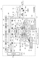
- FIG. 10 is a system configuration diagram showing the hydrogen production apparatus according to this embodiment.
- the hydrogen production system 2 according to this embodiment is provided in the hydrogen production apparatus 30 as compared with the hydrogen production system 1 (see FIG. 1) according to the first embodiment described above.
- a pure water tank 48 is provided instead of the pure water production apparatus 28 .
- the pure water tank 48 can hold the pure water W, but cannot manufacture it.
- a transport container 17 is provided outside the hydrogen production apparatus 30 so as to be transportable.
- pure water W required for the production of hydrogen is produced in a pure water production factory in another area, for example, an industrial area, filled in a transport container 17 and conveyed by a truck or the like (not shown), This is supplied to the pure water tank 48 of the hydrogen production apparatus 30.
- the transport container 17 is made of, for example, stainless steel, and has a substantially cubic shape. The length of one side is about 1 m, a manhole is attached to the upper surface, and a faucet is attached to the lower surface.
- a stainless steel container (sanitary cold protection specification) manufactured by Japan Logistics Equipment can be used.
- the transport container 17 is not limited to a stainless steel container, and may be a resin container made of polypropylene or the like, for example.
- the pure water W held in the pure water tank 48 is supplied to the electrolyte circulation tank 25 by a pump 29 as appropriate.
- the pure water W is supplied from the outside to the pure water tank 48 of the hydrogen production system 2 using the transport container 17. Thereby, even when pure water W cannot be produced inside the hydrogen production system 2, as in the case where raw water for producing pure water W cannot be supplied from water sources such as tap water, industrial water, rivers, and lakes. Hydrogen gas can be produced.
- the transport container 17 is made of stainless steel, impurities that reduce the purity of the pure water W, such as carbon dioxide gas and oxygen gas, permeate the wall of the transport container 17. It can suppress mixing in the pure water W. Moreover, the component which melt
- the present invention is not limited to this.
- the rectifier 21 is not necessary, and the power supply container C3 is unnecessary.
- the rectifier can be downsized and installed in the lower container C1 or the upper container C2, so that the power supply container C3 is also unnecessary.
- the hydrogen production apparatus may be divided into four or more containers and assembled.
- an uninterruptible power supply may be provided and connected to the path of the DC power P2.
- the uninterruptible power supply is a storage battery having a capacity larger than that of the storage battery 42, and can supply the DC power P2 to the electrolytic cell 22 for a certain period of time to continue the electrolysis. Thereby, if it is a power failure for a short time, a driving
Landscapes
- Chemical & Material Sciences (AREA)
- Engineering & Computer Science (AREA)
- Chemical Kinetics & Catalysis (AREA)
- Electrochemistry (AREA)
- Materials Engineering (AREA)
- Metallurgy (AREA)
- Organic Chemistry (AREA)
- Electrolytic Production Of Non-Metals, Compounds, Apparatuses Therefor (AREA)
Abstract
実施形態に係る水素製造装置は、下段コンテナと、前記下段コンテナ上に配置される上段コンテナと、前記上段コンテナ内に配置され、アルカリ性水溶液を電気分解する電解槽と、前記上段コンテナ内に配置され、前記電解槽の陽極側で発生した酸素ガスと前記アルカリ性水溶液とを分離する陽極ガス気液分離室と、前記上段コンテナ内に配置され、前記電解槽の陰極側で発生した水素ガスと前記アルカリ性水溶液とを分離する陰極ガス気液分離室と、前記下段コンテナ内に配置され、前記陽極ガス気液分離室の下部及び前記陰極ガス気液分離室の下部から前記アルカリ性水溶液が流入する電解液タンクと、前記電解液タンクから前記電解槽に前記アルカリ性水溶液を搬送するポンプと、を備える。
Description
実施形態は、水素製造装置、水素製造システム及び水素製造装置の製造方法に関する。
近年、環境負荷が小さい燃料として、水素が注目されている。水素は、それ自体が燃焼エネルギーを持つため、狭義の燃料として使うことも可能であるが、燃料電池と組み合わせることにより、電力エネルギーの媒体物として使うこともできる。すなわち、水の電気分解によって電力を水素に変換し、燃料電池によって水素を電力に変換することにより、電力を水素の形態で貯蔵することができる。これにより、電力の貯蔵が容易になり、発電時と消費時を一致させる必要がなくなるため、社会全体としてエネルギー効率が高まると共に、災害時の予備電源を用意しておくことも容易になる。
水素を用いたエネルギーシステムを普及させるためには、水素の製造に関係するコストを低減することが有効である。
「水電解法による水素製造とそのコスト」阿部勲夫、水素エネルギーシステム vol.33、No.1(2008)p.19-26
株式会社神鋼環境ソリューション ホームページ、http://www.kobelco-eco.co.jp/product/suisohassei/hhog_qa.html#Q1
実施形態の目的は、水素の製造に関係するコストを低減できる水素製造装置、水素製造システム及び水素製造装置の製造方法を提供することである。
実施形態に係る水素製造装置は、下段コンテナと、前記下段コンテナ上に配置される上段コンテナと、前記上段コンテナ内に配置され、アルカリ性水溶液を電気分解する電解槽と、前記上段コンテナ内に配置され、前記電解槽の陽極側で発生した酸素ガスと前記アルカリ性水溶液とを分離する陽極ガス気液分離室と、前記上段コンテナ内に配置され、前記電解槽の陰極側で発生した水素ガスと前記アルカリ性水溶液とを分離する陰極ガス気液分離室と、前記下段コンテナ内に配置され、前記陽極ガス気液分離室の下部及び前記陰極ガス気液分離室の下部から前記アルカリ性水溶液が流入する電解液タンクと、前記電解液タンクから前記電解槽に前記アルカリ性水溶液を搬送するポンプと、を備える。
実施形態に係る水素製造装置の製造方法は、下段コンテナ内に、電解液タンク、及び、前記電解液タンクに接続されたポンプを設置する下段コンテナ組立工程と、上段コンテナ内に、アルカリ性水溶液を電気分解する電解槽、前記電解槽の陽極側で発生した酸素ガスと前記アルカリ性水溶液とを分離する陽極ガス気液分離室、及び、前記電解槽の陰極側で発生した水素ガスと前記アルカリ性水溶液とを分離する陰極ガス気液分離室を設置する上段コンテナ組立工程と、前記下段コンテナ上に前記上段コンテナを載置する積載工程と、前記陽極ガス気液分離室の下部を前記電解液タンクに接続すると共に、前記陰極ガス気液分離室の下部を前記電解液タンクに接続する第1接続工程と、前記ポンプを前記電解槽に接続する第2接続工程と、を備える。
(第1の実施形態)
以下、図面を参照しつつ、本発明の実施形態について説明する。
先ず、第1の実施形態について説明する。
以下、図面を参照しつつ、本発明の実施形態について説明する。
先ず、第1の実施形態について説明する。
<水素製造システムの全体構成>
先ず、本実施形態に係る水素製造システム及びその周辺の構成について説明する。
図1は、本実施形態に係る水素製造システムを示す斜視図である。
本実施形態に係る水素製造システムは、アルカリ電解方式により水を電気分解することにより、水素ガスを製造するシステムである。
先ず、本実施形態に係る水素製造システム及びその周辺の構成について説明する。
図1は、本実施形態に係る水素製造システムを示す斜視図である。
本実施形態に係る水素製造システムは、アルカリ電解方式により水を電気分解することにより、水素ガスを製造するシステムである。
図1に示すように、本実施形態に係る水素製造システム1においては、水素製造装置20が設けられている。水素製造装置20の各機器は、3つのコンテナに収容されている。すなわち、水素製造装置20には、下段コンテナC1、上段コンテナC2及び電源用コンテナC3が設けられている。下段コンテナC1及び上段コンテナC2の形状及び寸法は相互に等しく、例えば、規格化されたコンテナであり、例えば、12フィートコンテナ又は20フィートコンテナである。下段コンテナC1上に、上段コンテナC2が載置されている。電源用コンテナC3も規格化されたコンテナであり、例えば、12フィートコンテナ又は20フィートコンテナである。
後述するように、下段コンテナC1の天井及び上段コンテナC2の床にはいくつかの穴が形成されており、これらの穴を介して、下段コンテナC1と上段コンテナC2との間には、複数本の配管が接続されている。また、下段コンテナC1とドレンタンク15との間、及び、下段コンテナC1と水素タンク16との間にも、それぞれ配管が接続されている。
また、電源用コンテナC3は、下段コンテナC1及び上段コンテナC2からなる縦積みの構造体から少し離れた位置に配置されている。下段コンテナC1と電源用コンテナC3との間には、コネクタ付き多芯ケーブルが接続されている。
また、水素製造システム1には、水素製造装置20から排出された廃液を貯蔵するドレンタンク15が設けられている。ドレンタンク15は、取り外して交換することができ、取り外したドレンタンクはトラック等(図示せず)により廃棄可能地域まで輸送することができる。ドレンタンク15に廃棄される廃液の詳細については、後述する。
水素製造システム1においては、水素製造装置20から排出された廃液をドレンタンク15に貯蔵せずに、可能な場合には直接、水素製造システム1の外部の排水設備等に排水できるようにも構成されている。
水素製造システム1においては、水素製造装置20から排出された廃液をドレンタンク15に貯蔵せずに、可能な場合には直接、水素製造システム1の外部の排水設備等に排水できるようにも構成されている。
更に、水素製造システム1には、水素製造装置20によって製造された水素ガスを貯蔵する水素タンク16が設けられている。水素タンク16に貯蔵された水素ガスは、水素ローリー車又はパイプライン等(図示せず)により、消費地又は他の貯蔵施設まで輸送される。
<水素製造装置の構成>
次に、本実施形態に係る水素製造装置の構成について説明する。
図2は、本実施形態に係る水素製造装置を示す斜視図であり、下段コンテナと上段コンテナが分離した状態を示す。
図3は、本実施形態に係る水素製造装置を示す斜視図であり、下段コンテナと上段コンテナが結合した状態を示す。
図4は、本実施形態に係る水素製造装置を示すシステム構成図である。
次に、本実施形態に係る水素製造装置の構成について説明する。
図2は、本実施形態に係る水素製造装置を示す斜視図であり、下段コンテナと上段コンテナが分離した状態を示す。
図3は、本実施形態に係る水素製造装置を示す斜視図であり、下段コンテナと上段コンテナが結合した状態を示す。
図4は、本実施形態に係る水素製造装置を示すシステム構成図である。
なお、図2及び図3においては、電源用コンテナC3は図示を省略している。また、図2及び図3においては、比較的大型の構成要素のみを示しており、小型の構成要素及び配管は、図示を省略している。更に、図2及び図3においては、各コンテナの側板及び天井は図示を省略している。
図4においては、図示の便宜上、電流及び信号の流れは破線で示し、気体の流れは一点鎖線で示し、液体の流れは実線で示している。また、図4に示す構成要素のうち、符号C2を付した破線の枠内に描かれた構成要素は上段コンテナC2の内容物を示し、符号C3を付した破線の枠内に描かれた構成要素は電源用コンテナC3の内容物を示し、それ以外の領域に描かれた構成要素は下段コンテナC1の内容物を示す。
図4においては、図示の便宜上、電流及び信号の流れは破線で示し、気体の流れは一点鎖線で示し、液体の流れは実線で示している。また、図4に示す構成要素のうち、符号C2を付した破線の枠内に描かれた構成要素は上段コンテナC2の内容物を示し、符号C3を付した破線の枠内に描かれた構成要素は電源用コンテナC3の内容物を示し、それ以外の領域に描かれた構成要素は下段コンテナC1の内容物を示す。
図4に示すように、本実施形態に係る水素製造装置20においては、整流器21が設けられている。整流器21は電源用コンテナC3(図1参照)内に収納されている。なお、これは、図4においては、符号C3を付した破線の枠内に整流器21を示すブロックが描かれていることによって表現されている。整流器21は、外部から供給された交流電力P1、例えば、商用の電力系統から供給された交流電力を、直流電力P2及び交流電力P3に変換して出力する。
水素製造装置20においては、電解槽22、陰極ガス気液分離室23、陽極ガス気液分離室24、及び、電解液循環タンク25が設けられている。このうち、電解槽22、陰極ガス気液分離室23及び陽極ガス気液分離室24は、上段コンテナC2内に収納されている。これは、図4においては、符号C2を付した破線の枠内にこれらの構成要素を示すブロックが描かれていることによって表現されている。一方、電解液循環タンク25は、下段コンテナC1内に収納されている。これは、図4においては、符号20を付した破線の枠内であって、符号C2を付した破線の枠外であって符号C3を付した破線の枠外に電解液循環タンク25を示すブロックが描かれていることによって表現されている。電解液循環タンク25は、ドレンタンク15に接続されている。
電解槽22は、電解液であるアルカリ性水溶液Sを保持する。アルカリ性水溶液Sとしては、溶媒である水の電気分解が容易になるような電解質が溶解した水溶液、例えば、水酸化カリウム水溶液(KOH)、又は、水酸化ナトリウム水溶液(NaOH)等を用いることができる。本実施形態においては、例えば、電解槽22は濃度が25質量%の水酸化カリウム水溶液(KOH)を保持している。そして、整流器21から直流電力P2が供給されると、アルカリ性水溶液Sを電気分解し、水素ガス(H2)及び酸素ガス(O2)を生成する。電解槽22の内部は、隔膜(図示せず)によって複数のセルに区画されている。隔膜は、水は通過させるが気体はほとんど通過させない膜であり、例えば、PET(PolyEthylene Terephthalate)からなる高分子フィルムにおいて、その両面又はいずれか一方の面に高分子不織布が貼り合わされた膜である。各セル内には、陰極電極(図示せず)又は陽極電極(図示せず)が配置されており、隔膜を介して対向している。電解槽22は密閉されており、陰極電極が配置されたセルの天井部分には、水素管51の一端が接続されており、陽極電極が配置されたセルの天井部分には、酸素管52の一端が接続されている。
陰極ガス気液分離室23には、水素管51の他端が接続されている。これにより、陰極ガス気液分離室23には、電解槽22から水素管51を介して水素ガス及びアルカリ性水溶液Sが混合した状態で流入する。水素ガスとアルカリ性水溶液Sは、陰極ガス気液分離室23内で分離される。すなわち、アルカリ性水溶液Sは陰極ガス気液分離室23の下部に落ち、水素ガスは陰極ガス気液分離室23の上部に集まる。
陽極ガス気液分離室24には、酸素管52の他端が接続されている。これにより、陽極ガス気液分離室24には、電解槽22から酸素管52を介して酸素ガス及びアルカリ性水溶液Sが混合した状態で流入する。酸素ガスとアルカリ性水溶液Sは、陽極ガス気液分離室24内で分離される。すなわち、アルカリ性水溶液Sは陽極ガス気液分離室24の下部に落ち、酸素ガスは陽極ガス気液分離室24の上部に集まる。
陰極ガス気液分離室23の下部、例えば底面には、電解液管53の一端が接続されている。電解液管53の他端は、電解液循環タンク25の上部、例えば天井部分に接続されている。このため、電解液管53は、上段コンテナC2から下段コンテナC1にわたって設けられており、中間部分で上段コンテナC2と下段コンテナC1との境界(以下、「コンテナ境界」という)を通過している。電解液管53におけるコンテナ境界を通過する部分には、継手構造体J1が設けられている。電解液管53及び継手構造体J1の詳細な構成は後述する。
一方、陽極ガス気液分離室24の下部、例えば底面には、電解液管54の一端が接続されている。電解液管54の他端は、電解液循環タンク25の上部、例えば天井部分に接続されている。このため、電解液管54は、上段コンテナC2から下段コンテナC1にわたって設けられており、中間部分でコンテナ境界を通過している。電解液管54におけるコンテナ境界を通過する部分には、継手構造体J2が設けられている。電解液管54及び継手構造体J2の詳細な構成は後述する。このように、陰極ガス気液分離室23及び陽極ガス気液分離室24は電解液循環タンク25よりも上方に配置されているため、陰極ガス気液分離室23及び陽極ガス気液分離室24から電解液循環タンク25に向けて、アルカリ性水溶液Sが重力によって流通する。
電解液循環タンク25はアルカリ性水溶液Sを保持している。電解液循環タンク25には水位計(図示せず)が取り付けられている。電解液循環タンク25の下部と電解槽22の下部との間には、電解液管55が接続されている。電解液管55は下段コンテナC1から上段コンテナC2にわたって設けられており、コンテナ境界を跨ぐ部分には、継手構造体J3が設けられている。電解液管55及び継手構造体J3の詳細な構成は後述する。電解液管55には、ポンプ26が介在している。ポンプ26は下段コンテナC1内に収納されている。
そして、ポンプ26が作動することにより、電解液循環タンク25から電解液管55を介して電解槽22に電解されていないアルカリ性水溶液Sが供給される。従って、ポンプ26が作動することにより、(電解槽22→陰極ガス気液分離室23又は陽極ガス気液分離室24→電解液循環タンク25→電解槽22)の経路で、アルカリ性水溶液Sが循環する。
水素製造装置20の下段コンテナC1内には、エアポンプ27が設けられている。エアポンプ27の吸入口は大気に開放されており、エアポンプ27の排気口と電解液循環タンク25との間には、空気管56が接続されている。また、電解液循環タンク25の上部、例えば天井部分には、空気管57の一端が接続されている。空気管57の他端は、下段コンテナC1の外部に配置されている。これにより、エアポンプ27が作動すると、電解液循環タンク25内の空気が下段コンテナC1外に排出され、新しい空気と入れ替わる。また、エアポンプ27が作動することにより、電解液循環タンク25内に保持されたアルカリ性水溶液Sを、一時的にドレンタンク15に排出することもできる。
水素製造装置20においては、例えば水道水から純水Wを製造し、この純水Wを保持する純水製造装置28が設けられている。純水Wの電気伝導度は、例えば、10μS/cm(マイクロジーメンス毎センチメートル)以下である。純水製造装置28は下段コンテナC1内に収納されている。純水製造装置28と電解液循環タンク25の上部、例えば、天井部分との間には、純水管58が接続されている。純水管58には、ポンプ29が介在している。ポンプ29が作動することにより、純水Wが純水製造装置28から純水管58を介して電解液循環タンク25に供給される。
純水製造装置28はドレンタンク15にも接続されている。本実施形態においては、環境保護等を考慮して、廃水を水素製造システム1の外部に直接排水せずに、取り外しが可能なドレンタンク15に一時的に貯蔵して、廃水を廃棄が可能な地域まで輸送してから排水する等、適切な処理のもとで廃水を廃棄することが可能である。また、本実施形態においては、可能な場合には、純水Wの製造に伴って発生した濃縮水等の廃水を、水素製造システム1の外部の排水設備等に直接排水することもできる。
水素製造装置20の上段コンテナC2内には、洗浄塔31、ポンプ32及びバッファタンク33が設けられている。陰極ガス気液分離室23の上部、例えば天井部分と洗浄塔31との間には、水素管61が接続されている。洗浄塔31は、陰極ガス気液分離室23によって分離され、水素管61によって供給された水素ガスに対して、洗浄液Cをシャワーにより吹きかけて、アルカリ成分を除去する。洗浄液Cは、例えば純水である。
また、ポンプ32は、洗浄塔31内に保持された洗浄液Cを循環させる。洗浄塔31及びポンプ32は、洗浄液管62によって閉じたループ経路を構成している。バッファタンク33は、洗浄液Cを保持し、必要に応じて洗浄液Cを洗浄塔31に供給する。洗浄塔31とバッファタンク33との間には、洗浄液管63が接続されている。洗浄塔31及びバッファタンク33は、それぞれ、洗浄液管を介してドレンタンク15に接続されている。これらの洗浄液管は、それぞれ、上段コンテナC2内の洗浄塔31及びバッファタンク33から継手構造体J4及びJ5を介して下段コンテナC1内まで引き下ろされた後、下段コンテナC1の外部に引き出され、ドレンタンク15に到達している。
水素製造装置20の下段コンテナC1内には、更に、コンプレッサ34、チラー35及び水素精製機36が設けられている。洗浄塔31の上部、例えば天井部分とコンプレッサ34の吸気口とは、水素管64により接続されている。水素管64は、継手構造体J6を介してコンテナ境界を通過している。コンプレッサ34は、洗浄塔31から排出され水素管64を介して供給された水素ガスを圧縮する。チラー35はコンプレッサ34を冷却する。コンプレッサ34の排気口と水素精製機36の吸気口との間には、水素管65が接続されている。水素精製機36は、コンプレッサ34により圧縮され水素管65を介して供給された水素ガスを精製する。水素精製機36内には、水素ガス中の不純物、例えば、水分を化学吸着させて取り除くフィルタ(図示せず)が設けられている。
水素精製機36の排気口には、水素管66の一端が接続されている。水素管66は二叉に分岐しており、それぞれ水素管67及び水素管68となっている。水素管67は水素タンク16(図1参照)に接続されている。水素管67には、ノーマルクローズバルブ67vが設けられている。ノーマルクローズバルブとは、消磁されているとき、すなわち、所定の電圧が印加されないときは、「閉」状態となり、励磁されたとき、すなわち、所定の電圧が印加されたときは、電磁石の作用により「開」状態となるバルブである。水素管68の他端は、下段コンテナC1の外部において開口しており、排気口となっている。水素管68には、ノーマルオープンバルブ68vが設けられている。ノーマルオープンバルブとは、消磁されているときは「開」状態となり、励磁されたときは電磁石の作用により「閉」状態となるバルブである。
一方、陽極ガス気液分離室23の上部、例えば天井部分には、酸素管69の一端が接続されている。酸素管69は継手構造体J7によりコンテナ境界を越えて下段コンテナC1内まで引き下ろされた後、下段コンテナC1の外部まで引き出されている。酸素管69の他端は下段コンテナC1の外部において開口しており、排気口となっている。
水素製造装置20の下段コンテナC1内には、窒素ガスボンベ38が設けられている。窒素ガスボンベ38内には、高圧の窒素ガスが封入されている。なお、窒素ガス以外の不活性ガスが封入されていてもよい。窒素ガスボンベ38には、流出ガスの圧力を一定にするレギュレータ(図示せず)を介して、窒素管71が接続されている。レギュレータの圧力は、例えば0.2MPa(メガパスカル)に設定されている。窒素管71は窒素管72~75に分岐している。窒素管71は窒素管72との分岐点と窒素管73との分岐点との間でコンテナ境界を越えて上段コンテナC2まで引き上げられている。窒素管71におけるコンテナ境界に相当する部分には、継手構造体J8が設けられている。
窒素管72は純水管58に接続されている。窒素管72には、ノーマルオープンバルブ72vが設けられている。窒素管73は酸素管52に接続されている。窒素管73には、ノーマルオープンバルブ73vが設けられている。窒素管74は水素管51に接続されている。窒素管74には、ノーマルオープンバルブ74vが設けられている。窒素管75は水素管64に接続されている。窒素管75には、ノーマルオープンバルブ75vが設けられている。また、電解槽22の上部、陰極ガス気液分離室23の上部、水素管51、酸素管52、水素管61、水素管64、水素管65には、水素製造装置20の外部に連通したバイパス管(図示せず)が接続されている。各バイパス管には、ノーマルオープンバルブが設けられている。
水素製造装置20には、水素製造装置20の動作を制御する制御装置41、停電時に制御装置41に電力を供給する蓄電池42、電力P1が供給されなくなったことを検知する電源センサ43、水素ガスの漏洩を検知する水素漏洩検知器44、地震を検知する地震検知器45、及び、火災を検知する火災検知器46が設けられている。なお、水素製造装置20における各機器間の電気的な接続は、例えば、コネクタ付き多芯ケーブル(図示せず)によって実現されている。
制御装置41は、整流器21が生成した交流電力P3によって作動し、水素製造装置20の各部の動作を制御する。具体的には、電解槽22に直流電力P2を供給するか否かのスイッチング、ポンプ26、エアポンプ27、ポンプ29及びポンプ32のそれぞれに交流電力P3を供給するか否かのスイッチング、ノーマルクローズバルブ67v、並びにノーマルオープンバルブ68v、72v、73v、74v及び75v、並びに、各バイパス管に設けられたノーマルオープンバルブのそれぞれを励磁するか消磁するかのスイッチング等を行う。
電源センサ43は、交流電力P1の供給が停止したときに、警告信号を制御装置41に対して出力する。水素漏洩検知器44は、例えば、コンプレッサ34の近傍に配置され、水素ガスの漏洩を検知したときに、警告信号を制御装置41に対して出力する。水素漏洩検知器44には、例えば、理研計器株式会社製GD-70Dを用いることができる。地震検知器45は、所定の震度以上の地震が発生したときにそれを検知し、警告信号を制御装置41に対して出力する。地震検知器45には、例えば、オムロン株式会社製D7G-F122を用いることができる。火災検知器46は、例えば、水素製造装置20が設置された建築物(図示せず)内の適当な位置に設置され、火災を検知したときに、警告信号を制御装置41に対して出力する。電源センサ43、水素漏洩検知器44、地震検知器45及び火災検知器46は、必要に応じて、制御装置41から電源が供給されてもよい。
<下段コンテナと上段コンテナの連結構成>
次に、下段コンテナC1と上段コンテナC2との連結構造について説明する。
図5は、本実施形態に係る水素製造装置における下段コンテナと上段コンテナの連結部分を示す部分斜視図である。
次に、下段コンテナC1と上段コンテナC2との連結構造について説明する。
図5は、本実施形態に係る水素製造装置における下段コンテナと上段コンテナの連結部分を示す部分斜視図である。
図5に示すように、下段コンテナC1の天井には、上方に延出した位置決めピン81が設けられている。また、上段コンテナの床には、位置決め穴82が形成されている。位置決め穴82の直径は、位置決めピン81の直径よりもやや大きい。そして、位置決めピン81及び位置決め穴82の位置関係は、上段コンテナC2を下段コンテナC1上に載置したときに、位置決めピン81が位置決め穴82に嵌合するような関係になっている。例えば、位置決めピン81及び位置決め穴82は、下段コンテナC1の天井の4つの角部、及び、上段コンテナC2の4つの角部に設けられている。
また、下段コンテナC1の天井における位置決めピン81の近傍には、1以上、例えば2つのボルト穴83が形成されている。ボルト穴83の内面にはネジ溝が形成されている。一方、上段コンテナC2の床におけるボルト穴83に対応する位置には、貫通穴84が形成されている。上段コンテナC2が下段コンテナC1上に載置され、位置決めピン81を位置決め穴82に嵌合させた後、ボルト85を上方から貫通穴84に挿通させ、ボルト穴83においてネジ止めする。これにより、上段コンテナC2が下段コンテナC1に対して固定される。
なお、位置決めピン81は、下段コンテナC1の天井に対して着脱可能となっていてもよい。これにより、下段コンテナC1の輸送中は、輸送の便宜を考慮して位置決めピン81を取り外しておき、下段コンテナC1上に上段コンテナC2を載置する直前に、位置決めピン81を下段コンテナC1に取り付けることができる。また、位置決め穴82、ボルト穴83及び貫通穴84には、栓(図示せず)が着脱可能となっていてもよい。これにより、下段コンテナC1及び上段コンテナC2の輸送中には、外部からの水及び埃等の侵入を防ぐために栓を取り付けておき、下段コンテナC1上に上段コンテナC2を載置する直前に栓を外すことができる。更に、位置決めピン81は上段コンテナC2の床に下方に延出するように設けられていてもよく、位置決め穴82は下段コンテナC1の天井に開口されていてもよい。
<配管の接続構成>
次に、下段コンテナC1と上段コンテナC2との間の配管の接続部分について説明する。
図4に示すように、陰極ガス気液分離室23と電解液循環タンク25とを接続する電解液管53には、継手構造体J1が設けられている。以下、継手構造体J1及びその周辺部分の詳細な構成について説明する。
次に、下段コンテナC1と上段コンテナC2との間の配管の接続部分について説明する。
図4に示すように、陰極ガス気液分離室23と電解液循環タンク25とを接続する電解液管53には、継手構造体J1が設けられている。以下、継手構造体J1及びその周辺部分の詳細な構成について説明する。
図6は、本実施形態における継手構造体及びその周辺部分を示す斜視図である。
図6に示すように、電解液管53においては、陰極ガス気液分離室23の下部、例えば底面に接続された上部管87(陰極側上部管)と、電解液タンク25の上部、例えば天井に接続された下部管88(陰極側下部管)が設けられている。上部管87の下端部には、フランジ87aが設けられており、下部管88の上端部には、フランジ88aが設けられている。上部管87及びフランジ87aは上段コンテナC2内に配置され、下部管88及びフランジ88aは下段コンテナC1内に配置されている。上部管87、フランジ87a、下部管88及びフランジ88aは、例えば金属材料により形成されている。
図6に示すように、電解液管53においては、陰極ガス気液分離室23の下部、例えば底面に接続された上部管87(陰極側上部管)と、電解液タンク25の上部、例えば天井に接続された下部管88(陰極側下部管)が設けられている。上部管87の下端部には、フランジ87aが設けられており、下部管88の上端部には、フランジ88aが設けられている。上部管87及びフランジ87aは上段コンテナC2内に配置され、下部管88及びフランジ88aは下段コンテナC1内に配置されている。上部管87、フランジ87a、下部管88及びフランジ88aは、例えば金属材料により形成されている。
下段コンテナC1の天井(図示せず)には、例えば7つの天井穴91が形成されている。上段コンテナC2の床(図示せず)には、例えば7つの床穴92が形成されている。各天井穴91と各床穴92とは、上段コンテナC2を下段コンテナC1上に載置したときに、相互に連通する位置に形成されている。すなわち、上段コンテナC2を下段コンテナC1上に載置したときに、下段コンテナC1の内部と上段コンテナC2の内部とは、例えば7ヶ所の天井穴91及び床穴92を介して、相互に連通される。
電解液管53の上部管87と下部管88との間には、継手構造体J1が接続されている。継手構造体J1としては、例えば、両端にフランジが設けられたフレキシブル管89を用いることができる。フレキシブル管89は、例えばステンレスにより形成されている。フレキシブル管89においては、本体部89cが設けられており、本体部89cの上端にフランジ89aが設けられており、本体部89cの下端にフランジ89bが設けられている。本体部89cの形状はスパイラル状であるため、ある程度の柔軟性があり、一定の範囲内で変形可能である。フレキシブル管89としては、例えば、大同特殊工業製のSUS304 10Kフランジ付フレキホースを用いることができる。
そして、上部管87の下端部に設けられたフランジ87aは、フレキシブル管89の上端部に設けられたフランジ89aに、例えばボルト締めにより連結される。また、下部管88の上端部に設けられたフランジ88aは、フレキシブル管89の下端部に設けられたフランジ89bに、例えばボルト締めにより連結される。フレキシブル管89は、相互に連通された天井穴91及び床穴92の内部を通過しており、コンテナ境界を横断している。すなわち、フレキシブル管89の本体部89cの長手方向中央部は、相互に連通された天井穴91及び床穴92の内部に配置されている。これにより、上部管87は、フレキシブル管89を含む継手構造体J1を介して、下部管88に接続されている。
電解液管53においては、陰極ガス気液分離室23との接続部分が電解液タンク25との接続部分よりも上方に位置している。このため、陰極ガス気液分離室23から電解液管53内に流入したアルカリ性水溶液Sは、重力により電解液タンク25まで流通する。例えば、陰極ガス気液分離室23から電解液タンク25に向かう経路の各部分において、電解液管53が延びる方向は水平方向、斜め下方又は鉛直下方であり、上方には向かわない。
以上の説明では、継手構造体J1を例に挙げて説明したが、アルカリ性水溶液Sが流通する継手構造体J2及びJ3、並びに、洗浄液Cが流通する継手構造体J4及びJ5についても同様である。例えば、陽極ガス気液分離室24と電解液循環タンク25とを接続する電解液管54においても、陽極ガス気液分離室24の下部に接続され、上段コンテナC2内に配置された上部管(陽極側上部管)と、電解液循環タンク25の上部に接続され、下段コンテナC1内に配置された下部管(陽極側下部管)が設けられており、上部管は、フレキシブル管を含む継手構造体J2を介して、下部管に接続されている。
一方、水素ガスが流通する継手構造体J6、酸素ガスが流通する継手構造体J7、及び、窒素ガスが流通する継手構造体J8においては、テフロン(登録商標)等の柔軟性がある樹脂からなる樹脂ホース(図示せず)が設けられており、その両端部は、食込み継ぎ手(図示せず)を介して上部管87及び下部管88に接続される。食込み継ぎ手としては、例えば、スウェジロック社製の継手を使用することができる。継手構造体J1~J8のそれぞれは、相互に連通された天井穴91及び床穴92のそれぞれを通過している。また、下段コンテナC1内に配置された機器と上段コンテナC2内に配置された機器とは、天井穴91及び床穴92を通過するコネクタ付き多芯ケーブルによって電気的に接続されている。なお、下段コンテナC1の床、側板(図示せず)及び天井、並びに、上段コンテナC2の床、側板(図示せず)及び天井には、上述の穴以外にも、必要に応じて適宜穴が形成されていてもよい。
<水素製造装置の製造方法>
次に、本実施形態に係る水素製造システムの製造方法を、水素製造装置の製造方法を中心として説明する。
図7は、本実施形態に係る水素製造装置の製造方法を示すフローチャート図である。
以下、図1~図7を参照して、水素製造装置の製造方法を説明する。
次に、本実施形態に係る水素製造システムの製造方法を、水素製造装置の製造方法を中心として説明する。
図7は、本実施形態に係る水素製造装置の製造方法を示すフローチャート図である。
以下、図1~図7を参照して、水素製造装置の製造方法を説明する。
先ず、図2及び図7のステップS1~S3に示すように、工場内で各コンテナ内に各機器を搭載する。なお、ステップS1~S3の順序は任意であり、同時に実行してもよい。
ステップS1に示すように、下段コンテナC1内に、電解液循環タンク25、ポンプ26、エアポンプ27、純水製造装置28、ポンプ29、コンプレッサ34、チラー35、水素精製機36、窒素ガスボンベ38、制御装置41、蓄電池42、電源センサ43、水素漏洩検知器44、地震検知機45及び火災検知器46を設置して、固定する。そして、各機器間を配管及び配線で接続する。また、下段コンテナC1の天井に形成されたボルト穴83(図5参照)及び天井穴91(図6参照)は、栓(図示せず)で密閉する。更に、位置決めピン81(図5参照)は、下段コンテナC1から取り外して、下段コンテナC1内に収納しておく。更にまた、下段コンテナC1と電源用コンテナC3とを接続するためのコネクタ付き多芯ケーブルを、巻き取った状態で下段コンテナC1内に収納する。
ステップS2に示すように、上段コンテナC2内に、電解槽22、陰極ガス気液分離室23、陽極ガス気液分離室24、洗浄塔31、ポンプ32及びバッファタンク33を設置して、固定する。そして、各機器間を配管及び配線で接続する。また、上段コンテナC2の床に形成された位置決め穴82、貫通穴84(図5参照)及び床穴92(図6参照)は、栓(図示せず)で密閉する。
ステップS3に示すように、電源用コンテナC3内に、整流器21を搭載して固定する。
次に、ステップS4に示すように、下段コンテナC1、上段コンテナC2、電源用コンテナC3を、水素発生システム1の設置場所まで運搬する。各コンテナは密閉され、且つ、規格化されているため、既存のコンテナ輸送体系を利用して、陸路、海路及び空路によって、低コストで運搬することができる。
次に、ステップS5に示すように、水素発生システム1の設置場所に、下段コンテナC1を設置する。下段コンテナC1は頑丈なコンテナであるため、例えば、トラック等の輸送機関からクレーンを用いて、設置場所に直接吊り下ろすことができる。その後、下段コンテナC1の天井から栓を取り外し、ボルト穴83(図5参照)及び天井穴91(図6参照)を開口する。また、下段コンテナC1の天井に位置決めピン81(図5参照)を取り付ける。
次に、ステップS6に示すように、上段コンテナC2の床から栓を取り外して、位置決め穴82、貫通穴84(図5参照)及び床穴92(図6参照)を開口する。そして、図2に示すように、例えば、クレーンを用いてトラック等の輸送機関から上段コンテナC2を持ち上げ、上段コンテナC2を下段コンテナC1の真上から徐々に下降させる。このとき、図5に示すように、下段コンテナC1の位置決めピン81を上段コンテナC2の位置決め穴82内に挿通させる。その後、上段コンテナC2を更に下降させて、上段コンテナC2の床を下段コンテナC1の天井に接触させる。
これにより、図3に示すように、下段コンテナC1上に上段コンテナC2が載置される。このとき、上段コンテナC2の床に形成された各貫通穴84と下段コンテナC1の天井に形成された各ボルト穴83とが連通する。また、上段コンテナC2の床に形成された各床穴92と下段コンテナC1の天井に形成された各天井穴91とが連通する。この結果、電解液管53の上部管87(陰極側上部管)は、床穴92及び天井穴91を介して、電解液管53の下部管88(陰極側下部管)に接続可能となる。また、電解液管54の上部管87(陽極側上部管)も、他の床穴92及び天井穴91を介して、電解液管54の下部管88(陽極側下部管)に接続可能となる。他の配管及び配線についても、同様である。
次に、図5及び図7のステップS7に示すように、ボルト85を上方から貫通穴84に挿通させ、ボルト穴83においてネジ止めする。これにより、上段コンテナC2が下段コンテナC1に連結される。
次に、図6及び図7のステップS8に示すように、下段コンテナC1内に設けられた配管と、上段コンテナC2内に設けられた配管とを、継手構造体により連結する。以下、継手構造体J1を例に挙げて説明する。
先ず、相互に連通された天井穴91及び床穴92内に、フレキシブル管89を挿通させる。そして、フレキシブル管89の上端部に設けられたフランジ89aを上部管87の下端部に設けられたフランジ87aに、例えばボルト締めにより連結する。また、フレキシブル管89の下端部に設けられたフランジ89bを下部管88の上端部に設けられたフランジ88aに、例えばボルト締めにより連結する。これにより、電解液管53の上部管87と下部管88とが、継手構造体J1を介して接続される。このとき、フレキシブル管89には柔軟性があり、一定の範囲内で変形可能であるため、フランジ87aがフランジ88aの直上域から少しずれた位置に配置されていても、上部管87と下部管88とを確実に接続することができる。継手構造体J2~J5も同様にして接続する。
一方、継手構造体J6~J8については、相互に連通された天井穴91及び床穴92内にテフロン(登録商標)等からなる樹脂ホースを挿通させる。そして、樹脂ホースの上端部を食込み継手を介して上部管87の下端部に接続し、樹脂ホースの下端部を食込み継手を介して下部管88の上端部に接続する。樹脂ホースも柔軟性があるため、上部管87の位置が下部管88の直上域からずれても、そのずれを吸収できる。また、下段コンテナC1内に搭載された制御装置41と上段コンテナC2内に搭載された電解槽22及び各ポンプとは、コネクタ付き多芯ケーブルによって電気的に接続する。
次に、図1及び図7のステップS9に示すように、クレーン等を用いて、電源用コンテナC3を下段コンテナC1の近傍に設置する。次に、電源用コンテナC3内に収納された整流器21を既存の電力系統に接続する。また、下段コンテナC1内に収納されたコネクタ付き多芯ケーブルを引き出して、整流器21を電解槽22及び制御装置41に接続する。このようにして、水素製造装置20が製造される。なお、電源用コンテナC3は、上段コンテナC2より先に設置してもよく、下段コンテナC1より先に設置してもよい。
次に、図1及び図7のステップS10に示すように、水素製造装置20の近傍に、ドレンタンク15及び水素タンク16を設置する。次に、水素製造装置20の各配管をドレンタンク15に接続すると共に、水素管67を水素タンク16に接続する。また、水素製造装置20の純水製造装置28を上水道等の水源に接続する。このようにして、水素製造システム1が製造される。なお、ドレンタンク15及び水素タンク16は、水素製造装置20よりも先に設置してもよい。また、火災検知器46は下段コンテナC1から取り出し、水素製造装置20を設置した建築物の任意の場所に取り付けてもよい。
<動作>
次に、本実施形態に係る水素製造システムの動作、すなわち、本実施形態に係る水素製造方法について説明する。
<通常運転時の動作>
先ず、水素製造システム1の通常動作について説明する。
次に、本実施形態に係る水素製造システムの動作、すなわち、本実施形態に係る水素製造方法について説明する。
<通常運転時の動作>
先ず、水素製造システム1の通常動作について説明する。
図1及び図4に示すように、既存の電力系統から水素製造装置20の整流器21に対して交流電力P1を供給する。整流器21は、交流電力P1を直流電力P2及び交流電力P3に変換する。整流器21は交流電流P3を、水素製造装置20の制御装置41、蓄電池42、ポンプ26、29、32、エアポンプ27、純水製造装置28及びコンプレッサ34に対して出力する。
初期状態においては、電解液循環タンク25内及び電解槽22内にアルカリ性水溶液Sが保持されている。アルカリ性水溶液Sは例えば濃度が25質量%の水酸化カリウム水溶液である。また、洗浄塔31内及びバッファタンク33内には、洗浄液Cが保持されている。
また、制御装置41は、ノーマルクローズバルブ67v、並びに、ノーマルオープンバルブ68v、72v、73v、74v及び75vに対して所定の電圧を印加して励磁する。これにより、ノーマルクローズバルブ67vは開状態となり水素管68が連通する。一方、ノーマルオープンバルブ68v、72v、73v、74v及び75vは閉状態となる。この結果、水素精製機36は水素管66及び67を介して水素タンク16に接続される。また、窒素ガスボンベ38はどこにも接続されず、封止状態となる。また、各バイパス管に設けられたノーマルオープンバルブを励磁して閉状態とする。これにより、各バイパス管が封止される。
この状態で、制御装置41が純水製造装置28を作動させる。これにより、純水製造装置28が例えば水道水から純水Wを製造し、保持する。純水製造装置28は、純水Wを製造する過程で生成された廃液をドレンタンク15に廃棄する。本実施形態においては、環境保護等を考慮して、廃水を水素製造システム1の外部に直接排水せずに、取り外しが可能なドレンタンク15に一時的に貯蔵して、廃水を廃棄が可能な地域まで輸送してから排水する等、適切な処理のもとで廃水を廃棄する。また、可能な場合には、純水Wの製造に伴って発生した濃縮水等の廃水を、水素製造システム1の外部の排水設備等に直接排水する。
また、制御装置41は、ポンプ26、ポンプ32、コンプレッサ34及びチラー35を動作させる。ポンプ26が作動することにより、電解液循環タンク25内に保持されているアルカリ性水溶液Sが電解液管55を介して電解槽22内に供給される。ポンプ32が作動することにより、洗浄液Cが洗浄塔31とポンプ32との間で循環し、洗浄塔31の上部内において、洗浄液Cが気相中に噴射される。コンプレッサ34が作動することにより、コンプレッサ34の吸気口に流入した気体を圧縮して排気口から排出する。チラー35が作動することにより、コンプレッサ34を冷却する。
そして、制御装置41が、整流器21から電解槽22に直流電力P2を供給させる。これにより、電解槽22の陰極電極と陽極電極との間に電流が流れ、アルカリ性水溶液S中の水分が電気分解されて、陰極電極側に水素ガスが発生すると共に、陽極電極側に酸素ガスが発生する。この結果、電解槽22内のアルカリ性水溶液S中の水分が消費され、陰極電極を含むセルの上部に水素ガスが溜まり、陽極電極を含むセルの上部に酸素ガスが溜まる。
そして、電解槽22における陰極電極を含むセルの上部から、水素ガス及びアルカリ性水溶液Sが押し出され、水素管51を介して陰極ガス気液分離室23内に流入し、水素ガスとアルカリ性水溶液Sとに分離される。また、電解槽22における陽極電極を含むセルの上部から、酸素ガス及びアルカリ性水溶液Sが押し出され、酸素管52を介して陽極ガス気液分離室24内に流入し、酸素ガスとアルカリ性水溶液Sとに分離される。
陰極ガス気液分離室23内に蓄積したアルカリ性水溶液Sは、電解液管53を介して電解液循環タンク25に戻る。また、陽極ガス気液分離室24内に蓄積したアルカリ性水溶液Sは、電解液管54を介して電解液循環タンク25に戻る。上述の如く、陰極ガス気液分離室23及び陽極ガス気液分離室24は上段コンテナC2内に配置され、電解液循環タンク25は下段コンテナC1内に配置されているため、アルカリ性水溶液Sは重力により電解液循環タンク25に落下する。このようにして、ポンプ26が動作することにより、(電解液循環タンク25→電解槽22→陰極ガス気液分離室23→電解液循環タンク25)及び(電解液循環タンク25→電解槽22→陽極ガス気液分離室24→電解液循環タンク25)の経路で、アルカリ性水溶液Sが循環する。
このとき、電気分解に伴ってアルカリ性水溶液S中の水分が減少し、電解液循環タンク25の水位が低下する。このため、電解液循環タンク25に取り付けられた水位計の出力に基づいて、ポンプ29が作動し、純水製造装置28から純水Wを純水管58を介して電解液循環タンク25に補充する。この結果、アルカリ性水溶液Sの濃度は、常に一定範囲内に維持される。また、純水製造装置28は、純水Wの保持量が一定値よりも減少すると、純水Wを製造し、保持量が一定値に達すると、純水Wの製造を停止する。
陽極ガス気液分離室24により分離された酸素ガスは、酸素管69を介して水素製造装置20の外部に排気される。また、陰極ガス気液分離室23により分離された水素ガスは、水素管61を介して洗浄塔31内に導入される。洗浄塔31内に導入された水素ガスは、洗浄液Cのシャワーを浴び、残留していたアルカリ成分が洗浄液C中に溶け込んで除去される。この結果、水素ガスの純度が向上する。
洗浄塔31内でアルカリ成分が除去された水素ガスは、水素管64を介してコンプレッサ34に送られ、コンプレッサ34によって例えば0.8MPa(メガパスカル)まで圧縮されて、水素精製機36に送られる。水素精製機36においては、水素ガスがフィルタを通過することにより水分等の不純物が除去される。そして、水素管66及び67を介して水素タンク16に送られ、水素タンク16内に貯蔵される。このようにして、水素発生システム1は、外部から電力及び水が供給されることにより、水素ガスを製造することができる。水素タンク16に貯蔵された水素ガスは、時々、例えば水素ローリー車等に充填されて、消費地まで輸送される。
一方、水の電気分解に伴い、アルカリ性水溶液Sが劣化したときは、電解液循環タンク25からドレンタンク15に排出される。このとき、新しいアルカリ性水溶液Sが純水Wとは別にトラック等によって搬入され、電解液循環タンク25に補充される。また、洗浄液Cがアルカリ成分を溶解することにより、所定の基準を超えて汚染されたときは、バッファタンク33からドレンタンク15に排出される。そして、新しい洗浄液Cがトラック等によって搬入され、バッファタンク33に補充される。このようにして、廃液が貯蔵されたドレンタンク15は、適宜、水素製造システム1から適宜取り外され、空のドレンタンク15と交換される。廃液を貯蔵したドレンタンク15は、トラック等により廃棄可能地域まで搬送され、そこで廃液が廃棄される。このように、本実施形態においては、水素製造システム1に対して着脱可能なドレンタンク15を介在させることにより、廃液を廃棄可能な地域まで輸送して適切に廃棄することができる。これにより、環境保護に資することができる。
<非常時の動作>
次に、非常事態が発生した場合の動作について説明する。
次に、非常事態が発生した場合の動作について説明する。
<停電>
先ず、交流電力P1の供給が停止した場合の動作について説明する。
例えば、停電等により交流電力P1の供給が途絶えることが想定される。このような場合であっても、蓄電池42に蓄積されている予備電力により、制御装置41は一定時間駆動させることができる。但し、蓄電池42の容量は小さいため、蓄電池42によって水の電気分解を継続することはできない。
先ず、交流電力P1の供給が停止した場合の動作について説明する。
例えば、停電等により交流電力P1の供給が途絶えることが想定される。このような場合であっても、蓄電池42に蓄積されている予備電力により、制御装置41は一定時間駆動させることができる。但し、蓄電池42の容量は小さいため、蓄電池42によって水の電気分解を継続することはできない。
水素製造装置20が停止すると、水素製造装置20内の水素ガス経路、すなわち、水素管51内、陰極ガス気液分離室23内、水素管61内、洗浄塔31内、水素管64内、コンプレッサ34内、水素管65内、水素精製機36内、水素管66内及び水素管67内に、水素ガスが残留してしまう。水素ガスは爆発性があるため、例えば静電気が引火源となって爆発する可能性がある。このため、停止した水素製造装置20内に水素ガスを残留させておくことは危険である。
そこで、本実施形態に係る水素製造装置20においては、電源センサ43が交流電力P1が供給されていないことを検出すると、警告信号を制御装置41に対して出力する。上述の如く、制御装置41は、蓄電池42に蓄積された電力により、一定期間駆動することができる。
制御装置41は、電源センサ43から警告信号を受信すると、水素製造装置20の各機器、すなわち、電解槽22、水素製造装置28及び各ポンプのスイッチをオフにする。これにより、後で電力P1の供給が再開しても、不用意に水素製造装置20が再稼働することがない。また、制御装置41は、ノーマルクローズバルブ67v及びノーマルオープンバルブ68vを消磁する。これにより、ノーマルクローズバルブ67vは閉状態となり、ノーマルオープンバルブ68vは開状態となるため、水素管66の経路が切り替わり、水素タンク16との接続は遮断され、水素管68を介して外部に連通される。
また、制御装置41は、ノーマルオープンバルブ72v、73v、74v及び75vを消磁して、開状態とする。これにより、窒素ガスボンベ38内の窒素ガスが、窒素管71~75を介して、水素製造装置20の各部に供給される。このとき、窒素ガスボンベ38から流出する窒素ガスの圧力は、レギュレータにより、例えば、0.2MPa以上に保たれる。また、制御装置41は、各バイパス管に設けられたノーマルオープンバルブを消磁して、開状態にする。これにより、各水素管が水素製造装置20の外部、すなわち、下段コンテナC1及び上段コンテナC2の外部に連通される。
また、窒素ガスは、窒素管71及び73を介して、酸素管52内に導入される。これにより、水素製造装置20の酸素ガス経路、すなわち、酸素管52内、陽極ガス気液分離室24内、酸素管69内が窒素ガスでパージされ、酸素ガス経路内に残留した酸素ガスが水素製造装置20の外部に排気される。この結果、残留した酸素ガスに起因する危険性を排除することができる。
更に、窒素ガスは、窒素管71及び74を介して、水素管51内に導入される。また、窒素ガスは、窒素管71及び75を介して、水素管64内に導入される。これにより、水素製造装置20の水素ガス経路内が窒素ガスによってパージされ、水素ガス経路内に残留した水素ガスが、水素管68及び各バイパス管を介して水素製造装置20の外部に排気される。
換言すれば、ノーマルオープンバルブ74vは、窒素ガスボンベ38と水素管51との間に接続されたバルブであり、交流電力P1が供給されているときは励磁されて閉じており、交流電力P1が供給されなくなったときは消磁されて開く。そして、ノーマルオープンバルブ74vが開くことにより、水素管51内が窒素ガスによってパージされる。また、ノーマルオープンバルブ75vは、窒素ガスボンベ38と水素管64との間に接続されたバルブであり、交流電力P1が供給されているときは励磁されて閉じており、交流電力P1が供給されなくなったときは消磁されて開く。そして、ノーマルオープンバルブ75vが開くことにより、水素管64内が窒素ガスによってパージされる。この結果、残留した水素ガスが爆発する危険を回避することができる。この場合の「パージ」とは、水素ガス経路内の水素ガス濃度が爆発限界である4%未満となればよく、水素ガス経路内の全ての水素ガスが窒素ガスに置換される必要はない。
このように、水素製造システム1においては、交流電力P1の供給が停止しても、水素ガス製造装置20内から水素ガス及び酸素ガスを排除することにより、爆発等の危険を回避することができる。
なお、電力の供給が停止すれば、各バルブは消磁され、ノーマルクローズバルブ67vは自動的に閉状態となり、ノーマルオープンバルブ68v、72v、73v、74v及び75v、並びに各バイパス管に設けられたノーマルオープンバルブは自動的に開状態となる。また、窒素ガスの圧力は、窒素ガスボンベ38内に封入された窒素ガス自体の圧力が圧力源となり、レギュレータにより調整されることによって付与されるが、その圧力は、電解槽22から発生する水素ガスの圧力、及び、電解液循環タンク25に供給される純水の圧力よりも高いため、それぞれの配管内から純水W及び水素ガスを押し出すことができる。このため、何らかの理由により、制御装置41が動作しない場合であっても、各バルブが適切に切り替わって窒素ガスが供給され、上述のような窒素ガスによるパージが可能となる。
<水素漏洩>
水素製造装置20から水素ガスが漏洩した場合に、これを放置しておくと、溜まった水素が爆発する可能性がある。そこで、本実施形態に係る水素製造システム1には、水素漏洩検知器44を設けている。水素漏洩検知器44が水素ガスの漏洩を検知すると、制御装置41に対して警告信号を出力する。これにより、制御装置41は、電解槽22、純水製造装置28及び各ポンプを停止させ、水の電気分解を停止させる。その後、各バルブを消磁することにより、上述の停電時と同様に、純水管58内、水素ガス経路内、及び、酸素ガス経路内を窒素ガスによりパージする。これにより、水素ガスの漏洩を止めると共に、水素製造装置20内から水素ガス及び酸素ガスを排出し、爆発事故の発生を防止することができる。なお、仮に、上段コンテナC2内に水素ガスが放出されても、上段コンテナC2の天井部分には隙間が形成されているため、水素ガスは、この隙間を介して上段コンテナC2の外部に排出される。
水素製造装置20から水素ガスが漏洩した場合に、これを放置しておくと、溜まった水素が爆発する可能性がある。そこで、本実施形態に係る水素製造システム1には、水素漏洩検知器44を設けている。水素漏洩検知器44が水素ガスの漏洩を検知すると、制御装置41に対して警告信号を出力する。これにより、制御装置41は、電解槽22、純水製造装置28及び各ポンプを停止させ、水の電気分解を停止させる。その後、各バルブを消磁することにより、上述の停電時と同様に、純水管58内、水素ガス経路内、及び、酸素ガス経路内を窒素ガスによりパージする。これにより、水素ガスの漏洩を止めると共に、水素製造装置20内から水素ガス及び酸素ガスを排出し、爆発事故の発生を防止することができる。なお、仮に、上段コンテナC2内に水素ガスが放出されても、上段コンテナC2の天井部分には隙間が形成されているため、水素ガスは、この隙間を介して上段コンテナC2の外部に排出される。
<地震>
地震が発生すると、水素製造装置20の一部が破壊されたり、水素製造装置20が設置された建築物が倒壊したりして、水素ガスが漏洩する可能性がある。また、地震が火災を引き起こし、漏洩した水素ガスに引火して爆発する可能性もある。そこで、本実施形態に係る水素製造システム1においては、地震検知器45を設けている。地震検知器45が所定の震度以上の地震を検出すると、制御装置41に対して警告信号を出力する。これにより、制御装置41は、上述の水素ガスが漏洩した場合と同様に、電解槽22、純水製造装置28及び各ポンプを停止させ、水の電気分解を停止させる。また、各バルブを消磁することにより、純水管58内、水素ガス経路内、及び、酸素ガス経路内を窒素ガスによりパージする。この結果、水素ガスの漏洩を未然に防ぐことができる。なお、地震が発生した場合は、交流電力P1の供給も停止する可能性がある。この場合においても、上述の停電時と同様に、蓄電池42により制御装置41が動作するか、各バルブが自動的に消磁されることにより、窒素ガスによるパージを実行することができる。
地震が発生すると、水素製造装置20の一部が破壊されたり、水素製造装置20が設置された建築物が倒壊したりして、水素ガスが漏洩する可能性がある。また、地震が火災を引き起こし、漏洩した水素ガスに引火して爆発する可能性もある。そこで、本実施形態に係る水素製造システム1においては、地震検知器45を設けている。地震検知器45が所定の震度以上の地震を検出すると、制御装置41に対して警告信号を出力する。これにより、制御装置41は、上述の水素ガスが漏洩した場合と同様に、電解槽22、純水製造装置28及び各ポンプを停止させ、水の電気分解を停止させる。また、各バルブを消磁することにより、純水管58内、水素ガス経路内、及び、酸素ガス経路内を窒素ガスによりパージする。この結果、水素ガスの漏洩を未然に防ぐことができる。なお、地震が発生した場合は、交流電力P1の供給も停止する可能性がある。この場合においても、上述の停電時と同様に、蓄電池42により制御装置41が動作するか、各バルブが自動的に消磁されることにより、窒素ガスによるパージを実行することができる。
<火災>
水素発生装置20が設置された建築物に火災が発生すると、炎が水素製造装置20内の水素ガスに印加し、爆発事故が発生する可能性がある。そこで、本実施形態に係る水素製造システム1においては、火災が発生すると、火災検知器46が警告信号を制御装置41に対して出力する。そして、制御装置41が上述の水素ガスが漏洩した場合と同様な処置を講ずる。このとき、水素製造装置20内の水素ガス及び酸素ガスを外部に排気することにより、水素ガスが引火したり、酸素ガスが火災を助長することを防止できる。
水素発生装置20が設置された建築物に火災が発生すると、炎が水素製造装置20内の水素ガスに印加し、爆発事故が発生する可能性がある。そこで、本実施形態に係る水素製造システム1においては、火災が発生すると、火災検知器46が警告信号を制御装置41に対して出力する。そして、制御装置41が上述の水素ガスが漏洩した場合と同様な処置を講ずる。このとき、水素製造装置20内の水素ガス及び酸素ガスを外部に排気することにより、水素ガスが引火したり、酸素ガスが火災を助長することを防止できる。
なお、電力の供給が停止すれば、各バルブは消磁される。このため、地震又は火災によって制御装置41が破壊された場合であっても、各バルブが自動的に適切に切り替わって窒素ガスが供給され、上述のような窒素ガスによるパージが可能となる。
<作用>
次に、本実施形態の作用について説明する。
図8(a)及び(b)は、水素製造装置におけるアルカリ性水溶液の流れを示す模式図であり、(a)は本実施形態を示し、(b)は比較例を示す。
次に、本実施形態の作用について説明する。
図8(a)及び(b)は、水素製造装置におけるアルカリ性水溶液の流れを示す模式図であり、(a)は本実施形態を示し、(b)は比較例を示す。
図8(a)に示すように、本実施形態に係る水素製造装置20においては、下段コンテナC1内に電解液循環タンク25が設けられており、上段コンテナC2内に陰極ガス気液分離室23及び陽極ガス気液分離室24が設けられている。このため、電解液管53の一端を陰極ガス気液分離室23の底面に接続し、他端を電解液循環タンク25の天井部分に接続しても、陰極ガス気液分離室23から電解液循環タンク25に向かう電解液管53に沿った経路は下りになる。これにより、アルカリ性水溶液Sを、陰極ガス気液分離室23から電解液循環タンク25に向かって重力で移動させることができる。従って、電解液管53に介在するポンプを設ける必要がない。
同様に、電解液管54の一端を陽極ガス気液分離室24の底面に接続し、他端を電解液循環タンク25の天井部分に接続しても、アルカリ性水溶液Sを陽極ガス気液分離室24から電解液循環タンク25に向かって重力で移動させることができる。従って、電解液管54に介在するポンプを設ける必要がない。
これに対して、図8(b)に示すように、比較例に係る水素製造装置120においては、同一のコンテナC11内において、陰極ガス気液分離室123、陽極ガス気液分離室124及び電解液循環タンク125が同一平面上に設けられている。このため、電解液管153の一端部153aを陰極ガス気液分離室123の底面に接続し、他端部153bを電解液循環タンク125の天井部分に接続すると、端部153aは端部153bよりも低い位置になるため、アルカリ性水溶液Sを端部153aから端部153bに持ち上げるためのポンプ153pが必要となる。陽極ガス気液分離室124の底面と電解液循環タンク125の天井部分との間に接続された電解液管154についても同様であり、アルカリ性水溶液Sを端部154aから端部154bに持ち上げるためのポンプ154pが必要になる。
ポンプ153p及び154pを設けることにより、水素製造装置120の設備コストが増加する。また、水素製造装置120の重量が増加するため、コンテナC11の運搬コストも増加する。更に、ポンプ153p及び154pを動作させるための電力が必要になるため、水素製造装置120の運用コストも増加する。このように、比較例に係る水素製造装置120は、初期コスト及び運用コストが高いため、水素ガスの製造コストが高くなってしまう。
一方、本実施形態に係る水素製造装置20は、電解液管53及び54にそれぞれ介在するポンプを設ける必要がないため、設備コストが低いと共に、コンテナの運搬コストが低い。また、これらのポンプを動作させる電力も不要であるため、運用コストが低い。この結果、水素ガスを低コストで製造することができる。なお、本実施形態に係る水素製造装置20においては、比較例に係る水素製造装置120と比較して、電解液管55の高低差は大きくなるため、ポンプ26に要求される出力は高くなる。しかしながら、3台のポンプ26、153p及び154pを設けるよりは、1台の高出力のポンプ26を設ける方が、設備コスト及び電力が共に低くなる。
<効果>
次に、本実施形態の効果について説明する。
上述の如く、本実施形態に係る水素製造装置20においては、下段コンテナC1及び上段コンテナC2を縦積みにして、上段コンテナC2内に陰極ガス気液分離室23及び陽極ガス気液分離室24を配置し、下段コンテナC1内に電解液循環タンク25を配置している。これにより、陰極ガス気液分離室23及び陽極ガス気液分離室24から電解液循環タンク25に向けて、アルカリ性水溶液Sを重力によって搬送することができる。この結果、電解液管53及び54に介在させるポンプが不要となり、これらのポンプを動作させるための電力も不要となるため、水素製造装置20の製造コストが低下すると共に、必要な電力も減少する。従って、水素ガスを低コストで製造することができる。
また、本実施形態においては、作業環境が整った工場内において、下段コンテナC1内、上段コンテナC2内及び電力用コンテナC3内に各機器を組み込み、下段コンテナC1、上段コンテナC2及び電力用コンテナC3をコンテナとして輸送し、目的地にコンテナごと設置している。これにより、水素製造装置20の製造コスト及び運搬コストを低減すると共に、水素製造装置20の設置場所にコンテナを搬送してから、水素製造装置20を稼働させるまでの準備期間を短縮することができる。これによっても、水素製造装置20のコストを低減することができる。
更に、本実施形態においては、下段コンテナC1及び上段コンテナC2を縦積みにしているため、水素製造装置20の設置面積を低減することができる。これによっても、水素製造装置20のコストを低減することができる。
更にまた、本実施形態においては、下段コンテナC1の天井に位置決めピン81を設け、上段コンテナC2の床に位置決め穴82を形成している。このため、クレーンで上段コンテナC2を下段コンテナC1上に載置したときに、位置決めピン81を位置決め穴82に挿通させることにより、上段コンテナC2を下段コンテナC1に対して容易に位置決めすることができる。これにより、上段コンテナC2を短時間で設置することができ、水素発生装置20の設置コストが低下する。
更にまた、本実施形態においては、上段コンテナC2を下段コンテナC1に連結した後、下段コンテナC1内の各配管と上段コンテナC2内の各配管とを、継手構造体J1~J8によって接続している。これにより、コンテナ設置後の配管接続作業が簡略になり、水素発生装置20の設置コストが低下する。
また、継手構造体J1~J8には、柔軟性があるフレキシブル管又は樹脂ホースを用いているため、クレーンで上段コンテナC2を下段コンテナC1上に載置する際に、若干の位置ずれが生じても、上部管87と下部管88を確実に接続することができる。換言すれば、位置決め穴82の直径を、位置決めピン81の直径に対して、ある程度大きく形成することができるため、上段コンテナC2を下段コンテナC1上に載置する際のクレーン作業の難易度が低下する。これにより、設置現場における施工性が向上し、水素製造装置20の設置コストを低減することができる。
更にまた、本実施形態においては、停電、水素ガスの漏洩、地震及び火災といったトラブルが発生した場合においても、自動的に水素製造装置20を停止させると共に、水素製造装置20内に残留した水素ガスを排出することができる。これにより、残留した水素ガスによる爆発事故を未然に防止することができる。
更にまた、本実施形態においては、アルカリ性水溶液を用いて水を電気分解している。アルカリ電解方式の場合、純水に要求される電気伝導度は10μS/cm以下である。これに対して、固体電解質膜方式の場合、純水に要求される電気伝導度は5μS/cm以下である(非特許文献2参照)。すなわち、アルカリ電解方式は、固体電解質膜方式と比較して、要求される純水の純度が低い。また、固体電解質膜方式の場合は、例えば白金の粉末を含む固体電解質膜が必要であるが、アルカリ電解方式の場合は、そのような高価な部品は不要である。これらの理由により、アルカリ電解方式は、固体電解質膜方式と比較して、コストが低い。
(第2の実施形態)
次に、第2の実施形態について説明する。
図9は、本実施形態に係る水素製造システムを示す斜視図である。
図10は、本実施形態に係る水素製造装置を示すシステム構成図である。
次に、第2の実施形態について説明する。
図9は、本実施形態に係る水素製造システムを示す斜視図である。
図10は、本実施形態に係る水素製造装置を示すシステム構成図である。
図9及び図10に示すように、本実施形態に係る水素製造システム2は、前述の第1の実施形態に係る水素製造システム1(図1参照)と比較して、水素製造装置30内に、純水製造装置28の替わりに、純水タンク48が設けられている。純水タンク48は、純水Wを保持することはできるが、製造することはできない。また、水素製造装置30の外部に、輸送容器17が搬送可能に設けられている。
本実施形態においては、水素の製造に要する純水Wを、他の地域、例えば工業地域の純水製造工場において製造し、輸送容器17に充填してトラック等(図示せず)により搬送し、水素製造装置30の純水タンク48に供給する。輸送容器17は、例えばステンレスにより形成されており、その形状は略立方体であり、一辺の長さは1m程度であり、上面にマンホールが取り付けられており、下面に蛇口が取り付けられている。輸送容器17には、例えば、日本物流機器製ステンレスコンテナ(サニタリー防寒仕様)を用いることができる。なお、輸送容器17はステンレス製コンテナには限定されず、例えば、ポリプロピレン等からなる樹脂製容器であってもよい。そして、純水タンク48内に保持された純水Wは、適宜、ポンプ29により、電解液循環タンク25に供給される。
次に、本実施形態の効果について説明する。
本実施形態によれば、輸送容器17を用いて、純水Wを外部から水素製造システム2の純水タンク48に供給している。これにより、水道水、工業用水、河川、湖沼等の水源から純水Wを製造するための原料水を供給できない場合のように、水素製造システム2の内部で純水Wを製造できない場合においても、水素ガスを製造することができる。
本実施形態によれば、輸送容器17を用いて、純水Wを外部から水素製造システム2の純水タンク48に供給している。これにより、水道水、工業用水、河川、湖沼等の水源から純水Wを製造するための原料水を供給できない場合のように、水素製造システム2の内部で純水Wを製造できない場合においても、水素ガスを製造することができる。
また、本実施形態においては、輸送容器17をステンレスにより形成しているため、純水Wの純度を低下させる不純物、例えば、二酸化炭素ガス及び酸素ガス等が、輸送容器17の壁を透過して純水W内に混入することを抑制できる。また、輸送容器17自体から純水Wに溶け込む成分も極めて少ない。従って、ステンレス製の輸送容器17を用いることにより、純水の純度を長期間維持することができる。これにより、水素製造システム2の運用の自由度が向上する。なお、純水Wの輸送に要する時間及び保持する時間が比較的短い場合には、上述のポリプロピレン等の樹脂製容器を使用することも可能である。
本実施形態における上記以外の構成、製造方法、動作及び効果は、前述の第1の実施形態と同様である。
本実施形態における上記以外の構成、製造方法、動作及び効果は、前述の第1の実施形態と同様である。
なお、前述の第1及び第2の実施形態においては、3つのコンテナを用いる例を示したが、これには限定されない。例えば、外部から直流電力P2及び交流電力P3を導入できる環境であれば、整流器21は不要となるため、電源用コンテナC3は不要となる。又は、直流電力P2に近い電圧の直流電力を導入できる環境であれば、整流器を小型化して下段コンテナC1又は上段コンテナC2内に設置できるため、やはり電源用コンテナC3は不要になる。また、必要に応じて、水素製造装置を4つ以上のコンテナに分けて組み立ててもよい。
また、前述の第1及び第2の実施形態において、無停電電源装置(UPS)を設け、直流電力P2の経路に接続してもよい。無停電電源装置は、蓄電池42よりも容量が大きい蓄電池であり、一定の時間、電解槽22に対して直流電力P2を供給し、電気分解を継続することができる。これにより、短時間の停電であれば、水素発生装置を停止させずに、運転を継続することができる。
以上説明した実施形態によれば、コストが低い水素製造装置、水素製造システム及び水素製造装置の製造方法を実現することができる。
以上、本発明のいくつかの実施形態を説明したが、これらの実施形態は、例として提示したものであり、発明の範囲を限定することは意図していない。これらの新規な実施形態は、その他の様々な形態で実施されることが可能であり、発明の要旨を逸脱しない範囲で、種々の省略、置き換え、変更を行うことができる。これら実施形態やその変形は、発明の範囲や要旨に含まれるとともに、特許請求の範囲に記載された発明及びその等価物の範囲に含まれる。
Claims (20)
- 下段コンテナと、
前記下段コンテナ上に配置される上段コンテナと、
前記上段コンテナ内に配置され、アルカリ性水溶液を電気分解する電解槽と、
前記上段コンテナ内に配置され、前記電解槽の陽極側で発生した酸素ガスと前記アルカリ性水溶液とを分離する陽極ガス気液分離室と、
前記上段コンテナ内に配置され、前記電解槽の陰極側で発生した水素ガスと前記アルカリ性水溶液とを分離する陰極ガス気液分離室と、
前記下段コンテナ内に配置され、前記陽極ガス気液分離室の下部及び前記陰極ガス気液分離室の下部から前記アルカリ性水溶液が流入する電解液タンクと、
前記電解液タンクから前記電解槽に前記アルカリ性水溶液を搬送するポンプと、
を備えた水素製造装置。 - 前記上段コンテナ内に配置され、前記陽極ガス気液分離室の下部に接続された陽極側上部管と、
前記下段コンテナ内に配置され、前記電解液タンクに接続された陽極側下部管と、
前記上段コンテナ内に配置され、前記陰極ガス気液分離室の下部に接続された陰極側上部管と、
前記下段コンテナ内に配置され、前記電解液タンクに接続された陰極側下部管と、
をさらに備え、
前記上段コンテナを前記下段コンテナ上に載置したときに、前記陽極側上部管は前記陽極側下部管に接続可能となり、前記陰極側上部管は前記陰極側下部管に接続可能となる請求項1記載の水素製造装置。 - 前記陽極側上部管と前記陽極側下部管とを接続する陽極側継手構造体と、
前記陰極側上部管と前記陰極側下部管とを接続する陰極側継手構造体と、
をさらに備え、
前記下段コンテナの天井には天井穴が形成されており、
前記上段コンテナの床には床穴が形成されており、
前記上段コンテナを前記下段コンテナ上に載置したときに、前記床穴は前記天井穴に連通し、前記陽極側継手構造体の一部分及び前記陰極側継手構造体の一部分は、相互に連通された前記天井穴及び前記床穴の内部に配置される請求項2記載の水素製造装置。 - 前記陽極側継手構造体及び前記陰極側継手構造体は、それぞれ、フレキシブル管を有する請求項3記載の水素製造装置。
- 前記下段コンテナの天井にはピンが設けられており、
前記上段コンテナの床には穴が形成されており、
前記上段コンテナを前記下段コンテナ上に載置したときに、前記ピンは前記穴に嵌合する請求項1記載の水素製造装置。 - 電源用コンテナと、
前記電源用コンテナ内に配置され、外部から供給された交流電力を直流電力に変換して前記電解槽に供給する整流器と、
をさらに備えた請求項1記載の水素製造装置。 - 前記水素ガスが流通する水素管と、
不活性ガスが封入された不活性ガスボンベと、
前記不活性ガスボンベと前記水素管との間に接続されたバルブと、
をさらに備え、
前記バルブが開くことにより、前記水素管内に前記不活性ガスが導入される請求項1記載の水素製造装置。 - 前記バルブは、励磁されたときは閉じ消磁されたときは開くノーマルオープンバルブである請求項7記載の水素製造装置。
- 前記交流電力の有無を検知する電源センサと、
前記電源センサが前記交流電流の停止を検知したときに前記電解槽及び前記ポンプのスイッチをオフにする制御装置と、
前記制御装置に電力を供給する蓄電池と、
をさらに備えた請求項6記載の水素製造装置。 - 前記水素ガスが流通する水素管と、
不活性ガスが封入された不活性ガスボンベと、
前記不活性ガスボンベと前記水素管との間に接続されたバルブと、
をさらに備え、
前記制御装置は、前記交流電力が供給されなくなったときに、前記バルブを開き、前記水素管内に前記不活性ガスを導入する請求項9記載の水素製造装置。 - 水素漏洩検知器と、
前記水素漏洩検知器が水素漏洩を検知したときに、前記電解槽及び前記ポンプを停止させると共に、前記バルブを開く制御装置と、
をさらに備えた請求項7記載の水素製造装置。 - 地震検知器と、
前記地震検知器が地震を検知したときに、前記電解槽及び前記ポンプを停止させると共に、前記バルブを開く制御装置と、
をさらに備えた請求項7記載の水素製造装置。 - 火災検知器と、
前記火災検知器が火災を検知したときに、前記電解槽及び前記ポンプを停止させると共に、前記バルブを開く制御装置と、
をさらに備えた請求項7記載の水素製造装置。 - 純水を保持する純水タンクと、
前記純水タンクと前記電解液タンクとの間に接続され、前記純水タンクから前記電解液タンクに前記純水を流通させる純水管と
をさらに備えた請求項1記載の水素製造装置。 - 請求項14記載の水素製造装置と、
前記陰極ガス気液分離室から取り出された水素ガスを貯蔵する水素タンクと、
前記純水を外部から前記純水タンクに輸送する輸送容器と、
を備えた水素製造システム。 - 前記輸送容器はステンレスによって形成されている請求項15記載の水素製造システム。
- 下段コンテナ内に、電解液タンク、及び、前記電解液タンクに接続されたポンプを設置する下段コンテナ組立工程と、
上段コンテナ内に、アルカリ性水溶液を電気分解する電解槽、前記電解槽の陽極側で発生した酸素ガスと前記アルカリ性水溶液とを分離する陽極ガス気液分離室、及び、前記電解槽の陰極側で発生した水素ガスと前記アルカリ性水溶液とを分離する陰極ガス気液分離室を設置する上段コンテナ組立工程と、
前記下段コンテナ上に前記上段コンテナを載置する積載工程と、
前記陽極ガス気液分離室の下部を前記電解液タンクに接続すると共に、前記陰極ガス気液分離室の下部を前記電解液タンクに接続する第1接続工程と、
前記ポンプを前記電解槽に接続する第2接続工程と、
を備えた水素製造装置の製造方法。 - 前記下段コンテナの天井には天井穴が形成されており、
前記上段コンテナの床には床穴が形成されており、
前記積載工程において、前記床穴は前記天井穴に連通し、
前記下段コンテナ組立工程において、前記電解液タンクに陽極側下部管及び陰極側下部管を接続し、
前記上段コンテナ組立工程において、前記陽極ガス気液分離室の下部に陽極側上部管を接続し、前記陰極ガス気液分離室の下部に前記陰極側上部管を接続し、
前記第1接続工程は、
前記陽極側上部管と前記陽極側下部管との間に、相互に連通された前記天井穴及び前記床穴を介して陽極側継手構造体を接続する工程と、
前記陰極側上部管と前記陰極側下部管との間に、相互に連通された前記天井穴及び前記床穴を介して陰極側継手構造体を接続する工程と、
を有した請求項17記載の水素製造装置の製造方法。 - 前記陽極側継手構造体及び前記陰極側継手構造体は、それぞれ、フレキシブル管を有する請求項18記載の水素製造装置の製造方法。
- 前記下段コンテナの天井には位置決めピンが設けられており、
前記上段コンテナの床には位置決め穴が形成されており、
前記積載工程において、前記位置決めピンを前記位置決め穴に嵌合させる請求項17記載の水素製造装置の製造方法。
Priority Applications (1)
| Application Number | Priority Date | Filing Date | Title |
|---|---|---|---|
| PCT/JP2015/081783 WO2017081776A1 (ja) | 2015-11-11 | 2015-11-11 | 水素製造装置、水素製造システム及び水素製造装置の製造方法 |
Applications Claiming Priority (1)
| Application Number | Priority Date | Filing Date | Title |
|---|---|---|---|
| PCT/JP2015/081783 WO2017081776A1 (ja) | 2015-11-11 | 2015-11-11 | 水素製造装置、水素製造システム及び水素製造装置の製造方法 |
Publications (1)
| Publication Number | Publication Date |
|---|---|
| WO2017081776A1 true WO2017081776A1 (ja) | 2017-05-18 |
Family
ID=58694816
Family Applications (1)
| Application Number | Title | Priority Date | Filing Date |
|---|---|---|---|
| PCT/JP2015/081783 WO2017081776A1 (ja) | 2015-11-11 | 2015-11-11 | 水素製造装置、水素製造システム及び水素製造装置の製造方法 |
Country Status (1)
| Country | Link |
|---|---|
| WO (1) | WO2017081776A1 (ja) |
Cited By (3)
| Publication number | Priority date | Publication date | Assignee | Title |
|---|---|---|---|---|
| CN113619380A (zh) * | 2021-07-09 | 2021-11-09 | 东风汽车集团股份有限公司 | 燃料电池混合动力汽车的气体置换系统及其控制方法 |
| JP2022548526A (ja) * | 2019-09-05 | 2022-11-21 | ティッセンクルップ・ウーデ・クロリンエンジニアズ ゲー エム ベー ハー | クロスフロー水電解 |
| WO2024022175A1 (zh) * | 2022-07-29 | 2024-02-01 | 无锡隆基氢能科技有限公司 | 一种集装箱及制氢系统 |
Citations (5)
| Publication number | Priority date | Publication date | Assignee | Title |
|---|---|---|---|---|
| JP2005146302A (ja) * | 2003-11-11 | 2005-06-09 | Yamaguchi Yoshiharu | 水素と酸素の混合ガス発生装置およびその電解槽 |
| WO2012056751A1 (ja) * | 2010-10-29 | 2012-05-03 | 有限会社T&K | 水電気分解装置及び該水電気分解装置を備えた燃料供給装置 |
| JP2013028822A (ja) * | 2011-07-26 | 2013-02-07 | Toshiba Corp | アルカリ水電解装置およびアルカリ水電解方法 |
| JP2014504680A (ja) * | 2011-02-03 | 2014-02-24 | セラム ハイド | 特にh2及びo2を生成するための電解槽及び該電解槽を備えたアセンブリ |
| JP2015117407A (ja) * | 2013-12-18 | 2015-06-25 | 川崎重工業株式会社 | アルカリ水電解用隔膜及びその製造方法並びにアルカリ水電解装置 |
-
2015
- 2015-11-11 WO PCT/JP2015/081783 patent/WO2017081776A1/ja active Application Filing
Patent Citations (5)
| Publication number | Priority date | Publication date | Assignee | Title |
|---|---|---|---|---|
| JP2005146302A (ja) * | 2003-11-11 | 2005-06-09 | Yamaguchi Yoshiharu | 水素と酸素の混合ガス発生装置およびその電解槽 |
| WO2012056751A1 (ja) * | 2010-10-29 | 2012-05-03 | 有限会社T&K | 水電気分解装置及び該水電気分解装置を備えた燃料供給装置 |
| JP2014504680A (ja) * | 2011-02-03 | 2014-02-24 | セラム ハイド | 特にh2及びo2を生成するための電解槽及び該電解槽を備えたアセンブリ |
| JP2013028822A (ja) * | 2011-07-26 | 2013-02-07 | Toshiba Corp | アルカリ水電解装置およびアルカリ水電解方法 |
| JP2015117407A (ja) * | 2013-12-18 | 2015-06-25 | 川崎重工業株式会社 | アルカリ水電解用隔膜及びその製造方法並びにアルカリ水電解装置 |
Cited By (6)
| Publication number | Priority date | Publication date | Assignee | Title |
|---|---|---|---|---|
| JP2022548526A (ja) * | 2019-09-05 | 2022-11-21 | ティッセンクルップ・ウーデ・クロリンエンジニアズ ゲー エム ベー ハー | クロスフロー水電解 |
| JP7284344B2 (ja) | 2019-09-05 | 2023-05-30 | ティッセンクルップ・ウーデ・クロリンエンジニアズ ゲー エム ベー ハー | クロスフロー水電解 |
| JP7284344B6 (ja) | 2019-09-05 | 2024-02-19 | ティッセンクルップ・ウーデ・クロリンエンジニアズ ゲー エム ベー ハー | クロスフロー水電解 |
| CN113619380A (zh) * | 2021-07-09 | 2021-11-09 | 东风汽车集团股份有限公司 | 燃料电池混合动力汽车的气体置换系统及其控制方法 |
| CN113619380B (zh) * | 2021-07-09 | 2023-07-14 | 东风汽车集团股份有限公司 | 燃料电池混合动力汽车的气体置换系统及其控制方法 |
| WO2024022175A1 (zh) * | 2022-07-29 | 2024-02-01 | 无锡隆基氢能科技有限公司 | 一种集装箱及制氢系统 |
Similar Documents
| Publication | Publication Date | Title |
|---|---|---|
| JP6165972B1 (ja) | 水素製造装置及び水素製造システム | |
| JP6633571B2 (ja) | 水素製造装置及び水素製造システム | |
| US20200165734A1 (en) | Electrochemical reactor and process | |
| WO2017081776A1 (ja) | 水素製造装置、水素製造システム及び水素製造装置の製造方法 | |
| ES2903384T3 (es) | Dispositivo electrolítico | |
| US9624587B2 (en) | Water electrolysis system | |
| WO2007053682A2 (en) | Apparatus and method for producing hydrogen | |
| KR20040088026A (ko) | 제작 설비 내의 불소 분자의 생성, 분배 및 사용 | |
| JP2012111981A (ja) | 水素製造方法及び水素製造システム | |
| JP2013023717A (ja) | 水電解装置及び水電解装置の動作方法 | |
| JP2013249508A (ja) | 水素酸素製造装置、及び水素酸素製造方法 | |
| JP3596558B2 (ja) | 高純度水素・酸素ガス発生装置 | |
| TWI483895B (zh) | Carrying hydrogen generating unit | |
| JPH10259490A (ja) | 水素酸素ガス添加水製造装置 | |
| JP2020193390A (ja) | 水素・酸素発生装置および水素ガスの製造方法 | |
| US20060011472A1 (en) | Deep well geothermal hydrogen generator | |
| RU2111285C1 (ru) | Устройство для получения водорода и кислорода методом электролиза | |
| JP4635514B2 (ja) | 固体高分子型水電解槽を用いた水素供給装置 | |
| JP2003073872A (ja) | 水電解設備 | |
| CN219550251U (zh) | 一种移动式加氢机 | |
| CN213113539U (zh) | 一种离子膜电解槽泄压保护装置 | |
| KR20230139778A (ko) | 일체형 수소 제조 장치 | |
| JP2003328170A (ja) | アノード/カソードフィード高圧電解方法およびシステム | |
| WO2024024430A1 (ja) | 水素製造設備及び水素製造設備の運転方法 | |
| JP2009101301A (ja) | 高圧型電気式脱イオン装置及び高純度水製造方法 |
Legal Events
| Date | Code | Title | Description |
|---|---|---|---|
| 121 | Ep: the epo has been informed by wipo that ep was designated in this application |
Ref document number: 15908296 Country of ref document: EP Kind code of ref document: A1 |
|
| NENP | Non-entry into the national phase |
Ref country code: DE |
|
| 122 | Ep: pct application non-entry in european phase |
Ref document number: 15908296 Country of ref document: EP Kind code of ref document: A1 |
|
| NENP | Non-entry into the national phase |
Ref country code: JP |