EP3988413B1 - Vehicle - Google Patents
Vehicle Download PDFInfo
- Publication number
- EP3988413B1 EP3988413B1 EP20825118.1A EP20825118A EP3988413B1 EP 3988413 B1 EP3988413 B1 EP 3988413B1 EP 20825118 A EP20825118 A EP 20825118A EP 3988413 B1 EP3988413 B1 EP 3988413B1
- Authority
- EP
- European Patent Office
- Prior art keywords
- battery
- engine
- voltage battery
- electric power
- remaining capacity
- Prior art date
- Legal status (The legal status is an assumption and is not a legal conclusion. Google has not performed a legal analysis and makes no representation as to the accuracy of the status listed.)
- Active
Links
Images


Classifications
-
- H—ELECTRICITY
- H02—GENERATION; CONVERSION OR DISTRIBUTION OF ELECTRIC POWER
- H02J—CIRCUIT ARRANGEMENTS OR SYSTEMS FOR SUPPLYING OR DISTRIBUTING ELECTRIC POWER; SYSTEMS FOR STORING ELECTRIC ENERGY
- H02J7/00—Circuit arrangements for charging or depolarising batteries or for supplying loads from batteries
- H02J7/007—Regulation of charging or discharging current or voltage
- H02J7/00712—Regulation of charging or discharging current or voltage the cycle being controlled or terminated in response to electric parameters
- H02J7/007182—Regulation of charging or discharging current or voltage the cycle being controlled or terminated in response to electric parameters in response to battery voltage
-
- B—PERFORMING OPERATIONS; TRANSPORTING
- B60—VEHICLES IN GENERAL
- B60K—ARRANGEMENT OR MOUNTING OF PROPULSION UNITS OR OF TRANSMISSIONS IN VEHICLES; ARRANGEMENT OR MOUNTING OF PLURAL DIVERSE PRIME-MOVERS IN VEHICLES; AUXILIARY DRIVES FOR VEHICLES; INSTRUMENTATION OR DASHBOARDS FOR VEHICLES; ARRANGEMENTS IN CONNECTION WITH COOLING, AIR INTAKE, GAS EXHAUST OR FUEL SUPPLY OF PROPULSION UNITS IN VEHICLES
- B60K6/00—Arrangement or mounting of plural diverse prime-movers for mutual or common propulsion, e.g. hybrid propulsion systems comprising electric motors and internal combustion engines
- B60K6/20—Arrangement or mounting of plural diverse prime-movers for mutual or common propulsion, e.g. hybrid propulsion systems comprising electric motors and internal combustion engines the prime-movers consisting of electric motors and internal combustion engines, e.g. HEVs
- B60K6/22—Arrangement or mounting of plural diverse prime-movers for mutual or common propulsion, e.g. hybrid propulsion systems comprising electric motors and internal combustion engines the prime-movers consisting of electric motors and internal combustion engines, e.g. HEVs characterised by apparatus, components or means specially adapted for HEVs
- B60K6/28—Arrangement or mounting of plural diverse prime-movers for mutual or common propulsion, e.g. hybrid propulsion systems comprising electric motors and internal combustion engines the prime-movers consisting of electric motors and internal combustion engines, e.g. HEVs characterised by apparatus, components or means specially adapted for HEVs characterised by the electric energy storing means, e.g. batteries or capacitors
-
- B—PERFORMING OPERATIONS; TRANSPORTING
- B60—VEHICLES IN GENERAL
- B60K—ARRANGEMENT OR MOUNTING OF PROPULSION UNITS OR OF TRANSMISSIONS IN VEHICLES; ARRANGEMENT OR MOUNTING OF PLURAL DIVERSE PRIME-MOVERS IN VEHICLES; AUXILIARY DRIVES FOR VEHICLES; INSTRUMENTATION OR DASHBOARDS FOR VEHICLES; ARRANGEMENTS IN CONNECTION WITH COOLING, AIR INTAKE, GAS EXHAUST OR FUEL SUPPLY OF PROPULSION UNITS IN VEHICLES
- B60K6/00—Arrangement or mounting of plural diverse prime-movers for mutual or common propulsion, e.g. hybrid propulsion systems comprising electric motors and internal combustion engines
- B60K6/20—Arrangement or mounting of plural diverse prime-movers for mutual or common propulsion, e.g. hybrid propulsion systems comprising electric motors and internal combustion engines the prime-movers consisting of electric motors and internal combustion engines, e.g. HEVs
- B60K6/22—Arrangement or mounting of plural diverse prime-movers for mutual or common propulsion, e.g. hybrid propulsion systems comprising electric motors and internal combustion engines the prime-movers consisting of electric motors and internal combustion engines, e.g. HEVs characterised by apparatus, components or means specially adapted for HEVs
- B60K6/36—Arrangement or mounting of plural diverse prime-movers for mutual or common propulsion, e.g. hybrid propulsion systems comprising electric motors and internal combustion engines the prime-movers consisting of electric motors and internal combustion engines, e.g. HEVs characterised by apparatus, components or means specially adapted for HEVs characterised by the transmission gearings
- B60K6/365—Arrangement or mounting of plural diverse prime-movers for mutual or common propulsion, e.g. hybrid propulsion systems comprising electric motors and internal combustion engines the prime-movers consisting of electric motors and internal combustion engines, e.g. HEVs characterised by apparatus, components or means specially adapted for HEVs characterised by the transmission gearings with the gears having orbital motion
-
- B—PERFORMING OPERATIONS; TRANSPORTING
- B60—VEHICLES IN GENERAL
- B60K—ARRANGEMENT OR MOUNTING OF PROPULSION UNITS OR OF TRANSMISSIONS IN VEHICLES; ARRANGEMENT OR MOUNTING OF PLURAL DIVERSE PRIME-MOVERS IN VEHICLES; AUXILIARY DRIVES FOR VEHICLES; INSTRUMENTATION OR DASHBOARDS FOR VEHICLES; ARRANGEMENTS IN CONNECTION WITH COOLING, AIR INTAKE, GAS EXHAUST OR FUEL SUPPLY OF PROPULSION UNITS IN VEHICLES
- B60K6/00—Arrangement or mounting of plural diverse prime-movers for mutual or common propulsion, e.g. hybrid propulsion systems comprising electric motors and internal combustion engines
- B60K6/20—Arrangement or mounting of plural diverse prime-movers for mutual or common propulsion, e.g. hybrid propulsion systems comprising electric motors and internal combustion engines the prime-movers consisting of electric motors and internal combustion engines, e.g. HEVs
- B60K6/22—Arrangement or mounting of plural diverse prime-movers for mutual or common propulsion, e.g. hybrid propulsion systems comprising electric motors and internal combustion engines the prime-movers consisting of electric motors and internal combustion engines, e.g. HEVs characterised by apparatus, components or means specially adapted for HEVs
- B60K6/38—Arrangement or mounting of plural diverse prime-movers for mutual or common propulsion, e.g. hybrid propulsion systems comprising electric motors and internal combustion engines the prime-movers consisting of electric motors and internal combustion engines, e.g. HEVs characterised by apparatus, components or means specially adapted for HEVs characterised by the driveline clutches
- B60K6/387—Actuated clutches, i.e. clutches engaged or disengaged by electric, hydraulic or mechanical actuating means
-
- B—PERFORMING OPERATIONS; TRANSPORTING
- B60—VEHICLES IN GENERAL
- B60K—ARRANGEMENT OR MOUNTING OF PROPULSION UNITS OR OF TRANSMISSIONS IN VEHICLES; ARRANGEMENT OR MOUNTING OF PLURAL DIVERSE PRIME-MOVERS IN VEHICLES; AUXILIARY DRIVES FOR VEHICLES; INSTRUMENTATION OR DASHBOARDS FOR VEHICLES; ARRANGEMENTS IN CONNECTION WITH COOLING, AIR INTAKE, GAS EXHAUST OR FUEL SUPPLY OF PROPULSION UNITS IN VEHICLES
- B60K6/00—Arrangement or mounting of plural diverse prime-movers for mutual or common propulsion, e.g. hybrid propulsion systems comprising electric motors and internal combustion engines
- B60K6/20—Arrangement or mounting of plural diverse prime-movers for mutual or common propulsion, e.g. hybrid propulsion systems comprising electric motors and internal combustion engines the prime-movers consisting of electric motors and internal combustion engines, e.g. HEVs
- B60K6/42—Arrangement or mounting of plural diverse prime-movers for mutual or common propulsion, e.g. hybrid propulsion systems comprising electric motors and internal combustion engines the prime-movers consisting of electric motors and internal combustion engines, e.g. HEVs characterised by the architecture of the hybrid electric vehicle
- B60K6/44—Series-parallel type
- B60K6/442—Series-parallel switching type
-
- B—PERFORMING OPERATIONS; TRANSPORTING
- B60—VEHICLES IN GENERAL
- B60K—ARRANGEMENT OR MOUNTING OF PROPULSION UNITS OR OF TRANSMISSIONS IN VEHICLES; ARRANGEMENT OR MOUNTING OF PLURAL DIVERSE PRIME-MOVERS IN VEHICLES; AUXILIARY DRIVES FOR VEHICLES; INSTRUMENTATION OR DASHBOARDS FOR VEHICLES; ARRANGEMENTS IN CONNECTION WITH COOLING, AIR INTAKE, GAS EXHAUST OR FUEL SUPPLY OF PROPULSION UNITS IN VEHICLES
- B60K6/00—Arrangement or mounting of plural diverse prime-movers for mutual or common propulsion, e.g. hybrid propulsion systems comprising electric motors and internal combustion engines
- B60K6/20—Arrangement or mounting of plural diverse prime-movers for mutual or common propulsion, e.g. hybrid propulsion systems comprising electric motors and internal combustion engines the prime-movers consisting of electric motors and internal combustion engines, e.g. HEVs
- B60K6/42—Arrangement or mounting of plural diverse prime-movers for mutual or common propulsion, e.g. hybrid propulsion systems comprising electric motors and internal combustion engines the prime-movers consisting of electric motors and internal combustion engines, e.g. HEVs characterised by the architecture of the hybrid electric vehicle
- B60K6/48—Parallel type
- B60K6/485—Motor-assist type
-
- B—PERFORMING OPERATIONS; TRANSPORTING
- B60—VEHICLES IN GENERAL
- B60K—ARRANGEMENT OR MOUNTING OF PROPULSION UNITS OR OF TRANSMISSIONS IN VEHICLES; ARRANGEMENT OR MOUNTING OF PLURAL DIVERSE PRIME-MOVERS IN VEHICLES; AUXILIARY DRIVES FOR VEHICLES; INSTRUMENTATION OR DASHBOARDS FOR VEHICLES; ARRANGEMENTS IN CONNECTION WITH COOLING, AIR INTAKE, GAS EXHAUST OR FUEL SUPPLY OF PROPULSION UNITS IN VEHICLES
- B60K6/00—Arrangement or mounting of plural diverse prime-movers for mutual or common propulsion, e.g. hybrid propulsion systems comprising electric motors and internal combustion engines
- B60K6/20—Arrangement or mounting of plural diverse prime-movers for mutual or common propulsion, e.g. hybrid propulsion systems comprising electric motors and internal combustion engines the prime-movers consisting of electric motors and internal combustion engines, e.g. HEVs
- B60K6/50—Architecture of the driveline characterised by arrangement or kind of transmission units
- B60K6/54—Transmission for changing ratio
- B60K6/543—Transmission for changing ratio the transmission being a continuously variable transmission
-
- B—PERFORMING OPERATIONS; TRANSPORTING
- B60—VEHICLES IN GENERAL
- B60L—PROPULSION OF ELECTRICALLY-PROPELLED VEHICLES; SUPPLYING ELECTRIC POWER FOR AUXILIARY EQUIPMENT OF ELECTRICALLY-PROPELLED VEHICLES; ELECTRODYNAMIC BRAKE SYSTEMS FOR VEHICLES IN GENERAL; MAGNETIC SUSPENSION OR LEVITATION FOR VEHICLES; MONITORING OPERATING VARIABLES OF ELECTRICALLY-PROPELLED VEHICLES; ELECTRIC SAFETY DEVICES FOR ELECTRICALLY-PROPELLED VEHICLES
- B60L50/00—Electric propulsion with power supplied within the vehicle
- B60L50/10—Electric propulsion with power supplied within the vehicle using propulsion power supplied by engine-driven generators, e.g. generators driven by combustion engines
-
- B—PERFORMING OPERATIONS; TRANSPORTING
- B60—VEHICLES IN GENERAL
- B60L—PROPULSION OF ELECTRICALLY-PROPELLED VEHICLES; SUPPLYING ELECTRIC POWER FOR AUXILIARY EQUIPMENT OF ELECTRICALLY-PROPELLED VEHICLES; ELECTRODYNAMIC BRAKE SYSTEMS FOR VEHICLES IN GENERAL; MAGNETIC SUSPENSION OR LEVITATION FOR VEHICLES; MONITORING OPERATING VARIABLES OF ELECTRICALLY-PROPELLED VEHICLES; ELECTRIC SAFETY DEVICES FOR ELECTRICALLY-PROPELLED VEHICLES
- B60L58/00—Methods or circuit arrangements for monitoring or controlling batteries or fuel cells, specially adapted for electric vehicles
- B60L58/10—Methods or circuit arrangements for monitoring or controlling batteries or fuel cells, specially adapted for electric vehicles for monitoring or controlling batteries
- B60L58/18—Methods or circuit arrangements for monitoring or controlling batteries or fuel cells, specially adapted for electric vehicles for monitoring or controlling batteries of two or more battery modules
- B60L58/20—Methods or circuit arrangements for monitoring or controlling batteries or fuel cells, specially adapted for electric vehicles for monitoring or controlling batteries of two or more battery modules having different nominal voltages
-
- B—PERFORMING OPERATIONS; TRANSPORTING
- B60—VEHICLES IN GENERAL
- B60L—PROPULSION OF ELECTRICALLY-PROPELLED VEHICLES; SUPPLYING ELECTRIC POWER FOR AUXILIARY EQUIPMENT OF ELECTRICALLY-PROPELLED VEHICLES; ELECTRODYNAMIC BRAKE SYSTEMS FOR VEHICLES IN GENERAL; MAGNETIC SUSPENSION OR LEVITATION FOR VEHICLES; MONITORING OPERATING VARIABLES OF ELECTRICALLY-PROPELLED VEHICLES; ELECTRIC SAFETY DEVICES FOR ELECTRICALLY-PROPELLED VEHICLES
- B60L58/00—Methods or circuit arrangements for monitoring or controlling batteries or fuel cells, specially adapted for electric vehicles
- B60L58/10—Methods or circuit arrangements for monitoring or controlling batteries or fuel cells, specially adapted for electric vehicles for monitoring or controlling batteries
- B60L58/24—Methods or circuit arrangements for monitoring or controlling batteries or fuel cells, specially adapted for electric vehicles for monitoring or controlling batteries for controlling the temperature of batteries
-
- B—PERFORMING OPERATIONS; TRANSPORTING
- B60—VEHICLES IN GENERAL
- B60W—CONJOINT CONTROL OF VEHICLE SUB-UNITS OF DIFFERENT TYPE OR DIFFERENT FUNCTION; CONTROL SYSTEMS SPECIALLY ADAPTED FOR HYBRID VEHICLES; ROAD VEHICLE DRIVE CONTROL SYSTEMS FOR PURPOSES NOT RELATED TO THE CONTROL OF A PARTICULAR SUB-UNIT
- B60W10/00—Conjoint control of vehicle sub-units of different type or different function
- B60W10/04—Conjoint control of vehicle sub-units of different type or different function including control of propulsion units
- B60W10/08—Conjoint control of vehicle sub-units of different type or different function including control of propulsion units including control of electric propulsion units, e.g. motors or generators
-
- B—PERFORMING OPERATIONS; TRANSPORTING
- B60—VEHICLES IN GENERAL
- B60W—CONJOINT CONTROL OF VEHICLE SUB-UNITS OF DIFFERENT TYPE OR DIFFERENT FUNCTION; CONTROL SYSTEMS SPECIALLY ADAPTED FOR HYBRID VEHICLES; ROAD VEHICLE DRIVE CONTROL SYSTEMS FOR PURPOSES NOT RELATED TO THE CONTROL OF A PARTICULAR SUB-UNIT
- B60W10/00—Conjoint control of vehicle sub-units of different type or different function
- B60W10/24—Conjoint control of vehicle sub-units of different type or different function including control of energy storage means
- B60W10/26—Conjoint control of vehicle sub-units of different type or different function including control of energy storage means for electrical energy, e.g. batteries or capacitors
-
- B—PERFORMING OPERATIONS; TRANSPORTING
- B60—VEHICLES IN GENERAL
- B60W—CONJOINT CONTROL OF VEHICLE SUB-UNITS OF DIFFERENT TYPE OR DIFFERENT FUNCTION; CONTROL SYSTEMS SPECIALLY ADAPTED FOR HYBRID VEHICLES; ROAD VEHICLE DRIVE CONTROL SYSTEMS FOR PURPOSES NOT RELATED TO THE CONTROL OF A PARTICULAR SUB-UNIT
- B60W20/00—Control systems specially adapted for hybrid vehicles
- B60W20/10—Controlling the power contribution of each of the prime movers to meet required power demand
- B60W20/13—Controlling the power contribution of each of the prime movers to meet required power demand in order to stay within battery power input or output limits; in order to prevent overcharging or battery depletion
-
- B—PERFORMING OPERATIONS; TRANSPORTING
- B60—VEHICLES IN GENERAL
- B60W—CONJOINT CONTROL OF VEHICLE SUB-UNITS OF DIFFERENT TYPE OR DIFFERENT FUNCTION; CONTROL SYSTEMS SPECIALLY ADAPTED FOR HYBRID VEHICLES; ROAD VEHICLE DRIVE CONTROL SYSTEMS FOR PURPOSES NOT RELATED TO THE CONTROL OF A PARTICULAR SUB-UNIT
- B60W20/00—Control systems specially adapted for hybrid vehicles
- B60W20/50—Control strategies for responding to system failures, e.g. for fault diagnosis, failsafe operation or limp mode
-
- H—ELECTRICITY
- H02—GENERATION; CONVERSION OR DISTRIBUTION OF ELECTRIC POWER
- H02J—CIRCUIT ARRANGEMENTS OR SYSTEMS FOR SUPPLYING OR DISTRIBUTING ELECTRIC POWER; SYSTEMS FOR STORING ELECTRIC ENERGY
- H02J7/00—Circuit arrangements for charging or depolarising batteries or for supplying loads from batteries
- H02J7/0047—Circuit arrangements for charging or depolarising batteries or for supplying loads from batteries with monitoring or indicating devices or circuits
- H02J7/0048—Detection of remaining charge capacity or state of charge [SOC]
-
- H—ELECTRICITY
- H02—GENERATION; CONVERSION OR DISTRIBUTION OF ELECTRIC POWER
- H02J—CIRCUIT ARRANGEMENTS OR SYSTEMS FOR SUPPLYING OR DISTRIBUTING ELECTRIC POWER; SYSTEMS FOR STORING ELECTRIC ENERGY
- H02J7/00—Circuit arrangements for charging or depolarising batteries or for supplying loads from batteries
- H02J7/14—Circuit arrangements for charging or depolarising batteries or for supplying loads from batteries for charging batteries from dynamo-electric generators driven at varying speed, e.g. on vehicle
- H02J7/1423—Circuit arrangements for charging or depolarising batteries or for supplying loads from batteries for charging batteries from dynamo-electric generators driven at varying speed, e.g. on vehicle with multiple batteries
-
- H—ELECTRICITY
- H02—GENERATION; CONVERSION OR DISTRIBUTION OF ELECTRIC POWER
- H02J—CIRCUIT ARRANGEMENTS OR SYSTEMS FOR SUPPLYING OR DISTRIBUTING ELECTRIC POWER; SYSTEMS FOR STORING ELECTRIC ENERGY
- H02J7/00—Circuit arrangements for charging or depolarising batteries or for supplying loads from batteries
- H02J7/14—Circuit arrangements for charging or depolarising batteries or for supplying loads from batteries for charging batteries from dynamo-electric generators driven at varying speed, e.g. on vehicle
- H02J7/1446—Circuit arrangements for charging or depolarising batteries or for supplying loads from batteries for charging batteries from dynamo-electric generators driven at varying speed, e.g. on vehicle in response to parameters of a vehicle
-
- B—PERFORMING OPERATIONS; TRANSPORTING
- B60—VEHICLES IN GENERAL
- B60K—ARRANGEMENT OR MOUNTING OF PROPULSION UNITS OR OF TRANSMISSIONS IN VEHICLES; ARRANGEMENT OR MOUNTING OF PLURAL DIVERSE PRIME-MOVERS IN VEHICLES; AUXILIARY DRIVES FOR VEHICLES; INSTRUMENTATION OR DASHBOARDS FOR VEHICLES; ARRANGEMENTS IN CONNECTION WITH COOLING, AIR INTAKE, GAS EXHAUST OR FUEL SUPPLY OF PROPULSION UNITS IN VEHICLES
- B60K6/00—Arrangement or mounting of plural diverse prime-movers for mutual or common propulsion, e.g. hybrid propulsion systems comprising electric motors and internal combustion engines
- B60K6/20—Arrangement or mounting of plural diverse prime-movers for mutual or common propulsion, e.g. hybrid propulsion systems comprising electric motors and internal combustion engines the prime-movers consisting of electric motors and internal combustion engines, e.g. HEVs
- B60K6/22—Arrangement or mounting of plural diverse prime-movers for mutual or common propulsion, e.g. hybrid propulsion systems comprising electric motors and internal combustion engines the prime-movers consisting of electric motors and internal combustion engines, e.g. HEVs characterised by apparatus, components or means specially adapted for HEVs
- B60K6/26—Arrangement or mounting of plural diverse prime-movers for mutual or common propulsion, e.g. hybrid propulsion systems comprising electric motors and internal combustion engines the prime-movers consisting of electric motors and internal combustion engines, e.g. HEVs characterised by apparatus, components or means specially adapted for HEVs characterised by the motors or the generators
- B60K2006/268—Electric drive motor starts the engine, i.e. used as starter motor
-
- B—PERFORMING OPERATIONS; TRANSPORTING
- B60—VEHICLES IN GENERAL
- B60K—ARRANGEMENT OR MOUNTING OF PROPULSION UNITS OR OF TRANSMISSIONS IN VEHICLES; ARRANGEMENT OR MOUNTING OF PLURAL DIVERSE PRIME-MOVERS IN VEHICLES; AUXILIARY DRIVES FOR VEHICLES; INSTRUMENTATION OR DASHBOARDS FOR VEHICLES; ARRANGEMENTS IN CONNECTION WITH COOLING, AIR INTAKE, GAS EXHAUST OR FUEL SUPPLY OF PROPULSION UNITS IN VEHICLES
- B60K6/00—Arrangement or mounting of plural diverse prime-movers for mutual or common propulsion, e.g. hybrid propulsion systems comprising electric motors and internal combustion engines
- B60K6/20—Arrangement or mounting of plural diverse prime-movers for mutual or common propulsion, e.g. hybrid propulsion systems comprising electric motors and internal combustion engines the prime-movers consisting of electric motors and internal combustion engines, e.g. HEVs
- B60K6/22—Arrangement or mounting of plural diverse prime-movers for mutual or common propulsion, e.g. hybrid propulsion systems comprising electric motors and internal combustion engines the prime-movers consisting of electric motors and internal combustion engines, e.g. HEVs characterised by apparatus, components or means specially adapted for HEVs
- B60K6/38—Arrangement or mounting of plural diverse prime-movers for mutual or common propulsion, e.g. hybrid propulsion systems comprising electric motors and internal combustion engines the prime-movers consisting of electric motors and internal combustion engines, e.g. HEVs characterised by apparatus, components or means specially adapted for HEVs characterised by the driveline clutches
- B60K2006/381—Arrangement or mounting of plural diverse prime-movers for mutual or common propulsion, e.g. hybrid propulsion systems comprising electric motors and internal combustion engines the prime-movers consisting of electric motors and internal combustion engines, e.g. HEVs characterised by apparatus, components or means specially adapted for HEVs characterised by the driveline clutches characterized by driveline brakes
-
- B—PERFORMING OPERATIONS; TRANSPORTING
- B60—VEHICLES IN GENERAL
- B60K—ARRANGEMENT OR MOUNTING OF PROPULSION UNITS OR OF TRANSMISSIONS IN VEHICLES; ARRANGEMENT OR MOUNTING OF PLURAL DIVERSE PRIME-MOVERS IN VEHICLES; AUXILIARY DRIVES FOR VEHICLES; INSTRUMENTATION OR DASHBOARDS FOR VEHICLES; ARRANGEMENTS IN CONNECTION WITH COOLING, AIR INTAKE, GAS EXHAUST OR FUEL SUPPLY OF PROPULSION UNITS IN VEHICLES
- B60K6/00—Arrangement or mounting of plural diverse prime-movers for mutual or common propulsion, e.g. hybrid propulsion systems comprising electric motors and internal combustion engines
- B60K6/20—Arrangement or mounting of plural diverse prime-movers for mutual or common propulsion, e.g. hybrid propulsion systems comprising electric motors and internal combustion engines the prime-movers consisting of electric motors and internal combustion engines, e.g. HEVs
- B60K6/42—Arrangement or mounting of plural diverse prime-movers for mutual or common propulsion, e.g. hybrid propulsion systems comprising electric motors and internal combustion engines the prime-movers consisting of electric motors and internal combustion engines, e.g. HEVs characterised by the architecture of the hybrid electric vehicle
- B60K6/48—Parallel type
- B60K2006/4825—Electric machine connected or connectable to gearbox input shaft
-
- B—PERFORMING OPERATIONS; TRANSPORTING
- B60—VEHICLES IN GENERAL
- B60K—ARRANGEMENT OR MOUNTING OF PROPULSION UNITS OR OF TRANSMISSIONS IN VEHICLES; ARRANGEMENT OR MOUNTING OF PLURAL DIVERSE PRIME-MOVERS IN VEHICLES; AUXILIARY DRIVES FOR VEHICLES; INSTRUMENTATION OR DASHBOARDS FOR VEHICLES; ARRANGEMENTS IN CONNECTION WITH COOLING, AIR INTAKE, GAS EXHAUST OR FUEL SUPPLY OF PROPULSION UNITS IN VEHICLES
- B60K6/00—Arrangement or mounting of plural diverse prime-movers for mutual or common propulsion, e.g. hybrid propulsion systems comprising electric motors and internal combustion engines
- B60K6/20—Arrangement or mounting of plural diverse prime-movers for mutual or common propulsion, e.g. hybrid propulsion systems comprising electric motors and internal combustion engines the prime-movers consisting of electric motors and internal combustion engines, e.g. HEVs
- B60K6/42—Arrangement or mounting of plural diverse prime-movers for mutual or common propulsion, e.g. hybrid propulsion systems comprising electric motors and internal combustion engines the prime-movers consisting of electric motors and internal combustion engines, e.g. HEVs characterised by the architecture of the hybrid electric vehicle
- B60K6/48—Parallel type
- B60K2006/4833—Step up or reduction gearing driving generator, e.g. to operate generator in most efficient speed range
-
- B—PERFORMING OPERATIONS; TRANSPORTING
- B60—VEHICLES IN GENERAL
- B60L—PROPULSION OF ELECTRICALLY-PROPELLED VEHICLES; SUPPLYING ELECTRIC POWER FOR AUXILIARY EQUIPMENT OF ELECTRICALLY-PROPELLED VEHICLES; ELECTRODYNAMIC BRAKE SYSTEMS FOR VEHICLES IN GENERAL; MAGNETIC SUSPENSION OR LEVITATION FOR VEHICLES; MONITORING OPERATING VARIABLES OF ELECTRICALLY-PROPELLED VEHICLES; ELECTRIC SAFETY DEVICES FOR ELECTRICALLY-PROPELLED VEHICLES
- B60L2210/00—Converter types
- B60L2210/10—DC to DC converters
-
- B—PERFORMING OPERATIONS; TRANSPORTING
- B60—VEHICLES IN GENERAL
- B60L—PROPULSION OF ELECTRICALLY-PROPELLED VEHICLES; SUPPLYING ELECTRIC POWER FOR AUXILIARY EQUIPMENT OF ELECTRICALLY-PROPELLED VEHICLES; ELECTRODYNAMIC BRAKE SYSTEMS FOR VEHICLES IN GENERAL; MAGNETIC SUSPENSION OR LEVITATION FOR VEHICLES; MONITORING OPERATING VARIABLES OF ELECTRICALLY-PROPELLED VEHICLES; ELECTRIC SAFETY DEVICES FOR ELECTRICALLY-PROPELLED VEHICLES
- B60L2220/00—Electrical machine types; Structures or applications thereof
- B60L2220/40—Electrical machine applications
- B60L2220/42—Electrical machine applications with use of more than one motor
-
- B—PERFORMING OPERATIONS; TRANSPORTING
- B60—VEHICLES IN GENERAL
- B60L—PROPULSION OF ELECTRICALLY-PROPELLED VEHICLES; SUPPLYING ELECTRIC POWER FOR AUXILIARY EQUIPMENT OF ELECTRICALLY-PROPELLED VEHICLES; ELECTRODYNAMIC BRAKE SYSTEMS FOR VEHICLES IN GENERAL; MAGNETIC SUSPENSION OR LEVITATION FOR VEHICLES; MONITORING OPERATING VARIABLES OF ELECTRICALLY-PROPELLED VEHICLES; ELECTRIC SAFETY DEVICES FOR ELECTRICALLY-PROPELLED VEHICLES
- B60L2240/00—Control parameters of input or output; Target parameters
- B60L2240/40—Drive Train control parameters
- B60L2240/54—Drive Train control parameters related to batteries
- B60L2240/545—Temperature
-
- B—PERFORMING OPERATIONS; TRANSPORTING
- B60—VEHICLES IN GENERAL
- B60W—CONJOINT CONTROL OF VEHICLE SUB-UNITS OF DIFFERENT TYPE OR DIFFERENT FUNCTION; CONTROL SYSTEMS SPECIALLY ADAPTED FOR HYBRID VEHICLES; ROAD VEHICLE DRIVE CONTROL SYSTEMS FOR PURPOSES NOT RELATED TO THE CONTROL OF A PARTICULAR SUB-UNIT
- B60W2510/00—Input parameters relating to a particular sub-units
- B60W2510/24—Energy storage means
- B60W2510/242—Energy storage means for electrical energy
- B60W2510/244—Charge state
-
- B—PERFORMING OPERATIONS; TRANSPORTING
- B60—VEHICLES IN GENERAL
- B60W—CONJOINT CONTROL OF VEHICLE SUB-UNITS OF DIFFERENT TYPE OR DIFFERENT FUNCTION; CONTROL SYSTEMS SPECIALLY ADAPTED FOR HYBRID VEHICLES; ROAD VEHICLE DRIVE CONTROL SYSTEMS FOR PURPOSES NOT RELATED TO THE CONTROL OF A PARTICULAR SUB-UNIT
- B60W2710/00—Output or target parameters relating to a particular sub-units
- B60W2710/24—Energy storage means
- B60W2710/242—Energy storage means for electrical energy
- B60W2710/244—Charge state
-
- H—ELECTRICITY
- H02—GENERATION; CONVERSION OR DISTRIBUTION OF ELECTRIC POWER
- H02J—CIRCUIT ARRANGEMENTS OR SYSTEMS FOR SUPPLYING OR DISTRIBUTING ELECTRIC POWER; SYSTEMS FOR STORING ELECTRIC ENERGY
- H02J2310/00—The network for supplying or distributing electric power characterised by its spatial reach or by the load
- H02J2310/40—The network being an on-board power network, i.e. within a vehicle
- H02J2310/48—The network being an on-board power network, i.e. within a vehicle for electric vehicles [EV] or hybrid vehicles [HEV]
-
- Y—GENERAL TAGGING OF NEW TECHNOLOGICAL DEVELOPMENTS; GENERAL TAGGING OF CROSS-SECTIONAL TECHNOLOGIES SPANNING OVER SEVERAL SECTIONS OF THE IPC; TECHNICAL SUBJECTS COVERED BY FORMER USPC CROSS-REFERENCE ART COLLECTIONS [XRACs] AND DIGESTS
- Y02—TECHNOLOGIES OR APPLICATIONS FOR MITIGATION OR ADAPTATION AGAINST CLIMATE CHANGE
- Y02T—CLIMATE CHANGE MITIGATION TECHNOLOGIES RELATED TO TRANSPORTATION
- Y02T10/00—Road transport of goods or passengers
- Y02T10/60—Other road transportation technologies with climate change mitigation effect
- Y02T10/62—Hybrid vehicles
-
- Y—GENERAL TAGGING OF NEW TECHNOLOGICAL DEVELOPMENTS; GENERAL TAGGING OF CROSS-SECTIONAL TECHNOLOGIES SPANNING OVER SEVERAL SECTIONS OF THE IPC; TECHNICAL SUBJECTS COVERED BY FORMER USPC CROSS-REFERENCE ART COLLECTIONS [XRACs] AND DIGESTS
- Y02—TECHNOLOGIES OR APPLICATIONS FOR MITIGATION OR ADAPTATION AGAINST CLIMATE CHANGE
- Y02T—CLIMATE CHANGE MITIGATION TECHNOLOGIES RELATED TO TRANSPORTATION
- Y02T10/00—Road transport of goods or passengers
- Y02T10/80—Technologies aiming to reduce greenhouse gasses emissions common to all road transportation technologies
- Y02T10/92—Energy efficient charging or discharging systems for batteries, ultracapacitors, supercapacitors or double-layer capacitors specially adapted for vehicles
Definitions
- the present invention relates to a vehicle including a high voltage battery and a low voltage battery.
- JP2013-95246A discloses a vehicle that includes a high voltage battery including a lithium-ion battery and a low voltage battery including a lead-acid battery.
- US 2019 184972 A1 discloses an apparatus for starting engine of mild hybrid electric vehicle.
- US 2003 051930 A1 discloses a control system and method for accelerating the warm-up operation of a hybrid vehicle.
- US 2003 140880 A1 discloses a system for preventing stall of a vehicle engine.
- a low voltage battery is possibly constituted by a highly reliable lithium-ion battery instead of a lead-acid battery.
- a lithium-ion battery has a property that its output decreases at a low temperature.
- a very low temperature such as -20°C to -30°C
- the output of the lithium-ion battery decreases, which possibly causes an insufficient output of a motor that starts an engine.
- the present invention has been made in view of such technical problem, and it is an object of the present invention to allow an engine to be reliably started at a very low temperature even when a low voltage battery is constituted by a lithium-ion battery.
- the engine is allowed to be reliably started at a very low temperature even when the low voltage battery is constituted by a lithium-ion battery.
- FIG. 1 is a schematic configuration of a vehicle 100 according to the embodiment of the present invention.
- the vehicle 100 includes: a low voltage battery 1 as a first battery; a high voltage battery 2 as a second battery; an engine 3 as a driving source for running; a starter motor 5 (hereinafter referred to as "SM 5.") as a second rotating electrical machine used for start of the engine 3; a starter generator 6 (hereinafter referred to as "SG 6.") as a first rotating electrical machine used for electric generation and assist and start of the engine 3; a DC-DC converter 7; an inverter 8; a mechanical oil pump 9 and an electric oil pump 10 as sources of generation of a hydraulic pressure; a torque converter 11, a forward/reverse switching mechanism 12, a continuously variable transmission 13 (hereinafter referred to as "CVT 13.”), and a differential mechanism 14 that constitute a power train; drive wheels 18; and a controller 20.
- SM 5. starter motor 5
- SG 6. starter generator 6
- DC-DC converter 7 an inverter 8
- the low voltage battery 1 is a lithium-ion battery having a nominal voltage of 12 V DC.
- the low voltage battery 1 supplies an electric power to, for example, electric components 15 (such as an automatic driving camera 15a, a sensor 15b, a navigation system 15c, an audio 15d, and an air conditioner blower 15e) that are mounted to the vehicle 100 and operate at 12 V DC, and the electric oil pump 10.
- the low voltage battery 1 is connected to a low voltage circuit 16 together with the electric component 15.
- the high voltage battery 2 is a lithium-ion battery having a nominal voltage (or output voltage) of 48 V DC higher than that of the low voltage battery 1.
- the nominal voltage of the high voltage battery 2 may be lower or higher than this and may be, for example, 30 V DC and 100 V DC.
- the high voltage battery 2 is connected to a high voltage circuit 17 together with, for example, the SM 5, the SG 6, and the inverter 8.
- the DC-DC converter 7 is disposed on an electric circuit that connects the low voltage battery 1 to the high voltage battery 2. Accordingly, the low voltage circuit 16 and the high voltage circuit 17 are connected via the DC-DC converter 7.
- the DC-DC converter 7 converts an input voltage and outputs it. Specifically, the DC-DC converter 7 has: a step-up function that steps up 12 V DC of the low voltage circuit 16 to 48 V DC and outputs 48 V C to the high voltage circuit 17; and a step-down function that steps down 48 V DC of the high voltage circuit 17 to 12 V DC and outputs 12 V DC to the low voltage circuit 16.
- the DC-DC converter 7 can output the voltage of 12 V DC to the low voltage circuit 16 regardless of during driving or stop of the engine 3. In addition, when the remaining capacity of the high voltage battery 2 becomes low, 12 V DC of the low voltage circuit 16 can be stepped up to 48 V DC to be output to the high voltage circuit 17, thus allowing charging the high voltage battery 2.
- the engine 3 is an internal combustion engine that uses, for example, gasoline and light oil as a fuel, and has, for example, a rotation speed and a torque to be controlled on the basis of a command from the controller 20.
- the torque converter 11 is disposed on a power transmission path between the engine 3 and the forward/reverse switching mechanism 12 and transmits power via fluid.
- engaging a lock-up clutch 11a allows the torque converter 11 to enhance a power transmission efficiency of driving power from the engine 3.
- the forward/reverse switching mechanism 12 is disposed on a power transmission path between the torque converter 11 and the CVT 13.
- the forward/reverse switching mechanism 12 includes a planetary gear mechanism 12a, a forward clutch 12b, and a reverse brake 12c.
- the forward clutch 12b When the forward clutch 12b is engaged, and the reverse brake 12c is disengaged, rotation of the engine 3 input to the forward/reverse switching mechanism 12 via the torque converter 11 is output from the forward/reverse switching mechanism 12 to the CVT 13 with its rotation direction maintained.
- the forward clutch 12b is disengaged, and the reverse brake 12c is engaged, the rotation of the engine 3 input to the forward/reverse switching mechanism 12 via the torque converter 11 is decelerated and reversed to be output from the forward/reverse switching mechanism 12 to the CVT 13.
- the CVT 13 is arranged on a power transmission path between the forward/reverse switching mechanism 12 and the differential mechanism 14 and steplessly changes a speed ratio corresponding to, for example, a vehicle speed and an accelerator position as an operation amount of an accelerator pedal.
- the CVT 13 includes a primary pulley 13a, a secondary pulley 13b, and a belt 13c wound around both the pulleys.
- the CVT 13 changes groove widths of the primary pulley 13a and the secondary pulley 13b by the hydraulic pressure to change contact radiuses of the pulleys 13a, 13b, and the belt 13c, which can steplessly change the speed ratio.
- a hydraulic pressure circuit (not illustrated) generates the hydraulic pressure required for the CVT 13 by using the hydraulic pressure generated by the mechanical oil pump 9 or the electric oil pump 10 as a source pressure.
- the SM 5 is arranged such that a pinion gear 5a can be meshed with an outer peripheral gear 3b of a flywheel 3a of the engine 3.
- the electric power is supplied from the high voltage battery 2 to the SM 5
- the pinion gear 5a is meshed with the outer peripheral gear 3b, and the flywheel 3a and further, a crankshaft are rotated.
- the torque and the output required for starting the engine 3 are the largest at the initial start and are smaller at a start from a warm-up state, that is, a restart than those at the initial start. This is because while a temperature of an engine oil is low at the initial start, and a viscous resistance of the engine oil is large, after the initial activation, the temperature of the engine oil has risen, and the viscous resistance of the engine oil has been decreased. Since the SG 6 described later is driven via the belt, a large torque cannot be transmitted. In view of this, at the initial start, the engine 3 is driven by using the SM 5.
- the SG 6 is connected to the crankshaft of the engine 3 via a V belt 22 and functions as an electric generator when receiving rotational energy from the engine 3.
- the electric power thus generated charges the high voltage battery 2 via the inverter 8.
- the SG 6 operates as an electric motor that is rotatably driven by receiving the supply of the electric power from the high voltage battery 2 and generates a torque for assisting the driving of the engine 3.
- the SG 6 is used for restarting the engine 3 by rotatably driving the crankshaft of the engine 3 when the engine 3 is restarted from an idling stop state. Since the SG 6 is connected to the crankshaft of the engine 3 by the V belt 22, when the engine 3 is started, a quiet and smooth start can be performed without a mesh sound of the gears. In view of this, at the restart, the engine 3 is driven by using the SG 6.
- the mechanical oil pump 9 is an oil pump that operates by the rotation of the engine 3 transmitted via a chain 23.
- the mechanical oil pump 9 suctions a hydraulic oil stored in an oil pan to supply the oil to the lock-up clutch 11a, the forward/reverse switching mechanism 12, and the CVT 13 via a hydraulic pressure circuit (not illustrated).
- the electric oil pump 10 is an oil pump that operates by the electric power supplied from the low voltage battery 1.
- the electric oil pump 10 operates when the engine 3 stops, and the mechanical oil pump 9 cannot be driven by the engine 3, such as in the idling stop state.
- the electric oil pump 10 suctions a hydraulic oil stored in an oil pan to supply the oil to the lock-up clutch 11a, the forward/reverse switching mechanism 12, and the CVT 13 via a hydraulic pressure circuit (not illustrated).
- the ensured hydraulic pressure required for the CVT 13 suppresses slipperiness of the belt 13c.
- the electric oil pump 10 may be an oil pump that operates by the electric power supplied from the high voltage battery 2.
- the controller 20 includes one or a plurality of microcomputers including a central processing unit (CPU), a read-only memory (ROM), a random access memory (RAM), and an input/output interface (I/O interface).
- the controller 20 corresponds to control means and executes a program stored in the ROM or the RAM by the CPU to integrally control, for example, the engine 3, the inverter 8 (the SG 6 and the electric oil pump 10), the DC-DC converter 7, the SM 5, the lock-up clutch 11a, the forward/reverse switching mechanism 12, and the CVT 13.
- the controller 20 performs a charge control of the low voltage battery 1 and the high voltage battery 2 and an electric generation control of the SG 6 on the basis of a remaining capacity SOC1 of the low voltage battery 1 detected by a first remaining capacity detector 31 and a remaining capacity SOC2 of the high voltage battery 2 detected by a second remaining capacity detector 32.
- the first remaining capacity detector 31 corresponds to battery remaining capacity detecting means.
- the low voltage battery 1 and the high voltage battery 2 are constituted by a lithium-ion battery.
- a low voltage system is ensured by using a dual system where the low voltage battery and a DC-DC converter are used. Then, conventionally, as such a low voltage battery, a lead-acid battery has been used.
- the low voltage battery 1 is constituted by a lithium-ion battery. This allows the allocation of the reliability of the DC-DC converter 7 to be decreased, and thus the high-performance DC-DC converter 7 is not required. This can suppress the increase in cost.
- a performance of a lithium-ion battery is inferior to that of a lead-acid battery.
- the high voltage battery 2 is used as the power supply of the SM 5. Accordingly, at the very low temperature, an electric power required for the start of the engine 3 can be ensured.
- the low voltage battery 1 is constituted by a lithium-ion battery, and furthermore, the high voltage battery 2 is used as the power supply of the SM 5.
- the present invention is thereby applicable to a vehicle where a reliability of a power supply system is required, and the engine 3 can be reliably started at the very low temperature.
- the controller 20 performs the charge control that charges the low voltage battery 1 by using the high voltage battery 2. The following specifically describes this charge control with reference to the flowchart illustrated in FIG. 2 .
- Step S1 the controller 20 determines whether the ignition is OFF or not. When the ignition is OFF, the process proceeds to Step S2. When the ignition is ON, the process proceeds to Step S8, and an ordinary charge control is performed.
- Step S2 the controller 20 determines whether the remaining capacity SOC1 is equal to or less than a predetermined value E1 or not.
- the controller 20 determines whether the remaining capacity SOC1 of the low voltage battery 1 detected by the first remaining capacity detector 31 is equal to or less than the predetermined value E1 or not.
- the process proceeds to Step S3.
- the remaining capacity SOC1 is larger than the predetermined value E1, the process proceeds to END.
- Step S3 the controller 20 activates the DC-DC converter 7. Since the DC-DC converter 7 is stopped when the ignition is OFF, the DC-DC converter 7 is activated.
- the controller 20 starts the charge. Specifically, the controller 20 controls the DC-DC converter 7 to start the charge of the low voltage battery 1 using the high voltage battery 2.
- the DC-DC converter 7 converts the voltage input from the high voltage battery 2 via the high voltage circuit 17 into 12 V DC and outputs the converted voltage to the low voltage circuit 16. Accordingly, the low voltage battery 1 can be charged.
- Step S5 the controller 20 determines whether the remaining capacity SOC2 is equal to or less than a predetermined value E2 or not.
- the controller 20 determines whether the remaining capacity SOC2 of the high voltage battery 2 detected by the second remaining capacity detector 32 is equal to or less than the predetermined value E2 or not.
- the charge control is canceled, and the process proceeds to Step S7.
- the remaining capacity SOC2 is larger than the predetermined value E2, the process proceeds to Step S6.
- Step S6 the controller 20 determines whether the charge has been completed or not. Specifically, the controller 20 determines whether the remaining capacity SOC1 of the low voltage battery 1 detected by the first remaining capacity detector 31 is equal to or more than a predetermined value E3 or not. When the remaining capacity SOC1 of the low voltage battery 1 is equal to or more than the predetermined value E3, the process proceeds to Step S7. When the remaining capacity SOC1 of the low voltage battery 1 is less than the predetermined value E3, the process returns to Step S5.
- Step S7 the controller 20 stops the DC-DC converter 7. This ends the charge control.
- the controller 20 monitors the remaining capacity SOC1 of the low voltage battery 1. Then, when the remaining capacity SOC1 of the low voltage battery 1 is detected to fall below the predetermined value E1 when the ignition is OFF, the controller 20 activates the DC-DC converter 7, and the low voltage battery 1 is charged by the electric power of the high voltage battery 2. Accordingly, in, for example, parking for a long period, the backup of the electric component 15, and the like can be continuously performed.
- the controller 20 does not need to always monitor the remaining capacity SOC1 of the low voltage battery 1 when the ignition is OFF and may detect the remaining capacity SOC1 of the low voltage battery 1 at regular intervals.
- the lithium-ion battery includes a relay for cutting off a circuit for just in case, such as overdischarge. Since use of a latching relay as this relay eliminates the need for always energizing the relay, an electric power consumption of the low voltage battery 1 can be suppressed when the ignition is OFF.
- the high voltage battery 2 may be configured to be charged by the electric power of the low voltage battery 1 when the remaining capacity SOC2 of the high voltage battery 2 is detected to fall below the predetermined value E2.
- the DC-DC converter 7 converts the voltage input from the low voltage battery 1 via the low voltage circuit 16 into 48 V DC and outputs the converted voltage to the high voltage circuit 17. Accordingly, the high voltage battery 2 can be charged.
- the low voltage battery 1 is constituted by a lithium-ion battery, and furthermore, the high voltage battery 2 is used as the power supply of the SM 5.
- the present invention is thereby applicable to a vehicle where a reliability of a power supply system is required, and the engine 3 can be reliably started at the very low temperature.
- the batteries (the low voltage battery 1 and the high voltage battery 2) are constituted by only a lithium-ion battery, the reliability of the power supply system is improved.
- the low voltage battery 1 can be charged by the high voltage battery 2 even when the ignition is OFF, in, for example, parking for a long period, the backup of the electric component 15, and the like can be continuously performed.
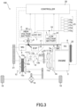
- the vehicle 100 illustrated in FIG. 3 further includes a motor-generator 4 (hereinafter referred to as "MG 4.") as a driving source for running.
- MG 4. motor-generator 4
- the MG 4 is a synchronous rotating electrical machine in which a permanent magnet is embedded in a rotor, and a stator coil is wound around a stator.
- the MG 4 is connected to a shaft of the primary pulley 13a via a chain 21 wound between a sprocket disposed on a shaft of the MG 4 and a sprocket disposed on the shaft of the primary pulley 13a.
- the MG 4 is controlled by applying a three-phase alternating current generated by the inverter 8 on the basis of a command from the controller 20.
- the MG 4 operates as an electric motor that receives the electric power supplied from the high voltage battery 2 to rotatably drive, thus generating a torque for driving the vehicle 100.
- the MG 4 functions as an electric generator that generates an electromotive force on both ends of the stator coil when the rotor receives the rotational energy from the engine 3 and the drive wheels 18, thus allowing the high voltage battery 2 to be charged. It should be noted that the MG 4 corresponds to the first rotating electrical machine.
- the vehicle 100 of this embodiment includes the engine 3, the first battery (low voltage battery 1), the second battery (high voltage battery 2), the first rotating electrical machine (SG 6, MG 4), and the second rotating electrical machine (SM 5) for starting the engine 3.
- the first battery (low voltage battery 1) is constituted by a lithium-ion battery and supplies an electric power to the electric component 15 mounted to the vehicle 100.
- the second battery (high voltage battery 2) is constituted by a lithium-ion battery and has an output voltage higher than an output voltage of the first battery (low voltage battery 1).
- the first rotating electrical machine (SG 6, MG 4) operates by an electric power supplied from the second battery (high voltage battery 2) and generates a torque for driving the vehicle 100.
- the second rotating electrical machine (SM 5) operates by an electric power supplied from the second battery (high voltage battery 2).
- the engine 3 can be reliably started also at the very low temperature.
- the first battery (low voltage battery 1) and the second battery (high voltage battery 2) are constituted by a lithium-ion battery, the reliability of the power supply system can be improved.
- the vehicle 100 includes the SG 6 as the first rotating electrical machine.
- the SG 6 generates a torque for starting the engine 3 or assisting driving of the engine 3 when an electric power is supplied from the high voltage battery 2.
- the SG 6 is allowed to generate an electric power for charging the low voltage battery 1 and the high voltage battery 2 when receiving a rotational energy from the engine 3.
- the vehicle 100 includes the MG 4 as the first rotating electrical machine.
- the MG 4 generates a torque for driving the drive wheels 18 when an electric power is supplied from the high voltage battery 2.
- the MG 4 is allowed to generate an electric power for charging the low voltage battery 1 and the high voltage battery 2 when an input from the drive wheels 18 or the engine 3 is present.
- the vehicle 100 including the MG 4 is, what is called, a strong hybrid vehicle and is equipped with the high voltage battery 2, a battery can be shared by the MG 4 and the SM 5.
- the vehicle 100 further includes the DC-DC converter 7, the first remaining capacity detector 31 (battery remaining capacity detecting means), and the controller 20 (control means).
- the DC-DC converter 7 is disposed on an electric circuit connecting the low voltage battery 1 to the high voltage battery 2, converts an input voltage, and outputs the converted voltage.
- the first remaining capacity detector 31 detects the remaining capacity SOC1 of the low voltage battery 1.
- the controller 20 performs a charge control of the low voltage battery 1 and the high voltage battery 2.
- the controller 20 activates the DC-DC converter 7 to charge the low voltage battery 1 by the electric power of the high voltage battery 2 when the remaining capacity SOC1 of the low voltage battery 1 is detected to fall below the predetermined value E1 when the ignition is OFF.
- the remaining capacity SOC1 is detected by the first remaining capacity detector 31.
- the controller 20 charges the low voltage battery 1 by using the high voltage battery 2. Accordingly, in, for example, parking for a long period, the backup of the electric component 15, and the like can be continuously performed.
Landscapes
- Engineering & Computer Science (AREA)
- Transportation (AREA)
- Mechanical Engineering (AREA)
- Chemical & Material Sciences (AREA)
- Combustion & Propulsion (AREA)
- Power Engineering (AREA)
- Sustainable Development (AREA)
- Sustainable Energy (AREA)
- Life Sciences & Earth Sciences (AREA)
- Automation & Control Theory (AREA)
- Health & Medical Sciences (AREA)
- Biomedical Technology (AREA)
- General Health & Medical Sciences (AREA)
- Electric Propulsion And Braking For Vehicles (AREA)
- Hybrid Electric Vehicles (AREA)
- Control Of Charge By Means Of Generators (AREA)
- Charge And Discharge Circuits For Batteries Or The Like (AREA)
Applications Claiming Priority (2)
| Application Number | Priority Date | Filing Date | Title |
|---|---|---|---|
| JP2019115813 | 2019-06-21 | ||
| PCT/JP2020/021620 WO2020255690A1 (ja) | 2019-06-21 | 2020-06-01 | 車両 |
Publications (3)
| Publication Number | Publication Date |
|---|---|
| EP3988413A1 EP3988413A1 (en) | 2022-04-27 |
| EP3988413A4 EP3988413A4 (en) | 2022-11-02 |
| EP3988413B1 true EP3988413B1 (en) | 2024-09-04 |
Family
ID=74037108
Family Applications (1)
| Application Number | Title | Priority Date | Filing Date |
|---|---|---|---|
| EP20825118.1A Active EP3988413B1 (en) | 2019-06-21 | 2020-06-01 | Vehicle |
Country Status (5)
| Country | Link |
|---|---|
| US (1) | US11766927B2 (enExample) |
| EP (1) | EP3988413B1 (enExample) |
| JP (1) | JP7219338B2 (enExample) |
| CN (1) | CN114126939B (enExample) |
| WO (1) | WO2020255690A1 (enExample) |
Families Citing this family (5)
| Publication number | Priority date | Publication date | Assignee | Title |
|---|---|---|---|---|
| WO2020255691A1 (ja) * | 2019-06-21 | 2020-12-24 | ジヤトコ株式会社 | 車両の電源装置及びその制御方法 |
| KR20240033725A (ko) * | 2022-09-02 | 2024-03-13 | 현대자동차주식회사 | 하이브리드 자동차 및 그의 주행 제어 방법 |
| JP2024046453A (ja) * | 2022-09-22 | 2024-04-03 | 株式会社Subaru | ハイブリッド車 |
| WO2025173123A1 (ja) * | 2024-02-14 | 2025-08-21 | 株式会社Subaru | 車両用充電制御装置 |
| WO2025173124A1 (ja) * | 2024-02-14 | 2025-08-21 | 株式会社Subaru | 車両用充電制御装置 |
Family Cites Families (23)
| Publication number | Priority date | Publication date | Assignee | Title |
|---|---|---|---|---|
| JP3673200B2 (ja) * | 2001-09-14 | 2005-07-20 | 本田技研工業株式会社 | ハイブリッド車両の制御装置 |
| US6962135B2 (en) * | 2002-01-31 | 2005-11-08 | Visteon Global Technologies, Inc. | Use of integrated starter alternator to prevent engine stall |
| JP3812459B2 (ja) * | 2002-02-26 | 2006-08-23 | トヨタ自動車株式会社 | 車両の電源制御装置 |
| JP2005086988A (ja) | 2003-09-11 | 2005-03-31 | Honda Motor Co Ltd | ハイブリッド車両の制御装置 |
| JP4218634B2 (ja) | 2004-12-16 | 2009-02-04 | 株式会社デンソー | ハイブリッド型車両の充電制御装置 |
| JP5171578B2 (ja) * | 2008-12-01 | 2013-03-27 | 日立オートモティブシステムズ株式会社 | 車両用バッテリー制御装置 |
| JP5446283B2 (ja) | 2009-01-23 | 2014-03-19 | 日産自動車株式会社 | 車両用充電制御装置 |
| JP2011055581A (ja) * | 2009-08-31 | 2011-03-17 | Toyota Motor Corp | 駆動システムおよび自動車 |
| JP2011208599A (ja) * | 2010-03-30 | 2011-10-20 | Panasonic Corp | 車両用電源装置 |
| JP5505335B2 (ja) * | 2011-02-28 | 2014-05-28 | 株式会社デンソー | 車両用動力伝達装置 |
| JP5836068B2 (ja) | 2011-10-31 | 2015-12-24 | 日立オートモティブシステムズ株式会社 | 車両用電源装置、電動車両 |
| JP6097152B2 (ja) | 2013-05-27 | 2017-03-15 | 本田技研工業株式会社 | 電動車両 |
| JP6156248B2 (ja) * | 2014-05-07 | 2017-07-05 | 株式会社デンソー | 制御装置 |
| WO2015189902A1 (ja) * | 2014-06-09 | 2015-12-17 | 日産自動車株式会社 | 車両用電気回路 |
| US9969292B2 (en) * | 2014-11-14 | 2018-05-15 | Johnson Controls Technology Company | Semi-active partial parallel battery architecture for an automotive vehicle systems and methods |
| JP6350257B2 (ja) | 2014-12-16 | 2018-07-04 | 株式会社デンソー | 通信方法 |
| JP6553916B2 (ja) * | 2015-03-31 | 2019-07-31 | 株式会社Subaru | 車両用電源装置 |
| CN106300472B (zh) * | 2015-05-29 | 2019-08-09 | 长城汽车股份有限公司 | 一种电池系统及其控制方法 |
| JP6409735B2 (ja) * | 2015-10-16 | 2018-10-24 | 株式会社デンソー | ハイブリッド車の制御装置 |
| JP2017118775A (ja) * | 2015-12-25 | 2017-06-29 | 株式会社デンソー | 電源システム |
| JP2017118755A (ja) * | 2015-12-25 | 2017-06-29 | シャープ株式会社 | モータ駆動制御装置およびヒートポンプ機器 |
| KR20190072936A (ko) * | 2017-12-18 | 2019-06-26 | 현대자동차주식회사 | 마일드 하이브리드 차량의 엔진 시동 장치 및 방법 |
| JP6807977B2 (ja) | 2019-04-25 | 2021-01-06 | 株式会社 ディー・エヌ・エー | 情報処理装置、ゲームプログラム、及び、情報処理方法 |
-
2020
- 2020-06-01 US US17/614,942 patent/US11766927B2/en active Active
- 2020-06-01 EP EP20825118.1A patent/EP3988413B1/en active Active
- 2020-06-01 CN CN202080045583.3A patent/CN114126939B/zh active Active
- 2020-06-01 JP JP2021527538A patent/JP7219338B2/ja active Active
- 2020-06-01 WO PCT/JP2020/021620 patent/WO2020255690A1/ja not_active Ceased
Also Published As
| Publication number | Publication date |
|---|---|
| US20220234436A1 (en) | 2022-07-28 |
| EP3988413A4 (en) | 2022-11-02 |
| CN114126939A (zh) | 2022-03-01 |
| EP3988413A1 (en) | 2022-04-27 |
| JP7219338B2 (ja) | 2023-02-07 |
| CN114126939B (zh) | 2024-10-01 |
| JPWO2020255690A1 (enExample) | 2020-12-24 |
| US11766927B2 (en) | 2023-09-26 |
| WO2020255690A1 (ja) | 2020-12-24 |
Similar Documents
| Publication | Publication Date | Title |
|---|---|---|
| EP3988413B1 (en) | Vehicle | |
| US8606450B2 (en) | Hybrid powertrain with geared starter motor and belt alternator starter and method of restarting an engine | |
| US10436167B1 (en) | Starter system and method of control | |
| US20160214503A1 (en) | Hybrid vehicle control device | |
| US10385818B2 (en) | Vehicle control apparatus | |
| US9586469B2 (en) | Hybrid vehicle control device | |
| WO2020017168A1 (ja) | ハイブリッド車両の電力制御装置及び電力制御方法 | |
| US12397647B2 (en) | Power supply device for vehicle and control method for the same | |
| JP2021000926A (ja) | ハイブリッド車両及びその制御方法 | |
| JP6079521B2 (ja) | ハイブリッド車両 | |
| WO2016035791A1 (ja) | ハイブリッド車両用油圧制御装置 | |
| JP2000145497A (ja) | 動力装置の始動制御装置 | |
| JP2021000924A (ja) | 車両及び車両の制御方法 | |
| JP2021000927A (ja) | 車両 | |
| JP2000253507A (ja) | ハイブリッド車両の制御装置 | |
| JP2020197259A (ja) | 車両及び車両の制御方法 | |
| JP2020196381A (ja) | 車両及び車両の制御方法 | |
| JP2015094433A (ja) | 車両及び潤滑制御方法 | |
| JP7372764B2 (ja) | ハイブリッド車両及びハイブリッド車両の制御方法 | |
| JP7219175B2 (ja) | 車両及びオイルポンプ駆動制御方法 | |
| JP7294911B2 (ja) | ハイブリッド車両 | |
| JP2021000929A (ja) | ハイブリッド車両及びその制御方法 | |
| JP2021000922A (ja) | ハイブリッド車両及びハイブリッド車両の制御方法 | |
| KR102451875B1 (ko) | 차량의 제어 방법 | |
| JP2017177969A (ja) | ハイブリッド車両システム、ハイブリッド車両システムの制御装置及びハイブリッド車両システムの制御方法 |
Legal Events
| Date | Code | Title | Description |
|---|---|---|---|
| STAA | Information on the status of an ep patent application or granted ep patent |
Free format text: STATUS: THE INTERNATIONAL PUBLICATION HAS BEEN MADE |
|
| PUAI | Public reference made under article 153(3) epc to a published international application that has entered the european phase |
Free format text: ORIGINAL CODE: 0009012 |
|
| STAA | Information on the status of an ep patent application or granted ep patent |
Free format text: STATUS: REQUEST FOR EXAMINATION WAS MADE |
|
| 17P | Request for examination filed |
Effective date: 20211119 |
|
| AK | Designated contracting states |
Kind code of ref document: A1 Designated state(s): AL AT BE BG CH CY CZ DE DK EE ES FI FR GB GR HR HU IE IS IT LI LT LU LV MC MK MT NL NO PL PT RO RS SE SI SK SM TR |
|
| RAP3 | Party data changed (applicant data changed or rights of an application transferred) |
Owner name: RENAULT S.A.S Owner name: NISSAN MOTOR CO., LTD. Owner name: JATCO LTD |
|
| DAV | Request for validation of the european patent (deleted) | ||
| DAX | Request for extension of the european patent (deleted) | ||
| A4 | Supplementary search report drawn up and despatched |
Effective date: 20220930 |
|
| RIC1 | Information provided on ipc code assigned before grant |
Ipc: H02J 7/16 20060101ALI20220926BHEP Ipc: H02J 7/02 20160101ALI20220926BHEP Ipc: H02J 7/00 20060101ALI20220926BHEP Ipc: B60W 10/26 20060101ALI20220926BHEP Ipc: B60W 10/08 20060101ALI20220926BHEP Ipc: B60L 58/20 20190101ALI20220926BHEP Ipc: B60L 50/16 20190101ALI20220926BHEP Ipc: B60L 1/00 20060101ALI20220926BHEP Ipc: B60K 6/485 20071001ALI20220926BHEP Ipc: B60W 20/50 20160101AFI20220926BHEP |
|
| GRAP | Despatch of communication of intention to grant a patent |
Free format text: ORIGINAL CODE: EPIDOSNIGR1 |
|
| STAA | Information on the status of an ep patent application or granted ep patent |
Free format text: STATUS: GRANT OF PATENT IS INTENDED |
|
| INTG | Intention to grant announced |
Effective date: 20240619 |
|
| GRAS | Grant fee paid |
Free format text: ORIGINAL CODE: EPIDOSNIGR3 |
|
| GRAA | (expected) grant |
Free format text: ORIGINAL CODE: 0009210 |
|
| STAA | Information on the status of an ep patent application or granted ep patent |
Free format text: STATUS: THE PATENT HAS BEEN GRANTED |
|
| AK | Designated contracting states |
Kind code of ref document: B1 Designated state(s): AL AT BE BG CH CY CZ DE DK EE ES FI FR GB GR HR HU IE IS IT LI LT LU LV MC MK MT NL NO PL PT RO RS SE SI SK SM TR |
|
| REG | Reference to a national code |
Ref country code: GB Ref legal event code: FG4D |
|
| REG | Reference to a national code |
Ref country code: CH Ref legal event code: EP |
|
| REG | Reference to a national code |
Ref country code: IE Ref legal event code: FG4D |
|
| REG | Reference to a national code |
Ref country code: DE Ref legal event code: R096 Ref document number: 602020037224 Country of ref document: DE |
|
| REG | Reference to a national code |
Ref country code: LT Ref legal event code: MG9D |
|
| REG | Reference to a national code |
Ref country code: NL Ref legal event code: MP Effective date: 20240904 |
|
| PG25 | Lapsed in a contracting state [announced via postgrant information from national office to epo] |
Ref country code: NO Free format text: LAPSE BECAUSE OF FAILURE TO SUBMIT A TRANSLATION OF THE DESCRIPTION OR TO PAY THE FEE WITHIN THE PRESCRIBED TIME-LIMIT Effective date: 20241204 |
|
| PG25 | Lapsed in a contracting state [announced via postgrant information from national office to epo] |
Ref country code: GR Free format text: LAPSE BECAUSE OF FAILURE TO SUBMIT A TRANSLATION OF THE DESCRIPTION OR TO PAY THE FEE WITHIN THE PRESCRIBED TIME-LIMIT Effective date: 20241205 Ref country code: PL Free format text: LAPSE BECAUSE OF FAILURE TO SUBMIT A TRANSLATION OF THE DESCRIPTION OR TO PAY THE FEE WITHIN THE PRESCRIBED TIME-LIMIT Effective date: 20240904 Ref country code: FI Free format text: LAPSE BECAUSE OF FAILURE TO SUBMIT A TRANSLATION OF THE DESCRIPTION OR TO PAY THE FEE WITHIN THE PRESCRIBED TIME-LIMIT Effective date: 20240904 |
|
| PG25 | Lapsed in a contracting state [announced via postgrant information from national office to epo] |
Ref country code: BG Free format text: LAPSE BECAUSE OF FAILURE TO SUBMIT A TRANSLATION OF THE DESCRIPTION OR TO PAY THE FEE WITHIN THE PRESCRIBED TIME-LIMIT Effective date: 20240904 |
|
| PG25 | Lapsed in a contracting state [announced via postgrant information from national office to epo] |
Ref country code: LV Free format text: LAPSE BECAUSE OF FAILURE TO SUBMIT A TRANSLATION OF THE DESCRIPTION OR TO PAY THE FEE WITHIN THE PRESCRIBED TIME-LIMIT Effective date: 20240904 |
|
| PG25 | Lapsed in a contracting state [announced via postgrant information from national office to epo] |
Ref country code: HR Free format text: LAPSE BECAUSE OF FAILURE TO SUBMIT A TRANSLATION OF THE DESCRIPTION OR TO PAY THE FEE WITHIN THE PRESCRIBED TIME-LIMIT Effective date: 20240904 |
|
| PG25 | Lapsed in a contracting state [announced via postgrant information from national office to epo] |
Ref country code: ES Free format text: LAPSE BECAUSE OF FAILURE TO SUBMIT A TRANSLATION OF THE DESCRIPTION OR TO PAY THE FEE WITHIN THE PRESCRIBED TIME-LIMIT Effective date: 20240904 Ref country code: RS Free format text: LAPSE BECAUSE OF FAILURE TO SUBMIT A TRANSLATION OF THE DESCRIPTION OR TO PAY THE FEE WITHIN THE PRESCRIBED TIME-LIMIT Effective date: 20241204 |
|
| PG25 | Lapsed in a contracting state [announced via postgrant information from national office to epo] |
Ref country code: RS Free format text: LAPSE BECAUSE OF FAILURE TO SUBMIT A TRANSLATION OF THE DESCRIPTION OR TO PAY THE FEE WITHIN THE PRESCRIBED TIME-LIMIT Effective date: 20241204 Ref country code: PL Free format text: LAPSE BECAUSE OF FAILURE TO SUBMIT A TRANSLATION OF THE DESCRIPTION OR TO PAY THE FEE WITHIN THE PRESCRIBED TIME-LIMIT Effective date: 20240904 Ref country code: NO Free format text: LAPSE BECAUSE OF FAILURE TO SUBMIT A TRANSLATION OF THE DESCRIPTION OR TO PAY THE FEE WITHIN THE PRESCRIBED TIME-LIMIT Effective date: 20241204 Ref country code: LV Free format text: LAPSE BECAUSE OF FAILURE TO SUBMIT A TRANSLATION OF THE DESCRIPTION OR TO PAY THE FEE WITHIN THE PRESCRIBED TIME-LIMIT Effective date: 20240904 Ref country code: HR Free format text: LAPSE BECAUSE OF FAILURE TO SUBMIT A TRANSLATION OF THE DESCRIPTION OR TO PAY THE FEE WITHIN THE PRESCRIBED TIME-LIMIT Effective date: 20240904 Ref country code: GR Free format text: LAPSE BECAUSE OF FAILURE TO SUBMIT A TRANSLATION OF THE DESCRIPTION OR TO PAY THE FEE WITHIN THE PRESCRIBED TIME-LIMIT Effective date: 20241205 Ref country code: FI Free format text: LAPSE BECAUSE OF FAILURE TO SUBMIT A TRANSLATION OF THE DESCRIPTION OR TO PAY THE FEE WITHIN THE PRESCRIBED TIME-LIMIT Effective date: 20240904 Ref country code: ES Free format text: LAPSE BECAUSE OF FAILURE TO SUBMIT A TRANSLATION OF THE DESCRIPTION OR TO PAY THE FEE WITHIN THE PRESCRIBED TIME-LIMIT Effective date: 20240904 Ref country code: BG Free format text: LAPSE BECAUSE OF FAILURE TO SUBMIT A TRANSLATION OF THE DESCRIPTION OR TO PAY THE FEE WITHIN THE PRESCRIBED TIME-LIMIT Effective date: 20240904 |
|
| REG | Reference to a national code |
Ref country code: AT Ref legal event code: MK05 Ref document number: 1720078 Country of ref document: AT Kind code of ref document: T Effective date: 20240904 |
|
| PG25 | Lapsed in a contracting state [announced via postgrant information from national office to epo] |
Ref country code: NL Free format text: LAPSE BECAUSE OF FAILURE TO SUBMIT A TRANSLATION OF THE DESCRIPTION OR TO PAY THE FEE WITHIN THE PRESCRIBED TIME-LIMIT Effective date: 20240904 |
|
| PG25 | Lapsed in a contracting state [announced via postgrant information from national office to epo] |
Ref country code: PT Free format text: LAPSE BECAUSE OF FAILURE TO SUBMIT A TRANSLATION OF THE DESCRIPTION OR TO PAY THE FEE WITHIN THE PRESCRIBED TIME-LIMIT Effective date: 20250106 Ref country code: IS Free format text: LAPSE BECAUSE OF FAILURE TO SUBMIT A TRANSLATION OF THE DESCRIPTION OR TO PAY THE FEE WITHIN THE PRESCRIBED TIME-LIMIT Effective date: 20250104 |
|
| PG25 | Lapsed in a contracting state [announced via postgrant information from national office to epo] |
Ref country code: RO Free format text: LAPSE BECAUSE OF FAILURE TO SUBMIT A TRANSLATION OF THE DESCRIPTION OR TO PAY THE FEE WITHIN THE PRESCRIBED TIME-LIMIT Effective date: 20240904 Ref country code: SM Free format text: LAPSE BECAUSE OF FAILURE TO SUBMIT A TRANSLATION OF THE DESCRIPTION OR TO PAY THE FEE WITHIN THE PRESCRIBED TIME-LIMIT Effective date: 20240904 |
|
| PG25 | Lapsed in a contracting state [announced via postgrant information from national office to epo] |
Ref country code: EE Free format text: LAPSE BECAUSE OF FAILURE TO SUBMIT A TRANSLATION OF THE DESCRIPTION OR TO PAY THE FEE WITHIN THE PRESCRIBED TIME-LIMIT Effective date: 20240904 Ref country code: AT Free format text: LAPSE BECAUSE OF FAILURE TO SUBMIT A TRANSLATION OF THE DESCRIPTION OR TO PAY THE FEE WITHIN THE PRESCRIBED TIME-LIMIT Effective date: 20240904 |
|
| PG25 | Lapsed in a contracting state [announced via postgrant information from national office to epo] |
Ref country code: CZ Free format text: LAPSE BECAUSE OF FAILURE TO SUBMIT A TRANSLATION OF THE DESCRIPTION OR TO PAY THE FEE WITHIN THE PRESCRIBED TIME-LIMIT Effective date: 20240904 |
|
| PG25 | Lapsed in a contracting state [announced via postgrant information from national office to epo] |
Ref country code: IT Free format text: LAPSE BECAUSE OF FAILURE TO SUBMIT A TRANSLATION OF THE DESCRIPTION OR TO PAY THE FEE WITHIN THE PRESCRIBED TIME-LIMIT Effective date: 20240904 Ref country code: SK Free format text: LAPSE BECAUSE OF FAILURE TO SUBMIT A TRANSLATION OF THE DESCRIPTION OR TO PAY THE FEE WITHIN THE PRESCRIBED TIME-LIMIT Effective date: 20240904 |
|
| REG | Reference to a national code |
Ref country code: DE Ref legal event code: R097 Ref document number: 602020037224 Country of ref document: DE |
|
| PGFP | Annual fee paid to national office [announced via postgrant information from national office to epo] |
Ref country code: DE Payment date: 20250630 Year of fee payment: 6 |
|
| PG25 | Lapsed in a contracting state [announced via postgrant information from national office to epo] |
Ref country code: DK Free format text: LAPSE BECAUSE OF FAILURE TO SUBMIT A TRANSLATION OF THE DESCRIPTION OR TO PAY THE FEE WITHIN THE PRESCRIBED TIME-LIMIT Effective date: 20240904 |
|
| PGFP | Annual fee paid to national office [announced via postgrant information from national office to epo] |
Ref country code: GB Payment date: 20250620 Year of fee payment: 6 |
|
| PLBE | No opposition filed within time limit |
Free format text: ORIGINAL CODE: 0009261 |
|
| STAA | Information on the status of an ep patent application or granted ep patent |
Free format text: STATUS: NO OPPOSITION FILED WITHIN TIME LIMIT |
|
| PGFP | Annual fee paid to national office [announced via postgrant information from national office to epo] |
Ref country code: FR Payment date: 20250618 Year of fee payment: 6 |
|
| RAP2 | Party data changed (patent owner data changed or rights of a patent transferred) |
Owner name: JATCO LTD Owner name: NISSAN MOTOR CO., LTD. Owner name: HORSE POWERTRAIN SOLUTIONS, S.L. |
|
| 26N | No opposition filed |
Effective date: 20250605 |
|
| PG25 | Lapsed in a contracting state [announced via postgrant information from national office to epo] |
Ref country code: SE Free format text: LAPSE BECAUSE OF FAILURE TO SUBMIT A TRANSLATION OF THE DESCRIPTION OR TO PAY THE FEE WITHIN THE PRESCRIBED TIME-LIMIT Effective date: 20240904 |