EP3975854B1 - Ct imaging apparatus - Google Patents
Ct imaging apparatus Download PDFInfo
- Publication number
- EP3975854B1 EP3975854B1 EP20819168.4A EP20819168A EP3975854B1 EP 3975854 B1 EP3975854 B1 EP 3975854B1 EP 20819168 A EP20819168 A EP 20819168A EP 3975854 B1 EP3975854 B1 EP 3975854B1
- Authority
- EP
- European Patent Office
- Prior art keywords
- elongated frame
- frame part
- construction
- elongated
- essentially
- Prior art date
- Legal status (The legal status is an assumption and is not a legal conclusion. Google has not performed a legal analysis and makes no representation as to the accuracy of the status listed.)
- Active
Links
Images


Classifications
-
- A—HUMAN NECESSITIES
- A61—MEDICAL OR VETERINARY SCIENCE; HYGIENE
- A61B—DIAGNOSIS; SURGERY; IDENTIFICATION
- A61B5/00—Measuring for diagnostic purposes; Identification of persons
- A61B5/0059—Measuring for diagnostic purposes; Identification of persons using light, e.g. diagnosis by transillumination, diascopy, fluorescence
- A61B5/0082—Measuring for diagnostic purposes; Identification of persons using light, e.g. diagnosis by transillumination, diascopy, fluorescence adapted for particular medical purposes
- A61B5/0088—Measuring for diagnostic purposes; Identification of persons using light, e.g. diagnosis by transillumination, diascopy, fluorescence adapted for particular medical purposes for oral or dental tissue
-
- A—HUMAN NECESSITIES
- A61—MEDICAL OR VETERINARY SCIENCE; HYGIENE
- A61B—DIAGNOSIS; SURGERY; IDENTIFICATION
- A61B6/00—Apparatus or devices for radiation diagnosis; Apparatus or devices for radiation diagnosis combined with radiation therapy equipment
- A61B6/02—Arrangements for diagnosis sequentially in different planes; Stereoscopic radiation diagnosis
- A61B6/03—Computed tomography [CT]
- A61B6/032—Transmission computed tomography [CT]
- A61B6/035—Mechanical aspects of CT
-
- A—HUMAN NECESSITIES
- A61—MEDICAL OR VETERINARY SCIENCE; HYGIENE
- A61B—DIAGNOSIS; SURGERY; IDENTIFICATION
- A61B6/00—Apparatus or devices for radiation diagnosis; Apparatus or devices for radiation diagnosis combined with radiation therapy equipment
- A61B6/04—Positioning of patients; Tiltable beds or the like
- A61B6/0407—Supports, e.g. tables or beds, for the body or parts of the body
- A61B6/0442—Supports, e.g. tables or beds, for the body or parts of the body made of non-metallic materials
-
- A—HUMAN NECESSITIES
- A61—MEDICAL OR VETERINARY SCIENCE; HYGIENE
- A61B—DIAGNOSIS; SURGERY; IDENTIFICATION
- A61B6/00—Apparatus or devices for radiation diagnosis; Apparatus or devices for radiation diagnosis combined with radiation therapy equipment
- A61B6/04—Positioning of patients; Tiltable beds or the like
- A61B6/0487—Motor-assisted positioning
-
- A—HUMAN NECESSITIES
- A61—MEDICAL OR VETERINARY SCIENCE; HYGIENE
- A61B—DIAGNOSIS; SURGERY; IDENTIFICATION
- A61B6/00—Apparatus or devices for radiation diagnosis; Apparatus or devices for radiation diagnosis combined with radiation therapy equipment
- A61B6/08—Auxiliary means for directing the radiation beam to a particular spot, e.g. using light beams
-
- A—HUMAN NECESSITIES
- A61—MEDICAL OR VETERINARY SCIENCE; HYGIENE
- A61B—DIAGNOSIS; SURGERY; IDENTIFICATION
- A61B6/00—Apparatus or devices for radiation diagnosis; Apparatus or devices for radiation diagnosis combined with radiation therapy equipment
- A61B6/40—Arrangements for generating radiation specially adapted for radiation diagnosis
- A61B6/4064—Arrangements for generating radiation specially adapted for radiation diagnosis specially adapted for producing a particular type of beam
- A61B6/4085—Cone-beams
-
- A—HUMAN NECESSITIES
- A61—MEDICAL OR VETERINARY SCIENCE; HYGIENE
- A61B—DIAGNOSIS; SURGERY; IDENTIFICATION
- A61B6/00—Apparatus or devices for radiation diagnosis; Apparatus or devices for radiation diagnosis combined with radiation therapy equipment
- A61B6/44—Constructional features of apparatus for radiation diagnosis
- A61B6/4429—Constructional features of apparatus for radiation diagnosis related to the mounting of source units and detector units
- A61B6/4435—Constructional features of apparatus for radiation diagnosis related to the mounting of source units and detector units the source unit and the detector unit being coupled by a rigid structure
-
- A—HUMAN NECESSITIES
- A61—MEDICAL OR VETERINARY SCIENCE; HYGIENE
- A61B—DIAGNOSIS; SURGERY; IDENTIFICATION
- A61B6/00—Apparatus or devices for radiation diagnosis; Apparatus or devices for radiation diagnosis combined with radiation therapy equipment
- A61B6/44—Constructional features of apparatus for radiation diagnosis
- A61B6/4429—Constructional features of apparatus for radiation diagnosis related to the mounting of source units and detector units
- A61B6/4452—Constructional features of apparatus for radiation diagnosis related to the mounting of source units and detector units the source unit and the detector unit being able to move relative to each other
-
- A—HUMAN NECESSITIES
- A61—MEDICAL OR VETERINARY SCIENCE; HYGIENE
- A61B—DIAGNOSIS; SURGERY; IDENTIFICATION
- A61B6/00—Apparatus or devices for radiation diagnosis; Apparatus or devices for radiation diagnosis combined with radiation therapy equipment
- A61B6/44—Constructional features of apparatus for radiation diagnosis
- A61B6/4429—Constructional features of apparatus for radiation diagnosis related to the mounting of source units and detector units
- A61B6/4458—Constructional features of apparatus for radiation diagnosis related to the mounting of source units and detector units the source unit or the detector unit being attached to robotic arms
-
- A—HUMAN NECESSITIES
- A61—MEDICAL OR VETERINARY SCIENCE; HYGIENE
- A61B—DIAGNOSIS; SURGERY; IDENTIFICATION
- A61B6/00—Apparatus or devices for radiation diagnosis; Apparatus or devices for radiation diagnosis combined with radiation therapy equipment
- A61B6/44—Constructional features of apparatus for radiation diagnosis
- A61B6/4476—Constructional features of apparatus for radiation diagnosis related to motor-assisted motion of the source unit
-
- A—HUMAN NECESSITIES
- A61—MEDICAL OR VETERINARY SCIENCE; HYGIENE
- A61B—DIAGNOSIS; SURGERY; IDENTIFICATION
- A61B6/00—Apparatus or devices for radiation diagnosis; Apparatus or devices for radiation diagnosis combined with radiation therapy equipment
- A61B6/50—Apparatus or devices for radiation diagnosis; Apparatus or devices for radiation diagnosis combined with radiation therapy equipment specially adapted for specific body parts; specially adapted for specific clinical applications
- A61B6/51—Apparatus or devices for radiation diagnosis; Apparatus or devices for radiation diagnosis combined with radiation therapy equipment specially adapted for specific body parts; specially adapted for specific clinical applications for dentistry
- A61B6/512—Intraoral means
-
- A—HUMAN NECESSITIES
- A61—MEDICAL OR VETERINARY SCIENCE; HYGIENE
- A61B—DIAGNOSIS; SURGERY; IDENTIFICATION
- A61B6/00—Apparatus or devices for radiation diagnosis; Apparatus or devices for radiation diagnosis combined with radiation therapy equipment
- A61B6/54—Control of apparatus or devices for radiation diagnosis
-
- A—HUMAN NECESSITIES
- A61—MEDICAL OR VETERINARY SCIENCE; HYGIENE
- A61B—DIAGNOSIS; SURGERY; IDENTIFICATION
- A61B6/00—Apparatus or devices for radiation diagnosis; Apparatus or devices for radiation diagnosis combined with radiation therapy equipment
- A61B6/58—Testing, adjusting or calibrating thereof
- A61B6/587—Alignment of source unit to detector unit
-
- A—HUMAN NECESSITIES
- A61—MEDICAL OR VETERINARY SCIENCE; HYGIENE
- A61G—TRANSPORT, PERSONAL CONVEYANCES, OR ACCOMMODATION SPECIALLY ADAPTED FOR PATIENTS OR DISABLED PERSONS; OPERATING TABLES OR CHAIRS; CHAIRS FOR DENTISTRY; FUNERAL DEVICES
- A61G13/00—Operating tables; Auxiliary appliances therefor
- A61G13/02—Adjustable operating tables; Controls therefor
- A61G13/04—Adjustable operating tables; Controls therefor tiltable around transverse or longitudinal axis
-
- A—HUMAN NECESSITIES
- A61—MEDICAL OR VETERINARY SCIENCE; HYGIENE
- A61G—TRANSPORT, PERSONAL CONVEYANCES, OR ACCOMMODATION SPECIALLY ADAPTED FOR PATIENTS OR DISABLED PERSONS; OPERATING TABLES OR CHAIRS; CHAIRS FOR DENTISTRY; FUNERAL DEVICES
- A61G15/00—Operating chairs; Dental chairs; Accessories specially adapted therefor, e.g. work stands
- A61G15/02—Chairs with means to adjust position of patient; Controls therefor
-
- A—HUMAN NECESSITIES
- A61—MEDICAL OR VETERINARY SCIENCE; HYGIENE
- A61G—TRANSPORT, PERSONAL CONVEYANCES, OR ACCOMMODATION SPECIALLY ADAPTED FOR PATIENTS OR DISABLED PERSONS; OPERATING TABLES OR CHAIRS; CHAIRS FOR DENTISTRY; FUNERAL DEVICES
- A61G7/00—Beds specially adapted for nursing; Devices for lifting patients or disabled persons
- A61G7/002—Beds specially adapted for nursing; Devices for lifting patients or disabled persons having adjustable mattress frame
- A61G7/005—Beds specially adapted for nursing; Devices for lifting patients or disabled persons having adjustable mattress frame tiltable around transverse horizontal axis, e.g. for Trendelenburg position
-
- A—HUMAN NECESSITIES
- A61—MEDICAL OR VETERINARY SCIENCE; HYGIENE
- A61B—DIAGNOSIS; SURGERY; IDENTIFICATION
- A61B6/00—Apparatus or devices for radiation diagnosis; Apparatus or devices for radiation diagnosis combined with radiation therapy equipment
- A61B6/58—Testing, adjusting or calibrating thereof
- A61B6/588—Setting distance between source unit and detector unit
-
- A—HUMAN NECESSITIES
- A61—MEDICAL OR VETERINARY SCIENCE; HYGIENE
- A61G—TRANSPORT, PERSONAL CONVEYANCES, OR ACCOMMODATION SPECIALLY ADAPTED FOR PATIENTS OR DISABLED PERSONS; OPERATING TABLES OR CHAIRS; CHAIRS FOR DENTISTRY; FUNERAL DEVICES
- A61G2210/00—Devices for specific treatment or diagnosis
- A61G2210/50—Devices for specific treatment or diagnosis for radiography
Definitions
- the invention relates to computed tomography imaging apparatus.
- features of an apparatus according to the invention are applicable for use in the context of dental and medical cone beam computed tomography (CBCT) imaging apparatus.
- CBCT cone beam computed tomography
- Computed tomography is a kind of X-ray imaging in which a volume to be imaged is irradiated from different directions and, from the image information thus acquired, a desired two- or three-dimensional image can be reconstructed.
- Traditional CT apparatus are large and massive, and they are typically mounted on a floor.
- a patient is positioned for imaging within an examination opening of the apparatus, typically on a horizontally extending and laterally movable examination platform.
- CBCT cone beam computed tomography
- the object of the invention and of its preferable embodiments is a CT apparatus, especially a CBCT apparatus, applicable for versatile use and enabling imaging various parts of an anatomy in various ways.
- the characteristic features of the invention are defined in claim 1.
- Fig. 1 shows a schematic general side view of certain components of one embodiment, as an example, of a part of an apparatus according to the invention.
- the dental or medical CT imaging apparatus of Fig. 1 comprises an elongated frame part 11 extending in a first direction and having a first end and a second end. From this elongated frame part 11 extends in a second direction, which is substantially orthogonal to the first direction, a support construction 12 which supports an X-ray source 14 and an image detector 15 yet which as such are not visible in Fig. 1 .
- the X-ray source 14 and the image detector 15, which together form X-ray imaging means 14, 15, may be mounted to the support construction 12 essentially opposite to each other yet in embodiments, their mutual position may also be arranged to be adjustable.
- Fig. 1 further shows a patient support 18 which is a structure mechanically connected to the elongated frame part 11 and extending substantially in parallel with the elongated frame part 11.
- the patient support 18 is essentially of the same length as the elongated frame part 11.
- the length of the elongated frame part 11 is of the order of 240 cm.
- the length of the elongated frame part 11 is between 220 cm and 260 cm.
- the length of the patient support 18 is 80-90 % of the length of elongated frame part 11.
- the patient support 18 has a longer dimension in a first direction and a shorter dimension in a second direction orthogonal to the first direction.
- the patient support 18 is at least in the first direction at least for its prevailing part radiolucent.
- the radiolucent part of the patient support 18 is of essentially the same length as the elongated frame part 11.
- the patient support 18 comprises at least at either of its ends in the first direction a section which is not radiolucent.
- the length of the radiolucent part of the patient support 18 in the first direction is 80-90 % of the length of the elongated frame part 11.
- the support construction 12 supporting the X-ray imaging means 14, 15 is a circular gantry having a central axis 13.
- the gantry may partially encircle or completely house the X-ray imaging means 14, 15.
- the apparatus comprises a driving mechanism 16 arranged to drive the X-ray imaging means 14, 15 about a rotation axis.
- This rotation axis may coincide with the central axis 13 of the support construction 12 in form of the gantry and it may be a physical axis, or a virtual rotation axis as in the case of Fig. 1 .
- the central axis 13 of the gantry coincides the center of rotation / the rotation axis of the X-ray imaging means 14, 15 when they are driven along a curved path.
- the rotation axis is an instantaneous (virtual) rotation axis and the location of the instantaneous rotation axis in relation to the central axis 13 can be arranged to be changed.
- At least either of the components the ray source 14 and the image detector 15 is arranged to be laterally movable from a location exactly opposite to the other component.
- the structure 12 supporting the X-ray imaging means 14, 15 comprises a gantry having a central axis and the structures of apparatus allows for at least either of: laterally moving the X-ray source 14 between positions at which a central ray it generates coincides with the central axis of the gantry and a position at which the central ray it generates does not coincide with the central axis of the gantry; laterally moving the image detector 15 between positions at which a vector which is normal to the detector surface at the center of the image detector 15 coincides the central axis of the gantry and a position at which the vector which is normal to the detector surface at the center of the image detector 15 does not coincide the central axis of the gantry.
- the lateral moving of the X-ray imaging means 14, 15 may include moving the X-ray imaging means 14, 15 to a position at which they face each other while the central ray the X-ray source 14 generates does not coincide the central axis of the gantry and the vector which is normal to the detector surface at the center of the image detector 15 does not coincide the central axis of the gantry.
- another driving mechanism 17 is arranged to the apparatus to enable moving the support construction 12 back and forth in a direction which is substantially parallel with the direction in which the elongated frame part 11 extends. According to one aspect, that driving mechanism 17 may be arranged to move the support construction 12 along or alongside the elongated frame part 11.
- the driving mechanism 17 of the support construction 12 discussed above comprises a motor 110 and a gearing 111 arranged to rotate a pulley 112.
- the motor 110 and the pulley 112 are located at the proximity of the second end of the elongated frame part 11 there is also another pulley 112' at the proximity of the first end of the elongated frame part 11 and around the pulleys 112, 112' goes a belt 113, or a correspondingly functioning component like a chain.
- This mechanism is then functionally connected to the support construction 12 to drive it along the elongated frame part 11, such as shown as an example in Fig.
- grooves 114 are arranged to the elongated frame part 11 and, to the support construction 12, projecting parts 121 which are fitted to slide along the grooves 114.
- roller type linear guide ways are used in which case the motion is rather rolling than sliding.
- the driving mechanism to drive the support construction 12 comprises a motor arranged to the support construction 12 itself.
- the construction of the apparatus allows for driving the support construction 12 essentially the whole length between the first and second ends of the elongated frame part 11.
- the apparatus comprises a connection construction 19, 20 which connects the patient support 18 to the elongated frame part 11.
- the apparatus comprises a connection construction 19, 20 which mechanically connects the patient support 18 to the elongated frame part 11.
- connection construction 19, 20 may comprise a patient support adjustment mechanism 19', 20' configured to enable displacing the patient support 18 closer and further away from the elongated frame part 11.
- a driving mechanism 19'', 20'' is arranged in functional connection with the patient support adjustment mechanism 19', 20'.
- the patient support adjustment mechanism 19', 20' may comprise a first adjustment mechanism 19' arranged together with its driving mechanism 19'' comprised in the driving mechanism 19", 20'' substantially at the first end of the elongated frame part 11, and a second adjustment mechanism 20' arranged together with its driving mechanism 20" comprised in the driving mechanism 19", 20" substantially at the second end of the elongated frame part 11.
- the patient support adjustment mechanisms 19', 20' is arranged in functional connection with the control system of the apparatus and the control system is configured to control the driving mechanism 19", 20" of the adjustment mechanism 19', 20'.
- control system is configured to control the connection construction 19, 20 comprising the first adjustment mechanism 19' with its driving mechanism 19'', arranged substantially at the first end of the elongated frame part 11, and the second adjustment mechanism 20' with its driving mechanism 20'', arranged substantially at the second end of the elongated frame part 11, to keep at the first and second ends of the elongated frame part 11 an identical distance between the elongated frame part 11 and the patient support 18 when adjusting the distance between the two.
- the distance between the ends of the elongated frame part 11 and the patient support 18 can be adjusted to be different.
- the first and second adjustment mechanisms 19', 20' are arranged to be controlled independently.
- a holding structure 182 near the edges of the above-discussed cross section of the patient support construction 18 and on the side opposite to the for its prevailing part concave surface is arranged a holding structure 182.
- the holding structure 182 may be e.g. an elongated handle or an attachment structure to receive a strap designed to extent on or over the concave side of the patient support construction 18, to be used to provide further support to the patient and thus to help keeping still during an imaging exposure.
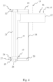
- FIG. 4 shows, as a schematic general side view, certain components of an embodiment, as an example, of an apparatus according to the invention in which, in addition to what can be referred to as a first elongated frame part 11 discussed above, there is a second elongated frame part 21 mechanically connected to the first elongated frame part 11 of essentially the same length as the first elongated frame part 11.
- an articulated connection construction 22 to mechanically connect the first and second elongated frame parts 11, 21, to allow for tilting of the first elongated frame part 11 about at least one tilt axis in relation to the second elongated frame part 21.
- the at least one tilt axis is orthogonal to both the abovementioned first and second directions in which the elongated frame part 11 and the support construction 12 extend.
- the tilt axis may be an axis which is orthogonal to the direction in which the first and second elongated frame parts 11, 21 extend as well as to direction in which the support construction 12 for the X-ray imaging assembly 14, 15 extends - perpendicularly from the first longitudinally extending frame part 11.
- the at least one tilt axis is horizontal. This is not to be understood that the tilt axis needs to be horizontal.
- a mounting structure 23 not directly visible in Fig. 4 is arranged in connection with the articulated connection construction 22.
- the mounting structure 23 is arranged movable along or alongside the second elongated frame part 21.
- a locking mechanism 24 configured to enable connecting and disconnecting the first and second elongated frame parts 11, 21.
- a locking mechanism 24 may be arranged at the proximity of the second end of the first and second elongated frame parts 11, 21, the locking mechanism being configured to enable connecting together and disconnecting the first and second elongated frame parts 11, 21 at the proximity of the second ends of the first and second elongated frame parts 11, 21.
- Fig. 5 shows the apparatus according to Fig. 4 at a stage where the first end of the first elongated frame part 11 has moved downwards and the second end of the first elongated frame part 11 has moved horizontally on a surface.
- the apparatus may be configured to allow for descending of the first end of the first elongated frame part 11 all the way to the proximity of the second end of the second elongated frame part 21.
- a driving mechanism 27 to drive the mounting structure 23 along or alongside the second elongated frame part 21.
- the driving mechanism 27 can move the first end of the first elongated frame part 11 in a direction in which the second elongated frame part 21 extends.
- the driving mechanism 27 to drive the mounting structure 23 may be a construction similar with the driving mechanism 17 driving the support construction 12 of the X-ray imaging means 14, 15 along or alongside the first elongated frame part 11.
- the driving mechanism 27 to drive the mounting structure 23 comprises a chain drive.
- a mounting structure 23 which is arranged movable along or alongside the second elongated frame part 21, such construction thereby providing a degree of freedom of movement along or alongside the second frame part 21 for the articulated connection construction 23 and for the first end of the first elongated frame part 11 mechanically connected to the articulated connection construction 23.
- the mounting structure 23 is arranged movable along or alongside the second elongated frame part 21 at least essentially a distance corresponding to the length of the first elongated frame part11, and the articulated connection construction 22 is arranged to allow for tilting of the first elongated frame part 11 between orientations at which the first and second elongated frame parts 11, 21 extend essentially in parallel and at which the first and second elongated frame parts 11, 21 extend essential orthogonally.
- the locking mechanism 24 comprises a displacement mechanism 25 which is not directly visible in Figs. discussed so far to move the second end of the first elongated frame part 11 a distance away from the second elongated frame part 21 when the locking mechanism 24 disconnects the first and second elongated frame parts 11, 21.
- the locking mechanism 24 comprises a motor driven arrangement with mating components on the side of a motorized structure and the first elongated frame part 11, respectively.
- the locking mechanism 24 may further comprise a guiding construction configured to guide the second end of the first elongated frame part 11 straight on the locking mechanism 24 when the second end of the first elongated frame part 11 is moving towards the locking mechanism 24. Or, to put it in other words, when the second end of the first elongated frame part 11 moves towards and approaches the second end of the second elongated frame part 21.
- the first elongated frame part 11 comprises at the proximity of its second end at least one wheel or roller 26.
- a structure designed to slide on a surface may be arranged at the second end of the first elongated frame part 11.
- FIG. 6 A more detailed embodiment concerning some of the features discussed above is presented in Fig. 6 , which overall shows the second ends of the first and second elongated frame parts 11, 21 yet wherein the very end of the second end of the first elongated frame parts 11 is cut, partly completely cut and partly just one wall being cut so that what could be called a back wall 11' is still visible.
- the embodiment shown in Fig. 6 includes a structure in which the displacement mechanism 25 comprises two toothed bars 31 mounted at the proximity of the second end of the second elongated frame part 21, to extent essentially orthogonally to the direction at which the second elongated frame part 21 extends, and two toothed wheels 32 mounted at the proximity of the second end of the first elongated frame part 11.
- the toothed wheels 32 are configured compatible with the toothed bars 31. While two toothed bars and wheels are shown, the number of those could be just one, or more than two.
- the embodiment shown in Fig. 6 further includes the displacement mechanism 25 comprising a displacing motor 33 arranged in functional connection with toothed wheels 32.
- the control system of the apparatus may be configured to, when the first and second elongated frame parts 11, 21 extend essentially in parallel and as a response to a control signal to alter the mutual orientation of the first and second elongated frame parts 11, 21, first operate the displacement mechanism 25 to move the second end of the first elongated frame part 11 a distance away from the second end of the second elongated frame part 21 and, second, operate said third driving mechanism 27 to drive the mounting structure 23 along or alongside the second elongated frame part 21 towards the second end of the second elongated frame part 21, so as to move the second end of the first elongated frame part 11 a further distance away from the second end of the second elongated frame part 21.
- the locking mechanism 24 shown in Fig. 6 further comprises a sensing element 29 configured to detect when the second end of the first elongated frame part 11, when moving towards the second end of the second elongated frame part 21, has reached a predefined locking position.
- the locking mechanism 24 shown in Fig. 6 further comprises a locking actuator 28 and the control system of the apparatus may be configured to, as a response to a control signal from the sensing element 29 that the second end of the first elongated frame part 11 when moving towards the second end of the second elongated frame part 21 has reached a predefined locking position, send a control signal to the locking actuator 28 to lock the second end of the first elongated frame part 11 at said predefined locking position.
- the guiding construction according the embodiment of Fig. 6 comprises two guide rails 30 mounted from their first end at the proximity of the second end of the second elongated frame part 21 and extending essentially orthogonally to the direction at which the second elongated frame part 21 extends, to form two guide passages. While two guide rails 30 are shown in Fig. 6 , the number of rails could be something else as well - yet, using just one rail it may be difficult to form a passage truly having a guiding function.
- the first elongated frame part 11 to comprise at the proximity of its second end two wheels, or rollers 26, at a first distance from each other, and the guiding construction to comprise two guide rails 30 to form two guide passages essentially at the same first distance from each other, the guide rails 30 further comprise at their second ends a beveling so as to make a distance between the guide passages smaller at that end of the passages than the first distance.
- Such construction aids in guiding the second end of the first elongated frame part 11 to find a designed passage to move towards the second elongated frame part 21.
- support construction 12 for the imaging means 15, 16 in a form of a gantry basically does not completely encircle the imaging means 14, 15 but functions primarily or solely as a support structure for holding the imaging means 14, 15, and structures arranged to the gantry to drive the imaging means 14, 15 about an axis.
- This kind of solution enables realizing the gantry as less heavy and as providing better access to the volume between the imaging means 14, 15, both physically and considering an area from where one may have a clear line of sight at that volume.
- Fig. 8 shows as a block diagram an example of components of a control system applicable for use in an apparatus according to this disclosure. In various embodiments, not all those features are necessarily present in a control system of the apparatus.
- the control system according to Fig. 8 is configured to enable controlling, first of all, operation of the X-ray source and the image detector.
- Components controlling operation of the X-ray source and the image detector can include components physically arranged to the Xx-ray source and/or the image detector and/or elsewhere in the apparatus.
- the control system of Fig. 8 further controls various driving means of the apparatus, such as those moving the imaging means supported by the support construction, the support construction itself and the adjustment mechanism of the patient support.
- the control system may also control e.g. driving of the mounting structure as discussed above.
- the control system may also control driving means of the locking mechanism, like the displacing motor and the locking actuator discussed above.
- the control system may be arranged to control all the above-discussed operations or any portion thereof. Inputs to the control system may be provided by the remote control.
- the structures and functionalities discussed above offer various possibilities for positioning and imaging a patient.
Landscapes
- Health & Medical Sciences (AREA)
- Life Sciences & Earth Sciences (AREA)
- Engineering & Computer Science (AREA)
- Medical Informatics (AREA)
- Veterinary Medicine (AREA)
- Animal Behavior & Ethology (AREA)
- Public Health (AREA)
- General Health & Medical Sciences (AREA)
- Biomedical Technology (AREA)
- Biophysics (AREA)
- Physics & Mathematics (AREA)
- Pathology (AREA)
- Heart & Thoracic Surgery (AREA)
- Molecular Biology (AREA)
- Surgery (AREA)
- Nuclear Medicine, Radiotherapy & Molecular Imaging (AREA)
- Optics & Photonics (AREA)
- High Energy & Nuclear Physics (AREA)
- Radiology & Medical Imaging (AREA)
- Dentistry (AREA)
- Oral & Maxillofacial Surgery (AREA)
- Pulmonology (AREA)
- Theoretical Computer Science (AREA)
- Rehabilitation Therapy (AREA)
- Nursing (AREA)
- Audiology, Speech & Language Pathology (AREA)
- Automation & Control Theory (AREA)
- Robotics (AREA)
- Apparatus For Radiation Diagnosis (AREA)
Applications Claiming Priority (3)
| Application Number | Priority Date | Filing Date | Title |
|---|---|---|---|
| FI20190042A FI128796B (en) | 2019-06-03 | 2019-06-03 | CT imaging device |
| FI20190054A FI128797B (en) | 2019-06-03 | 2019-07-05 | CT Imaging apparatus |
| PCT/FI2020/050373 WO2020245501A1 (en) | 2019-06-03 | 2020-06-01 | Ct imaging apparatus |
Publications (4)
| Publication Number | Publication Date |
|---|---|
| EP3975854A1 EP3975854A1 (en) | 2022-04-06 |
| EP3975854A4 EP3975854A4 (en) | 2023-08-02 |
| EP3975854B1 true EP3975854B1 (en) | 2024-11-27 |
| EP3975854C0 EP3975854C0 (en) | 2024-11-27 |
Family
ID=73652894
Family Applications (3)
| Application Number | Title | Priority Date | Filing Date |
|---|---|---|---|
| EP20819168.4A Active EP3975854B1 (en) | 2019-06-03 | 2020-06-01 | Ct imaging apparatus |
| EP20823655.4A Active EP3975856B1 (en) | 2019-06-03 | 2020-06-02 | Ct imaging apparatus |
| EP20822760.3A Pending EP3975855A4 (en) | 2019-06-03 | 2020-06-02 | Ct imaging apparatus |
Family Applications After (2)
| Application Number | Title | Priority Date | Filing Date |
|---|---|---|---|
| EP20823655.4A Active EP3975856B1 (en) | 2019-06-03 | 2020-06-02 | Ct imaging apparatus |
| EP20822760.3A Pending EP3975855A4 (en) | 2019-06-03 | 2020-06-02 | Ct imaging apparatus |
Country Status (8)
| Country | Link |
|---|---|
| US (3) | US11931191B2 (https=) |
| EP (3) | EP3975854B1 (https=) |
| JP (3) | JP7604399B2 (https=) |
| KR (3) | KR102929681B1 (https=) |
| CN (3) | CN113924043B (https=) |
| BR (3) | BR112021024031A2 (https=) |
| ES (1) | ES3003918T3 (https=) |
| WO (1) | WO2020245501A1 (https=) |
Families Citing this family (3)
| Publication number | Priority date | Publication date | Assignee | Title |
|---|---|---|---|---|
| US11931191B2 (en) * | 2019-06-03 | 2024-03-19 | Planmeca Oy | Ct imaging apparatus |
| FI130676B1 (fi) * | 2021-05-06 | 2024-01-11 | Planmeca Oy | CT-kuvauslaite ja kaapelointijärjestely |
| CN114748087A (zh) * | 2022-03-15 | 2022-07-15 | 深圳市深图医学影像设备有限公司 | 一种负重位动态三维扫描dr系统 |
Family Cites Families (86)
| Publication number | Priority date | Publication date | Assignee | Title |
|---|---|---|---|---|
| JPS5150381Y2 (https=) * | 1971-12-15 | 1976-12-03 | ||
| US4206363A (en) * | 1977-07-15 | 1980-06-03 | E M I Limited | Radiography |
| GB2002987B (en) * | 1977-07-15 | 1982-07-14 | Emi Ltd | Radiography |
| JPS5837369Y2 (ja) * | 1978-05-04 | 1983-08-23 | 株式会社日立メデイコ | 医用x線透視撮影台 |
| US4385397A (en) * | 1981-10-23 | 1983-05-24 | General Electric Company | Parallax corrected external alignment lights |
| JPH01153142A (ja) * | 1987-12-11 | 1989-06-15 | Toshiba Corp | 寝台装置 |
| JPH084586B2 (ja) * | 1989-02-07 | 1996-01-24 | 浜松ホトニクス株式会社 | Ct装置 |
| JPH03165764A (ja) * | 1989-11-27 | 1991-07-17 | Paramaunto Bed Kk | 担架 |
| JPH0462492A (ja) * | 1990-06-29 | 1992-02-27 | Toshiba Corp | 核医学診断装置 |
| JP3244776B2 (ja) * | 1992-07-03 | 2002-01-07 | 浜松ホトニクス株式会社 | 懸垂式ct装置 |
| BE1007673A3 (nl) * | 1993-10-27 | 1995-09-12 | Philips Electronics Nv | Medische inrichting met een beweegbare patiententafel. |
| JPH0880294A (ja) * | 1994-09-13 | 1996-03-26 | Ge Yokogawa Medical Syst Ltd | Ct装置及びその撮影方法 |
| JPH08275940A (ja) * | 1995-04-04 | 1996-10-22 | Hitachi Medical Corp | X線透視撮影台 |
| JP3807833B2 (ja) * | 1996-12-10 | 2006-08-09 | 株式会社モリタ製作所 | X線撮影装置 |
| FI119866B (fi) * | 1997-09-30 | 2009-04-30 | Morita Mfg | Potilaan luoksepääsyä parantava röntgenlaite |
| JP4248723B2 (ja) * | 2000-02-28 | 2009-04-02 | ジーイー・メディカル・システムズ・グローバル・テクノロジー・カンパニー・エルエルシー | X線ctシステム用クレードル及びx線ctシステム |
| JP3640168B2 (ja) * | 2001-01-18 | 2005-04-20 | 株式会社島津製作所 | 医用x線診断装置 |
| US6598275B1 (en) * | 2001-03-12 | 2003-07-29 | Steris, Inc. | Low shadow radiolucent surgical table, clamp systems, and accessories therefore |
| JP4678999B2 (ja) * | 2001-07-27 | 2011-04-27 | 株式会社東芝 | X線診断装置 |
| US6914959B2 (en) * | 2001-08-09 | 2005-07-05 | Analogic Corporation | Combined radiation therapy and imaging system and method |
| JP4453322B2 (ja) * | 2002-10-02 | 2010-04-21 | 株式会社島津製作所 | 断層撮影装置 |
| WO2004075768A2 (en) * | 2003-02-25 | 2004-09-10 | Image-Guided Neurologics, Inc. | Fiducial marker devices, tools, and methods |
| DE10332743B4 (de) * | 2003-07-17 | 2008-10-30 | Siemens Ag | Röntgensystem mit einer Strahlenschutzeinrichtung |
| DE10337931B4 (de) * | 2003-08-18 | 2009-03-05 | Siemens Ag | Röntgendiagnostikgerät mit einer Röntgenröhre und einem Blendengehäuse |
| DE10350901A1 (de) * | 2003-10-31 | 2005-06-09 | Siemens Ag | Patientenlagerungsvorrichtung für Computer-Tomographen |
| DE102004010955B4 (de) * | 2004-03-03 | 2007-05-31 | Siemens Ag | Bildgebendes Tomografiegerät |
| JP4059266B2 (ja) * | 2005-10-31 | 2008-03-12 | 株式会社日立メディコ | X線透視撮影装置 |
| JP4802079B2 (ja) * | 2005-10-31 | 2011-10-26 | 株式会社モリタ製作所 | 医療用x線ct撮影装置および方法 |
| JP2008289854A (ja) * | 2007-04-27 | 2008-12-04 | Toshiba Corp | 寝台装置、画像診断装置および寝台装置の作動方法 |
| JP2010213729A (ja) * | 2007-07-06 | 2010-09-30 | Konica Minolta Medical & Graphic Inc | 放射線画像撮影システム |
| WO2009060344A2 (en) * | 2007-11-06 | 2009-05-14 | Koninklijke Philips Electronics, N.V. | Nuclear medicine spect-ct machine with integrated asymmetric flat panel cone-beam ct and spect system |
| JP5303156B2 (ja) * | 2008-02-21 | 2013-10-02 | 株式会社日立メディコ | X線診断装置 |
| JP5274116B2 (ja) * | 2008-06-13 | 2013-08-28 | 富士フイルム株式会社 | 放射線画像撮影装置 |
| CN101606845B (zh) * | 2008-06-20 | 2014-06-18 | Ge医疗系统环球技术有限公司 | Ct一体化扫描装置 |
| US8118488B2 (en) * | 2009-01-05 | 2012-02-21 | Mobius Imaging, Llc | Mobile medical imaging system and methods |
| JP2010178963A (ja) * | 2009-02-06 | 2010-08-19 | Toshiba Corp | X線診断装置 |
| JP2010184037A (ja) | 2009-02-12 | 2010-08-26 | Shimadzu Corp | 放射線断層撮影装置 |
| JP5396158B2 (ja) * | 2009-05-29 | 2014-01-22 | 株式会社日立メディコ | X線撮影装置 |
| US8731634B2 (en) * | 2009-10-20 | 2014-05-20 | General Electric Company | Medical imaging system and patient positioning system including a movable transport belt |
| JP5727147B2 (ja) * | 2010-02-10 | 2015-06-03 | 株式会社東芝 | X線ct装置 |
| JP5460373B2 (ja) * | 2010-02-18 | 2014-04-02 | 株式会社日立メディコ | X線ct装置 |
| CN102791198B (zh) * | 2010-03-12 | 2016-03-02 | 株式会社岛津制作所 | 断层摄像装置 |
| EP2614773B1 (en) * | 2010-07-13 | 2018-01-03 | Takara Telesystems Corp. | X-ray tomogram imaging device |
| NL2005899C2 (en) * | 2010-12-22 | 2012-06-25 | Nucletron Bv | A mobile x-ray unit. |
| WO2012156895A1 (en) * | 2011-05-17 | 2012-11-22 | Koninklijke Philips Electronics N.V. | Imaging system subject support accessory |
| US8966685B2 (en) * | 2011-07-26 | 2015-03-03 | Siemens Medical Solutions Usa, Inc. | Flexible bariatric overlay |
| WO2013021319A2 (en) * | 2011-08-10 | 2013-02-14 | Koninklijke Philips Electronics N.V. | Imaging system gantry tilt support |
| JP2013202294A (ja) * | 2012-03-29 | 2013-10-07 | Toray Ind Inc | X線診断装置用天板 |
| CN103417237B (zh) * | 2012-05-17 | 2016-08-17 | 东芝医疗系统株式会社 | 架台诊视床系统 |
| JP6150464B2 (ja) * | 2012-05-31 | 2017-06-21 | キヤノン株式会社 | ステレオx線撮影装置 |
| US10987068B2 (en) * | 2012-06-14 | 2021-04-27 | Mobius Imaging Llc | Multi-directional x-ray imaging system |
| US10151810B2 (en) * | 2012-06-14 | 2018-12-11 | Mobius Imaging, Llc | Pivoting multi-directional X-ray imaging system with a pair of diametrically opposite vertical support columns tandemly movable along a stationary base support |
| EP2903522B1 (en) * | 2012-10-08 | 2016-09-21 | Carestream Health, Inc. | Extremity imaging apparatus for cone beam computed tomography |
| JP5921462B2 (ja) * | 2013-02-28 | 2016-05-24 | 富士フイルム株式会社 | 放射線遮蔽ユニット、放射線画像撮影装置及び放射線画像撮影方法 |
| DE102013210860A1 (de) * | 2013-06-11 | 2014-12-11 | Siemens Aktiengesellschaft | Medizinisches Gerät mit einer Gantry, insbesondere mit einer kippbaren Gantry, und einer kippbaren Vorrichtung zur Patientenhalterung sowie Verfahren zur Positionierung und Bewegung einer solchen Vorrichtung |
| DE102013215454A1 (de) * | 2013-08-06 | 2015-02-12 | Siemens Aktiengesellschaft | Verfahren und Vorrichtung zur Patientenpositionierung |
| DE102013217539A1 (de) * | 2013-09-03 | 2015-03-05 | Siemens Aktiengesellschaft | Patientenlagerungsvorrichtung sowie eine medizinische Bildgebungsvorrichtung mit der Patientenlagerungsvorrichtung |
| JP2015104600A (ja) * | 2013-12-02 | 2015-06-08 | Sus株式会社 | 収納型ベッド |
| ES2751069T3 (es) * | 2014-01-27 | 2020-03-30 | Epica Int Inc | Dispositivo de imagen radiológica con funcionamiento mejorado |
| EP3494890A3 (en) * | 2014-01-27 | 2019-08-21 | Epica International Inc. | Radiological imaging device with advanced sensors |
| US9510793B2 (en) | 2014-01-27 | 2016-12-06 | Epica International, Inc. | Radiological imaging device with advanced sensors |
| DE102014214429B4 (de) * | 2014-07-23 | 2025-08-07 | Siemens Healthineers Ag | Gurtbefestigungsvorrichtung und eine Patientenlagerungsvorrichtung mit einer Gurtbefestigungsvorrichtung |
| KR101496622B1 (ko) * | 2014-08-06 | 2015-02-25 | 신동준 | 엑스레이 테이블 및 이를 구비하는 엑스레이 시스템 |
| CN204016326U (zh) * | 2014-08-21 | 2014-12-17 | 亓蓉 | 一种ct扫描床 |
| DE102014222061A1 (de) * | 2014-10-29 | 2016-05-04 | Siemens Aktiengesellschaft | Liegenbrett und Patientenliege für medizinische bildgebende Verfahren |
| US10016171B2 (en) * | 2014-11-12 | 2018-07-10 | Epica International, Inc. | Radiological imaging device with improved functionality |
| KR102328117B1 (ko) * | 2014-12-08 | 2021-11-17 | 삼성전자주식회사 | 엑스선 장치 및 시스템 |
| US10039508B2 (en) * | 2015-03-30 | 2018-08-07 | Sirona Dental, Inc. | Rolling yoke mount for an intra-oral 3D X-ray system |
| BR112018000628A2 (pt) | 2015-07-16 | 2018-09-18 | Koninklijke Philips Nv | dispositivo para imageamento por raios x, e sistema para imageamento de raios x |
| KR101798939B1 (ko) * | 2015-09-08 | 2017-11-17 | 삼성전자주식회사 | 엑스선 영상 장치 및 그 제어방법 |
| DE102015218298B3 (de) * | 2015-09-23 | 2017-02-23 | Siemens Healthcare Gmbh | Anordnung, aufweisend eine Patientenlagerungsvorrichtung mit einer Lagerungsplatte und eine Auflage für die Lagerungsplatte |
| WO2017072686A1 (en) * | 2015-10-29 | 2017-05-04 | Imaginalis S.R.L. | Imaging device |
| JP6664930B2 (ja) * | 2015-11-02 | 2020-03-13 | キヤノンメディカルシステムズ株式会社 | X線コンピュータ断層撮影装置及び架台装置 |
| US11058378B2 (en) * | 2016-02-03 | 2021-07-13 | Globus Medical, Inc. | Portable medical imaging system |
| US10638985B2 (en) * | 2016-06-13 | 2020-05-05 | Shanghai United Imaging Healthcare Co., Ltd. | Systems and methods for x-ray scanner positioning |
| US10624596B2 (en) | 2016-11-23 | 2020-04-21 | Mobius Imaging, Llc | Cantilevered x-ray CT system for multi-axis imaging |
| US11517277B2 (en) * | 2016-12-15 | 2022-12-06 | Koninklijke Philips N.V. | Visualizing collimation errors |
| JP7046485B2 (ja) * | 2016-12-27 | 2022-04-04 | キヤノンメディカルシステムズ株式会社 | X線コンピュータ断層撮影装置 |
| US11471117B2 (en) * | 2017-03-20 | 2022-10-18 | Dentsply Sirona Inc. | Multiposition collimation device and x-ray imaging systems |
| KR20190002844A (ko) * | 2017-06-30 | 2019-01-09 | 원광대학교산학협력단 | 도킹구조를 갖는 컴퓨터 단층촬영 장치 |
| JP7158941B2 (ja) * | 2017-08-08 | 2022-10-24 | キヤノンメディカルシステムズ株式会社 | X線コンピュータ断層撮影装置 |
| CN121196581A (zh) * | 2017-09-21 | 2025-12-26 | 利奥癌症治疗公司 | 患者定位设备 |
| JP6560322B2 (ja) * | 2017-11-15 | 2019-08-14 | キヤノンメディカルシステムズ株式会社 | X線ct装置 |
| CN108245185A (zh) * | 2018-01-22 | 2018-07-06 | 上海联影医疗科技有限公司 | 医疗影像设备 |
| CN108420452A (zh) * | 2018-04-11 | 2018-08-21 | 上海联影医疗科技有限公司 | 检查床及使用该检查床的医学成像系统 |
| US11931191B2 (en) * | 2019-06-03 | 2024-03-19 | Planmeca Oy | Ct imaging apparatus |
-
2020
- 2020-06-01 US US17/616,037 patent/US11931191B2/en active Active
- 2020-06-01 EP EP20819168.4A patent/EP3975854B1/en active Active
- 2020-06-01 JP JP2021571633A patent/JP7604399B2/ja active Active
- 2020-06-01 BR BR112021024031A patent/BR112021024031A2/pt unknown
- 2020-06-01 WO PCT/FI2020/050373 patent/WO2020245501A1/en not_active Ceased
- 2020-06-01 KR KR1020217043249A patent/KR102929681B1/ko active Active
- 2020-06-01 ES ES20819168T patent/ES3003918T3/es active Active
- 2020-06-01 CN CN202080041601.0A patent/CN113924043B/zh active Active
- 2020-06-02 BR BR112021024145A patent/BR112021024145A2/pt unknown
- 2020-06-02 CN CN202080049363.8A patent/CN114072057A/zh active Pending
- 2020-06-02 JP JP2021571634A patent/JP7561773B2/ja active Active
- 2020-06-02 BR BR112021024081A patent/BR112021024081A2/pt unknown
- 2020-06-02 CN CN202080041064.XA patent/CN113950290B/zh active Active
- 2020-06-02 JP JP2021571635A patent/JP7606989B2/ja active Active
- 2020-06-02 EP EP20823655.4A patent/EP3975856B1/en active Active
- 2020-06-02 US US17/616,018 patent/US11969271B2/en active Active
- 2020-06-02 US US17/616,010 patent/US12097056B2/en active Active
- 2020-06-02 EP EP20822760.3A patent/EP3975855A4/en active Pending
- 2020-06-02 KR KR1020217043216A patent/KR102943623B1/ko active Active
- 2020-06-02 KR KR1020217043215A patent/KR20220016208A/ko active Pending
Also Published As
Similar Documents
| Publication | Publication Date | Title |
|---|---|---|
| EP3975854B1 (en) | Ct imaging apparatus | |
| US12213815B2 (en) | CT imaging apparatus | |
| KR102942516B1 (ko) | Ct 이미징 장치 | |
| RU2822078C9 (ru) | Устройство формирования изображения для компьютерной томографии | |
| US12263025B2 (en) | CT imaging apparatus | |
| RU2814908C2 (ru) | Устройство формирования изображения для компьютерной томографии | |
| RU2814479C2 (ru) | Устройство формирования изображения для компьютерной томографии | |
| HK40067236A (zh) | Ct成像设备 | |
| HK40067239A (zh) | Ct成像设备 | |
| HK40067239B (zh) | Ct成像设备 | |
| HK40067235A (zh) | Ct成像设备 |
Legal Events
| Date | Code | Title | Description |
|---|---|---|---|
| STAA | Information on the status of an ep patent application or granted ep patent |
Free format text: STATUS: THE INTERNATIONAL PUBLICATION HAS BEEN MADE |
|
| PUAI | Public reference made under article 153(3) epc to a published international application that has entered the european phase |
Free format text: ORIGINAL CODE: 0009012 |
|
| STAA | Information on the status of an ep patent application or granted ep patent |
Free format text: STATUS: REQUEST FOR EXAMINATION WAS MADE |
|
| 17P | Request for examination filed |
Effective date: 20211230 |
|
| AK | Designated contracting states |
Kind code of ref document: A1 Designated state(s): AL AT BE BG CH CY CZ DE DK EE ES FI FR GB GR HR HU IE IS IT LI LT LU LV MC MK MT NL NO PL PT RO RS SE SI SK SM TR |
|
| DAV | Request for validation of the european patent (deleted) | ||
| DAX | Request for extension of the european patent (deleted) | ||
| A4 | Supplementary search report drawn up and despatched |
Effective date: 20230630 |
|
| RIC1 | Information provided on ipc code assigned before grant |
Ipc: A61B 6/03 20060101ALI20230626BHEP Ipc: A61B 6/14 20060101ALI20230626BHEP Ipc: A61B 6/00 20060101ALI20230626BHEP Ipc: A61G 7/005 20060101ALI20230626BHEP Ipc: A61G 15/02 20060101ALI20230626BHEP Ipc: A61B 6/04 20060101AFI20230626BHEP |
|
| GRAP | Despatch of communication of intention to grant a patent |
Free format text: ORIGINAL CODE: EPIDOSNIGR1 |
|
| STAA | Information on the status of an ep patent application or granted ep patent |
Free format text: STATUS: GRANT OF PATENT IS INTENDED |
|
| RIC1 | Information provided on ipc code assigned before grant |
Ipc: A61B 6/03 20060101ALI20240522BHEP Ipc: A61B 6/00 20060101ALI20240522BHEP Ipc: A61G 7/005 20060101ALI20240522BHEP Ipc: A61G 15/02 20060101ALI20240522BHEP Ipc: A61B 6/04 20060101AFI20240522BHEP |
|
| INTG | Intention to grant announced |
Effective date: 20240626 |
|
| GRAS | Grant fee paid |
Free format text: ORIGINAL CODE: EPIDOSNIGR3 |
|
| GRAA | (expected) grant |
Free format text: ORIGINAL CODE: 0009210 |
|
| STAA | Information on the status of an ep patent application or granted ep patent |
Free format text: STATUS: THE PATENT HAS BEEN GRANTED |
|
| AK | Designated contracting states |
Kind code of ref document: B1 Designated state(s): AL AT BE BG CH CY CZ DE DK EE ES FI FR GB GR HR HU IE IS IT LI LT LU LV MC MK MT NL NO PL PT RO RS SE SI SK SM TR |
|
| REG | Reference to a national code |
Ref country code: GB Ref legal event code: FG4D |
|
| REG | Reference to a national code |
Ref country code: CH Ref legal event code: EP |
|
| REG | Reference to a national code |
Ref country code: DE Ref legal event code: R096 Ref document number: 602020042176 Country of ref document: DE |
|
| REG | Reference to a national code |
Ref country code: IE Ref legal event code: FG4D |
|
| U01 | Request for unitary effect filed |
Effective date: 20241212 |
|
| U07 | Unitary effect registered |
Designated state(s): AT BE BG DE DK EE FI FR IT LT LU LV MT NL PT RO SE SI Effective date: 20241220 |
|
| REG | Reference to a national code |
Ref country code: ES Ref legal event code: FG2A Ref document number: 3003918 Country of ref document: ES Kind code of ref document: T3 Effective date: 20250311 |
|
| PG25 | Lapsed in a contracting state [announced via postgrant information from national office to epo] |
Ref country code: HR Free format text: LAPSE BECAUSE OF FAILURE TO SUBMIT A TRANSLATION OF THE DESCRIPTION OR TO PAY THE FEE WITHIN THE PRESCRIBED TIME-LIMIT Effective date: 20241127 Ref country code: IS Free format text: LAPSE BECAUSE OF FAILURE TO SUBMIT A TRANSLATION OF THE DESCRIPTION OR TO PAY THE FEE WITHIN THE PRESCRIBED TIME-LIMIT Effective date: 20250327 |
|
| PG25 | Lapsed in a contracting state [announced via postgrant information from national office to epo] |
Ref country code: NO Free format text: LAPSE BECAUSE OF FAILURE TO SUBMIT A TRANSLATION OF THE DESCRIPTION OR TO PAY THE FEE WITHIN THE PRESCRIBED TIME-LIMIT Effective date: 20250227 |
|
| PG25 | Lapsed in a contracting state [announced via postgrant information from national office to epo] |
Ref country code: GR Free format text: LAPSE BECAUSE OF FAILURE TO SUBMIT A TRANSLATION OF THE DESCRIPTION OR TO PAY THE FEE WITHIN THE PRESCRIBED TIME-LIMIT Effective date: 20250228 |
|
| PG25 | Lapsed in a contracting state [announced via postgrant information from national office to epo] |
Ref country code: PL Free format text: LAPSE BECAUSE OF FAILURE TO SUBMIT A TRANSLATION OF THE DESCRIPTION OR TO PAY THE FEE WITHIN THE PRESCRIBED TIME-LIMIT Effective date: 20241127 |
|
| PG25 | Lapsed in a contracting state [announced via postgrant information from national office to epo] |
Ref country code: RS Free format text: LAPSE BECAUSE OF FAILURE TO SUBMIT A TRANSLATION OF THE DESCRIPTION OR TO PAY THE FEE WITHIN THE PRESCRIBED TIME-LIMIT Effective date: 20250227 |
|
| U20 | Renewal fee for the european patent with unitary effect paid |
Year of fee payment: 6 Effective date: 20250520 |
|
| PG25 | Lapsed in a contracting state [announced via postgrant information from national office to epo] |
Ref country code: SM Free format text: LAPSE BECAUSE OF FAILURE TO SUBMIT A TRANSLATION OF THE DESCRIPTION OR TO PAY THE FEE WITHIN THE PRESCRIBED TIME-LIMIT Effective date: 20241127 |
|
| PG25 | Lapsed in a contracting state [announced via postgrant information from national office to epo] |
Ref country code: SK Free format text: LAPSE BECAUSE OF FAILURE TO SUBMIT A TRANSLATION OF THE DESCRIPTION OR TO PAY THE FEE WITHIN THE PRESCRIBED TIME-LIMIT Effective date: 20241127 |
|
| PG25 | Lapsed in a contracting state [announced via postgrant information from national office to epo] |
Ref country code: CZ Free format text: LAPSE BECAUSE OF FAILURE TO SUBMIT A TRANSLATION OF THE DESCRIPTION OR TO PAY THE FEE WITHIN THE PRESCRIBED TIME-LIMIT Effective date: 20241127 |
|
| PLBE | No opposition filed within time limit |
Free format text: ORIGINAL CODE: 0009261 |
|
| STAA | Information on the status of an ep patent application or granted ep patent |
Free format text: STATUS: NO OPPOSITION FILED WITHIN TIME LIMIT |
|
| REG | Reference to a national code |
Ref country code: CH Ref legal event code: L10 Free format text: ST27 STATUS EVENT CODE: U-0-0-L10-L00 (AS PROVIDED BY THE NATIONAL OFFICE) Effective date: 20251008 |
|
| PGFP | Annual fee paid to national office [announced via postgrant information from national office to epo] |
Ref country code: ES Payment date: 20250701 Year of fee payment: 6 |
|
| 26N | No opposition filed |
Effective date: 20250828 |
|
| REG | Reference to a national code |
Ref country code: CH Ref legal event code: H13 Free format text: ST27 STATUS EVENT CODE: U-0-0-H10-H13 (AS PROVIDED BY THE NATIONAL OFFICE) Effective date: 20260127 |
|
| PG25 | Lapsed in a contracting state [announced via postgrant information from national office to epo] |
Ref country code: MC Free format text: LAPSE BECAUSE OF FAILURE TO SUBMIT A TRANSLATION OF THE DESCRIPTION OR TO PAY THE FEE WITHIN THE PRESCRIBED TIME-LIMIT Effective date: 20241127 |
|
| GBPC | Gb: european patent ceased through non-payment of renewal fee |
Effective date: 20250601 |
|
| PG25 | Lapsed in a contracting state [announced via postgrant information from national office to epo] |
Ref country code: GB Free format text: LAPSE BECAUSE OF NON-PAYMENT OF DUE FEES Effective date: 20250601 |
|
| PG25 | Lapsed in a contracting state [announced via postgrant information from national office to epo] |
Ref country code: IE Free format text: LAPSE BECAUSE OF NON-PAYMENT OF DUE FEES Effective date: 20250601 |
|
| PG25 | Lapsed in a contracting state [announced via postgrant information from national office to epo] |
Ref country code: CH Free format text: LAPSE BECAUSE OF NON-PAYMENT OF DUE FEES Effective date: 20250630 |