EP3970943B1 - Entretien d'outils de moulage par injection - Google Patents
Entretien d'outils de moulage par injection Download PDFInfo
- Publication number
- EP3970943B1 EP3970943B1 EP20197185.0A EP20197185A EP3970943B1 EP 3970943 B1 EP3970943 B1 EP 3970943B1 EP 20197185 A EP20197185 A EP 20197185A EP 3970943 B1 EP3970943 B1 EP 3970943B1
- Authority
- EP
- European Patent Office
- Prior art keywords
- core
- mold
- injection mold
- sensing device
- injection
- Prior art date
- Legal status (The legal status is an assumption and is not a legal conclusion. Google has not performed a legal analysis and makes no representation as to the accuracy of the status listed.)
- Active
Links
Images


Classifications
-
- B—PERFORMING OPERATIONS; TRANSPORTING
- B29—WORKING OF PLASTICS; WORKING OF SUBSTANCES IN A PLASTIC STATE IN GENERAL
- B29C—SHAPING OR JOINING OF PLASTICS; SHAPING OF MATERIAL IN A PLASTIC STATE, NOT OTHERWISE PROVIDED FOR; AFTER-TREATMENT OF THE SHAPED PRODUCTS, e.g. REPAIRING
- B29C45/00—Injection moulding, i.e. forcing the required volume of moulding material through a nozzle into a closed mould; Apparatus therefor
- B29C45/17—Component parts, details or accessories; Auxiliary operations
- B29C45/76—Measuring, controlling or regulating
- B29C45/768—Detecting defective moulding conditions
-
- B—PERFORMING OPERATIONS; TRANSPORTING
- B29—WORKING OF PLASTICS; WORKING OF SUBSTANCES IN A PLASTIC STATE IN GENERAL
- B29C—SHAPING OR JOINING OF PLASTICS; SHAPING OF MATERIAL IN A PLASTIC STATE, NOT OTHERWISE PROVIDED FOR; AFTER-TREATMENT OF THE SHAPED PRODUCTS, e.g. REPAIRING
- B29C33/00—Moulds or cores; Details thereof or accessories therefor
- B29C33/70—Maintenance
-
- B—PERFORMING OPERATIONS; TRANSPORTING
- B29—WORKING OF PLASTICS; WORKING OF SUBSTANCES IN A PLASTIC STATE IN GENERAL
- B29C—SHAPING OR JOINING OF PLASTICS; SHAPING OF MATERIAL IN A PLASTIC STATE, NOT OTHERWISE PROVIDED FOR; AFTER-TREATMENT OF THE SHAPED PRODUCTS, e.g. REPAIRING
- B29C45/00—Injection moulding, i.e. forcing the required volume of moulding material through a nozzle into a closed mould; Apparatus therefor
- B29C45/17—Component parts, details or accessories; Auxiliary operations
- B29C45/1756—Handling of moulds or mould parts, e.g. mould exchanging means
-
- B—PERFORMING OPERATIONS; TRANSPORTING
- B29—WORKING OF PLASTICS; WORKING OF SUBSTANCES IN A PLASTIC STATE IN GENERAL
- B29C—SHAPING OR JOINING OF PLASTICS; SHAPING OF MATERIAL IN A PLASTIC STATE, NOT OTHERWISE PROVIDED FOR; AFTER-TREATMENT OF THE SHAPED PRODUCTS, e.g. REPAIRING
- B29C45/00—Injection moulding, i.e. forcing the required volume of moulding material through a nozzle into a closed mould; Apparatus therefor
- B29C45/17—Component parts, details or accessories; Auxiliary operations
- B29C45/26—Moulds
- B29C45/36—Moulds having means for locating or centering cores
-
- B—PERFORMING OPERATIONS; TRANSPORTING
- B29—WORKING OF PLASTICS; WORKING OF SUBSTANCES IN A PLASTIC STATE IN GENERAL
- B29C—SHAPING OR JOINING OF PLASTICS; SHAPING OF MATERIAL IN A PLASTIC STATE, NOT OTHERWISE PROVIDED FOR; AFTER-TREATMENT OF THE SHAPED PRODUCTS, e.g. REPAIRING
- B29C45/00—Injection moulding, i.e. forcing the required volume of moulding material through a nozzle into a closed mould; Apparatus therefor
- B29C45/17—Component parts, details or accessories; Auxiliary operations
- B29C45/72—Heating or cooling
- B29C45/73—Heating or cooling of the mould
-
- B—PERFORMING OPERATIONS; TRANSPORTING
- B29—WORKING OF PLASTICS; WORKING OF SUBSTANCES IN A PLASTIC STATE IN GENERAL
- B29C—SHAPING OR JOINING OF PLASTICS; SHAPING OF MATERIAL IN A PLASTIC STATE, NOT OTHERWISE PROVIDED FOR; AFTER-TREATMENT OF THE SHAPED PRODUCTS, e.g. REPAIRING
- B29C33/00—Moulds or cores; Details thereof or accessories therefor
- B29C33/70—Maintenance
- B29C2033/705—Mould inspection means, e.g. cameras
-
- B—PERFORMING OPERATIONS; TRANSPORTING
- B29—WORKING OF PLASTICS; WORKING OF SUBSTANCES IN A PLASTIC STATE IN GENERAL
- B29C—SHAPING OR JOINING OF PLASTICS; SHAPING OF MATERIAL IN A PLASTIC STATE, NOT OTHERWISE PROVIDED FOR; AFTER-TREATMENT OF THE SHAPED PRODUCTS, e.g. REPAIRING
- B29C2945/00—Indexing scheme relating to injection moulding, i.e. forcing the required volume of moulding material through a nozzle into a closed mould
- B29C2945/76—Measuring, controlling or regulating
- B29C2945/76003—Measured parameter
- B29C2945/7616—Surface properties
-
- B—PERFORMING OPERATIONS; TRANSPORTING
- B29—WORKING OF PLASTICS; WORKING OF SUBSTANCES IN A PLASTIC STATE IN GENERAL
- B29C—SHAPING OR JOINING OF PLASTICS; SHAPING OF MATERIAL IN A PLASTIC STATE, NOT OTHERWISE PROVIDED FOR; AFTER-TREATMENT OF THE SHAPED PRODUCTS, e.g. REPAIRING
- B29C2945/00—Indexing scheme relating to injection moulding, i.e. forcing the required volume of moulding material through a nozzle into a closed mould
- B29C2945/76—Measuring, controlling or regulating
- B29C2945/76003—Measured parameter
- B29C2945/76163—Errors, malfunctioning
-
- B—PERFORMING OPERATIONS; TRANSPORTING
- B29—WORKING OF PLASTICS; WORKING OF SUBSTANCES IN A PLASTIC STATE IN GENERAL
- B29C—SHAPING OR JOINING OF PLASTICS; SHAPING OF MATERIAL IN A PLASTIC STATE, NOT OTHERWISE PROVIDED FOR; AFTER-TREATMENT OF THE SHAPED PRODUCTS, e.g. REPAIRING
- B29C2945/00—Indexing scheme relating to injection moulding, i.e. forcing the required volume of moulding material through a nozzle into a closed mould
- B29C2945/76—Measuring, controlling or regulating
- B29C2945/76003—Measured parameter
- B29C2945/76167—Presence, absence of objects
-
- B—PERFORMING OPERATIONS; TRANSPORTING
- B29—WORKING OF PLASTICS; WORKING OF SUBSTANCES IN A PLASTIC STATE IN GENERAL
- B29C—SHAPING OR JOINING OF PLASTICS; SHAPING OF MATERIAL IN A PLASTIC STATE, NOT OTHERWISE PROVIDED FOR; AFTER-TREATMENT OF THE SHAPED PRODUCTS, e.g. REPAIRING
- B29C2945/00—Indexing scheme relating to injection moulding, i.e. forcing the required volume of moulding material through a nozzle into a closed mould
- B29C2945/76—Measuring, controlling or regulating
- B29C2945/76177—Location of measurement
- B29C2945/76254—Mould
- B29C2945/76257—Mould cavity
- B29C2945/7626—Mould cavity cavity walls
-
- B—PERFORMING OPERATIONS; TRANSPORTING
- B29—WORKING OF PLASTICS; WORKING OF SUBSTANCES IN A PLASTIC STATE IN GENERAL
- B29C—SHAPING OR JOINING OF PLASTICS; SHAPING OF MATERIAL IN A PLASTIC STATE, NOT OTHERWISE PROVIDED FOR; AFTER-TREATMENT OF THE SHAPED PRODUCTS, e.g. REPAIRING
- B29C2945/00—Indexing scheme relating to injection moulding, i.e. forcing the required volume of moulding material through a nozzle into a closed mould
- B29C2945/76—Measuring, controlling or regulating
- B29C2945/76177—Location of measurement
- B29C2945/7629—Moulded articles
-
- B—PERFORMING OPERATIONS; TRANSPORTING
- B29—WORKING OF PLASTICS; WORKING OF SUBSTANCES IN A PLASTIC STATE IN GENERAL
- B29C—SHAPING OR JOINING OF PLASTICS; SHAPING OF MATERIAL IN A PLASTIC STATE, NOT OTHERWISE PROVIDED FOR; AFTER-TREATMENT OF THE SHAPED PRODUCTS, e.g. REPAIRING
- B29C2945/00—Indexing scheme relating to injection moulding, i.e. forcing the required volume of moulding material through a nozzle into a closed mould
- B29C2945/76—Measuring, controlling or regulating
- B29C2945/76451—Measurement means
- B29C2945/76461—Optical, e.g. laser
- B29C2945/76464—Optical, e.g. laser cameras
-
- B—PERFORMING OPERATIONS; TRANSPORTING
- B29—WORKING OF PLASTICS; WORKING OF SUBSTANCES IN A PLASTIC STATE IN GENERAL
- B29C—SHAPING OR JOINING OF PLASTICS; SHAPING OF MATERIAL IN A PLASTIC STATE, NOT OTHERWISE PROVIDED FOR; AFTER-TREATMENT OF THE SHAPED PRODUCTS, e.g. REPAIRING
- B29C2945/00—Indexing scheme relating to injection moulding, i.e. forcing the required volume of moulding material through a nozzle into a closed mould
- B29C2945/76—Measuring, controlling or regulating
- B29C2945/76451—Measurement means
- B29C2945/76488—Magnetic, electro-magnetic
-
- B—PERFORMING OPERATIONS; TRANSPORTING
- B29—WORKING OF PLASTICS; WORKING OF SUBSTANCES IN A PLASTIC STATE IN GENERAL
- B29C—SHAPING OR JOINING OF PLASTICS; SHAPING OF MATERIAL IN A PLASTIC STATE, NOT OTHERWISE PROVIDED FOR; AFTER-TREATMENT OF THE SHAPED PRODUCTS, e.g. REPAIRING
- B29C2945/00—Indexing scheme relating to injection moulding, i.e. forcing the required volume of moulding material through a nozzle into a closed mould
- B29C2945/76—Measuring, controlling or regulating
- B29C2945/76655—Location of control
- B29C2945/76732—Mould
-
- B—PERFORMING OPERATIONS; TRANSPORTING
- B29—WORKING OF PLASTICS; WORKING OF SUBSTANCES IN A PLASTIC STATE IN GENERAL
- B29C—SHAPING OR JOINING OF PLASTICS; SHAPING OF MATERIAL IN A PLASTIC STATE, NOT OTHERWISE PROVIDED FOR; AFTER-TREATMENT OF THE SHAPED PRODUCTS, e.g. REPAIRING
- B29C2945/00—Indexing scheme relating to injection moulding, i.e. forcing the required volume of moulding material through a nozzle into a closed mould
- B29C2945/76—Measuring, controlling or regulating
- B29C2945/76655—Location of control
- B29C2945/76792—Auxiliary devices
- B29C2945/76795—Auxiliary devices robots, grippers
-
- B—PERFORMING OPERATIONS; TRANSPORTING
- B29—WORKING OF PLASTICS; WORKING OF SUBSTANCES IN A PLASTIC STATE IN GENERAL
- B29C—SHAPING OR JOINING OF PLASTICS; SHAPING OF MATERIAL IN A PLASTIC STATE, NOT OTHERWISE PROVIDED FOR; AFTER-TREATMENT OF THE SHAPED PRODUCTS, e.g. REPAIRING
- B29C2945/00—Indexing scheme relating to injection moulding, i.e. forcing the required volume of moulding material through a nozzle into a closed mould
- B29C2945/76—Measuring, controlling or regulating
- B29C2945/76929—Controlling method
- B29C2945/76939—Using stored or historical data sets
-
- B—PERFORMING OPERATIONS; TRANSPORTING
- B29—WORKING OF PLASTICS; WORKING OF SUBSTANCES IN A PLASTIC STATE IN GENERAL
- B29C—SHAPING OR JOINING OF PLASTICS; SHAPING OF MATERIAL IN A PLASTIC STATE, NOT OTHERWISE PROVIDED FOR; AFTER-TREATMENT OF THE SHAPED PRODUCTS, e.g. REPAIRING
- B29C2945/00—Indexing scheme relating to injection moulding, i.e. forcing the required volume of moulding material through a nozzle into a closed mould
- B29C2945/76—Measuring, controlling or regulating
- B29C2945/76929—Controlling method
- B29C2945/76973—By counting
-
- B—PERFORMING OPERATIONS; TRANSPORTING
- B29—WORKING OF PLASTICS; WORKING OF SUBSTANCES IN A PLASTIC STATE IN GENERAL
- B29C—SHAPING OR JOINING OF PLASTICS; SHAPING OF MATERIAL IN A PLASTIC STATE, NOT OTHERWISE PROVIDED FOR; AFTER-TREATMENT OF THE SHAPED PRODUCTS, e.g. REPAIRING
- B29C45/00—Injection moulding, i.e. forcing the required volume of moulding material through a nozzle into a closed mould; Apparatus therefor
- B29C45/17—Component parts, details or accessories; Auxiliary operations
- B29C45/26—Moulds
- B29C45/2673—Moulds with exchangeable mould parts, e.g. cassette moulds
- B29C45/2675—Mounting of exchangeable mould inserts
-
- B—PERFORMING OPERATIONS; TRANSPORTING
- B29—WORKING OF PLASTICS; WORKING OF SUBSTANCES IN A PLASTIC STATE IN GENERAL
- B29K—INDEXING SCHEME ASSOCIATED WITH SUBCLASSES B29B, B29C OR B29D, RELATING TO MOULDING MATERIALS OR TO MATERIALS FOR MOULDS, REINFORCEMENTS, FILLERS OR PREFORMED PARTS, e.g. INSERTS
- B29K2105/00—Condition, form or state of moulded material or of the material to be shaped
- B29K2105/25—Solid
- B29K2105/253—Preform
- B29K2105/258—Tubular
Definitions
- This disclosure relates to tools or dies for injection molding.
- Injection molding is a manufacturing process in which molten material is injected into a mold cavity and hardens into a product that takes the shape of the mold cavity. Injection molding is used to manufacture parts for a variety of applications. Examples of materials used injection molding are thermoplastic and thermosetting polymers, metals, glass, and elastomers. Over the lifespan of the injection mold, the surfaces of the mold cavity are subjected to wear that affects the quality of the molded parts.
- Document JP H07 304068 A aims to accurately and simply attach a mold stocker and a mold replacing robot device to an injection molding machine so as to obtain dimensional precision and flatness without performing adjustment.
- an attaching bracket is placed on tie bars guiding a slide of a movable platen so as to straddle them from above and, with this mount state kept, the attaching bracket is fixed to a fixed platen to attach a mold replacing robot device and mold stockers to the upper surface of the attaching bracket through an attaching stand.
- Document EP 2 418 068 A2 discloses a molding system that includes a plurality of cavity portions or core block assemblies attached to a mold plate and a plurality of core portion or core block assemblies attached to a second mold plate, and a plurality of stripper rings or thread split-slide assemblies attached to a stripper plate assembly.
- the stripper plate assembly includes a main stripper plate with one or more stripper plate panels coupled thereto that are translatable away from the main stripper plate during installation of at least the core portions or core block assemblies.
- the one or more stripper plate panels may be translatable to fold, outwardly swing, and/or slide relative to the main stripper plate to clear any core portions or core block assemblies that may have been previously installed.
- a system according to the present invention is set out in claim 1.
- a combination according to the present invention, comprising an injection mold and the system is set out in claim 7.
- a method according to the present invention is set out in claim 13. Further advantageous embodiments of the present invention are set out in the dependent claims.
- a combination comprising an injection mold and a system according to the present invention.
- the injection mold comprises an outer shaping surface and an inner shaping surface that cooperate to define a mold cavity; a mold body that comprises the outer shaping surface; and a moveable core that comprises the inner shaping surface, wherein the core is configured to be grasped by an automated core changing tool.
- an injection mold can be maintained automatically.
- the core can be automatically switched out by an automated core changing tool in contrast to manual disassembly of the injection mold.
- the core comprises a clamping section configured to be grasped by the automated core changing tool and configured to engage a securing element that secures the core to the mold body.
- the clamping section can preferably include a groove or recess.
- the core and the mold body are configured to cooperate and center the core relative to the mold body.
- the core comprises a plurality of assembled parts.
- the core comprises a shaping section that comprises the inner shaping surface and a detachable support section that connects the body of the core to the mold body.
- a system for an injection mold comprises a gripper; a holder that comprises a plurality of slots, each configured to hold a mold core; and a controller configured to control the gripper in response to receiving a core change signal to disassemble a core from the injection mold, deposit the disassembled core in one of the plurality of slots of the holder, retrieve a core stored in a different one of the plurality of slots of the holder, and connect the core to the injection mold.
- a system can automatically maintain an injection mold and reduce defects in the parts molded using the injection mold.
- the system can be configured to run automatically, without external intervention by a user.
- the controller is configured to receive the core change signal from an injection molding machine comprising the injection mold, wherein the core change signal is generated based on a number of injection cycles of the injection molding machine.
- the system includes a sensing device configured to sense a property of the mold core assembled in the injection mold, wherein the core change signal is generated in response to a sensor signal.
- the sensing device can preferably comprise one or more cameras configured to sense scratches or defects on a surface of the mold core.
- the sensing device is configured to detect a presence of at least a part of the mold core based on inductance or capacitance.
- the sensing device can preferably comprise an optoelectronic device configured to detect a presence of at least a part of the mold core.
- the sensing device can preferably alternatively or additionally comprise one or more cameras configured to detect scratches or defects on a surface of one or more parts molded by the injection mold.
- the present invention also combines the injection mold and the system described above.
- a method comprises disconnecting, using a gripper, a core from an injection mold in response to a core change signal and depositing the disconnected core; retrieving, using the gripper, a replacement core; connecting, using the gripper, the replacement core to the injection mold; and sending an enable signal to a controller of an injection molding machine that comprises the injection mold.
- the method includes receiving the core change signal from the controller of the injection molding machine based on a number of molding cycles.
- the method includes detecting, using a sensing device, whether the core connected to the injection mold is intact and receiving the core change signal from the sensing device.
- the method includes detecting, using a sensing device, scratches or defects on the core and receiving the core change signal from the sensing device.
- the method includes molding, using the injection mold, one or more parts; detecting, using a sensing device, scratches or defects on the molded parts; and receiving the core change signal from the sensing device.
- retrieving a replacement core comprises retrieving a replacement core that has the same structure as the disconnected core.
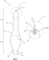
- an injection mold 10 defines a mold cavity 12.
- the mold cavity 12 has the inverse shape of a molded part (not shown), meaning that the surfaces of the mold cavity 12 give the molded part its shape.
- Molten material for forming the part is injected at an inlet 14 that is connected to a vertical passage or sprue 16. The molten material flows down the sprue 16, through a runner 18, and into the mold cavity 12 via a gate 20.
- the implementation illustrated in FIG. 1 has one mold cavity, one gate, one runner, and one sprue, some implementations may include multiple mold cavities and a corresponding network of sprues, runners, and gates.
- the injection mold may include an ejector assembly to help remove the molded part from the mold.
- An ejector assembly may include one or more knockout pins attached to an ejector plate and a motor that drives the ejector plate.
- An outer shaping surface 24 corresponds to the outer surface of the finished part.
- the outer shaping surface 24 is formed by first and second cavity plates 28, 30 and a first holder plate 32 that is described in more detail below.
- a single cavity plate may be sufficient to form the outer shaping surface 24, or more than two cavity plates may be necessary to form the outer shaping surface 24.
- the runner 18 and gate 20 are formed in second cavity plate 30, and the sprue 16 extends along both cavity plates 28, 30. The shape and placement of the sprue 16, the runner 18, and the gate 20 depends on the mold geometry and the properties of the molten material (e.g. viscosity) and may therefore be different than illustrated in FIG. 1 .
- An inner shaping surface 26 corresponds to the inner surface of the finished part.
- the inner shaping surface 26 is formed by a core 34.
- the core 34 includes a shaping section 36 ( FIG. 2 ) that is inserted into the space or void formed by the first and second cavity plates 28, 30.
- an outer surface 38 of the shaping section 36 is also the inner shaping surface 26 of the mold cavity 12.
- the core 34 is supported by the first holder plate 32 that also forms part of the outer shaping surface 24, a second holder plate 40, and a core clamp 42.
- the first and second holder plates 32, 40 and the core clamp 42 are described in more detail in reference to FIG. 2 .
- the injection mold 10 thus comprises a cavity section 44 and a core section 46 that meet along mold parting line 22 ( FIG. 3 ).
- the injection mold 10 may also include clamping or support plates that compress the mold parts together, an alignment mechanism that aligns the cavity section 44 and the core section 46, or both.
- FIG. 2 is an enlarged view of a core 34 that is similar to the core 34 shown in FIG. 1 .
- the core 34 includes a shaping section 36 and a supporting section 48.
- the shaping section 36 extends from a first end 50 of the core 34 and is arranged in the void formed by the first and second cavity plates 28, 30 of the cavity section 44.
- the outer surface 38 of the shaping section 36 forms the inner shaping surface 26 of the mold cavity 12 when the core 34 is installed in the core section 46 of the injection mold 10.
- the supporting section 48 maintains the position of the core 34 when the core 34 is installed in the core section 46 by engaging the first and second holder plates 32, 40 and the core clamp 42. In other words, the supporting section 48 does not directly form the mold cavity 12 and does not include a shaping or forming surface.
- the supporting section 48 extends from a second end 52, towards the shaping section 36 and the first end 50 of the core 34.
- the core 34 in FIG. 2 has multiple assembled parts, as shown in the enlarged partial cross section X of the tip 50. More specifically, the core 34 includes a body 54 and a removable pin 56 that are connected by a threaded connection 58.
- the removable pin 56 may be used to mold a small hole (e.g. diameter of less than or equal to 0.2 mm) in the finished part.
- the outer shaping surface 24 may have a small recess that mates with an end surface 60 of the pin 56. Due to its small diameter, the pin 56 is more prone to breakage than the body 54 of the core 34.
- the pin 56 can be made of a harder material than the body 54 or replaced when broken.
- the shaping section 36 and supporting section 48 may be formed by separate parts, since the shaping section 36 is more susceptible to wear than the supporting section 48.
- a dotted line 61 schematically indicates, for example, a screwed connection between the shaping and supporting sections 36, 48. The placement of the connection line 61 may not necessarily coincide with the transition between the shaping and supporting sections 36, 48, e.g., to avoid a visible line or break in the molded part.
- the clamping section 64 is located adjacent the second end 52 and engages the core clamp 42 shown in FIG. 1 .
- the clamping section 64 includes a peripherally extending groove 66 that receives a pair of jaws of the core clamp 42.
- the core 34 may include a pull stud bolt that is threaded into a hole in the body 54, similarly to the pull stud bolts used to connect milling cutters to CNC machines.
- the core clamp 42 may include a collet or a ball-type device to engage the enlarged head of the pull stud bolt.
- FIG. 3 an injection mold 10 similar to the example illustrated in FIG. 1 is shown in an open state.
- the cavity section 44 and the core section 46 are separated along the mold parting line 22 to expose the inner shaping surface 26, i.e. the surface 38 of the shaping section 36 of the core 34.
- the repetitive process of removing molded parts from the core 34 may cause scratches on the surface 38 that diminish the quality of the molded parts.
- the core 34 may also become cracked, or an additional part, such as the pin 56 (not shown), may break or be missing.
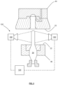
- a sensor system 100 is illustrated.
- the sensor system 100 includes one or more sensing devices 102 that are communicatively coupled to a controller 104.
- the sensing devices 102 are cameras trained on the outer surface 38 of the shaping section 36 of the core 34.
- the cameras are configured to send image data to the controller 104, and the controller 104 uses software to determine the presence of scratches, cracks, or missing parts.
- the cameras of the sensing system may be used to screen the molded parts for defects resulting from scratches, cracks, or missing parts.
- the camera may capture one or more images after every injection molding cycle. If the mold or molded parts passes the quality test (e.g. no scratches are detected), the controller 104 may determine that the core 34 is fit for use.
- the sensor system 100 may include a photoelectric sensor that senses the presence of a part such as the pin 56.
- a through-beam photoelectric sensor may be arranged so that the pin 56 is located within the line-of-sight of the receiver, blocking the light beam from reaching the receiver.
- the beam of light may extend from the transmitter to the receiver, sending a signal to the controller 104.
- the sensing devices 102 may include proximity sensors.
- the proximity sensors may be optical proximity sensors that detect the presence or absence of the pin 56.
- the proximity sensors may also use inductance or capacitance to detect the presence or absence of the pin 56, based on the material of the pin (e.g. metal).
- the sensor system 100 may also include a combination of different sensing devices.
- a camera may be used to check for scratches, while an induction or capacitive proximity sensor detects the presence of the pin 56.
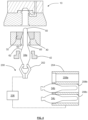
- an automated core changer system 200 includes a mover 202, a rack 204, and a controller 206.
- the mover 202 is schematically illustrated as a pair of jaws that grip the clamping section 64 of the core 34, for example, the peripheral groove 66.
- the controller 206 may send signal to the mover 202 to begin the core change operation.
- the controller 206 is illustrated separately from the controller 104 of the sensor system 100, they may also be one and the same, i.e. the sensor system 100 is optionally incorporated into the core changer system 200.
- the controller 206 may be a standalone device that is separate from the control system (not shown) for the injection molding machine, making it possible to retrofit the core changer system 200 to an existing injection molding machine. However, it is also conceivable that the injection molding machine's control system also implements the control operations for the core changer system 200, the sensor system 100, or both.
- the controller 206 may then control the mover 202 to engage the clamping section 64 of the core 34 installed in the core section 46 of the injection mold 10.
- the mover 202 then loosens the installed core 34 by an appropriate movement, e.g., gently twisting or pulling the core away from the core section 46.
- the mover 202 moves the used core to the rack 204.
- the rack 204 has a plurality of slots 208a-208c that each hold a core 34a-34c.
- the cores 34a-34c are shown to be identical, the rack 204 may hold differently shaped cores, and the core changer system 200 is used to automatically change the cores and thus the shape of the mold cavities.
- the mover 202 After depositing the used core in an appropriate slot 208, the mover 202 then moves to a different slot 208 to retrieve an undamaged core 34.
- the controller 206 may be communicatively coupled to the rack 204.
- the mover 202 may communicate the positions of the damaged and undamaged cores to the controller 206 without the rack 204 being communicatively coupled to the controller 206.
- the mover 202 guides the tip 50 of the core through a passage formed by the conical surface 63 in the first holder plate 32 and a cylindrical opening 65 in the second holder plate 40. Once the conical centering surface 62 of the core 34 and the surface 63 of the first holder plate 32 engage, the core 34 and the first holder plate 32 are centered. At this point, the jaws of the mover 202 may release the core's clamping section 64, and the core clamp 42 engages the clamping section 64 to keep the core 34 in place. As described, the mover 202 forms an automated core changing tool.
- the controller 206 may send a signal to a controller of an injection molding machine (not shown) that the injection mold 10 is ready for use.
- the core changer system 200 can be used with any type of core that has a clamping section that can be gripped by the mover 202.
- the mover 202 may include a magnet or vacuum suction device that engages the clamping section of a core.
- the mover 202 and the core clamp 42 are illustrated as separate parts in FIG. 4 , in some implementations, the core clamp 42 may also form the mover 202 for the core changer system 200.
- the described core changer system may automatically switch the core in an injection mold and automatically render it fit for use.
- the core may be switched after a predetermined number of injection mold cycles.
- the controller of an injection molding machine may send a signal (e.g. a core change signal) to the controller 206 to instigate the core switching process.
- the core may be switched in response to a signal provided by the controller 104 of the sensor system 100. In both implementations, the core switching process may minimize defects in subsequent molded parts by providing a new and intact core in the injection mold.
- the core switching process may be instigated based on the number of production cycles and in response to input from the sensor system. Some implementations may be configured to generally instigate the core switching process after a particular number of molding cycles. Once the pre-determined number of cycles has been reached, sensor input may be used to determine whether to trigger a core change. For example, if a camera continues to capture image data of a scratch-free or intact core, the system may be configured to postpone the core switching process.
- a schematic overview of a method 300 of automatically changing an injection mold core in an injection molding machine is shown.
- a core is disconnected from an injection mold using a gripper in response to a core change signal and depositing the disconnected core.
- a replacement core is retrieved, also using the gripper.
- the replacement core may have the same structure as the core that was disconnected from the injection mold.
- the gripper is used to connect the replacement core to the injection mold.
- an enable signal is sent to a controller of the injection molding machine. The enable signal communicates to the controller of the injection molding machine that the mold core has been replaced and the injection molding process can restart.
- the core change signal may originate from different sources.
- the core change signal may be received from the controller of the injection molding machine based on a number of molding cycles.
- Some implementations of the method use a sensing device to detect whether the core connected to the injection mold is intact (e.g. whether part of the core is missing), and the core change signal is based on this detection.
- a different sensing device may be used to detect scratches, dents, or cracks, and the core change signal is based on the detection of the core's scratches, dents, or cracks.
- a sensing device may be used to quality test for scratches or defects on the parts molded by the injection mold, and the core change signal may be based on this quality control of the molded parts.
- the method may include multiple forms of quality control that are performed after every molding cycle, and the core change signal may be obtained based on the combined input of the multiple sensing devices.
- a first sensing device may sense an irregularity on a part of a mold core
- a second sensing device may show that the irregularity does not have an impact on the molded parts.
- the input of the second sensing device may be used to override the first sensing device to avoid a premature core switching operation.
- one input may override the other input and instigate a core changing operation.
- the number of injection molding cycles may be below a predetermined threshold that triggers a core change signal, but input from a sensing device that detects a defect on the molded part may nonetheless trigger the core change signal.
Landscapes
- Engineering & Computer Science (AREA)
- Mechanical Engineering (AREA)
- Manufacturing & Machinery (AREA)
- Moulds For Moulding Plastics Or The Like (AREA)
- Injection Moulding Of Plastics Or The Like (AREA)
Claims (17)
- Système (200) destiné à un moule d'injection (10) comprenant :un organe de préhension (202) ;un support (204) qui comprend une pluralité de fentes (208a à 208c), chacune conçue pour tenir un noyau de moule (34, 34a à c) ;un dispositif (206) configuré pour commander l'organe de préhension (202) en réponse à la réception d'un signal de changement de noyau pourdésassembler un noyau (34a) du moule d'injection (10), déposer le noyau (34a) désassemblé dans une fente de la pluralité de fentes (208a à 208c) du support (204),récupérer un noyau (34b, 34c) stocké dans une fente différente de la pluralité de fentes (208a à 208c) du support (204), etrelier le noyau (34b, 34c) au moule d'injection (10), caractérisé parun dispositif de détection (102) configuré pour détecter une propriété du noyau de moule (34, 34a à c) assemblé dans le moule d'injection (10), dans lequel le signal de changement de noyau est généré en réponse à un signal de capteur.
- Système (200) selon la revendication 1, dans lequel le dispositif de commande (206) est configuré pour recevoir le signal de changement de noyau provenant d'une machine de moulage par injection comprenant le moule d'injection (10), dans lequel le signal de changement de noyau est généré sur la base d'un nombre de cycles d'injection de la machine de moulage par injection.
- Système (200) selon la revendication 1, dans lequel le dispositif de détection (102) comprend un ou plusieurs appareils de prise de vues configurés pour détecter des rayures ou des défauts sur une surface du noyau de moule (34, 34a à c).
- Système (200) selon la revendication 1, dans lequel le dispositif de détection (102) est configuré pour détecter la présence d'au moins une partie du noyau de moule (34, 34a à c) sur la base d'une inductance ou d'une capacité.
- Système (200) selon la revendication 1, dans lequel le dispositif de détection (102) comprend un dispositif optoélectronique configuré pour détecter la présence d'au moins une partie du noyau de moule (34, 34a à c).
- Système (200) selon l'une quelconque des revendications 1 et 3 à 5, dans lequel le dispositif de détection (102) comprend un ou plusieurs appareils de prise de vues configurés pour détecter des rayures ou des défauts sur une surface d'une ou plusieurs pièces moulées par le moule d'injection (10).
- Combinaison comprenant le moule d'injection (10) et le système (200) selon l'une quelconque des revendications 1 à 6, dans laquelle le moule d'injection (10) comprend :une surface de façonnage externe (24) et une surface de façonnage interne (26) qui coopèrent pour délimiter une cavité de moule (12) ;un corps de moule qui comprend la surface de façonnage externe (24) ; etun noyau mobile (34, 34a à c) qui comprend la surface de façonnage interne (26), le noyau (34, 34a à c) étant conçu pour être saisi par un outil de changement de noyau automatisé.
- Combinaison selon la revendication 7, dans laquelle le noyau (34, 34a à c) comprend une section de serrage (64) conçue pour être saisie par l'outil de changement de noyau automatisé et conçue pour entrer en prise avec un élément de fixation qui fixe le noyau (34) au corps de moule.
- Combinaison selon la revendication 8, dans laquelle la section de serrage (64) comprend une rainure (66) ou un évidement.
- Combinaison selon l'une quelconque des revendications 7 à 9, dans laquelle le noyau (34, 34a à c) et le corps de moule sont conçus pour coopérer et centrer le noyau (34, 34a à c) par rapport au corps de moule.
- Combinaison selon l'une quelconque des revendications 7 à 10, dans laquelle le noyau (34, 34a à c) comprend une pluralité de parties assemblées.
- Combinaison selon la revendication 11, dans laquelle le noyau (34, 34a à c) comprend une section de façonnage (36) qui comprend la surface de façonnage interne (26) et une section de support détachable (48) qui relie le corps (54) du noyau (34, 34a à c) au corps de moule.
- Procédé (300) comprenant :le détachement, à l'aide d'un organe de préhension, d'un noyau (34a) à partir d'un moule d'injection (10) en réponse à un signal de changement de noyau et le dépôt du noyau (34a) détaché ;la récupération, à l'aide de l'organe de préhension, d'un noyau de remplacement (34b, 34c) ;la liaison, à l'aide de l'organe de préhension, du noyau de remplacement (34b, 34c) au moule d'injection (10) ;l'envoi d'un signal d'activation à un dispositif de commande (104, 206) d'une machine de moulage par injection qui comprend le moule d'injection (10) ; caractérisé parla détection, à l'aide d'un dispositif de détection (102), établissant si le noyau (34, 34a à c) relié au moule d'injection (10) est intact ; etla réception du signal de changement de noyau provenant du dispositif de détection (102).
- Procédé selon la revendication 13, comprenant en outre la réception du signal de changement de noyau provenant du dispositif de commande (104, 206) de la machine de moulage par injection sur la base d'un nombre de cycles de moulage.
- Procédé selon la revendication 13 ou 14, comprenant en outrela détection, à l'aide d'un dispositif de détection (102), de rayures ou défauts sur le noyau (34, 34a à c) etla réception du signal de changement de noyau provenant du dispositif de détection (102).
- Procédé selon l'une quelconque des revendications 13 à 15, comprenant en outrele moulage, à l'aide du moule d'injection (10), d'une ou plusieurs pièces ;la détection, à l'aide d'un dispositif de détection, de rayures ou défauts sur les pièces moulées ; etla réception du signal de changement de noyau provenant du dispositif de détection.
- Procédé selon l'une quelconque des revendications 13 à 15, dans lequel la récupération d'un noyau de remplacement (34, 34a à c) comprend la récupération d'un noyau de remplacement (34, 34a à c) qui a la même structure que le noyau (34, 34a à c) désassemblé.
Priority Applications (5)
| Application Number | Priority Date | Filing Date | Title |
|---|---|---|---|
| ES20197185T ES3040105T3 (en) | 2020-09-21 | 2020-09-21 | Maintaining injection molding tools |
| PL20197185.0T PL3970943T3 (pl) | 2020-09-21 | 2020-09-21 | Konserwacja narzędzi do formowania wtryskowego |
| PT201971850T PT3970943T (pt) | 2020-09-21 | 2020-09-21 | Manutenção de ferramentas de moldagem por injeção |
| EP20197185.0A EP3970943B1 (fr) | 2020-09-21 | 2020-09-21 | Entretien d'outils de moulage par injection |
| DK20197185.0T DK3970943T3 (da) | 2020-09-21 | 2020-09-21 | Vedligeholdelse af sprøjtestøbningsværktøj |
Applications Claiming Priority (1)
| Application Number | Priority Date | Filing Date | Title |
|---|---|---|---|
| EP20197185.0A EP3970943B1 (fr) | 2020-09-21 | 2020-09-21 | Entretien d'outils de moulage par injection |
Publications (2)
| Publication Number | Publication Date |
|---|---|
| EP3970943A1 EP3970943A1 (fr) | 2022-03-23 |
| EP3970943B1 true EP3970943B1 (fr) | 2025-06-04 |
Family
ID=72603416
Family Applications (1)
| Application Number | Title | Priority Date | Filing Date |
|---|---|---|---|
| EP20197185.0A Active EP3970943B1 (fr) | 2020-09-21 | 2020-09-21 | Entretien d'outils de moulage par injection |
Country Status (5)
| Country | Link |
|---|---|
| EP (1) | EP3970943B1 (fr) |
| DK (1) | DK3970943T3 (fr) |
| ES (1) | ES3040105T3 (fr) |
| PL (1) | PL3970943T3 (fr) |
| PT (1) | PT3970943T (fr) |
Family Cites Families (4)
| Publication number | Priority date | Publication date | Assignee | Title |
|---|---|---|---|---|
| JP3366111B2 (ja) * | 1994-05-11 | 2003-01-14 | アマノ株式会社 | 射出成形機用金型自動交換装置 |
| EP2418068B1 (fr) * | 2010-08-10 | 2016-11-09 | Mold-Masters (2007) Limited | Système de moulage à changement rapide pour moulage par injection |
| JP2016168732A (ja) * | 2015-03-12 | 2016-09-23 | ファナック株式会社 | 金型清掃を行う射出成形システム |
| JP6434441B2 (ja) * | 2016-04-07 | 2018-12-05 | ファナック株式会社 | 成形システム |
-
2020
- 2020-09-21 PT PT201971850T patent/PT3970943T/pt unknown
- 2020-09-21 DK DK20197185.0T patent/DK3970943T3/da active
- 2020-09-21 ES ES20197185T patent/ES3040105T3/es active Active
- 2020-09-21 EP EP20197185.0A patent/EP3970943B1/fr active Active
- 2020-09-21 PL PL20197185.0T patent/PL3970943T3/pl unknown
Also Published As
| Publication number | Publication date |
|---|---|
| EP3970943A1 (fr) | 2022-03-23 |
| DK3970943T3 (da) | 2025-08-25 |
| PT3970943T (pt) | 2025-08-05 |
| PL3970943T3 (pl) | 2025-10-20 |
| ES3040105T3 (en) | 2025-10-29 |
Similar Documents
| Publication | Publication Date | Title |
|---|---|---|
| EP3520983B1 (fr) | Procédé de moulage par injection et unité de moulage | |
| KR102191379B1 (ko) | 로봇을 이용한 터미널 자동 인서트 시스템 | |
| EP3970943B1 (fr) | Entretien d'outils de moulage par injection | |
| JP6426651B2 (ja) | 金型内にて組立作業を行う射出成形システム | |
| CN101823317A (zh) | 可自动切断浇口的机动塑压模具 | |
| EP3747617B1 (fr) | Machine et système de moulage par injection | |
| KR20160143401A (ko) | 3단 사출금형 및 3단 사출금형의 제품취출방법 | |
| EP3520984B1 (fr) | Procédé de moulage par injection et unité de moulage | |
| KR101874916B1 (ko) | 사출물 제조장치 | |
| CN101304861A (zh) | 模制物件操纵装置 | |
| CN220636192U (zh) | 一种便于脱模的法兰预锻模 | |
| CN113442398A (zh) | 成型品检查装置及注射成型系统 | |
| JP2010099914A (ja) | インモールドラベリング容器の製造装置 | |
| JP2012086492A (ja) | 成形機の金型位置決め装置 | |
| JP3784980B2 (ja) | 射出成形機の金型機構部における割型の型開閉順序監視方法とその装置 | |
| CN220331897U (zh) | 一种新型塑料注塑模具开模机构 | |
| CN215039654U (zh) | 一种铁片拉料裁切机构 | |
| CN210415312U (zh) | 一种复合抽芯脱螺纹机构 | |
| JP4915299B2 (ja) | 成形方法 | |
| CN219820541U (zh) | 一种旋转取件治具 | |
| CN119116258B (zh) | 注塑预埋装入机构及注塑方法 | |
| CN217553057U (zh) | 一种镶嵌视觉检测取件器 | |
| CN112676380B (zh) | 压力机工件温度精确检测装置及检测方法 | |
| JP6124763B2 (ja) | 樹脂封止装置 | |
| CN219075708U (zh) | 一种硅胶奶嘴自动取出机械手 |
Legal Events
| Date | Code | Title | Description |
|---|---|---|---|
| PUAI | Public reference made under article 153(3) epc to a published international application that has entered the european phase |
Free format text: ORIGINAL CODE: 0009012 |
|
| STAA | Information on the status of an ep patent application or granted ep patent |
Free format text: STATUS: REQUEST FOR EXAMINATION WAS MADE |
|
| 17P | Request for examination filed |
Effective date: 20200921 |
|
| AK | Designated contracting states |
Kind code of ref document: A1 Designated state(s): AL AT BE BG CH CY CZ DE DK EE ES FI FR GB GR HR HU IE IS IT LI LT LU LV MC MK MT NL NO PL PT RO RS SE SI SK SM TR |
|
| GRAP | Despatch of communication of intention to grant a patent |
Free format text: ORIGINAL CODE: EPIDOSNIGR1 |
|
| STAA | Information on the status of an ep patent application or granted ep patent |
Free format text: STATUS: GRANT OF PATENT IS INTENDED |
|
| RIC1 | Information provided on ipc code assigned before grant |
Ipc: B29C 33/70 20060101ALN20241219BHEP Ipc: B29C 45/26 20060101ALN20241219BHEP Ipc: B29K 105/00 20060101ALN20241219BHEP Ipc: B29C 45/36 20060101ALN20241219BHEP Ipc: B29C 45/76 20060101ALN20241219BHEP Ipc: B29C 45/17 20060101AFI20241219BHEP |
|
| INTG | Intention to grant announced |
Effective date: 20250108 |
|
| GRAS | Grant fee paid |
Free format text: ORIGINAL CODE: EPIDOSNIGR3 |
|
| GRAA | (expected) grant |
Free format text: ORIGINAL CODE: 0009210 |
|
| STAA | Information on the status of an ep patent application or granted ep patent |
Free format text: STATUS: THE PATENT HAS BEEN GRANTED |
|
| AK | Designated contracting states |
Kind code of ref document: B1 Designated state(s): AL AT BE BG CH CY CZ DE DK EE ES FI FR GB GR HR HU IE IS IT LI LT LU LV MC MK MT NL NO PL PT RO RS SE SI SK SM TR |
|
| REG | Reference to a national code |
Ref country code: GB Ref legal event code: FG4D |
|
| REG | Reference to a national code |
Ref country code: CH Ref legal event code: EP |
|
| REG | Reference to a national code |
Ref country code: DE Ref legal event code: R096 Ref document number: 602020052208 Country of ref document: DE |
|
| REG | Reference to a national code |
Ref country code: IE Ref legal event code: FG4D |
|
| P01 | Opt-out of the competence of the unified patent court (upc) registered |
Free format text: CASE NUMBER: APP_26546/2025 Effective date: 20250604 |
|
| REG | Reference to a national code |
Ref country code: PT Ref legal event code: SC4A Ref document number: 3970943 Country of ref document: PT Date of ref document: 20250805 Kind code of ref document: T Free format text: AVAILABILITY OF NATIONAL TRANSLATION Effective date: 20250729 |
|
| REG | Reference to a national code |
Ref country code: DK Ref legal event code: T3 Effective date: 20250822 |
|
| REG | Reference to a national code |
Ref country code: NL Ref legal event code: FP |
|
| PG25 | Lapsed in a contracting state [announced via postgrant information from national office to epo] |
Ref country code: FI Free format text: LAPSE BECAUSE OF FAILURE TO SUBMIT A TRANSLATION OF THE DESCRIPTION OR TO PAY THE FEE WITHIN THE PRESCRIBED TIME-LIMIT Effective date: 20250604 |
|
| PGFP | Annual fee paid to national office [announced via postgrant information from national office to epo] |
Ref country code: PT Payment date: 20250905 Year of fee payment: 6 |
|
| PGFP | Annual fee paid to national office [announced via postgrant information from national office to epo] |
Ref country code: DE Payment date: 20250919 Year of fee payment: 6 Ref country code: DK Payment date: 20250922 Year of fee payment: 6 |
|
| REG | Reference to a national code |
Ref country code: LT Ref legal event code: MG9D |
|
| PG25 | Lapsed in a contracting state [announced via postgrant information from national office to epo] |
Ref country code: GR Free format text: LAPSE BECAUSE OF FAILURE TO SUBMIT A TRANSLATION OF THE DESCRIPTION OR TO PAY THE FEE WITHIN THE PRESCRIBED TIME-LIMIT Effective date: 20250905 Ref country code: NO Free format text: LAPSE BECAUSE OF FAILURE TO SUBMIT A TRANSLATION OF THE DESCRIPTION OR TO PAY THE FEE WITHIN THE PRESCRIBED TIME-LIMIT Effective date: 20250904 |
|
| PGFP | Annual fee paid to national office [announced via postgrant information from national office to epo] |
Ref country code: IT Payment date: 20250926 Year of fee payment: 6 Ref country code: NL Payment date: 20250922 Year of fee payment: 6 |
|
| PG25 | Lapsed in a contracting state [announced via postgrant information from national office to epo] |
Ref country code: BG Free format text: LAPSE BECAUSE OF FAILURE TO SUBMIT A TRANSLATION OF THE DESCRIPTION OR TO PAY THE FEE WITHIN THE PRESCRIBED TIME-LIMIT Effective date: 20250604 |
|
| PG25 | Lapsed in a contracting state [announced via postgrant information from national office to epo] |
Ref country code: HR Free format text: LAPSE BECAUSE OF FAILURE TO SUBMIT A TRANSLATION OF THE DESCRIPTION OR TO PAY THE FEE WITHIN THE PRESCRIBED TIME-LIMIT Effective date: 20250604 |
|
| PGFP | Annual fee paid to national office [announced via postgrant information from national office to epo] |
Ref country code: FR Payment date: 20250922 Year of fee payment: 6 Ref country code: AT Payment date: 20250918 Year of fee payment: 6 |
|
| PG25 | Lapsed in a contracting state [announced via postgrant information from national office to epo] |
Ref country code: RS Free format text: LAPSE BECAUSE OF FAILURE TO SUBMIT A TRANSLATION OF THE DESCRIPTION OR TO PAY THE FEE WITHIN THE PRESCRIBED TIME-LIMIT Effective date: 20250904 |
|
| PGFP | Annual fee paid to national office [announced via postgrant information from national office to epo] |
Ref country code: CZ Payment date: 20250905 Year of fee payment: 6 |
|
| PG25 | Lapsed in a contracting state [announced via postgrant information from national office to epo] |
Ref country code: LV Free format text: LAPSE BECAUSE OF FAILURE TO SUBMIT A TRANSLATION OF THE DESCRIPTION OR TO PAY THE FEE WITHIN THE PRESCRIBED TIME-LIMIT Effective date: 20250604 |
|
| REG | Reference to a national code |
Ref country code: ES Ref legal event code: FG2A Ref document number: 3040105 Country of ref document: ES Kind code of ref document: T3 Effective date: 20251029 |
|
| PGFP | Annual fee paid to national office [announced via postgrant information from national office to epo] |
Ref country code: MK Payment date: 20250905 Year of fee payment: 6 |
|
| PG25 | Lapsed in a contracting state [announced via postgrant information from national office to epo] |
Ref country code: IS Free format text: LAPSE BECAUSE OF FAILURE TO SUBMIT A TRANSLATION OF THE DESCRIPTION OR TO PAY THE FEE WITHIN THE PRESCRIBED TIME-LIMIT Effective date: 20251004 |
|
| PG25 | Lapsed in a contracting state [announced via postgrant information from national office to epo] |
Ref country code: SM Free format text: LAPSE BECAUSE OF FAILURE TO SUBMIT A TRANSLATION OF THE DESCRIPTION OR TO PAY THE FEE WITHIN THE PRESCRIBED TIME-LIMIT Effective date: 20250604 |
|
| PGFP | Annual fee paid to national office [announced via postgrant information from national office to epo] |
Ref country code: PL Payment date: 20250909 Year of fee payment: 6 |
|
| PG25 | Lapsed in a contracting state [announced via postgrant information from national office to epo] |
Ref country code: EE Free format text: LAPSE BECAUSE OF FAILURE TO SUBMIT A TRANSLATION OF THE DESCRIPTION OR TO PAY THE FEE WITHIN THE PRESCRIBED TIME-LIMIT Effective date: 20250604 |
|
| PG25 | Lapsed in a contracting state [announced via postgrant information from national office to epo] |
Ref country code: SK Free format text: LAPSE BECAUSE OF FAILURE TO SUBMIT A TRANSLATION OF THE DESCRIPTION OR TO PAY THE FEE WITHIN THE PRESCRIBED TIME-LIMIT Effective date: 20250604 Ref country code: RO Free format text: LAPSE BECAUSE OF FAILURE TO SUBMIT A TRANSLATION OF THE DESCRIPTION OR TO PAY THE FEE WITHIN THE PRESCRIBED TIME-LIMIT Effective date: 20250604 |
|
| PGFP | Annual fee paid to national office [announced via postgrant information from national office to epo] |
Ref country code: ES Payment date: 20251020 Year of fee payment: 6 |
|
| REG | Reference to a national code |
Ref country code: DE Ref legal event code: R097 Ref document number: 602020052208 Country of ref document: DE |
|
| PLBE | No opposition filed within time limit |
Free format text: ORIGINAL CODE: 0009261 |
|
| STAA | Information on the status of an ep patent application or granted ep patent |
Free format text: STATUS: NO OPPOSITION FILED WITHIN TIME LIMIT |
|
| REG | Reference to a national code |
Ref country code: CH Ref legal event code: L10 Free format text: ST27 STATUS EVENT CODE: U-0-0-L10-L00 (AS PROVIDED BY THE NATIONAL OFFICE) Effective date: 20260416 |