EP3964657B1 - Véhicule de nettoyage de canal - Google Patents
Véhicule de nettoyage de canal Download PDFInfo
- Publication number
- EP3964657B1 EP3964657B1 EP20194995.5A EP20194995A EP3964657B1 EP 3964657 B1 EP3964657 B1 EP 3964657B1 EP 20194995 A EP20194995 A EP 20194995A EP 3964657 B1 EP3964657 B1 EP 3964657B1
- Authority
- EP
- European Patent Office
- Prior art keywords
- telescopic boom
- roller
- pressure hose
- hose
- support rollers
- Prior art date
- Legal status (The legal status is an assumption and is not a legal conclusion. Google has not performed a legal analysis and makes no representation as to the accuracy of the status listed.)
- Active
Links
- 238000004140 cleaning Methods 0.000 title description 15
- 239000010802 sludge Substances 0.000 claims description 8
- 239000000356 contaminant Substances 0.000 claims description 2
- 239000002351 wastewater Substances 0.000 claims 2
- XLYOFNOQVPJJNP-UHFFFAOYSA-N water Substances O XLYOFNOQVPJJNP-UHFFFAOYSA-N 0.000 description 4
- 238000000034 method Methods 0.000 description 2
- 230000008878 coupling Effects 0.000 description 1
- 238000010168 coupling process Methods 0.000 description 1
- 238000005859 coupling reaction Methods 0.000 description 1
- 238000011161 development Methods 0.000 description 1
- 230000018109 developmental process Effects 0.000 description 1
- 239000012535 impurity Substances 0.000 description 1
- 230000009191 jumping Effects 0.000 description 1
- 239000007788 liquid Substances 0.000 description 1
- 230000007704 transition Effects 0.000 description 1
Images


Classifications
-
- E—FIXED CONSTRUCTIONS
- E03—WATER SUPPLY; SEWERAGE
- E03F—SEWERS; CESSPOOLS
- E03F7/00—Other installations or implements for operating sewer systems, e.g. for preventing or indicating stoppage; Emptying cesspools
- E03F7/10—Wheeled apparatus for emptying sewers or cesspools
- E03F7/106—Accessories, e.g. hose support
-
- E—FIXED CONSTRUCTIONS
- E03—WATER SUPPLY; SEWERAGE
- E03F—SEWERS; CESSPOOLS
- E03F7/00—Other installations or implements for operating sewer systems, e.g. for preventing or indicating stoppage; Emptying cesspools
- E03F7/10—Wheeled apparatus for emptying sewers or cesspools
Definitions
- the invention relates to a vehicle for loosening and sucking off impurities from sewers and sludge pits.
- Such vehicles are generally referred to as sewer cleaning vehicles.
- a high-pressure hose and a suction hose are inserted into the canal. Water is pumped into the canal through the high-pressure hose; this water is also used to propel the high-pressure hose into the canal.
- the high-pressure hose By pulling the high-pressure hose backwards through the channel, the water escaping backwards through a nozzle of the high-pressure hose can clean dirt adhering to the channel wall.
- the accumulated sludge components are then sucked through the suction hose into a storage tank of the sewer cleaning vehicle.
- a sewer cleaning vehicle in which the telescopic boom with suction hose and high-pressure hose should be pivotable by at least 360 degrees, resulting in an annular working area around the sewer cleaning vehicle.
- the high-pressure hose is looped around a pivot bearing located on the vehicle, overlapping at least a little. This leads to increased friction, which restricts the propulsion and mobility of the high-pressure hose.
- the DE 20 2016 002 943 U1 discloses a sewer cleaning vehicle with a pivotable telescopic boom, in which the high-pressure hose and the suction hose are guided together.
- the high pressure hose is mounted on a hose reel so that it can be wound up and unwound and is guided out of the vehicle approximately parallel to the longitudinal axis of the vehicle and into the telescopic boom.
- the telescopic boom is rotatably mounted on a horizontally arranged rotary bearing. This rotary bearing has a storage unit for the suction hose in the form of a hose reel.
- the rotary bearing also has rollers for the high-pressure hose, which are arranged in a circle around the axis of the rotary bearing and are present below the hose reel for the suction hose.
- the high-pressure hose In a first position of the telescopic boom, the high-pressure hose is at least partially in contact with the roller bodies of the rotary bearing, while in a second position of the telescopic boom, the high-pressure hose is guided directly from the hose reel into the telescopic boom without touching the roller bodies of the rotary bearing. In this way, a working range of around 320 degrees can be covered by the telescopic boom.
- the invention is based on the object of specifying an improved sewer cleaning vehicle that enables the high-pressure hose to be guided as securely as possible.
- the vehicle according to the invention for loosening and sucking up contaminants from sewers and sludge pits has a pivotable telescopic boom which can be positioned over the opening of the sewer or sludge pit.
- a high-pressure hose can be wound and unwound on a hose reel.
- the high-pressure hose can be approximately parallel to the longitudinal axis of the vehicle out of the vehicle and into the telescopic boom.
- a suction hose is stored in a storage device on the vehicle so that it can be pulled in and out.
- the high-pressure hose and the suction hose are routed together in the telescopic boom.
- the telescopic boom is rotatably mounted on a horizontally arranged rotary bearing. This pivot bearing has roller bodies for the high-pressure hose.
- roller bodies are arranged in a circle around the axis of the pivot bearing.
- the pivot bearing has support rollers for the high-pressure hose, which are arranged around the axis of the pivot bearing.
- the support rollers can be moved in such a way that in a first position they are approximately at the level of the roller bodies, so that the high-pressure hose is guided between the roller bodies and the support rollers.
- the support rollers are present above or below the level of the roller bodies.
- a working area of approximately 320 degrees can be covered by the telescopic boom.
- the working area can cover both the area directly behind and the area directly in front of the vehicle. Only on the side of the vehicle is there an area that cannot be covered by the telescopic boom.
- the sewer cleaning vehicle In order to be able to clean sewers and sludge pits in this area as well, the sewer cleaning vehicle only has to move back or forward a little. A cumbersome maneuvering of the sewer cleaning vehicle is not necessary.
- the high-pressure hose can be prevented from slipping or jumping out of its roller track in the pivot bearing. This enables safe operation of the vehicle according to the invention even with extreme deflections of the telescopic boom.
- the support rollers can be distributed over the entire pivot bearing and thus cover an angular range of 360 degrees.
- the high-pressure hose is only in contact with the roller bodies of the pivot bearing in an area of less than 180 degrees, it may be sufficient to provide the support rollers only in this area of the pivot bearing and thus in an angular range of about 180 degrees. It has been found to be sufficient to provide the support rollers at a distance of about 30 to 45 degrees from one another, so that a total of five support rollers are sufficient.
- the process of the support rollers from their first to their second position and vice versa can preferably be done via a link guide.
- Link guides are easy to implement in terms of design and are generally not very prone to failure.
- the link guide can have a turntable which is attached to the pivot bearing and can be rotated about the axis of the pivot bearing.
- the link guide can have a stationary guide rail that is present below or above the turntable.
- the support rollers can be mounted on the turntable so that they can be moved along the stationary guide rail and are vertically displaceable.
- the stationary guide rail can be circular and have a first section and a second section. The distance between the stationary guide rail and the turntable can be smaller in the area of the first section than in the area of the second section.
- the support rollers are therefore located in the area of the first section of the guide rail, they are aligned approximately at the same height as the roller bodies of the pivot bearing. If, on the other hand, the support rollers are in the area of the second track section, the support rollers have been moved downwards or upwards and therefore release the area of the rotary bearing to the outside.
- the second section can therefore, in particular, in Be arranged in the pivot bearing area of the inlet of the high-pressure hose.
- the stationary guide rail can preferably be arranged below the turntable.
- the support rollers can each have at least one driving roller, through which the support rollers can be moved on the stationary guide rail.
- support sleeves can be attached to the turntable, in which the support rollers are mounted so that they can be displaced longitudinally.
- the high-pressure hose and the suction hose can be guided within the telescopic boom, at least in some areas, on roller bodies. At least some of these roller bodies can be designed to be motor-driven.
- the pivot bearing of the telescopic boom can have a storage unit for the suction hose.
- This storage unit can preferably be designed as a hose reel.
- the roller bodies for the high-pressure hose can be present in particular below the storage unit of the suction hose.
- the telescopic jib can have a jib arm that is preferably designed to be telescopic, and a guide element is integrally formed on the vehicle-side end of the jib arm.
- This guide element can then be rotatably mounted on the pivot bearing.
- the cantilever arm and the guide element can form an angle of approximately 100 to 110 degrees, so that the telescopic boom is designed in a quasi-kinked manner.
- the boom arm of the telescopic boom can be designed to be telescopic once or multiple times.
- This angled design makes it possible to further increase the working area of the sewer cleaning vehicle.
- the telescopic boom in this case is not in the field of vision of the driver when the cantilever arm is aligned forward parallel to the longitudinal direction of the vehicle. In principle, it would therefore be possible to move the vehicle even if the telescopic boom is in front of the driver's cab. This would make the work of the driver of a vehicle according to the invention much easier and can also ensure that the travel times of the vehicle between two cleaning processes can be significantly reduced.
- the high-pressure hose can be guided into the telescopic boom via at least one pair of rollers. If two pairs of rollers are to be present, they can form a funnel-shaped inlet for the high-pressure hose.
- the high-pressure hose runs between the two rollers of the at least one pair of rollers.
- the at least one pair of rollers is arranged in one plane with the roller bodies of the pivot bearing. If the telescopic boom is positioned to the side of the vehicle on the side of the hose reel for the high-pressure hose, the high-pressure hose can rest on the outer roller of the pair of rollers and be guided directly from the hose reel into the telescopic boom.
- the high-pressure hose can lie against the inner roller of the pair of rollers and be transferred from this roller to the roller body of the rotary bearing. In this position of the telescopic boom, the high-pressure hose runs at least in sections around the rotary bearing.
- the at least one pair of rollers of the telescopic boom can preferably be arranged in the transition area between the boom arm and the guide element and thus in the area of the bend in the telescopic boom. In this way, the high-pressure hose can be inserted directly into the boom arm of the telescopic boom, which further increases the working range of the vehicle.
- the roller guide can be mounted to be longitudinally displaceable along the longitudinal axis of the vehicle. Such a shift would lead the high-pressure hose from the hose reel directly into the telescopic boom without touching the roller body of the rotary bearing.
- the roller guide can preferably be displaced by the telescopic boom in the direction of the hose reel for the high-pressure hose, so that there is free space for further pivoting of the telescopic boom.
- the roller guide can have a stop roller, through which the roller guide can be displaced through the telescopic boom.
- the roller guide can be returned to its starting position, preferably by a restoring force.
- This restoring force can in particular be a tension gas spring, a gas pressure spring or a pneumatic cylinder.
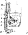
- a sewer cleaning vehicle 10 has a chassis adapted to its maximum load.
- a tank is located behind the driver's cab 12 of the vehicle 10 in a manner known per se.
- the tank serves as a storage device to store extracted sludge.
- other tanks or other containers could also be provided, for example to keep a supply of cleaning liquid.
- a rotary bearing 20 is present above the tank.
- a storage unit in the form of a hose reel 22 is rotatably fastened to the rotary bearing 20 .
- a suction hose 24 is at least partially wound up on the hose reel 22 .
- the hose reel 22 is rotatably mounted about the axis 26 of the pivot bearing 20 so that the suction hose 24 can be wound onto the hose reel 22 or unwound from it.
- the suction hose 24 is connected to the tank in which the dirty water sucked in through the suction hose 24 is to be stored.
- a telescopic boom 30 is also arranged above the tank.
- the telescopic boom 30 is in the present example mounted below the hose reel 22 on the pivot bearing 20 and can also be pivoted about the axis 26.
- Hose reel 22 and telescopic boom 30 can be coupled to one another in such a way that when hose reel 22 rotates about axis 26 , telescopic boom 30 is also pivoted about axis 26 .
- the telescopic boom 30 has a telescopically designed boom arm 32 which is integrally formed on a guide element 34 at its vehicle-side end. Boom arm 32 and guide element 34 are arranged at an angle to one another, so that telescopic boom 30 has a kink 36 (see in particular 9 ).
- the cantilever arm 32 is thus off-centre to the axis 26 of the pivot bearing 20 .
- the rotary bearing 20 has a plurality of roller bodies 40 which are arranged in a circle around the axis 26 of the rotary bearing 20 and which have a surface which is adapted to the rounded surface of the high-pressure hose 42 (see in particular 4 ).
- a high-pressure hose 42 can be in contact with the roller bodies 40 and guided more or less around the pivot bearing 20 depending on the position of the telescopic boom 30 .
- the high-pressure hose 42 is mounted on a hose reel 44 and can be unwound from it and guided into the telescopic boom 30 .
- the hose reel 44 of the high-pressure hose 42 is arranged behind the driver's cab 12 of the sewer cleaning vehicle 10 (see FIG 1 ).
- the high-pressure hose 42 is wound off and onto the hose reel 44 approximately in the longitudinal direction 14 of the vehicle 10 .
- the hose reel 44 is arranged below the level of the roller bodies 40, so that the high-pressure hose 42 has to be guided a little way up out of the vehicle body.
- the high-pressure hose 42 is routed via a roller guide 46 which is fastened to the rotary bearing 20 .
- the roller guide 46 can prevent the high-pressure hose 42 from being guided over an edge of the rotary bearing 20, which could lead to damage and the opening and closing Unwinding would be particularly difficult in the area of hose couplings.
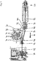
- the front end area of the suction hose 24 and the high-pressure hose 42 are held guided in the upper area of the telescopic boom 30 (see FIG 2 and 3 ).
- the suction hose 24 and the high-pressure hose 42 are routed one above the other, with the high-pressure hose 42 being routed within the profile of the telescopic boom 30 in the present example and the suction hose 24 above the profile of the telescopic boom 30.
- the suction hose is located in the area of the telescoping boom arm 32 of the telescopic boom 30 24 on roller bodies 50, which have a surface adapted to the rounded surface of the suction hose 24.
- Comparable roller bodies are also present in the arcuate front area 52 of the cantilever arm 32 in which the suction hose 24 is guided within the profile. Some of these roller bodies 50 can be motor-driven, so that the suction hose 24 can be moved back and forth in the telescopic boom 30 .
- the high-pressure hose 42 lies below the suction hose 24 in a V-shaped guide rail 54 of the telescopic boom 30. In the arcuate area 52 of the boom arm 32, the high-pressure hose 42 rests on roller bodies, which have a surface adapted to the rounded surface of the high-pressure hose 42.
- roller bodies for the high-pressure hose 42 can be motor-driven, so that the high-pressure hose 42 can be moved back and forth in the telescopic boom 30 .
- the roller bodies for the high-pressure hose 42 can be driven independently of the roller bodies 50 for the suction hose 24, so that the high-pressure hose 42 and the suction hose 24 can be wound up and unwound independently of one another.
- the telescopic boom 30 can be extended a maximum distance 60.
- the distance between the front end portion of the suction hose 24 and the high-pressure hose can be increased from the axis of rotation 26, so that a larger area around the vehicle 10 can be reached with the front end portion of the suction hose 24 and the high-pressure hose 42.
- a work area 62 can be reached around the vehicle 10 in this way.
- the work area 62 covers an angle of approximately 320 degrees around the vehicle 10 . Only a narrow angular range of about 40 degrees cannot be reached by the telescopic boom 30 in this case.
- the narrow angular range that cannot be reached by the telescopic boom 30 can be present on the left side of the vehicle as shown in the drawing or on the right side of the vehicle. To do this, the telescopic boom 30 would only have to be mirrored.
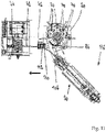
- the pivot bearing 20 has a total of five support rollers 70 in the present example (see, for example, 9 ).
- the support rollers 70 are arranged approximately in a semicircle around the axis 26 of the rotary bearing 20, so that a support roller 70 is arranged approximately every 30 to 45 degrees.
- the support rollers 70 can be moved from a first position 74 (see Figures 5 and 6 ) to a second position 76 (see Figures 7 and 8 ) can be moved back and forth.
- the support rollers 70 are at the same height as the roller bodies 40, so that the high-pressure hose 42 is guided between the roller bodies 40 and the support rollers 70.
- the high-pressure hose 42 can thus not jump out to the outside, so that an optimal operation of the vehicle 10 according to the invention is possible.
- the support rollers 70 in the present embodiment are located below the roller bodies 40.
- the support rollers 70 are moved by means of a link guide 72.
- the link guide 72 has a turntable 80 which is arranged below the roller body 40 for the high-pressure hose 42.
- the turntable 80 is attached to the pivot bearing 20 and can Rotate axis 26 of the pivot bearing. The rotation of the turntable 80 takes place together with the pivoting of the telescopic boom 30.
- a stationary guide rail 82 is present below the turntable 80.
- the stationary guide rail 82 has a first section 84 and a second section 86.
- the first section 84 and the second section 86 together form an arc of a circle.
- the second section 86 comprises an angular range of approximately 50 degrees.
- the second section 86 is arranged in the inlet area of the high-pressure hose 42 into the rotary bearing 20 (see in particular 9 ). In the area of the first section 84, the distance between the stationary guide rail 82 and the turntable 80 is smaller than in the area of the second section 86 (see FIG 4 ).
- the supporting rollers 70 each have a driving roller 88. With this driving roller 88, the supporting rollers 70 rest on the guide rail 82 and can be moved along the stationary guide rail 82.
- the support rollers 70 are each mounted in a support sleeve 90 so as to be longitudinally displaceable.
- the support sleeves 90 are attached to the turntable 80 so that the support sleeves 90 and thus also the support rollers 70 can be rotated together with the turntable 80 . If the support rollers 70 are located on the first section 84 of the guide rail 82, the support rollers 70 are in their in Figures 5 and 6 shown first position 74 available. If, on the other hand, the support rollers 70 are in the region of the second section 86 of the guide rail 82, the support rollers 70 are lowered and are thus in their in Figures 7 and 8 illustrated second position 76 available.
- the telescopic boom 30 is shown in its transport position 100 .
- the boom arm 32 of the telescopic boom 30 is in this case aligned parallel to the longitudinal direction 14 of the vehicle 10; the front end region 52 of the telescopic boom 30 is oriented counter to the direction of travel 16 towards the rear of the vehicle.
- the high-pressure hose 42 is guided from the hose reel 44 via the roller guide 46 into the telescopic boom 30 without the roller body 40 of the rotary bearing 20 coming into contact.
- the telescopic boom 30 has a pair of rollers in the area of the kink 36, between the two roller bodies 104, 106 of which the high-pressure hose 42 runs.
- the telescopic boom 30 can be pivoted a little clockwise (see 11 ).
- the telescopic boom 30 can be pivoted until the guide element 34 of the telescopic boom 30 hits a stop roller 110 of the roller guide 46 .
- this position it may be sufficient to define this position as the end position for the telescopic boom 30 .
- the roller guide 46 can be mounted on a rail 112 so that it can be displaced longitudinally.
- the telescopic boom 30 could move the contact roller 110 and thus also the roller guide 46 along the rail 112 a little in the direction of the hose reel 44 in the event of further pivoting in the clockwise direction.
- the telescopic boom 30 can be pivoted further until the 12 illustrated rear end position 114 is reached. In this rear end position 114 of the telescopic boom 30, the boom arm 32 is aligned at an angle of approximately 90 degrees to the longitudinal direction 14 of the vehicle.
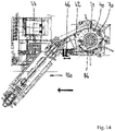
- the telescopic boom 30 can also be moved from the transport position 100 according to FIG 9 and 10 be pivoted counterclockwise so that the in 13 and 14 positions 118, 120 shown can be reached.
- boom arm 32 in the in 13 In position 118 of the telescopic boom shown, boom arm 32 is aligned at an angle of approximately 90 degrees to vehicle longitudinal direction 14, but is located on the other side of the vehicle than in FIG 12 illustrated rear end position 114.
- the high-pressure hose 42 rests on the inside of the roller body 104 in the telescopic boom.
- the high-pressure hose 42 also rests against two other roller bodies 122 , 124 which are arranged in the area of the guide element 34 of the telescopic boom 30 .
- the high-pressure hose 42 runs a little way around the pivot bearing 20 of the vehicle 10 and is in contact with some roller bodies 40 of the pivot bearing 20 .
- the high-pressure hose 41 can be guided into the rotary bearing 20 via the roller guide 46 .
- the high-pressure hose 42 loops further and further around the pivot bearing 20, so that more and more roller bodies 40 of the pivot bearing 20 are touched. So the high-pressure hose 42 lies in its in 14 illustrated front end position 120 on half of the roller body 40 of the pivot bearing 20.
- a further counter-clockwise rotation of the telescopic boom 30 is prevented by the fact that the high-pressure hose 42 has to be guided upwards from the hose reel 44 into the plane of the telescopic boom 30 .
Landscapes
- Health & Medical Sciences (AREA)
- Life Sciences & Earth Sciences (AREA)
- Engineering & Computer Science (AREA)
- Hydrology & Water Resources (AREA)
- Public Health (AREA)
- Water Supply & Treatment (AREA)
- Storing, Repeated Paying-Out, And Re-Storing Of Elongated Articles (AREA)
Claims (14)
- Véhicule (10) permettant de détacher et d'aspirer des impuretés dans les égouts et les fosses à boue, comprenant- une flèche télescopique pivotante (30) qui peut être positionnée au-dessus de l'ouverture de l'égout ou de la fosse à boue,- un tuyau souple à haute pression (42) qui est stocké de manière à pouvoir être enroulé et déroulé sur un tambour à tuyau souple (44) et peut être sorti du véhicule (10) et rentré dans la flèche télescopique (30) approximativement en parallèle de l'axe longitudinal (14) du véhicule (10),- un tuyau souple d'aspiration (24) qui peut être rétracté dans et extrait d'une unité de stockage (22) sur le véhicule (10),- dans lequel le tuyau souple à haute pression (42) et le tuyau souple d'aspiration (24) peuvent être guidés ensemble dans la flèche télescopique (30),- dans lequel la flèche télescopique (30) est fixée en rotation à un palier de pivotement (20) disposé horizontalement,- dans lequel le palier de pivotement (20) présente pour le tuyau souple à haute pression (42) des corps de galet (40) qui sont disposés en cercle autour de l'axe (26) du palier de pivotement (20),- dans lequel, dans une première position (118, 120) de la flèche télescopique (30), le tuyau souple à haute pression (42) est adjacent au moins par endroits aux corps de galet (40) du palier de pivotement (20), et dans une deuxième position (100, 114, 116) de la flèche télescopique (30), il est guidé du tambour à tuyau souple (44) à la flèche télescopique (30) sans contact avec les corps de galet (40) du palier de pivotement (20),- caractérisé en ce que- le palier de pivotement (20) présente pour le tuyau souple à haute pression (42) des galets d'appui (70) qui sont disposés autour de l'axe (26) du palier de pivotement (20),- les galets d'appui (70) peuvent être déplacés de telle sorte que, dans une première position (74), ils se trouvent approximativement au niveau des corps de galet (40) de sorte que le tuyau souple à haute pression (42) est guidé entre les corps de galet (40) et les galets d'appui (70), et dans une deuxième position (76), ils se trouvent au-dessus ou au-dessous des corps de galet (40).
- Véhicule selon la revendication 1,- caractérisé en ce que- les galets d'appui (70) sont disposés dans une plage angulaire d'environ 180 degrés.
- Véhicule selon la revendication 1 ou 2,- caractérisé en ce que- les galets d'appui (70) présentent un espacement de respectivement environ 30 à 45 degrés les uns par rapport aux autres.
- Véhicule selon l'une quelconque des revendications précédentes,- caractérisé en ce que- un guide de coulisse (72) est présent par l'intermédiaire duquel les galets d'appui (70) peuvent être déplacés de leur première position (74) à leur deuxième position (76) et à nouveau à leur première position (74).
- Véhicule selon la revendication 4,- caractérisé en ce que- le guide de coulisse (72) présente un disque rotatif (80) qui est fixé au palier de pivotement (20) et peut tourner autour de l'axe (26) du palier de pivotement (20),- le guide de coulisse (72) présente un rail de guidage stationnaire (82) qui est présent au-dessous ou au-dessus du disque rotatif (80),- les galets d'appui (70) peuvent être déplacés le long du rail de guidage stationnaire (82),- les galets d'appui (70) sont montés à coulissement vertical sur le disque rotatif (80).
- Véhicule selon la revendication 5,- caractérisé en ce que- le rail de guidage stationnaire (82) est réalisé en forme de cercle,- le rail de guidage stationnaire (82) dispose d'un premier tronçon (84) et d'un deuxième tronçon (86),- l'espacement du rail de guidage stationnaire (82) par rapport au disque rotatif (80) dans la zone du premier tronçon (84) est inférieur à celui dans la zone du deuxième tronçon (86).
- Véhicule selon la revendication 6,- caractérisé en ce que- le deuxième tronçon (86) du rail de guidage stationnaire (82) est disposé dans la zone de l'entrée du tuyau souple à haute pression (42) dans le palier de pivotement (20).
- Véhicule selon l'une quelconque des revendications 5 à 7,- caractérisé en ce que- le rail de guidage stationnaire (82) est disposé au-dessous du disque rotatif (80).
- Véhicule selon la revendication 8,- caractérisé en ce que- les galets d'appui (70) présentent respectivement au moins un galet de roulement (88),- les galets d'appui (70) peuvent se déplacer sur le rail de guidage stationnaire (82) à l'aide de leurs galets de roulement (88).
- Véhicule selon l'une quelconque des revendications précédentes 5 à 9,- caractérisé en ce que- plusieurs douilles d'appui (90) sont fixées au disque rotatif (80),- les galets d'appui (70) sont montés à coulissement longitudinal dans les douilles d'appui (90) du disque rotatif (80).
- Véhicule selon l'une quelconque des revendications précédentes,- caractérisé en ce que- le tuyau souple à haute pression (42) peut être guidé par l'intermédiaire d'un guidage de galet (46) du tambour à tuyau souple (44) à la flèche télescopique (30),- le guidage de galet (46) est monté à coulissement longitudinal le long de l'axe longitudinal (14) du véhicule (10).
- Véhicule selon la revendication 11,- caractérisé en ce que- le guidage de galet (46) peut être déplacé par la flèche télescopique (30) dans la direction du tambour à tuyau souple (44) pour le tuyau souple à haute pression (42) .
- Véhicule selon la revendication 12,- caractérisé en ce que- le guidage de galet (46) présente un galet de démarrage (110) qui permet à la flèche télescopique (30) de déplacer le guidage de galet (46).
- Véhicule selon l'une quelconque des revendications 11 à 13,- caractérisé en ce que- le guidage de galet (46) peut être ramené dans sa position de départ par une force de rappel, en particulier par l'intermédiaire d'un ressort à gaz ou d'un vérin pneumatique.
Priority Applications (2)
| Application Number | Priority Date | Filing Date | Title |
|---|---|---|---|
| EP20194995.5A EP3964657B1 (fr) | 2020-09-08 | 2020-09-08 | Véhicule de nettoyage de canal |
| DK20194995.5T DK3964657T3 (da) | 2020-09-08 | 2020-09-08 | Kanalrengøringskøretøj |
Applications Claiming Priority (1)
| Application Number | Priority Date | Filing Date | Title |
|---|---|---|---|
| EP20194995.5A EP3964657B1 (fr) | 2020-09-08 | 2020-09-08 | Véhicule de nettoyage de canal |
Publications (2)
| Publication Number | Publication Date |
|---|---|
| EP3964657A1 EP3964657A1 (fr) | 2022-03-09 |
| EP3964657B1 true EP3964657B1 (fr) | 2022-11-16 |
Family
ID=72428225
Family Applications (1)
| Application Number | Title | Priority Date | Filing Date |
|---|---|---|---|
| EP20194995.5A Active EP3964657B1 (fr) | 2020-09-08 | 2020-09-08 | Véhicule de nettoyage de canal |
Country Status (2)
| Country | Link |
|---|---|
| EP (1) | EP3964657B1 (fr) |
| DK (1) | DK3964657T3 (fr) |
Citations (2)
| Publication number | Priority date | Publication date | Assignee | Title |
|---|---|---|---|---|
| EP0698696B1 (fr) * | 1994-07-11 | 1998-01-14 | Peter Assmann | Véhicule pour le nettoyage de canalisations d'égouts |
| EP2884017B1 (fr) * | 2013-12-12 | 2018-07-04 | Müller Umwelttechnik GmbH & Co. KG | Dispositif de guidage d'un tuyau d'aspiration et d'au moins un tuyau de rinçage |
Family Cites Families (1)
| Publication number | Priority date | Publication date | Assignee | Title |
|---|---|---|---|---|
| DE202016002943U1 (de) | 2016-05-09 | 2016-06-10 | Frank Assmann | Kanalreinigungsfahrzeug |
-
2020
- 2020-09-08 DK DK20194995.5T patent/DK3964657T3/da active
- 2020-09-08 EP EP20194995.5A patent/EP3964657B1/fr active Active
Patent Citations (2)
| Publication number | Priority date | Publication date | Assignee | Title |
|---|---|---|---|---|
| EP0698696B1 (fr) * | 1994-07-11 | 1998-01-14 | Peter Assmann | Véhicule pour le nettoyage de canalisations d'égouts |
| EP2884017B1 (fr) * | 2013-12-12 | 2018-07-04 | Müller Umwelttechnik GmbH & Co. KG | Dispositif de guidage d'un tuyau d'aspiration et d'au moins un tuyau de rinçage |
Also Published As
| Publication number | Publication date |
|---|---|
| EP3964657A1 (fr) | 2022-03-09 |
| DK3964657T3 (da) | 2023-02-06 |
Similar Documents
| Publication | Publication Date | Title |
|---|---|---|
| DE60017632T2 (de) | Vorrichtung zum Abwickeln/Aufwickeln eines Saugschlauches zum Entleeren von Senkgruben und Faulgruben im allgemeinen | |
| DE2846470C2 (de) | Bewegliches Hubgerät | |
| DE2822466A1 (de) | Rollenanordnung zum aufbewahren, zufuehren und auf- bzw. abwickeln langgestreckter materialien | |
| EP3269888B1 (fr) | Véhicule de nettoyage de canal | |
| DE102009038582B4 (de) | Vorrichtung zur Kanalreinigung | |
| DE202016002943U1 (de) | Kanalreinigungsfahrzeug | |
| DE9411184U1 (de) | Kanalreinigungsfahrzeug | |
| DE102009042687A1 (de) | Kanalreinigungsfahrzeug | |
| EP3249124A1 (fr) | Véhicule comprenant un dispositif de nettoyage de canal | |
| DE4417126C2 (de) | Kanalreinigungsfahrzeug | |
| EP3964657B1 (fr) | Véhicule de nettoyage de canal | |
| AT403712B (de) | Kanalreinigungsfahrzeug | |
| EP3859092B1 (fr) | Véhicule de nettoyage de canal | |
| DE10246041A1 (de) | Saug-Spülfahrzeug | |
| EP3279044A1 (fr) | Machine de travail mobile | |
| EP0995848A2 (fr) | Dispositif d'aspiration des matériaux aspirables, en particulier de déchets, de boue, de matières fécales ou analogues | |
| DE4013992A1 (de) | Mobile feld-beregnungseinrichtung | |
| DE29909623U1 (de) | Fahrzeug zum Lösen und Absaugen von Verunreinigungen aus Straßenabläufen | |
| DE3038339C2 (de) | Vorrichtung zum Füllen von Behältern, insbesondere von Güllefässern | |
| DE102006018014B4 (de) | Aufnahmevorrichtung für einen Saugschlauch | |
| DE10115346A1 (de) | Umlenkgerät für Versorgungsleitungen von Kanalsonden | |
| DE19512115A1 (de) | Fahrzeugaufbau für Kanalreinigungsfahrzeuge | |
| AT243104B (de) | Fahrzeug zum Abtransport unreiner Flüssigkeiten und Aufschwemmungen, insbesondere Kanalräumwagen | |
| EP1712414B1 (fr) | Véhicule pour le nettoyage de canalisations d'égouts | |
| DE4141494A1 (de) | Schutzvorrichtung fuer sonderfahrzeuge |
Legal Events
| Date | Code | Title | Description |
|---|---|---|---|
| PUAI | Public reference made under article 153(3) epc to a published international application that has entered the european phase |
Free format text: ORIGINAL CODE: 0009012 |
|
| STAA | Information on the status of an ep patent application or granted ep patent |
Free format text: STATUS: THE APPLICATION HAS BEEN PUBLISHED |
|
| AK | Designated contracting states |
Kind code of ref document: A1 Designated state(s): AL AT BE BG CH CY CZ DE DK EE ES FI FR GB GR HR HU IE IS IT LI LT LU LV MC MK MT NL NO PL PT RO RS SE SI SK SM TR |
|
| STAA | Information on the status of an ep patent application or granted ep patent |
Free format text: STATUS: REQUEST FOR EXAMINATION WAS MADE |
|
| 17P | Request for examination filed |
Effective date: 20220329 |
|
| RBV | Designated contracting states (corrected) |
Designated state(s): AL AT BE BG CH CY CZ DE DK EE ES FI FR GB GR HR HU IE IS IT LI LT LU LV MC MK MT NL NO PL PT RO RS SE SI SK SM TR |
|
| GRAP | Despatch of communication of intention to grant a patent |
Free format text: ORIGINAL CODE: EPIDOSNIGR1 |
|
| STAA | Information on the status of an ep patent application or granted ep patent |
Free format text: STATUS: GRANT OF PATENT IS INTENDED |
|
| INTG | Intention to grant announced |
Effective date: 20220719 |
|
| GRAS | Grant fee paid |
Free format text: ORIGINAL CODE: EPIDOSNIGR3 |
|
| GRAA | (expected) grant |
Free format text: ORIGINAL CODE: 0009210 |
|
| STAA | Information on the status of an ep patent application or granted ep patent |
Free format text: STATUS: THE PATENT HAS BEEN GRANTED |
|
| AK | Designated contracting states |
Kind code of ref document: B1 Designated state(s): AL AT BE BG CH CY CZ DE DK EE ES FI FR GB GR HR HU IE IS IT LI LT LU LV MC MK MT NL NO PL PT RO RS SE SI SK SM TR |
|
| REG | Reference to a national code |
Ref country code: GB Ref legal event code: FG4D Free format text: NOT ENGLISH |
|
| REG | Reference to a national code |
Ref country code: CH Ref legal event code: EP |
|
| REG | Reference to a national code |
Ref country code: IE Ref legal event code: FG4D Free format text: LANGUAGE OF EP DOCUMENT: GERMAN |
|
| REG | Reference to a national code |
Ref country code: DE Ref legal event code: R096 Ref document number: 502020002001 Country of ref document: DE |
|
| REG | Reference to a national code |
Ref country code: AT Ref legal event code: REF Ref document number: 1531852 Country of ref document: AT Kind code of ref document: T Effective date: 20221215 |
|
| REG | Reference to a national code |
Ref country code: DK Ref legal event code: T3 Effective date: 20230131 |
|
| REG | Reference to a national code |
Ref country code: LT Ref legal event code: MG9D |
|
| REG | Reference to a national code |
Ref country code: NL Ref legal event code: MP Effective date: 20221116 |
|
| PG25 | Lapsed in a contracting state [announced via postgrant information from national office to epo] |
Ref country code: SE Free format text: LAPSE BECAUSE OF FAILURE TO SUBMIT A TRANSLATION OF THE DESCRIPTION OR TO PAY THE FEE WITHIN THE PRESCRIBED TIME-LIMIT Effective date: 20221116 Ref country code: PT Free format text: LAPSE BECAUSE OF FAILURE TO SUBMIT A TRANSLATION OF THE DESCRIPTION OR TO PAY THE FEE WITHIN THE PRESCRIBED TIME-LIMIT Effective date: 20230316 Ref country code: NO Free format text: LAPSE BECAUSE OF FAILURE TO SUBMIT A TRANSLATION OF THE DESCRIPTION OR TO PAY THE FEE WITHIN THE PRESCRIBED TIME-LIMIT Effective date: 20230216 Ref country code: LT Free format text: LAPSE BECAUSE OF FAILURE TO SUBMIT A TRANSLATION OF THE DESCRIPTION OR TO PAY THE FEE WITHIN THE PRESCRIBED TIME-LIMIT Effective date: 20221116 Ref country code: FI Free format text: LAPSE BECAUSE OF FAILURE TO SUBMIT A TRANSLATION OF THE DESCRIPTION OR TO PAY THE FEE WITHIN THE PRESCRIBED TIME-LIMIT Effective date: 20221116 Ref country code: ES Free format text: LAPSE BECAUSE OF FAILURE TO SUBMIT A TRANSLATION OF THE DESCRIPTION OR TO PAY THE FEE WITHIN THE PRESCRIBED TIME-LIMIT Effective date: 20221116 |
|
| PG25 | Lapsed in a contracting state [announced via postgrant information from national office to epo] |
Ref country code: RS Free format text: LAPSE BECAUSE OF FAILURE TO SUBMIT A TRANSLATION OF THE DESCRIPTION OR TO PAY THE FEE WITHIN THE PRESCRIBED TIME-LIMIT Effective date: 20221116 Ref country code: PL Free format text: LAPSE BECAUSE OF FAILURE TO SUBMIT A TRANSLATION OF THE DESCRIPTION OR TO PAY THE FEE WITHIN THE PRESCRIBED TIME-LIMIT Effective date: 20221116 Ref country code: LV Free format text: LAPSE BECAUSE OF FAILURE TO SUBMIT A TRANSLATION OF THE DESCRIPTION OR TO PAY THE FEE WITHIN THE PRESCRIBED TIME-LIMIT Effective date: 20221116 Ref country code: IS Free format text: LAPSE BECAUSE OF FAILURE TO SUBMIT A TRANSLATION OF THE DESCRIPTION OR TO PAY THE FEE WITHIN THE PRESCRIBED TIME-LIMIT Effective date: 20230316 Ref country code: HR Free format text: LAPSE BECAUSE OF FAILURE TO SUBMIT A TRANSLATION OF THE DESCRIPTION OR TO PAY THE FEE WITHIN THE PRESCRIBED TIME-LIMIT Effective date: 20221116 Ref country code: GR Free format text: LAPSE BECAUSE OF FAILURE TO SUBMIT A TRANSLATION OF THE DESCRIPTION OR TO PAY THE FEE WITHIN THE PRESCRIBED TIME-LIMIT Effective date: 20230217 |
|
| PG25 | Lapsed in a contracting state [announced via postgrant information from national office to epo] |
Ref country code: NL Free format text: LAPSE BECAUSE OF FAILURE TO SUBMIT A TRANSLATION OF THE DESCRIPTION OR TO PAY THE FEE WITHIN THE PRESCRIBED TIME-LIMIT Effective date: 20221116 |
|
| PG25 | Lapsed in a contracting state [announced via postgrant information from national office to epo] |
Ref country code: SM Free format text: LAPSE BECAUSE OF FAILURE TO SUBMIT A TRANSLATION OF THE DESCRIPTION OR TO PAY THE FEE WITHIN THE PRESCRIBED TIME-LIMIT Effective date: 20221116 Ref country code: RO Free format text: LAPSE BECAUSE OF FAILURE TO SUBMIT A TRANSLATION OF THE DESCRIPTION OR TO PAY THE FEE WITHIN THE PRESCRIBED TIME-LIMIT Effective date: 20221116 Ref country code: EE Free format text: LAPSE BECAUSE OF FAILURE TO SUBMIT A TRANSLATION OF THE DESCRIPTION OR TO PAY THE FEE WITHIN THE PRESCRIBED TIME-LIMIT Effective date: 20221116 Ref country code: CZ Free format text: LAPSE BECAUSE OF FAILURE TO SUBMIT A TRANSLATION OF THE DESCRIPTION OR TO PAY THE FEE WITHIN THE PRESCRIBED TIME-LIMIT Effective date: 20221116 |
|
| REG | Reference to a national code |
Ref country code: DE Ref legal event code: R097 Ref document number: 502020002001 Country of ref document: DE |
|
| PG25 | Lapsed in a contracting state [announced via postgrant information from national office to epo] |
Ref country code: SK Free format text: LAPSE BECAUSE OF FAILURE TO SUBMIT A TRANSLATION OF THE DESCRIPTION OR TO PAY THE FEE WITHIN THE PRESCRIBED TIME-LIMIT Effective date: 20221116 Ref country code: AL Free format text: LAPSE BECAUSE OF FAILURE TO SUBMIT A TRANSLATION OF THE DESCRIPTION OR TO PAY THE FEE WITHIN THE PRESCRIBED TIME-LIMIT Effective date: 20221116 |
|
| PLBE | No opposition filed within time limit |
Free format text: ORIGINAL CODE: 0009261 |
|
| STAA | Information on the status of an ep patent application or granted ep patent |
Free format text: STATUS: NO OPPOSITION FILED WITHIN TIME LIMIT |
|
| 26N | No opposition filed |
Effective date: 20230817 |
|
| PG25 | Lapsed in a contracting state [announced via postgrant information from national office to epo] |
Ref country code: SI Free format text: LAPSE BECAUSE OF FAILURE TO SUBMIT A TRANSLATION OF THE DESCRIPTION OR TO PAY THE FEE WITHIN THE PRESCRIBED TIME-LIMIT Effective date: 20221116 |
|
| REG | Reference to a national code |
Ref country code: DE Ref legal event code: R082 Ref document number: 502020002001 Country of ref document: DE Representative=s name: GLEIM PETRI PATENT- UND RECHTSANWALTSPARTNERSC, DE |
|
| PGFP | Annual fee paid to national office [announced via postgrant information from national office to epo] |
Ref country code: IT Payment date: 20230930 Year of fee payment: 4 Ref country code: CH Payment date: 20231001 Year of fee payment: 4 |
|
| PG25 | Lapsed in a contracting state [announced via postgrant information from national office to epo] |
Ref country code: LU Free format text: LAPSE BECAUSE OF NON-PAYMENT OF DUE FEES Effective date: 20230908 |
|
| REG | Reference to a national code |
Ref country code: BE Ref legal event code: MM Effective date: 20230930 |
|
| PG25 | Lapsed in a contracting state [announced via postgrant information from national office to epo] |
Ref country code: LU Free format text: LAPSE BECAUSE OF NON-PAYMENT OF DUE FEES Effective date: 20230908 Ref country code: MC Free format text: LAPSE BECAUSE OF FAILURE TO SUBMIT A TRANSLATION OF THE DESCRIPTION OR TO PAY THE FEE WITHIN THE PRESCRIBED TIME-LIMIT Effective date: 20221116 |
|
| REG | Reference to a national code |
Ref country code: IE Ref legal event code: MM4A |
|
| PG25 | Lapsed in a contracting state [announced via postgrant information from national office to epo] |
Ref country code: IE Free format text: LAPSE BECAUSE OF NON-PAYMENT OF DUE FEES Effective date: 20230908 |
|
| PG25 | Lapsed in a contracting state [announced via postgrant information from national office to epo] |
Ref country code: IE Free format text: LAPSE BECAUSE OF NON-PAYMENT OF DUE FEES Effective date: 20230908 |
|
| PG25 | Lapsed in a contracting state [announced via postgrant information from national office to epo] |
Ref country code: BE Free format text: LAPSE BECAUSE OF NON-PAYMENT OF DUE FEES Effective date: 20230930 |
|
| PGFP | Annual fee paid to national office [announced via postgrant information from national office to epo] |
Ref country code: DE Payment date: 20240925 Year of fee payment: 5 |
|
| PGFP | Annual fee paid to national office [announced via postgrant information from national office to epo] |
Ref country code: DK Payment date: 20240920 Year of fee payment: 5 |
|
| PGFP | Annual fee paid to national office [announced via postgrant information from national office to epo] |
Ref country code: FR Payment date: 20240924 Year of fee payment: 5 |