EP3951176B1 - Sealed compressor and refrigeration cycle device - Google Patents
Sealed compressor and refrigeration cycle device Download PDFInfo
- Publication number
- EP3951176B1 EP3951176B1 EP20776408.5A EP20776408A EP3951176B1 EP 3951176 B1 EP3951176 B1 EP 3951176B1 EP 20776408 A EP20776408 A EP 20776408A EP 3951176 B1 EP3951176 B1 EP 3951176B1
- Authority
- EP
- European Patent Office
- Prior art keywords
- roller
- blade
- equal
- wear
- sealed compressor
- Prior art date
- Legal status (The legal status is an assumption and is not a legal conclusion. Google has not performed a legal analysis and makes no representation as to the accuracy of the status listed.)
- Active
Links
Images


Classifications
-
- C—CHEMISTRY; METALLURGY
- C01—INORGANIC CHEMISTRY
- C01B—NON-METALLIC ELEMENTS; COMPOUNDS THEREOF; METALLOIDS OR COMPOUNDS THEREOF NOT COVERED BY SUBCLASS C01C
- C01B32/00—Carbon; Compounds thereof
- C01B32/05—Preparation or purification of carbon not covered by groups C01B32/15, C01B32/20, C01B32/25, C01B32/30
-
- C—CHEMISTRY; METALLURGY
- C21—METALLURGY OF IRON
- C21D—MODIFYING THE PHYSICAL STRUCTURE OF FERROUS METALS; GENERAL DEVICES FOR HEAT TREATMENT OF FERROUS OR NON-FERROUS METALS OR ALLOYS; MAKING METAL MALLEABLE, e.g. BY DECARBURISATION OR TEMPERING
- C21D5/00—Heat treatments of cast-iron
-
- C—CHEMISTRY; METALLURGY
- C22—METALLURGY; FERROUS OR NON-FERROUS ALLOYS; TREATMENT OF ALLOYS OR NON-FERROUS METALS
- C22C—ALLOYS
- C22C37/00—Cast-iron alloys
- C22C37/04—Cast-iron alloys containing spheroidal graphite
-
- F—MECHANICAL ENGINEERING; LIGHTING; HEATING; WEAPONS; BLASTING
- F04—POSITIVE - DISPLACEMENT MACHINES FOR LIQUIDS; PUMPS FOR LIQUIDS OR ELASTIC FLUIDS
- F04C—ROTARY-PISTON, OR OSCILLATING-PISTON, POSITIVE-DISPLACEMENT MACHINES FOR LIQUIDS; ROTARY-PISTON, OR OSCILLATING-PISTON, POSITIVE-DISPLACEMENT PUMPS
- F04C18/00—Rotary-piston pumps specially adapted for elastic fluids
- F04C18/30—Rotary-piston pumps specially adapted for elastic fluids having the characteristics covered by two or more of groups F04C18/02, F04C18/08, F04C18/22, F04C18/24, F04C18/48, or having the characteristics covered by one of these groups together with some other type of movement between co-operating members
- F04C18/34—Rotary-piston pumps specially adapted for elastic fluids having the characteristics covered by two or more of groups F04C18/02, F04C18/08, F04C18/22, F04C18/24, F04C18/48, or having the characteristics covered by one of these groups together with some other type of movement between co-operating members having the movement defined in group F04C18/08 or F04C18/22 and relative reciprocation between the co-operating members
- F04C18/356—Rotary-piston pumps specially adapted for elastic fluids having the characteristics covered by two or more of groups F04C18/02, F04C18/08, F04C18/22, F04C18/24, F04C18/48, or having the characteristics covered by one of these groups together with some other type of movement between co-operating members having the movement defined in group F04C18/08 or F04C18/22 and relative reciprocation between the co-operating members with vanes reciprocating with respect to the outer member
- F04C18/3562—Rotary-piston pumps specially adapted for elastic fluids having the characteristics covered by two or more of groups F04C18/02, F04C18/08, F04C18/22, F04C18/24, F04C18/48, or having the characteristics covered by one of these groups together with some other type of movement between co-operating members having the movement defined in group F04C18/08 or F04C18/22 and relative reciprocation between the co-operating members with vanes reciprocating with respect to the outer member the inner and outer member being in contact along one line or continuous surfaces substantially parallel to the axis of rotation
-
- F—MECHANICAL ENGINEERING; LIGHTING; HEATING; WEAPONS; BLASTING
- F04—POSITIVE - DISPLACEMENT MACHINES FOR LIQUIDS; PUMPS FOR LIQUIDS OR ELASTIC FLUIDS
- F04C—ROTARY-PISTON, OR OSCILLATING-PISTON, POSITIVE-DISPLACEMENT MACHINES FOR LIQUIDS; ROTARY-PISTON, OR OSCILLATING-PISTON, POSITIVE-DISPLACEMENT PUMPS
- F04C23/00—Combinations of two or more pumps, each being of rotary-piston or oscillating-piston type, specially adapted for elastic fluids; Pumping installations specially adapted for elastic fluids; Multi-stage pumps specially adapted for elastic fluids
- F04C23/008—Hermetic pumps
-
- C—CHEMISTRY; METALLURGY
- C21—METALLURGY OF IRON
- C21D—MODIFYING THE PHYSICAL STRUCTURE OF FERROUS METALS; GENERAL DEVICES FOR HEAT TREATMENT OF FERROUS OR NON-FERROUS METALS OR ALLOYS; MAKING METAL MALLEABLE, e.g. BY DECARBURISATION OR TEMPERING
- C21D1/00—General methods or devices for heat treatment, e.g. annealing, hardening, quenching or tempering
- C21D1/18—Hardening; Quenching with or without subsequent tempering
- C21D1/25—Hardening, combined with annealing between 300 degrees Celsius and 600 degrees Celsius, i.e. heat refining ("Vergüten")
-
- C—CHEMISTRY; METALLURGY
- C21—METALLURGY OF IRON
- C21D—MODIFYING THE PHYSICAL STRUCTURE OF FERROUS METALS; GENERAL DEVICES FOR HEAT TREATMENT OF FERROUS OR NON-FERROUS METALS OR ALLOYS; MAKING METAL MALLEABLE, e.g. BY DECARBURISATION OR TEMPERING
- C21D2211/00—Microstructure comprising significant phases
- C21D2211/004—Dispersions; Precipitations
-
- C—CHEMISTRY; METALLURGY
- C21—METALLURGY OF IRON
- C21D—MODIFYING THE PHYSICAL STRUCTURE OF FERROUS METALS; GENERAL DEVICES FOR HEAT TREATMENT OF FERROUS OR NON-FERROUS METALS OR ALLOYS; MAKING METAL MALLEABLE, e.g. BY DECARBURISATION OR TEMPERING
- C21D9/00—Heat treatment, e.g. annealing, hardening, quenching or tempering, adapted for particular articles; Furnaces therefor
- C21D9/38—Heat treatment, e.g. annealing, hardening, quenching or tempering, adapted for particular articles; Furnaces therefor for roll bodies
-
- C—CHEMISTRY; METALLURGY
- C22—METALLURGY; FERROUS OR NON-FERROUS ALLOYS; TREATMENT OF ALLOYS OR NON-FERROUS METALS
- C22C—ALLOYS
- C22C38/00—Ferrous alloys, e.g. steel alloys
-
- C—CHEMISTRY; METALLURGY
- C22—METALLURGY; FERROUS OR NON-FERROUS ALLOYS; TREATMENT OF ALLOYS OR NON-FERROUS METALS
- C22C—ALLOYS
- C22C38/00—Ferrous alloys, e.g. steel alloys
- C22C38/12—Ferrous alloys, e.g. steel alloys containing tungsten, tantalum, molybdenum, vanadium, or niobium
-
- F—MECHANICAL ENGINEERING; LIGHTING; HEATING; WEAPONS; BLASTING
- F04—POSITIVE - DISPLACEMENT MACHINES FOR LIQUIDS; PUMPS FOR LIQUIDS OR ELASTIC FLUIDS
- F04C—ROTARY-PISTON, OR OSCILLATING-PISTON, POSITIVE-DISPLACEMENT MACHINES FOR LIQUIDS; ROTARY-PISTON, OR OSCILLATING-PISTON, POSITIVE-DISPLACEMENT PUMPS
- F04C2210/00—Fluid
- F04C2210/26—Refrigerants with particular properties, e.g. HFC-134a
-
- F—MECHANICAL ENGINEERING; LIGHTING; HEATING; WEAPONS; BLASTING
- F04—POSITIVE - DISPLACEMENT MACHINES FOR LIQUIDS; PUMPS FOR LIQUIDS OR ELASTIC FLUIDS
- F04C—ROTARY-PISTON, OR OSCILLATING-PISTON, POSITIVE-DISPLACEMENT MACHINES FOR LIQUIDS; ROTARY-PISTON, OR OSCILLATING-PISTON, POSITIVE-DISPLACEMENT PUMPS
- F04C2230/00—Manufacture
- F04C2230/90—Improving properties of machine parts
- F04C2230/91—Coating
-
- F—MECHANICAL ENGINEERING; LIGHTING; HEATING; WEAPONS; BLASTING
- F05—INDEXING SCHEMES RELATING TO ENGINES OR PUMPS IN VARIOUS SUBCLASSES OF CLASSES F01-F04
- F05C—INDEXING SCHEME RELATING TO MATERIALS, MATERIAL PROPERTIES OR MATERIAL CHARACTERISTICS FOR MACHINES, ENGINES OR PUMPS OTHER THAN NON-POSITIVE-DISPLACEMENT MACHINES OR ENGINES
- F05C2201/00—Metals
- F05C2201/04—Heavy metals
- F05C2201/0433—Iron group; Ferrous alloys, e.g. steel
- F05C2201/0436—Iron
- F05C2201/0439—Cast iron
-
- F—MECHANICAL ENGINEERING; LIGHTING; HEATING; WEAPONS; BLASTING
- F05—INDEXING SCHEMES RELATING TO ENGINES OR PUMPS IN VARIOUS SUBCLASSES OF CLASSES F01-F04
- F05C—INDEXING SCHEME RELATING TO MATERIALS, MATERIAL PROPERTIES OR MATERIAL CHARACTERISTICS FOR MACHINES, ENGINES OR PUMPS OTHER THAN NON-POSITIVE-DISPLACEMENT MACHINES OR ENGINES
- F05C2251/00—Material properties
- F05C2251/10—Hardness
Definitions
- Embodiments described herein relate generally to a sealed compressor and a refrigeration cycle device.
- a refrigeration cycle device such as an air conditioner for cooling and heating a room, a refrigerator, a refrigeration showcase or a heat pump water heater incorporates a sealed compressor therein, and circulates a refrigerant such as an HFC-based refrigerant or a natural refrigerant such as an HC based or CO 2 refrigerant.
- a refrigerant such as an HFC-based refrigerant or a natural refrigerant such as an HC based or CO 2 refrigerant.
- the sealed compressor comprises a sealed container, an electric motor part housed in the sealed container, and a compression mechanism part connected to the electric motor part via a rotary shaft.
- a cylinder is provided in the compression mechanism part.
- a roller is arranged in the cylinder, and the tip of a blade elastically contacts the peripheral surface of the roller.
- JP 5113902 B discloses a sealed compressor comprising a compression mechanism part. At least one of sliding members of the compression mechanism part, for example, a blade is formed of tool steel. On the sliding surface of the tip of the blade with a roller, a single layer of chromium, a chromium and tungsten carbide alloy layer, an amorphous carbon layer containing tungsten, and an amorphous carbon layer containing carbon and hydrogen without containing metal are stacked in this order from the surface of the substrate of the tool steel.
- the document US 2013 118652 discloses a compressor which sliding parts provide a predetermined hardness and carbon percentage within the material.
- the present invention provides a sealed compressor capable of ensuring wear resistance even in a sliding environment in which a first member and a second member sliding with each other of a compression mechanism part, for example, a blade and a roller are in a one-sided contact state, and a refrigeration cycle device comprising the compressor.
- a sealed compressor comprising a compression mechanism part compressing a refrigerant in a sealed container, and a refrigerator oil.
- the compression mechanism part comprises a first member and a second member sliding with each other.
- the first member is a substrate which is made of iron-based metal and has a diamond-like carbon film on a surface of the substrate.
- the second member is formed of cast iron with magnesium added, has an amount of carbide precipitation on a sliding surface with the first member of less than or equal to 5% in area ratio, and has a Rockwell hardness (HRC) of greater than or equal to 40 but less than or equal to 55.
- HRC Rockwell hardness
- FIG. 1 is a schematic view showing a refrigeration cycle device 1 according to an embodiment.
- the refrigeration cycle device 1 comprises a sealed compressor 2, a condenser 3, an expander 4 and an evaporator 5.
- a refrigerant is circulated from the discharge side of the sealed compressor 2 to the suction side of the sealed compressor 2 via the condenser 3, the expander 4, the evaporator 5 and an accumulator 6.
- the sealed compressor 2 is, for example, a vertical rotary compressor, and comprises a sealed container 10, a compression mechanism part 11 and an electric motor part 12 as main components.
- the sealed container 10 has a cylindrical peripheral wall 10a, and is raised along the vertical direction.
- a discharge pipe 10b is provided at the upper end of the sealed container 10.
- the discharge pipe 10b is connected to the condenser 3.
- an oil reservoir part 10c which stores a refrigerator oil I for lubricating the compression mechanism part 11 is provided in the lower part of the sealed container 10.
- the compression mechanism part 11 is housed in the lower part of the sealed container 10 such that the compression mechanism part 11 is immersed in the refrigerator oil I.
- the compression mechanism part 11 has a twin cylinder structure, and comprises a first cylinder 13, a second cylinder 14, a rotary shaft 15, a first roller 16, a second roller 17, a first blade 30a and a second blade 30b as main components.
- the first cylinder 13 is fixed to the inner peripheral surface of the peripheral wall 10a of the sealed container 10.
- the second cylinder 14 is fixed to the lower surface of the first cylinder 13 via an intermediate partition plate 18.
- a first bearing 20 is fixed to the upper surface of the first cylinder 13.
- the first bearing 20 covers the inner diameter part of the first cylinder 13 from above, and protrudes toward above the first cylinder 13.
- a space enclosed by the inner diameter part of the first cylinder 13, the intermediate partition plate 18 and the first bearing 20 constitute a first cylinder chamber 21.
- the intermediate partition plate 18 and the first bearing 20 are the closing members of the first cylinder chamber 21.
- a second bearing 22 is fixed to the lower surface of the second cylinder 14.
- the second bearing 22 covers the inner diameter part of the second cylinder 14 from below, and protrudes toward below the second cylinder 14.
- a space enclosed by the inner diameter part of the second cylinder 14, the intermediate partition plate 18 and the second bearing 22 constitute a second cylinder chamber 23.
- the intermediate partition plate 18 and the second bearing 22 are the closing members of the second cylinder chamber 23.
- the first cylinder chamber 21 and the second cylinder chamber 23 are located coaxially with respect to a central axis O1 of the sealed container 10.
- the first cylinder chamber 21 and the second cylinder chamber 23 are connected to the accumulator 6 via suction pipes 25a and 25b.
- the gas-phase refrigerant separated from the liquid-phase refrigerant in the accumulator 6 is guided to the first cylinder chamber 21 and the second cylinder chamber 23 through the suction pipes 25a and 25b.
- the rotary shaft 15 is coaxially located on the central axis O1 of the sealed container 10, and penetrates the first cylinder chamber 21, the second cylinder chamber 23 and the intermediate partition plate 18.
- the rotary shaft 15 has a first journal part 27a, a second journal part 27b and a pair of eccentric parts 28a and 28b.
- the first journal part 27a is rotatably supported by the first bearing 20.
- the second journal part 27b is rotatably supported by the second bearing 22.
- the rotary shaft 15 has a connecting part 27c coaxially extending from the first journal part 27a.
- a rotor 33 of the electric motor part 12 is firmly attached to the connecting part 27c.
- the eccentric parts 28a and 28b are located between the first journal part 27a and the second journal part 27b.
- the eccentric parts 28a and 28b have a phase difference of, for example, 180 degrees, and have the same amount of eccentricity with respect to the central axis O1 of the sealed container 10.
- One eccentric part 28a is housed in the first cylinder chamber 21.
- the other eccentric part 28b is housed in the second cylinder chamber 23.
- the ring-shaped first roller 16 is fitted to the outer peripheral surface of the one eccentric part 28a.
- the first roller 16 rotates eccentrically in the first cylinder chamber 21, and a part of the outer peripheral surface of the first roller 16 slidably makes line contact with the inner peripheral surface of the first cylinder chamber 21 via an oil film.
- the ring-shaped second roller 17 is fitted to the outer peripheral surface of the other eccentric part 28b.
- the second roller 17 rotates eccentrically in the second cylinder chamber 23, and a part of the outer peripheral surface of the second roller 17 slidably makes line contact with the inner peripheral surface of the second cylinder chamber 23 via an oil film.
- the first blade 30a is supported by the first cylinder 13.
- the tip of the first blade 30a is slidably pressed against the outer peripheral surface of the first roller 16.
- the first blade 30a cooperates with the first roller 16, and partitions the first cylinder chamber 21 into a suction region and a compression region.
- the first blade 30a follows the eccentric motion of the first roller 16, and moves in a direction of protruding into the first cylinder chamber 21 or retreating from the first cylinder chamber 21. This operation of the first blade 30a changes the volumes of the suction region and the compression region of the first cylinder chamber 21, and compresses the gas-phase refrigerant sucked from the suction pipe 25a into the first cylinder chamber 21.
- the second blade 30b is supported by the second cylinder 14.
- the tip of the second blade 30b is slidably pressed against the outer peripheral surface of the second roller 17.
- the second blade 30b and the second roller 17 cooperate with each other in the same manner as the first blade 30a and the first roller 16. Therefore, when the second roller 14 moves eccentrically in the second cylinder chamber 23, the volumes of the suction region and the compression region of the second cylinder chamber 23 are changed, and the gas-phase refrigerant sucked from the suction pipe 25b into the second cylinder chamber 23 is compressed.
- the high-temperature and high-pressure gas-phase refrigerant compressed in the first cylinder chamber 21 and the second cylinder chamber 23 is discharged into the sealed container 10 via an unillustrated discharge valve mechanism.
- the discharged gas-phase refrigerant rises in the sealed container 10.
- the electric motor part 12 is housed in the intermediate part along the axial direction of the sealed container 10 such that the electric motor part 12 is located between the compression mechanism part 11 and the discharge pipe 10b as shown in FIG. 1 .
- the electric motor part 12 is what is called an inner roller type motor, and comprises the rotor 33 and a stator 34.
- centrifugal oil separator 35 which separates the refrigerator oil I contained in the gas-phase refrigerant in the sealed container 10 is installed.
- first and second blades 30a and 30b for example, first and second blades 30a and 30b
- second member for example, first and second rollers 16 and 17
- the shaft rotary shaft 15
- closing members which constitute the compression mechanism part 11 of the sealed compressor 2 described above
- the first member (for example, the first and second blades 30a and 30b) has a structure in which the surface of a substrate made of iron-based metal is coated with a diamond-like carbon film (DLC film).
- DLC film diamond-like carbon film
- the iron-based metal is metal which is primarily composed of iron, and contains carbon and metal other than iron such as Cr, Ni, Mn or Si.
- Preferred iron-based metal is high-speed tool steel (SKH steel), specifically, tungsten-based SKH2 to SKH4, etc., or molybdenum-based SKH50 to SKH59, etc.
- SKD11 alloy steel, die steel
- DLC diamond-like carbon
- the DLC film may be formed on at least the sliding surface of the substrate with the second member. It is preferable that the DLC film should have a thickness of greater than or equal to 1 ⁇ m but less than or equal to 3 ⁇ m.
- the DLC film should have a base layer between it and the substrate in order to improve adhesion to the substrate.
- the base layer should be composed of a first layer made of a single layer of chromium, a second layer made of a chromium-tungsten carbide alloy layer, and a third layer made of a metal-containing amorphous carbon layer containing at least one of tungsten and tungsten carbide from the surface side of the substrate.
- the second layer should have a concentration gradient of chromium and tungsten carbide, and the content of chromium should be higher on the first layer side than on the third layer side and the content of tungsten carbide should be higher on the third layer side than on the first layer side.
- the third layer should have a concentration gradient of tungsten or tungsten carbide, and the content of tungsten or tungsten carbide should be higher on the second layer side than on the DLC film side.
- the second member (for example, the first and second rollers 16 and 17) is formed of cast iron with magnesium added, and the amount of carbide precipitation on the sliding surface with the first member is less than or equal to 5% in area ratio.
- the second member has a Rockwell hardness (HRC) of greater than or equal to 40 but less than or equal to 55.
- the addition of magnesium serves to spheroidize carbon in cast iron, and the amount of magnesium added is preferably greater than or equal to 0.02% by weight but less than or equal to 0.1% by weight. It is preferable that the magnesium-added cast iron should contain at least greater than or equal to 0.02% by weight but less than or equal to 0.1% by weight of magnesium, greater than or equal to 2.0% by weight but less than or equal to 5.0% by weight of carbon, and less than or equal to 0.05% by weight of phosphorus, and the rest should be iron.
- the amount of carbide precipitation (area ratio) on the sliding surface with the first member means a value obtained by specifying a measurement field of view of an area of (0.9 to 1.5 mm) ⁇ (1.2 to 2.0 mm) from a photograph of the sliding surface with the first member taken at a magnification of greater than or equal to 100 times but less than or equal to 200 times and determining the amount of carbide precipitated in the field of view in terms of area ratio.
- the precipitated carbide is, for example, cementite. If the amount of carbide precipitation of the second member exceeds 5% in area ratio, the amount of wear of the diamond-like carbon film (DLC film) of the first member may increase during the sliding of the first member and the second member.
- non-uniform contact in the axial direction may occur between the sliding surfaces of the first member and the second member.
- the amount of carbide precipitation on the sliding surface with the first member is preferably less than or equal to 2% in area ratio.
- the Rockwell hardness (HRC) of the second member can be determined by a test specified in JIS G2245.
- the Rockwell hardness (HRC) of the second member is set to greater than or equal to 40 but less than or equal to 55 so that adaptive wear is more likely to occur during the sliding with the DLC film of the first member. As a result, localized abnormal wear of the second member can be prevented, and high long-term reliability can be realized. If the Rockwell hardness (HRC) is set to less than 40, wear is likely to progress on the sliding surface of the second member. On the other hand, if the Rockwell hardness (HRC) exceeds 55, adaptive wear is less likely to occur during the sliding with the DLC film of the first member. Therefore, the surface pressure locally increases, and abnormal wear occurs.
- the Rockwell hardness (HRC) of the second member is more preferably greater than or equal to 45 but less than or equal to 50.
- the second member can have a Rockwell hardness (HRC) of greater than or equal to 40 but less than or equal to 55 by, for example, the following heat treatment. That is, after heating and holding at 880°C for one hour, quenching is performed so that a martensitic structure is obtained. After that, tempering which is a process of reheating at a temperature of greater than or equal to 250°C but less than or equal to 500°C and holding for two hours is performed so that the martensitic structure is tempered. The tempering temperature is preferably greater than or equal to 400°C but less than or equal to 500°C, and is more preferably greater than or equal to 430°C but less than or equal to 470°C. Sub-zero treatment (also referred to as deep cooling) can also be performed after quenching. Here, deep cooling is a process of cooling at a temperature of less than or equal to 0°C after quenching.
- HRC Rockwell hardness
- the shaft should be made of spheroidal graphite cast iron in which graphite is crystallized in a spherical shape and which has excellent lubricity and high rigidity (high Young's modulus).
- the intermediate partition plate 18, the first bearing 20, and the second bearing 22, which are the closing members should be made of flake graphite cast iron in which graphite is crystallized in a fine flake form as compared with spheroidal graphite cast iron.
- any of the first member for example, the blade
- the shaft and the closing members which slide with the second member may have its sliding surface coated with a solid lubricant such as manganese phosphate or molybdenum disulfide, for example.
- the refrigerator oil I which lubricates the compression mechanism part 11 are polyol ester oil, polyvinyl ether oil, polyalkylene glycol oil, and mineral oil. It is preferable that the refrigerator oil should not contain any extreme pressure additive or the extreme pressure additive, if any, should be less than or equal to 0.5% by weight.
- tricresylphosphate can be used as the extreme pressure additive.
- the refrigerator oil contains an extreme pressure additive, smaller is better, and the amount of the extreme pressure additive is preferably less than or equal to 0.3% by weight and is more preferably less than or equal to 0.1% by weight.
- the refrigerant used in the sealed compressor is preferably a chlorine-free refrigerant, and examples are R448A, R449A, R449B, R407G, R407H, R449C, R456A, R516A, R460B, R463A, R744, and HC-based refrigerants.
- the sealed compressor according to the above embodiment comprises the compression mechanism part which compresses the refrigerant in the sealed container, and the compression mechanism part comprises the first member, for example, the blade and the second member, for example, the roller which slide with each other.
- the blade has a structure in which the surface of the substrate made of iron-based metal is coated with the diamond-like carbon film (DLC film).
- the roller which slides with the DLC film of the blade is formed of cast iron with magnesium added, and the amount of carbide precipitation on the sliding surface with the DLC film of the blade is specified to less than or equal to 5% in area ratio.
- the wear of the DLC film of the blade can be suppressed, the roller itself can cause appropriate adaptive wear, and the surface pressure on the DLC film of the blade can be reduced.
- the Rockwell hardness (HRC) of the roller is specified to greater than or equal to 40 but less than or equal to 55 so that the relationship between the amount of wear of the DLC film and the amount of adaptive wear of the roller (which is larger than the amount of wear of the DLC film) can be maintained in an appropriate state during the sliding with the DLC film of the blade.
- the coating film on the surface of the substrate of the blade is specified to an DLC film
- the roller is formed of magnesium-added cast iron
- the amount of carbide precipitation (area ratio) on the sliding surface with the DLC film of the blade and the HRC are specified to specific ranges so that wear characteristics, etc., occurring between these components can be optimized and abnormal wear caused by one-sided contact between the DLC film of the blade and the roller can be prevented.
- the sealed compressor which can compress the refrigerant in the sealed container with high stability and reliability over a long period of time can be provided.
- the extreme pressure additive of the refrigerator oil which lubricates the compression mechanism part has a function of preventing wear, in the second member (roller) which slides with the DLC film of the first member (blade), the adaptive wear of the second member is inhibited.
- the refrigerator oil does not contain any extreme pressure additive or the extreme pressure additive is set to less than or equal to 0.5% by weight so that the adaptive wear of the roller can be developed and the abnormal wear between the sliding surfaces of the DLC film of the blade and the roller can be prevented.
- chlorine contained in the refrigerant acts as an extreme pressure additive, that is, has a function of preventing wear, in the second member (roller) which slides with the DLC film of the first member (blade), the adaptive wear of the second member is inhibited. Therefore, in one embodiment, a refrigerant which does not contain chlorine is used so that the adaptive wear of the roller can be developed and the abnormal wear between the sliding surfaces of the DLC film of the blade and the roller can be prevented.
- the first member is applied to the blade and the second member is applied to the roller as the sliding members having the most severe lubrication environment in the rotary compressor so that the compressor having excellent long-term reliability can be provided.
- the shaft and the closing members of the cylinder chamber which slide with the roller are further provided, and the roller is formed of cast iron with magnesium added, and the amount of carbide precipitation (area ratio) on the sliding surface with the DLC film of the blade and the HRC are specified to specific ranges so that the roller causes appropriate adaptive wear during the sliding with the DLC film, and the surface pressure is reduced.
- the shaft which slides with the inner peripheral surface of the roller is formed of spheroidal graphite cast iron having a high Young's modulus so that the rigidity of the shaft (suppression of runout) can be increased and the inclination of the roller engaging with the shaft can be suppressed, and one-sided contact with the DLC film of the blade can be suppressed.
- the closing members which slide with the upper and lower end faces of the roller are formed of flake graphite cast iron in which graphite is crystallized in a fine form and oil retention is improved as compared with spheroidal graphite cast iron so that oil film breakage at the sliding surfaces of the closing members and the roller can be suppressed, and the wear of the roller end surfaces which slide with the closing members can be prevented. According to these effects, a compressor having excellent long-term reliability can be realized.
- the amount of carbide precipitation (area ratio) of the roller described in the following examples was determined by photographing the sliding surface with the blade at a magnification of 150 times, specifying a measurement field of view of an area of 1.2 mm ⁇ 1.6 mm from the photograph, and determining the amount of carbide precipitated in the field of view.
- a first member for example, a blade composed of a substrate made of SKH51 and having a Rockwell hardness (HRC) of 63 and a diamond-like carbon film (DLC film) having a thickness of 2 ⁇ m and coating the surface of the substrate by the CVD method was produced.
- HRC Rockwell hardness
- DLC film diamond-like carbon film
- a second member for example, a roller composed of spheroidal graphite cast iron in which Mg constitutes 0.035% by weight, C constitutes 3.49% by weight, Si constitutes 2.78% by weight, Mn constitutes 0.45% by weight, P constitutes 0.016% by weight, S constitutes 0.007% by weight, and Fe constitutes the rest, and having a Rockwell hardness (HRC) of 45 was produced.
- HRC Rockwell hardness
- the obtained blade and roller were incorporated into the compression mechanism part of the rotary compressor.
- R410A was used as the refrigerant and polyol ester oil was used as the refrigeration machine oil, and the operation was performed for 500 hours under a high compression ratio condition, and the amount of wear of the DLC film of the blade was determined.
- a roller made of the same cast iron as Example 1, having an amount of carbide precipitation on a sliding surface with a blade of 2% in area ratio, and having a Rockwell hardness (HRC) changing from 30 to 65 by adjusting the heating condition was produced.
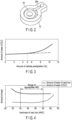
- the roller was incorporated into the compression mechanism part of the rotary compressor together with the same blade as Example 1, and the amount of wear of the DLC film of the blade and the amount of wear of the roller were determined under the same operation condition. The results are shown in FIG. 4 .
- a roller was produced from spheroidal graphite cast iron (JIS G 5502:2001).
- a roller was produced from monichrome cast iron, that is, special alloy cast iron in which Mo, Ni and Cr are added to spheroidal graphite cast iron [JIS G 5501: 1995].
- Example 3 Each of the obtained rollers of Example 3 and Comparative Examples 1 and 2 was incorporated into the refrigerator of the rotary compressor together with the same blade as Example 1, and the amount of wear of the DLC film coating the surface of the substrate of the blade was determined under the same operation condition as Example 1.
- the results are shown in FIG. 5 .
- the wear limit is a value at which the DLC film on the surface of the substrate is worn and the surface of the substrate is exposed.
- a blade was produced by coating the surface of a substrate made of SKH51 and having a Rockwell hardness (HRC) of 63 with a diamond-like carbon film (DLC film) having a Vickers hardness (Hv) of 2500 and having a thickness of 2.5 ⁇ m by the CVD method.
- HRC Rockwell hardness
- DLC film diamond-like carbon film having a Vickers hardness (Hv) of 2500 and having a thickness of 2.5 ⁇ m by the CVD method.
- a blade was produced by nitriding the surface of a substrate made of SUS440C and having a Rockwell hardness (HRC) of 36 to form a nitride film having a Vickers hardness (Hv) of 1000 and having a thickness of 8 ⁇ m.
- HRC Rockwell hardness
- a blade was produced by coating the surface of a substrate made of SKH51 and having a Rockwell hardness (HRC) of 63 with a CrN film having a Vickers hardness (Hv) of 1200 and having a thickness of 2 ⁇ m by the CVD method.
- HRC Rockwell hardness
- Hv Vickers hardness
- Example 4 Each of the obtained blades of Example 4 and Comparative Examples 3 and 4 was incorporated with the same roller as Example 3 into the refrigerator of the rotary compressor in the same manner as Example 1, and the wear resistance of the coating film on the surface of the blade was evaluated under the same operation condition as Example 1.
- Polyol ester oil which is a refrigeration machine oil containing 0%, 0.1%, 0.3%, 0.5%, 0.6%, 0.7%, 0.8%, 0.9% or 1.0% by weight of tricresylphosphate which is an extreme pressure additive was used, and the same blade as Example 1 and a roller made of the same cast iron as Example 1, having an amount of carbide precipitation on a sliding surface with the blade of 2% in area ratio, and having an HRC of 45 were incorporated into the compression mechanism part of the rotary compressor, and the amount of wear of the DLC film of the blade was determined under the same operating condition as Example 1. The results are shown in FIG. 6 .
- the wear of the DLC film of the blade can be suppressed by using polyol ester oil which is a refrigeration machine oil in which the content of tricresylphosphate which is an extreme pressure additive is less than or equal to 0.5% by weight.
- the present invention can provide a sealed compressor capable of ensuring wear resistance even in a sliding environment in which a first member and a second member sliding with each other of a compression mechanism part, for example, a blade and a roller are in a one-sided contact state.
Landscapes
- Chemical & Material Sciences (AREA)
- Engineering & Computer Science (AREA)
- Organic Chemistry (AREA)
- Mechanical Engineering (AREA)
- General Engineering & Computer Science (AREA)
- Materials Engineering (AREA)
- Metallurgy (AREA)
- Physics & Mathematics (AREA)
- Thermal Sciences (AREA)
- Crystallography & Structural Chemistry (AREA)
- Inorganic Chemistry (AREA)
- Applications Or Details Of Rotary Compressors (AREA)
- Heat Treatment Of Articles (AREA)
- Compressor (AREA)
- Chemical Vapour Deposition (AREA)
Applications Claiming Priority (2)
| Application Number | Priority Date | Filing Date | Title |
|---|---|---|---|
| JP2019058928 | 2019-03-26 | ||
| PCT/JP2020/007807 WO2020195490A1 (ja) | 2019-03-26 | 2020-02-26 | 密閉型圧縮機および冷凍サイクル装置 |
Publications (3)
| Publication Number | Publication Date |
|---|---|
| EP3951176A1 EP3951176A1 (en) | 2022-02-09 |
| EP3951176A4 EP3951176A4 (en) | 2022-12-28 |
| EP3951176B1 true EP3951176B1 (en) | 2024-09-04 |
Family
ID=72609209
Family Applications (1)
| Application Number | Title | Priority Date | Filing Date |
|---|---|---|---|
| EP20776408.5A Active EP3951176B1 (en) | 2019-03-26 | 2020-02-26 | Sealed compressor and refrigeration cycle device |
Country Status (4)
| Country | Link |
|---|---|
| EP (1) | EP3951176B1 (https=) |
| JP (2) | JP7171892B2 (https=) |
| CN (1) | CN113646533B (https=) |
| WO (1) | WO2020195490A1 (https=) |
Family Cites Families (19)
| Publication number | Priority date | Publication date | Assignee | Title |
|---|---|---|---|---|
| JPS5113902B2 (https=) | 1972-09-07 | 1976-05-04 | ||
| JPS62253983A (ja) * | 1986-04-28 | 1987-11-05 | Mazda Motor Corp | 回転圧縮機 |
| JPH01125575A (ja) * | 1987-11-06 | 1989-05-18 | Daikin Ind Ltd | シリンダブロック |
| JPH07259772A (ja) * | 1994-03-18 | 1995-10-09 | Nippon Piston Ring Co Ltd | 圧縮機用部材 |
| JPH07293468A (ja) * | 1994-04-28 | 1995-11-07 | Toshiba Corp | 密閉形コンプレッサ |
| JP3722599B2 (ja) * | 1997-09-26 | 2005-11-30 | 日本ピストンリング株式会社 | 回転式圧縮機 |
| JP2000297753A (ja) * | 1999-04-15 | 2000-10-24 | Matsushita Refrig Co Ltd | 密閉型圧縮機 |
| JP3914657B2 (ja) | 1999-05-11 | 2007-05-16 | カヤバ工業株式会社 | ピストンの表面処理方法 |
| JP2004278391A (ja) * | 2003-03-14 | 2004-10-07 | Matsushita Electric Ind Co Ltd | 回転式圧縮機及び冷凍装置 |
| EP1963467B1 (en) * | 2005-12-09 | 2014-03-26 | Council of Scientific & Industrial Research | Process for the preparation of a hydraulic fluid composition |
| JP2007245234A (ja) * | 2006-01-26 | 2007-09-27 | Daikin Ind Ltd | 圧縮機の摺動部品の製造方法および圧縮機 |
| CN101855422B (zh) * | 2007-11-21 | 2012-05-30 | 松下电器产业株式会社 | 膨胀机一体型压缩机 |
| JP2009127532A (ja) | 2007-11-22 | 2009-06-11 | Oume Chuzo Kk | コンプレッサー用ハウジング |
| JP2010101232A (ja) * | 2008-10-23 | 2010-05-06 | Panasonic Corp | 冷媒圧縮機 |
| JP6011861B2 (ja) * | 2010-09-07 | 2016-10-19 | パナソニックIpマネジメント株式会社 | 圧縮機およびそれを用いた冷凍サイクル装置 |
| KR101294671B1 (ko) | 2011-11-14 | 2013-08-09 | 엘지전자 주식회사 | 구상흑연주철 및 그를 이용한 로터리 압축기용 베인의 제조방법 |
| KR101404754B1 (ko) * | 2011-11-14 | 2014-06-13 | 엘지전자 주식회사 | 합금주철 및 그를 이용한 로터리 압축기의 롤링피스톤의 제조방법 |
| JP2017031830A (ja) * | 2015-07-29 | 2017-02-09 | 株式会社富士通ゼネラル | ロータリ圧縮機 |
| JP2017031831A (ja) * | 2015-07-29 | 2017-02-09 | 株式会社富士通ゼネラル | ロータリ圧縮機 |
-
2020
- 2020-02-26 JP JP2021508842A patent/JP7171892B2/ja active Active
- 2020-02-26 EP EP20776408.5A patent/EP3951176B1/en active Active
- 2020-02-26 CN CN202080023834.8A patent/CN113646533B/zh active Active
- 2020-02-26 WO PCT/JP2020/007807 patent/WO2020195490A1/ja not_active Ceased
-
2022
- 2022-10-28 JP JP2022173490A patent/JP7532472B2/ja active Active
Also Published As
| Publication number | Publication date |
|---|---|
| JPWO2020195490A1 (ja) | 2021-12-02 |
| CN113646533A (zh) | 2021-11-12 |
| JP7171892B2 (ja) | 2022-11-15 |
| EP3951176A4 (en) | 2022-12-28 |
| JP7532472B2 (ja) | 2024-08-13 |
| WO2020195490A1 (ja) | 2020-10-01 |
| CN113646533B (zh) | 2023-10-10 |
| EP3951176A1 (en) | 2022-02-09 |
| JP2023017855A (ja) | 2023-02-07 |
Similar Documents
| Publication | Publication Date | Title |
|---|---|---|
| US6547544B2 (en) | Hermetic compressor and open compressor | |
| JP6011861B2 (ja) | 圧縮機およびそれを用いた冷凍サイクル装置 | |
| JPH07293468A (ja) | 密閉形コンプレッサ | |
| JP6740105B2 (ja) | 密閉型圧縮機および冷凍サイクル装置 | |
| US20080025861A1 (en) | Sliding Element and Fluid Machine | |
| EP3951176B1 (en) | Sealed compressor and refrigeration cycle device | |
| JP2005155461A (ja) | 圧縮機 | |
| JP4069839B2 (ja) | 摺動装置とその製造法及び冷媒圧縮機 | |
| US12297832B2 (en) | Compressor with chromium nitride and titanium nitride layers | |
| JP2005155459A (ja) | 圧縮機 | |
| JP2005155460A (ja) | 圧縮機 | |
| US20250376981A1 (en) | Compressor | |
| JPH05106581A (ja) | 冷媒圧縮機 | |
| JP2002202073A (ja) | 揺動ピストン型圧縮機およびこれを用いた冷媒圧縮機並びに空気調和機 | |
| JP2005214038A (ja) | ロータリ圧縮機 | |
| JP2005155458A (ja) | 圧縮機 | |
| JP2000087890A (ja) | ロータリー圧縮機 | |
| JP2005133586A (ja) | 密閉型冷媒圧縮機 | |
| JP2020180618A (ja) | 密閉型圧縮機および冷凍サイクル装置 | |
| JPH05340369A (ja) | 圧縮機 | |
| JP2005048686A (ja) | 冷媒圧縮機 | |
| JPH06117383A (ja) | 密閉型冷媒圧縮機 |
Legal Events
| Date | Code | Title | Description |
|---|---|---|---|
| STAA | Information on the status of an ep patent application or granted ep patent |
Free format text: STATUS: THE INTERNATIONAL PUBLICATION HAS BEEN MADE |
|
| PUAI | Public reference made under article 153(3) epc to a published international application that has entered the european phase |
Free format text: ORIGINAL CODE: 0009012 |
|
| STAA | Information on the status of an ep patent application or granted ep patent |
Free format text: STATUS: REQUEST FOR EXAMINATION WAS MADE |
|
| 17P | Request for examination filed |
Effective date: 20211025 |
|
| AK | Designated contracting states |
Kind code of ref document: A1 Designated state(s): AL AT BE BG CH CY CZ DE DK EE ES FI FR GB GR HR HU IE IS IT LI LT LU LV MC MK MT NL NO PL PT RO RS SE SI SK SM TR |
|
| DAV | Request for validation of the european patent (deleted) | ||
| DAX | Request for extension of the european patent (deleted) | ||
| A4 | Supplementary search report drawn up and despatched |
Effective date: 20221124 |
|
| RIC1 | Information provided on ipc code assigned before grant |
Ipc: C21D 9/00 20060101ALI20221118BHEP Ipc: C21D 1/18 20060101ALI20221118BHEP Ipc: F04C 29/00 20060101ALI20221118BHEP Ipc: F04C 18/356 20060101ALI20221118BHEP Ipc: C22C 38/04 20060101ALI20221118BHEP Ipc: C22C 37/04 20060101ALI20221118BHEP Ipc: C21D 5/00 20060101ALI20221118BHEP Ipc: C01B 32/20 20170101ALI20221118BHEP Ipc: C01B 32/05 20170101ALI20221118BHEP Ipc: F04B 39/00 20060101AFI20221118BHEP |
|
| GRAP | Despatch of communication of intention to grant a patent |
Free format text: ORIGINAL CODE: EPIDOSNIGR1 |
|
| STAA | Information on the status of an ep patent application or granted ep patent |
Free format text: STATUS: GRANT OF PATENT IS INTENDED |
|
| INTG | Intention to grant announced |
Effective date: 20240326 |
|
| GRAS | Grant fee paid |
Free format text: ORIGINAL CODE: EPIDOSNIGR3 |
|
| GRAA | (expected) grant |
Free format text: ORIGINAL CODE: 0009210 |
|
| STAA | Information on the status of an ep patent application or granted ep patent |
Free format text: STATUS: THE PATENT HAS BEEN GRANTED |
|
| AK | Designated contracting states |
Kind code of ref document: B1 Designated state(s): AL AT BE BG CH CY CZ DE DK EE ES FI FR GB GR HR HU IE IS IT LI LT LU LV MC MK MT NL NO PL PT RO RS SE SI SK SM TR |
|
| RAP3 | Party data changed (applicant data changed or rights of an application transferred) |
Owner name: CARRIER JAPAN CORPORATION |
|
| REG | Reference to a national code |
Ref country code: GB Ref legal event code: FG4D |
|
| REG | Reference to a national code |
Ref country code: CH Ref legal event code: EP |
|
| REG | Reference to a national code |
Ref country code: IE Ref legal event code: FG4D |
|
| REG | Reference to a national code |
Ref country code: DE Ref legal event code: R096 Ref document number: 602020037159 Country of ref document: DE |
|
| REG | Reference to a national code |
Ref country code: LT Ref legal event code: MG9D |
|
| REG | Reference to a national code |
Ref country code: NL Ref legal event code: MP Effective date: 20240904 |
|
| PG25 | Lapsed in a contracting state [announced via postgrant information from national office to epo] |
Ref country code: NO Free format text: LAPSE BECAUSE OF FAILURE TO SUBMIT A TRANSLATION OF THE DESCRIPTION OR TO PAY THE FEE WITHIN THE PRESCRIBED TIME-LIMIT Effective date: 20241204 |
|
| PG25 | Lapsed in a contracting state [announced via postgrant information from national office to epo] |
Ref country code: PL Free format text: LAPSE BECAUSE OF FAILURE TO SUBMIT A TRANSLATION OF THE DESCRIPTION OR TO PAY THE FEE WITHIN THE PRESCRIBED TIME-LIMIT Effective date: 20240904 Ref country code: GR Free format text: LAPSE BECAUSE OF FAILURE TO SUBMIT A TRANSLATION OF THE DESCRIPTION OR TO PAY THE FEE WITHIN THE PRESCRIBED TIME-LIMIT Effective date: 20241205 Ref country code: FI Free format text: LAPSE BECAUSE OF FAILURE TO SUBMIT A TRANSLATION OF THE DESCRIPTION OR TO PAY THE FEE WITHIN THE PRESCRIBED TIME-LIMIT Effective date: 20240904 |
|
| PG25 | Lapsed in a contracting state [announced via postgrant information from national office to epo] |
Ref country code: BG Free format text: LAPSE BECAUSE OF FAILURE TO SUBMIT A TRANSLATION OF THE DESCRIPTION OR TO PAY THE FEE WITHIN THE PRESCRIBED TIME-LIMIT Effective date: 20240904 |
|
| PG25 | Lapsed in a contracting state [announced via postgrant information from national office to epo] |
Ref country code: LV Free format text: LAPSE BECAUSE OF FAILURE TO SUBMIT A TRANSLATION OF THE DESCRIPTION OR TO PAY THE FEE WITHIN THE PRESCRIBED TIME-LIMIT Effective date: 20240904 |
|
| PG25 | Lapsed in a contracting state [announced via postgrant information from national office to epo] |
Ref country code: HR Free format text: LAPSE BECAUSE OF FAILURE TO SUBMIT A TRANSLATION OF THE DESCRIPTION OR TO PAY THE FEE WITHIN THE PRESCRIBED TIME-LIMIT Effective date: 20240904 |
|
| PG25 | Lapsed in a contracting state [announced via postgrant information from national office to epo] |
Ref country code: ES Free format text: LAPSE BECAUSE OF FAILURE TO SUBMIT A TRANSLATION OF THE DESCRIPTION OR TO PAY THE FEE WITHIN THE PRESCRIBED TIME-LIMIT Effective date: 20240904 Ref country code: RS Free format text: LAPSE BECAUSE OF FAILURE TO SUBMIT A TRANSLATION OF THE DESCRIPTION OR TO PAY THE FEE WITHIN THE PRESCRIBED TIME-LIMIT Effective date: 20241204 |
|
| PG25 | Lapsed in a contracting state [announced via postgrant information from national office to epo] |
Ref country code: RS Free format text: LAPSE BECAUSE OF FAILURE TO SUBMIT A TRANSLATION OF THE DESCRIPTION OR TO PAY THE FEE WITHIN THE PRESCRIBED TIME-LIMIT Effective date: 20241204 Ref country code: PL Free format text: LAPSE BECAUSE OF FAILURE TO SUBMIT A TRANSLATION OF THE DESCRIPTION OR TO PAY THE FEE WITHIN THE PRESCRIBED TIME-LIMIT Effective date: 20240904 Ref country code: NO Free format text: LAPSE BECAUSE OF FAILURE TO SUBMIT A TRANSLATION OF THE DESCRIPTION OR TO PAY THE FEE WITHIN THE PRESCRIBED TIME-LIMIT Effective date: 20241204 Ref country code: LV Free format text: LAPSE BECAUSE OF FAILURE TO SUBMIT A TRANSLATION OF THE DESCRIPTION OR TO PAY THE FEE WITHIN THE PRESCRIBED TIME-LIMIT Effective date: 20240904 Ref country code: HR Free format text: LAPSE BECAUSE OF FAILURE TO SUBMIT A TRANSLATION OF THE DESCRIPTION OR TO PAY THE FEE WITHIN THE PRESCRIBED TIME-LIMIT Effective date: 20240904 Ref country code: GR Free format text: LAPSE BECAUSE OF FAILURE TO SUBMIT A TRANSLATION OF THE DESCRIPTION OR TO PAY THE FEE WITHIN THE PRESCRIBED TIME-LIMIT Effective date: 20241205 Ref country code: FI Free format text: LAPSE BECAUSE OF FAILURE TO SUBMIT A TRANSLATION OF THE DESCRIPTION OR TO PAY THE FEE WITHIN THE PRESCRIBED TIME-LIMIT Effective date: 20240904 Ref country code: ES Free format text: LAPSE BECAUSE OF FAILURE TO SUBMIT A TRANSLATION OF THE DESCRIPTION OR TO PAY THE FEE WITHIN THE PRESCRIBED TIME-LIMIT Effective date: 20240904 Ref country code: BG Free format text: LAPSE BECAUSE OF FAILURE TO SUBMIT A TRANSLATION OF THE DESCRIPTION OR TO PAY THE FEE WITHIN THE PRESCRIBED TIME-LIMIT Effective date: 20240904 |
|
| REG | Reference to a national code |
Ref country code: AT Ref legal event code: MK05 Ref document number: 1720651 Country of ref document: AT Kind code of ref document: T Effective date: 20240904 |
|
| PG25 | Lapsed in a contracting state [announced via postgrant information from national office to epo] |
Ref country code: NL Free format text: LAPSE BECAUSE OF FAILURE TO SUBMIT A TRANSLATION OF THE DESCRIPTION OR TO PAY THE FEE WITHIN THE PRESCRIBED TIME-LIMIT Effective date: 20240904 |
|
| PG25 | Lapsed in a contracting state [announced via postgrant information from national office to epo] |
Ref country code: PT Free format text: LAPSE BECAUSE OF FAILURE TO SUBMIT A TRANSLATION OF THE DESCRIPTION OR TO PAY THE FEE WITHIN THE PRESCRIBED TIME-LIMIT Effective date: 20250106 Ref country code: IS Free format text: LAPSE BECAUSE OF FAILURE TO SUBMIT A TRANSLATION OF THE DESCRIPTION OR TO PAY THE FEE WITHIN THE PRESCRIBED TIME-LIMIT Effective date: 20250104 |
|
| PG25 | Lapsed in a contracting state [announced via postgrant information from national office to epo] |
Ref country code: SM Free format text: LAPSE BECAUSE OF FAILURE TO SUBMIT A TRANSLATION OF THE DESCRIPTION OR TO PAY THE FEE WITHIN THE PRESCRIBED TIME-LIMIT Effective date: 20240904 Ref country code: RO Free format text: LAPSE BECAUSE OF FAILURE TO SUBMIT A TRANSLATION OF THE DESCRIPTION OR TO PAY THE FEE WITHIN THE PRESCRIBED TIME-LIMIT Effective date: 20240904 |
|
| PG25 | Lapsed in a contracting state [announced via postgrant information from national office to epo] |
Ref country code: EE Free format text: LAPSE BECAUSE OF FAILURE TO SUBMIT A TRANSLATION OF THE DESCRIPTION OR TO PAY THE FEE WITHIN THE PRESCRIBED TIME-LIMIT Effective date: 20240904 Ref country code: AT Free format text: LAPSE BECAUSE OF FAILURE TO SUBMIT A TRANSLATION OF THE DESCRIPTION OR TO PAY THE FEE WITHIN THE PRESCRIBED TIME-LIMIT Effective date: 20240904 |
|
| PG25 | Lapsed in a contracting state [announced via postgrant information from national office to epo] |
Ref country code: CZ Free format text: LAPSE BECAUSE OF FAILURE TO SUBMIT A TRANSLATION OF THE DESCRIPTION OR TO PAY THE FEE WITHIN THE PRESCRIBED TIME-LIMIT Effective date: 20240904 |
|
| PG25 | Lapsed in a contracting state [announced via postgrant information from national office to epo] |
Ref country code: SK Free format text: LAPSE BECAUSE OF FAILURE TO SUBMIT A TRANSLATION OF THE DESCRIPTION OR TO PAY THE FEE WITHIN THE PRESCRIBED TIME-LIMIT Effective date: 20240904 |
|
| REG | Reference to a national code |
Ref country code: DE Ref legal event code: R097 Ref document number: 602020037159 Country of ref document: DE |
|
| PG25 | Lapsed in a contracting state [announced via postgrant information from national office to epo] |
Ref country code: DK Free format text: LAPSE BECAUSE OF FAILURE TO SUBMIT A TRANSLATION OF THE DESCRIPTION OR TO PAY THE FEE WITHIN THE PRESCRIBED TIME-LIMIT Effective date: 20240904 |
|
| PLBE | No opposition filed within time limit |
Free format text: ORIGINAL CODE: 0009261 |
|
| STAA | Information on the status of an ep patent application or granted ep patent |
Free format text: STATUS: NO OPPOSITION FILED WITHIN TIME LIMIT |
|
| 26N | No opposition filed |
Effective date: 20250605 |
|
| PG25 | Lapsed in a contracting state [announced via postgrant information from national office to epo] |
Ref country code: SE Free format text: LAPSE BECAUSE OF FAILURE TO SUBMIT A TRANSLATION OF THE DESCRIPTION OR TO PAY THE FEE WITHIN THE PRESCRIBED TIME-LIMIT Effective date: 20240904 |
|
| PG25 | Lapsed in a contracting state [announced via postgrant information from national office to epo] |
Ref country code: MC Free format text: LAPSE BECAUSE OF FAILURE TO SUBMIT A TRANSLATION OF THE DESCRIPTION OR TO PAY THE FEE WITHIN THE PRESCRIBED TIME-LIMIT Effective date: 20240904 |
|
| REG | Reference to a national code |
Ref country code: CH Ref legal event code: PL |
|
| PG25 | Lapsed in a contracting state [announced via postgrant information from national office to epo] |
Ref country code: LU Free format text: LAPSE BECAUSE OF NON-PAYMENT OF DUE FEES Effective date: 20250226 |
|
| PG25 | Lapsed in a contracting state [announced via postgrant information from national office to epo] |
Ref country code: CH Free format text: LAPSE BECAUSE OF NON-PAYMENT OF DUE FEES Effective date: 20250228 |
|
| REG | Reference to a national code |
Ref country code: BE Ref legal event code: MM Effective date: 20250228 |
|
| PG25 | Lapsed in a contracting state [announced via postgrant information from national office to epo] |
Ref country code: IT Free format text: LAPSE BECAUSE OF NON-PAYMENT OF DUE FEES Effective date: 20250226 |
|
| PG25 | Lapsed in a contracting state [announced via postgrant information from national office to epo] |
Ref country code: BE Free format text: LAPSE BECAUSE OF NON-PAYMENT OF DUE FEES Effective date: 20250228 |
|
| PG25 | Lapsed in a contracting state [announced via postgrant information from national office to epo] |
Ref country code: IE Free format text: LAPSE BECAUSE OF NON-PAYMENT OF DUE FEES Effective date: 20250226 |
|
| PGFP | Annual fee paid to national office [announced via postgrant information from national office to epo] |
Ref country code: GB Payment date: 20260121 Year of fee payment: 7 |
|
| PGFP | Annual fee paid to national office [announced via postgrant information from national office to epo] |
Ref country code: DE Payment date: 20260121 Year of fee payment: 7 |
|
| PGFP | Annual fee paid to national office [announced via postgrant information from national office to epo] |
Ref country code: FR Payment date: 20260121 Year of fee payment: 7 |