EP3950191B1 - Spannfutter mit staubdichtem mechanismus - Google Patents
Spannfutter mit staubdichtem mechanismus Download PDFInfo
- Publication number
- EP3950191B1 EP3950191B1 EP20776545.4A EP20776545A EP3950191B1 EP 3950191 B1 EP3950191 B1 EP 3950191B1 EP 20776545 A EP20776545 A EP 20776545A EP 3950191 B1 EP3950191 B1 EP 3950191B1
- Authority
- EP
- European Patent Office
- Prior art keywords
- chuck
- supply
- gap
- master jaw
- dust
- Prior art date
- Legal status (The legal status is an assumption and is not a legal conclusion. Google has not performed a legal analysis and makes no representation as to the accuracy of the status listed.)
- Active
Links
Images



Classifications
-
- B—PERFORMING OPERATIONS; TRANSPORTING
- B23—MACHINE TOOLS; METAL-WORKING NOT OTHERWISE PROVIDED FOR
- B23B—TURNING; BORING
- B23B31/00—Chucks; Expansion mandrels; Adaptations thereof for remote control
- B23B31/001—Protection against entering of chips or dust
-
- B—PERFORMING OPERATIONS; TRANSPORTING
- B23—MACHINE TOOLS; METAL-WORKING NOT OTHERWISE PROVIDED FOR
- B23B—TURNING; BORING
- B23B31/00—Chucks; Expansion mandrels; Adaptations thereof for remote control
- B23B31/02—Chucks
- B23B31/10—Chucks characterised by the retaining or gripping devices or their immediate operating means
- B23B31/12—Chucks with simultaneously-acting jaws, whether or not also individually adjustable
- B23B31/16—Chucks with simultaneously-acting jaws, whether or not also individually adjustable moving radially
- B23B31/16233—Jaws movement actuated by oblique surfaces of a coaxial control rod
- B23B31/16254—Jaws movement actuated by oblique surfaces of a coaxial control rod using fluid-pressure means to actuate the gripping means
-
- B—PERFORMING OPERATIONS; TRANSPORTING
- B23—MACHINE TOOLS; METAL-WORKING NOT OTHERWISE PROVIDED FOR
- B23Q—DETAILS, COMPONENTS, OR ACCESSORIES FOR MACHINE TOOLS, e.g. ARRANGEMENTS FOR COPYING OR CONTROLLING; MACHINE TOOLS IN GENERAL CHARACTERISED BY THE CONSTRUCTION OF PARTICULAR DETAILS OR COMPONENTS; COMBINATIONS OR ASSOCIATIONS OF METAL-WORKING MACHINES, NOT DIRECTED TO A PARTICULAR RESULT
- B23Q11/00—Accessories fitted to machine tools for keeping tools or parts of the machine in good working condition or for cooling work; Safety devices specially combined with or arranged in, or specially adapted for use in connection with, machine tools
- B23Q11/08—Protective coverings for parts of machine tools; Splash guards
-
- B—PERFORMING OPERATIONS; TRANSPORTING
- B23—MACHINE TOOLS; METAL-WORKING NOT OTHERWISE PROVIDED FOR
- B23Q—DETAILS, COMPONENTS, OR ACCESSORIES FOR MACHINE TOOLS, e.g. ARRANGEMENTS FOR COPYING OR CONTROLLING; MACHINE TOOLS IN GENERAL CHARACTERISED BY THE CONSTRUCTION OF PARTICULAR DETAILS OR COMPONENTS; COMBINATIONS OR ASSOCIATIONS OF METAL-WORKING MACHINES, NOT DIRECTED TO A PARTICULAR RESULT
- B23Q11/00—Accessories fitted to machine tools for keeping tools or parts of the machine in good working condition or for cooling work; Safety devices specially combined with or arranged in, or specially adapted for use in connection with, machine tools
- B23Q11/12—Arrangements for cooling or lubricating parts of the machine
-
- B—PERFORMING OPERATIONS; TRANSPORTING
- B23—MACHINE TOOLS; METAL-WORKING NOT OTHERWISE PROVIDED FOR
- B23B—TURNING; BORING
- B23B2231/00—Details of chucks, toolholder shanks or tool shanks
- B23B2231/24—Cooling or lubrication means
-
- B—PERFORMING OPERATIONS; TRANSPORTING
- B23—MACHINE TOOLS; METAL-WORKING NOT OTHERWISE PROVIDED FOR
- B23B—TURNING; BORING
- B23B2231/00—Details of chucks, toolholder shanks or tool shanks
- B23B2231/28—Dust covers
-
- B—PERFORMING OPERATIONS; TRANSPORTING
- B23—MACHINE TOOLS; METAL-WORKING NOT OTHERWISE PROVIDED FOR
- B23B—TURNING; BORING
- B23B2231/00—Details of chucks, toolholder shanks or tool shanks
- B23B2231/36—Sealed joints
- B23B2231/365—Sealed joints using O-rings
-
- B—PERFORMING OPERATIONS; TRANSPORTING
- B23—MACHINE TOOLS; METAL-WORKING NOT OTHERWISE PROVIDED FOR
- B23B—TURNING; BORING
- B23B2260/00—Details of constructional elements
- B23B2260/058—Dust covers
-
- Y—GENERAL TAGGING OF NEW TECHNOLOGICAL DEVELOPMENTS; GENERAL TAGGING OF CROSS-SECTIONAL TECHNOLOGIES SPANNING OVER SEVERAL SECTIONS OF THE IPC; TECHNICAL SUBJECTS COVERED BY FORMER USPC CROSS-REFERENCE ART COLLECTIONS [XRACs] AND DIGESTS
- Y10—TECHNICAL SUBJECTS COVERED BY FORMER USPC
- Y10T—TECHNICAL SUBJECTS COVERED BY FORMER US CLASSIFICATION
- Y10T279/00—Chucks or sockets
- Y10T279/34—Accessory or component
- Y10T279/3493—Protection means; e.g., cover, seal, overstress prevention, air blast
Definitions
- the present invention relates to a chuck having a dust-proof mechanism for preventing the entry of foreign matter into the chuck.
- a prior art chuck is known from document WO 2018/092797 A1 which discloses a chuck comprising a dust-proof mechanism for preventing the entry of foreign matter into the chuck, the dust-proof mechanism comprising a fluid supply source, an inner space that is provided in the chuck and through which a supply fluid supplied from the fluid supply source can pass as a pressurized fluid and a discharge clearance that is provided in the chuck and through which the pressurized fluid can be discharged to outside of the chuck from the inner space.
- a chuck is provided therein with an action mechanism for moving claws of the chuck.
- an action mechanism for moving claws of the chuck There are known dust-proof mechanisms which do not adversely impact the chuck action due to chips, cutting oil, or the like entering the chuck.
- Patent Literature 1 when a problem occurs in the spring member, it becomes difficult for the dust-proof plate to close a gap between the base jaw and the notch of the cover plate. In this case, foreign matter such as chips or cutting oil might have possibly entered the inside of the chuck main body through the gap. Moreover, in Patent Literature 2, the high-pressure coolant might have possibly pushed dust such as chips into the gap between the chuck main body and the jaw.
- the present invention provides a chuck as defined in independent claim 1.
- the present invention is able to prevent the entry of foreign matter into the chuck.
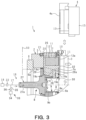
- a chuck 1 is fixed to a main axis 50 ( Fig. 3 ) of a machine tool such as an NC lathe.
- the chuck 1 includes a chuck main body 2, a master jaw 7 provided at the chuck main body 2, and a drive member 8 provided inside the chuck main body 2.
- the chuck main body 2 includes attachment grooves 3 extending in a radial direction, so that a work W is clamped by claws 4 attached on the attachment groove 3.
- the work W is conveyed to the chuck 1 by a loader 51 exemplified as a conveyance device.
- the work W clamped by the chuck 1 is processed by forward/backward/rightward/leftward movement of a tool rest (not illustrated) with a plurality of cutting tools.
- the claw 4 is replaced manually or with a claw automatic replacement device (not illustrated) when the diameter of the work W to be processed is changed or wear has occurred due to a long-time use.
- the chuck main body 2 includes a front body 5 and a rear body 6 provided on the rear end surface of the front body 5 by a mounting bolt (not illustrated).
- a plurality of (three, for example) attachment grooves 3 are provided on the front surface of the front body 5.
- the attachment grooves 3 are arranged in a circumferential direction with the same intervals.
- the front body 5 includes a cylindrical first inner peripheral surface 5a and a cylindrical second inner peripheral surface 5b.
- the first inner peripheral surface 5a is provided on the rear side
- the second inner peripheral surface 5b is provided on the front side.
- the diameter of the second inner peripheral surface 5b is smaller than the diameter of the first inner peripheral surface 5a.
- the front side indicates the side where the claw 4 can be attached, while the rear side indicates the side of the main axis 50 of the machine tool.
- the master jaw 7 is arranged in each guide groove 25 of the front body 5.
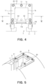
- the guide groove 25 is arranged to correspond to the above-described attachment groove 3, and extends in a radial direction. As illustrated in Fig. 3 and Fig. 4 , each guide groove 25 forms a space continuous to the corresponding attachment groove 3.
- the master jaw 7 is movable in a radial direction in the guide groove 25.
- the claw 4 includes a base jaw 13, and a top jaw 15 fixed on the front surface of the base jaw 13 by a plurality of bolts 14.
- the base jaw 13 is inserted in the attachment groove 3.
- the attachment groove 3 is formed in front of the master jaw 7 inserted in the guide groove 25.
- the connection surface 4a is provided on the rear surface of the base jaw 13.
- the drive member 8 drives the master jaw 7.
- the drive member 8 includes a draw screw 27, a wedge plunger 28, and a retainer 29.
- the draw screw 27, the wedge plunger 28, and the retainer 29 are integrally movable along a center axis line CL.
- the draw screw 27 is arranged with the center axis line CL of the chuck main body 2 as a center.
- the wedge plunger 28 is attached on the front surface of the draw screw 27.
- the wedge plunger 28 includes a wedge engagement groove 28a, and a wedge portion 7a of the master jaw 7 is engaged with the wedge engagement groove 28a. In this manner, the draw screw 27 meshes with each master jaw 7 through the wedge plunger 28.
- the wedge engagement groove 28a is inclined relative to the center axis line CL.
- the drive member 8 advances (moves rightward in Fig. 3 ) or retreats (moves leftward in Fig. 3 , see Fig. 7 ) along the center axis line CL, whereby each master jaw 7 is moved in the radial direction along the guide groove 25. That is, as illustrated in Fig. 3 , when the drive member 8 advances, each master jaw 7 moves outward in the radial direction. Meanwhile, as illustrated in Fig. 7 , when the drive member 8 is retreated, each master jaw 7 moves inward in the radial direction.
- the drive guide member 9 (also referred to as a pilot bushing) is provided inside the front body 5.
- the drive guide member 9 is configured to guide the movement of the drive member 8.
- the drive guide member 9 includes a cylindrical part 9a, and a rear edge portion 9b provided at the rear end part of the cylindrical part 9a.
- the cylindrical part 9a is formed concentrically with the center axis line CL.
- the front edge portion of the cylindrical part 9a is attached on the second inner peripheral surface 5b of the front body 5.
- the outer peripheral surface of the cylindrical part 9a is a guide surface for guiding the movement of the wedge plunger 28 attached on the drive member 8.
- the rear edge portion 9b is formed perpendicularly to the center axis line CL, and faces the front surface of the drive member 8.
- An outer space B is formed inside the cylindrical part 9a.
- the outer space B is open on the front surface of the chuck main body 2. When the claw 4 clamps the work W, a part of the work W can be inserted in the outer space B.
- a first cover member 30 is attached on the front surface of each master jaw 7.
- the first cover member 30 extends inward in the radial direction from the corresponding master jaw 7 over the cylindrical part 9a of the drive guide member 9.
- a second cover member 31 is attached between the first cover members 30 adjacent to each other in the circumferential direction.
- the first cover member 30 and the second cover member 31 cover a gap between the end portion on the inner side in the radial direction of the master jaw 7 and the front body 5, and a gap between the front body 5 and the cylindrical part 9a of the drive guide member 9. This prevents therefore the entry of foreign matter such as chips and cutting oil into these gaps.
- the above-described outer space B is open on the inner side in the radial direction of the first cover member 30 and the second cover member 31.
- a lubricant stored in a lubricant storing part not illustrated is supplied to the supply pipe 17 by the lubricant supply pump 34, and mixed into supply air in the form of a mist.
- the supply air to which a lubricant is mixed is supplied to the inner space A, and pressurized.
- a distributing valve 36 exemplified as a mixing amount adjusting part may be attached to the mixing pipe 35.
- the distributing valve 36 adjusts a mixing amount of a lubricant to be mixed into supply air to be supplied to the inner space A of the chuck 1.
- the distributing valve 36 may be controlled by a control device (not illustrated) when the claw 4 is replaced by a claw automatic replacement device. Alternatively, the distributing valve 36 may be operated manually when the claw 4 is replaced manually.
- supply air supplied to the inner space A from the air supply source 18 is pressurized, and the pressurized air in the inner space A passes the discharge clearance 32 to be discharged to the outside of the chuck 1 from the inner space A.
- the pressurized air is discharged to the outside from the inner space A through the discharge clearance 32, which enables simplification of the configuration of the air supply flow path. In this manner, it is possible to prevent the entry of foreign matter with a simple configuration.
Landscapes
- Engineering & Computer Science (AREA)
- Mechanical Engineering (AREA)
- Gripping On Spindles (AREA)
- Auxiliary Devices For Machine Tools (AREA)
Claims (7)
- Spannfutter (1), umfassend:einen Staubschutzmechanismus (16) zur Verhinderung des Eindringens von Fremdkörpern in das Spannfutter (1), wobeider Staubschutzmechanismus (16) umfasst:eine Fluidversorgungsquelle (18);einen Innenraum (A), der im Spannfutter (1) vorgesehen ist und durch den ein von der Fluidversorgungsquelle (18) zugeführtes Fluid unter Druck nach außen strömen kann;einen Auslassspalt (32), der im Spannfutter (1) vorgesehen ist und durch den das unter Druck stehende Fluid aus dem Innenraum (A) nach außen abgeführt werden kann;wobei der Auslassspalt (32) ein Spalt zwischen einer radial verlaufenden Führungsnut (25), die im Spannfutterkörper (2) des Spannfutters (1) vorgesehen ist, und einer in die Führungsnut (25) eingesetzten Hauptbacke (7) ist; wobei der Spalt an einer Seitenoberfläche, an der eine Klaue (4) befestigt ist, in dem Spalt zwischen der Führungsnut (25) und der Hauptbacke (7) offen ist; wobeider Staubschutzmechanismus (16) außerdem ein zweites Dichtungselement (20) umfasst, das den Spalt zwischen der Hauptbacke (7) und der Führungsnut (25) in der radialen Richtung von außen abdeckt.
- Spannfutter (1) nach Anspruch 1, das außerdem einen durchdringenden Strömungskanal (27a) umfasst, der die Fluidquelle (18) mit dem Innenraum (A) verbindet und ein Antriebselement (8) durchdringt, das die Hauptbacke (7) des Spannfutters (1) antreibt.
- Spannfutter (1) nach Anspruch 2, wobei der durchdringende Strömungskanal (27a) sich entlang einer Mittelachse (CL) des Spannfutters (1) erstreckt.
- Spannfutter (1) nach einem der Ansprüche 1 bis 3, das außerdem ein erstes Dichtungselement (19a bis 19d) umfasst, das in einem anderen Spalt als dem Auslassspalt (32) des Spannfutters (1) angeordnet ist.
- Spannfutter (1) nach einem der vorhergehenden Ansprüche, das außerdem ein Fördermengen-Einstellteil (22) umfasst, das eine Fördermenge der Förderflüssigkeit einstellt.
- Spannfutter (1) nach einem der vorhergehenden Ansprüche, das außerdem ein Mischteil (32) umfasst, an dem ein Schmiermittel in die Förderflüssigkeit eingemischt wird.
- Spannfutter (1) nach Anspruch 6, wobei das Mischteil (32) ein Mischmengen-Einstellteil (36) umfasst, das die Mischmenge eines in die Förderflüssigkeit eingemischten Schmiermittels einstellt.
Applications Claiming Priority (2)
| Application Number | Priority Date | Filing Date | Title |
|---|---|---|---|
| JP2019061767 | 2019-03-27 | ||
| PCT/JP2020/013212 WO2020196582A1 (ja) | 2019-03-27 | 2020-03-25 | チャックの防塵機構およびチャック |
Publications (3)
| Publication Number | Publication Date |
|---|---|
| EP3950191A1 EP3950191A1 (de) | 2022-02-09 |
| EP3950191A4 EP3950191A4 (de) | 2022-12-07 |
| EP3950191B1 true EP3950191B1 (de) | 2025-07-02 |
Family
ID=72612018
Family Applications (1)
| Application Number | Title | Priority Date | Filing Date |
|---|---|---|---|
| EP20776545.4A Active EP3950191B1 (de) | 2019-03-27 | 2020-03-25 | Spannfutter mit staubdichtem mechanismus |
Country Status (7)
| Country | Link |
|---|---|
| US (1) | US20220184712A1 (de) |
| EP (1) | EP3950191B1 (de) |
| JP (1) | JP6849155B2 (de) |
| KR (1) | KR102579143B1 (de) |
| CN (1) | CN113613818B (de) |
| TW (1) | TWI737241B (de) |
| WO (1) | WO2020196582A1 (de) |
Families Citing this family (4)
| Publication number | Priority date | Publication date | Assignee | Title |
|---|---|---|---|---|
| KR102507946B1 (ko) * | 2018-08-10 | 2023-03-09 | 호와고교 가부시키가이샤 | 척의 움켜잡기 정밀도 확인 방법, 척의 발톱 교환 방법 및 척의 움켜잡기 정밀도 확인 장치 |
| US11548076B2 (en) * | 2019-07-25 | 2023-01-10 | Pratt & Whitney Canada Corp. | Chuck for machine tool and sealing system |
| JP2024002119A (ja) * | 2022-06-23 | 2024-01-11 | 株式会社Fuji | ワーク挟持装置、及び工作機械 |
| WO2025205478A1 (ja) * | 2024-03-25 | 2025-10-02 | 株式会社北川鉄工所 | チャック |
Family Cites Families (29)
| Publication number | Priority date | Publication date | Assignee | Title |
|---|---|---|---|---|
| JPS5810166B2 (ja) * | 1980-06-10 | 1983-02-24 | ファナック株式会社 | 清浄機能付き把持装置 |
| DE3524036A1 (de) * | 1985-07-05 | 1987-01-08 | Heinrich Dipl Phys Quarder | Verschmutzungsschutz fuer bohrfutter |
| JPH0115452Y2 (de) * | 1985-11-06 | 1989-05-09 | ||
| JPH0529091Y2 (de) * | 1987-04-08 | 1993-07-26 | ||
| JPH071208Y2 (ja) * | 1988-04-20 | 1995-01-18 | 富士機械製造株式会社 | ワーク保持装置 |
| JP2519176Y2 (ja) | 1991-06-05 | 1996-12-04 | 豊和工業株式会社 | クイックチェンジチャックの防塵装置 |
| JP3687866B2 (ja) * | 1995-12-26 | 2005-08-24 | 本田技研工業株式会社 | 内径把持装置の異物除去装置および異物除去方法 |
| JPH11235632A (ja) * | 1998-02-19 | 1999-08-31 | Toyota Motor Corp | ワークの位置決め固定装置 |
| JP2001277012A (ja) * | 2000-03-31 | 2001-10-09 | Howa Mach Ltd | チャック |
| TW585146U (en) * | 2001-02-06 | 2004-04-21 | Chandox Prec Ind Co Ltd | Improved structure for vertical hydraulic chuck |
| JP2004009151A (ja) * | 2002-06-03 | 2004-01-15 | Smc Corp | 3方向開閉チャック |
| KR20060037336A (ko) * | 2003-07-25 | 2006-05-03 | 가부시키가이샤 코스멕 | 클램프 장치 |
| DE102007034117B4 (de) * | 2007-07-21 | 2011-03-10 | Ab Skf | Schmiervorrichtung |
| WO2009093563A1 (ja) * | 2008-01-24 | 2009-07-30 | Kosmek Ltd. | クランプ装置 |
| JP5257999B2 (ja) * | 2010-05-31 | 2013-08-07 | 春男 竹好 | チャックにおける把持面の切粉付着防止装置 |
| CN201931322U (zh) * | 2010-12-15 | 2011-08-17 | 嘉兴永佳精密机械制造有限公司 | 一种新型强力夹头的防尘机构 |
| JP2012135846A (ja) * | 2010-12-27 | 2012-07-19 | Honda Motor Co Ltd | チャック構造 |
| TWM423762U (en) * | 2011-10-07 | 2012-03-01 | Dar Harnq Industry Co Ltd | Dustproof spindle device |
| CN202667680U (zh) * | 2012-06-10 | 2013-01-16 | 富阳孙氏机床有限公司 | 用于主轴的多道防尘机构 |
| JP5827602B2 (ja) * | 2012-06-28 | 2015-12-02 | 株式会社コスメック | クランプ装置 |
| KR101495888B1 (ko) * | 2014-11-03 | 2015-03-02 | 유학현 | 에어 블로 중공형 핑거 척 |
| CN205128959U (zh) * | 2015-11-10 | 2016-04-06 | 呼和浩特众环(集团)有限责任公司 | 新型楔式动力卡盘 |
| KR102133361B1 (ko) * | 2016-11-15 | 2020-07-13 | 신세테크 가부시키가이샤 | 절삭부스러기·분진 방지커버、절삭부스러기·분진 방지커버세트、척기구 및 공작기계 |
| TWI749105B (zh) * | 2016-11-17 | 2021-12-11 | 日商北川鐵工所股份有限公司 | 卡盤 |
| IT201700014495A1 (it) | 2017-02-09 | 2018-08-09 | Ali Group Srl Carpigiani | Macchina per la produzione e l'erogazione di prodotti liquidi o semiliquidi. |
| JP7167474B2 (ja) * | 2017-04-19 | 2022-11-09 | 豊和工業株式会社 | チャックの部品交換装置 |
| JP7068629B2 (ja) * | 2018-04-27 | 2022-05-17 | 豊和工業株式会社 | 揺動式チャックのシール構造 |
| JP7327771B2 (ja) * | 2018-10-16 | 2023-08-16 | 有限会社 シンセテック | チャック機構、爪装着アダプタ、及び切粉・粉塵防止カバー |
| CN209918921U (zh) * | 2019-04-23 | 2020-01-10 | 浙江京速机床附件有限公司 | 一种内藏式卡盘 |
-
2020
- 2020-03-25 WO PCT/JP2020/013212 patent/WO2020196582A1/ja not_active Ceased
- 2020-03-25 JP JP2020547031A patent/JP6849155B2/ja active Active
- 2020-03-25 EP EP20776545.4A patent/EP3950191B1/de active Active
- 2020-03-25 KR KR1020217029576A patent/KR102579143B1/ko active Active
- 2020-03-25 CN CN202080023642.7A patent/CN113613818B/zh active Active
- 2020-03-25 US US17/598,415 patent/US20220184712A1/en not_active Abandoned
- 2020-03-26 TW TW109110305A patent/TWI737241B/zh active
Also Published As
| Publication number | Publication date |
|---|---|
| TW202042940A (zh) | 2020-12-01 |
| US20220184712A1 (en) | 2022-06-16 |
| EP3950191A4 (de) | 2022-12-07 |
| TWI737241B (zh) | 2021-08-21 |
| WO2020196582A1 (ja) | 2020-10-01 |
| JP6849155B2 (ja) | 2021-03-24 |
| CN113613818A (zh) | 2021-11-05 |
| CN113613818B (zh) | 2024-05-17 |
| KR20210125571A (ko) | 2021-10-18 |
| KR102579143B1 (ko) | 2023-09-18 |
| JPWO2020196582A1 (ja) | 2021-04-08 |
| EP3950191A1 (de) | 2022-02-09 |
Similar Documents
| Publication | Publication Date | Title |
|---|---|---|
| EP3950191B1 (de) | Spannfutter mit staubdichtem mechanismus | |
| EP1841555B2 (de) | Schneidwerkzeug mit kühlanordnung | |
| US4951578A (en) | Tool-mounting assembly | |
| CN103429373B (zh) | 具有用于将刀具流体冲洗在刀片上的喷嘴的、用于内部切屑切削加工的装置 | |
| US10130997B2 (en) | Main shaft device and machine tool provided with same | |
| CN102189440A (zh) | 加工装置 | |
| US11919095B2 (en) | Lathe | |
| US20150251286A1 (en) | Rotation table | |
| US20140197608A1 (en) | Tool holder and tool arrangement | |
| JP6017898B2 (ja) | クランプ装置 | |
| US20170043439A1 (en) | Vibration suppression method for suppressing vibration of object to be processed, and machine processing system | |
| US6601856B2 (en) | Method and device for the dynamic lubrication of a power chuck | |
| US20050045638A1 (en) | Dust intrusion preventing device | |
| KR102134486B1 (ko) | 공작기계의 주축 관통 쿨런트 및 에어 공급장치 | |
| EP1211019B1 (de) | Vorrichtung zum zuführen von kühlmittel einer werkzeugmaschine | |
| KR102634801B1 (ko) | 자동 공구 교환 장치 | |
| US20050036845A1 (en) | Machining apparatus with coolant-operated clamp device | |
| KR101682125B1 (ko) | 공작물 장착용 척 구조체 | |
| JP2020066114A (ja) | チャックユニット | |
| JP2022177871A (ja) | チャック装置 | |
| JP4530677B2 (ja) | 工作機械用工具ホルダ | |
| KR20150102772A (ko) | 공작기계용 도어 구동장치 | |
| KR20110071263A (ko) | 절삭유 공급 조립체 | |
| US8893595B2 (en) | Chuck device having two collets | |
| EP0988927A2 (de) | Verfahren zum Bearbeiten eines Werkstücks und Vorrichtung zur Erzeugung von darin verwendetem Nebel |
Legal Events
| Date | Code | Title | Description |
|---|---|---|---|
| STAA | Information on the status of an ep patent application or granted ep patent |
Free format text: STATUS: THE INTERNATIONAL PUBLICATION HAS BEEN MADE |
|
| PUAI | Public reference made under article 153(3) epc to a published international application that has entered the european phase |
Free format text: ORIGINAL CODE: 0009012 |
|
| STAA | Information on the status of an ep patent application or granted ep patent |
Free format text: STATUS: REQUEST FOR EXAMINATION WAS MADE |
|
| 17P | Request for examination filed |
Effective date: 20210906 |
|
| AK | Designated contracting states |
Kind code of ref document: A1 Designated state(s): AL AT BE BG CH CY CZ DE DK EE ES FI FR GB GR HR HU IE IS IT LI LT LU LV MC MK MT NL NO PL PT RO RS SE SI SK SM TR |
|
| DAV | Request for validation of the european patent (deleted) | ||
| DAX | Request for extension of the european patent (deleted) | ||
| A4 | Supplementary search report drawn up and despatched |
Effective date: 20221104 |
|
| RIC1 | Information provided on ipc code assigned before grant |
Ipc: B23B 31/00 20060101AFI20221028BHEP |
|
| RIC1 | Information provided on ipc code assigned before grant |
Ipc: B23B 31/177 20060101ALI20241216BHEP Ipc: B23B 31/00 20060101AFI20241216BHEP |
|
| GRAP | Despatch of communication of intention to grant a patent |
Free format text: ORIGINAL CODE: EPIDOSNIGR1 |
|
| STAA | Information on the status of an ep patent application or granted ep patent |
Free format text: STATUS: GRANT OF PATENT IS INTENDED |
|
| INTG | Intention to grant announced |
Effective date: 20250128 |
|
| RIN1 | Information on inventor provided before grant (corrected) |
Inventor name: NAGAOSA, HIROSHI |
|
| GRAS | Grant fee paid |
Free format text: ORIGINAL CODE: EPIDOSNIGR3 |
|
| GRAA | (expected) grant |
Free format text: ORIGINAL CODE: 0009210 |
|
| STAA | Information on the status of an ep patent application or granted ep patent |
Free format text: STATUS: THE PATENT HAS BEEN GRANTED |
|
| P01 | Opt-out of the competence of the unified patent court (upc) registered |
Free format text: CASE NUMBER: APP_23767/2025 Effective date: 20250519 |
|
| AK | Designated contracting states |
Kind code of ref document: B1 Designated state(s): AL AT BE BG CH CY CZ DE DK EE ES FI FR GB GR HR HU IE IS IT LI LT LU LV MC MK MT NL NO PL PT RO RS SE SI SK SM TR |
|
| REG | Reference to a national code |
Ref country code: GB Ref legal event code: FG4D |
|
| REG | Reference to a national code |
Ref country code: CH Ref legal event code: EP |
|
| REG | Reference to a national code |
Ref country code: DE Ref legal event code: R096 Ref document number: 602020053855 Country of ref document: DE |
|
| REG | Reference to a national code |
Ref country code: IE Ref legal event code: FG4D |
|
| REG | Reference to a national code |
Ref country code: NL Ref legal event code: MP Effective date: 20250702 |
|
| PG25 | Lapsed in a contracting state [announced via postgrant information from national office to epo] |
Ref country code: PT Free format text: LAPSE BECAUSE OF FAILURE TO SUBMIT A TRANSLATION OF THE DESCRIPTION OR TO PAY THE FEE WITHIN THE PRESCRIBED TIME-LIMIT Effective date: 20251103 |
|
| PG25 | Lapsed in a contracting state [announced via postgrant information from national office to epo] |
Ref country code: NL Free format text: LAPSE BECAUSE OF FAILURE TO SUBMIT A TRANSLATION OF THE DESCRIPTION OR TO PAY THE FEE WITHIN THE PRESCRIBED TIME-LIMIT Effective date: 20250702 |
|
| REG | Reference to a national code |
Ref country code: AT Ref legal event code: MK05 Ref document number: 1808709 Country of ref document: AT Kind code of ref document: T Effective date: 20250702 |
|
| PG25 | Lapsed in a contracting state [announced via postgrant information from national office to epo] |
Ref country code: IS Free format text: LAPSE BECAUSE OF FAILURE TO SUBMIT A TRANSLATION OF THE DESCRIPTION OR TO PAY THE FEE WITHIN THE PRESCRIBED TIME-LIMIT Effective date: 20251102 |
|
| PG25 | Lapsed in a contracting state [announced via postgrant information from national office to epo] |
Ref country code: NO Free format text: LAPSE BECAUSE OF FAILURE TO SUBMIT A TRANSLATION OF THE DESCRIPTION OR TO PAY THE FEE WITHIN THE PRESCRIBED TIME-LIMIT Effective date: 20251002 |
|
| REG | Reference to a national code |
Ref country code: LT Ref legal event code: MG9D |
|
| PG25 | Lapsed in a contracting state [announced via postgrant information from national office to epo] |
Ref country code: AT Free format text: LAPSE BECAUSE OF FAILURE TO SUBMIT A TRANSLATION OF THE DESCRIPTION OR TO PAY THE FEE WITHIN THE PRESCRIBED TIME-LIMIT Effective date: 20250702 |
|
| PG25 | Lapsed in a contracting state [announced via postgrant information from national office to epo] |
Ref country code: FI Free format text: LAPSE BECAUSE OF FAILURE TO SUBMIT A TRANSLATION OF THE DESCRIPTION OR TO PAY THE FEE WITHIN THE PRESCRIBED TIME-LIMIT Effective date: 20250702 |
|
| PG25 | Lapsed in a contracting state [announced via postgrant information from national office to epo] |
Ref country code: HR Free format text: LAPSE BECAUSE OF FAILURE TO SUBMIT A TRANSLATION OF THE DESCRIPTION OR TO PAY THE FEE WITHIN THE PRESCRIBED TIME-LIMIT Effective date: 20250702 |
|
| PG25 | Lapsed in a contracting state [announced via postgrant information from national office to epo] |
Ref country code: GR Free format text: LAPSE BECAUSE OF FAILURE TO SUBMIT A TRANSLATION OF THE DESCRIPTION OR TO PAY THE FEE WITHIN THE PRESCRIBED TIME-LIMIT Effective date: 20251003 |
|
| PG25 | Lapsed in a contracting state [announced via postgrant information from national office to epo] |
Ref country code: CZ Free format text: LAPSE BECAUSE OF FAILURE TO SUBMIT A TRANSLATION OF THE DESCRIPTION OR TO PAY THE FEE WITHIN THE PRESCRIBED TIME-LIMIT Effective date: 20250702 Ref country code: SE Free format text: LAPSE BECAUSE OF FAILURE TO SUBMIT A TRANSLATION OF THE DESCRIPTION OR TO PAY THE FEE WITHIN THE PRESCRIBED TIME-LIMIT Effective date: 20250702 |
|
| PG25 | Lapsed in a contracting state [announced via postgrant information from national office to epo] |
Ref country code: LV Free format text: LAPSE BECAUSE OF FAILURE TO SUBMIT A TRANSLATION OF THE DESCRIPTION OR TO PAY THE FEE WITHIN THE PRESCRIBED TIME-LIMIT Effective date: 20250702 |
|
| PG25 | Lapsed in a contracting state [announced via postgrant information from national office to epo] |
Ref country code: BG Free format text: LAPSE BECAUSE OF FAILURE TO SUBMIT A TRANSLATION OF THE DESCRIPTION OR TO PAY THE FEE WITHIN THE PRESCRIBED TIME-LIMIT Effective date: 20250702 Ref country code: PL Free format text: LAPSE BECAUSE OF FAILURE TO SUBMIT A TRANSLATION OF THE DESCRIPTION OR TO PAY THE FEE WITHIN THE PRESCRIBED TIME-LIMIT Effective date: 20250702 |
|
| PG25 | Lapsed in a contracting state [announced via postgrant information from national office to epo] |
Ref country code: RS Free format text: LAPSE BECAUSE OF FAILURE TO SUBMIT A TRANSLATION OF THE DESCRIPTION OR TO PAY THE FEE WITHIN THE PRESCRIBED TIME-LIMIT Effective date: 20251002 |
|
| PG25 | Lapsed in a contracting state [announced via postgrant information from national office to epo] |
Ref country code: ES Free format text: LAPSE BECAUSE OF FAILURE TO SUBMIT A TRANSLATION OF THE DESCRIPTION OR TO PAY THE FEE WITHIN THE PRESCRIBED TIME-LIMIT Effective date: 20250702 |
|
| PG25 | Lapsed in a contracting state [announced via postgrant information from national office to epo] |
Ref country code: SM Free format text: LAPSE BECAUSE OF FAILURE TO SUBMIT A TRANSLATION OF THE DESCRIPTION OR TO PAY THE FEE WITHIN THE PRESCRIBED TIME-LIMIT Effective date: 20250702 |
|
| PG25 | Lapsed in a contracting state [announced via postgrant information from national office to epo] |
Ref country code: DK Free format text: LAPSE BECAUSE OF FAILURE TO SUBMIT A TRANSLATION OF THE DESCRIPTION OR TO PAY THE FEE WITHIN THE PRESCRIBED TIME-LIMIT Effective date: 20250702 |
|
| PGFP | Annual fee paid to national office [announced via postgrant information from national office to epo] |
Ref country code: DE Payment date: 20260320 Year of fee payment: 7 |
|
| PGFP | Annual fee paid to national office [announced via postgrant information from national office to epo] |
Ref country code: IT Payment date: 20260325 Year of fee payment: 7 |
|
| PG25 | Lapsed in a contracting state [announced via postgrant information from national office to epo] |
Ref country code: EE Free format text: LAPSE BECAUSE OF FAILURE TO SUBMIT A TRANSLATION OF THE DESCRIPTION OR TO PAY THE FEE WITHIN THE PRESCRIBED TIME-LIMIT Effective date: 20250702 Ref country code: SK Free format text: LAPSE BECAUSE OF FAILURE TO SUBMIT A TRANSLATION OF THE DESCRIPTION OR TO PAY THE FEE WITHIN THE PRESCRIBED TIME-LIMIT Effective date: 20250702 |