EP3943204A1 - Procédé de formage à la presse - Google Patents
Procédé de formage à la presse Download PDFInfo
- Publication number
- EP3943204A1 EP3943204A1 EP21191036.9A EP21191036A EP3943204A1 EP 3943204 A1 EP3943204 A1 EP 3943204A1 EP 21191036 A EP21191036 A EP 21191036A EP 3943204 A1 EP3943204 A1 EP 3943204A1
- Authority
- EP
- European Patent Office
- Prior art keywords
- press forming
- die
- intermediate molding
- sheet metal
- punch
- Prior art date
- Legal status (The legal status is an assumption and is not a legal conclusion. Google has not performed a legal analysis and makes no representation as to the accuracy of the status listed.)
- Pending
Links
Images


Classifications
-
- B—PERFORMING OPERATIONS; TRANSPORTING
- B21—MECHANICAL METAL-WORKING WITHOUT ESSENTIALLY REMOVING MATERIAL; PUNCHING METAL
- B21D—WORKING OR PROCESSING OF SHEET METAL OR METAL TUBES, RODS OR PROFILES WITHOUT ESSENTIALLY REMOVING MATERIAL; PUNCHING METAL
- B21D22/00—Shaping without cutting, by stamping, spinning, or deep-drawing
- B21D22/20—Deep-drawing
- B21D22/26—Deep-drawing for making peculiarly, e.g. irregularly, shaped articles
-
- B—PERFORMING OPERATIONS; TRANSPORTING
- B21—MECHANICAL METAL-WORKING WITHOUT ESSENTIALLY REMOVING MATERIAL; PUNCHING METAL
- B21D—WORKING OR PROCESSING OF SHEET METAL OR METAL TUBES, RODS OR PROFILES WITHOUT ESSENTIALLY REMOVING MATERIAL; PUNCHING METAL
- B21D22/00—Shaping without cutting, by stamping, spinning, or deep-drawing
- B21D22/20—Deep-drawing
- B21D22/30—Deep-drawing to finish articles formed by deep-drawing
-
- B—PERFORMING OPERATIONS; TRANSPORTING
- B21—MECHANICAL METAL-WORKING WITHOUT ESSENTIALLY REMOVING MATERIAL; PUNCHING METAL
- B21D—WORKING OR PROCESSING OF SHEET METAL OR METAL TUBES, RODS OR PROFILES WITHOUT ESSENTIALLY REMOVING MATERIAL; PUNCHING METAL
- B21D24/00—Special deep-drawing arrangements in, or in connection with, presses
- B21D24/005—Multi-stage presses
-
- B—PERFORMING OPERATIONS; TRANSPORTING
- B21—MECHANICAL METAL-WORKING WITHOUT ESSENTIALLY REMOVING MATERIAL; PUNCHING METAL
- B21D—WORKING OR PROCESSING OF SHEET METAL OR METAL TUBES, RODS OR PROFILES WITHOUT ESSENTIALLY REMOVING MATERIAL; PUNCHING METAL
- B21D35/00—Combined processes according to or processes combined with methods covered by groups B21D1/00 - B21D31/00
- B21D35/002—Processes combined with methods covered by groups B21D1/00 - B21D31/00
- B21D35/005—Processes combined with methods covered by groups B21D1/00 - B21D31/00 characterized by the material of the blank or the workpiece
- B21D35/006—Blanks having varying thickness, e.g. tailored blanks
-
- B—PERFORMING OPERATIONS; TRANSPORTING
- B21—MECHANICAL METAL-WORKING WITHOUT ESSENTIALLY REMOVING MATERIAL; PUNCHING METAL
- B21D—WORKING OR PROCESSING OF SHEET METAL OR METAL TUBES, RODS OR PROFILES WITHOUT ESSENTIALLY REMOVING MATERIAL; PUNCHING METAL
- B21D53/00—Making other particular articles
- B21D53/88—Making other particular articles other parts for vehicles, e.g. cowlings, mudguards
Definitions
- the present invention relates to a press forming method and a vehicle component.
- the high-strength steel sheet has, however, encountered increased opportunities of shape fixation failure (spring-back) and wrinkle in the process of press forming (bending) as the strength of the steel sheet increases, gradually making it difficult to ensure dimensional accuracy of the vehicle components.
- shape fixation failure spring-back
- wrinkle in the process of press forming bending
- decrease in ductility accompanied by improved strength of the steel sheet, will increase a risk of breakage in the process of press forming.
- Still another proposal relates to use of laser as a heat source of annealing (see Patent Literature 3, for example).
- the laser is, however, available only in a narrow range of heating, and therefore needs a long duration of annealing, which is not practical due to difficulty in obtaining a satisfactory effect.
- FIG. 12 is a drawing illustrating a generation mechanism of spring-back due to elastic strain recovery.
- the shape fixation failure is classified by types of appearance which include angular change, side-wall curl, torsion, camber, and shape fixation failure of stamped bottom.
- a residual stress distribution in the component acts as bending moment regarding bending and torsion, and causes the spring-back as a result of deformation determined by elastic modulus of the material or geometry of the component.
- a best known example relates to change in angle of bending (Patent Literature 4, Patent Literature 7, etc.).
- FIG. 13 is a drawing illustrating a relation between a stress distribution in the thickness-wise direction of sheet before elastic recovery, and bending moment. The recovery is driven by the strain distribution in the direction of sheet thickness (t 0 ), and rigidity of the component in this case is mainly determined by the geometry thereof.
- Patent Literature 2 Patent Literature 6, etc.
- Patent Literature 6 Patent Literature 6
- the components are increased in the rigidity and thereby reduced in the side-wall curl when the radius of curvature of bending is small, and that difference in stress between an stretched flange portion and a shrunk flange portion gives torsional moment.
- They are methods of press forming capable of leveling (at a low level) the residual stress distribution, and thereby reducing the motive force (moment) depending on the mode of spring-back. All of the methods described in Patent Literatures 4 to 7 are based on this sort of technical spirit.
- Magnitude of spring-back depends on flow stress (residual stress) immediately before release of constraint (mold releasing).
- the motive force of spring-back is mainly due to the moment ascribable to the uneven stress distribution, so that techniques based on various processes, such as those described in Patent Literatures 1 and 7, of reducing the difference of residual stress in the thickness-wise direction of sheet have been proposed.
- FIG. 14 is a drawing for explaining a mechanism of reducing the residual stress by the countermeasure addressing the shape fixability.
- elastic strain recovery is reduced by controlling residual stress in the second step (mold releasing).
- Patent Literature 5 Patent Literature 6, etc.
- a method of controlling history of in-plane deformation is used to apply compressive stress to a stretched portion immediately in front of the bottom dead center in the final step, and to apply tensile stress to the shrunk portion.
- a method of controlling the in-plane stress distribution by providing embossment or bead to the product to thereby convert the compressive stress to the tensile stress, or by squashing the thus-provided embossment or bead prior to the final step, to thereby convert the tensile stress to the compressive stress.
- the countermeasures for spring-back may, however, be excessive to cause so-called “spring-go (spring-in)" if the residual stress is miscontrolled, so that it is necessary to suppress the stress to be introduced in the second step to a level only enough to reduce the residual stress (see FIG. 14 ). If a stress exceeding the level described above is applied in the second step, the spring-back will conversely increase, since the flow stress immediately before the mold releasing (residual stress) increases. For this reason, the method of using dies with different radii of curvature as described in Patent Literature 4, and the method of using convex embossment as described in Patent Literature 7, are not able to give a large work hardening in the final step, due to the restrictions described above.
- the present invention was conceived in consideration of the conventional situation, an object of which is to provide a press forming method capable of enhancing deformation strength of a workpiece, by repeating press forming a plurality of times, without subjecting the workpiece to any types of annealing such as hot press forming or induction hardening; and a vehicle component with an excellent vehicle safety performance, which is successfully improved in rate of absorption of externally applied impact energy, by using a workpiece after being molded according to such press forming method.
- the intermediate molding having the ridge formed in a predetermined part of the workpiece, and then press forming the intermediate molding into a final shape, to thereby substantially thicken and work-harden the predetermined part of the workpiece as described above, it is now possible to enhance deformation strength of the work-hardened ridge, without subjecting the workpiece to any types of annealing such as hot press forming or induction hardening.
- the vehicle component which contains the workpiece is now successfully enhanced in the rate of absorption of externally applied impact energy.
- the press forming method of the present invention will be explained specifically referring, for example, to a stamped product (vehicle component) 100A having the hat-like cross sectional shape illustrated in FIG. 1 .
- the stamped product 100A has, as illustrated in FIG. 1 , a hat-like cross sectional shape formed by subjecting a sheet metal (workpiece) 100 to draw bending (press forming) into a final shape having pairs of flanges 100a and vertical walls 100b, and a ceiling 100c.
- FIG. 1 also shows exemplary dimensions (in millimeters) of these parts of the stamped product 100A.
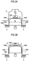
- FIG. 2A and FIG. 2B are drawings schematically illustrating an exemplary press forming apparatus.
- the press forming apparatus has a punch 1 attached to a lower holder (stationary holder), and a die 2 attached to an upper holder (moving holder), and is configured to bring up or down the die 2 attached with a gas cylinder 3 ("down" in FIG. 2A and FIG. 2B ) so as to push the punch 1 into the die 2, to thereby stamp the sheet metal 100 between the die 2 and the punch 1.
- the press forming apparatus has a pair of blank holders 5 each of which being attached with an independent gas cylinder 4, and is configured to bring up or down the blank holders 5 ("up” in FIG. 2A and FIG. 2B ) so as to implement draw bending, according to which the punch 1 is pushed into the die 2 for press forming, while clamping the edge portions of the sheet metal 100 (flanges 100a of the stamped product 100A illustrated in FIG. 1 ) between the blank holders 5 and the die 2 under fold pressure (tension).
- the present invention is not limited to the draw bending, and is also applicable to form bending according to which the metal sheet is stamped without being applied with the fold pressure (tension). While the press forming apparatus shown above is configured to move the die 2 towards the punch 1, it may alternatively be configured to move the punch 1 towards the die 2. Another possible configuration is such that the die 2 is attached to the lower holder, and the punch 1 is attached to the upper holder.
- the sheet metal 100 is set on the press forming apparatus, and the die 2 is brought down, achieving a state that the edge portions of the sheet metal 100, or the flanges 100a, are held between the blank holders 5 and the die 2.
- the fold pressure of the blank holders 5 applied to the sheet metal 100 herein is controlled by adjusting pressure of the gas cylinders 4.
- the die 2 is further brought down from this state, thereby the punch 1 is kept pressed in the die 2.
- the edge portions (flanges 100a) of the sheet metal 100 are applied with the fold pressure (tension) by the blank holders 5, so that portions not constrained by the blank holders 5 and the punch 1 (vertical walls 100b of the stamped product 100A illustrated in FIG. 1 ) are thinned due to plastic deformation, and work-hardened.
- the die 2 further descends from this state down to the bottom dead center of the press forming process, and thereby the sheet metal 100 is stamped between the punch 1 and the die 2.
- the stamped product (vehicle component) 100A having the hat-like cross sectional shape illustrated in FIG. 1 may be obtained.
- the sheet metal 100 will be work-hardened in the vertical walls 100b, and this means while the vertical walls 100b might be enhanced in the deformation strength, the vertical walls 100b will be thinned at the same time.
- the obtained stamped product (vehicle component) 100A was, therefore, improved in the rate of absorption of externally applied impact energy but not so much as expected, proving it difficult to improve the crash safety performance.
- Another known method is such as press forming the sheet metal 100 by form bending, without using the blank holders 5, and therefore applying no fold pressure (tension).
- the sheet metal 100 in this case, however, causes the work hardening neither in the ridge where the metal sheet 100 was bent, nor in the region other than the ridge, again proving it difficult to enhance the rate of absorption of externally applied impact energy.
- the present inventors then conducted thorough investigations to address the problems above, and found out a press forming method based on a plurality of times of press forming, which is capable of introducing a large work hardening into a bent ridge of a vehicle component such as vehicle frame, without decreasing the sheet thickness, and also found that a vehicle component, which makes a wise use of such work hardening, could be improved largely in the rate of absorption of impact energy externally applied in case of collision or the like.
- the findings led us to propose the present invention.
- a press forming method press forming a workpiece between a die and a punch, while pushing the punch into the die by means of a relative motion of the die and the punch.
- the method characteristically includes producing an intermediate molding having a ridge formed in a predetermined part of the workpiece (in this embodiment, portions corresponded to angular parts between the vertical walls 100b and the ceiling 100c as described later), and then press forming the intermediate molding into a final shape, to thereby substantially thicken and work-harden the predetermined part of the workpiece.
- the sheet metal is subjected to draw bending or bending to produce the intermediate product having a section line length larger than that of the final product, and the ridge is re-shaped into the product geometry, immediately in front of the bottom dead center of the succeeding press forming process.
- the ridge undergoes compressive plastic deformation, and thereby a large work hardening may be introduced without reducing the thickness.
- the intermediate molding is produced from the metal sheet so as to have a large cross sectional profile with a ratio of line length 2% or more larger and 10% or smaller, than that of the final product geometry, and is further stamped into a cross sectional profile of the final product geometry.
- the reason why the cross sectional profile was determined as described above is that yield point elongation is observed for some materials, so that if the ratio is smaller than 2%, the work hardening may be insufficient and an expected level of deformation strength is not always attainable.
- the reason why the ratio of section line length was determined as 10% or smaller is that, if the ratio exceeds the value, folds ascribable to an extra material may occur in the second step, enough to prevent production of good moldings.
- a thin sheet undergoes compressive deformation only with difficulty due to buckling as described above.
- the present inventors now made it possible to give compressive deformation by combining an optimal ratio of lengths in the first step and the second step, with the ratio of widths of a pad and the punch.
- FIG. 3A and FIG. 3B are drawings schematically illustrating an exemplary press forming apparatus used in the second step.
- the press forming apparatus is roughly configured by a punch 1' attached to a lower holder, a die 2' supported by an upper holder, and a pad 6 supported by the upper holder.
- an intermediate molding 100B is held between the punch 1' and the pad 6 as illustrated in FIG. 3A .
- the die 2' descends to the bottom dead center as illustrated in FIG. 3B , to thereby give the product geometry. Since the intermediate molding 100B in this case is constrained by the pad 6 and the material thereof is kept immobilized, so that the ridges are compressively deformed in an efficient manner.
- magnitude and region of the compressive deformation of the ridges will vary, depending on ratio of width W 1 of the pad 6 relative to width W 2 of the punch 1'. More specifically, if the ratio of widths W 1 /W 2 of the pad 6 and the punch 1' is close to 1, only the ridges may be introduced with a large work hardening, but a risk of folds due to bucking may increase. Therefore, the ratio of widths W 1 /W 2 of the pad 6 and the punch 1' is preferably 0.8 or smaller. In contrast, if the ratio of widths becomes small, a wide region centered round the ridge may be work-hardened. From the viewpoint of effective work hardening of the ridge, the ratio of widths W 1 /W 2 is preferably adjusted to 0.4 or larger.
- the press forming method of the present invention will now be explained more specifically.
- the sheet metal 100 is stamped using the press forming apparatus illustrated in FIG. 2A and FIG. 2B .
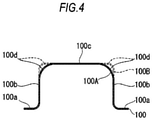
- the intermediate molding 100B is manufactured so as to have a hat-like cross sectional shape (intermediate shape) indicated by a broken line in FIG. 4 .
- the intermediate molding 100B has a section line length longer than that of the stamped product 100A having the hat-like cross sectional shape (final shape) illustrated in FIG. 1 (indicated by a solid line in FIG. 4 ).
- the intermediate molding 100B is stamped as described above, into the hat-like cross sectional shape (final shape) as illustrated by the solid line in FIG. 4 .
- the sheet metal 100 in the first step of press forming, is introduced with plastic deformation by bending as indicated by the broken line in FIG. 4 , whereas in the second step of press forming, compressive plastic deformation occurs in ridges 100d between the ceiling 100c and the vertical walls 100b of the bent sheet metal 100 as indicated by the solid line in FIG. 4 .
- the sheet metal 100 may be work-hardened to a large degree, by substantially thickening the ridges 100d in the second step of press forming.
- the sheet metal 100 is preferably shaped into the final shape (stamped product 100A), by repetitively, at least once or more, press forming the intermediate molding 100B which is produced from the sheet metal 100 so as to have an intermediate shape with a section line length 2% or more larger than the section line length of the final shape. This is because yield point elongation is observed for some materials, so that if the ratio is smaller than 2%, the work hardening may be insufficient and an expected level of deformation strength is not always attainable.
- the sheet metal 100 is also preferably shaped into the final shape (stamped product 100A), by repetitively, at least once or more, press forming the intermediate molding 100B which is produced so as to have an intermediate shape with a section line length 1 mm or more longer than the section line length of the final shape, or the intermediate molding 100B which is produced so as to have an intermediate shape with a radius of the ridge section 1 mm or more smaller than the radius of the ridge section of the final shape.
- the present invention it is now possible to enhance deformation strength of the ridges 100d which are substantially thickened and work-hardened, without subjecting the sheet metal 100 to any types of annealing such as hot press forming or induction hardening.
- the stamped product 100A (vehicle component) having the hat-like cross sectional shape (final shape) illustrated in FIG. 1 , may be obtained.
- the thus-obtained stamped product 100A may successfully be used as a vehicle component capable of absorbing externally applied impact energy by buckling deformation. More specifically, the vehicle component is composed of the stamped product 100A having the hat-like cross sectional shape, in which the bent ridges 100d are thickened and work-hardened, and thereby the ridges 100d have a deformation strength much larger than that of the other parts. Accordingly, it is now possible to largely increase the rate of absorption of externally applied impact energy in case of collision or the like.
- automotive structural components such as front frame, side sill outer and so forth, may be work-hardened in a predetermined part thereof, basically by means of the conventional cold press forming, without introducing any new facilities for hot press forming or hardening such as induction hardening, and may thereby be enhanced in the collision strength.
- the components may be thinned without degrading the crash safety performance. It is also possible to provide automotive structural components (vehicle components) which satisfy both of reduction in vehicle weight and improvement in the crash safety performance, while suppressing the manufacturing cost from excessively increasing.
- Example The effects of the present invention will further be clarified below referring to Example. Note that the present invention is not limited to Example below, and may be implemented in an appropriately modified manner without departing from the spirit thereof.
- a 590-MPa-class dual phase steel sheet of 1.2 mm thick was prepared as the sheet metal 100, the steel sheet was stamped in the first step into the intermediate shape (intermediate molding), and the intermediate molding was stamped in the second step into the final shape, to thereby manufacture the stamped product having the hat-like cross sectional shape illustrated in FIG. 1 .
- the press forming was conducted while setting the radius R of the stamped shoulder of the intermediate shape (intermediate molding) 1 mm smaller than that of the final shape (stamped product).
- the thus-manufactured stamped product having the hat-like cross sectional shape was butted with a parallel flat closing plate, and spot-welded on the flanges at 30 mm pitch, to thereby obtain a sample piece S having the individual dimensions as illustrated in FIG. 6 .
- the sample piece S of the present invention was subjected to a falling weight test in which a 260 kg weight was allowed to freely fall from a height of 3 m, and allowed to collide at an initial velocity of 7.7 m/s. Reaction force to material deformation was measured using a load cell attached to the fixed end side, and displacement was measured using a laser displacement meter.
- the energy absorption by the component was found to increase by approximately 10%, by introducing a large work hardening into the steel sheet without reducing the thickness.
- the stamped product 100A therefore has, as a result of draw bending (press forming) of the sheet metal (workpiece) 100, the final shape characterized by the hat-like cross sectional shape having the pairs of flanges 100a and the vertical walls 100b, and the ceiling 100c.
- the obtainable stamped product (vehicle component) 100A is improved in the rate of absorption of externally applied impact energy, but not so much as expected, proving it difficult to improve the crash safety performance, as described previously in the first embodiment.
- Another known method is such as press forming the sheet metal 100 by form bending, without using the blank holders 5, and therefore applying no fold pressure (tension).
- the sheet metal 100 in this case is, however, work-hardened neither in the ridge where the metal sheet 100 was bent, nor in the region other than the ridge, again proving it difficult to enhance the rate of absorption of externally applied impact energy.
- a press forming method press forming a workpiece between a die and a punch, while pushing the punch into the die by means of a relative motion of the die and the punch.
- the method characteristically includes producing an intermediate molding having the ridges formed in a predetermined part of the workpiece (in this embodiment, a portion corresponded to the ceiling 100c as described later), and then press forming the intermediate molding into a final shape, to thereby substantially thicken and work-harden the predetermined part of the workpiece.
- the press forming method of the second embodiment includes a step of forming the ridges in a predetermined part of the workpiece, and a step of flattening and thickening, and thereby work-hardening the part having the ridges provided therein.
- the press forming method according to the second embodiment of the present invention will be explained more specifically.
- the sheet metal 100 is stamped using a press forming apparatus illustrated in FIG. 8 , while embossing predetermined parts of the sheet metal 100.
- the press forming apparatus used for embossing in the first step is roughly configured by a punch 11 having projections 11a and attached to a lower holder, and a die 12 having recesses 12a and attached to an upper holder.
- a punch 11 having projections 11a and attached to a lower holder
- a die 12 having recesses 12a and attached to an upper holder.
- the intermediate molding 100B having an intermediate shape characterized by a plurality of embossments (irregularities) B formed in the center portion of the sheet metal 100 (the ceiling 100c of the stamped product 100A illustrated in FIG. 1 ), is produced.
- the embossments B as the ridges are located to the ceiling 100c.
- the embossments B have a convex curve as illustrated in FIG. 8 , just looking like ridges.
- FIG. 8 illustrates an exemplary case where two embossments B are formed on the intermediate molding 100B
- the number of embossments B formed on the intermediate molding 100B is not specifically limited, and the geometry and number thereof may appropriately be modified.
- the thus-embossed sheet metal 100 (intermediate molding 100B) is stamped in the second step, using the press forming apparatus illustrated in FIG. 2 .
- the stamped product (vehicle component) 100A having the hat-like cross sectional shape illustrated in FIG. 1 may be obtained.
- the die 2 further descends from this state so as to push the punch 1 into the die 2.
- the flanges 100a are held under the fold pressure (tension) by the blank holders 5, so that the vertical walls 100b of the sheet metal 100 which are not constrained by the blank holders 5 and the punch 1 are thinned by plastic deformation, and work-hardened.
- the die 2 further descends from this state down to the bottom dead center, and thereby the sheet metal 100 is stamped between the punch 1 and the die 2.
- the embossments B are squashed between the punch 1 and the die 2, and thereby the ceiling 100c of the sheet metal 100 is flattened.
- the ceiling 100c of the sheet metal 100 which is the portion corresponded to the ridge in this example, may be work-hardened. More specifically, the sheet metal 100 is introduced with plastic deformation by bulging in the process of embossing, on the other hand, introduced with compressive plastic deformation in the process of press forming as a result of squashing of the embossments B. As a consequence, the sheet metal 100 may substantially be thickened at around the embossments B by the press forming in the second step, and is thereby introduced with a large work hardening.
- the work-hardened part described above may be enhanced in the deformation strength, without subjecting the sheet metal 100 to any types of annealing such as hot press forming or induction hardening.
- the thus-obtained stamped product 100A may successfully be used as a vehicle component capable of absorbing externally applied impact energy by buckling deformation. More specifically, the vehicle component is composed of the stamped product 100A having the hat-like cross sectional shape, in which a predetermined part in the longitudinal or width-wise direction thereof is work-hardened, and thereby the part has a deformation strength much larger than that of the other parts. Accordingly, it is now possible to largely increase the rate of absorption of externally applied impact energy in case of collision or the like.
- automotive structural components such as front frame, side sill outer and so forth, may be work-hardened in a predetermined part thereof, basically by means of the conventional cold press forming, without introducing any new facilities for hot press forming or hardening such as induction hardening, and may thereby be enhanced in the collision strength.
- the components may be thinned without degrading the crash safety performance. It is also possible to provide automotive structural components (vehicle components) which satisfy both of reduction in vehicle weight and improvement in the crash safety performance, while suppressing the manufacturing cost from excessively increasing.
- the second embodiment described above dealt with the case where the sheet metal (workpiece) 100 was embossed to produce the intermediate molding 100B, and the intermediate molding 100B was then stamped so as to flatten the embossed part. It is alternatively possible in the present invention to produce the intermediate molding by embossing the sheet metal 100, after completion of, or at the same time with the press forming of the sheet metal 100, and then to stamp the intermediate molding to thereby flatten the embossed part. Also in this case, the effects same as those in the above-described embodiments may be obtained.
- the sheet metal 100 is stamped to produce an intermediate molding 100C having an intermediate shape characterized by the embossments provided to the sheet metal 100.
- the press forming apparatus is roughly configured by a punch 11' having projections 11'a and attached to a lower holder, and a die 12' having recesses 12'a and attached to an upper holder.
- the sheet metal 100 is stamped as the punch 11' is pushed into the die 12', and the sheet metal 100 is concomitantly embossed on the ceiling 100c thereof as the projections 11'a are pushed into the recesses 12'a.
- the intermediate molding 100C having a plurality of embossments (irregularities) B formed on the ceiling 100c of the sheet metal 100, is produced.
- the thus-embossed sheet metal 100 (intermediate molding 100C) is stamped.
- the stamped product (vehicle component) 100A having the hat-like cross sectional shape illustrated in FIG. 1 may be obtained.
- the part embossed between the die 2 and the punch 1 is flattened similarly to the case of press forming of the intermediate molding 100B, and thereby the part may be work-hardened.
- the sheet metal 100 may be enhanced in the deformation strength specifically in the part substantially thickened and work-hardened as described above, without subjecting the sheet metal 100 to any types of annealing such as hot press forming or induction hardening.
- the sheet metal 100 is preferably shaped into the final shape (stamped product 100A), by repetitively, at least once or more, press forming the intermediate molding 100B or 100C which is produced from the sheet metal 100 so as to have an intermediate shape with a section line length 2% or more larger than the section line length of the final shape. This is because yield point elongation is observed for some materials, so that if the ratio is smaller than 2%, the work hardening may be insufficient and an expected level of deformation strength is not always attainable.
- Example The effects of the present invention will be more clarified below referring to Example. Note that the present invention is not limited to Example below, and may be implemented in an appropriately modified manner without departing from the spirit thereof.
- a 590-MPa-class dual phase steel sheet of 1.2 mm thick was prepared as the sheet metal 100, and the steel sheet was stamped by a press forming method of the present invention illustrated in FIG. 8 , FIG. 9A and FIG. 9B , thereby the stamped product having the hat-like cross sectional shape illustrated in FIG. 1 was manufactured.
- embossments of 10 mm in diameter and 3 mm in height were provided so as to align two in the width-wise direction and 30 in the longitudinal direction.
- the second step illustrated in FIG. 9A and FIG. 9B all of the embossments were squashed and flattened.
- the thus-manufactured stamped product having the hat-like cross sectional shape was butted with a parallel flat closing plate, and spot-welded on the flanges at 30 mm pitch, to thereby obtain a sample piece S having the individual dimensions illustrated in FIG. 6 , as explained previously in the first embodiment.
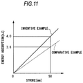
- the sample piece S of the present invention was subjected to a falling weight test in which a 260 kg weight was allowed to freely fall from a height of 3 m, and allowed to collide at an initial velocity of 7.7 m/s. Reaction force to material deformation was measured using a load cell attached to the fixed end side, and displacement was measured using a laser displacement meter.
- the energy absorption by the component was found to increase by approximately 10% from 3.6 kJ to 4.0 kJ, by introducing a large work hardening into the steel sheet without decreasing the thickness.
- the ridges formed in the intermediate molding 100B were exemplified by those formed at the angular parts between each of the vertical walls 100b and the ceiling 100c.
- the ridges are typically formed so as to continuously extend in the longitudinal direction of the intermediate molding 100B (in FIG. 6 , the direction z of beam of the stamped product).
- a plurality of, or a plurality of lines of ridges may be formed in this case.
- the plurality of lines of ridges may suffice if they extend as a whole in the longitudinal direction of the intermediate molding 100B, even if each of them is formed in a fragmental, or discontinuous manner. For example, they may be aligned in a staggered manner as a whole.
- the press forming method capable of enhancing deformation strength of a workpiece without annealing, and by using the workpiece after being molded by the press forming method, it is now possible to provide a vehicle component successfully enhanced in the rate of absorption of externally applied impact energy, and excellent in the crash safety performance.
Applications Claiming Priority (4)
| Application Number | Priority Date | Filing Date | Title |
|---|---|---|---|
| JP2011113629 | 2011-05-20 | ||
| JP2011113630 | 2011-05-20 | ||
| EP12789906.0A EP2711104B1 (fr) | 2011-05-20 | 2012-05-16 | Procédé de formage par presse |
| PCT/JP2012/062522 WO2012161050A1 (fr) | 2011-05-20 | 2012-05-16 | Procédé de moulage sous pression et composant de véhicule |
Related Parent Applications (2)
| Application Number | Title | Priority Date | Filing Date |
|---|---|---|---|
| EP12789906.0A Division-Into EP2711104B1 (fr) | 2011-05-20 | 2012-05-16 | Procédé de formage par presse |
| EP12789906.0A Division EP2711104B1 (fr) | 2011-05-20 | 2012-05-16 | Procédé de formage par presse |
Publications (1)
| Publication Number | Publication Date |
|---|---|
| EP3943204A1 true EP3943204A1 (fr) | 2022-01-26 |
Family
ID=47217130
Family Applications (2)
| Application Number | Title | Priority Date | Filing Date |
|---|---|---|---|
| EP21191036.9A Pending EP3943204A1 (fr) | 2011-05-20 | 2012-05-16 | Procédé de formage à la presse |
| EP12789906.0A Active EP2711104B1 (fr) | 2011-05-20 | 2012-05-16 | Procédé de formage par presse |
Family Applications After (1)
| Application Number | Title | Priority Date | Filing Date |
|---|---|---|---|
| EP12789906.0A Active EP2711104B1 (fr) | 2011-05-20 | 2012-05-16 | Procédé de formage par presse |
Country Status (9)
| Country | Link |
|---|---|
| US (2) | US9511403B2 (fr) |
| EP (2) | EP3943204A1 (fr) |
| JP (1) | JP5610073B2 (fr) |
| CN (1) | CN103547388B (fr) |
| BR (1) | BR112013029768A2 (fr) |
| CA (1) | CA2836080C (fr) |
| MX (1) | MX345043B (fr) |
| TW (1) | TWI510306B (fr) |
| WO (1) | WO2012161050A1 (fr) |
Families Citing this family (39)
| Publication number | Priority date | Publication date | Assignee | Title |
|---|---|---|---|---|
| EP2796221B1 (fr) * | 2011-12-22 | 2022-12-21 | Nippon Steel Corporation | Produit embouti |
| MX361908B (es) * | 2013-01-07 | 2018-12-19 | Nippon Steel & Sumitomo Metal Corp | Componente de prensa y metodo y dispositivo para la manufactura del mismo. |
| CN104918725B (zh) | 2013-01-16 | 2016-09-14 | 新日铁住金株式会社 | 冲压成型方法 |
| DE102013103751A1 (de) * | 2013-04-15 | 2014-10-16 | Thyssenkrupp Steel Europe Ag | Verfahren zur Herstellung von hochmaßhaltigen Halbschalen und Vorrichtung zur Herstellung einer Halbschale |
| EP3020492B1 (fr) * | 2013-07-09 | 2020-05-06 | JFE Steel Corporation | Procédé de définition de forme moulée préliminaire et procédé de moulage de plaque |
| WO2015046023A1 (fr) | 2013-09-24 | 2015-04-02 | 新日鐵住金株式会社 | Dispositif pour fabriquer un élément ayant une section transversale en oméga |
| JP5708757B1 (ja) * | 2013-10-30 | 2015-04-30 | Jfeスチール株式会社 | プレス成形方法 |
| US10406582B2 (en) * | 2013-12-06 | 2019-09-10 | Nippon Steel Corporation | Press-forming apparatus, method for producing press-formed product using the forming apparatus, and press-formed product |
| CN105960295B (zh) * | 2014-01-28 | 2018-04-24 | 杰富意钢铁株式会社 | 冲压成型方法、冲压成型部件的制造方法以及在这些方法中使用的预成型形状的确定方法 |
| US10828685B2 (en) * | 2014-05-14 | 2020-11-10 | Nippon Steel Corporation | Blank, and pressed article manufacturing method |
| CN104070123B (zh) * | 2014-05-27 | 2016-11-16 | 安徽红桥金属制造有限公司 | 一种便于脱模的冲压装置 |
| CN107148320A (zh) * | 2014-11-12 | 2017-09-08 | 新日铁住金株式会社 | 压制成型品的制造方法及制造装置 |
| BR112017013317A2 (pt) * | 2014-12-22 | 2018-01-02 | Nippon Steel & Sumitomo Metal Corporation | método de fabricação de componente com corte transversal em formato de chapéu |
| US10807137B2 (en) | 2015-01-26 | 2020-10-20 | Nippon Steel Corporation | Production method for producing a press-formed product |
| US10213819B2 (en) * | 2015-02-27 | 2019-02-26 | Sango Co., Ltd. | Press forming method |
| CA2977203A1 (fr) * | 2015-03-03 | 2016-09-09 | Nippon Steel & Sumitomo Metal Corporation | Procede de formage a la presse et dispositif de formage a la presse |
| JP6242363B2 (ja) * | 2015-03-31 | 2017-12-06 | 日新製鋼株式会社 | 成形材製造方法 |
| KR101928686B1 (ko) * | 2015-04-22 | 2018-12-12 | 신닛테츠스미킨 카부시키카이샤 | 프레스 성형품의 제조 방법, 프레스 성형품 및 프레스 장치 |
| CA2984746C (fr) | 2015-05-22 | 2020-03-10 | Nippon Steel & Sumitomo Metal Corporation | Article moule a la presse et procede pour la conception de ce dernier |
| CN108367328B (zh) * | 2015-12-08 | 2019-08-20 | 日本制铁株式会社 | 冲压成型品的制造方法、冲压装置以及冲压生产线 |
| US10493512B2 (en) * | 2016-01-21 | 2019-12-03 | Nippon Steel Corporation | Press-molded article manufacturing method and press apparatus |
| JP6659380B2 (ja) * | 2016-01-29 | 2020-03-04 | 株式会社神戸製鋼所 | プレス成形品の製造方法及びプレス成形装置 |
| GB2547016B (en) * | 2016-02-04 | 2019-04-24 | Crown Packaging Technology Inc | Metal containers and methods of manufacture |
| WO2017175730A1 (fr) * | 2016-04-04 | 2017-10-12 | 新日鐵住金株式会社 | Procédé de production d'article moulé à la presse et sa chaîne de production |
| CN106238572B (zh) * | 2016-08-31 | 2018-12-04 | 江苏艾锐博精密金属科技有限公司 | 一种摄像头支架连续模冷冲拉伸工艺 |
| DE102016118418A1 (de) | 2016-09-29 | 2018-03-29 | Thyssenkrupp Ag | Verfahren zur Herstellung eines geformten Bauteils mit einem maßhaltigen Zargenbereich |
| US10391537B2 (en) * | 2017-03-30 | 2019-08-27 | Ford Motor Company | Method and system for flanging a metal piece |
| CN110709181B (zh) * | 2017-06-07 | 2021-07-20 | 日本制铁株式会社 | 冲压成型品的制造方法以及冲压生产线 |
| JP6777102B2 (ja) * | 2017-12-13 | 2020-10-28 | Jfeスチール株式会社 | プレス成形方法 |
| US20190296374A1 (en) * | 2018-03-20 | 2019-09-26 | GM Global Technology Operations LLC | Methods for manufacturing unipolar and bipolar plates for fuel cells |
| JP6841271B2 (ja) | 2018-08-21 | 2021-03-10 | Jfeスチール株式会社 | プレス成形方法 |
| JP2020146747A (ja) * | 2019-03-15 | 2020-09-17 | 本田技研工業株式会社 | 車体フレームの製造方法、及び車体フレーム |
| JP7110144B2 (ja) * | 2019-03-15 | 2022-08-01 | 本田技研工業株式会社 | 車体フレームの製造方法 |
| JP7111057B2 (ja) * | 2019-05-15 | 2022-08-02 | Jfeスチール株式会社 | プレス成形方法 |
| CN112676416B (zh) * | 2019-10-17 | 2023-05-05 | 本田技研工业株式会社 | 车身骨架构件的制造方法 |
| JP7099435B2 (ja) * | 2019-12-02 | 2022-07-12 | Jfeスチール株式会社 | バーリング加工方法 |
| JP7099437B2 (ja) * | 2019-12-18 | 2022-07-12 | Jfeスチール株式会社 | バーリング加工方法 |
| CN111687269B (zh) * | 2020-06-09 | 2021-04-27 | 安徽江淮汽车集团股份有限公司 | 后车门外板冲压工艺方法及汽车后车门外板 |
| JP7448464B2 (ja) | 2020-12-01 | 2024-03-12 | 株式会社神戸製鋼所 | 鋼部品の製造方法 |
Citations (12)
| Publication number | Priority date | Publication date | Assignee | Title |
|---|---|---|---|---|
| JPS6182929A (ja) | 1984-09-28 | 1986-04-26 | Toupure Kk | 金属素板の曲げ方法 |
| JPH0472010A (ja) | 1990-07-09 | 1992-03-06 | Toyota Motor Corp | 高強度プレス成形品 |
| JP2006035245A (ja) * | 2004-07-23 | 2006-02-09 | Topre Corp | プレス加工品のスプリングバック制御方法 |
| JP2006213941A (ja) | 2005-02-01 | 2006-08-17 | Sumitomo Metal Ind Ltd | 焼入変形低減効果に優れた複合部品の製造方法 |
| JP2007190588A (ja) | 2006-01-19 | 2007-08-02 | Nippon Steel Corp | 金属板プレス成形方法 |
| JP2008012570A (ja) | 2006-07-06 | 2008-01-24 | Nippon Steel Corp | 形状凍結性に優れた多段プレス成形方法 |
| JP2008155749A (ja) * | 2006-12-22 | 2008-07-10 | Sumitomo Metal Ind Ltd | 衝撃吸収部材及びその製造方法 |
| JP2010064137A (ja) | 2008-09-12 | 2010-03-25 | Nippon Steel Corp | 形状凍結性に優れる多段プレス成形方法 |
| DE102008037612A1 (de) * | 2008-11-28 | 2010-06-02 | Thyssenkrupp Steel Europe Ag | Verfahren und Vorrichtung zum Herstellen hoch maßhaltiger flanschbehafteter Halbschalen |
| JP2010120062A (ja) * | 2008-11-20 | 2010-06-03 | Nissan Motor Co Ltd | プレス成形品の製造方法および製造装置、並びにプレス成形品 |
| JP2010174283A (ja) | 2009-01-28 | 2010-08-12 | Jfe Steel Corp | 延性に優れたホットプレス部材、そのホットプレス部材用鋼板、およびそのホットプレス部材の製造方法 |
| JP2011161941A (ja) * | 2010-02-04 | 2011-08-25 | Toyota Motor Corp | 骨格部材および骨格部材の製造方法 |
Family Cites Families (13)
| Publication number | Priority date | Publication date | Assignee | Title |
|---|---|---|---|---|
| JP3832927B2 (ja) * | 1997-06-02 | 2006-10-11 | プレス工業株式会社 | アクスルケースの製造方法 |
| JP4412452B2 (ja) * | 2002-11-01 | 2010-02-10 | 日産自動車株式会社 | プレス成形方法、プレス成形型及び自動車用強度部材 |
| US20040169320A1 (en) * | 2003-02-28 | 2004-09-02 | Petrucci Alan A. | Plastic injection mold assembly and method of molding threaded plastic parts |
| US20070012514A1 (en) * | 2005-07-12 | 2007-01-18 | Groy Abram D | Ladder Caddy |
| JP4697086B2 (ja) * | 2005-12-01 | 2011-06-08 | 日産自動車株式会社 | 屈曲した角部を有する成形部品およびその製造方法並びに製造装置 |
| JP4330652B2 (ja) * | 2007-03-28 | 2009-09-16 | ユニプレス株式会社 | 車両用金属製アブソーバ、車両用バンパシステム、自動車バンパ用アブソーバ及び自動車バンパシステム |
| JP5353065B2 (ja) * | 2007-05-31 | 2013-11-27 | 日産自動車株式会社 | プレス成形品、プレス成形品の製造方法および製造装置 |
| US20080299352A1 (en) * | 2007-05-31 | 2008-12-04 | Nissan Motor Co., Ltd. | Press-molded product and method of manufacturing same |
| JP4600432B2 (ja) * | 2007-05-31 | 2010-12-15 | 日産自動車株式会社 | プレス成形品およびプレス成形品の製造方法 |
| JP2008307557A (ja) * | 2007-06-13 | 2008-12-25 | Kobe Steel Ltd | 2段プレス成形法 |
| JP5244529B2 (ja) * | 2008-10-09 | 2013-07-24 | しのはらプレスサービス株式会社 | 縦型プレス機による増肉プレス加工方法 |
| CN201751037U (zh) * | 2010-07-13 | 2011-02-23 | 浙江吉利汽车有限公司 | 一种冲压拉延成型模具 |
| JP5835768B2 (ja) * | 2011-07-27 | 2015-12-24 | ダイハツ工業株式会社 | フレーム部品の製造方法 |
-
2012
- 2012-05-16 WO PCT/JP2012/062522 patent/WO2012161050A1/fr active Application Filing
- 2012-05-16 BR BR112013029768A patent/BR112013029768A2/pt not_active Application Discontinuation
- 2012-05-16 US US14/117,681 patent/US9511403B2/en active Active
- 2012-05-16 CN CN201280024208.6A patent/CN103547388B/zh active Active
- 2012-05-16 EP EP21191036.9A patent/EP3943204A1/fr active Pending
- 2012-05-16 CA CA2836080A patent/CA2836080C/fr not_active Expired - Fee Related
- 2012-05-16 MX MX2013013385A patent/MX345043B/es active IP Right Grant
- 2012-05-16 EP EP12789906.0A patent/EP2711104B1/fr active Active
- 2012-05-16 JP JP2013516311A patent/JP5610073B2/ja active Active
- 2012-05-18 TW TW101117766A patent/TWI510306B/zh not_active IP Right Cessation
-
2016
- 2016-11-01 US US15/340,823 patent/US10543521B2/en active Active
Patent Citations (12)
| Publication number | Priority date | Publication date | Assignee | Title |
|---|---|---|---|---|
| JPS6182929A (ja) | 1984-09-28 | 1986-04-26 | Toupure Kk | 金属素板の曲げ方法 |
| JPH0472010A (ja) | 1990-07-09 | 1992-03-06 | Toyota Motor Corp | 高強度プレス成形品 |
| JP2006035245A (ja) * | 2004-07-23 | 2006-02-09 | Topre Corp | プレス加工品のスプリングバック制御方法 |
| JP2006213941A (ja) | 2005-02-01 | 2006-08-17 | Sumitomo Metal Ind Ltd | 焼入変形低減効果に優れた複合部品の製造方法 |
| JP2007190588A (ja) | 2006-01-19 | 2007-08-02 | Nippon Steel Corp | 金属板プレス成形方法 |
| JP2008012570A (ja) | 2006-07-06 | 2008-01-24 | Nippon Steel Corp | 形状凍結性に優れた多段プレス成形方法 |
| JP2008155749A (ja) * | 2006-12-22 | 2008-07-10 | Sumitomo Metal Ind Ltd | 衝撃吸収部材及びその製造方法 |
| JP2010064137A (ja) | 2008-09-12 | 2010-03-25 | Nippon Steel Corp | 形状凍結性に優れる多段プレス成形方法 |
| JP2010120062A (ja) * | 2008-11-20 | 2010-06-03 | Nissan Motor Co Ltd | プレス成形品の製造方法および製造装置、並びにプレス成形品 |
| DE102008037612A1 (de) * | 2008-11-28 | 2010-06-02 | Thyssenkrupp Steel Europe Ag | Verfahren und Vorrichtung zum Herstellen hoch maßhaltiger flanschbehafteter Halbschalen |
| JP2010174283A (ja) | 2009-01-28 | 2010-08-12 | Jfe Steel Corp | 延性に優れたホットプレス部材、そのホットプレス部材用鋼板、およびそのホットプレス部材の製造方法 |
| JP2011161941A (ja) * | 2010-02-04 | 2011-08-25 | Toyota Motor Corp | 骨格部材および骨格部材の製造方法 |
Also Published As
| Publication number | Publication date |
|---|---|
| EP2711104B1 (fr) | 2023-01-11 |
| US9511403B2 (en) | 2016-12-06 |
| WO2012161050A1 (fr) | 2012-11-29 |
| JPWO2012161050A1 (ja) | 2014-07-31 |
| EP2711104A4 (fr) | 2014-11-12 |
| MX345043B (es) | 2017-01-16 |
| TWI510306B (zh) | 2015-12-01 |
| US20170056949A1 (en) | 2017-03-02 |
| US20140182349A1 (en) | 2014-07-03 |
| CA2836080C (fr) | 2016-02-02 |
| CN103547388A (zh) | 2014-01-29 |
| CA2836080A1 (fr) | 2012-11-29 |
| TW201302343A (zh) | 2013-01-16 |
| US10543521B2 (en) | 2020-01-28 |
| CN103547388B (zh) | 2015-10-07 |
| BR112013029768A2 (pt) | 2017-01-17 |
| JP5610073B2 (ja) | 2014-10-22 |
| EP2711104A1 (fr) | 2014-03-26 |
| MX2013013385A (es) | 2014-02-11 |
Similar Documents
| Publication | Publication Date | Title |
|---|---|---|
| US10543521B2 (en) | Press forming method and vehicle component | |
| JP6069223B2 (ja) | プレス成形品 | |
| KR101821074B1 (ko) | 프레스 성형체의 제조 방법 및 프레스 성형 장치 | |
| JP5380890B2 (ja) | 形状凍結性に優れたプレス成形方法およびその装置 | |
| US10239105B2 (en) | Blank steel plate, production method and production device therefor, and production method for press-formed product using blank steel plate | |
| JP5728334B2 (ja) | 衝突性能に優れた車体用のプレス成形品およびその製造方法 | |
| JP2006272413A (ja) | 湾曲状チャンネル部材の成形方法 | |
| WO2015053035A1 (fr) | Procédé pour la fabrication d'un élément structural pour une carrosserie d'automobile et dispositif de moulage par compression | |
| KR101867744B1 (ko) | 프레스 성형 방법 및 프레스 제품의 제조 방법 그리고 프레스 성형 장치 | |
| US11534815B2 (en) | Press formed product, automobile structural member with the press formed product, and method for producing press formed product | |
| JP2004168141A (ja) | 車両用荷重受け物品及びその製造方法並びにその製造装置 | |
| CN109070676B (zh) | 扭力梁制造方法、扭力梁制造装置以及扭力梁 | |
| KR102104377B1 (ko) | 토션 빔 제조 방법, 토션 빔 제조 장치 및 토션 빔 | |
| US11623260B2 (en) | Formed body, structural member, and method for producing formed body | |
| JP2006159281A (ja) | 衝撃吸収特性に優れた構造用部材のプレス成形方法 |
Legal Events
| Date | Code | Title | Description |
|---|---|---|---|
| PUAI | Public reference made under article 153(3) epc to a published international application that has entered the european phase |
Free format text: ORIGINAL CODE: 0009012 |
|
| STAA | Information on the status of an ep patent application or granted ep patent |
Free format text: STATUS: REQUEST FOR EXAMINATION WAS MADE |
|
| 17P | Request for examination filed |
Effective date: 20210912 |
|
| AC | Divisional application: reference to earlier application |
Ref document number: 2711104 Country of ref document: EP Kind code of ref document: P |
|
| AK | Designated contracting states |
Kind code of ref document: A1 Designated state(s): AL AT BE BG CH CY CZ DE DK EE ES FI FR GB GR HR HU IE IS IT LI LT LU LV MC MK MT NL NO PL PT RO RS SE SI SK SM TR |