WO2017175730A1 - Procédé de production d'article moulé à la presse et sa chaîne de production - Google Patents
Procédé de production d'article moulé à la presse et sa chaîne de production Download PDFInfo
- Publication number
- WO2017175730A1 WO2017175730A1 PCT/JP2017/013982 JP2017013982W WO2017175730A1 WO 2017175730 A1 WO2017175730 A1 WO 2017175730A1 JP 2017013982 W JP2017013982 W JP 2017013982W WO 2017175730 A1 WO2017175730 A1 WO 2017175730A1
- Authority
- WO
- WIPO (PCT)
- Prior art keywords
- punch
- press
- tip
- top plate
- formed product
- Prior art date
Links
Images


Classifications
-
- B—PERFORMING OPERATIONS; TRANSPORTING
- B21—MECHANICAL METAL-WORKING WITHOUT ESSENTIALLY REMOVING MATERIAL; PUNCHING METAL
- B21D—WORKING OR PROCESSING OF SHEET METAL OR METAL TUBES, RODS OR PROFILES WITHOUT ESSENTIALLY REMOVING MATERIAL; PUNCHING METAL
- B21D22/00—Shaping without cutting, by stamping, spinning, or deep-drawing
- B21D22/20—Deep-drawing
- B21D22/26—Deep-drawing for making peculiarly, e.g. irregularly, shaped articles
-
- B—PERFORMING OPERATIONS; TRANSPORTING
- B21—MECHANICAL METAL-WORKING WITHOUT ESSENTIALLY REMOVING MATERIAL; PUNCHING METAL
- B21D—WORKING OR PROCESSING OF SHEET METAL OR METAL TUBES, RODS OR PROFILES WITHOUT ESSENTIALLY REMOVING MATERIAL; PUNCHING METAL
- B21D24/00—Special deep-drawing arrangements in, or in connection with, presses
- B21D24/04—Blank holders; Mounting means therefor
- B21D24/06—Mechanically spring-loaded blank holders
-
- B—PERFORMING OPERATIONS; TRANSPORTING
- B21—MECHANICAL METAL-WORKING WITHOUT ESSENTIALLY REMOVING MATERIAL; PUNCHING METAL
- B21D—WORKING OR PROCESSING OF SHEET METAL OR METAL TUBES, RODS OR PROFILES WITHOUT ESSENTIALLY REMOVING MATERIAL; PUNCHING METAL
- B21D5/00—Bending sheet metal along straight lines, e.g. to form simple curves
- B21D5/01—Bending sheet metal along straight lines, e.g. to form simple curves between rams and anvils or abutments
-
- B—PERFORMING OPERATIONS; TRANSPORTING
- B21—MECHANICAL METAL-WORKING WITHOUT ESSENTIALLY REMOVING MATERIAL; PUNCHING METAL
- B21D—WORKING OR PROCESSING OF SHEET METAL OR METAL TUBES, RODS OR PROFILES WITHOUT ESSENTIALLY REMOVING MATERIAL; PUNCHING METAL
- B21D53/00—Making other particular articles
- B21D53/88—Making other particular articles other parts for vehicles, e.g. cowlings, mudguards
Definitions
- the present invention relates to a method for producing a press-formed product and a production line. More specifically, the present invention relates to a manufacturing method and a manufacturing line of a press-formed product used for an automobile.
- Automotive frame parts for example, pillars
- Automobile frame parts and the like have a groove-shaped or hat-shaped cross-sectional shape for securing strength.
- automobile frame parts and the like may have a stepped portion on the top plate. This is for mounting other parts.
- a blank is press-molded into a part having a stepped part on the top plate part, wrinkles may occur in the molded part.
- a part having a stepped portion on the top plate may be formed by drawing.
- the step portion means an inclined region connecting regions having different heights, and the inclination angle is not limited to 90 °.
- Patent Document 1 A manufacturing method for suppressing wrinkles of a press-formed product is disclosed in Japanese Patent Application Laid-Open No. 2014-240078 (Patent Document 1).
- Patent Document 2 The manufacturing method which suppresses the wrinkles and cracking of a press-formed product is disclosed in International Publication No. 2011/145679 (Patent Document 2).
- Patent Document 1 discloses a method of manufacturing a press-formed product bent into an L shape while suppressing generation of wrinkles by drawing.
- press molding is performed while a region bent into an L shape is constrained by a pad.
- Patent Document 1 describes that the generation of wrinkles can be suppressed in an L-shaped bent region.
- Patent Document 2 discloses a method of manufacturing a press-formed product bent into an L shape or a T shape by bending.
- a bent region of the press-formed product is formed in a state where a part of the top plate portion of the press-formed product is constrained by a pad.
- Patent Document 2 describes that the generation of wrinkles can be suppressed in a region bent into an L shape or a T shape.
- Patent Documents 1 and 2 are intended for manufacturing a press-formed product bent into an L-shape or the like. Therefore, Patent Documents 1 and 2 do not disclose the production of a press-formed product having a step portion on the top plate portion.
- An object of the present invention is to provide a production method and a production line thereof capable of suppressing the occurrence of wrinkles and cracks even when a press-formed product having a stepped portion on a top plate portion is produced using a high-strength metal plate. is there.
- the press-molded product manufactured by the manufacturing method according to the embodiment of the present invention includes a top plate portion and a vertical wall portion.
- the top plate has a step in the longitudinal direction.
- the step portion extends from the end portion in the width direction and crosses at least a part in the width direction.
- the vertical wall portion is adjacent to the top plate portion via a ridge line portion at an end portion in the width direction where the step portion of the top plate portion is present.
- the manufacturing method of the press-formed product of the present embodiment includes a first press process and a second press process.
- first pressing step an intermediate molded product is molded from the workpiece using the first mold.
- the intermediate molded product includes a stepped portion of the top plate portion, a temporary vertical wall portion in which at least part of the shape of the vertical wall portion adjacent to the top plate portion is formed via the ridge line portion, and a ridge line portion of the temporary vertical wall portion. And a provisional flange part adjacent to the provisional vertical wall part through a provisional ridge line part located at the end opposite to the part.
- second pressing step a press-molded product is molded from the intermediate molded product using the second mold.
- molding is performed in which the temporary ridge line portion is moved toward the temporary flange portion while at least a part of the top plate portion of the intermediate molded product is constrained.
- the production line of the present embodiment includes a first press machine and a second press machine disposed downstream of the first press machine.
- the first press includes a first punch, a first die, and a first pad.
- the first punch has a first tip portion, a first punch wall portion, and a punch flat portion.
- the first tip portion extends from the end portion in the width direction and has a step portion in the longitudinal direction so as to cross at least a part in the width direction.
- the first punch wall portion is adjacent to the first tip portion via the first punch shoulder at the end portion where the step portion of the first tip portion is located.
- the punch flat portion is adjacent to the first punch wall portion via the first punch wall portion and the punch bottom shoulder.
- the first die faces the first punch shoulder of the first punch, the first punch wall portion, and the punch flat portion.
- the first pad faces the first tip of the first punch.
- the second press includes a second punch, a second die, and a second pad.
- the second punch has a second tip portion and a second punch wall portion.
- the second tip portion has the same shape as the first tip portion.
- the second punch wall is adjacent to the second tip through a second punch shoulder at the end where the step portion of the second tip is located.
- the second die faces the second punch shoulder of the second punch and the second punch wall.
- the second pad faces the second tip of the second punch.
- the height of the second punch wall portion of the second press machine is larger than the height of the first punch wall portion of the first press machine. Note that “height” in the present invention means the size in the height direction unless a positional relationship is mentioned.
- FIG. 1 is a perspective view of a press-formed product manufactured by the manufacturing method of the present embodiment.
- FIG. 2 is a diagram showing the relationship between the size of the wrinkles and the shape of the step when the press-formed product as shown in FIG. 1 is bent in one step.
- FIG. 3 is a diagram showing the shape of a workpiece at the initial stage of press forming when press forming is performed in one process.
- FIG. 4 is a diagram showing the shape of a workpiece in the middle of press forming when press forming is performed in one process.
- FIG. 5 is a diagram illustrating a shape of a workpiece when press forming is completed in one process.
- FIG. 6 is a diagram schematically showing the stress acting on the minute elements in the vertical wall portion immediately below the step portion (inclined portion).
- FIG. 7 is a diagram showing the shape of the workpiece after completion of the first step when press molding is performed in two steps.
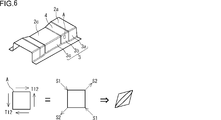
- FIG. 8 is a diagram showing the shape of a workpiece during press molding in the second step when press molding is performed in two steps.
- FIG. 9 is a diagram showing the shape of the workpiece when the second step is completed when press molding is performed in two steps.
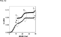
- FIG. 10 is a diagram showing the magnitude of shear strain accompanying the progress of press molding.
- FIG. 11 is a perspective view of an intermediate molded product obtained by the first pressing step.
- FIG. 12 is a diagram illustrating a state before the start of molding in the first pressing step.
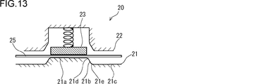
- FIG. 13 is a diagram showing an initial state of molding in the first pressing step.
- FIG. 14 is a diagram illustrating a state at the completion of molding in the first pressing step.
- FIG. 15 is a cross-sectional view showing a first mold when drawing is performed in the first pressing step.
- FIG. 16 is a diagram illustrating a state before the start of molding in the second pressing step.
- FIG. 17 is a diagram showing a state in the initial stage of the second pressing step.
- FIG. 18 is a diagram showing a state at the completion of molding in the second pressing step.
- FIG. 19 is a perspective view showing an intermediate molded product of the example of the present invention.
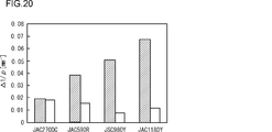
- FIG. 20 is a diagram showing the results of the present invention example and the comparative example.
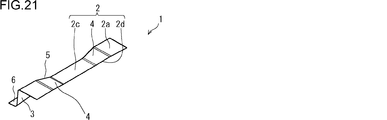
- FIG. 21 is a perspective view showing an example of a press-formed product of the present embodiment.
- FIG. 22 is a perspective view showing an example of a press-formed product of the present embodiment.
- FIG. 23 is a diagram showing a production line of the present embodiment.
- the press-formed product manufactured by the manufacturing method of the present embodiment includes a top plate portion and a vertical wall portion.
- the top plate has a step in the longitudinal direction.
- the step portion extends from the end portion in the width direction and crosses at least a part in the width direction.
- the vertical wall portion is adjacent to the top plate portion via a ridge line portion at an end portion in the width direction where the step portion of the top plate portion is present.
- the manufacturing method of the press-formed product of the present embodiment includes a first press process and a second press process.
- first pressing step an intermediate molded product is molded from the workpiece using the first mold.
- the intermediate molded product includes a stepped portion of the top plate portion, a temporary vertical wall portion in which at least part of the shape of the vertical wall portion adjacent to the top plate portion is formed via the ridge line portion, and a ridge line portion of the temporary vertical wall portion. And a provisional flange part adjacent to the provisional vertical wall part through a provisional ridge line part located at the end opposite to the part.
- second pressing step a press-molded product is molded from the intermediate molded product using the second mold.
- molding is performed in which the temporary ridge line portion is moved toward the temporary flange portion while at least a part of the top plate portion of the intermediate molded product is constrained.
- the workpiece is press-molded in two different processes.
- an intermediate molded product molded to a part of the height of the press-molded product (finished product) is obtained.
- the intermediate molded product includes a provisional flange portion.
- a region corresponding to the provisional flange portion of the workpiece is constrained by a mold.
- the flow of the material accompanying the progress of press molding is suppressed in the temporary flange portion. Therefore, compared with a press-molded product molded by only one pressing process, the intermediate molded product suppresses shear strain that causes wrinkles.
- the shear strain generated in the press-formed product is suppressed as compared with the case of forming in only one press step. The This is because the shear strain generated in the intermediate molded product is small. Therefore, wrinkles are unlikely to occur in the press-formed product.
- the height of the temporary vertical wall portion adjacent to the top plate portion of the lower step portion (lower step portion) of the intermediate molded product is preferably 50% or less of the height of the vertical wall portion of the press molded product.
- the shear strain increases with the progress of press molding. Therefore, if the molding height in the first step is lower than the molding height in the second step, the shear strain of the intermediate molded product obtained in the first step can be effectively reduced. More preferably, in the first pressing step, the entire area of the ridge line portion of the press-formed product is formed.
- the manufacturing method of this embodiment is particularly effective when a high-strength workpiece is formed.
- the tensile strength of the workpiece is preferably 590 MPa or more.
- the tensile strength of the workpiece is more preferably 980 MPa or more.
- the production line of the present embodiment includes a first press machine and a second press machine disposed downstream of the first press machine.
- the first press machine has the following configuration (1) or (2).
- the first press includes a first punch, a first die, and a first pad.
- the first punch has a first tip portion, a first punch wall portion, and a punch flat portion.
- the first tip portion extends from the end portion in the width direction and has a step portion in the longitudinal direction so as to cross at least a part in the width direction.
- the first punch wall portion is adjacent to the first tip portion via the first punch shoulder at the end portion where the step portion of the first tip portion is located.
- the punch flat portion is adjacent to the first punch wall portion via the first punch wall portion and the punch bottom shoulder.
- the first die faces the first punch shoulder of the first punch, the first punch wall portion, and the punch flat portion.
- the first pad faces the first tip of the first punch.
- the first pad has a shape obtained by inverting the uneven shape of the first tip.
- “facing” means that the shape of the mold is reversed in addition to the positional relationship of the mold as described above. That is, if the shape of one mold is convex, the shape of the other mold facing is concave.
- the first press includes a first punch, a blank holder, and a first die.
- the first punch has a first tip portion and a first punch wall portion.
- the first tip portion extends from the end portion in the width direction and has a step portion in the longitudinal direction so as to cross at least a part in the width direction.
- the first punch wall portion is adjacent to the first tip portion via the first punch shoulder at the end portion where the step portion of the first tip portion is located.
- the blank holder is adjacent to the first punch.
- the first die faces the first punch and the blank holder.
- the second press includes a second punch, a second die, and a second pad.
- the second punch has a second tip portion and a second punch wall portion.
- the second tip portion has the same shape as the first tip portion.
- the second punch wall is adjacent to the second tip through a second punch shoulder at the end where the step portion of the second tip is located.
- the second die faces the second punch shoulder of the second punch and the second punch wall.
- the second pad faces the second tip of the second punch.
- the height of the second punch wall portion of the second press machine is larger than the height of the first punch wall portion of the first press machine.
- FIG. 1 is a perspective view of a press-formed product manufactured by the manufacturing method of the present embodiment.
- the press-formed product 1 includes a top plate portion 2 and a vertical wall portion 3.
- the top plate portion 2 has a step portion 4, a top plate portion 2a above the step, and a top plate portion 2c below the step in the longitudinal direction.
- the top plate part 2 a at the upper part of the step is connected to the step part 4.
- the step portion 4 is connected to the top plate portion 2c below the step.
- the step portion 4 extends from the end portion 2 d in the width direction of the top plate portion 2.
- the step 1 shows a case where the stepped portion 4 exists over the entire width direction of the press-formed product 1. However, the step portion 4 may not be present in the entire width direction of the press-formed product 1.
- the step part 4 may cross at least a part in the width direction of the press-formed product 1 (for example, FIG. 22).
- the contour of the ridge line portion 5 is R-shaped.
- the vertical wall 3 is adjacent to the top 2 via the ridge 5.
- the vertical wall portion 3 includes a vertical wall portion 3a immediately below the stepped portion, a vertical wall portion 3b immediately below the stepped portion, and a vertical wall portion 3c immediately below the stepped portion.
- the vertical wall portion 3a immediately below the upper portion of the step is adjacent to the top plate portion 2a of the upper portion of the step through the ridge line portion 5.
- the vertical wall portion 3 b immediately below the step portion is adjacent to the step portion 4 of the top plate portion 2 through the ridge line portion 5.
- the vertical wall portion 3 c immediately below the step bottom is adjacent to the top plate portion 2 c below the step via the ridge line portion 5.
- FIG. 1 shows a case where the cross-sectional shape perpendicular to the longitudinal direction of the press-formed product 1 is a hat shape. Therefore, the press-formed product 1 includes the flange portion 6.
- the cross-sectional shape of the press-formed product 1 may not be a hat shape. Specifically, it may be a one-hat shape having only one flange portion 6 or a groove shape in which the flange portion 6 becomes a vertical wall portion during molding.
- the press-formed product 1 does not have to be a hat shape or the like, and may be a half shape of the above shape (see FIG. 21).
- the step part 4 does not need to cross the top-plate part 2 (refer FIG. 22).
- the stepped portion 4 of the press-formed product 1 may be one, three, or four, and the number of stepped portions may be an arbitrary number.
- the occurrence of wrinkles in the press-formed product is related to the height H of the stepped portion of the top plate portion and the curvature radius R of the cross section of the ridge line portion of the press-formed product. If the height H of the step portion of the top plate portion is large, large wrinkles are generated. If the curvature radius R of the cross section of the ridge line portion is small, large wrinkles are generated.
- the inventors investigated the relationship between the height H of the stepped portion of the top plate portion of the press-formed product and the radius of curvature R of the ridge line portion of the press-formed product and the size of the wrinkles by simulation.
- FIG. 2 is a diagram showing the size of wrinkles when a press-molded product as shown in FIG. 1 is bent and formed in only one step.
- the vertical axis in FIG. 2 indicates the difference ⁇ 1 / ⁇ between the maximum value and the minimum value of the main curvature.
- the horizontal axis of FIG. 2 indicates the ratio H / R between the height H of the stepped portion of the top plate portion of the press-formed product and the radius of curvature R of the ridge line portion of the press-formed product.
- the ratio H / R between the height H of the stepped portion of the top plate portion of the press-formed product as shown in FIG. 1 and the curvature radius R of the ridge line portion of the press-formed product was variously changed.
- regulated by the Japan Iron and Steel Federation standard were used as a workpiece.
- the square mark in FIG. 2 shows the result of JAC270DC, and the diamond mark shows the result of JSC980Y.
- draw forming is suitable for suppressing wrinkles generated in the vertical wall 3b immediately below the step portion and the vertical wall 3c immediately below the step portion of the press-formed product.
- a high-strength metal plate is formed by drawing, cracks are likely to occur. Therefore, the shape of the press-formed product targeted by the present invention cannot be formed by only one drawing. Therefore, the present inventors provide a manufacturing method capable of suppressing wrinkles generated in the vertical wall portion 3b immediately below the step portion and the vertical wall portion 3c immediately below the step portion even if the high-strength metal plate is press-formed by bending. investigated.
- the present inventors investigated the size of wrinkles when a press-formed product having a stepped portion on the top plate (hereinafter also simply referred to as “press-formed product”) is formed by only one bending process. . Specifically, the shape of the workpiece during press forming was investigated by simulation using FEM (finite element method).
- 3 to 5 are diagrams showing simulation results when the press-formed product shown in FIG. 1 is formed in one process by bending.
- 3 to 4 show the shape of the workpiece during press molding.
- FIG. 3 shows the initial stage of press molding.
- FIG. 4 shows the middle stage of press molding.
- FIG. 5 shows the stage at the completion of press forming.
- 3 to 5 are sectional views of the mold at each stage for easy understanding.
- a region where a surplus occurs and a constraint by the upper and lower molds is loose is defined as a region X.
- region X is an area
- the vertical wall portion 3a immediately below the upper part of the step does not correspond to the region X because there is no surplus.
- the flange portion, which is the plate end portion, does not correspond to the region X because there is no surplus.
- the vertical wall 3b immediately below the stepped portion is likely to be wrinkled because deformation (shear deformation) that absorbs surplus occurs during molding.
- FIG. 6 is a diagram schematically showing a stress state acting on the vertical wall portion immediately below the step portion in the press-formed product of the present embodiment.
- a shear stress T12 acts in the in-plane direction of the workpiece to absorb the surplus generated in the region X in the minute element A of the vertical wall portion 3b immediately below the stepped portion.
- This shear stress T12 is decomposed into a compressive stress S1 and a tensile stress S2 in terms of principal stress.
- S1 compressive stress
- S2 a tensile stress S2 in terms of principal stress.
- the square microelement A is deformed into a parallelogram. In other words, the microelement A undergoes shear deformation. Therefore, shear strain is generated in the microelement A. This shear strain is one of the causes of worsening the wrinkles of the press-formed product.
- the degree of wrinkles due to the excess of the blank when press-molding a hat-shaped press-formed product having a stepped portion depends on the width of the top plate portion. If the width W2 (see FIG. 1) of the top plate at the bottom of the step is not more than 3 times the radius of curvature R of the ridgeline (W2 ⁇ 3R), the tensile stress in the width direction of the press-formed product acts effectively, so wrinkles Is unlikely to occur. On the other hand, when the width W2 of the top plate portion is larger than three times the radius of curvature R of the ridge portion (W2> 3R), wrinkles are likely to occur.
- the radius of curvature R means the radius of curvature at the center of the plate thickness in a cross section perpendicular to the longitudinal direction at the ridge line portion at the end in the width direction of the stepped portion.
- the degree of wrinkles due to the excess of the blank when press-molding a hat-shaped press-formed product having a step portion depends on the plate thickness of the workpiece. This is because the plate thickness of the workpiece dominates the bending rigidity of the workpiece. Wrinkles are more likely to occur as the plate thickness is thinner.
- the degree of wrinkles caused by the surplus when press-molding a hat-shaped press-formed product having a stepped portion also depends on the yield strength of the workpiece. This is because the surplus at the time of press molding is caused by out-of-plane deformation under elastic deformation. The higher the yield strength of the workpiece, the easier it is for wrinkles to occur.
- the inventors of the present invention reduced the excess of the region X generated during the molding of the press-formed product 1 and the shear strain generated in the vertical wall portion 3b immediately below the stepped portion, and the vertical wall portion 3b immediately below the stepped portion of the press-formed product 1. And the method of suppressing the wrinkle which arises in the vertical wall part 3c just under a level
- the elastic out-of-plane deformation As small as possible when forming the ridge line portion at the end of the step formed by out-of-plane deformation.
- the ridge line portion is positively plastically deformed, and the out-of-plane deformation that increases with the progress of press molding may be reduced as much as possible.
- the present inventors have found that the press molding process of the press molded product 1 is divided into a plurality of parts.
- the inventors of the present invention have a step portion of the press-formed product, a ridge line portion adjacent to the step portion, and a part of the vertical wall portion adjacent to the top plate portion via the ridge line portion. It has been found that a region adjacent to the stepped portion is formed through the ridge line portion of the provisional vertical wall portion in which the shape is formed. In forming the stepped portion, it is desirable to form all regions of the stepped portion along the ridge line portion, but it is not always necessary to form all regions of the stepped portion along the ridgeline portion.
- FIGS. 7 to 9 are diagrams showing simulation results when the press-formed product shown in FIG. 1 is formed by two press formings. 7 to 9 show the shape of the workpiece during the formation of the vertical wall portion.
- the top plate portion and the ridge line portion of the press-formed product shown in FIG. 1 are formed in the first step, and the remaining portion is formed in the second step.
- FIG. 7 shows an intermediate molded product when the first step of press molding is completed and released.
- FIG. 8 shows a state during press molding in the second step.
- FIG. 9 shows a press-formed product when the press-forming of the second step is completed.
- the molding height in FIGS. 7 to 9 is the same as the molding height in FIGS.
- the surplus of the workpiece in the region Y (corresponding to the region X in FIG. 3) of the provisional flange portion 16 of the intermediate molded product 11 was smaller than that in the case shown in FIG.
- the intermediate molded product 11 molded in the first step was press-molded in the second step to obtain a press-molded product 1.
- the wrinkles read from the main curvatures of the vertical wall portion 3 b immediately below the step portion and the vertical wall portion 3 c immediately below the step portion of the press-formed product 1 are conspicuous compared to the press-formed product shown in FIG. 5. Suppressed. This point will be described with reference to FIG.
- FIG. 10 is a diagram showing the magnitude of shear strain at an arbitrary point on the vertical wall portion 3b immediately below the stepped portion as the press molding proceeds.
- the vertical axis in FIG. 10 indicates the magnitude of the shear strain
- the horizontal axis indicates the molding height of the vertical wall portion 3a immediately below the step.
- the black circles in FIG. 10 show the results when molding is performed in one pressing process.
- the white triangle mark in FIG. 10 shows the result of the first step among the results of molding in two pressing steps.
- the black triangle mark in FIG. 10 shows the result of the second step among the results of molding in two pressing steps.
- a region A in FIG. 10 shows a time when the molding height is about 10 mm, and corresponds to the state of FIGS. 3 and 7.
- a region B in FIG. 10 shows a time when the molding height is about 23 mm, and corresponds to the state of FIGS. 4 and 8.
- a region C in FIG. 10 corresponds to the state in FIGS. 5 and 9.
- the shear strain when molded by one press process is about 0.08, whereas the shear when molded by two press processes (white triangle mark).
- the strain is about 0.05.
- the shear strain is suppressed by molding the intermediate molded product including the provisional flange portion.
- the transition of the magnitude of the shear strain becomes the same in the case of molding in one press process and in the case of molding in two press processes.
- the provisional flange portion is formed, the shear strain of the vertical wall portion 3b immediately below the step portion is suppressed. As a result, the shear strain of the final product is suppressed. That is, the size of wrinkles is suppressed.
- the manufacturing method of the press-formed product of the present embodiment has been completed based on the above-described knowledge. Hereinafter, the manufacturing method of the press-formed product of this embodiment will be described.
- the manufacturing method of the press-formed product of the present embodiment includes a first press process and a second press process.
- first pressing step an intermediate molded product is formed from the workpiece using the first mold.
- second pressing step the intermediate mold formed in the first pressing step is formed into a press-molded product using the second mold.
- FIG. 11 is a perspective view of an intermediate molded product obtained by the first pressing step.
- the intermediate molded product 11 includes a top plate part 12, a ridge line part 15, a provisional vertical wall part 13, a provisional ridge line part 17, and a provisional flange part 16.
- the top plate portion 12 of the intermediate molded product 11 has the same shape as the top plate portion 2 of the press-formed product 1 (finished product) shown in FIG. Therefore, the top plate portion 12 of the intermediate molded product 11 has a step portion 14.
- the ridge line portion 15 is at the end portion 12 ⁇ / b> A in the width direction of the top plate portion 12.
- the temporary vertical wall portion 13 has at least a part of the shape of the vertical wall portion of the press-formed product.
- the provisional vertical wall portion 13 has a shape up to the middle of the vertical wall portion of the press-formed product.
- the temporary vertical wall portion 13 is adjacent to the top plate portion 12 through the ridge line portion 15.
- the angle formed by the provisional vertical wall portion 13 and the top plate portion 12 is usually a right angle or an obtuse angle for releasing the mold.
- the temporary flange portion 16 is adjacent to the temporary vertical wall portion 13 via the temporary ridge line portion 17. As shown in FIG.
- the intermediate molded product includes a top plate portion 2 c below the step of the press-formed product of FIG. 1, a ridge line portion adjacent to the top plate portion 2 c below the step, and a step bottom portion via the ridge line portion.
- the temporary vertical wall portion adjacent to the top plate portion 2c may not be provided.
- FIG. 12 shows the arrangement of the mold and the workpiece before the start of molding.
- FIG. 13 shows a state in the initial stage of molding.
- FIG. 14 shows a state when the molding is completed.
- the first mold 20 includes a first punch 21 as a lower mold and a first die 22 and a first pad 23 as an upper mold. That is, the first punch 21 faces the first die 22 and the first pad 23.
- the first punch 21 has a first tip portion 21a, a first punch wall portion 21b, and a punch flat portion 21c.
- the first tip portion 21 a extends from an end portion in the width direction of the first punch 21 and has a step portion in the longitudinal direction so as to cross at least a part of the width direction of the first punch 21. That is, the shape of the first tip portion 21a of the first punch 21 corresponds to the top plate portion of the intermediate molded product.
- the first punch wall 21b is adjacent to the first tip 21a via a first punch shoulder 21d at the end where the step portion of the first tip 21a is located. That is, the shape of the first punch wall portion 21b corresponds to the provisional vertical wall portion of the intermediate molded product.
- the first punch shoulder 21d has a shape corresponding to the ridge line portion of the intermediate molded product.
- the punch flat portion 21c is adjacent to the first punch wall portion 21b via the first punch wall portion 21b and the punch bottom shoulder 21e. That is, the shape of the punch flat portion 21c corresponds to the provisional flange portion of the intermediate molded product.
- the shape of the punch bottom shoulder 21e corresponds to the provisional ridge line portion of the intermediate molded product.
- the first die 22 opposes the first punch shoulder 21d, the first punch wall portion 21b, and the punch flat portion 21c of the first punch 21.
- a region other than the top plate portion of the intermediate molded product is formed by the first die 22 and the first punch 21.
- the first pad 23 faces the first tip 21a of the first punch 21.
- the top pad portion of the intermediate molded product is formed by the first pad 23 and the first punch 21. Further, the first pad 23 is attached to the first die 22 via the pressure member 24.
- the pressure member 24 is, for example, a spring, rubber, a hydraulic cylinder, or the like.
- the first mold 20 is installed in the first press machine 51 (see FIG. 23).
- the first pressing machine 51 performs pad bending forming of the metal plate 25.
- die was installed is demonstrated.
- a metal plate 25 is used as a workpiece (blank).
- the metal plate 25 for example, a high-strength steel plate having a tensile strength of 590 MPa or more, desirably 980 MPa or more is used. Since the yield point of a high-strength workpiece is high, wrinkles are likely to occur.
- the manufacturing method of the present embodiment is suitable for press molding of such a high-strength workpiece.
- a plated steel plate, a stainless steel plate, an alloy steel plate, an aluminum alloy plate, a copper alloy plate, or the like can be used.
- the present invention can be applied not only to a metal plate but also to a softened plastic sheet.
- the metal plate 25 is disposed at a predetermined position of the first punch 21.
- the metal plate 25 is disposed in contact with the first tip portion 21a and the first punch shoulder 21d. Further, the metal plate 25 is disposed between the punch flat portion 21 c and the first die 22. Thereafter, the first pad 23 and the first die 22 approach the first punch 21. Then, the state shown in FIG. 13 is reached.
- the metal plate 25 is sandwiched between the first pad 23 and the first tip 21 a of the first punch 21.
- the 1st pad 23 it is desirable not to press the location formed in the ridgeline part of metal plate 25.
- FIG. That is, it is desirable not to sandwich the metal plate 25 between the first pad 23 and the punch shoulder. This can suppress the generation of wrinkles.
- the first pad 23 is pressed down to the vicinity of the portion formed on the ridge line portion of the metal plate 25.
- the first punch 21 starts to push the metal plate 25 into the first die 22, and the bending of the metal plate 25 starts.
- the first punch 21 is pushed into the first die 22 at the bottom dead center, and the state shown in FIG. 14 is reached.
- the surplus of region X (see FIG. 3) at the time of forming temporary vertical wall portion 13 is constrained, and at the same time, At the dead point, the remaining portion of the region X can be crushed with a mold. As a result, the excess of the region X can be suppressed. Furthermore, in the first pressing process, the intermediate material is released from the mold, and elastic recovery occurs in the workpiece. The shear strain generated in the vertical wall portion 3b immediately below the stepped portion can also be relieved by elastic recovery.
- the molding height of the vertical wall portion 3a immediately below the upper part of the intermediate molded product molded in the first pressing step is preferably 50% or less of the molding height of the final molded product. That is, the height of the temporary vertical wall portion of the intermediate molded product is preferably 50% or less of the height of the vertical wall portion of the press molded product.
- the height of the vertical wall portion of the press-formed product means the height of the vertical wall portion 3a immediately below the upper part of the step.
- the entire region of the ridge line portion of the press-formed product is formed. As shown in the region A of FIG. 10, when the ridge line portion of the press-formed product is formed, the shear strain of the vertical wall portion 3a immediately below the upper portion of the step is rapidly increased.
- the shear strain can be largely suppressed.
- the provisional vertical wall portion adjacent to the top plate portion 2c below the step is not formed.
- the first pressing step described above the case where the workpiece is bent is described.
- the first pressing step is not limited to bending.
- an intermediate molded product may be formed by drawing.
- FIG. 15 is a cross-sectional view showing the first mold when drawing is performed in the first pressing step.
- the first mold 40 includes a first punch 41 and a blank holder 43 as a lower mold, and includes a first die 42 as an upper mold. That is, the first die 42 faces the first punch 41 and the blank holder 43.
- the first punch 41 has a first tip portion 41a and a first punch wall portion 41b.
- the first tip portion 41 a extends from an end portion in the width direction of the first punch 41 and has a step portion in the longitudinal direction so as to cross at least a part in the width direction of the first punch 41. That is, the shape of the first tip portion 41a of the first punch 41 corresponds to the shape of the top plate portion of the intermediate molded product.
- the first punch wall 41b is adjacent to the first tip 41a via the first punch shoulder 41d at the end where the step portion of the first tip 41a is located. That is, the shape of the first punch wall portion 41b corresponds to the shape of the provisional vertical wall portion of the intermediate molded product.
- the shape of the first punch shoulder 41d corresponds to the shape of the ridge line portion of the intermediate molded product.
- the blank holder 43 is disposed adjacent to the first punch 41.
- the blank holder 43 faces the first die 42.
- the blank holder 43 and the first die 42 form a temporary flange portion of an intermediate molded product. Therefore, the shape of the blank holder 43 corresponds to the shape of the provisional flange portion of the intermediate molded product.
- the blank holder 43 is attached to a press machine (not shown) via the pressure member 44.
- the pressure member 44 is, for example, a spring, rubber, a hydraulic cylinder, or the like.
- the first die 42 faces the first punch 41 and the blank holder 43.
- An intermediate molded product is formed by the first die 42, the first punch 41 and the blank holder 43. Therefore, the shape of the first die 42 corresponds to the shape of the intermediate molded product.
- the metal plate 25 is sandwiched between the blank holder 43 and the first die 42.
- the first punch 41 is pushed into the first die 42 to obtain an intermediate molded product.
- any of the first mold 20 shown in FIG. 12 or the first mold 40 shown in FIG. 15 can be used.
- the second pressing step is performed after the first pressing step.
- the second mold 30 is installed in the second press machine 52.
- the second pressing step will be described.
- the press-formed product obtained by the second pressing step is a press-formed product having a step portion on the top plate portion as shown in FIG.
- FIG. 16 shows a state before the start of molding.
- FIG. 17 shows the initial state of molding.
- FIG. 18 shows a state when molding is completed.
- the second die 30 includes a second punch 31 as a lower die and a second die 32 and a second pad 33 as an upper die. That is, the second punch 31 faces the first die 32 and the first pad 33.
- the second mold 30 molds the intermediate molded product 11 obtained in the first pressing step into the press-molded product 1 shown in FIG.
- the second punch 31 has a second tip portion 31a and a second punch wall portion 31b.
- the shape of the second tip portion 31a is the same as the shape of the first tip portion 21a of the first punch 21 of the first mold 20 (see FIG. 12). That is, the shape of the second tip portion 31a corresponds to the shape of the top plate portion of the press-formed product.
- the second punch wall 31b is adjacent to the second tip 31a via the second punch shoulder 31d at the end where the step portion of the second tip 31a is located. That is, the shape of the second punch wall portion 31b corresponds to the shape of the vertical wall portion of the press-formed product.
- the shape of the second punch shoulder 31d corresponds to the shape of the ridge line portion of the press-formed product.
- the second die 32 opposes the second punch shoulder 31d of the second punch 31 and the second punch wall 31b. A region other than the top plate portion of the press-formed product is formed by the second die 32 and the second punch 31. Therefore, the shape of the second die 32 corresponds to the shape of the second punch 31.
- the second pad 33 faces the second tip 31a of the second punch 31.
- the top pad portion of the intermediate molded product is sandwiched between the second pad 33 and the second punch 31. Therefore, the shape of the second pad 33 corresponds to the shape of the second tip portion 31 a of the second punch 31.
- the second pad 33 is attached to the second die 32 via the pressure member 34.
- the pressure member 34 is, for example, a spring, rubber, a hydraulic cylinder, or the like.
- the second mold 30 is installed in a second press machine (not shown).
- the second press machine performs pad bending molding of the intermediate molded product.
- the 2nd press process by the 2nd press with which the 2nd metallic mold was installed is explained.
- the second pad 33 and the second punch 31 sandwich the top plate portion of the intermediate molded product 11. Thereby, the intermediate molded product 11 is restrained.
- the second pad 33 and the second punch 31 may constrain the entire area of the top plate portion of the intermediate molded product 11 or may be a partial area.
- the region where the intermediate molded product 11 is constrained is appropriately set in consideration of wrinkles and the dimensional accuracy of the molded product.
- the second punch 31 starts to push the intermediate molded product 11 into the second die 32, and the bending of the intermediate molded product 11 starts.
- the second pressing step molding is performed in which the temporary ridge portion 17 of the intermediate molded product 11 is moved toward the temporary flange portion 16. That is, the provisional flange portion 16 is bent between the second die 32 and the second punch 31 after being sequentially bent by the die shoulder of the second die. Thereby, the temporary flange part 16 is shape
- FIG. When the second die 32 is further moved closer to the second punch 31, the pressing of the second punch 31 against the second die 32 reaches the bottom dead center, and the state shown in FIG. 18 is reached.
- the temporary ridge line portion between the temporary vertical wall portion 13 and the temporary flange 16 is moved to the flange side so that the temporary flange portion 16 is formed into the vertical wall portion 3. Since the position of the temporary ridge line portion moves at the same height regardless of the shape of the top plate portion, it is difficult for a surplus to occur in the second pressing step. Moreover, since tension
- the height H2 (see FIG. 16) of the second punch wall 31b of the second press machine (second mold 30) is the first punch wall part of the first press machine (first mold 10, 30). It is larger than the height H1 (see FIG. 12) of 11b and 31b.
- the molding height in the second pressing step is larger than the molding height in the first pressing step.
- the intermediate molded product molded by the first press machine has a provisional flange portion.
- a trimming process may be performed in which a hole is formed in the press-molded product or an unnecessary part of the press-molded product is excised.
- the press molding apparatus of the above embodiment has a configuration in which a punch is provided as a lower mold and a die and a pad are provided as upper molds.
- the arrangement of upper and lower molds may be reversed up and down. Absent.
- a simulation by FEM was performed.
- the tensile strength of the workpiece was variously changed.
- a case where a press-formed product is formed by two pressing processes is assumed.
- a case where a press-formed product is formed in one pressing process is assumed.
- the workpiece, which is a flat steel plate was subjected to the first pressing step using the first die and the second pressing step using the second die.
- FIG. 19 is a perspective view showing an intermediate molded product of the example of the present invention.
- an intermediate molded product 11 shown in FIG. 19 was molded.
- the intermediate molded product 11 includes a top plate portion 12 having a stepped portion 14, a provisional vertical wall portion 13, and a provisional flange portion 16.
- the intermediate molded product 11 was formed into a press-molded product shown in FIG.
- the dimensions of the press-formed product formed in the example of the present invention will be described.
- the width W1 of the top plate at the top of the step of the press-formed product was 90 mm (see FIG. 1).
- the width W2 of the top plate at the lower part of the step of the press-formed product was 80 mm.
- the molding height H1 of the top plate at the top of the step of the press-formed product was 40 mm.
- the forming height H2 of the top plate portion below the step of the press-formed product was set to 35 mm. That is, the height H of the step portion was 5 mm.
- the radius of curvature R of the ridge line portion of the press-formed product was 6 mm.
- the workpiece used in the forming experiment of this example was a steel plate corresponding to JAC270DC, JAC590R, JSC980Y, and JAC1180Y defined by the Japan Iron and Steel Federation standard. That is, the tensile strength of JAC270DC was 270 MPa. The tensile strength of JAC590R was 590 MPa. The tensile strength of JSC980Y was 980 MPa. The tensile strength of JAC1180Y was 1180 MPa.
- the main curvature 1 / ⁇ at an arbitrary point of the vertical wall portion 3c directly under the step of the press-formed product formed according to the inventive example and the comparative example was investigated.
- a difference ⁇ 1 / ⁇ between the maximum value and the minimum value of the main curvature 1 / ⁇ was calculated and used as an index for evaluating wrinkles.
- ⁇ 1 / ⁇ was obtained by collecting image data using a three-dimensional shape measuring machine (for example, Steinbichler Optotechnik GmbH, COMMET V, etc.) and calculating it using image processing software (eg, JSOLJ-JSTAMP-NV, etc.). .
- FIG. 20 is a diagram showing the results of the present invention example and the comparative example.
- the vertical axis in FIG. 20 indicates the difference ⁇ 1 / ⁇ between the maximum value and the minimum value of the main curvature.
- white bars indicate the results of the example of the present invention, and hatched bars indicate the results of the comparative example.
- the inventive example had a significantly smaller ⁇ 1 / ⁇ than the comparative example. That is, when the tensile strength of the workpiece is 590 MPa or more, the inventive example was significantly suppressed from wrinkling as compared with the comparative example. Even when the tensile strength of the workpiece was 270 MPa, ⁇ 1 / ⁇ of the example of the present invention was smaller than that of the comparative example. Therefore, even when the tensile strength of the workpiece was less than 590 MPa, the example of the present invention was able to suppress wrinkles of the press-formed product.
Abstract
Priority Applications (9)
| Application Number | Priority Date | Filing Date | Title |
|---|---|---|---|
| CN201780020855.2A CN109070176B (zh) | 2016-04-04 | 2017-04-03 | 压制成型品的制造方法和生产线 |
| US16/088,947 US11358203B2 (en) | 2016-04-04 | 2017-04-03 | Method for producing press-formed product |
| KR1020187031660A KR101947338B1 (ko) | 2016-04-04 | 2017-04-03 | 프레스 성형품의 제조 방법 및 제조 라인 |
| MX2018012035A MX2018012035A (es) | 2016-04-04 | 2017-04-03 | "metodo para producir un producto formado por prensado y linea de produccion del mismo". |
| JP2017536604A JP6249143B1 (ja) | 2016-04-04 | 2017-04-03 | プレス成形品の製造方法及び製造ライン |
| EP17779108.4A EP3441153B1 (fr) | 2016-04-04 | 2017-04-03 | Procédé de production d'article moulé à la presse et sa chaîne de production |
| CA3019767A CA3019767C (fr) | 2016-04-04 | 2017-04-03 | Procede de production d'article moule a la presse et sa chaine de production |
| RU2018138581A RU2692353C1 (ru) | 2016-04-04 | 2017-04-03 | Способ производства штампованных изделий и производственная линия для них |
| BR112018069562A BR112018069562A2 (pt) | 2016-04-04 | 2017-04-03 | método para produção de produto conformado por prensagem e linha de produção do mesmo |
Applications Claiming Priority (2)
| Application Number | Priority Date | Filing Date | Title |
|---|---|---|---|
| JP2016074866 | 2016-04-04 | ||
| JP2016-074866 | 2016-04-04 |
Publications (1)
| Publication Number | Publication Date |
|---|---|
| WO2017175730A1 true WO2017175730A1 (fr) | 2017-10-12 |
Family
ID=60001042
Family Applications (1)
| Application Number | Title | Priority Date | Filing Date |
|---|---|---|---|
| PCT/JP2017/013982 WO2017175730A1 (fr) | 2016-04-04 | 2017-04-03 | Procédé de production d'article moulé à la presse et sa chaîne de production |
Country Status (10)
| Country | Link |
|---|---|
| US (1) | US11358203B2 (fr) |
| EP (1) | EP3441153B1 (fr) |
| JP (2) | JP6249143B1 (fr) |
| KR (1) | KR101947338B1 (fr) |
| CN (1) | CN109070176B (fr) |
| BR (1) | BR112018069562A2 (fr) |
| CA (1) | CA3019767C (fr) |
| MX (1) | MX2018012035A (fr) |
| RU (1) | RU2692353C1 (fr) |
| WO (1) | WO2017175730A1 (fr) |
Cited By (2)
| Publication number | Priority date | Publication date | Assignee | Title |
|---|---|---|---|---|
| WO2020008840A1 (fr) * | 2018-07-03 | 2020-01-09 | Jfeスチール株式会社 | Procédé de conception de forme de moule et procédé de production de pièce pressée |
| KR20200108069A (ko) * | 2018-02-28 | 2020-09-16 | 제이에프이 스틸 가부시키가이샤 | 프레스 성형용의 금속판, 프레스 성형 장치 및 프레스 부품의 제조 방법 |
Families Citing this family (3)
| Publication number | Priority date | Publication date | Assignee | Title |
|---|---|---|---|---|
| US11041658B2 (en) * | 2017-09-25 | 2021-06-22 | Noritz Corporation | Method of producing exterior case for hot water unit, exterior case for hot water unit and hot water unit |
| JP6753502B1 (ja) * | 2019-09-30 | 2020-09-09 | Jfeスチール株式会社 | 自動車用外板パネルのプレス成形方法及びプレス成形装置 |
| JP7445130B2 (ja) | 2020-06-16 | 2024-03-07 | 日本製鉄株式会社 | せん断変形特性評価方法 |
Citations (5)
| Publication number | Priority date | Publication date | Assignee | Title |
|---|---|---|---|---|
| JP2008018442A (ja) * | 2006-07-11 | 2008-01-31 | Nippon Steel Corp | 形状凍結性に優れた多段プレス成形方法 |
| WO2011145679A1 (fr) | 2010-05-19 | 2011-11-24 | 新日本製鐵株式会社 | Procédé pour formage à la presse d'éléments en forme de l |
| JP2013049077A (ja) * | 2011-08-31 | 2013-03-14 | Nippon Steel & Sumitomo Metal Corp | 衝突性能に優れた車体用のプレス成形品およびその製造方法 |
| WO2014050973A1 (fr) * | 2012-09-27 | 2014-04-03 | 新日鐵住金株式会社 | Procédé de production pour renforcement de pilier central |
| JP2014240078A (ja) | 2013-06-11 | 2014-12-25 | Jfeスチール株式会社 | プレス成形方法 |
Family Cites Families (9)
| Publication number | Priority date | Publication date | Assignee | Title |
|---|---|---|---|---|
| SU759177A1 (ru) * | 1978-05-31 | 1980-08-30 | За витель | Гибочный штамп дл изготовлени скоб с отогнутыми полками |
| RU2057606C1 (ru) * | 1992-10-20 | 1996-04-10 | Челябинский государственный технический университет | Способ изготовления профилей |
| JP5416498B2 (ja) | 2009-07-23 | 2014-02-12 | 本田技研工業株式会社 | テーラードブランク板の成形方法及びその装置 |
| EP2644293B1 (fr) * | 2010-11-24 | 2016-07-27 | Nippon Steel & Sumitomo Metal Corporation | Procédé pour fabriquer un produit en forme de l |
| JP4747227B2 (ja) | 2011-01-26 | 2011-08-17 | 富士フイルム株式会社 | 放射線画像形成システム |
| BR112013029768A2 (pt) * | 2011-05-20 | 2017-01-17 | Nippon Steel & Sumitomo Metal Corp | método de moldagem por prensa e componente de veículo |
| CN104136142B (zh) * | 2011-12-22 | 2016-09-14 | 新日铁住金株式会社 | 冲压成形品 |
| KR101868706B1 (ko) * | 2013-07-19 | 2018-06-18 | 제이에프이 스틸 가부시키가이샤 | 프레스 성형 방법 및 프레스 성형 부품의 제조 방법 |
| FR3010921B1 (fr) * | 2013-09-24 | 2016-02-19 | Peugeot Citroen Automobiles Sa | Outil d'emboutissage pour reprendre une piece emboutie ayant un bord tombe |
-
2017
- 2017-04-03 WO PCT/JP2017/013982 patent/WO2017175730A1/fr active Application Filing
- 2017-04-03 MX MX2018012035A patent/MX2018012035A/es unknown
- 2017-04-03 KR KR1020187031660A patent/KR101947338B1/ko active IP Right Grant
- 2017-04-03 EP EP17779108.4A patent/EP3441153B1/fr active Active
- 2017-04-03 JP JP2017536604A patent/JP6249143B1/ja active Active
- 2017-04-03 CA CA3019767A patent/CA3019767C/fr not_active Expired - Fee Related
- 2017-04-03 RU RU2018138581A patent/RU2692353C1/ru not_active IP Right Cessation
- 2017-04-03 CN CN201780020855.2A patent/CN109070176B/zh active Active
- 2017-04-03 BR BR112018069562A patent/BR112018069562A2/pt not_active Application Discontinuation
- 2017-04-03 US US16/088,947 patent/US11358203B2/en active Active
- 2017-08-17 JP JP2017157319A patent/JP6249132B2/ja active Active
Patent Citations (5)
| Publication number | Priority date | Publication date | Assignee | Title |
|---|---|---|---|---|
| JP2008018442A (ja) * | 2006-07-11 | 2008-01-31 | Nippon Steel Corp | 形状凍結性に優れた多段プレス成形方法 |
| WO2011145679A1 (fr) | 2010-05-19 | 2011-11-24 | 新日本製鐵株式会社 | Procédé pour formage à la presse d'éléments en forme de l |
| JP2013049077A (ja) * | 2011-08-31 | 2013-03-14 | Nippon Steel & Sumitomo Metal Corp | 衝突性能に優れた車体用のプレス成形品およびその製造方法 |
| WO2014050973A1 (fr) * | 2012-09-27 | 2014-04-03 | 新日鐵住金株式会社 | Procédé de production pour renforcement de pilier central |
| JP2014240078A (ja) | 2013-06-11 | 2014-12-25 | Jfeスチール株式会社 | プレス成形方法 |
Non-Patent Citations (1)
| Title |
|---|
| See also references of EP3441153A4 |
Cited By (6)
| Publication number | Priority date | Publication date | Assignee | Title |
|---|---|---|---|---|
| KR20200108069A (ko) * | 2018-02-28 | 2020-09-16 | 제이에프이 스틸 가부시키가이샤 | 프레스 성형용의 금속판, 프레스 성형 장치 및 프레스 부품의 제조 방법 |
| EP3760330A4 (fr) * | 2018-02-28 | 2021-04-14 | JFE Steel Corporation | Plaque métallique pour moulage à la presse, dispositif de moulage à la presse et procédé de production pour un élément pressé |
| KR102339921B1 (ko) | 2018-02-28 | 2021-12-15 | 제이에프이 스틸 가부시키가이샤 | 프레스 성형용의 금속판, 프레스 성형 장치 및 프레스 부품의 제조 방법 |
| US11383286B2 (en) | 2018-02-28 | 2022-07-12 | Jfe Steel Corporation | Metal sheet for press forming, press forming device, and production method for pressed component |
| WO2020008840A1 (fr) * | 2018-07-03 | 2020-01-09 | Jfeスチール株式会社 | Procédé de conception de forme de moule et procédé de production de pièce pressée |
| JPWO2020008840A1 (ja) * | 2018-07-03 | 2021-01-07 | Jfeスチール株式会社 | 金型形状の設計方法及びプレス部品の製造方法 |
Also Published As
| Publication number | Publication date |
|---|---|
| JP6249132B2 (ja) | 2017-12-20 |
| MX2018012035A (es) | 2019-01-10 |
| JP2017200708A (ja) | 2017-11-09 |
| BR112018069562A2 (pt) | 2019-01-29 |
| JPWO2017175730A1 (ja) | 2018-04-12 |
| CN109070176B (zh) | 2019-11-29 |
| CA3019767C (fr) | 2019-02-12 |
| RU2692353C1 (ru) | 2019-06-24 |
| KR20180123164A (ko) | 2018-11-14 |
| EP3441153B1 (fr) | 2020-09-16 |
| EP3441153A1 (fr) | 2019-02-13 |
| CN109070176A (zh) | 2018-12-21 |
| EP3441153A4 (fr) | 2019-09-11 |
| US11358203B2 (en) | 2022-06-14 |
| JP6249143B1 (ja) | 2017-12-20 |
| KR101947338B1 (ko) | 2019-02-12 |
| CA3019767A1 (fr) | 2017-10-12 |
| US20190111463A1 (en) | 2019-04-18 |
Similar Documents
| Publication | Publication Date | Title |
|---|---|---|
| JP6249132B2 (ja) | プレス成形品の製造ライン | |
| JP6069223B2 (ja) | プレス成形品 | |
| KR101979528B1 (ko) | 프레스 성형 방법 및 그 프레스 성형 방법을 사용한 부품의 제조 방법 | |
| KR102407168B1 (ko) | 프레스 부품의 제조 방법 및 제조 장치 | |
| JP5382281B1 (ja) | プレス成形方法 | |
| JP5962774B2 (ja) | プレス成形品の製造方法 | |
| KR20120140236A (ko) | L자 형상을 갖는 부품의 프레스 성형 방법 | |
| JP6359171B2 (ja) | プレス成形方法 | |
| KR101940165B1 (ko) | 프레스 성형 방법 및 프레스 성형 부품의 제조 방법 | |
| KR101867744B1 (ko) | 프레스 성형 방법 및 프레스 제품의 제조 방법 그리고 프레스 성형 장치 | |
| JP6497150B2 (ja) | 熱間プレス用金型、熱間プレス装置および熱間プレス成形品の製造方法 | |
| CN107921504A (zh) | 拉伸凸缘成形零件的制造方法 | |
| JP6586895B2 (ja) | プレス装置及びプレス成形品の製造方法 | |
| JP6708182B2 (ja) | プレス成形品の製造方法 | |
| KR102450454B1 (ko) | 프레스 성형 방법 | |
| KR20170081215A (ko) | 프레스 성형 방법 및 그 방법을 사용한 부품의 제조 방법 그리고 프레스 성형 장치 및 그 장치를 사용하여 프레스 성형된 성형 부품 | |
| JP6176429B1 (ja) | プレス成形品の製造方法 | |
| JP2020069534A (ja) | プレス部品の製造方法及び下金型の設計方法 | |
| WO2017195795A1 (fr) | Structure et son procédé de fabrication | |
| KR20220082896A (ko) | 프레스 성형 금형 |
Legal Events
| Date | Code | Title | Description |
|---|---|---|---|
| ENP | Entry into the national phase |
Ref document number: 2017536604 Country of ref document: JP Kind code of ref document: A |
|
| ENP | Entry into the national phase |
Ref document number: 3019767 Country of ref document: CA |
|
| WWE | Wipo information: entry into national phase |
Ref document number: MX/A/2018/012035 Country of ref document: MX |
|
| NENP | Non-entry into the national phase |
Ref country code: DE |
|
| REG | Reference to national code |
Ref country code: BR Ref legal event code: B01A Ref document number: 112018069562 Country of ref document: BR |
|
| ENP | Entry into the national phase |
Ref document number: 20187031660 Country of ref document: KR Kind code of ref document: A |
|
| WWE | Wipo information: entry into national phase |
Ref document number: 2017779108 Country of ref document: EP |
|
| ENP | Entry into the national phase |
Ref document number: 2017779108 Country of ref document: EP Effective date: 20181105 |
|
| 121 | Ep: the epo has been informed by wipo that ep was designated in this application |
Ref document number: 17779108 Country of ref document: EP Kind code of ref document: A1 |
|
| ENP | Entry into the national phase |
Ref document number: 112018069562 Country of ref document: BR Kind code of ref document: A2 Effective date: 20180925 |