EP3939795B1 - Liquid storage container - Google Patents
Liquid storage container Download PDFInfo
- Publication number
- EP3939795B1 EP3939795B1 EP21185113.4A EP21185113A EP3939795B1 EP 3939795 B1 EP3939795 B1 EP 3939795B1 EP 21185113 A EP21185113 A EP 21185113A EP 3939795 B1 EP3939795 B1 EP 3939795B1
- Authority
- EP
- European Patent Office
- Prior art keywords
- liquid
- storage container
- liquid storage
- cover portion
- discharge port
- Prior art date
- Legal status (The legal status is an assumption and is not a legal conclusion. Google has not performed a legal analysis and makes no representation as to the accuracy of the status listed.)
- Active
Links
Images


Classifications
-
- B—PERFORMING OPERATIONS; TRANSPORTING
- B41—PRINTING; LINING MACHINES; TYPEWRITERS; STAMPS
- B41J—TYPEWRITERS; SELECTIVE PRINTING MECHANISMS, i.e. MECHANISMS PRINTING OTHERWISE THAN FROM A FORME; CORRECTION OF TYPOGRAPHICAL ERRORS
- B41J2/00—Typewriters or selective printing mechanisms characterised by the printing or marking process for which they are designed
- B41J2/005—Typewriters or selective printing mechanisms characterised by the printing or marking process for which they are designed characterised by bringing liquid or particles selectively into contact with a printing material
- B41J2/01—Ink jet
- B41J2/17—Ink jet characterised by ink handling
- B41J2/175—Ink supply systems ; Circuit parts therefor
- B41J2/17503—Ink cartridges
- B41J2/17506—Refilling of the cartridge
- B41J2/17509—Whilst mounted in the printer
-
- B—PERFORMING OPERATIONS; TRANSPORTING
- B41—PRINTING; LINING MACHINES; TYPEWRITERS; STAMPS
- B41J—TYPEWRITERS; SELECTIVE PRINTING MECHANISMS, i.e. MECHANISMS PRINTING OTHERWISE THAN FROM A FORME; CORRECTION OF TYPOGRAPHICAL ERRORS
- B41J2/00—Typewriters or selective printing mechanisms characterised by the printing or marking process for which they are designed
- B41J2/005—Typewriters or selective printing mechanisms characterised by the printing or marking process for which they are designed characterised by bringing liquid or particles selectively into contact with a printing material
- B41J2/01—Ink jet
- B41J2/17—Ink jet characterised by ink handling
- B41J2/175—Ink supply systems ; Circuit parts therefor
- B41J2/17503—Ink cartridges
- B41J2/17506—Refilling of the cartridge
-
- B—PERFORMING OPERATIONS; TRANSPORTING
- B41—PRINTING; LINING MACHINES; TYPEWRITERS; STAMPS
- B41J—TYPEWRITERS; SELECTIVE PRINTING MECHANISMS, i.e. MECHANISMS PRINTING OTHERWISE THAN FROM A FORME; CORRECTION OF TYPOGRAPHICAL ERRORS
- B41J2/00—Typewriters or selective printing mechanisms characterised by the printing or marking process for which they are designed
- B41J2/005—Typewriters or selective printing mechanisms characterised by the printing or marking process for which they are designed characterised by bringing liquid or particles selectively into contact with a printing material
- B41J2/01—Ink jet
- B41J2/17—Ink jet characterised by ink handling
- B41J2/175—Ink supply systems ; Circuit parts therefor
- B41J2/17503—Ink cartridges
- B41J2/17513—Inner structure
-
- B—PERFORMING OPERATIONS; TRANSPORTING
- B41—PRINTING; LINING MACHINES; TYPEWRITERS; STAMPS
- B41J—TYPEWRITERS; SELECTIVE PRINTING MECHANISMS, i.e. MECHANISMS PRINTING OTHERWISE THAN FROM A FORME; CORRECTION OF TYPOGRAPHICAL ERRORS
- B41J2/00—Typewriters or selective printing mechanisms characterised by the printing or marking process for which they are designed
- B41J2/005—Typewriters or selective printing mechanisms characterised by the printing or marking process for which they are designed characterised by bringing liquid or particles selectively into contact with a printing material
- B41J2/01—Ink jet
- B41J2/17—Ink jet characterised by ink handling
- B41J2/175—Ink supply systems ; Circuit parts therefor
- B41J2/17503—Ink cartridges
- B41J2/1752—Mounting within the printer
- B41J2/17523—Ink connection
-
- B—PERFORMING OPERATIONS; TRANSPORTING
- B41—PRINTING; LINING MACHINES; TYPEWRITERS; STAMPS
- B41J—TYPEWRITERS; SELECTIVE PRINTING MECHANISMS, i.e. MECHANISMS PRINTING OTHERWISE THAN FROM A FORME; CORRECTION OF TYPOGRAPHICAL ERRORS
- B41J2/00—Typewriters or selective printing mechanisms characterised by the printing or marking process for which they are designed
- B41J2/005—Typewriters or selective printing mechanisms characterised by the printing or marking process for which they are designed characterised by bringing liquid or particles selectively into contact with a printing material
- B41J2/01—Ink jet
- B41J2/17—Ink jet characterised by ink handling
- B41J2/175—Ink supply systems ; Circuit parts therefor
- B41J2/17503—Ink cartridges
- B41J2/17536—Protection of cartridges or parts thereof, e.g. tape
- B41J2/1754—Protection of cartridges or parts thereof, e.g. tape with means attached to the cartridge, e.g. protective cap
-
- B—PERFORMING OPERATIONS; TRANSPORTING
- B41—PRINTING; LINING MACHINES; TYPEWRITERS; STAMPS
- B41J—TYPEWRITERS; SELECTIVE PRINTING MECHANISMS, i.e. MECHANISMS PRINTING OTHERWISE THAN FROM A FORME; CORRECTION OF TYPOGRAPHICAL ERRORS
- B41J2/00—Typewriters or selective printing mechanisms characterised by the printing or marking process for which they are designed
- B41J2/005—Typewriters or selective printing mechanisms characterised by the printing or marking process for which they are designed characterised by bringing liquid or particles selectively into contact with a printing material
- B41J2/01—Ink jet
- B41J2/17—Ink jet characterised by ink handling
- B41J2/175—Ink supply systems ; Circuit parts therefor
- B41J2/17503—Ink cartridges
- B41J2/17553—Outer structure
-
- B—PERFORMING OPERATIONS; TRANSPORTING
- B41—PRINTING; LINING MACHINES; TYPEWRITERS; STAMPS
- B41J—TYPEWRITERS; SELECTIVE PRINTING MECHANISMS, i.e. MECHANISMS PRINTING OTHERWISE THAN FROM A FORME; CORRECTION OF TYPOGRAPHICAL ERRORS
- B41J2/00—Typewriters or selective printing mechanisms characterised by the printing or marking process for which they are designed
- B41J2/005—Typewriters or selective printing mechanisms characterised by the printing or marking process for which they are designed characterised by bringing liquid or particles selectively into contact with a printing material
- B41J2/01—Ink jet
- B41J2/17—Ink jet characterised by ink handling
- B41J2/175—Ink supply systems ; Circuit parts therefor
- B41J2/17596—Ink pumps, ink valves
-
- B—PERFORMING OPERATIONS; TRANSPORTING
- B65—CONVEYING; PACKING; STORING; HANDLING THIN OR FILAMENTARY MATERIAL
- B65D—CONTAINERS FOR STORAGE OR TRANSPORT OF ARTICLES OR MATERIALS, e.g. BAGS, BARRELS, BOTTLES, BOXES, CANS, CARTONS, CRATES, DRUMS, JARS, TANKS, HOPPERS, FORWARDING CONTAINERS; ACCESSORIES, CLOSURES, OR FITTINGS THEREFOR; PACKAGING ELEMENTS; PACKAGES
- B65D47/00—Closures with filling and discharging, or with discharging, devices
- B65D47/04—Closures with discharging devices other than pumps
- B65D47/06—Closures with discharging devices other than pumps with pouring spouts or tubes; with discharge nozzles or passages
- B65D47/12—Closures with discharging devices other than pumps with pouring spouts or tubes; with discharge nozzles or passages having removable closures
- B65D47/122—Threaded caps
- B65D47/123—Threaded caps with internal parts
-
- B—PERFORMING OPERATIONS; TRANSPORTING
- B65—CONVEYING; PACKING; STORING; HANDLING THIN OR FILAMENTARY MATERIAL
- B65D—CONTAINERS FOR STORAGE OR TRANSPORT OF ARTICLES OR MATERIALS, e.g. BAGS, BARRELS, BOTTLES, BOXES, CANS, CARTONS, CRATES, DRUMS, JARS, TANKS, HOPPERS, FORWARDING CONTAINERS; ACCESSORIES, CLOSURES, OR FITTINGS THEREFOR; PACKAGING ELEMENTS; PACKAGES
- B65D49/00—Arrangements or devices for preventing refilling of containers
- B65D49/02—One-way valves
- B65D49/08—Spring-loaded valves
Definitions
- the present disclosure relates to a liquid container configured to store liquid.
- liquid tanks used in liquid ejecting apparatuses such as inkjet printing apparatuses
- a liquid tank that can be replenished with liquid.
- the liquid tank can be replenished with the liquid from the liquid storage container through the discharge port.
- a valve with a slit is provided at a front end of the discharge port, and leakage of the liquid is thereby forcedly stopped (see Japanese Patent Laid-Open No. 2018-95277 (hereinafter, referred to as Document 1)).
- Document 1 describes a container which includes a discharge port main body and a cover capable of opening and closing the discharge port by covering it and in which a valve with a slit is provided inside the discharge port main body.
- Document 1 describes a configuration in which the discharge port is sealed with the cover before the cover is completely closed, and then, completely closing the cover causes a protrusion formed in the cover to be inserted into the valve and open the slit portion of the valve.
- US2019/030903 A1 discloses a liquid container according to the preamble of claim 1.
- the present invention in its first aspect provides a liquid storage container as specified in claims 1 to 12.
- Fig. 1 is a perspective view of an outer appearance of a liquid ejecting apparatus 1 in the embodiment.
- the liquid ejecting apparatus 1 illustrated in Fig. 1 is a serial inkjet printing apparatus.
- the liquid ejecting apparatus 1 illustrated in Fig. 1 includes a case 11 and liquid tanks 12 arranged inside the case 11. Each liquid tank 12 stores an ink that is liquid to be ejected to a print medium (not illustrated).
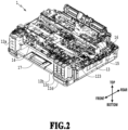
- Fig. 2 is a perspective view of an internal configuration of the liquid ejecting apparatus 1 illustrated in Fig. 1 .
- the liquid ejecting apparatus 1 includes a conveyance roller 13 used to convey the print medium (not illustrated), a carriage 15 provided with a print head 14 configured to eject the liquid, and a carriage motor 16 used to drive the carriage 15.
- the print medium is not limited to a particular medium as long as an image can be formed on the medium with the liquid ejected from the print head 14.
- paper, cloth, the label surfaces of optical discs, plastic sheets, OHP sheets or the like can be given as print media.
- the liquid is stored in the liquid tanks 12 and is supplied to the print head 14 via a liquid distribution passage 17 to be ejected from the print head 14.
- inks of four colors for example, cyan, magenta, yellow, and black
- four liquid tanks 12a to 12d for the respective colors that store the inks of the respective colors are provided as the liquid tanks 12.
- alphabets are added at the ends, for example, liquid tanks 12a to 12d.
- the liquid tank is referred to as the liquid tank 12.
- the liquid tanks 12a to 12d for the respective colors are arranged in a front face portion of the liquid ejecting apparatus 1 inside the case 11.
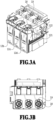
- Fig. 3A is an example of an enlarged perspective view of a portion of the liquid ejecting apparatus 1 illustrated in Fig. 1 in which the liquid tanks 12b to 12d are housed
- Fig. 3B is a plan view corresponding to the perspective view illustrated in Fig. 3A
- Each liquid tank 12 includes a liquid tank main body 121 used to store the liquid and a communication flow passage 122 communicating with a liquid storage chamber in the liquid tank main body 121.
- the liquid tank 12 includes a tank cover 123 (see Fig. 2 ) configured to be attachable to cover the communication flow passage 122 and seal the storage chamber in the liquid tank main body 121 in occasions other than an occasion of liquid replenishment.
- a discharge port of a liquid storage container 2 (see Fig. 4 ) is inserted into the communication flow passage 122 and the liquid is poured into the liquid tank 12.
- the liquid storage chamber is sealed with the tank cover 123 in occasions other than the occasion of liquid replenishment, and thus it is possible to reduce evaporation of the liquid in the liquid tank 12.
- the communication flow passage 122 includes two flow passages extending parallel to each other in the vertical direction in an interior thereof and is configured to allow the liquid in the liquid storage container 2 to be poured into the liquid tank by means of gas-liquid exchange.
- a socket 18 is provided in a portion of the liquid ejecting apparatus 1 where the discharge port of the liquid storage container 2 is to be inserted.
- the socket 18 is provided with protruding portions 19 protruding inward from an inner peripheral wall of the socket 18.
- the socket 18 is provided for each liquid tank 12, and the shapes of the protruding portions 19 vary among the sockets 18 to suppress erroneous insertion of the liquid container.
- the protruding portions 19 are rotationally symmetric by 180° with respect to the center axis of the communication flow passage 122.
- Fig. 4 is an elevation view of an outer appearance of the liquid storage container 2 which is a liquid container used to replenish the liquid tank 12 with the liquid.
- the liquid storage container 2 in Fig. 4 includes a bottle 21 that is a storage portion (main body portion) configured to store the liquid, a nozzle 22 coupled to the bottle 21, and a cap 23 attachable to and detachable from the nozzle 22.
- the nozzle 22 is a discharge port member having a function of an outlet for the case where the liquid stored in the bottle 21 is discharged.
- the cap 23 is a cover portion that is attached to the nozzle 22 to shield the interior of the liquid storage container 2 (specifically, the bottle 21) from the outside air.
- Methods of coupling the bottle 21 and the nozzle 22 to each other include a method of sealing a space between the bottle 21 and the nozzle 22 by inserting a flexible part, a method of forming both of the bottle 21 and the nozzle 22 with resin parts and welding the two parts together, and the like.
- the bottle 21 and the nozzle 22 may be an integral part.
- Fig. 5A illustrates an example of a part configuration view of the liquid storage container 2 illustrated in Fig. 4 .
- Fig. 5B is a cross-sectional view in which the parts in the part configuration view of the liquid storage container 2 illustrated in Fig. 5A are coupled to one another.
- the bottle 21 of the liquid storage container 2 includes a bottle welding portion 21a formed in an upper portion and a liquid storage portion 21b formed in a lower portion.
- the nozzle 22 includes a discharge port 22a through which the liquid is discharged, a nozzle thread portion 22b in which a male thread structure is formed on the outside, and a nozzle welding portion 22c in which a welding surface is formed on the inside or a bottom surface.
- Polyethylene (PE), polypropylene (PP), and the like can be given as examples of the material forming the bottle 21.
- Polyethylene (PE), polypropylene (PP), and the like can be given as the material forming the nozzle 22.
- the nozzle 22 is joined to the bottle 21 by welding the nozzle welding portion 22c to the bottle welding portion 21a. In the case where the bottle 21 and the nozzle 22 are joined by being welded to each other, the bottle 21 and the nozzle 22 are preferably made of the same type of material.
- a seal 24 having an opening, a valve 25 configured to open and close the opening of the seal 24, a spring 26 configured to bias the valve 25, and a holder 27 configured to fix the spring 26 are included inside the nozzle 22.
- the communication flow passage 122 of the liquid tank 12 is inserted into an opening of the nozzle 22 of the liquid storage container 2.
- the nozzle 22 of the liquid storage container 2 is provided with recess portions configured to engage with the protruding portions 19 of the socket 18 in the liquid ejecting apparatus 1, and the liquid storage container 2 is aligned in the case where the communication flow passage 122 is inserted into the opening of the nozzle 22. Then, the liquid in the liquid storage container 2 is supplied to the storage chamber of the liquid tank main body 121 via the communication flow passage 122 by means of hydraulic head difference.
- the seal 24 which is an orifice portion having an opening into which the communication flow passage 122 is to be inserted is arranged in a front end (upper end) of the nozzle 22. Then, the valve 25, which is a valve element of the liquid stop valve, is biased toward the opening with the spring 26, thereby the gap between the seal 24 and the valve 25 is closed, and the liquid storage container 2 is sealed.
- the spring 26 is used as a biasing mechanism, and the holder 27 fixed in an inner space of the nozzle 22 holds the spring 26.
- the seal 24 is formed of a flexible member made of rubber, elastomer, or the like. Polyethylene (PE), polypropylene (PP), and the like can be given as the material forming the valve 25.
- Stainless steel (SUS) and the like can be given as the material forming the spring 26.
- Polyethylene (PE), polypropylene (PP), and the like can be given as the material forming the holder 27.
- Welding and the like can be given as a method of fixing the holder 27 to the nozzle 22.
- the communication flow passage 122 is inserted into the nozzle 22 through the opening of the seal 24, thereby opening the valve 25. Then, as described above, the liquid in the liquid storage container 2 is supplied to the storage chamber of the liquid tank main body 121 via the communication flow passage 122 by means of hydraulic head difference. Note that, as illustrated in Fig. 5B , a protrusion 23f or the like may be provided in the cap 23 to open the valve 25 in cap-opening and cap-closing. In the case where the pressure in the liquid storage container 2 is higher than the outside air pressure, this configuration can suppress rushing of the liquid into the liquid tank 12 and overflowing of the liquid from the liquid tank 12 in supplying of the liquid to the liquid tank 12.
- a method of screwing the cap 23 to the nozzle 22 there is given a method of screwing the cap 23 to the nozzle 22.
- a method of screwing the cap 23 to the nozzle 22 by using the nozzle thread portion 22b in which a male thread structure is formed on the outside of the nozzle 22 and a cap thread portion 23a in which a female thread structure is formed on the inside of a lower portion of the cap 23.
- Attaching the cap 23 to the nozzle 22 causes a cap sealing portion 23b and part of the discharge port 22a to be fitted to each other and allows the liquid storage container 2 to be sealed.
- a cap 23 in which a male thread portion is formed and a nozzle 22 in which a female thread portion is formed may be used.
- the liquid storage container 2 may be maintained in a state where the valve 25 is opened by the protrusion 23f or the like.
- a fitting portion other than the sealing portion may be provided.
- a configuration such as an externally-fitted cover in which a cap 23 is fitted to the outside of a nozzle 22 or an internally-fitted cover in which a cap 23 is fitted to the inside of a nozzle 22.
- the nozzle 22 of the liquid storage container 2 in the embodiment is provided with the recess portions configured to engage with the protruding portions 19 of the socket 18 in the liquid ejecting apparatus 1.
- This configuration can prevent, in the case where a liquid tank 12 is replenished with liquid from a liquid storage container 2, erroneous pouring into a wrong liquid tank 12. Meanwhile, providing the recess portions in the nozzle 22 as described above and other factors increase the size of the nozzle 22 in some cases. In the case where the size of the nozzle 22 is increased, there is a possibility that impact resistance decreases and the liquid leaks from the sealed portion due to impact of dropping or the like. Accordingly, in the embodiment, a configuration that mitigates the impact is provided in the cap 23. Description thereof is given below.
- Figs. 6A to 6E are views of the structures of caps 23 in the embodiment.
- Fig. 6A illustrates a cross-sectional view of the cap 23 and a perspective view of the cap 23 from above.
- a circular groove structure 23e is arranged on the top face of the outside of the cap 23.
- the outside of the cap 23 refers to the side configured to be in contact with the outside air in the case where the cap 23 is attached to the nozzle 22.
- the groove structure 23e is continuously formed all around the center of the cap 23.
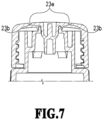
- Fig. 7 is a cross-sectional view of the cap 23 in a state where the cap 23 is attached to the nozzle 22. As illustrated in Fig. 7 , in the case where the fitting surface of the sealing portion (cap sealing portion 23b) extends in the vertical direction in the state where the liquid storage container 2 is standing upright, the groove structure 23e functions effectively against an impact in a direction perpendicular to the fitting surface.
- Figs. 6B to 6E are views of other examples of groove structures 23e.
- the groove structure 23e may be provided on the top face of the inside of the cap 23.
- the inside of the cap 23 refers to the side configured to be in contact with the nozzle 22 in the case where the cap 23 is attached to the nozzle 22.
- the groove structure 23e may be provided on both of the outside (groove structure 23e1) and the inside (groove structure 23e2) of the cap 23. In all cases, the groove structure 23e is provided between the outer periphery of the cap 23 and the sealing portion (cap sealing portion 23b) at which the cap 23 and the nozzle 22 are fitted to each other. Note that Fig.
- FIG. 6C illustrates an example in which the groove structure 23e2 on the inside of the cap 23 is arranged closer to the outer periphery of the cap 23 than the groove structure 23e1 on the outside of the cap 23.
- the groove structure 23e1 on the outside of the cap 23 may be arranged closer to the outer periphery of the cap 23 than the groove structure 23e2 on the inside of the cap 23.
- the shape of the groove structure 23e may be a polygonal shape as illustrated in Fig. 6D .
- the groove structure 23e does not have to be continuous all around the center as illustrated in Fig. 6E .
- the groove structure 23e may be discontinuously formed around the center of the cap 23.
- the width of the groove structure 23e may be uniform along the entire groove structure 23e or may be partially different.
- the depth of the groove structure 23e may also be uniform along the entire groove structure 23e or may be partially different.
- the groove structures 23e may have the same width and the same depth or may have different widths and different depths.
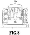
- Fig. 8 is a view of another example of the cap 23.
- a cylindrical structure 23c configured to be in contact with the nozzle 22 may be arranged directly below the groove structure 23e.
- the cylindrical structure 23c thus arranged can make the thickness of the cap 23 uniform, disperse an impact acting to an outer portion of the cap 23, and mitigate the impact propagating to the fitting portion between the nozzle 22 and the cap 23.
- the cylindrical structure 23c can suppress scattering of droplets to the outside that may occur in opening of the cap 23.
- the cap 23 including the groove structure 23e between the outer periphery of the cap 23 and the sealing portion between the nozzle 22 and the cap 23.
- Providing the groove structure 23e can mitigate the impact acting to a portion near the outer periphery of the cap 23 using the groove structure 23e, reduce the impact propagating to the sealing portion which is the contact portion, and suppress the leakage of the liquid.
- the liquid storage container may be a container used to replenish a liquid tank of any apparatus with liquid.
- the liquid storage container may store any kind of liquid.
Landscapes
- Ink Jet (AREA)
- Closures For Containers (AREA)
- Containers And Packaging Bodies Having A Special Means To Remove Contents (AREA)
Applications Claiming Priority (1)
| Application Number | Priority Date | Filing Date | Title |
|---|---|---|---|
| JP2020122250A JP7500313B2 (ja) | 2020-07-16 | 2020-07-16 | インク収容容器 |
Publications (2)
| Publication Number | Publication Date |
|---|---|
| EP3939795A1 EP3939795A1 (en) | 2022-01-19 |
| EP3939795B1 true EP3939795B1 (en) | 2024-09-11 |
Family
ID=76890912
Family Applications (1)
| Application Number | Title | Priority Date | Filing Date |
|---|---|---|---|
| EP21185113.4A Active EP3939795B1 (en) | 2020-07-16 | 2021-07-12 | Liquid storage container |
Country Status (4)
| Country | Link |
|---|---|
| US (2) | US11701890B2 (enExample) |
| EP (1) | EP3939795B1 (enExample) |
| JP (1) | JP7500313B2 (enExample) |
| CN (2) | CN113942309B (enExample) |
Families Citing this family (6)
| Publication number | Priority date | Publication date | Assignee | Title |
|---|---|---|---|---|
| JP2022018869A (ja) | 2020-07-16 | 2022-01-27 | キヤノン株式会社 | 液体収容容器 |
| JP7690828B2 (ja) * | 2021-09-17 | 2025-06-11 | セイコーエプソン株式会社 | インク補給容器 |
| WO2023054727A1 (ja) * | 2021-09-28 | 2023-04-06 | キヤノン株式会社 | 容器 |
| US12172447B2 (en) | 2021-09-30 | 2024-12-24 | Seiko Epson Corporation | Ink replenishment container |
| JP2023116195A (ja) * | 2022-02-09 | 2023-08-22 | 株式会社ソフイア | 遊技機 |
| JP2024088522A (ja) | 2022-12-20 | 2024-07-02 | キヤノン株式会社 | 液体吐出装置およびヘッドユニット |
Family Cites Families (74)
| Publication number | Priority date | Publication date | Assignee | Title |
|---|---|---|---|---|
| JPH0439180Y2 (enExample) * | 1987-08-12 | 1992-09-14 | ||
| EP1219447A3 (en) | 1996-11-15 | 2003-05-07 | Canon Kabushiki Kaisha | Container for liquid to be ejected |
| JP3295366B2 (ja) | 1997-02-19 | 2002-06-24 | キヤノン株式会社 | キャップ付き液体保持容器、キャップ及び液体保持容器 |
| JP3286210B2 (ja) | 1997-06-19 | 2002-05-27 | キヤノン株式会社 | インクタンク |
| DE60006883T2 (de) | 1999-04-05 | 2004-10-14 | Canon K.K. | Tintenabsorber und Tintenbehälter |
| JP3706782B2 (ja) | 1999-04-15 | 2005-10-19 | キヤノン株式会社 | 繊維積層体の製造方法、該方法によって製造された繊維積層体及び該繊維積層体を収納した液体収納容器、該容器を有した液体吐出ヘッドカートリッジ |
| JP3745161B2 (ja) | 1999-04-15 | 2006-02-15 | キヤノン株式会社 | 液体収納容器 |
| JP3647326B2 (ja) | 1999-08-24 | 2005-05-11 | キヤノン株式会社 | 液体収納容器、液体吐出機構およびインクジェット記録装置 |
| JP2001063079A (ja) | 1999-08-24 | 2001-03-13 | Canon Inc | 液体収納容器、液体吐出機構および液体吐出装置 |
| JP2001071522A (ja) | 1999-09-03 | 2001-03-21 | Canon Inc | 液体容器およびプリント装置 |
| US6164768A (en) | 1999-11-09 | 2000-12-26 | Illinois Tool Works Inc. | Adapter and mating bottle cap for coupling bottles to ink supplies |
| JP3809401B2 (ja) | 2001-07-27 | 2006-08-16 | キヤノン株式会社 | インクタンク |
| JP3977355B2 (ja) | 2004-06-07 | 2007-09-19 | キヤノン株式会社 | インクタンクおよび記録ヘッド |
| JP4585797B2 (ja) | 2004-06-07 | 2010-11-24 | キヤノン株式会社 | 液体供給装置 |
| JP4522245B2 (ja) | 2004-12-09 | 2010-08-11 | キヤノン株式会社 | 液体収容容器及びインクジェット記録装置 |
| JP4560401B2 (ja) | 2004-12-22 | 2010-10-13 | キヤノン株式会社 | インクタンクおよびインクジェット記録装置 |
| JP4994648B2 (ja) | 2005-11-30 | 2012-08-08 | キヤノン株式会社 | インクタンクおよびこれを用いるインクジェット記録装置 |
| JP2007152733A (ja) | 2005-12-05 | 2007-06-21 | Canon Inc | インクジェット記録装置および該装置用インクタンク |
| JP4750548B2 (ja) * | 2005-12-15 | 2011-08-17 | 東洋製罐株式会社 | 容器蓋 |
| US8313185B2 (en) | 2006-03-31 | 2012-11-20 | Canon Kabushiki Kaisha | Liquid container and liquid container package |
| JP4926538B2 (ja) | 2006-05-11 | 2012-05-09 | キヤノン株式会社 | 液体収納容器および記録装置 |
| JP4164519B2 (ja) | 2006-06-16 | 2008-10-15 | キヤノン株式会社 | インクジェット記録装置 |
| JP4942163B2 (ja) | 2006-08-03 | 2012-05-30 | キヤノン株式会社 | インク収納容器 |
| US7950790B2 (en) | 2006-09-11 | 2011-05-31 | Canon Kabushiki Kaisha | Ink container and ink jet recording apparatus |
| JP5224754B2 (ja) | 2006-11-29 | 2013-07-03 | キヤノン株式会社 | インクジェット記録装置 |
| JP4915320B2 (ja) * | 2007-09-21 | 2012-04-11 | ブラザー工業株式会社 | 液滴噴射装置 |
| JP5031506B2 (ja) | 2007-10-12 | 2012-09-19 | キヤノン株式会社 | インクタンクおよび記録装置 |
| BRPI0900903A2 (pt) | 2008-03-31 | 2010-04-06 | Canon Kk | recipiente de tinta para reter tinta, e, sistema de gravação a jato de tinta |
| JP5135125B2 (ja) * | 2008-08-28 | 2013-01-30 | 株式会社吉野工業所 | 塗布容器 |
| JP5550220B2 (ja) | 2008-08-29 | 2014-07-16 | キヤノン株式会社 | インクタンク |
| JP5729923B2 (ja) * | 2010-05-21 | 2015-06-03 | キヤノン株式会社 | 液体カートリッジおよび液体噴射装置 |
| JP5760399B2 (ja) | 2010-11-16 | 2015-08-12 | セイコーエプソン株式会社 | 液体補充容器 |
| EP2783862B1 (en) * | 2013-03-28 | 2019-05-08 | Brother Kogyo Kabushiki Kaisha | Liquid cartridge |
| EP3047975B1 (en) | 2013-09-18 | 2020-02-26 | Canon Kabushiki Kaisha | Ink cartridge, and inkjet printer |
| EP3047976B1 (en) | 2013-09-18 | 2019-11-06 | Canon Kabushiki Kaisha | Ink cartridge |
| US9738079B2 (en) * | 2013-11-29 | 2017-08-22 | Hitachi Industrial Equipment Systems Co., Ltd. | Replenishment container and inkjet recording device comprising same |
| JP6415114B2 (ja) | 2014-05-30 | 2018-10-31 | キヤノン株式会社 | 液体貯留ユニットとそれを用いた液体吐出装置及び液体貯留ユニットからの気泡の除去方法 |
| JP6395471B2 (ja) | 2014-06-27 | 2018-09-26 | キヤノン株式会社 | 液体収納容器及び液体吐出装置 |
| US9375938B2 (en) | 2014-06-27 | 2016-06-28 | Canon Kabushiki Kaisha | Ink cartridge and ink jet printing apparatus |
| US20180272722A1 (en) * | 2015-04-21 | 2018-09-27 | Bryan Murphy | Ink Tanks |
| JP6611564B2 (ja) | 2015-10-30 | 2019-11-27 | キヤノン株式会社 | 液体収納ボトルおよび液体収納ボトルのパッケージ |
| JP6498098B2 (ja) | 2015-10-30 | 2019-04-10 | キヤノン株式会社 | 記録装置および液体収容部材 |
| JP6716258B2 (ja) | 2016-01-08 | 2020-07-01 | キヤノン株式会社 | 記録装置、記録装置の制御方法、及びプログラム |
| US10005287B2 (en) | 2016-01-08 | 2018-06-26 | Canon Kabushiki Kaisha | Liquid ejection apparatus, liquid ejection head, and method of supplying liquid |
| JP6808324B2 (ja) | 2016-01-08 | 2021-01-06 | キヤノン株式会社 | 液体吐出記録装置及び液体吐出ヘッド |
| JP6611618B2 (ja) | 2016-01-08 | 2019-11-27 | キヤノン株式会社 | 記録装置、記録装置の制御方法、及びプログラム |
| US9914308B2 (en) | 2016-01-08 | 2018-03-13 | Canon Kabushiki Kaisha | Liquid ejection apparatus and liquid ejection head |
| JP2017209864A (ja) | 2016-05-25 | 2017-11-30 | キヤノン株式会社 | 液体吐出装置及び液体吐出ヘッド |
| CN111746140B (zh) | 2016-06-10 | 2022-05-13 | 精工爱普生株式会社 | 墨水补充容器 |
| CN111845094B (zh) | 2016-06-10 | 2022-01-11 | 精工爱普生株式会社 | 墨水补充容器 |
| CN207291315U (zh) | 2016-06-10 | 2018-05-01 | 精工爱普生株式会社 | 墨水补充容器和墨水补充系统 |
| JP6915304B2 (ja) | 2017-03-01 | 2021-08-04 | セイコーエプソン株式会社 | インク補給容器 |
| US10350901B2 (en) * | 2016-06-10 | 2019-07-16 | Seiko Epson Corporation | Ink bottle |
| US10308029B2 (en) | 2016-06-10 | 2019-06-04 | Seiko Epson Corporation | Liquid holding unit and liquid ejection device |
| JP6759876B2 (ja) | 2016-09-02 | 2020-09-23 | セイコーエプソン株式会社 | ボトルセット、ボトル |
| JP2018070162A (ja) | 2016-10-24 | 2018-05-10 | セイコーエプソン株式会社 | インク補給方法、インク補給容器、及びインクタンク |
| JP6903905B2 (ja) | 2016-12-12 | 2021-07-14 | 凸版印刷株式会社 | 液ダレ防止キャップおよびその製造方法 |
| JP2018144239A (ja) | 2017-03-01 | 2018-09-20 | セイコーエプソン株式会社 | プリンター、インクボトル |
| JP2018149785A (ja) * | 2017-03-15 | 2018-09-27 | セイコーエプソン株式会社 | インク補給容器 |
| JP6992307B2 (ja) | 2017-07-31 | 2022-01-13 | セイコーエプソン株式会社 | インク補給容器 |
| JP6972774B2 (ja) * | 2017-08-24 | 2021-11-24 | セイコーエプソン株式会社 | インク消費装置、接続機構、インク補充容器 |
| JP7267708B2 (ja) | 2017-10-13 | 2023-05-02 | キヤノン株式会社 | パッド電極を有する部材、インクカートリッジ、記録装置 |
| JP2019093669A (ja) | 2017-11-27 | 2019-06-20 | キヤノン株式会社 | 液体補充容器及び液体補充システム |
| JP2020033090A (ja) * | 2018-08-31 | 2020-03-05 | 株式会社吉野工業所 | ヒンジキャップ |
| JP7110038B2 (ja) | 2018-09-06 | 2022-08-01 | キヤノン株式会社 | 液体貯留容器および液体吐出装置 |
| JP7242231B2 (ja) | 2018-09-28 | 2023-03-20 | キヤノン株式会社 | パッド電極を有する部材、記録装置 |
| JP7224830B2 (ja) | 2018-09-28 | 2023-02-20 | キヤノン株式会社 | パッド電極を有する部材、インクカートリッジ、記録装置 |
| JP7154919B2 (ja) | 2018-09-28 | 2022-10-18 | キヤノン株式会社 | インクカートリッジ |
| JP7257856B2 (ja) | 2019-04-05 | 2023-04-14 | キヤノン株式会社 | 記録装置 |
| TWI684535B (zh) | 2019-04-18 | 2020-02-11 | 臺灣納米科技股份有限公司 | 墨水袋之接頭結構 |
| JP7599857B2 (ja) | 2020-07-08 | 2024-12-16 | キヤノン株式会社 | インクジェット記録装置 |
| JP7577473B2 (ja) | 2020-07-16 | 2024-11-05 | キヤノン株式会社 | インク収容容器 |
| JP2022018869A (ja) | 2020-07-16 | 2022-01-27 | キヤノン株式会社 | 液体収容容器 |
| JP7564660B2 (ja) | 2020-07-31 | 2024-10-09 | キヤノン株式会社 | 記録装置 |
-
2020
- 2020-07-16 JP JP2020122250A patent/JP7500313B2/ja active Active
-
2021
- 2021-07-08 US US17/370,942 patent/US11701890B2/en active Active
- 2021-07-12 EP EP21185113.4A patent/EP3939795B1/en active Active
- 2021-07-13 CN CN202110787352.6A patent/CN113942309B/zh active Active
- 2021-07-13 CN CN202310797046.XA patent/CN116587743A/zh active Pending
-
2023
- 2023-05-30 US US18/325,926 patent/US12168352B2/en active Active
Also Published As
| Publication number | Publication date |
|---|---|
| US20230302804A1 (en) | 2023-09-28 |
| JP2022018851A (ja) | 2022-01-27 |
| JP7500313B2 (ja) | 2024-06-17 |
| US20220016892A1 (en) | 2022-01-20 |
| CN113942309A (zh) | 2022-01-18 |
| CN113942309B (zh) | 2023-07-14 |
| US12168352B2 (en) | 2024-12-17 |
| EP3939795A1 (en) | 2022-01-19 |
| CN116587743A (zh) | 2023-08-15 |
| US11701890B2 (en) | 2023-07-18 |
Similar Documents
| Publication | Publication Date | Title |
|---|---|---|
| US11584132B2 (en) | Liquid storage container | |
| EP3939795B1 (en) | Liquid storage container | |
| US11760101B2 (en) | Liquid storage container | |
| US11007787B2 (en) | Ink refill container and ink refill system | |
| US9592675B2 (en) | Liquid fill container | |
| US12280601B2 (en) | Ink refill container and ink refill system | |
| US8454143B2 (en) | Liquid container, methods of assembling or disassembling liquid container, and image forming apparatus | |
| US11673405B2 (en) | Ink jet printing apparatus, ink tank and ink supply container | |
| JP6915304B2 (ja) | インク補給容器 | |
| JP2018140556A (ja) | インク補給容器及びインク補給システム | |
| JP7516625B2 (ja) | 液体吐出装置 | |
| WO2025187358A1 (ja) | 液体容器およびシステム | |
| WO2025057693A1 (ja) | インクボトルおよびシステム | |
| CN121084064A (zh) | 墨盒 |
Legal Events
| Date | Code | Title | Description |
|---|---|---|---|
| PUAI | Public reference made under article 153(3) epc to a published international application that has entered the european phase |
Free format text: ORIGINAL CODE: 0009012 |
|
| STAA | Information on the status of an ep patent application or granted ep patent |
Free format text: STATUS: THE APPLICATION HAS BEEN PUBLISHED |
|
| AK | Designated contracting states |
Kind code of ref document: A1 Designated state(s): AL AT BE BG CH CY CZ DE DK EE ES FI FR GB GR HR HU IE IS IT LI LT LU LV MC MK MT NL NO PL PT RO RS SE SI SK SM TR |
|
| STAA | Information on the status of an ep patent application or granted ep patent |
Free format text: STATUS: REQUEST FOR EXAMINATION WAS MADE |
|
| 17P | Request for examination filed |
Effective date: 20220330 |
|
| RBV | Designated contracting states (corrected) |
Designated state(s): AL AT BE BG CH CY CZ DE DK EE ES FI FR GB GR HR HU IE IS IT LI LT LU LV MC MK MT NL NO PL PT RO RS SE SI SK SM TR |
|
| GRAP | Despatch of communication of intention to grant a patent |
Free format text: ORIGINAL CODE: EPIDOSNIGR1 |
|
| STAA | Information on the status of an ep patent application or granted ep patent |
Free format text: STATUS: GRANT OF PATENT IS INTENDED |
|
| INTG | Intention to grant announced |
Effective date: 20240221 |
|
| GRAS | Grant fee paid |
Free format text: ORIGINAL CODE: EPIDOSNIGR3 |
|
| GRAA | (expected) grant |
Free format text: ORIGINAL CODE: 0009210 |
|
| STAA | Information on the status of an ep patent application or granted ep patent |
Free format text: STATUS: THE PATENT HAS BEEN GRANTED |
|
| AK | Designated contracting states |
Kind code of ref document: B1 Designated state(s): AL AT BE BG CH CY CZ DE DK EE ES FI FR GB GR HR HU IE IS IT LI LT LU LV MC MK MT NL NO PL PT RO RS SE SI SK SM TR |
|
| REG | Reference to a national code |
Ref country code: GB Ref legal event code: FG4D |
|
| REG | Reference to a national code |
Ref country code: CH Ref legal event code: EP |
|
| REG | Reference to a national code |
Ref country code: DE Ref legal event code: R096 Ref document number: 602021018555 Country of ref document: DE |
|
| REG | Reference to a national code |
Ref country code: IE Ref legal event code: FG4D |
|
| REG | Reference to a national code |
Ref country code: LT Ref legal event code: MG9D |
|
| PG25 | Lapsed in a contracting state [announced via postgrant information from national office to epo] |
Ref country code: NO Free format text: LAPSE BECAUSE OF FAILURE TO SUBMIT A TRANSLATION OF THE DESCRIPTION OR TO PAY THE FEE WITHIN THE PRESCRIBED TIME-LIMIT Effective date: 20241211 |
|
| REG | Reference to a national code |
Ref country code: NL Ref legal event code: MP Effective date: 20240911 |
|
| PG25 | Lapsed in a contracting state [announced via postgrant information from national office to epo] |
Ref country code: GR Free format text: LAPSE BECAUSE OF FAILURE TO SUBMIT A TRANSLATION OF THE DESCRIPTION OR TO PAY THE FEE WITHIN THE PRESCRIBED TIME-LIMIT Effective date: 20241212 Ref country code: FI Free format text: LAPSE BECAUSE OF FAILURE TO SUBMIT A TRANSLATION OF THE DESCRIPTION OR TO PAY THE FEE WITHIN THE PRESCRIBED TIME-LIMIT Effective date: 20240911 |
|
| PG25 | Lapsed in a contracting state [announced via postgrant information from national office to epo] |
Ref country code: BG Free format text: LAPSE BECAUSE OF FAILURE TO SUBMIT A TRANSLATION OF THE DESCRIPTION OR TO PAY THE FEE WITHIN THE PRESCRIBED TIME-LIMIT Effective date: 20240911 |
|
| PG25 | Lapsed in a contracting state [announced via postgrant information from national office to epo] |
Ref country code: LV Free format text: LAPSE BECAUSE OF FAILURE TO SUBMIT A TRANSLATION OF THE DESCRIPTION OR TO PAY THE FEE WITHIN THE PRESCRIBED TIME-LIMIT Effective date: 20240911 |
|
| PG25 | Lapsed in a contracting state [announced via postgrant information from national office to epo] |
Ref country code: HR Free format text: LAPSE BECAUSE OF FAILURE TO SUBMIT A TRANSLATION OF THE DESCRIPTION OR TO PAY THE FEE WITHIN THE PRESCRIBED TIME-LIMIT Effective date: 20240911 |
|
| PG25 | Lapsed in a contracting state [announced via postgrant information from national office to epo] |
Ref country code: ES Free format text: LAPSE BECAUSE OF FAILURE TO SUBMIT A TRANSLATION OF THE DESCRIPTION OR TO PAY THE FEE WITHIN THE PRESCRIBED TIME-LIMIT Effective date: 20240911 Ref country code: RS Free format text: LAPSE BECAUSE OF FAILURE TO SUBMIT A TRANSLATION OF THE DESCRIPTION OR TO PAY THE FEE WITHIN THE PRESCRIBED TIME-LIMIT Effective date: 20241211 |
|
| PG25 | Lapsed in a contracting state [announced via postgrant information from national office to epo] |
Ref country code: RS Free format text: LAPSE BECAUSE OF FAILURE TO SUBMIT A TRANSLATION OF THE DESCRIPTION OR TO PAY THE FEE WITHIN THE PRESCRIBED TIME-LIMIT Effective date: 20241211 Ref country code: NO Free format text: LAPSE BECAUSE OF FAILURE TO SUBMIT A TRANSLATION OF THE DESCRIPTION OR TO PAY THE FEE WITHIN THE PRESCRIBED TIME-LIMIT Effective date: 20241211 Ref country code: LV Free format text: LAPSE BECAUSE OF FAILURE TO SUBMIT A TRANSLATION OF THE DESCRIPTION OR TO PAY THE FEE WITHIN THE PRESCRIBED TIME-LIMIT Effective date: 20240911 Ref country code: HR Free format text: LAPSE BECAUSE OF FAILURE TO SUBMIT A TRANSLATION OF THE DESCRIPTION OR TO PAY THE FEE WITHIN THE PRESCRIBED TIME-LIMIT Effective date: 20240911 Ref country code: GR Free format text: LAPSE BECAUSE OF FAILURE TO SUBMIT A TRANSLATION OF THE DESCRIPTION OR TO PAY THE FEE WITHIN THE PRESCRIBED TIME-LIMIT Effective date: 20241212 Ref country code: FI Free format text: LAPSE BECAUSE OF FAILURE TO SUBMIT A TRANSLATION OF THE DESCRIPTION OR TO PAY THE FEE WITHIN THE PRESCRIBED TIME-LIMIT Effective date: 20240911 Ref country code: ES Free format text: LAPSE BECAUSE OF FAILURE TO SUBMIT A TRANSLATION OF THE DESCRIPTION OR TO PAY THE FEE WITHIN THE PRESCRIBED TIME-LIMIT Effective date: 20240911 Ref country code: BG Free format text: LAPSE BECAUSE OF FAILURE TO SUBMIT A TRANSLATION OF THE DESCRIPTION OR TO PAY THE FEE WITHIN THE PRESCRIBED TIME-LIMIT Effective date: 20240911 |
|
| REG | Reference to a national code |
Ref country code: AT Ref legal event code: MK05 Ref document number: 1722381 Country of ref document: AT Kind code of ref document: T Effective date: 20240911 |
|
| PG25 | Lapsed in a contracting state [announced via postgrant information from national office to epo] |
Ref country code: NL Free format text: LAPSE BECAUSE OF FAILURE TO SUBMIT A TRANSLATION OF THE DESCRIPTION OR TO PAY THE FEE WITHIN THE PRESCRIBED TIME-LIMIT Effective date: 20240911 |
|
| PG25 | Lapsed in a contracting state [announced via postgrant information from national office to epo] |
Ref country code: IS Free format text: LAPSE BECAUSE OF FAILURE TO SUBMIT A TRANSLATION OF THE DESCRIPTION OR TO PAY THE FEE WITHIN THE PRESCRIBED TIME-LIMIT Effective date: 20250111 Ref country code: PT Free format text: LAPSE BECAUSE OF FAILURE TO SUBMIT A TRANSLATION OF THE DESCRIPTION OR TO PAY THE FEE WITHIN THE PRESCRIBED TIME-LIMIT Effective date: 20250113 |
|
| PG25 | Lapsed in a contracting state [announced via postgrant information from national office to epo] |
Ref country code: SM Free format text: LAPSE BECAUSE OF FAILURE TO SUBMIT A TRANSLATION OF THE DESCRIPTION OR TO PAY THE FEE WITHIN THE PRESCRIBED TIME-LIMIT Effective date: 20240911 Ref country code: RO Free format text: LAPSE BECAUSE OF FAILURE TO SUBMIT A TRANSLATION OF THE DESCRIPTION OR TO PAY THE FEE WITHIN THE PRESCRIBED TIME-LIMIT Effective date: 20240911 |
|
| PG25 | Lapsed in a contracting state [announced via postgrant information from national office to epo] |
Ref country code: EE Free format text: LAPSE BECAUSE OF FAILURE TO SUBMIT A TRANSLATION OF THE DESCRIPTION OR TO PAY THE FEE WITHIN THE PRESCRIBED TIME-LIMIT Effective date: 20240911 Ref country code: AT Free format text: LAPSE BECAUSE OF FAILURE TO SUBMIT A TRANSLATION OF THE DESCRIPTION OR TO PAY THE FEE WITHIN THE PRESCRIBED TIME-LIMIT Effective date: 20240911 |
|
| PG25 | Lapsed in a contracting state [announced via postgrant information from national office to epo] |
Ref country code: CZ Free format text: LAPSE BECAUSE OF FAILURE TO SUBMIT A TRANSLATION OF THE DESCRIPTION OR TO PAY THE FEE WITHIN THE PRESCRIBED TIME-LIMIT Effective date: 20240911 Ref country code: PL Free format text: LAPSE BECAUSE OF FAILURE TO SUBMIT A TRANSLATION OF THE DESCRIPTION OR TO PAY THE FEE WITHIN THE PRESCRIBED TIME-LIMIT Effective date: 20240911 |
|
| PG25 | Lapsed in a contracting state [announced via postgrant information from national office to epo] |
Ref country code: IT Free format text: LAPSE BECAUSE OF FAILURE TO SUBMIT A TRANSLATION OF THE DESCRIPTION OR TO PAY THE FEE WITHIN THE PRESCRIBED TIME-LIMIT Effective date: 20240911 Ref country code: SK Free format text: LAPSE BECAUSE OF FAILURE TO SUBMIT A TRANSLATION OF THE DESCRIPTION OR TO PAY THE FEE WITHIN THE PRESCRIBED TIME-LIMIT Effective date: 20240911 |
|
| REG | Reference to a national code |
Ref country code: DE Ref legal event code: R097 Ref document number: 602021018555 Country of ref document: DE |
|
| PG25 | Lapsed in a contracting state [announced via postgrant information from national office to epo] |
Ref country code: DK Free format text: LAPSE BECAUSE OF FAILURE TO SUBMIT A TRANSLATION OF THE DESCRIPTION OR TO PAY THE FEE WITHIN THE PRESCRIBED TIME-LIMIT Effective date: 20240911 |
|
| PGFP | Annual fee paid to national office [announced via postgrant information from national office to epo] |
Ref country code: GB Payment date: 20250619 Year of fee payment: 5 |
|
| PLBE | No opposition filed within time limit |
Free format text: ORIGINAL CODE: 0009261 |
|
| STAA | Information on the status of an ep patent application or granted ep patent |
Free format text: STATUS: NO OPPOSITION FILED WITHIN TIME LIMIT |
|
| 26N | No opposition filed |
Effective date: 20250612 |
|
| PG25 | Lapsed in a contracting state [announced via postgrant information from national office to epo] |
Ref country code: SE Free format text: LAPSE BECAUSE OF FAILURE TO SUBMIT A TRANSLATION OF THE DESCRIPTION OR TO PAY THE FEE WITHIN THE PRESCRIBED TIME-LIMIT Effective date: 20240911 |
|
| PGFP | Annual fee paid to national office [announced via postgrant information from national office to epo] |
Ref country code: DE Payment date: 20250620 Year of fee payment: 5 |