EP3926610A2 - Élément de couplage magnétique pour un support d'informations - Google Patents
Élément de couplage magnétique pour un support d'informations Download PDFInfo
- Publication number
- EP3926610A2 EP3926610A2 EP21179604.0A EP21179604A EP3926610A2 EP 3926610 A2 EP3926610 A2 EP 3926610A2 EP 21179604 A EP21179604 A EP 21179604A EP 3926610 A2 EP3926610 A2 EP 3926610A2
- Authority
- EP
- European Patent Office
- Prior art keywords
- magnetic
- coupling
- information carrier
- coupling element
- holder
- Prior art date
- Legal status (The legal status is an assumption and is not a legal conclusion. Google has not performed a legal analysis and makes no representation as to the accuracy of the status listed.)
- Pending
Links
- 230000005291 magnetic effect Effects 0.000 title claims abstract description 306
- 230000008878 coupling Effects 0.000 title claims abstract description 117
- 238000010168 coupling process Methods 0.000 title claims abstract description 117
- 238000005859 coupling reaction Methods 0.000 title claims abstract description 117
- 239000000853 adhesive Substances 0.000 claims abstract description 38
- 230000001070 adhesive effect Effects 0.000 claims abstract description 38
- 238000000034 method Methods 0.000 claims abstract description 5
- 230000002093 peripheral effect Effects 0.000 claims description 26
- 239000004820 Pressure-sensitive adhesive Substances 0.000 claims description 7
- 238000004026 adhesive bonding Methods 0.000 claims description 5
- 230000003247 decreasing effect Effects 0.000 claims 1
- 230000008901 benefit Effects 0.000 description 14
- 229920003023 plastic Polymers 0.000 description 13
- 230000005294 ferromagnetic effect Effects 0.000 description 8
- 239000004744 fabric Substances 0.000 description 6
- 239000000463 material Substances 0.000 description 6
- 230000008859 change Effects 0.000 description 5
- XEEYBQQBJWHFJM-UHFFFAOYSA-N Iron Chemical compound [Fe] XEEYBQQBJWHFJM-UHFFFAOYSA-N 0.000 description 4
- 238000006073 displacement reaction Methods 0.000 description 4
- 229910052751 metal Inorganic materials 0.000 description 4
- 239000002184 metal Substances 0.000 description 4
- 239000012790 adhesive layer Substances 0.000 description 3
- 239000002390 adhesive tape Substances 0.000 description 3
- 238000001746 injection moulding Methods 0.000 description 3
- 230000000007 visual effect Effects 0.000 description 3
- 230000007423 decrease Effects 0.000 description 2
- 230000001419 dependent effect Effects 0.000 description 2
- 230000006870 function Effects 0.000 description 2
- 229910052742 iron Inorganic materials 0.000 description 2
- 239000010410 layer Substances 0.000 description 2
- 230000014759 maintenance of location Effects 0.000 description 2
- 239000000123 paper Substances 0.000 description 2
- 238000000926 separation method Methods 0.000 description 2
- 229910052782 aluminium Inorganic materials 0.000 description 1
- XAGFODPZIPBFFR-UHFFFAOYSA-N aluminium Chemical compound [Al] XAGFODPZIPBFFR-UHFFFAOYSA-N 0.000 description 1
- 230000001174 ascending effect Effects 0.000 description 1
- 239000011324 bead Substances 0.000 description 1
- 239000000969 carrier Substances 0.000 description 1
- 229920002678 cellulose Polymers 0.000 description 1
- 239000001913 cellulose Substances 0.000 description 1
- 230000001427 coherent effect Effects 0.000 description 1
- 239000002131 composite material Substances 0.000 description 1
- 238000010276 construction Methods 0.000 description 1
- 238000011161 development Methods 0.000 description 1
- 230000018109 developmental process Effects 0.000 description 1
- 239000003302 ferromagnetic material Substances 0.000 description 1
- 239000003292 glue Substances 0.000 description 1
- 238000004519 manufacturing process Methods 0.000 description 1
- 239000011159 matrix material Substances 0.000 description 1
- 230000000630 rising effect Effects 0.000 description 1
- 239000000243 solution Substances 0.000 description 1
- 238000005728 strengthening Methods 0.000 description 1
Images


Classifications
-
- G—PHYSICS
- G09—EDUCATION; CRYPTOGRAPHY; DISPLAY; ADVERTISING; SEALS
- G09F—DISPLAYING; ADVERTISING; SIGNS; LABELS OR NAME-PLATES; SEALS
- G09F3/00—Labels, tag tickets, or similar identification or indication means; Seals; Postage or like stamps
- G09F3/08—Fastening or securing by means not forming part of the material of the label itself
- G09F3/18—Casings, frames or enclosures for labels
- G09F3/20—Casings, frames or enclosures for labels for adjustable, removable, or interchangeable labels
- G09F3/207—Casings, frames or enclosures for labels for adjustable, removable, or interchangeable labels in the form of a badge to be worn by a person
-
- G—PHYSICS
- G09—EDUCATION; CRYPTOGRAPHY; DISPLAY; ADVERTISING; SEALS
- G09F—DISPLAYING; ADVERTISING; SIGNS; LABELS OR NAME-PLATES; SEALS
- G09F21/00—Mobile visual advertising
- G09F21/02—Mobile visual advertising by a carrier person or animal
- G09F21/023—Mobile visual advertising by a carrier person or animal fixed on clothing
-
- G—PHYSICS
- G09—EDUCATION; CRYPTOGRAPHY; DISPLAY; ADVERTISING; SEALS
- G09F—DISPLAYING; ADVERTISING; SIGNS; LABELS OR NAME-PLATES; SEALS
- G09F7/00—Signs, name or number plates, letters, numerals, or symbols; Panels or boards
- G09F7/02—Signs, plates, panels or boards using readily-detachable elements bearing or forming symbols
- G09F7/04—Signs, plates, panels or boards using readily-detachable elements bearing or forming symbols the elements being secured or adapted to be secured by magnetic means
-
- A—HUMAN NECESSITIES
- A44—HABERDASHERY; JEWELLERY
- A44C—PERSONAL ADORNMENTS, e.g. JEWELLERY; COINS
- A44C1/00—Brooches or clips in their decorative or ornamental aspect
-
- A—HUMAN NECESSITIES
- A44—HABERDASHERY; JEWELLERY
- A44D—INDEXING SCHEME RELATING TO BUTTONS, PINS, BUCKLES OR SLIDE FASTENERS, AND TO JEWELLERY, BRACELETS OR OTHER PERSONAL ADORNMENTS
- A44D2203/00—Fastening by use of magnets
-
- G—PHYSICS
- G09—EDUCATION; CRYPTOGRAPHY; DISPLAY; ADVERTISING; SEALS
- G09F—DISPLAYING; ADVERTISING; SIGNS; LABELS OR NAME-PLATES; SEALS
- G09F7/00—Signs, name or number plates, letters, numerals, or symbols; Panels or boards
- G09F7/18—Means for attaching signs, plates, panels, or boards to a supporting structure
- G09F2007/1852—Means for attaching signs, plates, panels, or boards to a supporting structure for fastening magnetically or by suction or the like
Definitions
- the invention relates to a magnetic coupling element for an information carrier and a magnetic holder or an information carrier holder with such a coupling element and a method for assembling such a coupling element.
- this information carrier is a name tag or the like, e.g. B. in the form of a correspondingly designed as a name tag information plate or a change holder for a name tag.
- Holders for name badges are well known and are offered in large numbers. Often these are simple pins or so-called combination clips, such as those used for. B. in the utility model DE 20 2005 015 325 U1 to be discribed.
- holders have also been offered that are based on a magnetic fastening principle. These include a magnetic element on the back of the name tag and a magnetic element which is separated from the holder and placed in an item of clothing, e.g. B. a shirt or jacket pocket or behind a lapel or the like, can be introduced. The two magnetic elements are then brought into contact with one another, so that the fabric of the garment is clamped between these two magnetic elements. The magnetic force between the magnetic elements ensures that the name badge is held in place.
- the magnetic elements In order to increase the magnetic adhesive force, the magnetic elements often comprise two magnets arranged next to one another, which are sometimes arranged with different polarity.
- such a solution sometimes increases the risk of the nameplate falling off, since the (smaller) magnets move even more easily with respect to the other magnetic element when they are turned and the attraction force decreases significantly when one of the magnets is no longer properly seated.
- the invention has for its object to provide a magnetic coupling element or a magnetic holder for an information carrier, for. B. to provide a name tag, which can be attached to an item of clothing as securely as possible against rotation.
- a coupling element (also referred to herein as a “magnetic coupling element”) according to the invention is used for fastening, i. H. a detachable coupling, an information carrier on an item of clothing, usually in conjunction with an additional magnetic element.
- information carrier means an element which is intended to be worn on an item of clothing and to contain information such as the name, a certain function, a task area, foreign language skills, etc. about the person wearing the information carrier. This can be an information disc, e.g. B. an engraved or printed name badge, or a change holder, information signs, z. B. made of cardboard, or electronic name badges to record.
- the coupling element has an information carrier side for fastening an information carrier to the coupling element and a coupling side facing away therefrom for releasably coupling the coupling element to an item of clothing with the aid of at least two interacting magnetic elements.
- the coupling element comprises a holder body and one of the magnetic elements, which is referred to below as the “first magnetic element”.
- the holding body is preferably neither permanently magnetic nor ferromagnetic and is preferably made of plastic and / or cellulose materials.
- a preferred mounting body can be manufactured inexpensively from plastic in an injection molding process, for example.
- the advantage of a non-magnetic holding body is that a second magnetic element (e.g. a holding magnet) is automatically "centered" in it on the first magnetic element, so that with a central arrangement of a correspondingly dimensioned first magnetic element, there is a gap on all sides for the fabric of the garment, for example remains free.
- Advantages of a mounting body made of plastic are thus in the better orientation and locking of a holding magnet, in a cost-effective production, in the multitude of design options and a low weight.
- magnetic includes the fact that the corresponding element can have the property of a magnet (permanent magnetic), that is to say things, e.g. B. made of iron, can attract magnetically, and can alternatively have the property of being passively attracted by a magnet (ferromagnetic).
- a magnet permanent magnetic
- the terms "permanent magnet” or “magnet” are used for an element that generates a magnetic field in its environment, and "ferromagnetic” for an element that is not designed as a magnet, i.e. does not generate its own magnetic field as intended , but can be attracted by a magnet.
- Magnetic element in the context of the invention means an element which is magnetic, that is to say permanently magnetic and / or ferromagnetic. In the case in which a permanent magnetic element and a ferromagnetic element are in magnetic contact, i.e.
- first magnetic element nor the second magnetic element need to be a single coherent body (although this embodiment is preferred for the first magnetic element in the holder body), it can also be formed from a collection of magnetic elements that are separated exist from each other or are embedded in a (non-magnetic) matrix, e.g. B. a plastic body.
- the first magnetic element should be assigned all components which are intended to be attracted by a second magnetic element when the coupling element is attached to an item of clothing, i.e. H. all magnetic elements located in the interior of the mounting body when the magnetic coupling element is assembled as intended.
- the first magnetic element is preferably ferromagnetic (and therefore not permanently magnetic), the holder body being particularly preferably non-magnetic.
- the entire coupling element is therefore preferably not permanently magnetic.
- the holder body is connected or connectable to the first magnetic element and shaped such that a magnetic adhesive surface for magnetic coupling with at least a second of the magnetic elements is formed on the coupling side.
- the “magnetic adhesive surface” can be the surface of the first magnetic element properly connected to the holding body.
- the first magnetic element is surrounded by a thin layer of a material to protect it from external influences.
- the surface of this layer is regarded as a magnetic adhesive surface.
- the magnetic adhesive surface is therefore the surface on which a second magnetic element rests when it is fastened as intended.
- the magnetic adhesive surface is located at least partially within a, preferably rectangular, inner area.
- This inner area is delimited on at least two, preferably opposite, edges along the magnetic adhesive surface by a respective delimitation wall projecting beyond the magnetic adhesive surface, preferably at a distance from this magnetic adhesive surface.
- the boundary walls are preferably designed to be steep on the side facing the magnetic adhesive surface and in particular have sections which protrude perpendicularly in the direction of the coupling side. With regard to these delimitation walls, this inner area can in particular be viewed as a depression in the holder body.
- the magnetic adhesive surface is therefore within the inner area, which is delimited on at least two edges by the boundary walls protruding beyond the magnetic adhesive surface. These edges (and preferably also the boundary walls) preferably run parallel to or at an angle to one another.
- the holding body can also include the first magnetic element, so that both elements are present in one piece as a metal part or as a composite.
- the holder body can correspond to the first magnetic element and is then shaped in such a way that a magnetic adhesive surface is formed on the coupling side for coupling to the second of the magnetic elements, which magnetic adhesive surface is at least partially within an inner area that is at least two edges along the Magnetic adhesive surface is limited in each case by a boundary wall projecting beyond the magnetic adhesive surface, e.g. B.
- the holding body forming the first magnetic element is shaped in the form of a magnetic U-profile (whereby the U-legs can each form a boundary wall and the U-web is the magnetic surface) or a "metal tub" or the like.
- the boundary walls partially run around the inner area, preferably on at least two sides, particularly preferably on three sides, and protrude upward from the information carrier side, that is, in the direction facing away from the information carrier side. Even if the boundary walls can definitely be curved, it is particularly preferred that they are straight, since this straight shape is particularly advantageous for security against rotation. Even if the boundary walls can be elastic, they are preferably made of plastic and are preferably rigid (in particular the modulus of elasticity is greater than 1 GPa and preferably less than 20 GPa).
- the boundary walls preferably run parallel to or at an angle to one another, in particular following the edges.
- the boundary walls are preferably straight. In principle, however, they could also be curved or have straight and curved passages. In the case of curved boundary walls, these advantageously run in such a way that they intersect or touch at an angle (at least in the case of an advanced course with separate boundary walls) so that they do not lie on the same (and in particular not a concentric) circular arc.
- the boundary walls therefore do not run on a circular path enclosing the magnetic adhesive surface or enclose the magnetic adhesive surface neither completely nor partially on a circular path (at least not the side facing the magnetic adhesive surface).
- This configuration of the mounting body provides, on the one hand, very good security against rotation and security against displacement, depending on the configuration in two, three or four directions, made possible in use, as the fabric is well enclosed between the second magnetic element and the towering walls in the interior.
- the holder body is preferably made in one piece from plastic in an injection molding process.
- a magnet which is used as a counterpart when attaching the coupling element to an item of clothing does not necessarily have to be part of the invention, since basically any magnet can be used initially.
- a simple iron plate or a magnetic element of clothing could also serve as a counterpart.
- the second magnetic element is not part of the magnetic coupling element per se, but rather forms a magnet holder according to the invention together with it.
- a magnet holder according to the invention is used for the detachable coupling of an information carrier to an item of clothing and comprises both a coupling element according to the invention and a second magnetic element which can be separated from this magnetic coupling element as intended.
- at least one of the magnetic elements is permanently magnetic, preferably at least the second magnetic element, which in this case could also be referred to as a "holding magnet”.
- the respective other magnetic element can also be permanently magnetic, the polarities of the magnets then having to be aligned in such a way that the two magnetic elements can attract each other.
- the coupling element ensures good security against rotation, since an item of clothing clamped between the first and second magnetic element is forced into folds by the boundary walls.
- the delimitation walls protrude beyond the magnetic adhesive surface and are (thus) shaped in such a way that a jammed item of clothing is forced into said folds through the delimitation walls.
- the coupling element and the second magnetic element are preferably shaped and dimensioned in relation to one another in such a way that, when the second magnetic element adheres to the magnetic adhesive surface in the inner region of the coupling element (without a jammed piece of clothing), a rotation of the second magnetic element relative to the coupling element about an axis perpendicular to Magnetic surface at least limited, z. B. because the second magnetic element then abuts at least one of the boundary walls.
- the second magnetic element is particularly preferably shaped relative to the coupling element or its inner area in such a way that it can be rotated less than 10 °, preferably less than 5 °, particularly preferably less than 1 ° (without a trapped item of clothing). although there should still be some play inside in order to provide enough space for the fabric of a jammed garment.
- An information carrier holder is suitable for attachment to an item of clothing and comprises an information carrier, e.g. B. as mentioned a change holder or an information disc or an electronic sign and a magnetic coupling element attached thereto according to the invention.
- the information carrier holder preferably additionally comprises a second magnetic element, that is to say would comprise a magnetic holder according to the invention as a whole.
- the two components "holder body” and “first magnetic element” of the magnetic coupling element of the information carrier holder can, for. B. glued together directly and / or the first magnetic element is positively held in the holder body.
- the components can also initially be present separately and only by attachment to, for. B. gluing on, an information carrier can be assembled.
- a first magnetic element is first attached to a rear side of an information carrier. This is preferably done by gluing, for example by applying glue or by using a double-sided adhesive tape.
- the magnetic element is then coupled to the holding body, whereby the magnetic coupling element is formed.
- the coupling can, as will be explained later, preferably take place by introducing it into a recess in the holding body and particularly preferably by latching or clamping the magnetic element in the recess.
- the holding body is then preferably not connected directly to the information carrier, but rather indirectly via the first magnetic element. A very simple assembly of the information carrier on the coupling element is thus possible.
- a holder body according to the invention for a magnetic coupling element should accordingly have a receiving area, preferably a suitable recess, for receiving the first magnetic element.
- This receiving area or the recess is preferably arranged in the interior area, particularly preferably in the center of the interior area, as will be shown later.
- an “information carrier” in the present sense is an element which is intended to be worn on an item of clothing and to display information about the person wearing the information carrier.
- a flat element can be referred to here as an information carrier which carries (preferably visual) information or can be provided with information.
- an information disc which can preferably be made of metal, in particular aluminum, or plastic. It can itself have the visual information (e.g. engraved and / or printed), but can theoretically also initially be present as a plate without information, at least if it can be written on or can serve as a holder for attaching a further information plate.
- a change holder is preferably at least partially transparent and in particular made of plastic and designed in such a way that it can in turn receive or hold an information plate or an information plate, for example made of cardboard or paper, and display it in a visible manner.
- an interchangeable holder can comprise a transparent cover into which an information label can be inserted and / or clamped.
- Another possibility for an information carrier would be a small display on which information is presented electronically.
- the information carrier can definitely be formed by means of a round or rounded surface or can have a general polyhedral shape, rectangular information carriers are preferred (possibly with rounded corners). Since the information carrier should be designed in such a way that it can be worn (comfortably) on the body, it is preferred that its length or its diameter is smaller than 20 cm, preferably smaller than 12 cm, in particular smaller than 8 cm. Since it is often supposed to carry visual information, e.g. B. writing that should be readable for other people, it is preferred that its length or its diameter is greater than 2 cm, preferably greater than 4 cm. Its width is preferably smaller than its length, the length to width ratio preferably being greater than 1.1, in particular greater than 1.7. However, the ratio is preferably less than 4, particularly preferably less than 2. For example, in the case of a rectangular shape, the length to width ratio is 7.5 cm to 4.1 cm or it corresponds to the golden ratio.
- the information carrier should expediently have a larger area than the coupling element or its mounting body in order to conceal this visually well.
- the holding body of the coupling element can be designed in different ways. What is important here is a shape that largely prevents excessive rotation of the second magnetic element with respect to the first rotary element.
- the boundary walls are preferably at least 3 mm, particularly preferably at least 5 mm, higher than the magnetic surface at a highest point. This is used to ensure that clothing material can be effectively clamped, and thus to a particularly good anti-twist retention on an item of clothing.
- the magnetic adhesive surface is preferably surrounded by a, preferably rectangular, peripheral area.
- This peripheral area is an area of the mounting body in which the boundary walls extend.
- the peripheral area thus surrounds the inner area, the boundary walls in the peripheral area partially running around this inner area, preferably on at least two sides.
- the boundary walls could run around the inner area on all four sides, i. H. the holder body forms a kind of "tub". Since it is advantageous if the magnetic force between the magnetic elements is relatively high, it is preferred in this case if the second magnetic element has a suitable engagement element, for example a widened surface on the side facing away from the first magnetic element to form a sufficiently wide grip edge to be able to grasp the second magnetic element well and pull it upwards away from the first magnetic element.
- a suitable engagement element for example a widened surface on the side facing away from the first magnetic element to form a sufficiently wide grip edge to be able to grasp the second magnetic element well and pull it upwards away from the first magnetic element.
- the boundary walls in the peripheral area run around the inner area on three sides.
- the holder body in the peripheral area i.e. the area around the magnetic adhesive surface
- the peripheral area is formed so that it is lowered on at least one extension edge in relation to the boundary walls that a second magnetic element which adheres to the magnetic adhesive surface (i.e., in particular, is coupled directly to the coupling element without intervening Clothing material, if the information carrier holder is not in use, for example), can be pushed out to the side at the pull-out edge from the magnetic surface between the boundary walls.
- This configuration in the peripheral area enables, on the one hand, very good security against rotation and displacement, depending on the configuration in two, three or four directions, in use, since the material is well enclosed between the second magnetic element and the upstanding walls in the peripheral area.
- the second magnetic element can be easily removed from one another despite the high adhesive force of the magnetic elements when the second magnetic element is coupled directly to the coupling element, as is usually the case before use.
- the high adhesive force is, in turn, desirable for secure attachment to clothing during use.
- an information carrier holder, in particular a corresponding name badge is thus created, which or which is securely attached to clothing when in use and is nevertheless easy to handle.
- the mounting body is designed on at least one extension edge, in particular a front edge, in the periphery area such that a second magnetic element is at least partially lifted off the first magnetic element during the pushing out due to the shape of the mounting body.
- the peripheral area at the extension edge is particularly preferably designed to be inclined and / or stepped towards an outer edge of the holder body. The advantage here is that it is easier to separate the first and second magnetic elements.
- the peripheral area can preferably have a very low delimiting wall at the extension edge, which is preferably not higher than 2 mm and particularly preferably has a slope towards the magnetic surface.
- This wall can be designed completely as an incline or have an inclined surface. This incline is shaped in such a way that when the second magnetic element is pushed out, it is lifted.
- the holder body can therefore become thicker towards the edge at the extension edge, with its surface increasing towards the coupling side. This has the The advantage that the second magnetic element is raised a little when it is pushed out and thus separated a little from the first magnetic element.
- the holding body in the peripheral area is lowered at the extension edge to the magnetic holding surface or beyond (that is, below the plane of the magnetic holding surface).
- the holder body (in the peripheral region) is preferably flat at the extension edge, in particular it runs flat up to the edge, corresponding to the bottom of the inner region of the holder body.
- the holder body can also be designed in a sloping and / or stepped manner, descending towards the outer edge of the peripheral area or of the entire holder body. According to this preferred embodiment, the holder body becomes thinner at the extension edge towards the edge, its surface sloping towards the coupling side.
- the height of the boundary walls adjoining the extension edge decreases, starting from the side opposite the extension edge towards the extension edge, in particular continuously, the relevant limitation walls preferably tapering in a wedge shape towards the extension edge.
- a flat or sloping extension side has the advantage that the magnetic elements can be easily separated from one another. However, there is no special protection against displacement in the extension direction in the event of undesired impacts against the information carrier.
- a slightly rising extension side has the advantage that a good average is achieved between a simple separation of the magnetic elements and a shift protection in the extension view in the event of undesired impacts against the information carrier.
- the extension edge is located on one of the front edges, which is a preferred positioning, and there is a boundary wall on the opposite front edge, which is a preferred shape of the holder body, the height of at least one of the boundary walls of the longitudinal edges increases from the said opposite front edge (where it is preferably flush with the local boundary wall) up to the extension edge. It is preferably flush with the height of the extension edge.
- the holder body has a recess in the interior. This recess is preferably dimensioned in such a way that the first magnetic element can be fitted into it, particularly preferably at least partially in a form-fitting manner.
- This recess can be introduced from the coupling side of the mounting body or from the information carrier side. It is particularly preferably a recess in the form of an opening, i. H. that the recess extends from the coupling side to the information carrier side of the holder body.
- the first magnetic element forms when properly installed in the holder body with the bottom of the interior (that is, the environment around the recess) essentially a flat surface.
- “essentially” means in particular that the surface of the first magnetic element projects beyond the floor by less than 1 mm or is projected above the floor by less than 1 mm.
- the upper surface of the first magnetic element ends flush with the bottom of the inner region.
- the holder body may preferably have suitable holding elements to hold the first magnetic element, for. B. positively to hold in the recess of the holder body.
- the holder body preferably has at least one projection (as a holding element) in the side walls of the recess, e.g. B. a bead, an inner collar or an inwardly pointing projection or a bar or retaining rail formed in the holder body.
- the projection is preferably arranged or designed so that a into the Recess fitted first magnetic element (z. B. positively) is held by means of the projection in the holder body.
- a holder can also be done in that the first magnetic element is attached to the back of an information carrier with a fastening means, preferably in the form of at least one pressure-sensitive adhesive element or an adhesive layer (which points to clothing when used as intended). If the assembly is then carried out in such a way that the projection comes to rest in the recess between the magnetic element and the back of the information carrier, that is, engages between the magnetic element and the information carrier, a secure retention in the recess is ensured.
- the fastening means is particularly preferably a double-sided adhesive tape in order to ensure a certain distance between the magnetic element and the information carrier and thus for easier engagement of the projection.
- the projection is preferably close to or directly on the edge to the information carrier side of the mounting body on the inner walls of the recess and particularly preferably runs like a strip or rail at least along part of the information carrier side edges of the recess.
- An embodiment of the holder body that the first magnetic element in a recess of the holder body, for. B. is held by means of suitable holding elements and the attachment of the holder body to the information carrier is done indirectly by the fact that the information carrier is attached to the first magnetic element, can simplify the assembly and disassembly of the holder body on the information carrier, since then yes no direct attachment, for. B. gluing, the mounting body on the information carrier is more required.
- one of the components can be replaced relatively quickly if it is damaged.
- Such a structure can therefore also be seen as an independent idea regardless of whether the mounting body is equipped with the boundary walls.
- the coupling element can also have a fastening means, such as pressure-sensitive adhesive elements or an adhesive layer, for the information carrier on the holder body on the information carrier side.
- a fastening means such as pressure-sensitive adhesive elements or an adhesive layer
- the mounting body can be held on the information carrier solely by said form fit, without being directly attached to it.
- the projection does not run over the entire inner wall of the recess, in particular an area in the direction of the extension edge or the area at the two end edges being free of a projection.
- the recess is rectangular and there are strip-like or rail-like projections or retaining rails only on the inner walls of two opposite, longer edges of the recess, these projections only running in a partial area of the inner walls of the recess and one area, in particular the area in front of the extension edge is free of protrusions.
- This free area is preferably dimensioned so that a first magnetic element already attached to the information carrier rear can be pushed into the mounting body from the information carrier side behind the strip-like or rail-like projections and can be arranged in the recess as intended.
- the projections thus act as retaining rails.
- the magnetic element can thus be placed and "clamped” particularly easily in the recess.
- the inner wall of the recess is beveled towards the information carrier side on the ejecting edge on the information carrier side of the mounting body.
- the first magnetic element can also be held in the holder body in that it is inserted into the recess from the information carrier side and is held on the coupling side by a (then preferably very thin) wall or some other holding element, and against falling out toward the information carrier side it is ensured from the recess that the holder body itself is fastened to the rear side of the information carrier by means of at least one suitable fastening means, preferably in the form of a pressure-sensitive adhesive element or an adhesive layer.
- At least one of the magnet elements has at least two permanent magnets which are adjacent to one another and spaced apart from one another. They are therefore positioned in such a way that when the second magnetic element is properly positioned, they adhere to different areas of the magnetic adhesive surface (if they are part of the second magnetic element) or to the second magnetic element (if they are part of the first magnetic element).
- This has the advantage that twisting is made more difficult because two centers each generate a magnetic field.
- a two-sided connection of the magnets of the relevant magnetic element by means of a metal plate on the top and bottom is also preferred. This creates a strengthening of the magnetic field, which results in a greater holding force than with two individual small magnets.
- At least one permanent magnet is flat, with a length to width ratio of at least 1.5 to 1, in particular with a ratio of at least 2 to 1, so that it is longer than it is wide.
- Preferred magnets are round or elliptical in shape.
- a magnetic element preferably comprises a plastic body into which at least one permanent magnet is introduced.
- the magnet elements are designed in such a way that when the second magnet element comes into contact with the magnetic surface (which can be, for example, direct contact with the magnet elements with maximum coverage of the surfaces, i.e. full coverage), a magnetic force greater than 4 N acts between the magnetic elements, in particular a force greater than 8 N, particularly preferably greater than 10 N or even greater than 20 N, for example 25 N.
- a magnetic force greater than 4 N acts between the magnetic elements, in particular a force greater than 8 N, particularly preferably greater than 10 N or even greater than 20 N, for example 25 N.
- the second magnetic element cannot simply be separated from the first magnetic element. Separation is facilitated according to the invention by the extension edge described above.
- the second magnetic element can have a handle, a tab or an edge, for example in the form of a projection, which makes it easier to lift off.
- the holder body can be round or rounded on one side, but it is preferred for the security against rotation that it has at least one straight boundary wall.
- the information carrier side of the holder body preferably has the shape of a polyhedron, particularly preferably the shape of a rectangle (see above).
- the holder body has a rectangular base area with two opposite longitudinal edges and two shorter end edges (the longitudinal edges are therefore always longer than the end edges in this embodiment).
- a push-out edge is preferably located on a front edge.
- the length ratio of the longitudinal edges to the front edges is preferably greater than 1.5 to 1, in particular greater than 2 to 1.
- the longitudinal edges are therefore preferably at least 1.5 times as long as the front edges, which promotes a secure hold. If one considers absolute dimensions, the longitudinal edges are particularly preferably longer than 20 mm, in particular longer than 35 mm.
- the longitudinal edges should, however, be smaller than 100 mm, in particular smaller than 50 mm, for a comfortable wearing experience. These dimensions are advantageous for handling.
- the magnet holder (in particular the coupling element) is preferably designed in such a way that there is a clear distance ("spacing area") between the second magnetic element (centrally) arranged as intended on the magnetic adhesive surface and the boundary walls of the holder body of at least 0.1 mm, preferably at least 1 mm , particularly preferably at least 2 mm, but preferably at most 10 mm, particularly preferably at most 5 mm or even at most 4 mm.
- This clear distance is present at least when the magnet holder is not attached to an item of clothing, that is, when the second magnet element adheres directly to the magnetic surface. This has the advantage that when it is arranged on an item of clothing between the boundary walls of the holder body and a second magnetic element, there is sufficient space for the fabric of the item of clothing.
- the dimension of the second magnetic element of a magnet holder compared to the corresponding dimension of the inner area of the holding element is such that the second magnetic element is always 0.2 mm smaller, preferably at least 2 mm, particularly preferably at least 4 mm, but preferably at most 20 mm, particularly preferably at most 10 mm or even at most 8 mm.
- the distance between the corresponding boundary walls at the front edges in relation to the The length of the second magnetic element or at the longitudinal edges in relation to the width of the second magnetic element therefore preferably corresponds to the values mentioned above.
- the boundary walls of the holder body are preferably so high that they do not protrude beyond the second magnetic element when positioned as intended on the magnetic adhesive surface (that is, directly above the first magnetic element). This has the advantage that when the magnet holder is arranged on an item of clothing, it is more comfortable to wear.
- the underside (side facing the first magnetic element as intended) of the second magnetic element is (slightly) convex or its lower edges are rounded, the inner area of the holder body and in particular also the first magnetic element preferably having a correspondingly matching negative shape.
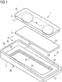
- Figure 1 shows a magnet holder 1 with a coupling element 10 according to the invention in a perspective view.
- the magnet holder 1 is used to hold an information carrier and together with it forms an information carrier holder 5 (in Figure 1 not shown, see this Figures 8 to 11 ).
- the coupling element 10 of the magnet holder 1 comprises a holder body 2 and a first magnet element 3.
- the coupling element 2 has an information carrier side 2g (in the Figure 1 below, which is why this direction is also referred to below as "below") on which the information carrier rests in the assembled state.
- the side shown above is the coupling side 2k, on which the coupling with a second magnetic element 4 can take place.
- the mounting body 2 has in a peripheral region 2p on the longitudinal edges and an end edge delimiting walls 2a, 2b which delimit an inner region 2d on three edges.
- a recess 2e here an opening 2e
- the recess has a circumferential projection 2f in the form of a projection educated. If the first magnetic element 3 is inserted into the recess 2e as intended, the boundary walls 2a, 2b protrude beyond the first magnetic element 3 and the inner region 2d.
- Such a mounting body 2 can be manufactured inexpensively from plastic in an injection molding process.
- the magnet holder 1 is completed by the second magnet element 4, which is cuboid here and comprises two laterally spaced apart permanent magnets 4a, which are arranged in a plastic body 4c.
- the second magnetic element 4 On its upper side, the second magnetic element 4 has a projection 4b as a grip edge 4b, which makes it easier to separate the second magnetic element 4 from the first magnetic element 3.
- the second magnetic element 4 is brought into magnetic contact with the first magnetic element 3 on the coupling side 2k.
- the second magnetic element 4 is usually magnetically coupled directly to the coupling element 10 or the first magnetic element 3.
- the surface of the first magnetic element 3 represents the magnetic adhesive surface 2m to which the second magnetic element 4 is coupled. It is conceivable that the first magnetic element 3 is arranged within a compartment of the holder body 2 (e.g. in a non-continuous recess that extends from the information carrier side into the holder body), with a surface of the holder body 2 on the coupling side the magnetic surface would represent 2m.
- the second magnetic element 4 is properly connected to the first magnetic element 3, there is a distance area 2q around the second magnetic element 4 until the peripheral area 2p begins, so that there is a clear distance between the second magnetic element 4 and the boundary walls 2a, 2b is present.
- the feature that the mounting body 2 is non-magnetic has the particular advantage that the second magnetic element 4 is automatically "centered" on the first magnetic element 3 so that a gap remains free on all sides for the fabric of an item of clothing. The magnet always lies flat.
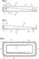
- Figure 2 shows the coupling element 10 according to Figure 1 in longitudinal section. It can be clearly seen that the first magnetic element 3 fits into the recess 2e in the inner region 2d of the holder body (and, as indicated by the arrows, is arranged there as intended). The first magnetic element 3 cannot fall down through the recess 2e, since it is held by the projections 2f (as holding elements 2f), which in this example run around the inner wall of the recess 2e. In the inserted state, the upper surface of the first magnetic element 3 is flush with the bottom of the inner area 2d, which does not always have to be the case, but is advantageous for connection to a further magnetic element.
- the boundary walls 2b arranged in the peripheral area 2p at the longitudinal edges and the one boundary wall 2a at one of the front edges protrude over the surface of the first magnetic element 3 (which is also the magnetic surface 2m here) in part clearly, which is a good thing and a secure hold on an item of clothing (see e.g. Figure 9 ).
- the end edge opposite the end edge with the boundary wall 2a in the peripheral area 2p is designed as an extension edge 2c in order to attach a second magnetic element 4 (see Fig. Figure 1 ), which adheres directly to the first magnetic element 3, to be pushed out laterally between the boundary walls 2b towards the push-out edge 2c and thus relatively easy to detach from the coupling element 10.
- a stepped shape can be seen here in the example at this push-out edge 2c, which has the shape of a bevel 2h towards the inside.
- This stage serves to activate a second magnetic element 4 (see Fig. Figure 1 ), which is located on the first magnetic element 3 and is displaced towards the push-out edge 2c to release it, while this displacement is slightly lifted from the first magnetic element 3. This lifting is made considerably easier by the incline 2h. This also serves as a slight protection against sliding in the direction of the open side.
- Figure 3 shows an example of a further preferred holder body 2 in longitudinal section. It is similar to the holder body 2 from Figure 2 with the difference that the projections 2f run only in the form of lateral retaining rails along part of the opposite longitudinal side walls of the recess 2e. They only extend here over approximately 2/3 of the length of the recess 2e, starting from that of the push-out edge 2c opposite end face.
- the information carrier side 2g of the holder body 2 has a bevel 2i at the bottom. This construction is used to push a flat magnetic element 3 from below into the recess 2e of the holder body 2 (see later on this Figure 10 ) and can also be pushed out again if necessary.
- Figure 4 shows the holder body 2 according to Figure 3 under supervision.
- the projections 2f can clearly be seen, which run only along part of the inner walls in the recess 2e.
- the orientation of the lateral support rails can be independent of the function of the extension edge, i. H. they could also extend starting from the end face of the recess pointing towards the ejection edge, and the information carrier side of the holder body has a bevel at the bottom on the opposite end face of the recess.
- Figure 5 shows another example of a holder body according to the invention in longitudinal section. It is similar to the bracket body Figure 2 with the difference that it has no step on its extension edge 2c, but is flat. In addition, projections 2f run only on the longitudinal edges and not on the front edges.
- Figure 6 shows another example of a holder body 2 according to the invention with a step shape in longitudinal section. It is similar to the bracket body Figure 5 with the difference that it is not flat at its extension edge 2c, but has a step shape with steps descending towards the outside.
- Figure 7 shows the example Figure 6 in perspective view. It can be clearly seen here that in the peripheral area 2p the two lateral boundary walls 2b slope down from the front boundary wall 2a, with which they are flush, to the level of the lower step at the extension edge 2c.
- the projection 2f in the recess 2e does not run on the front edges in this example, but only on the longitudinal edges, as in FIG Figures 5 and 6 is indicated.
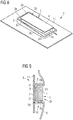
- FIG 8 shows an example of an information carrier holder 5 according to the invention in a perspective view.
- the information carrier holder 5 shown here includes in this Example of an information disc 11 as an information carrier 11, which is equipped with a magnetic holder 1 according to the invention.
- the magnet holder 1 comprises a holder body 2 (e.g. as shown in the preceding figures), a first magnetic element 3 (not visible here because it is located under the second magnetic element 4) and a second magnetic element 4.
- the holder body 2 is As explained in detail above with reference to the examples, designed so that the second magnetic element 4 is surrounded by a peripheral area 2p with boundary walls 2a, 2b and can be easily pushed out between the boundary walls 2a, 2b towards an extension edge 2c (see arrow). In the case of a (central) arrangement of the second magnetic element 4 as intended, there is a spacing area 2q between the second magnetic element 4 and the peripheral area 2p.
- Figure 9 shows schematically such an information carrier holder 5 according to the invention in cross section while it is attached to an item of clothing 6.
- the coupling element 10 is attached to the information disc 11 by means of a pressure-sensitive adhesive element 7 (preferably double-sided adhesive tape), in this particular example only its first magnetic element 3 and not the holder body 2.
- Two projections 2f can also be seen which hold the glued first magnetic element 3 as an undercut in a form-fitting manner in the holder body 2.
- the illustration also clearly shows how the material of the item of clothing 6 is clamped between the coupling element 10 and the second magnetic element 4 and the boundary walls 2b serve well as an anti-twist device.
- FIG 10 shows an exploded view of a further example of an information carrier holder 5 according to the invention.
- the information carrier holder 5 comprises an additional second magnetic element 4, so that it is equipped with a magnet holder 1 according to the invention.
- the information carrier 12 is designed as a typical interchangeable holder 12, into which, for example, an information label made of cardboard or paper can be pushed in from the side and clamped there.
- the interchangeable holder consists of a transparent plastic blank that has been folded over several times to form a transparent cover of suitable size. Such interchangeable holders 12 are well known.
- Figure 11 shows an example of the assembly of an information carrier holder 5 according to the invention using the example of the information carrier holder 5 from Figure 10 .
- the interchangeable holder 12 can be seen as an information carrier 12 (but it could also be an information disc 11), with the first one on its back Magnetic element 3 is glued on (e.g. by means of a pressure-sensitive adhesive element 7 as in Figure 9 ).
- a support body 2 which is configured such.
- each of the exemplary embodiments can optionally be provided with an information plate, an interchangeable holder for name tags or the like, or some other information carrier.
- the use of the indefinite article “a” or “an” does not exclude the possibility that the relevant features can also be present more than once.
Landscapes
- Physics & Mathematics (AREA)
- General Physics & Mathematics (AREA)
- Engineering & Computer Science (AREA)
- Theoretical Computer Science (AREA)
- Business, Economics & Management (AREA)
- Accounting & Taxation (AREA)
- Marketing (AREA)
- Adornments (AREA)
Applications Claiming Priority (1)
| Application Number | Priority Date | Filing Date | Title |
|---|---|---|---|
| DE102020116156.5A DE102020116156A1 (de) | 2020-06-18 | 2020-06-18 | Magnetisches Kopplungselement für einen Informationsträger |
Publications (2)
| Publication Number | Publication Date |
|---|---|
| EP3926610A2 true EP3926610A2 (fr) | 2021-12-22 |
| EP3926610A3 EP3926610A3 (fr) | 2022-03-30 |
Family
ID=76483152
Family Applications (1)
| Application Number | Title | Priority Date | Filing Date |
|---|---|---|---|
| EP21179604.0A Pending EP3926610A3 (fr) | 2020-06-18 | 2021-06-15 | Élément de couplage magnétique pour un support d'informations |
Country Status (2)
| Country | Link |
|---|---|
| EP (1) | EP3926610A3 (fr) |
| DE (1) | DE102020116156A1 (fr) |
Citations (1)
| Publication number | Priority date | Publication date | Assignee | Title |
|---|---|---|---|---|
| DE202005015325U1 (de) | 2005-09-22 | 2007-02-01 | "Durable" Hunke & Jochheim Gmbh & Co. Kg | Namensschild |
Family Cites Families (4)
| Publication number | Priority date | Publication date | Assignee | Title |
|---|---|---|---|---|
| DE19941421A1 (de) * | 1999-08-30 | 2001-03-01 | Praesenta Promotion Internat G | Namensschild-Set sowie Namensschild mit einem Befestigungsteil |
| DE202009005948U1 (de) | 2009-04-23 | 2009-07-09 | Bohn, Matthias | Vorrichtung zur Aufnahme eines kartenartigen Datenschildes |
| CA2876688C (fr) | 2014-06-20 | 2018-02-20 | Illen Products Ltd. | Dispositif de support d'affichage |
| DE202015002092U1 (de) | 2015-03-11 | 2015-04-08 | B.H. Mayer's Identitysign Gmbh | Kennzeichnungsanordnung |
-
2020
- 2020-06-18 DE DE102020116156.5A patent/DE102020116156A1/de active Pending
-
2021
- 2021-06-15 EP EP21179604.0A patent/EP3926610A3/fr active Pending
Patent Citations (1)
| Publication number | Priority date | Publication date | Assignee | Title |
|---|---|---|---|---|
| DE202005015325U1 (de) | 2005-09-22 | 2007-02-01 | "Durable" Hunke & Jochheim Gmbh & Co. Kg | Namensschild |
Also Published As
| Publication number | Publication date |
|---|---|
| EP3926610A3 (fr) | 2022-03-30 |
| DE102020116156A1 (de) | 2021-12-23 |
Similar Documents
| Publication | Publication Date | Title |
|---|---|---|
| DE4143004A1 (de) | Magnetischer haftverschluss | |
| DE4143005A1 (de) | Magnetischer haftverschluss | |
| DE202013105186U1 (de) | Etikett | |
| EP3926610A2 (fr) | Élément de couplage magnétique pour un support d'informations | |
| DE2656021C3 (de) | Briefordner zur Aufnahme von gelochtem Schriftgut | |
| EP3079140A2 (fr) | Dispositif d'ecran echangeable a double couche | |
| EP3537414A1 (fr) | Dispositif de maintien de support d'informations | |
| DE102011119442B4 (de) | Vorrichtung zur Halterung von Identifikationskarten | |
| DE4001989A1 (de) | Flexible strippe zum befestigen einer tuete an einem behaelter | |
| DE3817618C2 (fr) | ||
| EP0505697A2 (fr) | Support d'étiquette pour dos de classeur à lettres | |
| EP0640495B1 (fr) | Dispositif de fixation et article de forme plate avec dispositif de fixation | |
| DE102011117721A1 (de) | Magnetische Befestigungsvorrichtung | |
| DE19601601C1 (de) | Haltereinsatz für Klapphüllen von Datenträgern | |
| DE10130554B4 (de) | Schild, insbesondere Hinweis- und/oder Namensschild | |
| DE102015107418A1 (de) | Austauschbare Schildanordnung mit Doppellage | |
| DE19738440A1 (de) | Magnetischer Halter | |
| WO2022218513A1 (fr) | Dispositif de support pour supporter un dispositif électronique à l'intérieur d'une zone de réception pour le dispositif de support | |
| DE102021105954A1 (de) | Druck- oder Schreibwarenerzeugnis | |
| DE102013019283A1 (de) | Befestigungselement und Anordnung zum Aufhängen von Gegenständen. | |
| AT394280B (de) | Anzeigetafel | |
| DE202012010342U1 (de) | Befestigungselement und Anordnung zum Aufhängen von Gegenständen | |
| DE8127477U1 (de) | Informationsträger, insbesondere für Werbezwecke | |
| DE3210634A1 (de) | An der kleidung mitzufuehrender stempel | |
| DE202004015295U1 (de) | Kennzeichnungsvorrichtung für Fahrzeuge |
Legal Events
| Date | Code | Title | Description |
|---|---|---|---|
| PUAI | Public reference made under article 153(3) epc to a published international application that has entered the european phase |
Free format text: ORIGINAL CODE: 0009012 |
|
| STAA | Information on the status of an ep patent application or granted ep patent |
Free format text: STATUS: THE APPLICATION HAS BEEN PUBLISHED |
|
| AK | Designated contracting states |
Kind code of ref document: A2 Designated state(s): AL AT BE BG CH CY CZ DE DK EE ES FI FR GB GR HR HU IE IS IT LI LT LU LV MC MK MT NL NO PL PT RO RS SE SI SK SM TR |
|
| PUAL | Search report despatched |
Free format text: ORIGINAL CODE: 0009013 |
|
| AK | Designated contracting states |
Kind code of ref document: A3 Designated state(s): AL AT BE BG CH CY CZ DE DK EE ES FI FR GB GR HR HU IE IS IT LI LT LU LV MC MK MT NL NO PL PT RO RS SE SI SK SM TR |
|
| RIC1 | Information provided on ipc code assigned before grant |
Ipc: A44C 3/00 20060101ALI20220221BHEP Ipc: G09F 21/02 20060101ALI20220221BHEP Ipc: G09F 7/04 20060101ALI20220221BHEP Ipc: G09F 3/20 20060101AFI20220221BHEP |
|
| STAA | Information on the status of an ep patent application or granted ep patent |
Free format text: STATUS: REQUEST FOR EXAMINATION WAS MADE |
|
| 17P | Request for examination filed |
Effective date: 20220919 |
|
| RBV | Designated contracting states (corrected) |
Designated state(s): AL AT BE BG CH CY CZ DE DK EE ES FI FR GB GR HR HU IE IS IT LI LT LU LV MC MK MT NL NO PL PT RO RS SE SI SK SM TR |
|
| STAA | Information on the status of an ep patent application or granted ep patent |
Free format text: STATUS: EXAMINATION IS IN PROGRESS |
|
| 17Q | First examination report despatched |
Effective date: 20240319 |