EP3898479B1 - Aufzuganlage mit einer vorrichtung zum schaffen eines temporären schutzraumes - Google Patents
Aufzuganlage mit einer vorrichtung zum schaffen eines temporären schutzraumes Download PDFInfo
- Publication number
- EP3898479B1 EP3898479B1 EP19824311.5A EP19824311A EP3898479B1 EP 3898479 B1 EP3898479 B1 EP 3898479B1 EP 19824311 A EP19824311 A EP 19824311A EP 3898479 B1 EP3898479 B1 EP 3898479B1
- Authority
- EP
- European Patent Office
- Prior art keywords
- elevator
- shaft
- elevator system
- support element
- elevator car
- Prior art date
- Legal status (The legal status is an assumption and is not a legal conclusion. Google has not performed a legal analysis and makes no representation as to the accuracy of the status listed.)
- Active
Links
Images


Classifications
-
- B—PERFORMING OPERATIONS; TRANSPORTING
- B66—HOISTING; LIFTING; HAULING
- B66B—ELEVATORS; ESCALATORS OR MOVING WALKWAYS
- B66B5/00—Applications of checking, fault-correcting, or safety devices in elevators
- B66B5/0043—Devices enhancing safety during maintenance
- B66B5/005—Safety of maintenance personnel
- B66B5/0056—Safety of maintenance personnel by preventing crushing
-
- B—PERFORMING OPERATIONS; TRANSPORTING
- B66—HOISTING; LIFTING; HAULING
- B66B—ELEVATORS; ESCALATORS OR MOVING WALKWAYS
- B66B5/00—Applications of checking, fault-correcting, or safety devices in elevators
- B66B5/28—Buffer-stops for cars, cages, or skips
- B66B5/282—Structure thereof
Definitions
- the invention relates to an elevator system with a device for creating a temporary shelter.
- Elevator systems usually comprise an elevator car and a counterweight, which are arranged to move in opposite directions in an elevator shaft and are suitable for transporting people or goods. In order to keep such elevator systems operational, they must be serviced from time to time. For this purpose, it is necessary for a maintenance technician to carry out maintenance work in a shaft pit of the elevator shaft or on the elevator car in the shaft head of the elevator shaft. To ensure the safety of the maintenance technician, shelters are provided in the shaft head or in the shaft pit. These shelters are characterized by volumes with minimum dimensions in the shaft head or in the shaft pit, into which the elevator car should not penetrate during maintenance.
- a temporary protective space which can be arranged in the shaft pit or in the shaft head below or above the elevator car or the counterweight. If such a device is arranged in its maintenance position, the travel path of the elevator car is restricted in such a way that the protective space can be provided below the elevator car in the shaft pit or above the elevator car in the shaft head. In an operating position of this device, the elevator car can be moved completely within its travel path.
- WO 2008/002300 A1 discloses an elevator system according to the preamble of claim 1.
- the object is therefore to provide an elevator system with a device for creating a temporary protective space, wherein the device has small dimensions in its operating position.
- an elevator system with a device for creating a temporary protective space, the device comprising: a fastening element fixed in the elevator shaft, a support element connected to the fastening element, preferably directly connected, wherein the support element can be arranged within the elevator shaft in a maintenance position of the device such that a travel path of a traveling body belonging to the elevator system is restricted to form the temporary protective space, and an impact element connected to the support element, which is provided for direct mechanical contact with the traveling body in the maintenance position of the device, wherein the impact element is pivotally mounted on the support element.
- the elevator system has a traveling body that can be fully moved along a travel path in a normal operating mode of the elevator system.
- the at least one moving body in particular the elevator car, can move freely in the elevator shaft.
- the at least one moving body in particular the elevator car, can move freely in the elevator shaft.
- all floors connected by the elevator shaft can be served by the elevator car, including the top and bottom of these floors.
- the device installed in the elevator shaft can be arranged in its operating position during the normal operating mode of the elevator system.
- the travel path of the corresponding carriage is restricted by the device in such a way that, in particular, the lowest or the highest of these floors cannot be served by the lift car.
- the invention is based on the knowledge that the impact element usually has large dimensions for direct mechanical contact with the traveling body.
- this impact element In the maintenance position of the device, this impact element is arranged at an angle, preferably vertically, on the support element according to a main alignment of these components of the device. If this device is brought into its operating position, i.e. the support element is placed/laid down against a boundary wall of the elevator shaft, the angular arrangement of the impact element in relation to the support element according to the maintenance position results in a high dimension of the device protruding into the elevator shaft.
- the impact element can be arranged in the elevator shaft just as flat as the support element in the operating position of the device thanks to its ability to pivot on the support element.
- the pivoting ability can be achieved using hinges, for example.
- the support element can be detached from the fastening element in such a way that the device can be moved from its maintenance position into its operating position by means of this release.
- the support element and the impact element connected to the support element can be detached from the fastening element in their maintenance position in order to move the device into its operating position and can be stored in the elevator shaft independently of the fastening element during the normal operating mode of the elevator system.
- the elevator system can comprise a second fastening element, to which second fastening element the support element can be fastened in the operating position of the device.
- the second fastening element is preferably fixed directly to one of the boundary walls of the elevator system. It is advantageous that the support element and the impact element arranged thereon can thus be fixed in the elevator system are stowable in such a way that the travel path of the traveling body is only limited, if necessary, by the fastening element to which the support element can be fixed in the maintenance position.
- the support element is arranged pivotably on the fastening element.
- the advantage is that the support element can be pivoted in this way from the maintenance position to the operating position and vice versa. Accordingly, it is possible to transfer the parts of the device that can be fixed to the fastening element or the support element to the operating position of the device so that all components of the device can be stowed directly in the shaft pit or elsewhere, preferably in the elevator shaft.
- the support element can be locked into place on the fastening element and preferably the impact element on the support element in the maintenance position of the device, so that greater safety can be provided for the person in the protected space.
- the support element can be locked into place on the fastening element and preferably the impact element on the support element in the operating position of the device, for example to prevent a device that is fixed or can be fixed above the elevator car in the shaft head from entering the travel path of the elevator car that can be moved without restrictions and colliding with the elevator car.
- Safety can also be increased in this way for a device that can be arranged or is arranged on the elevator wall.
- the support element can be fixed to the second fastening element. For example, this can be achieved by snapping it into place. This enables the device or the support element to be securely fixed in the maintenance position of the device on the shaft floor or in the elevator shaft.
- the traveling body is formed by an elevator car of the elevator system or by a counterweight of the elevator system that can be moved in the opposite direction to the elevator car.
- a temporary protective space can be set up below the elevator car. If the device is arranged so that the travel path of the counterweight can be restricted by the maintenance position of the device, it can be achieved that the temporary protective space can be arranged above the elevator car in the shaft head.
- the impact element has a pivot axis mounted on the support element in such a way that the pivot axis is arranged in the operating position of the device between, on the one hand, a center line of the support element aligned in the main orientation of the support element and, on the other hand, a boundary wall of the elevator shaft.
- the boundary wall of the elevator shaft can be formed by a shaft wall of the elevator shaft, a shaft ceiling of the elevator shaft or a shaft floor of the elevator shaft.
- the fastening element is fixed to the shaft wall or to the shaft floor, preferably directly.
- the fastening element By fixing the fastening element to the shaft wall, it is possible to make the vertical dimension below the elevator car to the shaft floor as small as possible. This means that the shaft pit can have the smallest possible depth.
- the fastening element to the shaft floor it is possible to implement the device with the least possible material expenditure due to the forces of the traveling body acting on the device.
- FIG. 1 shows an elevator system 2 arranged in an elevator shaft 8.
- the elevator shaft comprises a shaft head 14 at its upper end and a shaft pit 9 at its lower end.
- the elevator shaft 8 is delimited by boundary walls 10.1, 10.2, 11, 17.
- the elevator shaft 8 is delimited laterally by at least one shaft wall 10.1, 10.2 and at the lower end of the shaft pit 9 by a shaft floor 11.
- the shaft head 14 can be delimited by a shaft ceiling 17.
- the elevator system 2 comprises at least one traveling body, in particular an elevator car 4, which elevator car 4 can be displaced without restriction along its travel path 15.
- the elevator system 2 can comprise a further traveling body - a counterweight 6 - which can be arranged or is arranged in the elevator shaft 8 so that it can move in the opposite direction to the elevator car 4.
- the counterweight 6 is arranged so that it can move along a travel path 16 that can be assigned to the counterweight 6.
- the counterweight 6 can be displaced in a correspondingly unrestricted manner along its travel path 16.
- the elevator car 4 and the counterweight 6 are connected by means of a support element 19.
- the support element 19 can be deflected by means of rollers 18 in a shaft head 14 of the elevator shaft 8.
- rollers 18 can be designed as a drive roller connected to a drive motor.
- the elevator system 2 comprises at least one device 12, 13 for creating a temporary protective space, wherein a first such device 12 shown can be fixed to the shaft floor 11 and a second such device 13 shown can be fixed to one of the shaft walls 10.1, 10.2.
- this device 12, 13 is arranged outside the travel path 15, 16 of the corresponding travel body 4, 6.
- the device 12, 13 is arranged outside the volume is the volume that can be occupied by the elevator car 4 or the counterweight 6 in the normal operating mode of the elevator system 2.
- the devices 12, 13 are spaced apart from the travel path 15, 16 of the corresponding travel body 4, 6 in their operating position.
- a device for creating the temporary protective space arranged above the elevator car 4 which can be arranged in the shaft head 14 as an alternative to the arrangement of the device 13 below the counterweight 6.
- Figure 2 shows the Figure 1 shown elevator system 2 with devices 12, 13 arranged in their maintenance position for creating the temporary protective space.
- the device 13' which can be arranged above the elevator car and which can be an alternative to the device 13 arranged below the counterweight is shown.
- the devices 12, 13, 13' for creating the temporary protective spaces 30', 30" are shown or arranged in their maintenance position.
- Each of these devices 12, 13, 13' comprises a fastening element 22 fixed or fixable in the elevator shaft 8, in particular on the shaft floor 11, on one of the shaft walls 10.1, 10.2 or on the shaft ceiling 17, a support element 24 connected to the fastening element 22, and an impact element 26 connected to the support element 24.
- the support element 24 is arranged in such a way that it protrudes from the shaft wall 10.2 or the shaft floor 11 that the support element 24 protrudes into the travel path 15, 16 of the traveling body 4, 6 and the impact element 26 is suitably positioned to restrict the travel path of the traveling body. Consequently, the travel path 15, 16 of the traveling body is restricted in the maintenance position of the device 12, 13, 13'.
- the impact element 26 is arranged in the maintenance position in such a way, preferably horizontally, that a lower surface of the traveling body (the elevator car shown; 4') can rest on it. Accordingly, the impact element 26 is provided for direct mechanical contact with the traveling body 4, 6 in the maintenance position of the device 12, 13, 13'.
- the lower surface of the elevator car 4 intended to strike the impact element 26 can, for example, be formed by a cross member of a frame of the elevator car 4.
- the fastening element 22 of the device 13 arranged below the counterweight can be fixed or fixable to the shaft floor 11.
- the device 13 can additionally have a stabilizing element 27.
- the stabilizing element 27 connects the support element 24 and the fastening element 22 in such a way that the statics of the device 13 fixed to the shaft wall 10.2 are ensured.
- An additional buffer element (not shown) can be arranged on the impact element 26 or on the moving body in such a way that contact of the moving body with the device 12, 13, 13' is dampened.
- the device for creating the temporary protective space 30" above the cabin roof 4" can be arranged in the shaft head 14 as an alternative to the arrangement in the shaft pit 9.
- the fastening element 22 of the device 13' arranged in the shaft head 14 can be fastened or can be fastened to the shaft ceiling 17 or to the shaft walls 10.1, 10.2 in the shaft head 14.
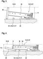
- the Figures 3 and 4 show devices 12, 13, 13' for creating a temporary shelter.
- the support elements 24 of the device 12, 13, 13' are directly connected to the fastening element 22 and pivoted in such a way that the device 12, 13, 13' does not restrict the travel path 15, 16 of the traveling body.
- Figure 3 shows an impact element 26 fixed to the support element 24 according to previously known State of the art. Accordingly, a maximum distance T1 of each component of the device 12, 13, 13' from the boundary wall 10.1, 10.2, 11 is formed.
- the in Figure 4 The unclaimed device 12, 13, 13' shown is shown in its operating position.
- the pivotable impact element 26 can therefore be pivoted on the support element 24 about a pivot axis S in the operating position of the device 12, 13, 13' in such a way that the main orientations of the support element 24 and the impact element 26 run in almost the same direction.
- a center line M of the support element 24 is shown, which runs parallel to the main alignment of the support element 24.
- the pivot axis S is arranged between the boundary wall 10.1, 10.2, 11, 17 and this center line M, so that the support element 24 or the device 12, 13, 13' is arranged closer to the boundary wall 10.1, 10.2, 11, 17 in its operating position. Accordingly, the maximum distance T2 of each component of the Figure 4 shown device 12, 13, 13' in its operating position is formed by the boundary wall 10.1, 10.2, 11, 17.
Landscapes
- Cage And Drive Apparatuses For Elevators (AREA)
- Maintenance And Inspection Apparatuses For Elevators (AREA)
Description
- Die Erfindung betrifft eine Aufzugsanlage mit einer Vorrichtung zum Schaffen eines temporären Schutzraumes.
- Aufzugsanlagen umfassen üblicherweise eine Aufzugskabine und ein Gegengewicht, welche gegenläufig in einem Aufzugsschacht verfahrbar angeordnet sind und zum Transport von Personen bzw. Gütern geeignet sind. Um solche Aufzugsanlagen betriebsfähig zu halten, müssen diese von Zeit zu Zeit gewartet werden. Zu diesem Zweck ist es erforderlich, dass ein Wartungstechniker in einer Schachtgrube des Aufzugsschachtes oder auf der Aufzugskabine im Schachtkopf des Aufzugsschachtes Wartungstätigkeiten ausführt. Um die Sicherheit des Wartungstechnikers zu gewährleisten, sind im Schachtkopf bzw. in der Schachtgrube Schutzräume vorgesehen. Diese Schutzräume sind durch Volumina mit Mindestabmessungen im Schachtkopf bzw. in der Schachtgrube gekennzeichnet, in welche die Aufzugskabine während der Wartung nicht eindringen soll.
- Es bestehen zudem Bestrebungen, die für den Betrieb der Aufzugsanlage notwendigen Dimensionen des Aufzugsschachtes so gering wie möglich zu gestalten. Das heißt, dass die Dimensionen des Aufzugsschachtes möglichst nur unwesentlich größer sind als die Dimensionen, welche die Aufzugskabine bzw. das Gegengewicht während einer Aufzugsfahrt annehmen können.
- Demzufolge ist der Raum in der Schachtgrube unterhalb einer Position der Aufzugskabine in ihrer im Normalbetriebsmodus untersten Stellung zu klein, um einen solchen Schutzraum ausbilden zu können. Das Gleiche gilt für einen auf der Aufzugskabine anzuordnenden Schutzraum im Schachtkopf.
- Zu diesem Zweck gibt es Vorrichtungen zum Schaffen eines temporären Schutzraumes, welche in der Schachtgrube oder im Schachtkopf unterhalb bzw. oberhalb der Aufzugskabine bzw. des Gegengewichtes anordenbar sind. Ist eine solche Vorrichtung in ihrer Wartungsstellung angeordnet, ist ein Verfahrweg der Aufzugskabine derart eingeschränkt, dass der Schutzraum unterhalb der Aufzugskabine in der Schachtgrube bzw. oberhalb der Aufzugskabine im Schachtkopf gegeben sein kann. In einer Betriebsstellung dieser Vorrichtung ist die Aufzugskabine vollständig innerhalb ihres Verfahrweges verfahrbar.
- Es bestehen Vorrichtungen, welche oberhalb/unterhalb der Aufzugskabine bzw. des Gegengewichtes fixierbar sind und ein Stützelement aufweisen, welches in der Wartungsstellung der Vorrichtung in den Verfahrweg der Aufzugskabine bzw. des Gegengewichtes eingeschwenkt ist. An diesem Stützelement ist üblicherweise eine Prallplatte angeordnet, welche für einen Kontakt mit der Aufzugskabine bzw. mit dem Gegengewicht vorgesehen ist und demnach mit entsprechend hohen Abmessungen ausgebildet ist. Derartige Vorrichtungen sind in
WO 2008/002300 A1 ,DE 20 2016 103556 U1 undES 2 597 810 A2 WO 2008/002300 A1 offenbart eine Aufzuganlage gemäß dem Oberbegriff des Anspruchs 1. - Es besteht daher die Aufgabe, eine Aufzugsanlage mit einer Vorrichtung zum Schaffen eines temporären Schutzraumes zu schaffen, wobei die Vorrichtung in ihrer Betriebsstellung geringe Abmessungen aufweist.
- Diese Aufgabe wird gelöst durch eine Aufzuganlage mit einer Vorrichtung zum Schaffen eines temporären Schutzraumes, die Vorrichtung umfassend: ein im Aufzugsschacht fixiertes Befestigungselement, ein mit dem Befestigungselement verbundenes, vorzugsweise direkt verbundenes, Stützelelement, wobei das Stützelement in einer Wartungsstellung der Vorrichtung derart innerhalb des Aufzugsschachtes anordenbar ist, dass ein Verfahrweg eines zur Aufzugsanlage gehörigen Fahrkörper zur Ausbildung des temporären Schutzraumes eingeschränkt ist, und ein mit dem Stützelement verbundenes Prallelement, welches in der Wartungsstellung der Vorrichtung für einen direkten mechanischen Kontakt mit dem Fahrkörper vorgesehen ist, wobei das Prallelement schwenkbar an dem Stützelement gelagert ist.
- Die Aufzugsanlage weist einen entlang eines Verfahrweges in einem Normalbetriebsmodus der Aufzugsanlage vollständig verfahrbaren Fahrkörper auf.
- Während eines solchen Normalbetriebsmodus ist der mindestens eine Fahrkörper, insbesondere die Aufzugskabine, uneingeschränkt im Aufzugsschacht verfahrbar. Das heisst, dass alle Stockwerke, welche der Aufzugsschacht verbindet, durch die Aufzugskabine bedienbar sind, einschliesslich des obersten und des untersten dieser Stockwerke. Demnach ist die im Aufzugsschacht installierte Vorrichtung während des Normalbetriebsmodus der Aufzugsanlage in ihrer Betriebsstellung anordenbar.
- Ist die im Aufzugsschacht installierte Vorrichtung hingegen in ihrer Wartungsstellung angeordnet, ist der Verfahrweg des entsprechenden Fahrkörpers durch die Vorrichtung derart eingeschränkt, dass insbesondere das unterste oder das oberste dieser Stockwerke nicht durch die Aufzugskabine bedienbar ist.
- Der Erfindung liegt die Erkenntnis zugrunde, dass das Prallelement üblicherweise große Abmessungen für den direkten mechanischen Kontakt mit dem Fahrkörper aufweist. In der Wartungsstellung der Vorrichtung ist dieses Prallelement gemäss einer Hauptausrichtung dieser Komponenten der Vorrichtung winklig, vorzugsweise senkrecht, am Stützelement angeordnet. Wird diese Vorrichtung in ihre Betriebsstellung verbracht, das heisst, das Stützelement an eine Begrenzungswand des Aufzugsschachtes angelegt/abgelegt, bewirkt die winklige gemäss der Wartungsstellung vorhandene Anordnung des Prallelementes bezüglich des Stützelementes eine hohe in den Aufzugsschacht ragende Abmessung der Vorrichtung.
- Um dennoch eine möglichst in ihrer Betriebsstellung wenig Raum beanspruchende Vorrichtung zu ermöglichen, ist das Prallelement in der Betriebsstellung der Vorrichtung mittels seiner Verschwenkbarkeit am Stützelement ebenso flach im Aufzugsschacht anordenbar wie das Stützelement. Die Verschwenkbarkeit kann beispielhaft mittels Scharnieren erreicht werden.
- Erfindungsgemäß ist das Stützelement vom Befestigungselement derart lösbar, dass die Vorrichtung mittels dieses Lösens von ihrer Wartungsstellung in ihre Betriebsstellung überführbar ist. Derart können das Stützelement und das mit dem Stützelement verbundene Prallelement in ihrer Wartungsstellung zum Verbringen der Vorrichtung in seine Betriebsstellung vom Befestigungselement gelöst werden und im Aufzugsschacht während des Normalbetriebsmodus der Aufzugsanlage unabhängig vom Befestigungselement gelagert werden.
- Demnach kann die Aufzugsanlage ein zweites Befestigungselement umfassen, an welchem zweiten Befestigungselement das Stützelement in der Betriebsstellung der Vorrichtung befestigbar ist. Das zweite Befestigungselement ist vorzugsweise unmittelbar an einer der Begrenzungswände der Aufzugsanlage fixiert. Von Vorteil ist, dass das Stützelement und das daran angeordnete Prallelement auf diese Weise so in der Aufzugsanlage verstaubar sind, dass der Verfahrweg des Fahrkörpers lediglich durch das Befestigungselement, an welchem das Stützelement in der Wartungsstellung fixierbar ist, gegebenenfalls eingeschränkt ist.
- Bei einer alternativen, nicht beanspruchten Ausführung einer Aufzugsanlage bzw. einer Vorrichtung ist das Stützelement schwenkbar an dem Befestigungselement angeordnet. Von Vorteil ist, dass das Stützelement auf diese Weise von der Wartungsstellung in die Betriebsstellung geschwenkt werden kann und umgekehrt. Demnach ist es möglich, die am Befestigungselement fixierbaren Teile der Vorrichtung bzw. das Stützelement in die Betriebsstellung der Vorrichtung zu überführen, dass alle Bestandteile der Vorrichtung direkt in der Schachtgrube oder an anderer Stelle vorzugsweise im Aufzugsschacht verstaubar sind.
- Vorzugsweise sind das Stützelement am Befestigungselement und vorzugsweise das Prallelement am Stützelement in der Wartungsstellung der Vorrichtung einrastend fixierbar, so dass eine höhere Sicherheit der im Schutzraum befindlichen Person gegeben sein kann. Darüber hinaus können das Stützelement am Befestigungselement und vorzugsweise das Prallelement am Stützelement in der Betriebsstellung der Vorrichtung einrastend fixierbar sein, um beispielhaft eine oberhalb der Aufzugskabine im Schachtkopf fixierte oder fixierbare Vorrichtung nicht in den Verfahrweg der uneingeschränkt verfahrbaren Aufzugskabine hineingelangen und mit der Aufzugskabine kollidieren zu lassen. Bei einer an der Aufzugswand anordenbaren oder angeordneten Vorrichtung kann derart ebenso die Sicherheit erhöht werden.
- Bei einer Weiterbildung der Aufzugsanlage bzw. der Vorrichtung ist das Stützelement an dem zweiten Befestigungselement fixierbar. Beispielhaft ist dies durch Einrasten erreichbar. Demnach ist eine sichere Fixierung der Vorrichtung bzw. des Stützelementes in der Wartungsstellung der Vorrichtung auf dem Schachtboden bzw. im Aufzugsschacht ermöglicht.
- Bei einer Weiterbildung der Aufzugsanlage ist der Fahrkörper durch eine Aufzugskabine der Aufzugsanlage oder durch ein gegenläufig zur Aufzugskabine verfahrbares Gegengewicht der Aufzugsanlage gebildet. Durch Einschränkung des Verfahrweges der Aufzugskabine bzw. durch eine Anordnung der Vorrichtung vorzugsweise unterhalb der Aufzugskabine ist ein solcher temporärer Schutzraum unterhalb der Aufzugskabine einrichtbar. Bei einer Anordnung der Vorrichtung, so dass durch die Wartungsstellung der Vorrichtung der Verfahrweg des Gegengewichtes einschränkbar ist, kann erreicht werden, dass der temporäre Schutzraum oberhalb der Aufzugskabine im Schachtkopf anordenbar ist.
- Bei einer Weiterbildung der Aufzugsanlage weist das Prallelement eine derart am Stützelement gelagerte Schwenkachse auf, dass die Schwenkachse in der Betriebsstellung der Vorrichtung zwischen einerseits einer in Hauptausrichtung des Stützelementes ausgerichteten Mittellinie des Stützelementes und andererseits einer Begrenzungswand des Aufzugsschachtes angeordnet ist. Mittels einer solchen Anordnung ist ein maximaler Abstand, welchen die Vorrichtung in ihrer Betriebsstellung von der Begrenzungswand einnimmt, minimierbar. Die Begrenzungswand des Aufzugsschachtes kann durch eine Schachtwand des Aufzugsschachtes, eine Schachtdecke des Aufzugsschachtes oder einen Schachtboden des Aufzugsschachtes gebildet sein.
- Bei einer Weiterbildung der Aufzugsanlage ist das Befestigungselement an der Schachtwand oder an dem Schachtboden fixiert, vorzugsweise unmittelbar fixiert. Mittels einer Fixierung des Befestigungselementes an der Schachtwand kann erreicht werden, dass die vertikale Abmessung unterhalb der Aufzugskabine zum Schachtboden geringstmöglich ausbildbar ist. Das heißt, dass die Schachtgrube eine geringstmögliche Tiefe aufweisen kann. Bei einer Fixierung des Befestigungselementes an dem Schachtboden ist ermöglicht, dass aufgrund der auf die Vorrichtung einwirkbaren Kräfte des Fahrkörpers die Vorrichtung mit geringstmöglichem Materialaufwand realisiert werden kann.
- Im Folgenden wird die Erfindung anhand von Figuren näher erläutert. Es zeigen:
- Figur 1:
- eine Aufzugsanlage mit einer ersten Vorrichtung zum Schaffen eines temporären Schutzraumes und einer weiteren solchen Vorrichtung in ihren Betriebsstellungen;
- Figur 2:
- eine Aufzugsanlage mit in ihrer Wartungsstellung angeordneten Vorrichtungen zum Schaffen des temporären Schutzraumes;
- Figur 3:
- eine Vorrichtung zum Schaffen des temporären Schutzraumes gemäß vorbekanntem Stand der Technik; und
- Figur 4:
- eine in ihrer Betriebsstellung angeordnete, nicht beanspruchte Vorrichtung zum Schaffen eines temporären Schutzraumes.
-
Figur 1 zeigt eine in einem Aufzugsschacht 8 angeordnete Aufzugsanlage 2. Der Aufzugsschacht umfasst an seinem oberen Ende einen Schachtkopf 14 und an seinem unteren Ende eine Schachtgrube 9. Der Aufzugsschacht 8 ist durch Begrenzungswände 10.1, 10.2, 11, 17 begrenzt. Insbesondere ist der Aufzugsschacht 8 seitlich durch mindestens eine Schachtwand 10.1, 10.2 und am unteren Ende der Schachtgrube 9 durch einen Schachtboden 11 begrenzt. An seinem oberen Ende kann der Schachtkopf 14 durch eine Schachtdecke 17 begrenzt. - Die Aufzugsanlage 2 umfasst mindestens einen Fahrkörper, insbesondere eine Aufzugskabine 4, welche Aufzugskabine 4 uneingeschränkt entlang ihres Verfahrweges 15 verlagerbar ist. Die Aufzugsanlage 2 kann zusätzlich zur Aufzugskabine 4 einen weiteren Fahrkörper - ein Gegengewicht 6 - umfassen, welcher gegenläufig zur Aufzugskabine 4 verfahrbar im Aufzugsschacht 8 anordenbar bzw. angeordnet ist. Das Gegengewicht 6 ist entlang eines dem Gegengewicht 6 zuordenbaren Verfahrweges 16 verfahrbar angeordnet. Während des Normalbetriebsmodus der Aufzugsanlage 2 ist das Gegengewicht 6 in entsprechender Weise uneingeschränkt entlang ihres Verfahrweges 16 verlagerbar.
- Die Aufzugskabine 4 und das Gegengewicht 6 sind mittels eines Tragelementes 19 verbunden. Das Tragelement 19 kann mittels Rollen 18 in einem Schachtkopf 14 des Aufzugsschachtes 8 umgelenkt sein. Eine der zwei dargestellten Rollen 18 kann als eine mit einem Antriebsmotor verbundene Antriebsrolle ausgebildet sein.
- Die Aufzugsanlage 2 umfasst mindestens eine Vorrichtung 12, 13 zum Schaffen eines temporären Schutzraumes, wobei eine erste gezeigte solche Vorrichtung 12 am Schachtboden 11 und eine zweite gezeigte solche Vorrichtung 13 an einer der Schachtwände 10.1, 10.2 fixiert sein kann. In der Betriebsstellung der Vorrichtung 12, 13 ist diese Vorrichtung 12, 13 außerhalb des Verfahrweges 15, 16 des entsprechenden Fahrkörpers 4, 6 angeordnet. Das heißt, dass die Vorrichtung 12, 13 außerhalb des Volumens angeordnet ist, welches Volumen im Normalbetriebsmodus der Aufzugsanlage 2 durch die Aufzugskabine 4 bzw. das Gegengewicht 6 eingenommen sein kann. Vorzugsweise sind die Vorrichtungen 12, 13 in ihrer Betriebsstellung vom Verfahrweg 15, 16 des entsprechenden Verfahrkörpers 4, 6 beabstandet.
- Nicht gezeigt ist eine Vorrichtung zum Schaffen des temporären oberhalb der Aufzugskabine 4 angeordneten Schutzraumes, welche alternativ zur Anordnung der Vorrichtung 13 unterhalb des Gegengewichtes 6 im Schachtkopf 14 angeordnet sein kann.
-
Figur 2 zeigt die inFigur 1 gezeigte Aufzugsanlage 2 mit in ihrer Wartungsstellung angeordneten Vorrichtungen 12, 13 zum Schaffen des temporären Schutzraumes. Darüber hinaus ist die oberhalb der Aufzugskabine anordenbare Vorrichtung 13', welche eine Alternative zur unterhalb des Gegengewichtes angeordneten Vorrichtung 13 sein kann, gezeigt. Die Vorrichtungen 12, 13, 13' zum Schaffen der temporären Schutzräume 30', 30" sind in ihrer Wartungsstellung gezeigt bzw. angeordnet. - Eine jede dieser Vorrichtungen 12, 13, 13' umfasst ein im Aufzugsschacht 8, insbesondere auf dem Schachtboden 11, an einer der Schachtwände 10.1, 10.2 oder an der Schachtdecke 17 fixiertes oder fixierbares Befestigungselement 22, ein mit dem Befestigungselement 22 verbundenes Stützelement 24, und ein mit dem Stützelement 24 verbundenes Prallelement 26.
- Das Stützelement 24 ist derart abragend von der Schachtwand 10.2 bzw. vom Schachtboden 11 angeordnet, dass das Stützelement 24 in den Verfahrweg 15, 16 des Fahrkörpers 4, 6 einragt und das Prallelement 26 zur Einschränkung des Verfahrweges des Fahrkörpers geeignet platziert ist. Demzufolge ist der Verfahrweg 15, 16 des Fahrkörpers in der Wartungsstellung der Vorrichtung 12, 13, 13' eingeschränkt. Das Prallelement 26 ist in der Wartungsstellung derart angeordnet, vorzugsweise waagerecht, dass eine untere Fläche des Fahrkörpers (der gezeigten Aufzugskabine; 4') aufliegen kann. Demnach ist das Prallelement 26 in der Wartungsstellung der Vorrichtung 12, 13, 13' für einen direkten mechanischen Kontakt mit dem Fahrkörper 4, 6 vorgesehen. Die zum Auftreffen auf das Prallelement 26 vorgesehene untere Fläche der Aufzugskabine 4 kann beispielhaft durch eine Traverse eines Rahmens der Aufzugskabine 4 gebildet sein.
- Bei einem Auftreffen der unteren Fläche 4' der Aufzugskabine 4 bzw. einem untersten Bauelement der Aufzugskabine 4 auf das unterhalb dieser Aufzugskabine 4 angeordnete Prallelement 26 der am Schachtboden 11 fixierten Vorrichtung 12 ist ein temporärer Schutzraum 30' unterhalb der Aufzugskabine 4 ausgebildet.
- Die an der Schachtwand 10.2 fixierte Vorrichtung 13, welche in ihrer Wartungsstellung den Verfahrweg 16 des Gegengewichtes einschränkt, bewirkt, dass bei einem mechanischen Kontakt des Gegengewichtes mit der Prallplatte 26 der temporäre Schutzraum 30" oberhalb des Kabinendaches 4" im Schachtkopf 14 ausgebildet ist. Alternativ kann das Befestigungselement 22 der unterhalb des Gegengewichtes angeordneten Vorrichtung 13 am Schachtboden 11 fixiert bzw. fixierbar sein. Um auf das Prallelement 26 einwirkende Kräfte, welche durch Aufliegen bzw. Auftreffen des Gegengewichtes bedingt sind, aufnehmen zu können, kann die Vorrichtung 13 zusätzlich ein Stabilisierungselement 27 aufweisen. Das Stabilisierungselement 27 verbindet das Stützelement 24 und das Befestigungselement 22 derart, dass die Statik der an der Schachtwand 10.2 fixierten Vorrichtung 13 gegeben ist.
- An dem Prallelement 26 oder am Verfahrkörper kann ein zusätzliches nicht dargestelltes Pufferelement derart angeordnet sein, dass ein Kontakt des Verfahrkörpers mit der Vorrichtung 12, 13, 13' gedämpft ist.
- Die Vorrichtung zur Schaffung des temporären Schutzraumes 30" oberhalb des Kabinendaches 4" kann alternativ zur Anordnung in der Schachtgrube 9 im Schachtkopf 14 angeordnet sein. Zu diesem Zweck kann das Befestigungselement 22 der im Schachtkopf 14 angeordneten Vorrichtung 13' an der Schachtdecke 17 oder an den Schachtwänden 10.1, 10.2 im Schachtkopf 14 befestigt bzw. befestigbar sein.
- Die
Figuren 3 und 4 zeigen Vorrichtungen 12, 13, 13' zum Schaffen eines temporären Schutzraumes. Die Stützelemente 24 der Vorrichtung 12, 13, 13' sind direkt mit dem Befestigungselement 22 verbunden und derart geschwenkt, dass die Vorrichtung 12, 13, 13' den Verfahrweg 15, 16 des Fahrkörpers nicht einschränkt. -
Figur 3 zeigt ein am Stützelement 24 fixiertes Prallelement 26 gemäss vorbekanntem Stand der Technik. Dementsprechend ist ein maximaler Abstand T1 eines jeden Bestandteiles der Vorrichtung 12, 13, 13' von der Begrenzungswand 10.1, 10.2, 11 ausgebildet. - Die in
Figur 4 gezeigte, nicht beanspruchte Vorrichtung 12, 13, 13' ist in ihrer Betriebsstellung abgebildet. Das schwenkbare Prallelement 26 kann demnach in der Betriebsstellung der Vorrichtung 12, 13, 13' derart am Stützelement 24 um eine Schwenkachse S geschwenkt sein, dass die Hauptausrichtungen des Stützelementes 24 und des Prallelementes 26 in nahezu gleicher Richtung verlaufen. InFigur 4 ist darüber hinaus eine parallel der Hauptausrichtung des Stützelementes 24 verlaufende Mittellinie M des Stützelementes 24 gezeigt. Die Schwenkachse S ist zwischen der Begrenzungswand 10.1, 10.2, 11, 17 und dieser Mittellinie M angeordnet, so dass das Stützelement 24 bzw. die Vorrichtung 12, 13, 13' in ihrer Betriebsstellung enger an der Begrenzungswand 10.1, 10.2, 11, 17 angeordnet ist. Entsprechend ist der maximale Abstand T2 eines jeden Bestandteiles der inFigur 4 gezeigten Vorrichtung 12, 13, 13' in ihrer Betriebsstellung von der Begrenzungswand 10.1, 10.2, 11, 17 ausgebildet. - Infolge der beschriebenen Schwenkbarkeit des Prallelementes 26 bezüglich des Stützelementes 24 ist der in
Figur 4 gezeigte Abstand T2 geringer ausgebildet als der inFigur 3 gezeigte Abstand T1, so dass das durch Verfahrwege 15, 16 nutzbare Volumen eines Aufzugsschachtes 8 gemäß einer inFigur 4 gezeigten Vorrichtung 12, 13, 13' maximal ausgebildet sein kann.
Claims (4)
- Aufzugsanlage (2) mit einer innerhalb eines Aufzugsschachtes (8) angeordneten Vorrichtung (12, 13, 13') zum Schaffen eines temporären Schutzraumes (30', 30"), wobei die Aufzugsanlage (2) einen entlang eines Verfahrweges (15, 16) in einem Normalbetriebsmodus der Aufzugsanlage (2) vollständig verfahrbaren Fahrkörper (4, 6) aufweist, die Vorrichtung (12, 13, 13') umfassend:ein im Aufzugsschacht (8) fixiertes Befestigungselement (22),ein mit dem Befestigungselement (22) verbundenes, vorzugsweise direkt verbundenes, Stützelement (24), wobei das Stützelement (24) in einer Wartungsstellung der Vorrichtung (12, 13, 13') derart innerhalb des Aufzugsschachtes (8) angeordnet oder anordenbar ist, dass der Verfahrweg (15, 16) des Fahrkörper (4, 6) zur Ausbildung des temporären Schutzraumes (30', 30") eingeschränkt ist, undein mit dem Stützelement (24) verbundenes Prallelement (26), welches in der Wartungsstellung der Vorrichtung (12, 13, 13') für einen direkten mechanischen Kontakt mit dem Fahrkörper (4, 6) vorgesehen ist, wobei das Prallelement (26) schwenkbar an dem Stützelement (24) gelagert istdadurch gekennzeichnet, dassdas Stützelement (24) vom Befestigungselement (22) derart lösbar ist, dass die Vorrichtung (12, 13, 13') mittels dieses Lösens von ihrer Wartungsstellung in ihre Betriebsstellung überführbar ist.
- Aufzugsanlage (2) nach Anspruch 1, wobei der Fahrkörper (4, 6) durch eine Aufzugskabine (4) der Aufzugsanlage (2) oder durch ein gegenläufig zur Aufzugskabine (4) verfahrbares Gegengewicht (6) der Aufzugsanlage (1) gebildet ist.
- Aufzugsanlage (2) nach einem der vorhergehenden Ansprüche, wobei das Befestigungselement (22) an einer Schachtwand (10.1, 10.2) des Aufzugsschachtes (8) oder an einem Schachtboden (11) des Aufzugsschachtes (8) fixiert, vorzugsweise unmittelbar fixiert, ist.
- Aufzugsanlage (2) nach einem der vorhergehenden Ansprüche, umfassend ein zweites Befestigungselement, an welchem zweiten Befestigungselement das Stützelement (24) in der Betriebsstellung der Vorrichtung (12, 13, 13') befestigbar ist.
Applications Claiming Priority (2)
| Application Number | Priority Date | Filing Date | Title |
|---|---|---|---|
| EP18214057 | 2018-12-19 | ||
| PCT/EP2019/085965 WO2020127493A1 (de) | 2018-12-19 | 2019-12-18 | Vorrichtung zum schaffen eines temporären schutzraumes |
Publications (2)
| Publication Number | Publication Date |
|---|---|
| EP3898479A1 EP3898479A1 (de) | 2021-10-27 |
| EP3898479B1 true EP3898479B1 (de) | 2024-11-13 |
Family
ID=64746173
Family Applications (1)
| Application Number | Title | Priority Date | Filing Date |
|---|---|---|---|
| EP19824311.5A Active EP3898479B1 (de) | 2018-12-19 | 2019-12-18 | Aufzuganlage mit einer vorrichtung zum schaffen eines temporären schutzraumes |
Country Status (4)
| Country | Link |
|---|---|
| US (1) | US20220024719A1 (de) |
| EP (1) | EP3898479B1 (de) |
| CN (1) | CN113226966B (de) |
| WO (1) | WO2020127493A1 (de) |
Families Citing this family (1)
| Publication number | Priority date | Publication date | Assignee | Title |
|---|---|---|---|---|
| GR20230101069A (el) * | 2023-12-22 | 2025-07-07 | ΚΛΕΜΑΝ ΕΛΛΑΣ - (KLEEMANN HELLAS) ΑΝΩΝΥΜΗ ΒΙΟΜΗΧΑΝΙΚΗ ΕΜΠΟΡΙΚΗ ΕΤΑΙΡΕΙΑ ΓΙΑ ΜΗΧΑΝΟΛΟΓΙΚΕΣ ΚΑΤΑΣΚΕΥΕΣ Α.Ε. με δ.τ. ΚΛΕΜΑΝ, | Πτυσσομενη κοιλοδοκος συντηρησης ανελκυστηρα |
Family Cites Families (16)
| Publication number | Priority date | Publication date | Assignee | Title |
|---|---|---|---|---|
| CA2166841C (en) * | 1995-01-31 | 2006-08-22 | Heinrich Foelix | Temporary working space protection |
| US5806633A (en) * | 1995-12-22 | 1998-09-15 | Macuga; Henry J. | Elevator safety system incorporating false pit |
| SE521817C2 (sv) * | 2000-11-02 | 2003-12-09 | Alimak Ab | Säkerhetsarrangemang vid hiss |
| FI112640B (fi) * | 2000-12-22 | 2003-12-31 | Kone Corp | Hissin turvalaite |
| US6481534B1 (en) * | 2001-08-27 | 2002-11-19 | Otis Elevator Company | Apparatus for maintaining adequate overhead space for car top mechanics in elevator systems |
| NZ532767A (en) * | 2003-05-21 | 2004-12-24 | Inventio Ag | Lift installation with a buffer for creating a zone of protection in a lift installation and a method of creating a zone of protection |
| JP4712313B2 (ja) * | 2003-05-21 | 2011-06-29 | インベンテイオ・アクテイエンゲゼルシヤフト | バッファおよびバッファを備えたエレベータ設備 |
| ES2343324T3 (es) * | 2004-05-05 | 2010-07-28 | Otis Elevator Company | Dispositivo de seguridad para la proteccion de un operador en hueco de ascensores con fondo de poca altura y ascensor equipado con el mismo. |
| JP5129811B2 (ja) * | 2006-06-26 | 2013-01-30 | オーチス エレベータ カンパニー | エレベータかごの上にオーバヘッドクリアランスを維持する格納式停止装置 |
| CN200985232Y (zh) * | 2006-08-07 | 2007-12-05 | 戴凤俊 | 可翻转电梯缓冲器 |
| FI119808B (fi) * | 2007-12-17 | 2009-03-31 | Kone Corp | Hissin puskurijärjestely |
| ES2344621B1 (es) * | 2007-12-26 | 2011-06-24 | Orona S. Coop. | Dispositivo de seguridad para aparatos elevadores y aparato elevador que comprende dicho dispositivo de seguridad. |
| US20130025975A1 (en) * | 2010-04-12 | 2013-01-31 | Otis Elevator Company | Retractable Stop for Low Overhead Elevators |
| ES2597810B1 (es) * | 2015-07-22 | 2018-03-14 | Talleres Agui, S.A. | Dispositivo de tope de ascensor |
| DE202016103556U1 (de) * | 2016-07-04 | 2016-10-11 | Srh Aufzüge Gmbh | Mechanische Rückhaltungsvorrichtung für elektrische Aufzüge |
| EP3401260B1 (de) * | 2017-05-12 | 2023-08-09 | Otis Elevator Company | Aufzugsauflaufsysteme |
-
2019
- 2019-12-18 WO PCT/EP2019/085965 patent/WO2020127493A1/de not_active Ceased
- 2019-12-18 US US17/309,415 patent/US20220024719A1/en not_active Abandoned
- 2019-12-18 CN CN201980083000.3A patent/CN113226966B/zh active Active
- 2019-12-18 EP EP19824311.5A patent/EP3898479B1/de active Active
Also Published As
| Publication number | Publication date |
|---|---|
| CN113226966B (zh) | 2023-03-14 |
| US20220024719A1 (en) | 2022-01-27 |
| WO2020127493A1 (de) | 2020-06-25 |
| EP3898479A1 (de) | 2021-10-27 |
| BR112021008005A2 (pt) | 2021-08-03 |
| CN113226966A (zh) | 2021-08-06 |
Similar Documents
| Publication | Publication Date | Title |
|---|---|---|
| DE102008030558B4 (de) | Ladungsbewegungsstopper für Flugzeuge | |
| DE60003475T2 (de) | Aufzugsanlage | |
| EP3003944B1 (de) | Aufzugsschacht mit verkleinerter schachtgrube bzw. verkleinertem schachtkopf | |
| EP0763495A1 (de) | Maschinenrahmen | |
| EP0552163B1 (de) | Parkvorrichtung für kraftfahrzeuge | |
| EP3814265B1 (de) | Aufzugsanlage mit einer schutzblende | |
| DE60302942T2 (de) | Vergnügungsvorrichtung | |
| DE112005003475B4 (de) | Aufzugfahrkorb mit einer abgewinkelten Unterzugs-Verseilungsanordnung | |
| DE60208043T2 (de) | Verfahren und anordnung zur bildung eines sicherheitsraums im unteren teil eines aufzugschachts | |
| DE112016007065T5 (de) | Aufzugsvorrichtung | |
| EP3704049B1 (de) | Vorrichtung zur durchführung von wartungsarbeiten in einem aufzugsschacht | |
| DE4241950C2 (de) | Transportwagen für auf Pflanztischen angeordnete Pflanztröge | |
| EP0090996B1 (de) | Parkvorrichtung für Kraftfahrzeuge | |
| DE3720239C2 (de) | ||
| WO2020127493A1 (de) | Vorrichtung zum schaffen eines temporären schutzraumes | |
| DE102019119728B3 (de) | Transportvorrichtung für einen Transport eines Fahrzeugs entlang einer Montagelinie | |
| EP2055609B1 (de) | Schienenfahrzeug mit einer Innendecke | |
| DE10258439A1 (de) | Verriegelungseinrichtung für Frachtladesysteme | |
| EP3924285B1 (de) | Aufzugsystem | |
| AT521719A1 (de) | Vorrichtung zum Anheben eines Fahrzeugs | |
| DE112016007352T5 (de) | Kabinendach-Geländervorrichtung für einen Aufzug | |
| EP3645443B1 (de) | Aufzugsanlage | |
| EP1479636A1 (de) | Puffer zum Schaffen einer Schutzzone in einer Aufzugsanlage | |
| DE20112146U1 (de) | Notfallfahrvorrichtung für Aufzüge | |
| DE69826819T2 (de) | Aufzug mit an Bord eingebauter Antriebseinrichtung |
Legal Events
| Date | Code | Title | Description |
|---|---|---|---|
| STAA | Information on the status of an ep patent application or granted ep patent |
Free format text: STATUS: UNKNOWN |
|
| STAA | Information on the status of an ep patent application or granted ep patent |
Free format text: STATUS: THE INTERNATIONAL PUBLICATION HAS BEEN MADE |
|
| PUAI | Public reference made under article 153(3) epc to a published international application that has entered the european phase |
Free format text: ORIGINAL CODE: 0009012 |
|
| STAA | Information on the status of an ep patent application or granted ep patent |
Free format text: STATUS: REQUEST FOR EXAMINATION WAS MADE |
|
| 17P | Request for examination filed |
Effective date: 20210408 |
|
| AK | Designated contracting states |
Kind code of ref document: A1 Designated state(s): AL AT BE BG CH CY CZ DE DK EE ES FI FR GB GR HR HU IE IS IT LI LT LU LV MC MK MT NL NO PL PT RO RS SE SI SK SM TR |
|
| DAV | Request for validation of the european patent (deleted) | ||
| DAX | Request for extension of the european patent (deleted) | ||
| RAP3 | Party data changed (applicant data changed or rights of an application transferred) |
Owner name: INVENTIO AG |
|
| STAA | Information on the status of an ep patent application or granted ep patent |
Free format text: STATUS: EXAMINATION IS IN PROGRESS |
|
| 17Q | First examination report despatched |
Effective date: 20230323 |
|
| GRAP | Despatch of communication of intention to grant a patent |
Free format text: ORIGINAL CODE: EPIDOSNIGR1 |
|
| STAA | Information on the status of an ep patent application or granted ep patent |
Free format text: STATUS: GRANT OF PATENT IS INTENDED |
|
| INTG | Intention to grant announced |
Effective date: 20240808 |
|
| GRAS | Grant fee paid |
Free format text: ORIGINAL CODE: EPIDOSNIGR3 |
|
| GRAA | (expected) grant |
Free format text: ORIGINAL CODE: 0009210 |
|
| STAA | Information on the status of an ep patent application or granted ep patent |
Free format text: STATUS: THE PATENT HAS BEEN GRANTED |
|
| AK | Designated contracting states |
Kind code of ref document: B1 Designated state(s): AL AT BE BG CH CY CZ DE DK EE ES FI FR GB GR HR HU IE IS IT LI LT LU LV MC MK MT NL NO PL PT RO RS SE SI SK SM TR |
|
| REG | Reference to a national code |
Ref country code: GB Ref legal event code: FG4D Free format text: NOT ENGLISH |
|
| REG | Reference to a national code |
Ref country code: CH Ref legal event code: EP |
|
| REG | Reference to a national code |
Ref country code: IE Ref legal event code: FG4D Free format text: LANGUAGE OF EP DOCUMENT: GERMAN |
|
| REG | Reference to a national code |
Ref country code: DE Ref legal event code: R096 Ref document number: 502019012489 Country of ref document: DE |
|
| REG | Reference to a national code |
Ref country code: GR Ref legal event code: EP Ref document number: 20240402890 Country of ref document: GR Effective date: 20250120 |
|
| REG | Reference to a national code |
Ref country code: SK Ref legal event code: T3 Ref document number: E 45603 Country of ref document: SK |
|
| REG | Reference to a national code |
Ref country code: LT Ref legal event code: MG9D |
|
| REG | Reference to a national code |
Ref country code: NL Ref legal event code: MP Effective date: 20241113 |
|
| PG25 | Lapsed in a contracting state [announced via postgrant information from national office to epo] |
Ref country code: PT Free format text: LAPSE BECAUSE OF FAILURE TO SUBMIT A TRANSLATION OF THE DESCRIPTION OR TO PAY THE FEE WITHIN THE PRESCRIBED TIME-LIMIT Effective date: 20250313 Ref country code: HR Free format text: LAPSE BECAUSE OF FAILURE TO SUBMIT A TRANSLATION OF THE DESCRIPTION OR TO PAY THE FEE WITHIN THE PRESCRIBED TIME-LIMIT Effective date: 20241113 Ref country code: IS Free format text: LAPSE BECAUSE OF FAILURE TO SUBMIT A TRANSLATION OF THE DESCRIPTION OR TO PAY THE FEE WITHIN THE PRESCRIBED TIME-LIMIT Effective date: 20250313 |
|
| PG25 | Lapsed in a contracting state [announced via postgrant information from national office to epo] |
Ref country code: NL Free format text: LAPSE BECAUSE OF FAILURE TO SUBMIT A TRANSLATION OF THE DESCRIPTION OR TO PAY THE FEE WITHIN THE PRESCRIBED TIME-LIMIT Effective date: 20241113 Ref country code: FI Free format text: LAPSE BECAUSE OF FAILURE TO SUBMIT A TRANSLATION OF THE DESCRIPTION OR TO PAY THE FEE WITHIN THE PRESCRIBED TIME-LIMIT Effective date: 20241113 |
|
| PG25 | Lapsed in a contracting state [announced via postgrant information from national office to epo] |
Ref country code: BG Free format text: LAPSE BECAUSE OF FAILURE TO SUBMIT A TRANSLATION OF THE DESCRIPTION OR TO PAY THE FEE WITHIN THE PRESCRIBED TIME-LIMIT Effective date: 20241113 |
|
| PG25 | Lapsed in a contracting state [announced via postgrant information from national office to epo] |
Ref country code: ES Free format text: LAPSE BECAUSE OF FAILURE TO SUBMIT A TRANSLATION OF THE DESCRIPTION OR TO PAY THE FEE WITHIN THE PRESCRIBED TIME-LIMIT Effective date: 20241113 |
|
| PG25 | Lapsed in a contracting state [announced via postgrant information from national office to epo] |
Ref country code: NO Free format text: LAPSE BECAUSE OF FAILURE TO SUBMIT A TRANSLATION OF THE DESCRIPTION OR TO PAY THE FEE WITHIN THE PRESCRIBED TIME-LIMIT Effective date: 20250213 |
|
| PG25 | Lapsed in a contracting state [announced via postgrant information from national office to epo] |
Ref country code: LV Free format text: LAPSE BECAUSE OF FAILURE TO SUBMIT A TRANSLATION OF THE DESCRIPTION OR TO PAY THE FEE WITHIN THE PRESCRIBED TIME-LIMIT Effective date: 20241113 |
|
| PG25 | Lapsed in a contracting state [announced via postgrant information from national office to epo] |
Ref country code: PL Free format text: LAPSE BECAUSE OF FAILURE TO SUBMIT A TRANSLATION OF THE DESCRIPTION OR TO PAY THE FEE WITHIN THE PRESCRIBED TIME-LIMIT Effective date: 20241113 |
|
| PG25 | Lapsed in a contracting state [announced via postgrant information from national office to epo] |
Ref country code: RS Free format text: LAPSE BECAUSE OF FAILURE TO SUBMIT A TRANSLATION OF THE DESCRIPTION OR TO PAY THE FEE WITHIN THE PRESCRIBED TIME-LIMIT Effective date: 20250213 |
|
| PG25 | Lapsed in a contracting state [announced via postgrant information from national office to epo] |
Ref country code: SM Free format text: LAPSE BECAUSE OF FAILURE TO SUBMIT A TRANSLATION OF THE DESCRIPTION OR TO PAY THE FEE WITHIN THE PRESCRIBED TIME-LIMIT Effective date: 20241113 |
|
| PG25 | Lapsed in a contracting state [announced via postgrant information from national office to epo] |
Ref country code: DK Free format text: LAPSE BECAUSE OF FAILURE TO SUBMIT A TRANSLATION OF THE DESCRIPTION OR TO PAY THE FEE WITHIN THE PRESCRIBED TIME-LIMIT Effective date: 20241113 |
|
| PG25 | Lapsed in a contracting state [announced via postgrant information from national office to epo] |
Ref country code: EE Free format text: LAPSE BECAUSE OF FAILURE TO SUBMIT A TRANSLATION OF THE DESCRIPTION OR TO PAY THE FEE WITHIN THE PRESCRIBED TIME-LIMIT Effective date: 20241113 |
|
| PG25 | Lapsed in a contracting state [announced via postgrant information from national office to epo] |
Ref country code: RO Free format text: LAPSE BECAUSE OF FAILURE TO SUBMIT A TRANSLATION OF THE DESCRIPTION OR TO PAY THE FEE WITHIN THE PRESCRIBED TIME-LIMIT Effective date: 20241113 |
|
| PG25 | Lapsed in a contracting state [announced via postgrant information from national office to epo] |
Ref country code: CZ Free format text: LAPSE BECAUSE OF FAILURE TO SUBMIT A TRANSLATION OF THE DESCRIPTION OR TO PAY THE FEE WITHIN THE PRESCRIBED TIME-LIMIT Effective date: 20241113 |
|
| REG | Reference to a national code |
Ref country code: DE Ref legal event code: R097 Ref document number: 502019012489 Country of ref document: DE |
|
| PG25 | Lapsed in a contracting state [announced via postgrant information from national office to epo] |
Ref country code: LU Free format text: LAPSE BECAUSE OF NON-PAYMENT OF DUE FEES Effective date: 20241218 |
|
| PG25 | Lapsed in a contracting state [announced via postgrant information from national office to epo] |
Ref country code: SE Free format text: LAPSE BECAUSE OF FAILURE TO SUBMIT A TRANSLATION OF THE DESCRIPTION OR TO PAY THE FEE WITHIN THE PRESCRIBED TIME-LIMIT Effective date: 20241113 |
|
| PG25 | Lapsed in a contracting state [announced via postgrant information from national office to epo] |
Ref country code: MC Free format text: LAPSE BECAUSE OF FAILURE TO SUBMIT A TRANSLATION OF THE DESCRIPTION OR TO PAY THE FEE WITHIN THE PRESCRIBED TIME-LIMIT Effective date: 20241113 |
|
| PLBE | No opposition filed within time limit |
Free format text: ORIGINAL CODE: 0009261 |
|
| STAA | Information on the status of an ep patent application or granted ep patent |
Free format text: STATUS: NO OPPOSITION FILED WITHIN TIME LIMIT |
|
| REG | Reference to a national code |
Ref country code: BE Ref legal event code: MM Effective date: 20241231 |
|
| PG25 | Lapsed in a contracting state [announced via postgrant information from national office to epo] |
Ref country code: BE Free format text: LAPSE BECAUSE OF NON-PAYMENT OF DUE FEES Effective date: 20241231 |
|
| 26N | No opposition filed |
Effective date: 20250814 |
|
| PG25 | Lapsed in a contracting state [announced via postgrant information from national office to epo] |
Ref country code: IE Free format text: LAPSE BECAUSE OF NON-PAYMENT OF DUE FEES Effective date: 20241218 |
|
| REG | Reference to a national code |
Ref country code: CH Ref legal event code: U11 Free format text: ST27 STATUS EVENT CODE: U-0-0-U10-U11 (AS PROVIDED BY THE NATIONAL OFFICE) Effective date: 20260101 |
|
| PGFP | Annual fee paid to national office [announced via postgrant information from national office to epo] |
Ref country code: GB Payment date: 20251223 Year of fee payment: 7 |
|
| PGFP | Annual fee paid to national office [announced via postgrant information from national office to epo] |
Ref country code: AT Payment date: 20251218 Year of fee payment: 7 |
|
| PGFP | Annual fee paid to national office [announced via postgrant information from national office to epo] |
Ref country code: IT Payment date: 20251218 Year of fee payment: 7 |
|
| PGFP | Annual fee paid to national office [announced via postgrant information from national office to epo] |
Ref country code: FR Payment date: 20251230 Year of fee payment: 7 |
|
| PGFP | Annual fee paid to national office [announced via postgrant information from national office to epo] |
Ref country code: GR Payment date: 20251218 Year of fee payment: 7 |
|
| PGFP | Annual fee paid to national office [announced via postgrant information from national office to epo] |
Ref country code: SK Payment date: 20251205 Year of fee payment: 7 |
|
| PGFP | Annual fee paid to national office [announced via postgrant information from national office to epo] |
Ref country code: DE Payment date: 20251229 Year of fee payment: 7 |
|
| PGFP | Annual fee paid to national office [announced via postgrant information from national office to epo] |
Ref country code: CH Payment date: 20260101 Year of fee payment: 7 |
|
| PG25 | Lapsed in a contracting state [announced via postgrant information from national office to epo] |
Ref country code: CY Free format text: LAPSE BECAUSE OF FAILURE TO SUBMIT A TRANSLATION OF THE DESCRIPTION OR TO PAY THE FEE WITHIN THE PRESCRIBED TIME-LIMIT Effective date: 20241113 |