EP3887252B1 - Inspection method using a perching uav with a releasable crawler - Google Patents
Inspection method using a perching uav with a releasable crawler Download PDFInfo
- Publication number
- EP3887252B1 EP3887252B1 EP19888236.7A EP19888236A EP3887252B1 EP 3887252 B1 EP3887252 B1 EP 3887252B1 EP 19888236 A EP19888236 A EP 19888236A EP 3887252 B1 EP3887252 B1 EP 3887252B1
- Authority
- EP
- European Patent Office
- Prior art keywords
- uav
- crawler
- ferromagnetic surface
- perching
- magnetically
- Prior art date
- Legal status (The legal status is an assumption and is not a legal conclusion. Google has not performed a legal analysis and makes no representation as to the accuracy of the status listed.)
- Active
Links
- 238000007689 inspection Methods 0.000 title claims description 63
- 208000028804 PERCHING syndrome Diseases 0.000 title claims description 62
- 238000000034 method Methods 0.000 title claims description 62
- 230000005294 ferromagnetic effect Effects 0.000 claims description 71
- 230000005291 magnetic effect Effects 0.000 claims description 34
- 238000012423 maintenance Methods 0.000 claims description 22
- 238000003032 molecular docking Methods 0.000 claims description 18
- 239000000523 sample Substances 0.000 claims description 3
- 230000007246 mechanism Effects 0.000 description 22
- 238000003860 storage Methods 0.000 description 10
- 230000009193 crawling Effects 0.000 description 9
- 238000004891 communication Methods 0.000 description 6
- 238000005259 measurement Methods 0.000 description 6
- 241000269799 Perca fluviatilis Species 0.000 description 5
- 238000013459 approach Methods 0.000 description 5
- 238000012790 confirmation Methods 0.000 description 5
- 238000001514 detection method Methods 0.000 description 4
- 230000004807 localization Effects 0.000 description 4
- 229910000831 Steel Inorganic materials 0.000 description 3
- 230000008859 change Effects 0.000 description 3
- 238000004590 computer program Methods 0.000 description 3
- 238000013461 design Methods 0.000 description 3
- 230000000644 propagated effect Effects 0.000 description 3
- 230000004044 response Effects 0.000 description 3
- 239000010959 steel Substances 0.000 description 3
- 229910000975 Carbon steel Inorganic materials 0.000 description 2
- 230000009471 action Effects 0.000 description 2
- 230000010062 adhesion mechanism Effects 0.000 description 2
- 239000010962 carbon steel Substances 0.000 description 2
- 230000005484 gravity Effects 0.000 description 2
- 230000000977 initiatory effect Effects 0.000 description 2
- 230000033001 locomotion Effects 0.000 description 2
- 238000013507 mapping Methods 0.000 description 2
- 239000003973 paint Substances 0.000 description 2
- 238000002360 preparation method Methods 0.000 description 2
- 230000008569 process Effects 0.000 description 2
- 238000012546 transfer Methods 0.000 description 2
- 230000007704 transition Effects 0.000 description 2
- 238000011179 visual inspection Methods 0.000 description 2
- 241000269800 Percidae Species 0.000 description 1
- 239000000853 adhesive Substances 0.000 description 1
- 230000001070 adhesive effect Effects 0.000 description 1
- 230000004888 barrier function Effects 0.000 description 1
- 210000000078 claw Anatomy 0.000 description 1
- 238000004140 cleaning Methods 0.000 description 1
- 239000011248 coating agent Substances 0.000 description 1
- 238000000576 coating method Methods 0.000 description 1
- 239000002131 composite material Substances 0.000 description 1
- 238000009826 distribution Methods 0.000 description 1
- 230000000694 effects Effects 0.000 description 1
- 238000002546 full scan Methods 0.000 description 1
- 230000036541 health Effects 0.000 description 1
- 239000000696 magnetic material Substances 0.000 description 1
- 230000013011 mating Effects 0.000 description 1
- 239000007769 metal material Substances 0.000 description 1
- 238000012986 modification Methods 0.000 description 1
- 230000004048 modification Effects 0.000 description 1
- 238000012544 monitoring process Methods 0.000 description 1
- 230000000737 periodic effect Effects 0.000 description 1
- 238000012545 processing Methods 0.000 description 1
- 230000008439 repair process Effects 0.000 description 1
- 230000000717 retained effect Effects 0.000 description 1
- 239000010935 stainless steel Substances 0.000 description 1
- 229910001220 stainless steel Inorganic materials 0.000 description 1
- 230000003068 static effect Effects 0.000 description 1
- 238000012360 testing method Methods 0.000 description 1
- 210000003813 thumb Anatomy 0.000 description 1
Images


Classifications
-
- B—PERFORMING OPERATIONS; TRANSPORTING
- B60—VEHICLES IN GENERAL
- B60B—VEHICLE WHEELS; CASTORS; AXLES FOR WHEELS OR CASTORS; INCREASING WHEEL ADHESION
- B60B19/00—Wheels not otherwise provided for or having characteristics specified in one of the subgroups of this group
- B60B19/006—Magnetic wheels
-
- B—PERFORMING OPERATIONS; TRANSPORTING
- B60—VEHICLES IN GENERAL
- B60B—VEHICLE WHEELS; CASTORS; AXLES FOR WHEELS OR CASTORS; INCREASING WHEEL ADHESION
- B60B19/00—Wheels not otherwise provided for or having characteristics specified in one of the subgroups of this group
- B60B19/12—Roller-type wheels
-
- B—PERFORMING OPERATIONS; TRANSPORTING
- B60—VEHICLES IN GENERAL
- B60G—VEHICLE SUSPENSION ARRANGEMENTS
- B60G11/00—Resilient suspensions characterised by arrangement, location or kind of springs
-
- B—PERFORMING OPERATIONS; TRANSPORTING
- B60—VEHICLES IN GENERAL
- B60G—VEHICLE SUSPENSION ARRANGEMENTS
- B60G3/00—Resilient suspensions for a single wheel
- B60G3/01—Resilient suspensions for a single wheel the wheel being mounted for sliding movement, e.g. in or on a vertical guide
-
- B—PERFORMING OPERATIONS; TRANSPORTING
- B60—VEHICLES IN GENERAL
- B60K—ARRANGEMENT OR MOUNTING OF PROPULSION UNITS OR OF TRANSMISSIONS IN VEHICLES; ARRANGEMENT OR MOUNTING OF PLURAL DIVERSE PRIME-MOVERS IN VEHICLES; AUXILIARY DRIVES FOR VEHICLES; INSTRUMENTATION OR DASHBOARDS FOR VEHICLES; ARRANGEMENTS IN CONNECTION WITH COOLING, AIR INTAKE, GAS EXHAUST OR FUEL SUPPLY OF PROPULSION UNITS IN VEHICLES
- B60K1/00—Arrangement or mounting of electrical propulsion units
- B60K1/02—Arrangement or mounting of electrical propulsion units comprising more than one electric motor
-
- B—PERFORMING OPERATIONS; TRANSPORTING
- B60—VEHICLES IN GENERAL
- B60R—VEHICLES, VEHICLE FITTINGS, OR VEHICLE PARTS, NOT OTHERWISE PROVIDED FOR
- B60R11/00—Arrangements for holding or mounting articles, not otherwise provided for
-
- B—PERFORMING OPERATIONS; TRANSPORTING
- B62—LAND VEHICLES FOR TRAVELLING OTHERWISE THAN ON RAILS
- B62D—MOTOR VEHICLES; TRAILERS
- B62D21/00—Understructures, i.e. chassis frame on which a vehicle body may be mounted
- B62D21/09—Means for mounting load bearing surfaces
-
- B—PERFORMING OPERATIONS; TRANSPORTING
- B62—LAND VEHICLES FOR TRAVELLING OTHERWISE THAN ON RAILS
- B62D—MOTOR VEHICLES; TRAILERS
- B62D57/00—Vehicles characterised by having other propulsion or other ground- engaging means than wheels or endless track, alone or in addition to wheels or endless track
- B62D57/02—Vehicles characterised by having other propulsion or other ground- engaging means than wheels or endless track, alone or in addition to wheels or endless track with ground-engaging propulsion means, e.g. walking members
- B62D57/024—Vehicles characterised by having other propulsion or other ground- engaging means than wheels or endless track, alone or in addition to wheels or endless track with ground-engaging propulsion means, e.g. walking members specially adapted for moving on inclined or vertical surfaces
-
- B—PERFORMING OPERATIONS; TRANSPORTING
- B62—LAND VEHICLES FOR TRAVELLING OTHERWISE THAN ON RAILS
- B62D—MOTOR VEHICLES; TRAILERS
- B62D61/00—Motor vehicles or trailers, characterised by the arrangement or number of wheels, not otherwise provided for, e.g. four wheels in diamond pattern
- B62D61/06—Motor vehicles or trailers, characterised by the arrangement or number of wheels, not otherwise provided for, e.g. four wheels in diamond pattern with only three wheels
-
- B—PERFORMING OPERATIONS; TRANSPORTING
- B62—LAND VEHICLES FOR TRAVELLING OTHERWISE THAN ON RAILS
- B62D—MOTOR VEHICLES; TRAILERS
- B62D61/00—Motor vehicles or trailers, characterised by the arrangement or number of wheels, not otherwise provided for, e.g. four wheels in diamond pattern
- B62D61/12—Motor vehicles or trailers, characterised by the arrangement or number of wheels, not otherwise provided for, e.g. four wheels in diamond pattern with variable number of ground engaging wheels, e.g. with some wheels arranged higher than others, or with retractable wheels
-
- B—PERFORMING OPERATIONS; TRANSPORTING
- B62—LAND VEHICLES FOR TRAVELLING OTHERWISE THAN ON RAILS
- B62D—MOTOR VEHICLES; TRAILERS
- B62D9/00—Steering deflectable wheels not otherwise provided for
- B62D9/002—Steering deflectable wheels not otherwise provided for combined with means for differentially distributing power on the deflectable wheels during cornering
-
- B—PERFORMING OPERATIONS; TRANSPORTING
- B64—AIRCRAFT; AVIATION; COSMONAUTICS
- B64C—AEROPLANES; HELICOPTERS
- B64C25/00—Alighting gear
- B64C25/02—Undercarriages
- B64C25/08—Undercarriages non-fixed, e.g. jettisonable
- B64C25/10—Undercarriages non-fixed, e.g. jettisonable retractable, foldable, or the like
- B64C25/18—Operating mechanisms
- B64C25/24—Operating mechanisms electric
-
- B—PERFORMING OPERATIONS; TRANSPORTING
- B64—AIRCRAFT; AVIATION; COSMONAUTICS
- B64C—AEROPLANES; HELICOPTERS
- B64C25/00—Alighting gear
- B64C25/32—Alighting gear characterised by elements which contact the ground or similar surface
-
- B—PERFORMING OPERATIONS; TRANSPORTING
- B64—AIRCRAFT; AVIATION; COSMONAUTICS
- B64C—AEROPLANES; HELICOPTERS
- B64C25/00—Alighting gear
- B64C25/32—Alighting gear characterised by elements which contact the ground or similar surface
- B64C25/34—Alighting gear characterised by elements which contact the ground or similar surface wheeled type, e.g. multi-wheeled bogies
- B64C25/36—Arrangements or adaptations of wheels, tyres or axles in general
-
- B—PERFORMING OPERATIONS; TRANSPORTING
- B64—AIRCRAFT; AVIATION; COSMONAUTICS
- B64C—AEROPLANES; HELICOPTERS
- B64C25/00—Alighting gear
- B64C25/32—Alighting gear characterised by elements which contact the ground or similar surface
- B64C25/405—Powered wheels, e.g. for taxing
-
- B—PERFORMING OPERATIONS; TRANSPORTING
- B64—AIRCRAFT; AVIATION; COSMONAUTICS
- B64C—AEROPLANES; HELICOPTERS
- B64C37/00—Convertible aircraft
- B64C37/02—Flying units formed by separate aircraft
-
- B—PERFORMING OPERATIONS; TRANSPORTING
- B64—AIRCRAFT; AVIATION; COSMONAUTICS
- B64C—AEROPLANES; HELICOPTERS
- B64C39/00—Aircraft not otherwise provided for
- B64C39/02—Aircraft not otherwise provided for characterised by special use
-
- B—PERFORMING OPERATIONS; TRANSPORTING
- B64—AIRCRAFT; AVIATION; COSMONAUTICS
- B64C—AEROPLANES; HELICOPTERS
- B64C39/00—Aircraft not otherwise provided for
- B64C39/02—Aircraft not otherwise provided for characterised by special use
- B64C39/024—Aircraft not otherwise provided for characterised by special use of the remote controlled vehicle type, i.e. RPV
-
- B—PERFORMING OPERATIONS; TRANSPORTING
- B64—AIRCRAFT; AVIATION; COSMONAUTICS
- B64D—EQUIPMENT FOR FITTING IN OR TO AIRCRAFT; FLIGHT SUITS; PARACHUTES; ARRANGEMENT OR MOUNTING OF POWER PLANTS OR PROPULSION TRANSMISSIONS IN AIRCRAFT
- B64D1/00—Dropping, ejecting, releasing, or receiving articles, liquids, or the like, in flight
- B64D1/02—Dropping, ejecting, or releasing articles
-
- B—PERFORMING OPERATIONS; TRANSPORTING
- B64—AIRCRAFT; AVIATION; COSMONAUTICS
- B64U—UNMANNED AERIAL VEHICLES [UAV]; EQUIPMENT THEREFOR
- B64U10/00—Type of UAV
- B64U10/10—Rotorcrafts
- B64U10/13—Flying platforms
- B64U10/14—Flying platforms with four distinct rotor axes, e.g. quadcopters
-
- B—PERFORMING OPERATIONS; TRANSPORTING
- B64—AIRCRAFT; AVIATION; COSMONAUTICS
- B64U—UNMANNED AERIAL VEHICLES [UAV]; EQUIPMENT THEREFOR
- B64U60/00—Undercarriages
- B64U60/50—Undercarriages with landing legs
-
- G—PHYSICS
- G01—MEASURING; TESTING
- G01B—MEASURING LENGTH, THICKNESS OR SIMILAR LINEAR DIMENSIONS; MEASURING ANGLES; MEASURING AREAS; MEASURING IRREGULARITIES OF SURFACES OR CONTOURS
- G01B17/00—Measuring arrangements characterised by the use of infrasonic, sonic or ultrasonic vibrations
- G01B17/02—Measuring arrangements characterised by the use of infrasonic, sonic or ultrasonic vibrations for measuring thickness
-
- G—PHYSICS
- G01—MEASURING; TESTING
- G01B—MEASURING LENGTH, THICKNESS OR SIMILAR LINEAR DIMENSIONS; MEASURING ANGLES; MEASURING AREAS; MEASURING IRREGULARITIES OF SURFACES OR CONTOURS
- G01B7/00—Measuring arrangements characterised by the use of electric or magnetic techniques
- G01B7/28—Measuring arrangements characterised by the use of electric or magnetic techniques for measuring contours or curvatures
- G01B7/281—Measuring arrangements characterised by the use of electric or magnetic techniques for measuring contours or curvatures for measuring contour or curvature along an axis, e.g. axial curvature of a pipeline or along a series of feeder rollers
-
- G—PHYSICS
- G01—MEASURING; TESTING
- G01N—INVESTIGATING OR ANALYSING MATERIALS BY DETERMINING THEIR CHEMICAL OR PHYSICAL PROPERTIES
- G01N29/00—Investigating or analysing materials by the use of ultrasonic, sonic or infrasonic waves; Visualisation of the interior of objects by transmitting ultrasonic or sonic waves through the object
- G01N29/04—Analysing solids
- G01N29/043—Analysing solids in the interior, e.g. by shear waves
-
- G—PHYSICS
- G01—MEASURING; TESTING
- G01N—INVESTIGATING OR ANALYSING MATERIALS BY DETERMINING THEIR CHEMICAL OR PHYSICAL PROPERTIES
- G01N29/00—Investigating or analysing materials by the use of ultrasonic, sonic or infrasonic waves; Visualisation of the interior of objects by transmitting ultrasonic or sonic waves through the object
- G01N29/22—Details, e.g. general constructional or apparatus details
- G01N29/225—Supports, positioning or alignment in moving situation
-
- G—PHYSICS
- G01—MEASURING; TESTING
- G01N—INVESTIGATING OR ANALYSING MATERIALS BY DETERMINING THEIR CHEMICAL OR PHYSICAL PROPERTIES
- G01N29/00—Investigating or analysing materials by the use of ultrasonic, sonic or infrasonic waves; Visualisation of the interior of objects by transmitting ultrasonic or sonic waves through the object
- G01N29/22—Details, e.g. general constructional or apparatus details
- G01N29/24—Probes
- G01N29/2493—Wheel shaped probes
-
- G—PHYSICS
- G01—MEASURING; TESTING
- G01N—INVESTIGATING OR ANALYSING MATERIALS BY DETERMINING THEIR CHEMICAL OR PHYSICAL PROPERTIES
- G01N29/00—Investigating or analysing materials by the use of ultrasonic, sonic or infrasonic waves; Visualisation of the interior of objects by transmitting ultrasonic or sonic waves through the object
- G01N29/22—Details, e.g. general constructional or apparatus details
- G01N29/26—Arrangements for orientation or scanning by relative movement of the head and the sensor
- G01N29/265—Arrangements for orientation or scanning by relative movement of the head and the sensor by moving the sensor relative to a stationary material
-
- G—PHYSICS
- G01—MEASURING; TESTING
- G01S—RADIO DIRECTION-FINDING; RADIO NAVIGATION; DETERMINING DISTANCE OR VELOCITY BY USE OF RADIO WAVES; LOCATING OR PRESENCE-DETECTING BY USE OF THE REFLECTION OR RERADIATION OF RADIO WAVES; ANALOGOUS ARRANGEMENTS USING OTHER WAVES
- G01S17/00—Systems using the reflection or reradiation of electromagnetic waves other than radio waves, e.g. lidar systems
- G01S17/86—Combinations of lidar systems with systems other than lidar, radar or sonar, e.g. with direction finders
-
- G—PHYSICS
- G01—MEASURING; TESTING
- G01S—RADIO DIRECTION-FINDING; RADIO NAVIGATION; DETERMINING DISTANCE OR VELOCITY BY USE OF RADIO WAVES; LOCATING OR PRESENCE-DETECTING BY USE OF THE REFLECTION OR RERADIATION OF RADIO WAVES; ANALOGOUS ARRANGEMENTS USING OTHER WAVES
- G01S17/00—Systems using the reflection or reradiation of electromagnetic waves other than radio waves, e.g. lidar systems
- G01S17/88—Lidar systems specially adapted for specific applications
- G01S17/89—Lidar systems specially adapted for specific applications for mapping or imaging
-
- G—PHYSICS
- G05—CONTROLLING; REGULATING
- G05D—SYSTEMS FOR CONTROLLING OR REGULATING NON-ELECTRIC VARIABLES
- G05D1/00—Control of position, course, altitude or attitude of land, water, air or space vehicles, e.g. using automatic pilots
- G05D1/0088—Control of position, course, altitude or attitude of land, water, air or space vehicles, e.g. using automatic pilots characterized by the autonomous decision making process, e.g. artificial intelligence, predefined behaviours
-
- G—PHYSICS
- G05—CONTROLLING; REGULATING
- G05D—SYSTEMS FOR CONTROLLING OR REGULATING NON-ELECTRIC VARIABLES
- G05D1/00—Control of position, course, altitude or attitude of land, water, air or space vehicles, e.g. using automatic pilots
- G05D1/0094—Control of position, course, altitude or attitude of land, water, air or space vehicles, e.g. using automatic pilots involving pointing a payload, e.g. camera, weapon, sensor, towards a fixed or moving target
-
- G—PHYSICS
- G05—CONTROLLING; REGULATING
- G05D—SYSTEMS FOR CONTROLLING OR REGULATING NON-ELECTRIC VARIABLES
- G05D1/00—Control of position, course, altitude or attitude of land, water, air or space vehicles, e.g. using automatic pilots
- G05D1/10—Simultaneous control of position or course in three dimensions
- G05D1/101—Simultaneous control of position or course in three dimensions specially adapted for aircraft
-
- G—PHYSICS
- G06—COMPUTING; CALCULATING OR COUNTING
- G06T—IMAGE DATA PROCESSING OR GENERATION, IN GENERAL
- G06T7/00—Image analysis
- G06T7/50—Depth or shape recovery
-
- G—PHYSICS
- G06—COMPUTING; CALCULATING OR COUNTING
- G06V—IMAGE OR VIDEO RECOGNITION OR UNDERSTANDING
- G06V20/00—Scenes; Scene-specific elements
- G06V20/10—Terrestrial scenes
-
- G—PHYSICS
- G06—COMPUTING; CALCULATING OR COUNTING
- G06V—IMAGE OR VIDEO RECOGNITION OR UNDERSTANDING
- G06V20/00—Scenes; Scene-specific elements
- G06V20/10—Terrestrial scenes
- G06V20/13—Satellite images
-
- G—PHYSICS
- G06—COMPUTING; CALCULATING OR COUNTING
- G06V—IMAGE OR VIDEO RECOGNITION OR UNDERSTANDING
- G06V20/00—Scenes; Scene-specific elements
- G06V20/10—Terrestrial scenes
- G06V20/17—Terrestrial scenes taken from planes or by drones
-
- G—PHYSICS
- G08—SIGNALLING
- G08G—TRAFFIC CONTROL SYSTEMS
- G08G5/00—Traffic control systems for aircraft, e.g. air-traffic control [ATC]
- G08G5/0004—Transmission of traffic-related information to or from an aircraft
- G08G5/0013—Transmission of traffic-related information to or from an aircraft with a ground station
-
- G—PHYSICS
- G08—SIGNALLING
- G08G—TRAFFIC CONTROL SYSTEMS
- G08G5/00—Traffic control systems for aircraft, e.g. air-traffic control [ATC]
- G08G5/0017—Arrangements for implementing traffic-related aircraft activities, e.g. arrangements for generating, displaying, acquiring or managing traffic information
- G08G5/0021—Arrangements for implementing traffic-related aircraft activities, e.g. arrangements for generating, displaying, acquiring or managing traffic information located in the aircraft
-
- G—PHYSICS
- G08—SIGNALLING
- G08G—TRAFFIC CONTROL SYSTEMS
- G08G5/00—Traffic control systems for aircraft, e.g. air-traffic control [ATC]
- G08G5/0047—Navigation or guidance aids for a single aircraft
- G08G5/0069—Navigation or guidance aids for a single aircraft specially adapted for an unmanned aircraft
-
- G—PHYSICS
- G08—SIGNALLING
- G08G—TRAFFIC CONTROL SYSTEMS
- G08G5/00—Traffic control systems for aircraft, e.g. air-traffic control [ATC]
- G08G5/02—Automatic approach or landing aids, i.e. systems in which flight data of incoming planes are processed to provide landing data
- G08G5/025—Navigation or guidance aids
-
- H—ELECTRICITY
- H04—ELECTRIC COMMUNICATION TECHNIQUE
- H04N—PICTORIAL COMMUNICATION, e.g. TELEVISION
- H04N5/00—Details of television systems
- H04N5/222—Studio circuitry; Studio devices; Studio equipment
- H04N5/2224—Studio circuitry; Studio devices; Studio equipment related to virtual studio applications
- H04N5/2226—Determination of depth image, e.g. for foreground/background separation
-
- B—PERFORMING OPERATIONS; TRANSPORTING
- B60—VEHICLES IN GENERAL
- B60B—VEHICLE WHEELS; CASTORS; AXLES FOR WHEELS OR CASTORS; INCREASING WHEEL ADHESION
- B60B2900/00—Purpose of invention
- B60B2900/90—Providing or changing
- B60B2900/931—Magnetic effects
-
- B—PERFORMING OPERATIONS; TRANSPORTING
- B60—VEHICLES IN GENERAL
- B60G—VEHICLE SUSPENSION ARRANGEMENTS
- B60G2204/00—Indexing codes related to suspensions per se or to auxiliary parts
- B60G2204/40—Auxiliary suspension parts; Adjustment of suspensions
- B60G2204/421—Pivoted lever mechanisms for mounting suspension elements, e.g. Watt linkage
-
- B—PERFORMING OPERATIONS; TRANSPORTING
- B60—VEHICLES IN GENERAL
- B60R—VEHICLES, VEHICLE FITTINGS, OR VEHICLE PARTS, NOT OTHERWISE PROVIDED FOR
- B60R11/00—Arrangements for holding or mounting articles, not otherwise provided for
- B60R2011/0001—Arrangements for holding or mounting articles, not otherwise provided for characterised by position
- B60R2011/004—Arrangements for holding or mounting articles, not otherwise provided for characterised by position outside the vehicle
-
- B—PERFORMING OPERATIONS; TRANSPORTING
- B60—VEHICLES IN GENERAL
- B60R—VEHICLES, VEHICLE FITTINGS, OR VEHICLE PARTS, NOT OTHERWISE PROVIDED FOR
- B60R11/00—Arrangements for holding or mounting articles, not otherwise provided for
- B60R2011/0042—Arrangements for holding or mounting articles, not otherwise provided for characterised by mounting means
- B60R2011/008—Adjustable or movable supports
- B60R2011/0084—Adjustable or movable supports with adjustment by linear movement in their operational position
-
- B—PERFORMING OPERATIONS; TRANSPORTING
- B60—VEHICLES IN GENERAL
- B60Y—INDEXING SCHEME RELATING TO ASPECTS CROSS-CUTTING VEHICLE TECHNOLOGY
- B60Y2200/00—Type of vehicle
- B60Y2200/40—Special vehicles
- B60Y2200/47—Climbing vehicles, e.g. facade climbing devices
-
- B—PERFORMING OPERATIONS; TRANSPORTING
- B60—VEHICLES IN GENERAL
- B60Y—INDEXING SCHEME RELATING TO ASPECTS CROSS-CUTTING VEHICLE TECHNOLOGY
- B60Y2200/00—Type of vehicle
- B60Y2200/60—Industrial applications, e.g. pipe inspection vehicles
-
- B—PERFORMING OPERATIONS; TRANSPORTING
- B64—AIRCRAFT; AVIATION; COSMONAUTICS
- B64C—AEROPLANES; HELICOPTERS
- B64C25/00—Alighting gear
- B64C25/32—Alighting gear characterised by elements which contact the ground or similar surface
- B64C2025/325—Alighting gear characterised by elements which contact the ground or similar surface specially adapted for helicopters
-
- B—PERFORMING OPERATIONS; TRANSPORTING
- B64—AIRCRAFT; AVIATION; COSMONAUTICS
- B64U—UNMANNED AERIAL VEHICLES [UAV]; EQUIPMENT THEREFOR
- B64U10/00—Type of UAV
- B64U10/10—Rotorcrafts
- B64U10/13—Flying platforms
-
- B—PERFORMING OPERATIONS; TRANSPORTING
- B64—AIRCRAFT; AVIATION; COSMONAUTICS
- B64U—UNMANNED AERIAL VEHICLES [UAV]; EQUIPMENT THEREFOR
- B64U2101/00—UAVs specially adapted for particular uses or applications
-
- B—PERFORMING OPERATIONS; TRANSPORTING
- B64—AIRCRAFT; AVIATION; COSMONAUTICS
- B64U—UNMANNED AERIAL VEHICLES [UAV]; EQUIPMENT THEREFOR
- B64U2101/00—UAVs specially adapted for particular uses or applications
- B64U2101/30—UAVs specially adapted for particular uses or applications for imaging, photography or videography
-
- B—PERFORMING OPERATIONS; TRANSPORTING
- B64—AIRCRAFT; AVIATION; COSMONAUTICS
- B64U—UNMANNED AERIAL VEHICLES [UAV]; EQUIPMENT THEREFOR
- B64U2101/00—UAVs specially adapted for particular uses or applications
- B64U2101/60—UAVs specially adapted for particular uses or applications for transporting passengers; for transporting goods other than weapons
-
- B—PERFORMING OPERATIONS; TRANSPORTING
- B64—AIRCRAFT; AVIATION; COSMONAUTICS
- B64U—UNMANNED AERIAL VEHICLES [UAV]; EQUIPMENT THEREFOR
- B64U2201/00—UAVs characterised by their flight controls
- B64U2201/10—UAVs characterised by their flight controls autonomous, i.e. by navigating independently from ground or air stations, e.g. by using inertial navigation systems [INS]
-
- B—PERFORMING OPERATIONS; TRANSPORTING
- B64—AIRCRAFT; AVIATION; COSMONAUTICS
- B64U—UNMANNED AERIAL VEHICLES [UAV]; EQUIPMENT THEREFOR
- B64U70/00—Launching, take-off or landing arrangements
-
- F—MECHANICAL ENGINEERING; LIGHTING; HEATING; WEAPONS; BLASTING
- F17—STORING OR DISTRIBUTING GASES OR LIQUIDS
- F17D—PIPE-LINE SYSTEMS; PIPE-LINES
- F17D5/00—Protection or supervision of installations
-
- G—PHYSICS
- G01—MEASURING; TESTING
- G01N—INVESTIGATING OR ANALYSING MATERIALS BY DETERMINING THEIR CHEMICAL OR PHYSICAL PROPERTIES
- G01N2291/00—Indexing codes associated with group G01N29/00
- G01N2291/02—Indexing codes associated with the analysed material
- G01N2291/028—Material parameters
- G01N2291/02854—Length, thickness
-
- G—PHYSICS
- G01—MEASURING; TESTING
- G01N—INVESTIGATING OR ANALYSING MATERIALS BY DETERMINING THEIR CHEMICAL OR PHYSICAL PROPERTIES
- G01N2291/00—Indexing codes associated with group G01N29/00
- G01N2291/02—Indexing codes associated with the analysed material
- G01N2291/028—Material parameters
- G01N2291/0289—Internal structure, e.g. defects, grain size, texture
-
- G—PHYSICS
- G06—COMPUTING; CALCULATING OR COUNTING
- G06T—IMAGE DATA PROCESSING OR GENERATION, IN GENERAL
- G06T2207/00—Indexing scheme for image analysis or image enhancement
- G06T2207/10—Image acquisition modality
- G06T2207/10028—Range image; Depth image; 3D point clouds
Definitions
- the present disclosure relates generally to the inspection and maintenance of a structure, and specifically to an inspection method using a perching unmanned aerial vehicle (UAV) having a releasable and re-dockable crawler for inspecting and maintaining the structure.
- UAV perching unmanned aerial vehicle
- the present disclosure is directed to provide a technical solution for an effective inspection method using a perching UAV having a releasable and re-dockable crawler.
- a perching UAV having a releasable crawler for inspecting or maintaining a structure such as an elevated or otherwise difficult-to-access pipe or storage tank
- the UAV is a hybrid UAV that has advanced capabilities to perform contact inspection jobs on curved ferromagnetic surfaces such as carbon steel pipes, storage tanks, and other structures.
- the UAV can fly towards a pipe to be inspected, land on it autonomously (commonly referred to as perching), and deploy a releasable magnetic crawler to crawl around the pipe to perform, for example, elaborate inspection jobs at any angle of orientation.
- the crawler may also be configured to perform maintenance on the pipe.
- the UAV can land, for example, on top of, along the side of, or underneath a pipe or other structure, and in each instance is said to have landed on the structure.
- a perching UAV having a releasable crawler provides a solution to the aforementioned technical problems by having two vehicles in a mother/child configuration.
- Each vehicle is designed or optimized to perform the capabilities for which it is best suited.
- the vehicles include a perching UAV capable of flying and landing on a pipe, and a smaller magnetic crawler that is carried by and released from the UAV after landing or perching.
- the crawler can rove on the pipe and perform, for example, inspection scans such as thickness measurements using a UT sensor.
- both the UAV and the crawler attach magnetically to the curved surface of the pipe or other asset being inspected or maintained.
- the crawler can perform complete longitudinal or circumferential scans of the asset (even upside down with respect to gravity).
- the perched UAV also saves energy (e.g., electrical energy, battery energy) by being perched on the pipe (such as on top of the pipe) as opposed to hovering near the pipe.
- energy e.g., electrical energy, battery energy
- Perching the UAV on the surface of the pipe also allows the releasable crawler to release from or re-dock with the UAV more easily than when the UAV hovers next to the pipe. In addition, perching provides more stability and reduces risks compared to hovering.
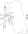
- FIGS. 1A and 1B are illustrations of an example UAV 100 perching on a structure 50 (for example, a pipe), with the UAV 100 having a releasable crawler 130 for inspecting or maintaining the structure 50, according to an embodiment.
- the crawler 130 is shown attached to the UAV 100 in FIG. 1A and not attached to the UAV 100 (e.g., crawling on the structure 50) in FIG. 1B .
- the structure 50 is larger (such as significantly larger) than the UAV 100.
- the structure 50 is larger in every dimension than the UAV 100, or the structure 50 presents a larger footprint on which to land than the footprint of the UAV 100.
- the structure 50 (or any structure described herein) is a pipe, such as an 203,2 mm (8 inch) or larger diameter pipe.
- FIGS. 1A and 1B show the mother-child configuration in action.
- FIG. 1A shows the UAV 100 after landing on the pipe 50 with the crawler 130 still docked in it.
- FIG. 1B shows the crawler 130 after being released from the UAV 100 to perform the inspection job.
- the crawling capability provided by the releasable crawler 130 gives the UAV 100 important features for inspection and maintenance jobs, such as easier accessibility (e.g., landing does not have to be on the exact spot where inspection or maintenance takes place).
- the crawling further provides for circumferential and longitudinal scans. For instance, in the oil and gas industry, it is important to perform full scans of the pipe 50 to find the minimum steel thickness on a certain area of the pipe 50. Such scans often include circumferential scans and longitudinal scans, for which crawling is well suited.
- the crawling further provides for power efficiency during multiple inspections (e.g., crawling between multiple inspection sites on the same pipe is more power efficient than flying).
- the UAV 100 utilizes four articulated magnets 120 (such as permanent magnets or switchable permanent magnets). To accommodate the landing of the UAV 100 on the pipe 50, each of the magnets 120 (or more precisely, its magnetic field) articulates with a perpendicular orientation with respect to the pipe 50 when the UAV 100 has landed or is perching on the pipe 50.
- each of the magnets 120 (or more precisely, its magnetic field) articulates with a perpendicular orientation with respect to the pipe 50 when the UAV 100 has landed or is perching on the pipe 50.
- the magnetic fields of the articulated magnets 120 are actively switchable on and off (e.g., to allow for easy detachment after job completion).
- a laser scanner 110 e.g., light detection and ranging, or LIDAR
- LIDAR light detection and ranging
- the miniature crawler 130 is connected by a wire (e.g., for power and communication) and includes a UT sensor, four magnetic wheels 140, and two motors to drive the wheels 140 in corresponding pairs (e.g., front and rear).
- the wire also allows the rest of the electronics and batteries for carrying out the inspection or maintenance to be located in the main UAV body 100. This reduces the size, weight, and complexity of the crawler 130.
- the crawler 130 includes a different number of wheels 140 (e.g., two or three wheels, or more than four) and their type (e.g., omniwheels, mecanum wheels, to name a few).
- the magnetic crawler 130 has to contend with various curvatures and various directions (as illustrated throughout) of pipe inspection or maintenance.
- the magnetic crawler 130 has special locomotion systems to navigate pipe curvatures (or similar curvatures from other curved structures or vessels).
- communication between the crawler 130 and the UAV 100 is wired.
- the crawler 130 can be connected to the UAV 100 for power and communication. This can eliminate, for example, the need to host a battery and other electronics inside the crawler 130, making it smaller and saving total weight by utilizing some of the components already existing in the UAV 100.
- communication between the crawler 130 and the UAV 100 is wireless.
- the crawler 130 includes its own battery and electronics, to provide for a more standalone vehicle. This can be useful, for example, when the UAV 100 picks up the crawler 130 from the ground and deploys it on the pipe 50, at which point the UAV 100 can fly to do some other inspection jobs and then go back to pick the crawler 130 up. This can also be useful for numerous crawlers 130 (e.g., a swarm of crawlers 130) to inspect multiple assets, with the UAV 100 working on picking them up one-by-one or in batches from the ground towards their destination and retrieving them upon job completion.
- the wireless connection can be between the crawler(s) 130 and either the UAV 100 or an operator's control station, or both the UAV 100 and the operator's control station.
- the UAV 100 includes a body constructed to enable the UAV 100 to fly (e.g., having rotors, control and guidance devices, and the like).
- the UAV 100 also includes three or more legs connected to the body and configured to land and perch the flying UAV 100 on a curved ferromagnetic surface 50.
- Each leg includes a top (or main) portion connected to the body, and a bottom portion that includes a permanent magnet 120. The bottom portion is configured to magnetically attach the leg to the ferromagnetic surface 50 during the landing and to maintain the magnetic attachment of the leg to the ferromagnetic surface during the perching.
- a passive articulation joint connects the top and bottom portions of the leg, and passively articulates (e.g., pivots) the bottom portion with respect to the top portion in response to the bottom portion approaching the ferromagnetic surface 50 during the landing.
- the UAV 100 further includes a releasable crawler 130 having magnetic wheels 140. The magnetic wheels 140 allow the crawler 130 to detach from the UAV 100 during the perching, and to maneuver the crawler 130 on the ferromagnetic surface 50 while magnetically attaching the crawler 130 to the ferromagnetic surface 50 after the detaching.
- different landing mechanisms of the UAV 100 can be used. These can include different types of adhesion mechanisms such as magnetic or non-magnetic. Examples of magnetic landing mechanisms include magnets that can be shut-off or overcome by a mechanical means during takeoff from the pipe 50. Such magnets include switchable permanent magnets, permanent magnets with an actuated leverage to aid in detachment during takeoff, electro-permanent magnets, and electromagnets. It should be noted, however, that continuous power consumption can be a disadvantage for electromagnets. Non-magnetic adhesion mechanisms can be used for non-ferromagnetic surfaces such as stainless steel, composite pipes, and concrete walls. Such mechanisms include micro-spines, dry gecko-inspired adhesives (e.g., synthetic setae), suction cups, grippers, and claws.
- magnetic landing mechanisms include magnets that can be shut-off or overcome by a mechanical means during takeoff from the pipe 50. Such magnets include switchable permanent magnets, permanent magnets with an actuated leverage to aid in detachment during take
- Inspection payloads and designs include a range of different types of sensors that are often used in the oil and gas industry to inspect pipes and structures.
- a UT sensor is used for thickness measurement.
- a UT sensor for thickness measurement is used throughout at times to represent an example device and application for inspection and maintenance.
- other embodiments are not limited to such a device or application.
- other inspection sensors or probes can be used instead of or in addition to the UT sensor depending on the job, including (but not limited to) eddy current sensors and alternating current field measurement (ACFM) sensors.
- ACFM alternating current field measurement
- the crawler 130 is configured with one or more tools and used for maintenance purposes.
- the crawler 130 can be used to perform light maintenance jobs such as cleaning, surface preparation, and coating repairs.
- the crawler 130 is configured with one or more cameras and used for visual inspection.
- a camera is used for simple visual inspection jobs, such as where only videos or photos of areas of interest need to be obtained, but for which the areas are difficult to inspect directly by the UAV 100.
- the crawler 130 is configured to leave markers (such as paint or QR codes) behind on areas of interest (such as locations where the sensor readings are outside of normal levels, or where faults are detected). These locations, for example, can be where critical thickness levels are detected.
- markers such as paint or QR codes
- areas of interest such as locations where the sensor readings are outside of normal levels, or where faults are detected. These locations, for example, can be where critical thickness levels are detected.
- the UAV 100 scans these markers and creates a 3D reconstruction of the environment showing the exact location of these markers.
- the UAV 100 uses an on-board RGB-D camera to detect the markers and compute their locations with respect to the UAV 100. Using the UAV's GPS position, absolute locations of the markers can be computed or otherwise determined. It should be noted that while the UAV 100 is scanning the markers, the crawler 130 can, for example, stay on the pipe 50 or be re-docked with the UAV 100.
- the crawler 130 uses wireless localization to identify problem locations on the asset, such as with virtual markers. In other words, the locations of faults can be determined even without physical markers, albeit with less precision. This is because the crawler's location with respect to the UAV 100 can be computed (or otherwise determined) using wireless sensors.
- the UAV 100 carries an ultra-wide band (UWB) sensor array that receives wireless signals for another UWB transmitter that is mounted on the crawler 130.
- UWB ultra-wide band
- the crawler's relative location can then be measured regardless of whether the UAV 100 is in flight or attached to the pipe 50.
- the crawler location with respect to the UAV 100 is tagged and captured. With the UAV's GPS sensor, the absolute positions of these faults can be determined. In some embodiments, when GPS is not available, the UAV's location is estimated based on the flight trajectory and IMU data from its home base, where GPS is available.
- previously computed (or determined) inspection locations are transferred from the UAV 100 to an operator computer, or a ground station. Then, the inspection locations are visualized on, for example, a previously-built 3D model of the inspected plant, or a 3D model that can be constructed from the UAV's onboard sensors, e.g., depth camera or 3D LIDAR. In addition, in some such embodiments, the visualized locations are annotated with the corresponding measured thicknesses (or other sensed values or information).
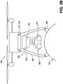
- FIGS. 2A and 2B are exploded and profile views, respectively, of an example UAV 200 or drone configured with an undercarriage 220 having (1) perching legs 280 for perching on a structure 150 (such as a carbon steel pipe or other curved ferromagnetic surface 150) and (2) a crawler 260 for releasing from the perched UAV 200 on the structure 150 to inspect or maintain the structure 150, according to an embodiment.
- the crawler 260 has magnetic wheels 270 for maneuvering on while adhering to the curved ferromagnetic surface 150 (e.g., regardless of orientation with respect to gravity, even upside down).
- a pipe is used throughout as an example structure having a curved ferromagnetic surface.
- the UAV 200 or drone can include rotors (such as four or six rotors) and a control unit for adjusting the rotation speeds of the individual rotors to balance the load of the UAV 200 or cause the UAV 200 to move in a desired direction.
- rotors such as four or six rotors
- control unit for adjusting the rotation speeds of the individual rotors to balance the load of the UAV 200 or cause the UAV 200 to move in a desired direction.
- the UAV 200 includes a set of mounting points 210 for mating with a similar set of mounting points 230 of the undercarriage 220.
- the undercarriage 220 includes a set of perching legs 280 (e.g., four such legs 280), each with an articulated magnet 290.
- the articulated magnets 290 are mounted to the legs 280 so as to permit for orienting towards and adhering to the curved ferromagnetic surface 150 when the UAV 200 approaches and perches on the surface 150.
- the articulation joint enables pivoting, which can be in multiple axes such as when the joint comprises a universal joint, of the magnet 290 in its housing relative to the surface 150 to which the leg 280 is about to perch.
- the pivoting can be around an axis of the leg 280 or joint, as shown, to assume an angle ⁇ relative to the axis, and optionally relative to additional angles ⁇ , etc.
- the UAV 200 and undercarriage 220 are configured primarily to perch and deploy/retrieve the crawler 260 to or from the top (or near the top) of a structure (e.g., to keep the rotors of the UAV 200 reasonably level before, during, and after perching).
- the undercarriage 220 includes a height adjustment mechanism 240 (for example, a motor or other actuator) for lowering the crawler 260 from the perched UAV 200 to the surface 150 or for raising the crawler 260 from the surface 150 to the perched UAV 200.
- a docking mechanism 250 connects the height adjustment mechanism 240 to the crawler 260, such as with a docking port.
- the docking port allows the crawler 260 to disengage (e.g., drive away from) the perched UAV 200 once deployed on the surface 150 or to engage (e.g., drive into or onto) the perched UAV 200 when ready to leave the surface 150, such as to return to a home base or other structure or component to be inspected or maintained.
- the docking mechanism 250 may also allow for information or energy transfer between the UAV 200 and the crawler 260, such as to download instrumentation data from the crawler 260 to the UAV 200 or to recharge a battery of the crawler 260 from the UAV 200.
- the height adjustment mechanism 240 is used to adjust the height of the crawler 260 based on the pipe diameter (e.g., to ensure successful release on the surface 150). For instance, on large pipes (or flat surfaces), the height of the docked crawler 260 to the surface 150 is greater than when on small diameter pipes. As such, for large pipes (or flat surfaces), the crawler 260 is deployed to a lower height to reach the surface 150 whereas on a small diameter pipe, the crawler 260 is deployed and released at a higher point. In addition, is some embodiments, the height adjustment mechanism 240 is used to re-dock the crawler 260 after job completion. This allows the docking mechanism 250 to be at the correct height with respect to the crawler 260. Again, different pipe diameters can have corresponding different heights. In some embodiments, the height adjustment mechanism 240 is used to pull the crawler 260 and break its magnetic attachment to the ferromagnetic surface 150.
- the height adjustment mechanism 240 is actuated, such as with a motor. In some embodiments, the height adjustment mechanism 240 is passive when it is not used to detach the crawler 260. For example, in one such embodiment, the height adjustment mechanism 240 is spring-loaded so that it can always be at maximum possible extension to press against the pipe 150 when the UAV 200 is perched and deploying the crawler 260.
- each leg 280 in the perching mechanism features an articulated magnet 290 (such as a permanent magnet or a switchable permanent magnet).
- the articulation of the leg 280 is passive in that the articulated magnet 290 is designed to articulate about the axes shown in FIG.
- the undercarriage 220 in response to the magnetic attraction of the magnet 290 and the ferromagnetic surface 150 when the UAV 200 (or more precisely, the attached undercarriage 220) is in close proximity to the target ferromagnetic surface 150, such as in response to initial contact between the two.
- the undercarriage 220 can be mounted on any UAV with the suitable mounting points (e.g., to mate with mounting points 230) and payload capacity (e.g., to carry and deploy the undercarriage 220 in flight).
- the crawler 260 after deployment and job completion, the crawler 260 re-docks with the UAV 200, or more specifically, with the docking mechanism 250.
- the process of re-docking and takeoff from the ferromagnetic surface 150 by the UAV 200 with the crawler 260 also involves magnetically detaching the crawler 260 from the surface 150.
- the UAV 200 uses the height adjustment mechanism 240 to pry the crawler 260 away from the magnetic attraction of the magnetic wheels 270 of the crawler 260 and the ferromagnetic surface 150.
- the magnetic wheels 270 use switchable magnets to disable adhesion to the ferromagnetic surface 150 after re-docking.
- the docking mechanism 250 includes a ramp that lies on the pipe 150 and is attached to the UAV 200.
- the crawler 260 climbs the ramp while re-docking (such as parking onto an inclined driveway).
- the crawler's wheel motors are used to force the magnets of the magnetic wheels 270 to detach using the driving torque of the crawler 260.
- the ramp can be made of a metallic material (e.g., steel) or a non-magnetic material, depending on factors such as weight, strength, and the like.
- magnetic attachment of the UAV 200 is achieved to enable the UAV 200 to fly to a next location together with the crawler 260 as a payload securely retained by the UAV 200.
- FIG. 3A is a profile view of an example UAV 300 having modular mounting points 310 for attaching the undercarriage 220 of FIGS. 2A and 2B
- FIGS. 3B and 3C are profile views of the UAV 300 with the attached undercarriage 220 at side and top orientations, respectively, with respect to the UAV 300, according to an embodiment.
- This modular approach allows for mounting the undercarriage 220 (payload) on, for example, the bottom, front, or top of the UAV 300 in order to allow for perching on the top, side, or bottom, respectively, of the pipe 150.
- the UAV 300 together with the undercarriage 220 attached to a suitable set of mounting points 310, can perch on the top, side, or bottom of the pipe 150 using adaptable perching legs 280, as illustrated in FIGS. 3A, 3B , and 3C , respectively.
- each leg 280 is designed with an articulated magnet 290 that breaks the leg 200 into two distinct parts, a main body rigidly mounted to the undercarriage 220 and a moving (or articulating) magnet 290.
- This provides the leg 280 with at least a rotational degree of freedom, which allow the magnets 290 to passively realign their orientation (e.g., perpendicular) toward the pipe 150 during landing for perfect or near perfect adhesion.
- an onboard flight controller for the UAV 300 is configured (e.g., by logic, code, or the like) to keep the UAV 300 in a stable hover regardless of weight distribution. For example, if the UAV 300 becomes forward-heavy, then the controller is configured to sense the slightest tilt and compensate for that by increasing the thrust or rotation speeds (of the rotors) on the heavy side to keep the UAV 300 level and stable. In some embodiments (such as illustrated in FIGS.
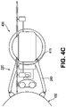
- FIGS. 4A, 4B , and 4C are profile views of an example UAV 400 having rotatable mounting points 410 for attaching the undercarriage 220 of FIGS. 2A through 3C , together with the attached undercarriage 220 at bottom, top, and side orientations, respectively, with respect to the UAV 400, according to an embodiment.
- the UAV 400 includes a motor or actuator for rotating the mounting points 410 to a suitable orientation, including during flight (e.g., dynamic rotation).
- the mounting points 410 can be manually rotated to a desired orientation prior to a mission (e.g., static rotation).
- the motorized system e.g., motorized mounting points 410 and motor to rotate the mounting points 410 circumferentially about the UAV 400
- the UAV 400 automatically changes the orientation of the undercarriage 220 (e.g., during flight) depending on factors such as the observed or otherwise known obstacles around the pipe 150.
- FIGS. 4A, 4B , and 4C illustrate how the motorized system changes orientation of the perching legs 280 to land on top, bottom, or side, respectively, of the pipe 150.
- the UAV has a controller configured (such as by computer code) to plan which is the safest spot on the pipe 150 on which to perch, such as top, side, or bottom of the pipe 150, or somewhere in between.
- the rotation is achieved through a circular rail around the UAV's body 400.
- heavy components such as batteries can be placed on the rail (e.g., at opposing positions to the mounting points 410) to serve as counter weights.
- the rotation of the undercarriage 220 is manually adjusted by the user instead of being motorized. For instance, this can be done to save weight, complexity, power, or the like.
- An example technique for accomplishing this manual adjustment is by releasing hand screws to unlock manual rotation of undercarriage 220 about the circular rail, which can then be relocked once the undercarriage 220 is in the desired position.
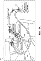
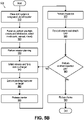
- FIGS. 5A and 5B are an illustration and corresponding flow chart, respectively, of an example inspection method 500 of a target structure 555 (e.g., pipe) using a perching UAV 505 with a releasable crawler 535, according to an embodiment.
- FIG. 5A illustrates the method 500 pictorially, with illustrated steps 1 through 9 that correspond to steps 510 through 590, respectively, of the flow chart of FIG. 5B .
- the method 500 will be described with reference to steps 510 through 590 of FIG. 5B , but can also be visualized with corresponding reference to FIG. 5A at any point.
- FIGS. 5A and 5B describe an inspection method 500 to inspect assets, such as those in the oil and gas industry including pipes, tanks, and other structures, using a perching UAV 505 with releasable crawler 535 system as described in example embodiments throughout.
- the system includes the UAV 505 that is used to carry the releasable crawler 535 to be deployed on elevated structures such as steel pipes (e.g., pipe 555) in order to perform, for example, contact inspection jobs.
- elevated structures such as steel pipes (e.g., pipe 555)
- the method 500 systematically and safely performs the inspection job.
- the method 500 can be programmed or encoded in, for example, system software in order to automate the process 500 as much as possible.
- the method 500 illustrates a multi-step mission to enable a successful and safe inspection of the target pipe 555.
- FIG. 5A depicts the method steps in an example sequential order. Some of the key steps including flying the UAV 505 either autonomously or manually to the vicinity of the inspection target 555 (referred to as a pre-perching waypoint). Once the target 555 is close enough and detectable by the sensors of the UAV 505, such as a depth camera or laser scanner (LIDAR), the operator initiates an autonomous landing onto the target 555 by either confirming the auto-detected target 555 or selecting a different target on the screen.
- the UAV 505 is programmed (or otherwise configured) to autonomously perform a perching maneuver (e.g., land on the target 555) so that it can safely approach the target 555 and attach itself to the target 555 autonomously.
- a perching maneuver e.g., land on the target 555
- a crawler 535 is released from the UAV 505.
- the crawler 535 is driven manually by the operator on the target surface 555 to perform the inspection job.
- the crawler 535 is programmed or otherwise configured to maneuver on the pipe 555 and perform the inspection (or maintenance) job autonomously.
- the crawler 535 is re-docked (e.g., by operator, or autonomously using pre-programmed code or logic) into the UAV 505, which is then flown to another inspection area or back home to the takeoff and landing location 515.
- the method 500 begins with the pre-flight stage, such as the step of placing 510 the UAV system 505 (or drone) in a designated takeoff (and landing) location 515.
- the pre-flight stage such as the step of placing 510 the UAV system 505 (or drone) in a designated takeoff (and landing) location 515.
- an operator places the UAV 505 in the designated takeoff location 515 with the rotors (or propellers) removed.
- the method 500 includes the step of powering on 520 the UAV 505 and performing preflight checks and initialization.
- an operator performs the checks and initialization. The mission should not proceed if any of the checks fails.
- the checks can include, but are not limited to: checking the battery health of the UAV 505, checking that the propulsion system works as expected, checking communications between the operator's control station and the UAV/crawler 505/535, checking the perching mechanism functionality, checking the functionality of the crawler 535 and its docking mechanism, checking and calibrating the inspection tools (e.g., UT sensor), installing the rotors or propellers on the UAV 505, setting the UAV 505 in position mode (e.g., in order to stabilize its position in the air), enabling obstacle avoidance mode (e.g., in order to enable the UAV 505 to navigate the environment safely during its autonomous mission through the waypoints), and selecting the flight guidance mode of the UAV 505 (e.g., to manual, autonomous, or mixed mode, where some waypoints are navigated autonomously and some waypoints are navigated manually).
- the inspection tools e.g., UT sensor
- the method 500 further includes the step of performing mission planning 530, which differs depending on factors such as the type of flight guidance mode.
- autonomous guidance mode is selected (where the UAV 505 is programmed to fly autonomously to the different waypoints).
- the operator defines waypoints and the associated actions (e.g., a takeoff waypoint at predefined altitude, a pre-perching waypoint at a predefined distance from the target 555, and failsafe waypoints in case unplanned events take place).
- the mission planner provides estimates on the expected mission times. For example, this can be based on the estimated power consumption given the input mission plan by the operator (e.g., estimated time of flight to and from the target 555, estimated maximum time of the inspection operation, and the like).
- manual guidance mode is selected.
- the operator plans a mission by visually identifying the best and safest path to fly from the take-off point 515 towards the vicinity of the inspection target 555.
- the mission planner plans expected mission times to have enough battery life for a return to home 515.
- the mission planner can set geofence limits that should not be exceeded during manual operation.
- mixed guidance mode is selected. This is similar to autonomous mode (where a mission is fully planned on the control station) but differs by allowing the operator to select some of the waypoints to be navigated manually (e.g., in case obstacles or a difficult environment lies ahead of the UAV 505 on the way to that waypoint). This is useful, for example, when the operator's confidence in automated flight is not high enough for a particular waypoint.
- the method 500 further includes the step of initiating the flight mission and flying 540 the UAV 505 to the vicinity of the inspection target 555.
- this includes commanding the UAV 505 to go to the takeoff waypoint, and commanding the UAV 505 to go to the pre-perching waypoint (e.g., in the vicinity of the inspection target 555).
- the UAV 505 is configured (e.g., programmed) to automatically transition from one mission waypoint to the next, while in another embodiment, the UAV 505 is configured to wait for operator confirmation each time it arrives at a waypoint before proceeding to the next.
- this includes manually flying the UAV 505 to the vicinity of the inspection target 555 in preparation for perching.
- the step of initiating and flying 540 is similar to the autonomous mode, but the operator is alerted by the system to take over when the manual portions of the mission start.
- the method 500 further includes the step of executing the perching 550 maneuvers.
- This includes defining the target of interest (e.g., using the operator's control station), with target detection and localization software configured (e.g., programmed) to use the defined target 555 to detect and localize the target 555 in order to plan for perching.
- the operator confirms object detection and issues the perching command.
- the UAV 505 is programmed to autonomously perform the perching in two steps.
- a first step the UAV 505 autonomously approaches the target 555 at a pre-touchdown position where, in one embodiment, the operator confirms its accurate position before final touchdown, and (2) autonomously performs a final alignment using an onboard sensor (e.g., 2D LIDAR) that, in one embodiment, is also confirmed by the operator.
- an onboard sensor e.g., 2D LIDAR
- the UAV 505 is commanded to fall back to a failsafe waypoint (e.g., where perching can be re-executed), or a mission abort is safely commanded (to which the UAV 505 is configured to return home).
- the UAV 505 waits for the pre-touchdown to be confirmed, at which point the UAV 505 is programmed to touch down autonomously while the perching mechanism is configured to provide a confirmation of perching completion. If confirmation of perching completion is not indicated, the UAV 505 goes to a failsafe waypoint, where perching can be re-executed, or a mission abort is commanded (and the UAV 505 returns home).
- the method 500 further includes the step of releasing 560 the crawler 535.
- the operator commands crawler release. Once the crawler 535 is deployed on the target 555, and a confirmation is indicated by the system, the operator starts the inspection step.
- the method 500 further includes the step of inspecting 570 the target 555.
- the operator controls the crawler 535 to perform the inspection job on the target 555.
- the crawler 535 is operated via a cable that is connected to the UAV 505.
- the crawler 535 is operated through a wireless connection, and the crawler motion is constrained within a predefined safe region of communication.
- the UAV system 505 is programmed or otherwise configured to monitor the overall status and provide estimates on the maximum allowed inspection time depending on, for example, the available power.
- the UAV system 505 is further programmed to store inspection data (e.g., from the UAV 505, or from the crawler 535, or from the UAV 505 as obtained by the crawler 535) continuously on the system memory, and to transfer the stored inspection data to the operator control and monitoring station in real time.
- the method 500 further includes the step of crawler re-docking 580 and UAV detachment.
- the crawler 535 is driven back to the UAV 505 by the operator and an autonomous re-docking command is issued.
- the crawler 535 can be programmed or otherwise configured to perform an autonomous re-docking with the UAV 505.
- the UAV 505 transitions to the detachment state (e.g., detaches from the magnetic attraction of the target 555).
- the operator commands the UAV 505 to go to the hover state, and the latching mechanism is disengaged.
- the operator commands the UAV 505 to go to a predefined failsafe waypoint in the vicinity of the target 555.
- the method 500 further includes the step of deciding 585 whether to safely return the UAV 505 back to the takeoff and landing position 515, or to command the UAV 505 (with attached and re-docked crawler 535) to go to another inspection job target.
- the method 500 further includes the step of flying 590 the UAV 505 back home (e.g., to the takeoff and landing position 515).
- the UAV 505 goes to the landing position 515 at a predefined landing altitude after which it descends vertically to the ground. Once landing is confirmed, the rotors or propellers are disarmed, and the mission ends.
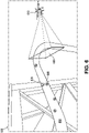
- FIG. 6 is an illustration of an example releasable crawler 620 visibly marking interesting (e.g., suspect) portions 640 of a structure (e.g., pipe 650) encountered during inspection or maintenance of the structure 650, together with an example UAV 610 detecting the visible markers 640 left by the crawler 620, according to an embodiment.
- the crawler 620 has marked numerous inspection points 640 (e.g., where sensor measurements were out of normal bounds) for identification by the UAV 610 (e.g., through camera view 630 as sensed by the UAV 610).
- the crawler 620 can be programmed to leave physical markers 640 (such as paint or QR codes) at inspected locations of the pipe 650 where faults (e.g., thickness levels below a critical threshold) are detected.
- the UAV 610 is programmed to use an on-board RGB-D camera (with view 630) to detect the markers 640 and compute (or otherwise determine) their locations with respect to the UAV 610. Using the UAV's GPS position, the UAV 610 is further programmed to compute (or otherwise determine) absolute locations of the markers 640 from these detections.
- the crawler 620 stays on the pipe 650.
- the crawler 620 is docked into the UAV 610 while the UAV 610 scans the markers 640.
- FIGS. 7A and 7B are illustrations of example techniques for a releasable crawler 620 to virtually mark interesting (e.g., suspect) portions of a structure (e.g., pipe 650) encountered during inspection or maintenance of the structure 650, together with a UAV 610 for performing wireless localization using the virtual markers, according to an embodiment.
- the UAV 610 is perched on the pipe 650
- the UAV 610 is hovering near the pipe 650, such as at a pre-perching waypoint.
- the location of faults can be determined using virtual markers (e.g., without using physical markers), albeit with a possible loss of precision.
- the UAV 610 is programmed (or otherwise configured) to compute the crawler location with respect to the UAV 610 using wireless sensors. More specifically, in one embodiment, the UAV 610 carries an ultra-wide band (UWB) sensor array that receives wireless signals broadcast from an UWB transmitter that is mounted on the crawler 620. The crawler's relative location is measured regardless if the UAV 610 is in flight (e.g., FIG. 7B ) or attached to the pipe 650 (e.g., FIG. 7A ).
- UWB ultra-wide band
- the UAV 610 is programmed (or otherwise configured) so that whenever a fault is detected by the crawler 620 while crawling (e.g., maneuvering and inspecting on the pipe 650), the crawler's location with respect to the UAV 610 is tagged and captured. Together with the UAV's GPS sensor, the UAV 610 is further programmed to find (e.g., compute, determine) the absolute positions of these faults. In an embodiment, for situations where GPS is not available, the UAV 610 is programmed (or otherwise configured) to estimate the UAV's location based on sensor or other instrumentation data such as flight trajectory and IMU data from its home base (e.g., where GPS is available).
- FIG. 8 is an example structure 800 for deploying a UAV with a releasable crawler to inspect or maintain the structure, according to an embodiment.
- the UAV has deployed the crawler to perform thickness determinations (e.g., using a UT sensor).
- the crawler has marked two example locations 810 and 820.
- Location 810 corresponds to a section of the pipe whose thickness has reached a critically low value, in this case 2 millimeters (mm).
- location 820 corresponds to a section of the pipe whose thickness is normal, in this case 5 mm.
- these inspection points 810 and 820 are part of a mapping and annotation of the structure 800.
- the UAV and crawler are programmed (or otherwise configured) to perform some or all of this mapping and annotation.
- previously computed inspection locations are transferred from the UAV to an operator computer, or a ground station.
- a computing system is programmed (or otherwise configured) to visualize the inspection locations (e.g., 810 and 820) on a previously built 3D model of the inspected plant 800.
- the UAV is programmed (or otherwise configured) to construct a 3D model of portions of the plant 800 using data obtained by the UAV's onboard sensors, e.g., depth camera or 3D LIDAR.
- the UAV is further programmed to annotate the visualized locations with the corresponding measured thicknesses obtained by the crawler when inspecting the structure 800.
- FIG. 9 is a flow chart of an example method 900 of inspecting or maintaining a structure (such as a pipe, as in pipe 50, 150, 555, or 650) having a curved ferromagnetic surface using a UAV (such as UAV 100, 200, 300, 400, 505, or 610) with a releasable crawler (such as releasable crawler 130, 260, 535, or 620), according to an embodiment.
- a structure such as a pipe, as in pipe 50, 150, 555, or 650
- UAV such as UAV 100, 200, 300, 400, 505, or 610
- a releasable crawler such as releasable crawler 130, 260, 535, or 620
- Some or all of the method 900 can be performed using components and techniques illustrated in FIGS. 1A through 8 . Portions of this and other methods disclosed herein can be performed on or using a custom or preprogrammed logic device, circuit, or processor, such as a programmable logic circuit (PLC), computer, software, or other circuit (e.g., ASIC, FPGA) configured by code or logic to carry out their assigned task.
- PLC programmable logic circuit
- the device, circuit, or processor can be, for example, a dedicated or shared hardware device (such as a laptop, a workstation, a tablet, a smartphone, part of a server, or a dedicated hardware circuit, as in an FPGA or ASIC, or the like), or computer server, or a portion of a server or computer system.
- the device, circuit, or processor can include a non-transitory computer readable medium (CRM, such as read-only memory (ROM), flash drive, or disk drive) storing instructions that, when executed on one or more processors, cause portions of the method 900 (or other disclosed method) to be carried out.
- CRM computer readable medium
- ROM read-only memory
- flash drive or disk drive
- instructions that, when executed on one or more processors, cause portions of the method 900 (or other disclosed method) to be carried out.
- the order of the operations can be varied, and that some of the operations can be omitted.
- Some or all of the method 900 can also be performed using logic, circuits, or processors located on a UAV configured to carry out the method 900.
- processing begins with the step of flying 910 the UAV to a proximity of the ferromagnetic surface, followed by the step of perching 920 the UAV on the ferromagnetic surface.
- the perching 920 includes passively articulating legs (such as perching legs 280) of the UAV toward the curvature of the ferromagnetic surface using corresponding magnets (such as articulated magnets 120 or 290) in the legs while approaching the ferromagnetic surface.
- the perching 920 also includes magnetically attaching the articulated legs of the UAV to the ferromagnetic surface using the corresponding magnets.
- the method 900 further includes the step of maintaining 930 the magnetic attachment of the legs to the ferromagnetic surface throughout the perching, and the step of detaching 940 the crawler onto the ferromagnetic surface from the perched UAV.
- the method 900 further includes the step of maneuvering 950 the detached crawler on the ferromagnetic surface while magnetically attaching the crawler to the ferromagnetic surface using magnetic wheels (such as magnetic wheels 140 or 270) of the crawler.
- the method 900 includes inspecting or maintaining the ferromagnetic surface during the maneuvering using a probe or tool (such as a UT sensor) of the crawler. In still further embodiments, the method 900 includes breaking the magnetic attachment of the crawler from the ferromagnetic surface and re-docking the detached crawler with the perched UAV after the maneuvering.
- the methods described herein may be performed in part or in full by software or firmware in machine readable form on a tangible (e.g., non-transitory) storage medium.
- the software or firmware may be in the form of a computer program including computer program code adapted to perform some or all of the steps of any of the methods described herein when the program is run on a computer or suitable hardware device (e.g., FPGA), and where the computer program may be embodied on a computer readable medium.
- tangible storage media include computer storage devices having computer-readable media such as disks, thumb drives, flash memory, and the like, and do not include propagated signals. Propagated signals may be present in a tangible storage media, but propagated signals by themselves are not examples of tangible storage media.
- the software can be suitable for execution on a parallel processor or a serial processor such that the method steps may be carried out in any suitable order, or simultaneously.
Landscapes
- Engineering & Computer Science (AREA)
- Physics & Mathematics (AREA)
- General Physics & Mathematics (AREA)
- Mechanical Engineering (AREA)
- Aviation & Aerospace Engineering (AREA)
- Chemical & Material Sciences (AREA)
- Remote Sensing (AREA)
- Radar, Positioning & Navigation (AREA)
- Combustion & Propulsion (AREA)
- Transportation (AREA)
- Health & Medical Sciences (AREA)
- General Health & Medical Sciences (AREA)
- Immunology (AREA)
- Pathology (AREA)
- Biochemistry (AREA)
- Analytical Chemistry (AREA)
- Life Sciences & Earth Sciences (AREA)
- Theoretical Computer Science (AREA)
- Multimedia (AREA)
- Computer Networks & Wireless Communication (AREA)
- Electromagnetism (AREA)
- Computer Vision & Pattern Recognition (AREA)
- Automation & Control Theory (AREA)
- Acoustics & Sound (AREA)
- Astronomy & Astrophysics (AREA)
- Signal Processing (AREA)
- Business, Economics & Management (AREA)
- Artificial Intelligence (AREA)
- Evolutionary Computation (AREA)
- Game Theory and Decision Science (AREA)
- Medical Informatics (AREA)
- General Engineering & Computer Science (AREA)
- Manipulator (AREA)
- Length Measuring Devices By Optical Means (AREA)
- Investigating Or Analyzing Materials By The Use Of Ultrasonic Waves (AREA)
- Control Of Position, Course, Altitude, Or Attitude Of Moving Bodies (AREA)
- Working Measures On Existing Buildindgs (AREA)
- Magnetic Bearings And Hydrostatic Bearings (AREA)
- Investigating Or Analyzing Materials By The Use Of Magnetic Means (AREA)
- Traffic Control Systems (AREA)
Applications Claiming Priority (3)
| Application Number | Priority Date | Filing Date | Title |
|---|---|---|---|
| US201862772700P | 2018-11-29 | 2018-11-29 | |
| US16/694,092 US11584458B2 (en) | 2018-11-29 | 2019-11-25 | Inspection method using a perching UAV with a releasable crawler |
| PCT/US2019/063400 WO2020154035A1 (en) | 2018-11-29 | 2019-11-26 | Inspection method using a perching uav with a releasable crawler |
Publications (2)
| Publication Number | Publication Date |
|---|---|
| EP3887252A1 EP3887252A1 (en) | 2021-10-06 |
| EP3887252B1 true EP3887252B1 (en) | 2022-12-28 |
Family
ID=70848632
Family Applications (5)
| Application Number | Title | Priority Date | Filing Date |
|---|---|---|---|
| EP19888236.7A Active EP3887252B1 (en) | 2018-11-29 | 2019-11-26 | Inspection method using a perching uav with a releasable crawler |
| EP19827927.5A Withdrawn EP3887250A1 (en) | 2018-11-29 | 2019-11-26 | Articulated magnet-bearing legs for uav landing on curved surfaces |
| EP19824094.7A Withdrawn EP3887251A1 (en) | 2018-11-29 | 2019-11-26 | Perching uav with releasable crawler |
| EP19827933.3A Withdrawn EP3887235A1 (en) | 2018-11-29 | 2019-11-26 | Crawler vehicle with automatic probe normalization |
| EP19827944.0A Active EP3887859B1 (en) | 2018-11-29 | 2019-11-27 | Automation methods for uav perching on pipes |
Family Applications After (4)
| Application Number | Title | Priority Date | Filing Date |
|---|---|---|---|
| EP19827927.5A Withdrawn EP3887250A1 (en) | 2018-11-29 | 2019-11-26 | Articulated magnet-bearing legs for uav landing on curved surfaces |
| EP19824094.7A Withdrawn EP3887251A1 (en) | 2018-11-29 | 2019-11-26 | Perching uav with releasable crawler |
| EP19827933.3A Withdrawn EP3887235A1 (en) | 2018-11-29 | 2019-11-26 | Crawler vehicle with automatic probe normalization |
| EP19827944.0A Active EP3887859B1 (en) | 2018-11-29 | 2019-11-27 | Automation methods for uav perching on pipes |
Country Status (8)
| Country | Link |
|---|---|
| US (5) | US11097796B2 (zh) |
| EP (5) | EP3887252B1 (zh) |
| JP (5) | JP7475347B2 (zh) |
| KR (5) | KR20210110301A (zh) |
| CN (5) | CN113453981A (zh) |
| SA (3) | SA521422005B1 (zh) |
| SG (5) | SG11202105481PA (zh) |
| WO (5) | WO2020112859A1 (zh) |
Families Citing this family (46)
| Publication number | Priority date | Publication date | Assignee | Title |
|---|---|---|---|---|
| US10078136B2 (en) * | 2014-03-25 | 2018-09-18 | Amazon Technologies, Inc. | Sense and avoid for automated mobile vehicles |
| US11926172B2 (en) * | 2018-03-30 | 2024-03-12 | Jabil Inc. | Apparatus, system, and method of providing a stabilizing drive system for a robotic vehicle |
| US11338911B2 (en) * | 2018-09-18 | 2022-05-24 | Insitu, Inc. | Magnetic recovery systems and magnetic docking mechanisms for fixed-wing unmanned aerial vehicles |
| US11097796B2 (en) * | 2018-11-29 | 2021-08-24 | Saudi Arabian Oil Company | Articulated magnet-bearing legs for UAV landing on curved surfaces |
| US11385204B2 (en) * | 2018-12-11 | 2022-07-12 | The Boeing Company | Fan-propelled surface-adhering apparatus for automated maintenance operations |
| WO2021014396A1 (en) * | 2019-07-24 | 2021-01-28 | Detect Technologies Private Limited | An arm mechanism for docking an unmanned aerial vehicle to a structure for non-destructive testing |
| WO2021038301A1 (en) * | 2019-08-23 | 2021-03-04 | Peter Kessler | Pipe inspection device with variable height control |
| KR102323975B1 (ko) * | 2020-05-07 | 2021-11-09 | 손영선 | 빠르고 오랜 시간 비행 하는 드론 |
| KR102383936B1 (ko) * | 2020-07-31 | 2022-05-06 | 주식회사 시에라베이스 | 목표드론 무력화장치 |
| KR20230023797A (ko) * | 2020-07-31 | 2023-02-17 | 제이에프이 스틸 가부시키가이샤 | 검사 장치, 검사 시스템 및 검사 방법, 그리고 부재의 보수 방법 |
| CN111679693B (zh) * | 2020-08-17 | 2020-12-04 | 国网湖北省电力有限公司检修公司 | 一种基于磁场强度检测的无人机避障方法 |
| US11782456B2 (en) * | 2020-09-01 | 2023-10-10 | Indoor Robotics Ltd. | Device, system and a method for magnetically docking a flying apparatus |
| CN112034890B (zh) * | 2020-09-15 | 2021-09-24 | 西安爱生无人机技术有限公司 | 无人机人机协同控制系统 |
| CN112130457A (zh) * | 2020-09-21 | 2020-12-25 | 南京航空航天大学 | 一种变体无人机栖落机动的模糊飞行控制方法 |
| CN112305071B (zh) * | 2020-10-23 | 2022-07-12 | 齐鲁工业大学 | 一种基于麦克纳姆轮的导波检测管外机器人及其工作方法 |
| CN112317459B (zh) * | 2020-10-29 | 2021-11-02 | 广西壮族自治区特种设备检验研究院 | 一种用于容器表面清洗打磨装备系统 |
| US11650185B2 (en) | 2020-11-30 | 2023-05-16 | Saudi Arabian Oil Company | System and method for passive normalization of a probe |
| US11584516B2 (en) * | 2020-11-30 | 2023-02-21 | Saudi Arabian Oil Company | Bi-stable and switchable magnetic legs for UAV landing on curved surfaces |
| US11584525B2 (en) * | 2020-11-30 | 2023-02-21 | Saudi Arabian Oil Company | Deep learning-based localization of UAVs with respect to nearby pipes |
| US11760127B2 (en) | 2020-12-03 | 2023-09-19 | Saudi Arabian Oil Company | Two-wheel compact inspection crawler with automatic probe normalization |
| US11679875B2 (en) * | 2020-12-03 | 2023-06-20 | Saudi Arabian Oil Company | Mechanism for docking a magnetic crawler into a UAV |
| KR102417964B1 (ko) * | 2021-01-21 | 2022-07-06 | 부산대학교 산학협력단 | 드론의 험지 착륙을 위한 4족 랜딩 시스템 및 그의 동작 방법 |
| US11225325B1 (en) * | 2021-03-12 | 2022-01-18 | DroneUp, LLC | Payload delivery and drop device for unmanned aerial vehicle for automatic release upon surface contact |
| US11865698B2 (en) | 2021-04-20 | 2024-01-09 | Gecko Robotics, Inc. | Inspection robot with removeable interface plates and method for configuring payload interfaces |
| EP4327047A1 (en) | 2021-04-22 | 2024-02-28 | Gecko Robotics, Inc. | Systems, methods, and apparatus for ultra-sonic inspection of a surface |
| CN113212135A (zh) * | 2021-05-19 | 2021-08-06 | 哈尔滨工业大学 | 一种带有自定位功能的全向移动机器人模块化底盘 |
| CN215098250U (zh) * | 2021-05-27 | 2021-12-10 | 上海峰飞航空科技有限公司 | 一种垂直起降无人机 |
| KR20230016487A (ko) * | 2021-07-26 | 2023-02-02 | 현대자동차주식회사 | 장애물 형상 추정 장치 및 그 방법 |
| US11878796B2 (en) * | 2021-07-30 | 2024-01-23 | Saudi Arabian Oil Company | Perching UAV with releasable crawler |
| US11885769B2 (en) | 2021-08-18 | 2024-01-30 | Saudi Arabian Oil Company | UAV for continuous ultrasound testing (UT) scans |
| KR102589941B1 (ko) * | 2021-08-24 | 2023-10-13 | 한국항공우주연구원 | 재사용 발사체 착륙장치 |
| CN113602486B (zh) * | 2021-08-27 | 2023-03-10 | 中国商用飞机有限责任公司 | 小车式起落架及飞行器 |
| US20230079054A1 (en) * | 2021-09-10 | 2023-03-16 | Exploration Robotics Technologies Inc. | System and method for autonomous inspection for asset maintenance and management |
| US20230110540A1 (en) * | 2021-10-08 | 2023-04-13 | Saudi Arabian Oil Company | System and method for position tracking of a crawler on a structure |
| CN113985438B (zh) * | 2021-11-12 | 2022-08-12 | 河北农业大学 | 一种植物三维模型重建系统及方法 |
| CN113978761B (zh) * | 2021-11-17 | 2023-04-21 | 中国民用航空飞行学院 | 一种飞机机身检测机器人 |
| CN114212265B (zh) * | 2021-12-31 | 2022-07-01 | 蜂巢航宇科技(北京)有限公司 | 一种多旋翼无人机机库 |
| WO2023159180A1 (en) * | 2022-02-17 | 2023-08-24 | Nutech Ventures | Single-pass 3d reconstruction of internal surface of pipelines using depth camera array |
| US11807407B2 (en) | 2022-03-16 | 2023-11-07 | Saudi Arabian Oil Company | System, apparatus, and method for inspecting industrial structures using a UAV |
| KR102473938B1 (ko) * | 2022-05-09 | 2022-12-06 | 남상균 | 비행 안정성이 향상된 드론 |
| KR102473944B1 (ko) * | 2022-05-09 | 2022-12-06 | 에이에프아이 주식회사 | 기체 안전성이 향상된 드론 |
| CN114910026B (zh) * | 2022-06-15 | 2023-08-22 | 南京工程学院 | 一种用于球墨铸管壁厚检测的三轮自适应小车 |
| KR102514703B1 (ko) * | 2022-07-29 | 2023-03-29 | (주)한맥기술 | 복수 개의 카메라를 이용하여 구조물의 손상 영역을 촬영하는 무인 비행 장치 및 이를 이용한 구조물 손상 검사 장치 |
| KR102562370B1 (ko) * | 2022-11-01 | 2023-08-01 | 주식회사 자연과기술 | 항공 라이다를 이용한 평탄도 및 고도 측정 시스템 |
| CN115575488B (zh) * | 2022-11-21 | 2023-06-02 | 中国石油大学(华东) | 基于acfm与视觉的集成探头及协同检测方法 |
| CN117554488B (zh) * | 2024-01-11 | 2024-03-22 | 成都工业学院 | 一种超声干耦合的罐体缺陷智能检测小车 |
Family Cites Families (113)
| Publication number | Priority date | Publication date | Assignee | Title |
|---|---|---|---|---|
| JPS5350221Y2 (zh) * | 1973-03-12 | 1978-12-01 | ||
| JPS63149557A (ja) | 1986-12-12 | 1988-06-22 | Hitachi Ltd | 管検査用の無軌道式走査装置 |
| SU1602193A1 (ru) | 1987-12-10 | 1994-04-30 | Мгту Им.Н.Э.Баумана | Автоматическое сканирующее устройство для ультразвукового контроля сварных швов изделий |
| US5220869A (en) * | 1991-08-07 | 1993-06-22 | Osaka Gas Company, Ltd. | Vehicle adapted to freely travel three-dimensionally and up vertical walls by magnetic force and wheel for the vehicle |
| US5435405A (en) * | 1993-05-14 | 1995-07-25 | Carnegie Mellon University | Reconfigurable mobile vehicle with magnetic tracks |
| JP2002127070A (ja) * | 2000-10-18 | 2002-05-08 | Hiroshi Akashi | 板状体保持装置 |
| US10633093B2 (en) * | 2017-05-05 | 2020-04-28 | General Electric Company | Three-dimensional robotic inspection system |
| US7784812B1 (en) * | 2006-05-23 | 2010-08-31 | Francisco Javier Lares | Central multi directional transmission system |
| WO2008085536A2 (en) | 2006-05-23 | 2008-07-17 | Avid, Llc | Dual-use modular propulsion surveillance vehicle with detachable unmanned airborne vehicles |
| JP5411702B2 (ja) * | 2006-11-13 | 2014-02-12 | レイセオン カンパニー | 可動アームを有するロボット式無限軌道車 |
| US8251307B2 (en) * | 2007-06-11 | 2012-08-28 | Honeywell International Inc. | Airborne manipulator system |
| US8328130B2 (en) * | 2008-12-08 | 2012-12-11 | Honeywell International Inc. | Vertical take off and landing unmanned aerial vehicle airframe structure |
| CN101565063B (zh) * | 2009-05-21 | 2010-08-11 | 上海交通大学 | 永磁吸附式轮式爬壁机器人 |
| AU2010325108B2 (en) * | 2009-09-09 | 2016-09-01 | Aerovironment, Inc. | Elevon control system |
| KR101002434B1 (ko) | 2010-07-27 | 2010-12-21 | 나우기연주식회사 | 자동 초음파 탐상 검사 장치 |
| US9387940B2 (en) * | 2010-11-09 | 2016-07-12 | Colorado Seminary Which Owns And Operates The University Of Denver | Intelligent self-leveling docking system |
| US8798372B1 (en) | 2012-03-07 | 2014-08-05 | Hrl Laboratories, Llc | Method for detecting bridges using lidar point cloud data |
| CN102673671B (zh) * | 2012-06-07 | 2014-03-19 | 中国东方电气集团有限公司 | 一种复合磁吸附式视频检测爬壁机器人 |
| CN202624434U (zh) | 2012-06-07 | 2012-12-26 | 中国东方电气集团有限公司 | 具有小折叠尺寸机械手臂的全驱动磁吸附式多功能爬壁机器人 |
| CN102806954B (zh) * | 2012-09-10 | 2015-05-20 | 昆明理工大学 | 自动侧倾单后轮驱动三轮车架 |
| WO2014058337A1 (en) * | 2012-10-11 | 2014-04-17 | Siemens Aktiengesellschaft | An unmanned autonomous vehicle for inspection of fluid transportation means |
| US9198363B2 (en) | 2012-12-12 | 2015-12-01 | The Boeing Company | Tree metrology system |
| KR101427351B1 (ko) | 2012-12-17 | 2014-08-07 | 한국항공우주연구원 | 충전유닛을 갖는 쿼드로터 타입 비행체 |
| CN103921933A (zh) * | 2013-01-10 | 2014-07-16 | 深圳市大疆创新科技有限公司 | 飞行器变形结构及微型飞行器 |
| DE102013000685B4 (de) | 2013-01-11 | 2014-11-13 | Fraunhofer-Gesellschaft zur Förderung der angewandten Forschung e.V. | Mobiles Trägersystem für mindestens ein zur zerstörungsfreien Prüfung ausgebildetes Sensorelement |
| CN103192987B (zh) | 2013-04-07 | 2015-06-17 | 南京理工大学 | 一种飞行和爬壁两栖机器人及其控制方法 |
| US9201047B1 (en) * | 2013-06-05 | 2015-12-01 | The Boeing Company | Continuously adaptive ultrasonic inspection device |
| JP6521971B2 (ja) * | 2013-11-30 | 2019-05-29 | サウジ アラビアン オイル カンパニー | モジュール式移動検査ビークル |
| CN106061754B (zh) * | 2013-11-30 | 2018-10-09 | 沙特阿拉伯石油公司 | 磁性全向轮 |
| ES2815923T3 (es) * | 2013-11-30 | 2021-03-31 | Saudi Arabian Oil Co | Chasis de vehículo articulado |
| US9177481B2 (en) | 2013-12-13 | 2015-11-03 | Sikorsky Aircraft Corporation | Semantics based safe landing area detection for an unmanned vehicle |
| KR101491076B1 (ko) | 2014-02-20 | 2015-02-10 | 안동대학교 산학협력단 | 탐사용 로봇 |
| US9561871B2 (en) * | 2014-05-07 | 2017-02-07 | Deere & Company | UAV docking system and method |
| AU2015287294B2 (en) * | 2014-07-09 | 2019-08-22 | Magswitch Technology Inc. | Magnetic tool stand |
| KR101592904B1 (ko) * | 2014-08-21 | 2016-02-18 | 두산중공업 주식회사 | 풍력 발전기 유지 보수 유닛 및 이를 이용한 유지 보수 방법 |
| SI3218263T1 (sl) * | 2014-11-10 | 2022-08-31 | Ascent Aerosystems Inc. | Brezpilotna letalna naprava |
| GB201420182D0 (en) | 2014-11-13 | 2014-12-31 | Sewell Gary | Curved surface operating unmanned vehicle and applications thereof |
| US9764837B2 (en) | 2014-11-14 | 2017-09-19 | Top Flight Technologies, Inc. | Micro hybrid generator system drone |
| US20160214715A1 (en) * | 2014-11-21 | 2016-07-28 | Greg Meffert | Systems, Methods and Devices for Collecting Data at Remote Oil and Natural Gas Sites |
| JP6841769B2 (ja) * | 2015-01-30 | 2021-03-10 | トリナミクス ゲゼルシャフト ミット ベシュレンクテル ハフツング | 少なくとも1個の物体を光学的に検出する検出器 |
| US10012618B2 (en) * | 2015-02-18 | 2018-07-03 | Saudi Arabian Oil Company | Deployment mechanism for passive normalization of a probe relative to a surface |
| US9540121B2 (en) * | 2015-02-25 | 2017-01-10 | Cisco Technology, Inc. | Pre-flight self test for unmanned aerial vehicles (UAVs) |
| SG11201706939QA (en) * | 2015-03-09 | 2017-09-28 | Saudi Arabian Oil Co | Field deployable docking station for mobile robots |
| US10081421B2 (en) | 2015-03-26 | 2018-09-25 | University Of North Dakota | Perching attachment for unmanned aircraft |
| CN204526692U (zh) | 2015-04-23 | 2015-08-05 | 马鞍山市赛迪智能科技有限公司 | 一种陆空两用无人飞行器 |
| CN107850516B (zh) * | 2015-05-20 | 2021-05-28 | 沙特阿拉伯石油公司 | 检测碳氢化合物渗漏的取样技术 |
| US20180273173A1 (en) | 2015-09-22 | 2018-09-27 | Pro-Drone Lda | Autonomous inspection of elongated structures using unmanned aerial vehicles |
| CN105172935B (zh) * | 2015-10-19 | 2018-02-27 | 新西兰投资贸易中心 | 电动汽车 |
| IL242418B (en) * | 2015-11-03 | 2020-05-31 | Israel Aerospace Ind Ltd | Drone and method for flying it |
| KR101753598B1 (ko) | 2015-11-10 | 2017-07-06 | 한국과학기술원 | 탄성 접이식 몸체 구조 메커니즘을 가지는 공중-지상 이동 로봇 |
| EP3387506B1 (en) | 2015-12-09 | 2021-01-13 | SZ DJI Technology Co., Ltd. | Systems and methods for auto-return |
| JP2017115787A (ja) | 2015-12-25 | 2017-06-29 | Ntn株式会社 | 風力発電設備のメンテナンス方法および無人飛行機 |
| CN113342038A (zh) * | 2016-02-29 | 2021-09-03 | 星克跃尔株式会社 | 为无人飞行器的飞行生成地图的方法和系统 |
| EP3445654A4 (en) * | 2016-03-18 | 2019-09-18 | Oceaneering International Inc. | USE OF PILOT-FREE AIR VEHICLES FOR CND INSPECTIONS |
| US10529221B2 (en) * | 2016-04-19 | 2020-01-07 | Navio International, Inc. | Modular approach for smart and customizable security solutions and other applications for a smart city |
| US10239347B2 (en) * | 2016-05-18 | 2019-03-26 | Saudi Arabian Oil Company | Magnetic omni-wheel with roller bracket |
| KR20160129786A (ko) | 2016-05-27 | 2016-11-09 | 장민하 | 작업용 드론 |
| US10597164B2 (en) * | 2016-07-01 | 2020-03-24 | Textron Innovations Inc. | Aircraft having redundant directional control |
| DE102016214655A1 (de) | 2016-08-08 | 2018-02-08 | Fraunhofer-Gesellschaft zur Förderung der angewandten Forschung e.V. | System zum zerstörungsfreien Untersuchen eines über wenigstens eine frei zugängliche Oberfläche verfügenden dreidimensionalen Objektes |
| US10520943B2 (en) | 2016-08-12 | 2019-12-31 | Skydio, Inc. | Unmanned aerial image capture platform |
| US10037632B2 (en) * | 2016-09-01 | 2018-07-31 | Ford Global Technologies, Llc | Surrogate vehicle sensors |
| EP3293115B1 (de) * | 2016-09-07 | 2019-10-30 | Siemens Aktiengesellschaft | Verfahren zur steuerung unbemannter flugobjekte |
| US10878365B2 (en) * | 2016-09-28 | 2020-12-29 | Federal Express Corporation | Aerial drone-based systems and methods for adaptively providing an aerial relocatable communication hub within a delivery vehicle |
| JP2018069880A (ja) * | 2016-10-27 | 2018-05-10 | 新日鐵住金株式会社 | 作業装置及び作業方法 |
| US20180120196A1 (en) | 2016-10-31 | 2018-05-03 | The Boeing Company | Method and system for non-destructive testing using an unmanned aerial vehicle |
| CN109923628B (zh) * | 2016-11-17 | 2023-02-17 | 索尼公司 | 电子部件、供电装置以及制造线圈的方法 |
| CN206318030U (zh) | 2016-11-24 | 2017-07-11 | 普宙飞行器科技(深圳)有限公司 | 无人飞行器起落停机坪装置及无人飞行器 |
| KR101707865B1 (ko) * | 2016-11-28 | 2017-02-27 | 한국건설기술연구원 | 시설물 근접 촬영용 무인비행체 시스템 및 이를 이용한 촬영 방법 |
| EP3559654B1 (en) * | 2016-12-23 | 2021-10-27 | Gecko Robotics, Inc. | Inspection robot |
| CN106527487A (zh) | 2016-12-23 | 2017-03-22 | 北京理工大学 | 一种运动平台上无人机自主精确着陆系统及着陆方法 |
| CN106647790A (zh) | 2016-12-27 | 2017-05-10 | 重庆大学 | 面向复杂环境的四旋翼无人机飞行器系统及飞行方法 |
| IL249888B (en) * | 2017-01-01 | 2021-04-29 | Levy Moshe | Universal flying ground vehicle |
| CA3045301C (en) | 2017-01-06 | 2023-10-03 | Aurora Flight Sciences Corporation | Collision-avoidance system and method for unmanned aircraft |
| JP2018114822A (ja) | 2017-01-18 | 2018-07-26 | 大成建設株式会社 | 無人飛行体に装着する運搬物の把持装置 |
| US20180232874A1 (en) * | 2017-02-10 | 2018-08-16 | Ecosubsea As | Inspection vehicle |
| EP3596502A1 (en) * | 2017-03-16 | 2020-01-22 | trinamiX GmbH | Detector for optically detecting at least one object |
| CN206704338U (zh) | 2017-03-24 | 2017-12-05 | 洛阳圣瑞智能机器人有限公司 | 一种爬壁磁吸附机器人的行走底盘装置 |
| US11199631B2 (en) * | 2017-04-07 | 2021-12-14 | Criterionix, L.L.C. | Apparatus and methods for geo-locating one or more objects |
| CN108688798B (zh) * | 2017-04-11 | 2020-11-06 | 北京乐普盛通信息技术有限公司 | 飞行器辅助起降装置及其降落与起飞控制方法 |
| CN106931963A (zh) | 2017-04-13 | 2017-07-07 | 高域(北京)智能科技研究院有限公司 | 环境数据共享平台、无人飞行器、定位方法和定位系统 |
| US10480982B2 (en) * | 2017-04-19 | 2019-11-19 | Saudi Arabian Oil Company | Acoustic calibration array for tanks and vessels |
| US10442522B2 (en) * | 2017-05-26 | 2019-10-15 | Bell Textron Inc. | Aircraft with active aerosurfaces |
| CN206813306U (zh) | 2017-06-15 | 2017-12-29 | 歌尔科技有限公司 | 无人机起落架及无人机 |
| US20200132286A1 (en) * | 2017-07-06 | 2020-04-30 | Strihl Scandinavia Ab | Airborne system for replacing modular lighting luminaire |
| US10343276B2 (en) | 2017-07-12 | 2019-07-09 | Saudi Arabian Oil Company | Compact magnetic crawler vehicle with anti-rocking supports |
| US10451222B2 (en) * | 2017-07-12 | 2019-10-22 | Saudi Arabian Oil Company | Magnetic crawler vehicle with passive rear-facing apparatus |
| US10338592B2 (en) * | 2017-08-24 | 2019-07-02 | Saudi Arabian Oil Company | High accuracy remote coordinate machine |
| US11077935B2 (en) | 2017-08-28 | 2021-08-03 | Saudi Arabian Oil Company | Thruster based locomotion for perched unmanned aerial vehicles |
| US11086316B2 (en) * | 2017-09-07 | 2021-08-10 | Qualcomm Incorporated | Robotic vehicle insecure pay load detection and response |
| CN207207653U (zh) | 2017-09-14 | 2018-04-10 | 王志成 | 基于四旋翼结构的爬墙机器人 |
| US10377486B2 (en) | 2017-12-07 | 2019-08-13 | Harman International Industries, Incorporated | Drone deployed speaker system |
| CN108128108A (zh) * | 2018-01-18 | 2018-06-08 | 浙江大学 | 一种基于仿生学原理的三栖运动四旋翼无人机 |
| CN108263606B (zh) * | 2018-01-29 | 2020-12-18 | 四川尚航智能科技有限公司 | 一种基于垂直起降固定翼无人机及其天然气管线巡检系统、方法 |
| US11035669B2 (en) * | 2018-02-06 | 2021-06-15 | Saudi Arabian Oil Company | Tilt and distance profiling vehicle |
| US11225332B2 (en) * | 2018-02-26 | 2022-01-18 | James Thomas Pike | Unmanned aerial vehicle provided with detachable motor arms |
| JP7120509B2 (ja) * | 2018-03-09 | 2022-08-17 | Thk株式会社 | 飛行ロボット |
| KR102038678B1 (ko) | 2018-03-29 | 2019-10-30 | 한국컴포짓 주식회사 | 자력이착륙형 드론장치 |
| CN108482661B (zh) * | 2018-04-17 | 2019-11-12 | 山东瑞奥智能设备股份有限公司 | 一种石油管道在线检修无人机 |
| JP7015734B2 (ja) * | 2018-05-14 | 2022-02-03 | 株式会社東芝 | 送電装置、移動体および無線電力伝送装置 |
| CN108944302B (zh) | 2018-05-23 | 2021-10-22 | 上海交通大学 | 一种微小型四旋翼六足仿生飞爬机器人 |
| CN108827306B (zh) * | 2018-05-31 | 2022-01-07 | 北京林业大学 | 一种基于多传感器融合的无人机slam导航方法及系统 |
| CN208602694U (zh) | 2018-06-14 | 2019-03-15 | 天津航天中为数据系统科技有限公司 | 一种多旋翼无人机缓冲起落架 |
| US10661898B2 (en) * | 2018-06-21 | 2020-05-26 | Cimcon Lighting, Inc. | Unmanned aerial vehicle for infrastructure maintenance |
| US11007635B2 (en) * | 2018-07-25 | 2021-05-18 | The Boeing Company | Gravity compensation for self-propelled robotic vehicles crawling on non-level surfaces |
| US11104552B2 (en) * | 2018-09-26 | 2021-08-31 | Cisco Technology, Inc. | Docking and undocking payloads from mobile robots |
| CN208915429U (zh) | 2018-09-30 | 2019-05-31 | 三一汽车制造有限公司 | 无人机、无人机停放平台 |
| US20200089206A1 (en) * | 2018-10-10 | 2020-03-19 | Greenstar Research and Development India Pvt Ltd | Unmanned aerial vehicle (uav) and a system for monitoring and maintaining luminaires using the uav |
| CN109334955A (zh) | 2018-11-01 | 2019-02-15 | 烟台市安特洛普网络科技有限公司 | 无人机起落架 |
| US11097796B2 (en) * | 2018-11-29 | 2021-08-24 | Saudi Arabian Oil Company | Articulated magnet-bearing legs for UAV landing on curved surfaces |
| CN109573007A (zh) | 2018-12-26 | 2019-04-05 | 航天神舟飞行器有限公司 | 一种基于多足结构的垂直起降无人机自适应起落架系统 |
| CN109934871A (zh) | 2019-02-18 | 2019-06-25 | 武汉大学 | 一种面向高危环境的智能无人机抓取目标的系统和方法 |
| CN109976379A (zh) | 2019-03-15 | 2019-07-05 | 上海工程技术大学 | 一种激光雷达和深度相机融合的自主导航及避障无人机 |
| US11760127B2 (en) * | 2020-12-03 | 2023-09-19 | Saudi Arabian Oil Company | Two-wheel compact inspection crawler with automatic probe normalization |
-
2019
- 2019-11-19 US US16/688,706 patent/US11097796B2/en active Active
- 2019-11-20 US US16/689,864 patent/US11472498B2/en active Active
- 2019-11-20 US US16/689,797 patent/US11548577B2/en active Active
- 2019-11-25 US US16/694,092 patent/US11584458B2/en active Active
- 2019-11-26 CN CN201980077496.3A patent/CN113453981A/zh active Pending
- 2019-11-26 EP EP19888236.7A patent/EP3887252B1/en active Active
- 2019-11-26 WO PCT/US2019/063381 patent/WO2020112859A1/en unknown
- 2019-11-26 KR KR1020217019185A patent/KR20210110301A/ko unknown
- 2019-11-26 KR KR1020217019320A patent/KR20210110808A/ko unknown
- 2019-11-26 US US16/696,085 patent/US11235823B2/en active Active
- 2019-11-26 WO PCT/US2019/063446 patent/WO2020112903A1/en active Search and Examination
- 2019-11-26 EP EP19827927.5A patent/EP3887250A1/en not_active Withdrawn
- 2019-11-26 WO PCT/US2019/063423 patent/WO2020112887A1/en unknown
- 2019-11-26 KR KR1020217019189A patent/KR20210110587A/ko unknown
- 2019-11-26 SG SG11202105481PA patent/SG11202105481PA/en unknown
- 2019-11-26 CN CN201980077492.5A patent/CN113439057A/zh active Pending
- 2019-11-26 JP JP2021530981A patent/JP7475347B2/ja active Active
- 2019-11-26 CN CN201980077491.0A patent/CN113439056A/zh active Pending
- 2019-11-26 EP EP19824094.7A patent/EP3887251A1/en not_active Withdrawn
- 2019-11-26 SG SG11202105477VA patent/SG11202105477VA/en unknown
- 2019-11-26 EP EP19827933.3A patent/EP3887235A1/en not_active Withdrawn
- 2019-11-26 JP JP2021530967A patent/JP2022511798A/ja active Pending
- 2019-11-26 KR KR1020217019163A patent/KR20210109536A/ko unknown
- 2019-11-26 SG SG11202105484QA patent/SG11202105484QA/en unknown
- 2019-11-26 CN CN201980075987.4A patent/CN113056412A/zh active Pending
- 2019-11-26 WO PCT/US2019/063400 patent/WO2020154035A1/en unknown
- 2019-11-26 JP JP2021531010A patent/JP2022510298A/ja active Pending
- 2019-11-26 JP JP2021531002A patent/JP2022509282A/ja active Pending
- 2019-11-26 SG SG11202104944SA patent/SG11202104944SA/en unknown
- 2019-11-27 WO PCT/US2019/063586 patent/WO2020112985A1/en unknown
- 2019-11-27 KR KR1020217017664A patent/KR20210109529A/ko unknown
- 2019-11-27 JP JP2021531006A patent/JP7444884B2/ja active Active
- 2019-11-27 EP EP19827944.0A patent/EP3887859B1/en active Active
- 2019-11-27 CN CN201980077236.6A patent/CN113474677A/zh active Pending
- 2019-11-27 SG SG11202104945VA patent/SG11202104945VA/en unknown
-
2021
- 2021-05-09 SA SA521422005A patent/SA521422005B1/ar unknown
- 2021-05-09 SA SA521422008A patent/SA521422008B1/ar unknown
- 2021-05-20 SA SA521422066A patent/SA521422066B1/ar unknown
Also Published As
Similar Documents
| Publication | Publication Date | Title |
|---|---|---|
| EP3887252B1 (en) | Inspection method using a perching uav with a releasable crawler | |
| EP3315406B1 (en) | Method and system for non-destructive testing using an unmanned aerial vehicle | |
| US11607814B2 (en) | Robotic cooperative system | |
| EP3738892B1 (en) | In-service maintenance process using unmanned aerial vehicles | |
| US11584516B2 (en) | Bi-stable and switchable magnetic legs for UAV landing on curved surfaces | |
| US11807407B2 (en) | System, apparatus, and method for inspecting industrial structures using a UAV | |
| Bibuli et al. | The minoas project: Marine inspection robotic assistant system | |
| US20240134373A1 (en) | System, apparatus, and method for providing augmented reality assistance to wayfinding and precision landing controls of an unmanned aerial vehicle to differently oriented inspection targets | |
| Call | MARINE INSPECTION ROBOTIC ASSISTANT SYSTEM |
Legal Events
| Date | Code | Title | Description |
|---|---|---|---|
| STAA | Information on the status of an ep patent application or granted ep patent |
Free format text: STATUS: UNKNOWN |
|
| STAA | Information on the status of an ep patent application or granted ep patent |
Free format text: STATUS: THE INTERNATIONAL PUBLICATION HAS BEEN MADE |
|
| STAA | Information on the status of an ep patent application or granted ep patent |
Free format text: STATUS: THE INTERNATIONAL PUBLICATION HAS BEEN MADE |
|
| PUAI | Public reference made under article 153(3) epc to a published international application that has entered the european phase |
Free format text: ORIGINAL CODE: 0009012 |
|
| STAA | Information on the status of an ep patent application or granted ep patent |
Free format text: STATUS: REQUEST FOR EXAMINATION WAS MADE |
|
| 17P | Request for examination filed |
Effective date: 20210621 |
|
| AK | Designated contracting states |
Kind code of ref document: A1 Designated state(s): AL AT BE BG CH CY CZ DE DK EE ES FI FR GB GR HR HU IE IS IT LI LT LU LV MC MK MT NL NO PL PT RO RS SE SI SK SM TR |
|
| DAV | Request for validation of the european patent (deleted) | ||
| DAX | Request for extension of the european patent (deleted) | ||
| GRAP | Despatch of communication of intention to grant a patent |
Free format text: ORIGINAL CODE: EPIDOSNIGR1 |
|
| STAA | Information on the status of an ep patent application or granted ep patent |
Free format text: STATUS: GRANT OF PATENT IS INTENDED |
|
| RIC1 | Information provided on ipc code assigned before grant |
Ipc: G06V 20/17 20220101ALI20220601BHEP Ipc: G06V 20/13 20220101ALI20220601BHEP Ipc: B60G 3/01 20060101ALI20220601BHEP Ipc: G08G 5/02 20060101ALI20220601BHEP Ipc: G08G 5/00 20060101ALI20220601BHEP Ipc: G01N 29/265 20060101ALI20220601BHEP Ipc: G01N 29/24 20060101ALI20220601BHEP Ipc: G01N 29/22 20060101ALI20220601BHEP Ipc: G01N 29/04 20060101ALI20220601BHEP Ipc: G01B 17/02 20060101ALI20220601BHEP Ipc: G01B 7/28 20060101ALI20220601BHEP Ipc: F17D 5/00 20060101ALI20220601BHEP Ipc: B62D 57/024 20060101ALI20220601BHEP Ipc: B60B 19/12 20060101ALI20220601BHEP Ipc: B60B 19/00 20060101ALI20220601BHEP Ipc: B64C 25/32 20060101ALI20220601BHEP Ipc: B64C 37/02 20060101ALI20220601BHEP Ipc: B64C 39/02 20060101AFI20220601BHEP |
|
| INTG | Intention to grant announced |
Effective date: 20220621 |
|
| GRAS | Grant fee paid |
Free format text: ORIGINAL CODE: EPIDOSNIGR3 |
|
| GRAA | (expected) grant |
Free format text: ORIGINAL CODE: 0009210 |
|
| STAA | Information on the status of an ep patent application or granted ep patent |
Free format text: STATUS: THE PATENT HAS BEEN GRANTED |
|
| AK | Designated contracting states |
Kind code of ref document: B1 Designated state(s): AL AT BE BG CH CY CZ DE DK EE ES FI FR GB GR HR HU IE IS IT LI LT LU LV MC MK MT NL NO PL PT RO RS SE SI SK SM TR |
|
| REG | Reference to a national code |
Ref country code: GB Ref legal event code: FG4D |
|
| REG | Reference to a national code |
Ref country code: CH Ref legal event code: EP |
|
| REG | Reference to a national code |
Ref country code: DE Ref legal event code: R096 Ref document number: 602019023820 Country of ref document: DE |
|
| REG | Reference to a national code |
Ref country code: AT Ref legal event code: REF Ref document number: 1540341 Country of ref document: AT Kind code of ref document: T Effective date: 20230115 |
|
| REG | Reference to a national code |
Ref country code: IE Ref legal event code: FG4D |
|
| REG | Reference to a national code |
Ref country code: NL Ref legal event code: FP |
|
| REG | Reference to a national code |
Ref country code: NO Ref legal event code: T2 Effective date: 20221228 |
|
| REG | Reference to a national code |
Ref country code: LT Ref legal event code: MG9D |
|
| PG25 | Lapsed in a contracting state [announced via postgrant information from national office to epo] |
Ref country code: SE Free format text: LAPSE BECAUSE OF FAILURE TO SUBMIT A TRANSLATION OF THE DESCRIPTION OR TO PAY THE FEE WITHIN THE PRESCRIBED TIME-LIMIT Effective date: 20221228 Ref country code: LT Free format text: LAPSE BECAUSE OF FAILURE TO SUBMIT A TRANSLATION OF THE DESCRIPTION OR TO PAY THE FEE WITHIN THE PRESCRIBED TIME-LIMIT Effective date: 20221228 Ref country code: FI Free format text: LAPSE BECAUSE OF FAILURE TO SUBMIT A TRANSLATION OF THE DESCRIPTION OR TO PAY THE FEE WITHIN THE PRESCRIBED TIME-LIMIT Effective date: 20221228 |
|
| REG | Reference to a national code |
Ref country code: AT Ref legal event code: MK05 Ref document number: 1540341 Country of ref document: AT Kind code of ref document: T Effective date: 20221228 |
|
| PG25 | Lapsed in a contracting state [announced via postgrant information from national office to epo] |
Ref country code: RS Free format text: LAPSE BECAUSE OF FAILURE TO SUBMIT A TRANSLATION OF THE DESCRIPTION OR TO PAY THE FEE WITHIN THE PRESCRIBED TIME-LIMIT Effective date: 20221228 Ref country code: LV Free format text: LAPSE BECAUSE OF FAILURE TO SUBMIT A TRANSLATION OF THE DESCRIPTION OR TO PAY THE FEE WITHIN THE PRESCRIBED TIME-LIMIT Effective date: 20221228 Ref country code: HR Free format text: LAPSE BECAUSE OF FAILURE TO SUBMIT A TRANSLATION OF THE DESCRIPTION OR TO PAY THE FEE WITHIN THE PRESCRIBED TIME-LIMIT Effective date: 20221228 Ref country code: GR Free format text: LAPSE BECAUSE OF FAILURE TO SUBMIT A TRANSLATION OF THE DESCRIPTION OR TO PAY THE FEE WITHIN THE PRESCRIBED TIME-LIMIT Effective date: 20230329 |
|
| P01 | Opt-out of the competence of the unified patent court (upc) registered |
Effective date: 20230529 |
|
| PG25 | Lapsed in a contracting state [announced via postgrant information from national office to epo] |
Ref country code: SM Free format text: LAPSE BECAUSE OF FAILURE TO SUBMIT A TRANSLATION OF THE DESCRIPTION OR TO PAY THE FEE WITHIN THE PRESCRIBED TIME-LIMIT Effective date: 20221228 Ref country code: RO Free format text: LAPSE BECAUSE OF FAILURE TO SUBMIT A TRANSLATION OF THE DESCRIPTION OR TO PAY THE FEE WITHIN THE PRESCRIBED TIME-LIMIT Effective date: 20221228 Ref country code: PT Free format text: LAPSE BECAUSE OF FAILURE TO SUBMIT A TRANSLATION OF THE DESCRIPTION OR TO PAY THE FEE WITHIN THE PRESCRIBED TIME-LIMIT Effective date: 20230428 Ref country code: ES Free format text: LAPSE BECAUSE OF FAILURE TO SUBMIT A TRANSLATION OF THE DESCRIPTION OR TO PAY THE FEE WITHIN THE PRESCRIBED TIME-LIMIT Effective date: 20221228 Ref country code: EE Free format text: LAPSE BECAUSE OF FAILURE TO SUBMIT A TRANSLATION OF THE DESCRIPTION OR TO PAY THE FEE WITHIN THE PRESCRIBED TIME-LIMIT Effective date: 20221228 Ref country code: CZ Free format text: LAPSE BECAUSE OF FAILURE TO SUBMIT A TRANSLATION OF THE DESCRIPTION OR TO PAY THE FEE WITHIN THE PRESCRIBED TIME-LIMIT Effective date: 20221228 Ref country code: AT Free format text: LAPSE BECAUSE OF FAILURE TO SUBMIT A TRANSLATION OF THE DESCRIPTION OR TO PAY THE FEE WITHIN THE PRESCRIBED TIME-LIMIT Effective date: 20221228 |
|
| PG25 | Lapsed in a contracting state [announced via postgrant information from national office to epo] |
Ref country code: SK Free format text: LAPSE BECAUSE OF FAILURE TO SUBMIT A TRANSLATION OF THE DESCRIPTION OR TO PAY THE FEE WITHIN THE PRESCRIBED TIME-LIMIT Effective date: 20221228 Ref country code: PL Free format text: LAPSE BECAUSE OF FAILURE TO SUBMIT A TRANSLATION OF THE DESCRIPTION OR TO PAY THE FEE WITHIN THE PRESCRIBED TIME-LIMIT Effective date: 20221228 Ref country code: IS Free format text: LAPSE BECAUSE OF FAILURE TO SUBMIT A TRANSLATION OF THE DESCRIPTION OR TO PAY THE FEE WITHIN THE PRESCRIBED TIME-LIMIT Effective date: 20230428 Ref country code: AL Free format text: LAPSE BECAUSE OF FAILURE TO SUBMIT A TRANSLATION OF THE DESCRIPTION OR TO PAY THE FEE WITHIN THE PRESCRIBED TIME-LIMIT Effective date: 20221228 |
|
| REG | Reference to a national code |
Ref country code: DE Ref legal event code: R097 Ref document number: 602019023820 Country of ref document: DE |
|
| PG25 | Lapsed in a contracting state [announced via postgrant information from national office to epo] |
Ref country code: DK Free format text: LAPSE BECAUSE OF FAILURE TO SUBMIT A TRANSLATION OF THE DESCRIPTION OR TO PAY THE FEE WITHIN THE PRESCRIBED TIME-LIMIT Effective date: 20221228 |
|
| PLBE | No opposition filed within time limit |
Free format text: ORIGINAL CODE: 0009261 |
|
| STAA | Information on the status of an ep patent application or granted ep patent |
Free format text: STATUS: NO OPPOSITION FILED WITHIN TIME LIMIT |
|
| PGFP | Annual fee paid to national office [announced via postgrant information from national office to epo] |
Ref country code: NL Payment date: 20231020 Year of fee payment: 5 |
|
| 26N | No opposition filed |
Effective date: 20230929 |
|
| PGFP | Annual fee paid to national office [announced via postgrant information from national office to epo] |
Ref country code: GB Payment date: 20231019 Year of fee payment: 5 |
|
| PG25 | Lapsed in a contracting state [announced via postgrant information from national office to epo] |
Ref country code: SI Free format text: LAPSE BECAUSE OF FAILURE TO SUBMIT A TRANSLATION OF THE DESCRIPTION OR TO PAY THE FEE WITHIN THE PRESCRIBED TIME-LIMIT Effective date: 20221228 |
|
| PGFP | Annual fee paid to national office [announced via postgrant information from national office to epo] |
Ref country code: NO Payment date: 20231023 Year of fee payment: 5 Ref country code: FR Payment date: 20231019 Year of fee payment: 5 Ref country code: DE Payment date: 20231019 Year of fee payment: 5 |