EP3885043A1 - Crayons pour micro-objets biologiques - Google Patents
Crayons pour micro-objets biologiques Download PDFInfo
- Publication number
- EP3885043A1 EP3885043A1 EP21154105.7A EP21154105A EP3885043A1 EP 3885043 A1 EP3885043 A1 EP 3885043A1 EP 21154105 A EP21154105 A EP 21154105A EP 3885043 A1 EP3885043 A1 EP 3885043A1
- Authority
- EP
- European Patent Office
- Prior art keywords
- micro
- pens
- objects
- pen
- flow
- Prior art date
- Legal status (The legal status is an assumption and is not a legal conclusion. Google has not performed a legal analysis and makes no representation as to the accuracy of the status listed.)
- Pending
Links
- 239000007788 liquid Substances 0.000 claims abstract description 33
- 238000000034 method Methods 0.000 claims description 81
- 238000004720 dielectrophoresis Methods 0.000 claims description 57
- 230000007246 mechanism Effects 0.000 claims description 34
- 238000012544 monitoring process Methods 0.000 claims description 28
- 230000004071 biological effect Effects 0.000 claims description 20
- 239000000758 substrate Substances 0.000 claims description 19
- 230000004888 barrier function Effects 0.000 claims description 18
- 230000003213 activating effect Effects 0.000 claims description 17
- 238000012545 processing Methods 0.000 claims description 12
- 239000000463 material Substances 0.000 claims description 11
- 230000028327 secretion Effects 0.000 claims description 11
- 230000005693 optoelectronics Effects 0.000 claims description 8
- 238000010367 cloning Methods 0.000 claims description 6
- 230000003248 secreting effect Effects 0.000 claims description 5
- 238000009736 wetting Methods 0.000 claims description 4
- 239000002609 medium Substances 0.000 description 76
- 210000004027 cell Anatomy 0.000 description 71
- 239000007789 gas Substances 0.000 description 18
- 230000004913 activation Effects 0.000 description 13
- 238000004891 communication Methods 0.000 description 9
- 238000003384 imaging method Methods 0.000 description 8
- 235000015097 nutrients Nutrition 0.000 description 6
- 239000002699 waste material Substances 0.000 description 6
- 238000009792 diffusion process Methods 0.000 description 4
- 238000012360 testing method Methods 0.000 description 4
- 239000013598 vector Substances 0.000 description 4
- 239000004065 semiconductor Substances 0.000 description 3
- 239000000126 substance Substances 0.000 description 3
- 239000002202 Polyethylene glycol Substances 0.000 description 2
- 230000003750 conditioning effect Effects 0.000 description 2
- 229920001971 elastomer Polymers 0.000 description 2
- 230000005684 electric field Effects 0.000 description 2
- 239000012530 fluid Substances 0.000 description 2
- 239000007850 fluorescent dye Substances 0.000 description 2
- 238000004519 manufacturing process Methods 0.000 description 2
- 229920001223 polyethylene glycol Polymers 0.000 description 2
- 102000004169 proteins and genes Human genes 0.000 description 2
- 108090000623 proteins and genes Proteins 0.000 description 2
- 241000711408 Murine respirovirus Species 0.000 description 1
- 239000012080 ambient air Substances 0.000 description 1
- 229910021417 amorphous silicon Inorganic materials 0.000 description 1
- UBAZGMLMVVQSCD-UHFFFAOYSA-N carbon dioxide;molecular oxygen Chemical compound O=O.O=C=O UBAZGMLMVVQSCD-UHFFFAOYSA-N 0.000 description 1
- 150000001875 compounds Chemical class 0.000 description 1
- 239000004205 dimethyl polysiloxane Substances 0.000 description 1
- 235000013870 dimethyl polysiloxane Nutrition 0.000 description 1
- 201000010099 disease Diseases 0.000 description 1
- 208000037265 diseases, disorders, signs and symptoms Diseases 0.000 description 1
- 229940079593 drug Drugs 0.000 description 1
- 239000003814 drug Substances 0.000 description 1
- 230000000694 effects Effects 0.000 description 1
- 239000000806 elastomer Substances 0.000 description 1
- 210000002257 embryonic structure Anatomy 0.000 description 1
- 238000011010 flushing procedure Methods 0.000 description 1
- 239000001963 growth medium Substances 0.000 description 1
- 239000012528 membrane Substances 0.000 description 1
- 239000000203 mixture Substances 0.000 description 1
- CXQXSVUQTKDNFP-UHFFFAOYSA-N octamethyltrisiloxane Chemical compound C[Si](C)(C)O[Si](C)(C)O[Si](C)(C)C CXQXSVUQTKDNFP-UHFFFAOYSA-N 0.000 description 1
- 210000000287 oocyte Anatomy 0.000 description 1
- 230000003287 optical effect Effects 0.000 description 1
- 230000000737 periodic effect Effects 0.000 description 1
- 238000004987 plasma desorption mass spectroscopy Methods 0.000 description 1
- 239000013612 plasmid Substances 0.000 description 1
- 239000004033 plastic Substances 0.000 description 1
- 229920003023 plastic Polymers 0.000 description 1
- 229920000435 poly(dimethylsiloxane) Polymers 0.000 description 1
- -1 proteins Chemical class 0.000 description 1
- 230000001105 regulatory effect Effects 0.000 description 1
- 239000002210 silicon-based material Substances 0.000 description 1
- 230000002269 spontaneous effect Effects 0.000 description 1
- 238000001890 transfection Methods 0.000 description 1
- 238000011282 treatment Methods 0.000 description 1
- 238000011144 upstream manufacturing Methods 0.000 description 1
Images


Classifications
-
- G—PHYSICS
- G01—MEASURING; TESTING
- G01N—INVESTIGATING OR ANALYSING MATERIALS BY DETERMINING THEIR CHEMICAL OR PHYSICAL PROPERTIES
- G01N27/00—Investigating or analysing materials by the use of electric, electrochemical, or magnetic means
- G01N27/26—Investigating or analysing materials by the use of electric, electrochemical, or magnetic means by investigating electrochemical variables; by using electrolysis or electrophoresis
- G01N27/416—Systems
- G01N27/447—Systems using electrophoresis
- G01N27/44756—Apparatus specially adapted therefor
- G01N27/44791—Microapparatus
-
- B—PERFORMING OPERATIONS; TRANSPORTING
- B01—PHYSICAL OR CHEMICAL PROCESSES OR APPARATUS IN GENERAL
- B01L—CHEMICAL OR PHYSICAL LABORATORY APPARATUS FOR GENERAL USE
- B01L3/00—Containers or dishes for laboratory use, e.g. laboratory glassware; Droppers
- B01L3/50—Containers for the purpose of retaining a material to be analysed, e.g. test tubes
- B01L3/502—Containers for the purpose of retaining a material to be analysed, e.g. test tubes with fluid transport, e.g. in multi-compartment structures
- B01L3/5027—Containers for the purpose of retaining a material to be analysed, e.g. test tubes with fluid transport, e.g. in multi-compartment structures by integrated microfluidic structures, i.e. dimensions of channels and chambers are such that surface tension forces are important, e.g. lab-on-a-chip
- B01L3/502761—Containers for the purpose of retaining a material to be analysed, e.g. test tubes with fluid transport, e.g. in multi-compartment structures by integrated microfluidic structures, i.e. dimensions of channels and chambers are such that surface tension forces are important, e.g. lab-on-a-chip specially adapted for handling suspended solids or molecules independently from the bulk fluid flow, e.g. for trapping or sorting beads, for physically stretching molecules
-
- G—PHYSICS
- G01—MEASURING; TESTING
- G01N—INVESTIGATING OR ANALYSING MATERIALS BY DETERMINING THEIR CHEMICAL OR PHYSICAL PROPERTIES
- G01N35/00—Automatic analysis not limited to methods or materials provided for in any single one of groups G01N1/00 - G01N33/00; Handling materials therefor
- G01N35/08—Automatic analysis not limited to methods or materials provided for in any single one of groups G01N1/00 - G01N33/00; Handling materials therefor using a stream of discrete samples flowing along a tube system, e.g. flow injection analysis
-
- B—PERFORMING OPERATIONS; TRANSPORTING
- B03—SEPARATION OF SOLID MATERIALS USING LIQUIDS OR USING PNEUMATIC TABLES OR JIGS; MAGNETIC OR ELECTROSTATIC SEPARATION OF SOLID MATERIALS FROM SOLID MATERIALS OR FLUIDS; SEPARATION BY HIGH-VOLTAGE ELECTRIC FIELDS
- B03C—MAGNETIC OR ELECTROSTATIC SEPARATION OF SOLID MATERIALS FROM SOLID MATERIALS OR FLUIDS; SEPARATION BY HIGH-VOLTAGE ELECTRIC FIELDS
- B03C5/00—Separating dispersed particles from liquids by electrostatic effect
- B03C5/005—Dielectrophoresis, i.e. dielectric particles migrating towards the region of highest field strength
-
- B—PERFORMING OPERATIONS; TRANSPORTING
- B03—SEPARATION OF SOLID MATERIALS USING LIQUIDS OR USING PNEUMATIC TABLES OR JIGS; MAGNETIC OR ELECTROSTATIC SEPARATION OF SOLID MATERIALS FROM SOLID MATERIALS OR FLUIDS; SEPARATION BY HIGH-VOLTAGE ELECTRIC FIELDS
- B03C—MAGNETIC OR ELECTROSTATIC SEPARATION OF SOLID MATERIALS FROM SOLID MATERIALS OR FLUIDS; SEPARATION BY HIGH-VOLTAGE ELECTRIC FIELDS
- B03C5/00—Separating dispersed particles from liquids by electrostatic effect
- B03C5/02—Separators
- B03C5/022—Non-uniform field separators
- B03C5/026—Non-uniform field separators using open-gradient differential dielectric separation, i.e. using electrodes of special shapes for non-uniform field creation, e.g. Fluid Integrated Circuit [FIC]
-
- G—PHYSICS
- G01—MEASURING; TESTING
- G01N—INVESTIGATING OR ANALYSING MATERIALS BY DETERMINING THEIR CHEMICAL OR PHYSICAL PROPERTIES
- G01N33/00—Investigating or analysing materials by specific methods not covered by groups G01N1/00 - G01N31/00
- G01N33/48—Biological material, e.g. blood, urine; Haemocytometers
-
- B—PERFORMING OPERATIONS; TRANSPORTING
- B01—PHYSICAL OR CHEMICAL PROCESSES OR APPARATUS IN GENERAL
- B01L—CHEMICAL OR PHYSICAL LABORATORY APPARATUS FOR GENERAL USE
- B01L2200/00—Solutions for specific problems relating to chemical or physical laboratory apparatus
- B01L2200/06—Fluid handling related problems
- B01L2200/0647—Handling flowable solids, e.g. microscopic beads, cells, particles
- B01L2200/0668—Trapping microscopic beads
-
- B—PERFORMING OPERATIONS; TRANSPORTING
- B01—PHYSICAL OR CHEMICAL PROCESSES OR APPARATUS IN GENERAL
- B01L—CHEMICAL OR PHYSICAL LABORATORY APPARATUS FOR GENERAL USE
- B01L2300/00—Additional constructional details
- B01L2300/08—Geometry, shape and general structure
- B01L2300/0809—Geometry, shape and general structure rectangular shaped
- B01L2300/0816—Cards, e.g. flat sample carriers usually with flow in two horizontal directions
-
- B—PERFORMING OPERATIONS; TRANSPORTING
- B01—PHYSICAL OR CHEMICAL PROCESSES OR APPARATUS IN GENERAL
- B01L—CHEMICAL OR PHYSICAL LABORATORY APPARATUS FOR GENERAL USE
- B01L2300/00—Additional constructional details
- B01L2300/08—Geometry, shape and general structure
- B01L2300/0809—Geometry, shape and general structure rectangular shaped
- B01L2300/0819—Microarrays; Biochips
-
- B—PERFORMING OPERATIONS; TRANSPORTING
- B01—PHYSICAL OR CHEMICAL PROCESSES OR APPARATUS IN GENERAL
- B01L—CHEMICAL OR PHYSICAL LABORATORY APPARATUS FOR GENERAL USE
- B01L2300/00—Additional constructional details
- B01L2300/08—Geometry, shape and general structure
- B01L2300/0861—Configuration of multiple channels and/or chambers in a single devices
- B01L2300/0877—Flow chambers
-
- B—PERFORMING OPERATIONS; TRANSPORTING
- B01—PHYSICAL OR CHEMICAL PROCESSES OR APPARATUS IN GENERAL
- B01L—CHEMICAL OR PHYSICAL LABORATORY APPARATUS FOR GENERAL USE
- B01L2400/00—Moving or stopping fluids
- B01L2400/04—Moving fluids with specific forces or mechanical means
- B01L2400/0403—Moving fluids with specific forces or mechanical means specific forces
- B01L2400/0415—Moving fluids with specific forces or mechanical means specific forces electrical forces, e.g. electrokinetic
- B01L2400/0424—Dielectrophoretic forces
-
- B—PERFORMING OPERATIONS; TRANSPORTING
- B01—PHYSICAL OR CHEMICAL PROCESSES OR APPARATUS IN GENERAL
- B01L—CHEMICAL OR PHYSICAL LABORATORY APPARATUS FOR GENERAL USE
- B01L2400/00—Moving or stopping fluids
- B01L2400/04—Moving fluids with specific forces or mechanical means
- B01L2400/0403—Moving fluids with specific forces or mechanical means specific forces
- B01L2400/0454—Moving fluids with specific forces or mechanical means specific forces radiation pressure, optical tweezers
-
- B—PERFORMING OPERATIONS; TRANSPORTING
- B01—PHYSICAL OR CHEMICAL PROCESSES OR APPARATUS IN GENERAL
- B01L—CHEMICAL OR PHYSICAL LABORATORY APPARATUS FOR GENERAL USE
- B01L2400/00—Moving or stopping fluids
- B01L2400/08—Regulating or influencing the flow resistance
- B01L2400/084—Passive control of flow resistance
- B01L2400/086—Passive control of flow resistance using baffles or other fixed flow obstructions
-
- B—PERFORMING OPERATIONS; TRANSPORTING
- B03—SEPARATION OF SOLID MATERIALS USING LIQUIDS OR USING PNEUMATIC TABLES OR JIGS; MAGNETIC OR ELECTROSTATIC SEPARATION OF SOLID MATERIALS FROM SOLID MATERIALS OR FLUIDS; SEPARATION BY HIGH-VOLTAGE ELECTRIC FIELDS
- B03C—MAGNETIC OR ELECTROSTATIC SEPARATION OF SOLID MATERIALS FROM SOLID MATERIALS OR FLUIDS; SEPARATION BY HIGH-VOLTAGE ELECTRIC FIELDS
- B03C2201/00—Details of magnetic or electrostatic separation
- B03C2201/26—Details of magnetic or electrostatic separation for use in medical applications
Definitions
- Embodiments of the present invention are directed to improved micro-fluidic devices and processes for placing selected biological micro-objects into holding pens, conditioning the micro-objects in the pens, monitoring biological activity of the micro-objects in the pens, and/or moving the micro-objects whose biological activity meets a predetermined threshold from the pens for further use or processing.
- a method of processing biological micro-objects can include actively placing individual biological micro-objects in interior spaces of holding pens in a micro-fluidic device and providing a flow of a first liquid medium to the pens over a time period.
- the method can also include, while providing the flow, impeding direct flow of the first medium from the flow into the interior spaces of the holding pens.
- a micro-fluidic apparatus can include a housing and holding pens.
- the housing can be disposed on a base, and the housing can include a flow path for a first liquid medium.
- the holding pens can be disposed within the housing, and each pen can comprise an enclosure enclosing an interior space.
- the enclosure can be structured to hold a biological micro-object suspended in a second liquid medium and impede a direct flow of the first medium into the second medium in the interior space.
- a method of processing biological micro-objects can include creating virtual holding pens in a micro-fluidic device by directing a pattern of light in the form of the holding pens into the micro-fluidic device and thereby activating dielectrophoresis (DEP) electrodes.
- the method can also include placing individual biological micro-objects into the holding pens, where each of the holding pens isolates any one or more of the individual micro-objects in the holding pen from all of the micro-objects outside of the holding pen.
- the method can also include providing the micro-objects in the holding pens with a common flow of a liquid medium over a time period.
- directions e.g., above, below, top, bottom, side, up, down, under, over, upper, lower, horizontal, vertical, "x,” “y,” “z,” etc.
- directions are relative and provided solely by way of example and for ease of illustration and discussion and not by way of limitation.
- elements e.g., elements a, b, c
- such reference is intended to include any one of the listed elements by itself, any combination of less than all of the listed elements, and/or a combination of all of the listed elements.
- cell refers to a biological cell.
- clones with reference to cells, means cells that are identical because each cell was grown from the same parent cell. Clones are thus all "daughter cells" of the same parent cell.
- biological micro-object includes biological cells and compounds such as proteins, embryos, plasmids, oocytes, sperms, genetic material (e.g., DNA), transfection vectors, hydridomas, transfected cells, and the like as well as combinations of the foregoing.
- a dielectrophoresis (DEP) electrode refers to a terminal on or a region of an inner surface of a chamber for containing a liquid medium at which DEP forces in the medium sufficient to attract or repel micro-objects in the medium can be selectively activated and deactivated.
- flow includes without limitation a continuous, pulsed, periodic, random, intermittent, or reciprocating flow of the liquid or gas.
- a “convection flow” is a flow of a liquid or gas that is driven by pressure.
- a “diffusive flow” or “diffusion” is a flow of liquid or gas that is driven by random thermal motion.
- the term “diffusive mixing” as used with respect to two or more liquid or gas media means the mixing of the media due to spontaneous intermingling of the media as a result of random thermal motion.
- substantially as used herein with respect to “convection flow,” diffusive flow,” “diffusion,” or “diffusive mixing,” means more than fifty percent.
- deterministic when used to describe selecting or placing a micro-object, means selecting or placing a specifically identified and desired micro-object from a group of micro-objects. Deterministically selecting or placing a micro-object thus does not include randomly selecting or placing merely any one of the micro-objects in a group or sub-group of micro-objects.
- processing includes any one or more of the following: moving (e.g., in a flow of liquid medium, with an OET device, or the like), sorting, and/or selecting one or more of the micro-objects; modifying one or more of the micro-objects, wherein examples of such modifying include growing populations of micro-objects that are cells or other living biological entities, fusing two or more such micro-objects together, and transfecting one or more micro-objects; monitoring micro-objects; monitoring growth, secretions, or the like of micro-objects that are cells or other living biological entities; and/or conditioning micro-objects that are cells or other living biological entities.
- Embodiments of the invention include deterministically placing individual biological micro-objects in holding pens in a micro-fluidic device.
- a flow of a first liquid medium can be provided to the pens, but the pens can be structured to impede a direct flow of the first medium into a second medium in the pens while allowing diffusive mixing of the first medium in the flow and the second medium in the pens.
- FIGS 1A-1C illustrate an example of a micro-fluidic device 100 according to some embodiments of the invention.
- the micro-fluidic device 100 can comprise a housing 102, an electrode mechanism 108, and a monitoring mechanism 118.
- the housing 102 can comprise an interior chamber 110 for holding one or more liquid media 114 in which a plurality of biological micro-objects 116 can be suspended.
- the media 114 can be disposed on an inner surface 120 of the chamber 110.
- a plurality of holding pens 112 for the micro-objects 116 can be disposed in the chamber 110.
- each pen 112 can be a virtual pen, a physical pen, and/or a combination virtual/physical pen.
- the media 114 in the device 100 can comprise, for example, a first medium 122 and a second medium 124.
- the first medium 122 can be media 114 that is in the flow path 126
- the second medium 124 can be media 114 that is inside the holding pens 112.
- the first medium 122 can be the same type of medium as the second medium 124.
- the first medium 122 can be a different type of medium than the second medium 124.
- the housing 102 can comprise an enclosure that defines the chamber 110. As shown, the housing 102 can also comprise one or more inlets 104 through which media 114 and micro-objects 116 can be input into the chamber 110. There can be one or more flow paths 126 in the channel 110 for the media 114. For example, as illustrated in Figure 1C , the channel 110 can comprise a flow path 126 for media 114 from the inlet 104 to the outlet 106.
- An inlet 104 can be, for example, an input port, an opening, a valve, a channel, or the like.
- the housing 102 can also comprise one or more outlets through which media 114 and micro-objects 116 can be removed.
- Micro-objects 116 can alternatively be removed from the housing 102 in other ways.
- a needle-like aspirator (not shown) can pierce the housing 102, and one or more micro-objects 116 can be removed with the aspirator.
- An outlet 106 can be, for example, an output port, an opening, a valve, a channel, or the like.
- the outlet 106 can comprise a droplet outputting mechanism such as any of the outputting mechanisms disclosed in US patent application serial no.
- All or part of the housing 102 can be gas permeable to allow gas (e.g., ambient air) to enter and exit the chamber 110, for example, to sustain the biological micro-objects 116 in the chamber 110.
- gas e.g., ambient air
- a flow of gas can be applied to the gas permeable portion of the housing 102.
- a pulsed, regulated, or otherwise controlled flow of gas can be applied as needed (e.g., when testing indicates that micro-objects (e.g., cells) in the housing 102 need gas).
- the device 100 can comprise sensors or similar components that detect relevant conditions of media 114 or the chamber 110 such as temperature, the chemical composition of media 114 (e.g., the level of dissolved oxygen, carbon dioxide, or the like in media 114), the pH of media 114, osmolarity of media 114, or the like.
- the housing 102 can comprise such sensors or components, which can be configured with a controller (not shown) to control input of media 114 through the inlet 104 to maintain constant or controllably adjust certain conditions (such as the conditions identified above) of media 114.
- the electrode mechanism 108 can be configured to create selectively electrokinetic forces on micro-objects 116 in media 114.
- the electrode mechanism 108 can be configured to selectively activate (e.g., turn on) and deactivate (e.g., turn off) dielectrophoresis (DEP) electrodes at the inner surface 120 of the chamber 110 on which media 114 is disposed.
- DEP dielectrophoresis
- the DEP electrodes can create forces in media 114 that attract or repel micro-objects 116, and the electrode mechanism 108 can thus select and/or move one or more of the micro-objects 116 in media 114.
- the electrode mechanism 108 can be configured such that hardwired electrical connections to the DEP electrodes at the inner surface 120 can activate and deactivate the individual DEP electrodes.
- the individual DEP electrodes at the inner surface 120 can be optically controlled.
- An example comprising an optoelectronic tweezers mechanism is illustrated in Figure 2 and discussed below.
- the electrode mechanism 108 can include one or more optical (e.g., laser) tweezers devices and/or one or more optoelectronic tweezers (OET) devices (e.g., as disclosed in US Patent No. 7,612,355 , which is incorporated in its entirety by reference herein).
- the electrode mechanism 108 can include one or more devices (not shown) for moving a droplet of media 114 in which one or more of the micro-objects 116 are suspended.
- Such devices (not shown) can include electrowetting devices such as optoelectronic wetting (OEW) devices (e.g., as disclosed in US Patent No. 6,958,132 ).
- the electrode mechanism 108 can thus be characterized as a DEP device in some embodiments.
- the monitoring mechanism 118 can comprise any mechanism for observing, identifying, or detecting individual micro-objects 116 in media 114. In some embodiments, the monitoring mechanism 118 can also comprise a mechanism for monitoring biological activity or a biological state of micro-objects 116 in the pens 112.
- the monitoring mechanism 118 can comprise an imaging device 220.
- the imaging device 220 can comprise a camera or similar device for capturing images of micro-objects 116 in the chamber 110, including in the pens 112.
- a controller 218 can control the imaging device 220 and process images captured by the imaging device 220.
- the imaging device 220 can be disposed in other locations such as above or to the side of the device 102.
- the electrode mechanism 108 can comprise an OET device.
- the electrode mechanism 108 can comprise a first electrode 204, a second electrode 210, an electrode activation substrate 208, and a power source 212.
- media 114 in the chamber 110 and the electrode activation substrate 208 can separate the electrodes 204, 210.
- a pattern of light 216 from the light source 214 can selectively activate a desired pattern of individual DEP electrodes at the inner surface 120 of the chamber 110. That is, light in the light pattern 216 can reduce the electrical impedance of the electrode activation substrate 208 at a pattern of small "electrode" regions of the inner surface 120 of the chamber 110 to less than the impedance of the media 114.
- the foregoing creates an electric field gradient in the media 114 from the electrode region of the surface 120 to the first electrode 204, which in turn creates local DEP forces that attract or repel nearby micro-objects 116.
- Different patterns of individual DEP electrodes that attract or repeal micro-objects 116 in media 114 can thus be selectively activated and deactivated at many different such electrode regions at the inner surface 120 of the chamber 110 by different light patterns 216 projected form a light source 214 (e.g., a laser source or other type of light source) into the micro-fluidic device 100.
- a light source 214 e.g., a laser source or other type of light source
- the electrode activation substrate 208 can be a photoconductive material, and the inner surface 120 can be featureless.
- the DEP electrodes can be created anywhere and in any pattern on the inner surface 120 of the chamber 110 in accordance with the light pattern 126 (see Figure 2 ). Examples are illustrated in the aforementioned US Patent No. 7,612,355 in which the undoped amorphous silicon material 24 shown in the drawings of the foregoing patent can be an example of photoconductive material that can compose the electrode activation substrate 208.
- the electrode activation substrate 208 can comprise a circuit substrate such as a semiconductor material comprising a plurality of doped layers, electrically insulating layers, and electrically conductive layers that form semiconductor integrated circuits such as known in semiconductor fields.
- electric circuit elements can form electrical connections between electrode regions at the inner surface 120 of the chamber 110 and the second electrode 210 that can be selectively activated and deactivated by changing patterns of the light pattern 216. When not activated, each electrical connection can have high impedance such that the voltage drop from a corresponding electrode region at the inner surface 120 of the chamber 110 to the second electrode 210 is greater than the voltage drop from the first electrode 204 through media 114 to the corresponding electrode region.
- each electrical connection can have low impedance such that the voltage drop from a corresponding electrode region at the inner surface 120 of the chamber 110 to the second electrode 210 is less than the voltage drop from the first electrode 204 through media 114 to the corresponding electrode region, which activates a DEP electrode at the corresponding electrode region as discussed above.
- DEP electrodes that attract or repeal micro-objects 116 in media 114 can thus be selectively activated and deactivated at many different "electrode" regions at the inner surface 120 of the chamber 110 by the light pattern 216.
- Non-limiting examples of such configurations of the electrode activation substrate 208 include the phototransistor-based OET device 200 illustrated in Figures 21 and 22 of US Patent No. 7,956,339 .
- the first electrode 204 can be part of an upper wall 202 of the housing 102, and the electrode activation substrate 208 and second electrode 210 can be part of a lower wall 206 of the housing 102 generally as illustrated in Figure 2 .
- the upper wall 202 and lower wall 206 can define the chamber 110, and media 114 can be disposed on the inner surface 120 of the chamber 110.
- the first electrode 204 can be part of the lower wall 206 and one or both of the electrode activation substrate 208 and/or second electrode 210 can be part of the upper wall 202.
- the first electrode 204 can be part of the same wall 202 or 206 as the electrode activation substrate 208 and the second electrode 210.
- the electrode activation substrate 208 can comprise the first electrode 204 and/or the second electrode 210.
- the light source 214 can alternatively be located below the housing 102, and/or the imaging device 220 and the light source 214 can alternatively be located on the same side of the housing 102.
- part or all of each pen 112 can be "virtual,” which as used herein, means that part or all of the pen 112 comprises DEP forces from activated DEP electrodes at electrode regions of the interior surface 120 of the chamber 110 (as discussed above) rather than physical barriers.
- Figure 3 (which shows a partial, top cross-sectional view of part of the housing 102) illustrates an example of the device 100 of Figures 1A-1C in which the pens 112 (which are designated 302 in Figure 3 ) are virtual pens 302 according to some embodiments of the invention.
- the virtual pens 302 in Figure 3 can be created in the chamber 110 by the electrode mechanism 108 configured, for example, as the OET device of Figure 2 . That is, the virtual pens 302 can comprise a pattern of activated DEP electrodes at the inner surface 120 of the chamber 110.
- one micro-object 116 is shown in each pen 302, there can alternatively be more than one micro-object 116 in each pen.
- a flow 314 of media 114 through the chamber 110 can be provided in a flow path 126.
- each pen 302 can isolate the micro-object(s) 116 in the pen 302 from the micro-objects 116 in the other pens 302.
- the flow 314 of media 114 can be a common flow 314 provided to some or all of the pens 302 and thus the micro-objects 116 in the pens 302.
- each pen 302 can thus isolate the micro-object(s) 116 inside the pen 302 from micro-objects 116 outside of the pen 302 including micro-objects 116 in other pens 302 and thus prevent a micro-object 116 from outside of a particular pen 302 from mixing with the micro-object(s) inside that particular pen 302 while allowing a common flow 314 of media 114 to flow into (by convection flow) and out of multiple pens 116 and thus, for example, supply nutrients and carry away waste from micro-objects 116 in multiple pens 116.
- the virtual pens 302 can comprise light enclosures in the light pattern 216 projected by the light source 214 into the housing 102 of the micro-fluidic device 100 as shown in Figure 2 .
- the power source 212 of the OET of Figure 2 can be configured with a frequency that causes the light enclosure that defines each pen 302 to repel a micro-object 116 so that each pen 302 holds a micro-object 116 inside the pen 302.
- one or more of the virtual pens 302 can be moved, expanded or contracted, turned off, or the like by changing the light pattern 216 projected into the housing 102.
- the OET device depicted in Figure 2 can also create a light trap 304 (e.g., cage) that traps a micro-object 116 to select and move the micro-object 116.
- the light trap 304 can be, for example, a light cage that traps the micro-object 116.
- the frequency of the power source 212 in Figure 2 can be such that the light trap 304 repels the selected micro-object 116.
- the micro-object 116 can thus be moved in the chamber 110 by moving the light trap 304 on the electrode activation substrate 208.
- the detector 220 can capture images of the micro-objects 116 in the channel 110 (e.g., a flow path 126), which can be an example of a common space.
- desired individual ones of the micro-objects 116 can thus be identified and then selected with the selector 118 (e.g., configured as the OET device of Figure 2 ), for example, with light traps 302, 412 as discussed below with respect to Figures 3 and 4 .
- the detector 220 and selector 118 e.g., configured as the OET device of Figure 2
- the pens 302 can alternatively be other shapes.
- the pens 302 can be circles, ovals, rectangles, triangles, or the like.
- the pens 302 need not be fully enclosed.
- any of the pens 302 can have an opening 308 as illustrated by pen 302a in Figure 3 .
- the light trap 304 can be other shapes such as square, oval, rectangular, triangular, or the like.
- the pens 302 can be difference sizes and can be disposed in different orientations.
- Figure 4 (which shows a partial, top cross-sectional view of part of the housing 102) illustrates another example of a configuration of the device 100 of Figures 1A-1C .
- the pens 112 (which are designated 402 in Figure 4 ) can be entirely physical or both physical and virtual.
- each pen 402 can comprise a physical barrier 404 (e.g., as part of the housing 102), which can define or be part of an enclosure 406 with an opening 408 that is in fluidic communication (e.g., contact) with a flow 314 of media 114 through the chamber 110.
- a flow 314 of media 114 through the chamber 110 can be provided in a flow path 126.
- Each pen 402 can isolate the micro-object(s) 116 in the pen 402 from the micro-objects 116 in the other pens 302.
- each pen 302 can prevent any micro-object 116 outside the pen 302 from mixing with any of the micro-objects inside the pen 302.
- the flow 314 of media 114 can be a common flow 314 provided to all of the pens 402 and thus all of the micro-objects 116 in the pens 402.
- the pens 402 can be structured so that the first medium 122 from the flow 314 does not flow directly into any of the pens 402, but the structure of the pens 402 can allow diffusive mixing of the first medium 122 from the flow 314 and the second medium 124 inside the pens 402.
- each pen 402 can be shaped and oriented to impede direct flow of the first medium 122 from the flow 314 in the flow path 126 into the pen 402.
- each pen 402 can be shaped and oriented such that a portion of the physical barrier 404 directly faces the direction of the flow 314 but no opening (e.g., the opening 408) directly faces the direction of the flow 314.
- each of the pens 402 thus impede direct flow of the first medium 122 from the flow 314 in the flow path 126 into the pen 402.
- the barrier 404 can be shaped and oriented to prevent convection flow of the first medium 122 from the flow 314 in the flow path 126 into the pen 402.
- Each pen 402 can, however, be shaped and oriented to allow substantially only diffusion mixing of the first medium 122 from the flow 314 in the flow path 126 and the second medium 424 inside the pen 402.
- each pen 402 can comprise an opening shaped and oriented to allow such diffusive mixing.
- the pens 402 can be oriented with the opening 408 pointed in any direction with respect to the flow 314 of media 114.
- any of the pens 402 can comprise both a physical barrier and a virtual portion.
- a virtual door 410 comprising adjacent activated DEP electrodes on the inner surface 120 of the chamber 110 can be created and/or removed at the opening 408 of one or more of the physical barriers 404 to make the pen 402 selectively fully enclosed generally as shown in Figure 4 .
- the virtual door 410 can correspond to light in the light pattern 214 projected onto the electrode activation substrate 208. (See Figure 2 .)
- one or more of the pens 402 can comprise more than one such virtual door 410.
- pen 402a comprises more than one opening 408a, 408b into the pen 402a, and there can be a virtual door 410a, 410b at each such opening 408a, 408b.
- a micro-object 116 can be moved into the pen 402a through the first opening 408a while the first virtual door 410a is turned off, and the micro-object 116 can later be moved out of the pen 402a through the second opening 408b while the second virtual door 410b is turned off.
- a light trap 412 (which can be similar to or the same as light trap 304) can be created on the surface 120 of the chamber 110 by the electrode mechanism 108 configured as the OET device of Figure 2 .
- the light trap 412 can be created that traps a micro-object 116 to select the micro-object 116.
- the frequency of the power source 212 in Figure 2 can be such that the light trap 412 repels the selected micro-object 116.
- the micro-object 116 can thus be moved in the chamber 110 by moving the light trap 412 on the photoconductive layer 308.
- a micro-object 116 can be selected and moved into and/or output of a pen 402 by forming a light trap 412 that traps the micro-object 116 and then moving the light trap 412 on the inner surface 102.
- the pens 402 can alternatively be other shapes.
- the pens 402 can be partial circles, ovals, rectangles, triangles, or the like.
- the light trap 412 can similarly have other shapes than the circle shown.
- the pens 112 can, in some embodiments, also be configured to impede direct flow (e.g., convection flow) of the first medium 122 from a common flow in a flow path 126 into the pens 112 while allowing substantially only diffusive mixing of the first medium 122 from the common flow 314 in a flow path 126 and the second medium inside a pen 112.
- direct flow e.g., convection flow
- the housing 102 need not be configured with a single common space for media 114. Rather, the housing 102 can comprise one or more interconnected chambers, channels, or the like for containing media 114 and through which media 114 can flow.
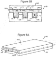
- Figures 5A-7 illustrate examples.
- the housing 102 of the device 100 can comprise a base (e.g., a substrate) 502 on which is disposed one or more micro-fluidic structures 500.
- the base 502 can comprise, for example, the lower wall 206 as discussed above with respect to Figure 2 , and all or part of the top surfaces of the micro-fluidic structure 500 can comprise the upper wall 202 including any variation discussed above.
- the micro-fluidic structure 500 can comprise a channel 504 and pens 506, each of which can comprise an enclosure 510 and an opening 508 to the channel 504.
- the pens 506 and the channel 504 can be the same or a different height from the base 502.
- the channel 504 and pens 506 can correspond to the chamber 110 of Figure 1A-1C and 2
- the surface 522 of the base 502 can correspond to the inner surface 120 of the chamber 110 of Figures 1A-1C and 2 .
- DEP electrodes can be activated and deactivated in accordance with the light pattern 216 at the surface 522 of the base 502 rather than the inner surface 120 of the chamber 110.
- One or more micro-objects 116 can be deterministically selected and moved (e.g., using the detector 220 and selector 118 as discussed above) from the channel 504 (which can be an example of a common space and/or a flow path) through the opening 508 into the enclosure 510 of a pen 506.
- the micro-object(s) 116 can then be held for a period of time in the pen 506.
- the opening 508 and enclosure 510 of each pen can be sized and configured and the rate of the flow 520 of media 114 in the channel 504 can be such that the flow 520 creates little to no appreciable convection inside the enclosure 510.
- micro-object(s) 116 thus tend to stay in the pen 506 until actively removed from the pen 506. Diffusion through the opening 508 between media 114 in the channel 504 and the enclosure 510 can provide for inflow into the enclosure 510 from the channel 504 of nutrients for the micro-object(s) 116 in a pen 506 and outflow from the enclosure 510 into the channel 504 of waste from the micro-object(s) 116.
- the pens 506 can be structured so that a first medium 122 in the flow 520 in the channel 504 does not flow directly into any of the pens 506, but the structure of the pens 506 allows diffusive mixing of the first medium 122 from the flow 520 through the opening 508 in the pen 506 with a second medium 124 inside the pen 506 generally as discussed above.
- the channel 504 and the pens 506 can be physical structures as shown in Figures 5A and 5B .
- the micro-fluidic structure 500 can comprise a flexible material (e.g. rubber, plastic, an elastomer, polydimethylsioxane ("PDMS"), or the like), which can also be gas permeable in some embodiments.
- the micro-fluidic structure 500 can comprise other materials including rigid materials.
- a virtual door 512 can optionally be created and removed closing and opening the opening 508 of each of the pens 506.
- Such virtual doors 512 can be created by activating DEP electrodes at the surface 522 of the base 502 generally as discussed above with regard to the inner surface 120.
- channel 504 and pens 506 are illustrated in Figures 5A and 5B as physical, the channel 504 and pens 506 can alternatively be virtual. For example, all or part of the channel 504 and/or the pens 506 can be created by activating DEP electrodes at the surface 522 of the base 502 generally as discussed above.
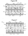
- the housing 102 of the device 100 can comprise the base 502 of Figures 5A and 5B and a micro-fluidic structure 602 disposed on the surface 522 of the base 502.
- the micro-fluidic structure 602 can comprise a pen structure 612, which can comprise pens 606.
- Each such pen 606 can comprise an enclosure 610 in which a micro-object 116 can be placed and held for a time period.
- the micro-fluidic structure 602 can define channels 604, and the opening 608 of each pen 606 can be in fluidic communication (e.g., contact) with media 114 in one of the channels 604.
- One or more micro-objects 116 can be deterministically selected (as discussed above) and moved from one of the channels 604 (which can be an example of a common space and/or a flow path) through the opening 608 into the enclosure 610 of a pen 606.
- the micro-object(s) 116 can then be held in a pen 606 for a period of time. Thereafter, the micro-object(s) 116 can be moved from the enclosure 610 through the opening 608 into the channel 604.
- Flows 620 of media 114 in the channels 604 can move micro-objects 116 in the channels 604.
- the flows 620 of media 114 in the channels 604 can provide nutrients to the micro-objects 116 in the pens 606 and allow for the outflow of waste from the micro-objects 116 during the period of time that the micro-objects 116 are held in the pens 606.
- the flows 620 in the channels 604 can thus constitute a common flow of media 114 to the pens 606, which like pens 506, can otherwise physically separate and isolate micro-objects 116.
- the pens 606 can be structured so that a first medium 122 in a flow 620 in a channel 604 does not flow directly into any of the pens 606, but the structure of the pens 606 allows diffusive mixing of the first medium 122 from a flow 620 through an opening 608 in the pen 606 with a second medium 124 in a pen 606.
- a pen 606 can be physical (rather than virtual) and the opening 608 of the pen 606 can be oriented in any direction so long as no part of the opening 608 faces directly into a flow 620. A pen 606 can thus impede direct flow of the first medium 122 into the pen 606.
- the pens 606 can be physical structures as shown in Figure 6B .
- the micro-fluidic structure 600 can comprise any of the materials discussed above with respect to the micro-fluidic structure 500 of Figures 5A and 5B .
- two channels 604 and twelve pens 606 are shown in Figure 6B
- the micro-fluidic structure 602 can comprise more or less than two channels 604 and more or fewer than twelve pens 606.
- a virtual door like door 512 of Figure 5B can optionally be created at the openings 608 of one or more of the pens 606.
- micro-fluidic structure 602 including the pen structure 612 are shown in Figures 6A and 6B as physical, all of part of the structure 602 can alternatively be virtual and thus created by activating DEP electrodes at the surface 522 of the base 502 as discussed above with respect to the inner surface 120.
- all or part of the pen structure 612 can be virtual rather than physical.
- Figure 7 is similar to Figure 6B except that a channel 704 (which can be an example of a flow path 126) is disposed between pen structures 712 as shown. Otherwise, each pen 706 can be similar to each pen 606.
- each pen 706 can comprise an enclosure 710 in which a micro-object 116 can be placed and held.
- the opening 708 of each pen 706 can be in fluidic communication (e.g., contact) with media 114 in the channel 704.
- One or more micro-objects 116 can be deterministically selected (as discussed above) and moved from the channel 704 (which can be an example of a common space) through the opening 708 into the enclosure 710 of a pen 706, where the micro-object(s) 116 can be held for a period of time. Thereafter, the micro-object(s) 116 can be moved from the enclosure 710 through the opening 708 into the channel 704.
- the flow 720 of media 114 in the channels 704 can move micro-objects 116 in the channel 704.
- the micro-objects 116 can be moved by DEP forces, centrifugal forces, and/or the like.
- the flow 720 of media 114 in the channel can also provide nutrients to the micro-objects 116 in the pens 706 and provide for the outflow of waste from the micro-objects 116 during the period of time that the micro-objects 116 are held in the pens 706.
- the flow 720 in the channel 704 can thus constitute a common flow of media 114 to all of the pens 706.
- the pens 706 can be structured so that a first medium 122 in the flow 720 in the channel 704 does not flow directly into any of the pens 706, but the structure of the pens 706 allows diffusive mixing of the first medium 122 in the channel 704 through an opening 708 in the pen 706 with second medium 124 in a pen 706.
- a pen 706 can be physical and can be oriented so that no opening to the pen 706 faces directly into the flow 720.
- FIG. 7 Although one channel 704 and twelve pens 706 are shown in Figure 7 , there can be more or fewer. Although not shown, a virtual door like door 512 of Figure 5B can optionally be created at the openings 708 of one or more of the pens 706. Although the pen structures 712 are shown in Figure 7 as physical, all or part of the pen structures 702 can alternatively be virtual and thus created by activating DEP electrodes at the surface 522 of the base 502 as discussed above with regard to inner surface 120.
- any of the pens 506, 606, 706 (or any pen disclosed herein) illustrated in Figures 5A-7 are examples only, and those pens 506, 606, 706 (or any pen disclosed herein) can take other shapes and/or configurations.
- any of pens 506, 606, 706 (or any pen disclosed herein) can be circular, oval, triangular, or the like rather than square or rectangular.
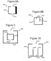
- any of the pens 506, 606, 706 (or any pen disclosed herein) can be replaced by the pen 806, 826, 906, 926 illustrated in Figures 8A-10 .
- a pen 806 can comprise an opening 812 (e.g., corresponding to openings 506, 606, 706) that is smaller than the full width of the enclosure 810 (e.g., corresponding to enclosures 510, 610, 710).
- a pen 806 can comprise one or more secondary openings 814 (one is shown but there can be more).
- the opening 812 can be larger than a micro-object 116 (not shown in Figure 8A ), and the secondary opening 814 can be smaller than a micro-object 116.
- the secondary opening 814 can allow, for example, media 114 (not shown in Figure 8A ) to flow into or out of the pen 806.
- media 114 can flow into the pen 806 through the opening 812 and out of the pen 806 through the secondary opening 814.
- the walls of a pen need not be the same thickness.
- a pen 826 can comprise an inner wall 834 that extends from an opening 832 (e.g., corresponding to openings 508, 608, 708, 812) to create an inner containment space 836 within the enclosure 840 (e.g., corresponding to enclosures 510, 610, 710).
- a pen 906 can comprise one or more additional pens 916 (one is shown but there can be more).
- one or more inner pens 916 (one is shown but there can be more) comprising an opening 922 and an enclosure 920 can be disposed inside the enclosure 910 of an outer pen 906, which can comprise opening 912.
- One or more micro-objects 116 (not shown in Figure 9 ) can be disposed in the enclosure of each inner pen 916 and the outer pen 906.
- a pen 926 (comprising an opening 932 and enclosure 930) can comprise multiple holding spaces 936 (although three are shown, there can be more or fewer) separated by interior walls 934.
- One or more micro-objects 116 (not shown in Figure 10 ) can be disposed in each holding space 936.
- a different type of micro-object 116 can be disposed in each holding space 936.
- any of the pens disclosed herein can be configured to be like or to have any of the characteristics of the pens 806, 826, 906, 926 illustrated in Figures 8A-10 .
- micro-objects 116 can be deterministically selected and moved from the flows 520, 620, 720 in the channels 504, 604, 704 into pens 506, 606, 706 in Figures 5A-7 (including the variations of the pens 506, 606, 706 illustrated in Figures 8A-10 ) by any of a variety of mechanisms.
- Figures 11A-12B illustrate examples in which the OET device of Figure 2 is used to do so.
- the channel 1104 can be any of the channels 504, 604, 704;
- the pen 1106 can be any of the pens 506, 606, 706;
- the flow 1120 of media 114 can be any of the flows 520, 620, 720 in Figures 5A-7 .
- a micro-object 116 can be deterministically selected in the flow 1120 in the channel 1104 by creating a light trap 1108 (e.g., like light trap 304) that traps the micro-object 116, which can trap the micro-object 116 in the trap 1108.
- the light trap 1108 can then be moved from the channel 1104 into the pen 1106, where the micro-object 116 can be released from the light trap 1108.
- the light trap 1108 can be like and can be created and moved on the surface 522 of the base 502 by the OET device of Figure 2 in the same way as light traps 304, 412 are created and moved on the inner surface 120 as discussed above.
- a micro-object 116 can be deterministically selected in the flow 1120 in the channel 1104 by creating a virtual barrier 1208 in the path of the micro-object 116 in the channel 1104.
- the virtual barrier 1208 can deflect the micro-object 116 into the pen 1106.
- the virtual barrier 1208 can be created by activating DEP electrodes on the surface 522 of the base 502 using the OET device of Figure 2 generally as discussed above. Once the selected micro-object 116 is deflected into the pen 1106, the virtual barrier 1208 can be removed from the channel 1104.
- micro-objects 116 can be contained in any of the pens disclosed herein for a period of time after which the micro-objects 116 can be removed from the pens. In some embodiments, micro-objects 116 can be removed from pens in any of the ways illustrated in Figures 11A-12B .
- a light trap 1108 can be formed that traps a micro-object 116 in a pen 1106 and the light trap 1108 can be moved out of the pen 1106 into the channel 1104, which is the reverse of the process shown in Figures 11A and 11B . Once in the channel 1104, the light trap 1108 can be turned off, releasing the micro-object 116 into the flow 1120 of media 114 in the channel 1104.
- a virtual barrier similar to the barrier 1208 shown in Figures 12A and 12B can be formed in a pen 1106 to nudge a micro-object 116 out of the pen 1106 into the flow 1120 of media 114 in the channel 1104.
- the foregoing is the reverse of the process shown in Figures 12A and 12B .
- any of the physical pens disclosed herein can be configured like the outputting mechanisms 800 disclosed in the aforementioned US patent application serial no. 13/856,781 (attorney docket no. BL1-US).
- the pens can be configured like the expressing mechanism 804 in the foregoing patent application, and a striking mechanism (not shown) like the striking mechanism 802 in the foregoing patent can be provided to express the micro-objects 116 from the pens.
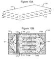
- Figures 13A and 13B illustrate a micro-fluidic device 1300 that can be an example of the device 100 of Figures 1A-1C in which the base 502 and a micro-fluidic structure 1302 are examples of the housing 102, the chamber 1308 is an example of the chamber 110, the inlet 1314 is an example of the inlet 104, the outlet 1316 is an example of the outlet 106, and the pens 1306 are examples of the pens 112. (Compare to Figures 1A-1C .)
- the device 1300 can comprise a micro-fluidic structure 1302 disposed on the base 502 (which is described above with respect to Figures 5A and 5B ).
- the micro-fluidic structure 1302 and base 502 can define a chamber 1308 for media 114 and micro-objects 116.
- Media 114 with micro-objects 116 can be input into the chamber 1308 through an inlet 1314 and output from the chamber 1308 through an outlet 1316.
- a flow 1320 of media 114 can thus be provided in the chamber 1308 from the inlet 1314 to the outlet 1316.
- the inlet 1314 and outlet 1316 can be the same as or similar to the inlet 104 and outlet 106 of Figures 1A-1C as discussed above.
- the channels 1304 are examples of common spaces and/or flow paths for media 114.
- a gas exchanger 1310 and an array 1312 of pens 1306 and channels 1304 can be disposed in the chamber 1308 between the inlet 1314 and the outlet 1316 and thus in the flow 1320 of media 114.
- the flow 1320 of media 114 can thus pass from the inlet 1314 through the gas exchanger 1310, through the channels 1304 of the pen array 1312, and out the outlet 1316.
- the inlet 1314 can be located between the gas exchanger 1310 and the pens 1304, and the gas exchanger 1310 can thus be located upstream from the inlet 1314.
- the channels 1304 and pens 1306 can be like any of the channels and pens discussed herein.
- the channels 1304 can be like any of channels 504, 604, 704, 1104, 1204 including any variation of those channels discussed above
- the pens 1306 can be like any of pens 112, 302, 402, 506, 606, 706, 806, 906, 1106, 1206 including any variation of those pens discussed above.
- Openings of the pens 1306 can be in fluidic communication (e.g., contact) with one of the channels 1304.
- micro-objects 116 (not shown in Figures 13A and 13B ) move with the flow 1320 of media 114, ones of the micro-objects 116 can be selected in a channel 1304 and moved into a pen 1306.
- a micro-object 116 can be deterministically selected in a channel 1304 and moved into a pen 1306 using any technique or mechanism discussed above (e.g., with light traps like light traps 304, 412, 1108; with a virtual barrier like barrier 1208; or the like).
- the flow 1320 of media 114 can also be a common flow that carries nutrients to and provides for the outflow of waste from micro-objects 116 in the pens 1306, which can otherwise isolate micro-objects 116 from each other.
- each of the pens 1306 can be structured so that media 114 (e.g., the first medium 122 shown in Figures 1B and 1C ) in a flow 1320 in a channel 1304 does not flow directly into any of the pens 1306, but the structure of each pen 130 can allow diffusive mixing of media 114 from a flow 1320 in a channel 1304 and media 114 (e.g., the second medium 124 shown in Figures 1B and 1C ) in a pen 1306 generally as discussed above.
- the configuration of the pen array 1312 in Figure 13B is but an example.
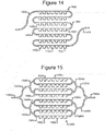
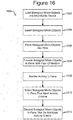
- Figures 14 and 15 illustrate examples of alternative configurations.
- a pen array 1400 can comprise rows of pens 1402, and openings of the pens 1402 can be in fluidic communication (e.g., contact) with a single channel 1404.
- the pen array 1400 and channel 1404 can replace the pen array 1312 and channels 1304 in Figure 13B , and the flow 1320 of media 114 in Figure 13B can be through the channel 1404.
- the pen array 1500 and channels 1504 in Figure 15 can also replace the pen array 1312 and channels 1304 in Figure 13B .
- the pen array 1500 can comprise rows of pens 1502 with openings in direct fluidic communication with channels 1504c.
- a plurality of first branching channels 1504b can connect an input channel 1504a to the channels 1504c that flow directly past the pens 1502.
- Other (second) branching channels 1504d can connect the channels 1504c to an output channel 1504e.
- the flow 1320 of media 114 in Figure 13B can be into the first channel 1504a, through branching channels 1504b to the channels 1504c in direct fluidic communication with the pens 1502, through other branching channels 1504d to the second channel 1504e.
- the channels 1404, 1504 in Figures 14 and 15 can be like channels 1304 as discussed above.
- the pens 1402, 1502 can likewise be like pens 1306 as discussed above.
- the channels 1404, 1504 can be examples of common spaces and/or flow paths.
- Each pen 1402, 1502 can be structured so that media 114 (e.g., the first medium 122 in Figures 1B and 1C ) in a flow in a channel 1404, 1504 does not flow directly into the pen 1402, 1502, but the structure of each pen 1402, 1502 can allow diffusive mixing of media from a flow in a channel 1404, 1504 and media (e.g., the second medium 124 in Figures 1B and 1C ) in a pen 1402, 1502 generally as discussed above.
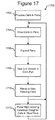
- Figure 16 illustrates an example of a process 1600 for processing biological micro-objects in pens.
- the process 1600 can be performed using any of the micro-fluidic devices discussed above or similar devices.
- the process 1600 can be performed using the micro-fluidic devices 100 and 1300 including any variation of those devices discussed above (e.g., as illustrated in Figures 2-12B , 14, and 15 ).
- the process 1600 can load biological micro-objects into a micro-fluidic device.
- the process 1600 can introduce into the chamber 110 of the device 100 of Figures 1A-1C through the inlet 104 micro-objects 116 in media 114.
- the process 1600 can introduce into the chamber 1308 of the device 1300 of Figures 13A and 13B micro-objects 116 in media 114 through the inlet 1314.
- the process can select individual ones of the biological micro-objects loaded at step 1602. For example, the process 1600 can select a sub-set of less than all of the micro-objects 116 in media 114 that have a particular characteristic.
- the micro-objects 116 can be monitored, for example, using the imaging device 220 of Figure 2 .
- one micro-object 116 having a particular desired characteristic can be deterministically selected and loaded into one pen such that step 1604 results in one and only one micro-object 116 in each of a plurality of the pens.
- more than one micro-object 116 can be loaded into a pen.
- the process 1600 can place the micro-objects 116 selected at step 1604 into pens of the micro-fluidic device.
- the process 1600 can place selected micro-objects 116 into the pens 112, 302, 402, 506, 606, 706, 806, 906, 1106, 1206, 1306, 1402, 1502 using any of the techniques discussed above.
- the foregoing pens can physically separate micro-objects 116 one from another. That is, each pen can physically separate the micro-object 116 or micro-objects 116 in the pen from all other micro-objects 116 in the micro-fluidic device 100, 1300.
- the process 1600 can keep the micro-objects 116 in the pens for a time period.
- the process 1600 can provide a flow of liquid media 114 to the pens.
- Step 1608 can be accomplished by providing any of the flows 314, 314, 520, 620, 720, 1120, 1320 in the chambers 110, 1308 or channels 504, 604, 704, 1104 as discussed. It is noted that, at step 1606, individual micro-objects 116 can be physically isolated from each other by being placed in physically separated pens, but at step 1608, those micro-objects 116 in the pens can be provided with the same flow of media 114.
- the pens 112, 302, 402, 506, 606, 706, 806, 906, 1106, 1206, 1306, 1402, 1502 can be structured to impede direct flow of media 114 (e.g., the first medium 122 shown in Figures 1B and 1C ) from the flows 314, 314, 520, 620, 720, 1120, 1320 in the chambers 110, 1308 or channels 504, 604, 704, 1104 into the pens 112, 302, 402, 506, 606, 706, 806, 906, 1106, 1206, 1306, 1402, 1502 while allowing diffusive mixing of media 114 (e.g., the first medium 122 shown in Figures 1B and 1C ) from the flows 314, 314, 520, 620, 720, 1120, 1320 and media 114 (e.g., the second medium 124 shown in Figures 1B and 1C ) inside the pens.
- media 114 e.g., the first medium 122 shown in Figures 1B and 1C
- the micro-objects 116 placed into the pens at step 1606 can be kept in the pens for a time period during which step 1608 can provide the micro-objects 116 with the flow of media 114, which through the diffusive mixing discussed above can provide the micro-objects 116 in the pens with nutrients and provide for the outflow of waste from the micro-objects 116.
- the process 1600 can monitor one or more biological activities of the micro-objects 116 in the pens. Examples of such biological activities can include clone production, secretion of certain biological substances, or the like.
- the monitoring at step 1610 can be continuous during the time period, periodically during the time period, at the end of the time period, or the like.
- the monitoring at step 1610 can be performed in any manner suitable for analyzing biological activities of the micro-objects 116.
- the monitoring at step 1610 can be performed using the imaging system 220 of Figure 2 , with sensors (not shown) in or adjacent the pens, or the like.
- the process 1600 can select the micro-objects 116 in the pens that meet a predetermined criteria, threshold, or condition associated with the biological activity or state monitored at step 1610.
- the micro-objects 116 selected at step 1612 can be removed from the pens for further processing or use.
- the selected micro-objects 116 can be removed from the pens using any technique or process discussed above.
- one or more micro-objects 116 can be removed from a pen by piercing the housing with a needle-like aspirator (not shown), and removing the micro-objects 116 with the aspirator.
- a specific, controlled number of micro-objects 116 can be removed, for example, by selecting and removing that number of micro-objects 116 or, if the micro-objects 116 are biological cells, removing all of the cells when a colony of cloned cells reaches the desired number.
- the process 1600 can discard the micro-objects 116 not selected at step 1612, which are the micro-objects 116 that do not meet the predetermined criteria, threshold, or condition associated with the biological activity or state monitored at step 1610.
- Figure 17 illustrates an example process 1700 for growing colonies of cloned cells from a single parent cell according to some embodiments of the invention.
- the process 1700 can be an example of the process 1600 of Figure 16 .
- the process 1700 can start after steps 1602 and 1604 of Figure 16 are performed; steps 1702-1706 can be performed during steps 1606 and 1608; step 1708 can be an example of step 1610; step 1710 can be an example of step 1614; and step 1712 can be an example of step 1612.
- process 1700 is discussed below as performed with the device 100 configured with the OET device of Figure 2 for creating and manipulating the virtual pens 302 of Figure 3 .
- the process 1700 can be performed with other configurations of the device 100 or the device 1300 in which the pens are virtual pens.
- the process 1700 can process cells in pens. Such processing can include fusing two cells into one cell, transfecting a cell by injecting a biological vector into a cell, or the like.
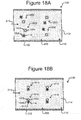
- Figures 18A-18C illustrate an example.
- FIG. 18A two different types of micro-objects 116 and 1804 can be placed in media 114 in the chamber 110.
- the OET device of Figure 2 can generate light traps 1806, 1808 (e.g., like light trap 304) to select one of the first cell type 116 and one of the second cell type 1804.
- the light traps 1806 and 1808 can then be moved into contact such that the first cell type 116 and the second cell type are in contact as shown in Figure 18B .
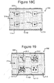
- Such paired cells 1810 can then be subjected to one or more treatments (e.g., including in the flow 314 a fusing chemical (e.g., polyethylene glycol (PEG), the Sendai virus, piercing the membranes of one of the cells 116, 1804, electric fields, pressure, or the like)) that fuse the paired cells 1810 together to form a fused cell 1812 as shown in Figure 18C .
- a fusing chemical e.g., polyethylene glycol (PEG), the Sendai virus, piercing the membranes of one of the cells 116, 1804, electric fields, pressure, or the like
- each fused cell 1812 can comprise one of the first cell types 116 and one of the second cell types 1804 fused together.
- the light traps 1806 and 1808 can be like and can be created and manipulated like the light trap 304, 412 as discussed above including any variation thereof.
- individual fused cells 1812 can be placed in virtual pens 1814, 1816, 1818, 1820. Although four pens 1814, 1816, 1818, 1820 are shown, there can be more or fewer.
- the virtual pens 1814, 1816, 1818, 1820 can be the same as or similar to the pens 302 of Figure 3 as described above.
- element 1804 in Figures 18A can be a biological vector to be transfected into a micro-object 116.
- each cell 1812 in Figure 18C can be one of the micro-objects 116 transfected with a vector 1804.
- cells 1812 in Figure 18C can be processed in another device and then placed into the pens 1814, 1816, 1818, 1820.
- step 1702 is not included in the process of Figure 17 .
- cells 1812 can be simple cells rather than fused or transfected cells.
- clones can be grown in each pen 1814, 1816, 1818, 1820 from the cell 1812 in the pen. This can be facilitated by including a growth medium in the flow 314 through the chamber 114.
- the pens 1814, 1816, 1818, 1820 can be expanded as the clones grow in each pen.
- Figure 19 illustrates an example. As shown in Figure 19 , as the number of cells 1812 in each pen 1814, 1816, 1818, 1820 increases, the size of the pens 1814', 1816', 1818', 1820' can be expanded to accommodate the growing clone populations in each pen.
- each pen 1814, 1816, 1818, 1820 can be examined and clone growth in the pen can be analyzed.
- a fluorescent label e.g., a biological fluorescent compound that fluoresces when stimulated or otherwise
- the level that each pen 1814, 1816, 1810, 1820 fluoresces can then be analyzed to determine clone growth in each pen.
- the clones in the pens 1814, 1816, 1818, 1820 in which the clones 1812 are growing at less than a minimum amount (or are otherwise undesirable) can be discarded.
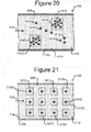
- Figure 20 illustrates an example. For purposes of the example illustrated in Figure 20 , it is assumed that at step 1710 it was determined that the clones 1812 in pens 1814', 1820' of Figure 19 grew less than a minimum threshold amount and are to be discarded. As shown in Figure 20 , the pens 1814', 1820' can be turned off, freeing the clones 1812 in those pens.
- the pens 1814', 1820' can be turned off simply by removing from the light pattern 216 being directed into the housing 102 Figure 2 the light that corresponds to pens 1814', 1820'.
- the now freed clones 1812 that were in pens 1814', 1820' can be flushed out of the chamber 110 (e.g., by flow 314) and discarded.
- the steps 1704 through 1710 can be repeated to continue growing clones 1812 in the pens 1816', 1818'.
- individual ones of the clones 1812 from pens 1814', 1820' can be selected and placed as daughter clones in new pens, and the steps 1704 through 1710 can be repeated to grow, test, and discard slow growers in the new pens.
- Figure 21 shows an example in which individual daughter clones 1812 from the pens 1816', 1818' in Figure 20 are selected and each placed in a new pen 2102.
- the new pens 2102 can be created and manipulated in the same way that pens 1814, 1816, 1818, 1820 are created and manipulated as discussed above.
- Individual daughter clones 1812 can be selected and moved generally as discussed above (e.g., with light traps like light trap 304, 412 of Figure 4 ).
- Figure 22 illustrates a process 2200 that is a variation of the process 1700 of Figure 17 .
- one or more cells can be held in and secrete into the pens.
- a cell 1812 can be disposed in each of the pens 1814, 1816, 1818, 1820.
- the cells 1812 can be fused or transfected cells as discussed above with respect to Figures 18A-18C .
- cells 1812 can be simple cells rather than fused or transfected cells.
- each pen 1814, 1816, 1818, 1820 can be examined and the productivity of the cells 1812 in the pen can be analyzed.
- one or more cells 1812 can be removed from each pen 1814, 1816, 1818, 1820 and observed, tested, or the like to determine the secretion productivity of the removed cells 1812.
- the pens 1814, 1816, 1818, 1820 in which the cells 1812 are secreting at less than a threshold level can be discarded. This can be accomplished generally as shown in Figure 20 and discussed above. That is, pens 1814, 1816, 1818, 1820 that contain low producing cells 1812 can be turned off and the low performing cells 1812 washed away generally in accordance with the discussion of Figure 20 above.
- the steps 2202 through 2206 can be repeated to continue to have the cells 1812 in the remaining pens secrete, to test the secretion productivity of the cells in each pen, and discard cells 1812 in low producing pens.
- individual ones of the high producing cells 1812 can be selected and placed as daughter cells in new pens (e.g., generally in accordance with the example shown in Figure 21 ), and the steps 2202 through 2206 can be repeated to have the daughter cells secrete in their new pens, test the secretion productivity of the daughter cells in each pen, and discard daughter cells in low secreting pens.
Applications Claiming Priority (4)
| Application Number | Priority Date | Filing Date | Title |
|---|---|---|---|
| US201261720956P | 2012-10-31 | 2012-10-31 | |
| US14/060,117 US9857333B2 (en) | 2012-10-31 | 2013-10-22 | Pens for biological micro-objects |
| EP13850976.5A EP2914965B1 (fr) | 2012-10-31 | 2013-10-30 | Crayons pour micro-objets biologiques |
| PCT/US2013/067479 WO2014070873A1 (fr) | 2012-10-31 | 2013-10-30 | Crayons pour micro-objets biologiques |
Related Parent Applications (2)
| Application Number | Title | Priority Date | Filing Date |
|---|---|---|---|
| EP13850976.5A Division-Into EP2914965B1 (fr) | 2012-10-31 | 2013-10-30 | Crayons pour micro-objets biologiques |
| EP13850976.5A Division EP2914965B1 (fr) | 2012-10-31 | 2013-10-30 | Crayons pour micro-objets biologiques |
Publications (1)
| Publication Number | Publication Date |
|---|---|
| EP3885043A1 true EP3885043A1 (fr) | 2021-09-29 |
Family
ID=50545993
Family Applications (2)
| Application Number | Title | Priority Date | Filing Date |
|---|---|---|---|
| EP21154105.7A Pending EP3885043A1 (fr) | 2012-10-31 | 2013-10-30 | Crayons pour micro-objets biologiques |
| EP13850976.5A Active EP2914965B1 (fr) | 2012-10-31 | 2013-10-30 | Crayons pour micro-objets biologiques |
Family Applications After (1)
| Application Number | Title | Priority Date | Filing Date |
|---|---|---|---|
| EP13850976.5A Active EP2914965B1 (fr) | 2012-10-31 | 2013-10-30 | Crayons pour micro-objets biologiques |
Country Status (12)
| Country | Link |
|---|---|
| US (4) | US9857333B2 (fr) |
| EP (2) | EP3885043A1 (fr) |
| JP (3) | JP6529908B2 (fr) |
| KR (3) | KR101998918B1 (fr) |
| CN (2) | CN108070582B (fr) |
| AU (3) | AU2013337937B2 (fr) |
| CA (1) | CA2888810C (fr) |
| DK (1) | DK2914965T3 (fr) |
| HK (3) | HK1249131A1 (fr) |
| IL (2) | IL272535B2 (fr) |
| SG (2) | SG10201606540RA (fr) |
| WO (1) | WO2014070873A1 (fr) |
Families Citing this family (64)
| Publication number | Priority date | Publication date | Assignee | Title |
|---|---|---|---|---|
| US9889445B2 (en) | 2013-10-22 | 2018-02-13 | Berkeley Lights, Inc. | Micro-fluidic devices for assaying biological activity |
| CN110437975B (zh) * | 2013-10-22 | 2023-06-09 | 伯克利之光生命科技公司 | 具有隔离围栏的微流体装置及用它测试生物微目标的方法 |
| WO2015061506A1 (fr) * | 2013-10-22 | 2015-04-30 | Berkeley Lights, Inc. | Dispositifs microfluidiques pour dosage d'activité biologique |
| US10010882B2 (en) * | 2013-10-22 | 2018-07-03 | Berkeley Lights, Inc. | Microfluidic devices having isolation pens and methods of testing biological micro-objects with same |
| US20150166326A1 (en) | 2013-12-18 | 2015-06-18 | Berkeley Lights, Inc. | Capturing Specific Nucleic Acid Materials From Individual Biological Cells In A Micro-Fluidic Device |
| US11192107B2 (en) | 2014-04-25 | 2021-12-07 | Berkeley Lights, Inc. | DEP force control and electrowetting control in different sections of the same microfluidic apparatus |
| US20150306598A1 (en) * | 2014-04-25 | 2015-10-29 | Berkeley Lights, Inc. | DEP Force Control And Electrowetting Control In Different Sections Of The Same Microfluidic Apparatus |
| US20150306599A1 (en) | 2014-04-25 | 2015-10-29 | Berkeley Lights, Inc. | Providing DEP Manipulation Devices And Controllable Electrowetting Devices In The Same Microfluidic Apparatus |
| WO2016090295A1 (fr) | 2014-12-05 | 2016-06-09 | The Regents Of The University Of California | Dispositif microfluidique simple face, actionné par la lumière, à terre à mailles intégrée |
| CN110918142B (zh) | 2014-12-08 | 2022-10-25 | 伯克利之光生命科技公司 | 微流体装置中定向流动的致动微流体结构及使用它的方法 |
| DK3229958T3 (da) | 2014-12-08 | 2020-11-30 | Berkeley Lights Inc | Mikrofluidanordning, der omfatter laterale/vertikale transistorstrukturer, samt fremgangsmåde til fremstilling og anvendelse heraf |
| WO2016094459A2 (fr) | 2014-12-09 | 2016-06-16 | Berkeley Lights, Inc. | Détection automatique et repositionnement de micro-objets dans des dispositifs microfluidiques |
| CN107206377B (zh) | 2014-12-09 | 2020-02-11 | 伯克利之光生命科技公司 | 微流体装置中测定阳性的区域的自动检测 |
| WO2016094715A2 (fr) * | 2014-12-10 | 2016-06-16 | Berkeley Lights, Inc. | Déplacement et sélection de micro-objets dans un appareil micro-fluidique |
| KR20230125849A (ko) | 2014-12-10 | 2023-08-29 | 버클리 라잇츠, 인크. | 전기역학적 디바이스들을 동작시키기 위한 시스템들 |
| EP3270801A4 (fr) * | 2015-03-04 | 2018-12-12 | Berkeley Lights, Inc. | Production et sélection d'embryons in vitro |
| JP2018512116A (ja) * | 2015-03-04 | 2018-05-17 | バークレー ライツ,インコーポレイテッド | in vitroでの胚の作成及び選択 |
| JP2018512875A (ja) | 2015-04-22 | 2018-05-24 | バークレー ライツ,インコーポレイテッド | マイクロ流体デバイスにおける細胞の凍結及び保管 |
| JP7051206B2 (ja) | 2015-04-22 | 2022-04-11 | バークレー ライツ,インコーポレイテッド | マイクロ流体細胞培養 |
| TWI744230B (zh) * | 2015-04-22 | 2021-11-01 | 美商伯克利之光生命科技公司 | 微流體器件及在該微流體器件中培養生物細胞之方法 |
| US10751715B1 (en) | 2015-04-22 | 2020-08-25 | Berkeley Lights, Inc. | Microfluidic reporter cell assay methods and kits thereof |
| WO2016172623A1 (fr) * | 2015-04-22 | 2016-10-27 | Berkeley Lights, Inc. | Manipulation de noyaux cellulaires dans un dispositif microfluidique |
| US10799865B2 (en) | 2015-10-27 | 2020-10-13 | Berkeley Lights, Inc. | Microfluidic apparatus having an optimized electrowetting surface and related systems and methods |
| CN108472649B (zh) * | 2015-10-27 | 2022-01-14 | 伯克利之光生命科技公司 | 具有优化的电润湿表面的微流体装置和相关系统及方法 |
| JP7296210B2 (ja) * | 2015-11-23 | 2023-06-22 | バークレー ライツ,インコーポレイテッド | インサイチュー生成マイクロ流体分離構造、そのキット、及びその使用方法 |
| US11208649B2 (en) | 2015-12-07 | 2021-12-28 | Zymergen Inc. | HTP genomic engineering platform |
| US9988624B2 (en) | 2015-12-07 | 2018-06-05 | Zymergen Inc. | Microbial strain improvement by a HTP genomic engineering platform |
| DK3387438T3 (da) | 2015-12-08 | 2023-05-15 | Berkeley Lights Inc | Mikrofluidiske indretninger og kits samt fremgangsmåder til anvendelse heraf |
| EP3397586A4 (fr) | 2015-12-30 | 2019-07-17 | Berkeley Lights, Inc. | Dispositifs microfluidiques pour convection et déplacement à commande optique, kits et procédés associés |
| WO2017117521A1 (fr) | 2015-12-31 | 2017-07-06 | Berkeley Lights, Inc. | Cellules infiltrant les tumeurs, modifiées pour exprimer un polypeptide pro-inflammatoire |
| JP6902548B2 (ja) * | 2016-01-15 | 2021-07-14 | バークレー ライツ,インコーポレイテッド | 患者特異的抗癌治療剤の製造方法及びその治療方法 |
| CN109922885B (zh) | 2016-03-16 | 2022-05-10 | 伯克利之光生命科技公司 | 用于基因组编辑克隆的选择和传代的方法、系统和装置 |
| CN115354025A (zh) * | 2016-03-17 | 2022-11-18 | 伯克利之光生命科技公司 | 微流体装置中t淋巴细胞的选择和克隆 |
| KR102451535B1 (ko) | 2016-03-31 | 2022-10-05 | 버클리 라잇츠, 인크. | 핵산 안정화 시약, 키트들, 및 그 이용 방법들 |
| KR102421818B1 (ko) | 2016-04-15 | 2022-07-15 | 버클리 라잇츠, 인크. | 펜 내 분석들을 위한 방법들, 시스템들 및 키트들 |
| US10675625B2 (en) | 2016-04-15 | 2020-06-09 | Berkeley Lights, Inc | Light sequencing and patterns for dielectrophoretic transport |
| SG11201809539RA (en) | 2016-05-26 | 2018-12-28 | Berkeley Lights Inc | Covalently modified surfaces, kits, and methods of preparation and use |
| ES2802261T3 (es) | 2016-06-21 | 2021-01-18 | Quantumdx Group Ltd | Concentración de células diana mejorada mediante dielectroforesis (DEP) |
| WO2018018017A1 (fr) | 2016-07-21 | 2018-01-25 | Berkeley Lights, Inc. | Tri de lymphocytes t dans un dispositif microfluidique |
| AU2017336164A1 (en) | 2016-10-01 | 2019-04-18 | Berkeley Lights, Inc. | DNA barcode compositions and methods of in situ identification in a microfluidic device |
| JP2019537157A (ja) | 2016-12-01 | 2019-12-19 | バークレー ライツ,インコーポレイテッド | マイクロ流体デバイスによる微小物体の自動検出及び再配置 |
| SG10202104487WA (en) | 2016-12-01 | 2021-05-28 | Berkeley Lights Inc | Apparatuses, systems and methods for imaging micro-objects |
| WO2018111765A1 (fr) | 2016-12-12 | 2018-06-21 | xCella Biosciences, Inc. | Procédés et systèmes de criblage à l'aide de réseaux microcapillaires |
| CN110546495B (zh) | 2016-12-30 | 2022-11-01 | 加利福尼亚州立大学董事会 | 用于基因组编辑t细胞的选择和传代的方法 |
| WO2018207454A1 (fr) * | 2017-05-12 | 2018-11-15 | 株式会社ニコン | Dispositif et procédé de manipulation d'objet |
| KR20200026878A (ko) | 2017-06-06 | 2020-03-11 | 지머젠 인코포레이티드 | 균류 균주를 개량하기 위한 htp 게놈 공학 플랫폼 |
| WO2019067319A2 (fr) * | 2017-09-29 | 2019-04-04 | Schlumberger Technology Corporation | Technique micro-fluidique pour détection de miscibilité multi-contact |
| EP3721209B1 (fr) | 2017-10-15 | 2024-02-07 | Berkeley Lights, Inc. | Procédés pour essais « en enclos » |
| CN108300654B (zh) * | 2018-02-09 | 2021-08-17 | 华中科技大学同济医学院附属协和医院 | 评估可移动生物活体药代动力学的芯片及实时检测系统 |
| DE102018203047A1 (de) * | 2018-03-01 | 2019-09-05 | Robert Bosch Gmbh | Mikrofluidische Vorrichtung |
| US11041834B2 (en) | 2018-03-06 | 2021-06-22 | Waters Technologies Corporation | High surface area chromatographic device with low pressure drop |
| WO2019232473A2 (fr) | 2018-05-31 | 2019-12-05 | Berkeley Lights, Inc. | Détection et caractérisation automatiques de micro-objets dans des dispositifs microfluidiques |
| KR20210018219A (ko) | 2018-06-06 | 2021-02-17 | 지머젠 인코포레이티드 | 발효 및 생산 중 곰팡이 형태를 제어하기 위한 신호 전달에 포함된 유전자의 조작 |
| US10953408B2 (en) * | 2018-09-04 | 2021-03-23 | The Governing Council Of The University Of Toronto Banting Institute | Patterned optoelectronic tweezers |
| CA3112333A1 (fr) * | 2018-09-14 | 2020-03-19 | Berkeley Lights, Inc. | Procede pour analyser l'affinite d'une liaison |
| CN113166697A (zh) * | 2018-10-10 | 2021-07-23 | 斯塔姆韦格公司 | 连续流动式微型生物反应器 |
| CN114126762B (zh) | 2019-04-30 | 2023-01-03 | 伯克利之光生命科技公司 | 用于包封和测定细胞的方法 |
| TW202142856A (zh) | 2019-11-17 | 2021-11-16 | 美商伯克利之光生命科技公司 | 用於生物樣本之分析的系統及方法 |
| CA3169648A1 (fr) | 2020-02-03 | 2021-08-12 | Stamm Vegh Corporation | Plateforme, systemes et dispositifs pour l'impression en trois dimensions (3d) |
| KR20220166788A (ko) * | 2020-03-09 | 2022-12-19 | 버클리 라잇츠, 인크. | 펜내 분석을 위한 방법, 시스템 및 키트 |
| US11479779B2 (en) | 2020-07-31 | 2022-10-25 | Zymergen Inc. | Systems and methods for high-throughput automated strain generation for non-sporulating fungi |
| WO2023032827A1 (fr) | 2021-08-31 | 2023-03-09 | キヤノン株式会社 | Corps moulé non expansé contenant du polyuréthane |
| EP4239333A1 (fr) | 2022-03-03 | 2023-09-06 | Lonza Biologics plc | Procédé de sélection de cellules clonales exprimant des molécules de liaison multispécifiques assemblées correctement |
| WO2024076923A1 (fr) * | 2022-10-03 | 2024-04-11 | Bruker Cellular Analysis, Inc. | Déplacement de micro-objet dans un environnement microfluidique |
Citations (6)
| Publication number | Priority date | Publication date | Assignee | Title |
|---|---|---|---|---|
| US6958132B2 (en) | 2002-05-31 | 2005-10-25 | The Regents Of The University Of California | Systems and methods for optical actuation of microfluidics based on opto-electrowetting |
| WO2005100541A2 (fr) * | 2004-04-12 | 2005-10-27 | The Regents Of The University Of California | Pinces optoelectroniques pour la manipulation de microparticules et de cellules |
| WO2010147078A1 (fr) * | 2009-06-19 | 2010-12-23 | 国立大学法人東京大学 | Procédé de manipulation de particules et dispositif microfluidique |
| US7956339B2 (en) | 2007-03-28 | 2011-06-07 | The Regents Of The University Of California | Single-sided lateral-field and phototransistor-based optoelectronic tweezers |
| WO2011149032A1 (fr) * | 2010-05-26 | 2011-12-01 | 東ソー株式会社 | Dispositif de fixation d'échantillon biologique |
| WO2011160430A1 (fr) * | 2010-06-25 | 2011-12-29 | Capitalbio Corporation | Dispositif micro-fluidique intégré pour le piégeage d'un seul ovocyte |
Family Cites Families (50)
| Publication number | Priority date | Publication date | Assignee | Title |
|---|---|---|---|---|
| ES2288760T3 (es) | 1996-04-25 | 2008-01-16 | Bioarray Solutions Ltd. | Ensamblaje electrocinetico controlado por luz de particulas proximas a superficies. |
| US6294063B1 (en) | 1999-02-12 | 2001-09-25 | Board Of Regents, The University Of Texas System | Method and apparatus for programmable fluidic processing |
| US6942776B2 (en) | 1999-05-18 | 2005-09-13 | Silicon Biosystems S.R.L. | Method and apparatus for the manipulation of particles by means of dielectrophoresis |
| KR100865105B1 (ko) | 1999-06-28 | 2008-10-24 | 캘리포니아 인스티튜트 오브 테크놀로지 | 마이크로 가공된 탄성중합체 밸브 및 펌프 시스템 |
| US20030007894A1 (en) | 2001-04-27 | 2003-01-09 | Genoptix | Methods and apparatus for use of optical forces for identification, characterization and/or sorting of particles |
| ITTO20010411A1 (it) | 2001-05-02 | 2002-11-02 | Silicon Biosystems S R L | Metodo e dispositivo per l'esecuzione di test e saggi ad alta processivita' ed alto valore biologico su cellule e/o composti. |
| US7075162B2 (en) * | 2001-08-30 | 2006-07-11 | Fluidigm Corporation | Electrostatic/electrostrictive actuation of elastomer structures using compliant electrodes |
| CN1291035C (zh) * | 2001-10-09 | 2006-12-20 | 清华大学 | 用于样品制备和分析的集成式生物芯片系统 |
| US7312085B2 (en) | 2002-04-01 | 2007-12-25 | Fluidigm Corporation | Microfluidic particle-analysis systems |
| WO2003085379A2 (fr) | 2002-04-01 | 2003-10-16 | Fluidigm Corporation | Systemes d'analyse de particules microfluidiques |
| US7790443B2 (en) | 2002-08-27 | 2010-09-07 | Vanderbilt University | Bioreactors with substance injection capacity |
| WO2004065618A2 (fr) | 2003-01-16 | 2004-08-05 | Thermogenic Imaging | Procedes et dispositifs permettant de controler le metabolisme cellulaire dans des chambres de retenue de cellules |
| AU2004228678A1 (en) | 2003-04-03 | 2004-10-21 | Fluidigm Corp. | Microfluidic devices and methods of using same |
| WO2004103565A2 (fr) * | 2003-05-19 | 2004-12-02 | Hans-Knöll-Institut für Naturstoff-Forschung e.V. | Dispositif et procede de structuration de liquides et de dosage de liquides de reaction vers des compartiments a liquides noyes dans un fluide de separation |
| JP4328168B2 (ja) | 2003-10-02 | 2009-09-09 | ソニー株式会社 | 毛細管現象を利用する物質間の相互作用検出部と該検出部を用いる方法及びバイオアッセイ用基板 |
| WO2005072399A2 (fr) | 2004-01-29 | 2005-08-11 | Massachusetts Institute Of Technology | Cytometre permettant le triage a l'echelle microscopique |
| WO2006037033A2 (fr) | 2004-09-24 | 2006-04-06 | The Regents Of The University Of California | Dispositif microfluidique pour la croissance controlee de cellules et procedes associes |
| US20060091015A1 (en) | 2004-11-01 | 2006-05-04 | Applera Corporation | Surface modification for non-specific adsorption of biological material |
| WO2006089354A1 (fr) | 2005-02-23 | 2006-08-31 | M.B.T.L. Limited | Dispositif de culture |
| WO2007008609A2 (fr) | 2005-07-07 | 2007-01-18 | The Regents Of The University Of California | Methodes et dispositif pour reseau de culture cellulaire |
| CN101548004A (zh) * | 2005-08-19 | 2009-09-30 | 加利福尼亚大学董事会 | 用于诊断学和细胞分析的微流体方法 |
| US20100003666A1 (en) | 2005-08-19 | 2010-01-07 | The Regents Of The University Of California | Microfluidic Methods for Diagnostics and Cellular Analysis |
| US20070095667A1 (en) | 2005-10-27 | 2007-05-03 | Applera Corporation | Optoelectronic Separation of Biomolecules |
| US8124015B2 (en) | 2006-02-03 | 2012-02-28 | Institute For Systems Biology | Multiplexed, microfluidic molecular assay device and assay method |
| WO2008089493A2 (fr) | 2007-01-19 | 2008-07-24 | Fluidigm Corporation | Dispositifs microfluidiques d'efficacité élevée et de précision élevée et procédés |
| ATE554859T1 (de) | 2007-05-24 | 2012-05-15 | Univ California | Integrierte fluidische vorrichtungen mit magnetischer sortierung |
| EP2078958A1 (fr) | 2007-10-25 | 2009-07-15 | Koninklijke Philips Electronics N.V. | Filtre microfluidique reconfigurable basé sur des champs électriques |
| GB2468226B (en) | 2008-04-03 | 2011-06-01 | Univ California | Ex-vivo multi dimensional system for the separation and isolation of cells, vesicles, nanoparticles and biomarkers |
| JP2009273459A (ja) | 2008-04-15 | 2009-11-26 | Tosoh Corp | 細胞選別装置、およびそれを用いた細胞選別方法 |
| WO2009130694A2 (fr) | 2008-04-21 | 2009-10-29 | Cell Kinetics Ltd. | Supports plats de cellules avec pièges à cellules |
| US8098451B2 (en) | 2008-07-28 | 2012-01-17 | Agere Systems Inc. | Systems and methods for variable fly height measurement |
| GB2464300A (en) | 2008-10-10 | 2010-04-14 | Univ Dublin City | Microfluidic multiplexed cellular and molecular analysis device and method |
| EP2414539B1 (fr) | 2009-04-03 | 2020-12-16 | The Regents of The University of California | Dispositif et procédé pour trier des cellules et d'autres particules biologiques |
| US20100273681A1 (en) | 2009-04-27 | 2010-10-28 | Wisconsin Alumni Research Foundation | Combinatorial chemistry reaction cell with optical tweezers |
| GB0909923D0 (en) | 2009-06-09 | 2009-07-22 | Oxford Gene Tech Ip Ltd | Picowell capture devices for analysing single cells or other particles |
| GB0910330D0 (en) * | 2009-06-16 | 2009-07-29 | Univ Leiden | A biological microfluidics chip and related methods |
| CN201834907U (zh) * | 2010-04-15 | 2011-05-18 | 四川国兴盛生物科技有限公司 | 半封闭式围栏 |
| US20130099143A1 (en) | 2010-06-30 | 2013-04-25 | Tosoh Corporation | Structure for particle immobilization and apparatus for particle analysis |
| US10087408B2 (en) | 2010-07-07 | 2018-10-02 | The University Of British Columbia | System and method for microfluidic cell culture |
| US9188593B2 (en) | 2010-07-16 | 2015-11-17 | The University Of British Columbia | Methods for assaying cellular binding interactions |
| US9533306B2 (en) | 2010-08-02 | 2017-01-03 | The Regents Of The University Of California | Single sided continuous optoelectrowetting (SCEOW) device for droplet manipulation with light patterns |
| JP5804620B2 (ja) * | 2010-08-09 | 2015-11-04 | 一般財団法人生産技術研究奨励会 | 電気的機能を持つマイクロチャンバーアレイ装置およびそれを用いた検査対象物解析方法 |
| US9133499B2 (en) | 2010-09-14 | 2015-09-15 | The Regents Of The University Of California | Method and device for isolating cells from heterogeneous solution using microfluidic trapping vortices |
| EP2646830B1 (fr) | 2010-12-03 | 2016-04-13 | Cellply S.R.L. | Criblage rapide des anticorpres monoclonaux |
| EP3035031B1 (fr) | 2010-12-03 | 2022-06-01 | Cellply S.R.L. | Microanalyse de fonction cellulaire |
| CN102580794B (zh) * | 2011-01-13 | 2014-03-19 | 博奥生物有限公司 | 可定位细胞及生物体的微流控芯片及其应用 |
| US9227200B2 (en) | 2011-06-03 | 2016-01-05 | The Regents Of The University Of California | Microfluidic devices with flexible optically transparent electrodes |
| ES2797448T3 (es) | 2011-08-01 | 2020-12-02 | Bio Rad Laboratories | Sistema de captura de células |
| US10626435B2 (en) | 2012-03-28 | 2020-04-21 | Northeastern University | Nanofluidic device for isolating, growing, and characterizing microbial cells |
| WO2014153651A1 (fr) | 2013-03-28 | 2014-10-02 | The University Of British Columbia | Dispositifs microfluidiques et procédés d'utilisation correspondants dans des dosages multicellulaires de sécrétion |
-
2013
- 2013-10-22 US US14/060,117 patent/US9857333B2/en active Active
- 2013-10-30 KR KR1020157014290A patent/KR101998918B1/ko active IP Right Grant
- 2013-10-30 KR KR1020217002166A patent/KR102340691B1/ko active IP Right Grant
- 2013-10-30 CA CA2888810A patent/CA2888810C/fr active Active
- 2013-10-30 WO PCT/US2013/067479 patent/WO2014070873A1/fr active Application Filing
- 2013-10-30 SG SG10201606540RA patent/SG10201606540RA/en unknown
- 2013-10-30 CN CN201711309221.7A patent/CN108070582B/zh active Active
- 2013-10-30 EP EP21154105.7A patent/EP3885043A1/fr active Pending
- 2013-10-30 DK DK13850976.5T patent/DK2914965T3/da active
- 2013-10-30 JP JP2015539940A patent/JP6529908B2/ja active Active
- 2013-10-30 KR KR1020197019338A patent/KR102208585B1/ko active IP Right Grant
- 2013-10-30 SG SG11201600580PA patent/SG11201600580PA/en unknown
- 2013-10-30 CN CN201380061831.3A patent/CN104838273B/zh active Active
- 2013-10-30 AU AU2013337937A patent/AU2013337937B2/en active Active
- 2013-10-30 EP EP13850976.5A patent/EP2914965B1/fr active Active
- 2013-10-30 IL IL272535A patent/IL272535B2/en unknown
-
2015
- 2015-04-26 IL IL238447A patent/IL238447B/en active IP Right Grant
-
2016
- 2016-02-03 HK HK18108446.3A patent/HK1249131A1/zh unknown
- 2016-02-03 HK HK16101267.6A patent/HK1213323A1/zh unknown
- 2016-03-08 HK HK16102628.8A patent/HK1214655A1/zh unknown
-
2017
- 2017-08-30 AU AU2017221826A patent/AU2017221826B2/en active Active
- 2017-12-14 US US15/842,124 patent/US10690628B2/en active Active
-
2019
- 2019-05-15 JP JP2019092189A patent/JP6902572B2/ja active Active
- 2019-10-01 AU AU2019240586A patent/AU2019240586B2/en active Active
-
2020
- 2020-05-07 US US16/869,399 patent/US20200284756A1/en not_active Abandoned
-
2021
- 2021-06-21 JP JP2021102379A patent/JP2021141902A/ja not_active Ceased
-
2023
- 2023-05-25 US US18/324,026 patent/US20240027396A1/en active Pending
Patent Citations (7)
| Publication number | Priority date | Publication date | Assignee | Title |
|---|---|---|---|---|
| US6958132B2 (en) | 2002-05-31 | 2005-10-25 | The Regents Of The University Of California | Systems and methods for optical actuation of microfluidics based on opto-electrowetting |
| WO2005100541A2 (fr) * | 2004-04-12 | 2005-10-27 | The Regents Of The University Of California | Pinces optoelectroniques pour la manipulation de microparticules et de cellules |
| US7612355B2 (en) | 2004-04-12 | 2009-11-03 | The Regents Of The University Of California | Optoelectronic tweezers for microparticle and cell manipulation |
| US7956339B2 (en) | 2007-03-28 | 2011-06-07 | The Regents Of The University Of California | Single-sided lateral-field and phototransistor-based optoelectronic tweezers |
| WO2010147078A1 (fr) * | 2009-06-19 | 2010-12-23 | 国立大学法人東京大学 | Procédé de manipulation de particules et dispositif microfluidique |
| WO2011149032A1 (fr) * | 2010-05-26 | 2011-12-01 | 東ソー株式会社 | Dispositif de fixation d'échantillon biologique |
| WO2011160430A1 (fr) * | 2010-06-25 | 2011-12-29 | Capitalbio Corporation | Dispositif micro-fluidique intégré pour le piégeage d'un seul ovocyte |
Non-Patent Citations (1)
| Title |
|---|
| XIAOLIN WANG ET AL: "Enhanced cell sorting and manipulation with combined optical tweezer and microfluidic chip technologies", LAB ON A CHIP, vol. 11, no. 21, 1 January 2011 (2011-01-01), GB, pages 3656, XP055251284, ISSN: 1473-0197, DOI: 10.1039/c1lc20653b * |
Also Published As
Similar Documents
| Publication | Publication Date | Title |
|---|---|---|
| AU2019240586B2 (en) | Pens for biological micro-objects | |
| CN106255888B (zh) | 在同一微流体装置的不同部分中的dep力控制和电润湿控制 | |
| KR20160147925A (ko) | 동일한 미세유체 장치에의 dep 처리 디바이스들 및 제어가능 전기습윤 디바이스들의 제공 | |
| JP2020022479A (ja) | マイクロ流体デバイスにおける個々の生体細胞から特定の核酸材料を捕捉する方法 | |
| US20140017791A1 (en) | Combining Biological Micro-Objects | |
| CN107110761A (zh) | 实时分析流体中悬浮的颗粒的装置和分析所述颗粒的方法 | |
| JP6940558B2 (ja) | 微小物体の選択された群を微少流体デバイスから搬出すること | |
| JP4555650B2 (ja) | 細胞給排・捕捉装置及び細胞給排・捕捉方法 |
Legal Events
| Date | Code | Title | Description |
|---|---|---|---|
| PUAI | Public reference made under article 153(3) epc to a published international application that has entered the european phase |
Free format text: ORIGINAL CODE: 0009012 |
|
| STAA | Information on the status of an ep patent application or granted ep patent |
Free format text: STATUS: THE APPLICATION HAS BEEN PUBLISHED |
|
| AC | Divisional application: reference to earlier application |
Ref document number: 2914965 Country of ref document: EP Kind code of ref document: P |
|
| AK | Designated contracting states |
Kind code of ref document: A1 Designated state(s): AL AT BE BG CH CY CZ DE DK EE ES FI FR GB GR HR HU IE IS IT LI LT LU LV MC MK MT NL NO PL PT RO RS SE SI SK SM TR |
|
| STAA | Information on the status of an ep patent application or granted ep patent |
Free format text: STATUS: REQUEST FOR EXAMINATION WAS MADE |
|
| 17P | Request for examination filed |
Effective date: 20220329 |
|
| RBV | Designated contracting states (corrected) |
Designated state(s): AL AT BE BG CH CY CZ DE DK EE ES FI FR GB GR HR HU IE IS IT LI LT LU LV MC MK MT NL NO PL PT RO RS SE SI SK SM TR |
|
| P01 | Opt-out of the competence of the unified patent court (upc) registered |
Effective date: 20230524 |