EP3854540B1 - Elektrischer bartschneider - Google Patents
Elektrischer bartschneider Download PDFInfo
- Publication number
- EP3854540B1 EP3854540B1 EP20153379.1A EP20153379A EP3854540B1 EP 3854540 B1 EP3854540 B1 EP 3854540B1 EP 20153379 A EP20153379 A EP 20153379A EP 3854540 B1 EP3854540 B1 EP 3854540B1
- Authority
- EP
- European Patent Office
- Prior art keywords
- teeth
- skin contact
- cutting
- contact surface
- row
- Prior art date
- Legal status (The legal status is an assumption and is not a legal conclusion. Google has not performed a legal analysis and makes no representation as to the accuracy of the status listed.)
- Active
Links
Images


Classifications
-
- B—PERFORMING OPERATIONS; TRANSPORTING
- B26—HAND CUTTING TOOLS; CUTTING; SEVERING
- B26B—HAND-HELD CUTTING TOOLS NOT OTHERWISE PROVIDED FOR
- B26B19/00—Clippers or shavers operating with a plurality of cutting edges, e.g. hair clippers, dry shavers
- B26B19/02—Clippers or shavers operating with a plurality of cutting edges, e.g. hair clippers, dry shavers of the reciprocating-cutter type
- B26B19/04—Cutting heads therefor; Cutters therefor; Securing equipment thereof
- B26B19/042—Long hair cutters or older types comprising a cutting grid
-
- B—PERFORMING OPERATIONS; TRANSPORTING
- B26—HAND CUTTING TOOLS; CUTTING; SEVERING
- B26B—HAND-HELD CUTTING TOOLS NOT OTHERWISE PROVIDED FOR
- B26B19/00—Clippers or shavers operating with a plurality of cutting edges, e.g. hair clippers, dry shavers
- B26B19/02—Clippers or shavers operating with a plurality of cutting edges, e.g. hair clippers, dry shavers of the reciprocating-cutter type
- B26B19/04—Cutting heads therefor; Cutters therefor; Securing equipment thereof
- B26B19/046—Cutters being movable in the cutting head
-
- B—PERFORMING OPERATIONS; TRANSPORTING
- B26—HAND CUTTING TOOLS; CUTTING; SEVERING
- B26B—HAND-HELD CUTTING TOOLS NOT OTHERWISE PROVIDED FOR
- B26B19/00—Clippers or shavers operating with a plurality of cutting edges, e.g. hair clippers, dry shavers
- B26B19/02—Clippers or shavers operating with a plurality of cutting edges, e.g. hair clippers, dry shavers of the reciprocating-cutter type
- B26B19/04—Cutting heads therefor; Cutters therefor; Securing equipment thereof
- B26B19/06—Cutting heads therefor; Cutters therefor; Securing equipment thereof involving co-operating cutting elements both of which have shearing teeth
-
- B—PERFORMING OPERATIONS; TRANSPORTING
- B26—HAND CUTTING TOOLS; CUTTING; SEVERING
- B26B—HAND-HELD CUTTING TOOLS NOT OTHERWISE PROVIDED FOR
- B26B19/00—Clippers or shavers operating with a plurality of cutting edges, e.g. hair clippers, dry shavers
- B26B19/02—Clippers or shavers operating with a plurality of cutting edges, e.g. hair clippers, dry shavers of the reciprocating-cutter type
- B26B19/04—Cutting heads therefor; Cutters therefor; Securing equipment thereof
- B26B19/10—Cutting heads therefor; Cutters therefor; Securing equipment thereof involving two or more different types of reciprocating cutting elements, e.g. a pair of toothed shearing elements combined with a pair of perforated cutting elements or a combined toothed and perforated cutting assembly
-
- B—PERFORMING OPERATIONS; TRANSPORTING
- B26—HAND CUTTING TOOLS; CUTTING; SEVERING
- B26B—HAND-HELD CUTTING TOOLS NOT OTHERWISE PROVIDED FOR
- B26B19/00—Clippers or shavers operating with a plurality of cutting edges, e.g. hair clippers, dry shavers
- B26B19/38—Details of, or accessories for, hair clippers, or dry shavers, e.g. housings, casings, grips, guards
- B26B19/3846—Blades; Cutters
Definitions
- the present invention relates to cutting body hair such as beard stubbles of multidays' beard. More particularly, the present invention relates to a cutter system for an electric shaver and/or trimmer, as defined by the preamble portion of claim 1.
- Electric shavers and trimmers utilize various mechanisms to provide hair cutting functionality.
- Some electric shavers include a perforated shear foil cooperating with an undercutter movable relative thereto so as to cut hairs entering the perforations in the shear foil.
- Such shear foil type shavers are often used on a daily basis to provide for a clean shave wherein short beard stubbles are cut immediately at the skin surface.
- cutter systems including a pair of cooperating comb-like cutting elements with a plurality of comb-like or rake-like cutting teeth reciprocating or rotating relative to each other, are often used for cutting longer beard stubbles or problem hair that is difficult to cut due to, for example, a very small angle to the skin or growing from very resilient skin.
- the teeth of such comb-like or rake-like cutting elements usually project substantially parallel to each other or substantially radially, depending on the type of driving motion, and may cut hairs entering into the gaps between the cutting teeth, wherein cutting or shearing is achieved in a scissor-like way when the cutting teeth of the cooperating elements close the gap between the finger-like cutting teeth and pass over each other.
- Such cutter systems for longer hairs may be integrated into electric shavers or trimmers which at the same time may be provided with the aforementioned shear foil cutters.
- the comb-like cutting elements may be arranged, for example, between a pair of shear foil cutters or may be arranged at a separate, extendable long hair cutter.
- electric shavers or trimmers or styling apparatus which are provided only with such comb-like cutting elements.
- EP 24 25 938 B1 shows a shaver with a pair of long hair trimmers integrated between shear foil cutters.
- EP 27 47 958 B1 discloses a hair trimmer having two rows of cooperating cutting teeth arranged at opposite sides of the shaver head, wherein the cutting teeth of the upper comb-like cutting element are provided with rounded and thickened tooth tips overhanging the tooth tips of the lower cutting element so as to prevent the projecting tooth tips from piercing into the skin and from irritating the skin.
- a similar cutter system is shown in US 2017/0050326 A1 wherein in such cutter system the lower comb-like cutting element is fixed and the upper comb-like cutting element is movable.
- CN 206 287 174 U discloses a beard trimmer having a pair of cooperating comb-like cutting elements each of which is provided with two rows of projecting cutting teeth, wherein the upper cutting element defining the skin contact surface has cutting teeth provided with thickened and rounded tooth tips overhanging the teeth of the lower cutting element. Said thickened and rounded tooth tips are curved away from the skin contact surface and do not protrude towards the skin contact surface so as to have the skin indeed directly contact the main portion of the cutting teeth to cut the beard stubbles close to the skin surface.
- Such beard stubble trimmers need to address quite different and diverging functional requirements and performance issues such as closeness, thoroughness, good visibility of the cutting location, efficiency and pleasant skin feel, good ergonomics and handling. Closeness means short or very short remaining stubbles, whereas thoroughness means less missed hairs particularly in problem areas like the neck. Efficiency means less and faster strokes suffice to achieve the desired trimming result.
- pleasant skin feel depends on the individual user, but often includes less irritation in form of nicks, cuts or abrasion and better gliding onto the skin. Visibility of the cutting location is particularly important in case of styling or edging contours to accomplish hair removal with a local accuracy of the magnitude of, for example, 1 mm.
- a more particular objective underlying the invention is to provide for a close and thorough cutting of longer stubbles and hair including a good control of edging contours and, at the same time, avoiding skin irritations.
- Another objective underlying the present invention is a reliable and clean cutting action of the cooperating cutting teeth to avoid pulling and tugging of hair, without sacrificing low friction between the cutting elements, low temperatures of the cutting teeth and low energy consumption and thus long energy storage life.
- the comb-like cutting elements have an improved tooth tips structure to allow for a closer, more aggressive cutting action on the one hand and a pleasant skin feel with prevention of skin piercing and reliable catching of problem hair on the other hand, depending on the user's preferences.
- the cutting elements include two comb-like rows of cooperating cutting teeth which are configured asymmetrical to each other to achieve different performances. Said two rows of cooperating cutting teeth may be different from each other in terms of shape and/or size and/or positioning of the thickened and/or rounded tooth tips overhanging the tooth tips of the cooperating teeth.
- using a first row of cooperating cutting teeth may provide for a more aggressive, closer cutting action
- using a second row of cutting teeth may provide for a less intensive, more pleasant skin feel.
- the teeth may have skin contact surfaces with rounded and/or beveled edges, wherein the rounding and/or beveling of said edges may vary along the longitudinal axis of the teeth.
- the rounding and/or beveling may become larger towards the base or root section of the teeth so as to allow the skin to sufficiently bulge into the gaps between the teeth also at the root section of the teeth where usually the skin contact pressure is lower than at the tooth tips.
- the substantially spherical thickening may form the very outermost tip portion, wherein a more inwardly positioned tip portion neighboring said thickening may be bent away from the skin surface of the main tooth portion.
- Said more inwardly positioned tip portion is still part of the tooth tip, but is not yet part of the thickening and may have a substantially flat, plate-like configuration with a thickness comparable to or the same as the inner portions or main portion of the cutting tooth.
- the term "bent” in this and the following context can be substituted by "curved” and only optionally but not necessarily may also refer to the process of bending in order to create the curved or bent shape.
- the cutter system provides for two separate rows of cooperating teeth which are different from each other in terms of shape and/or size and/or positioning of the thickened and/or rounded tooth tips of the teeth.
- a first row of cooperating cutting teeth may provide for a more aggressive, closer cutting action
- a second row of cutting teeth may provide for a less intensive, more pleasant skin feel.
- the configuration of the tooth tips in particular the configuration of the curvature and thickening thereof may considerably influence the cutting performance and allow the user to choose between closeness, thoroughness, soft skin feel and efficiency. Due to the at least two rows of cooperating teeth having tooth tips configured differently aggressive, versatility of the cutter system is significantly increased.
- the rows of cooperating teeth may differ from each other in terms of the height of the tooth tips which is, at least in part, defined by the position of the thickening relative to the main portion of the teeth and the size and shape thereof.
- the thickening may protrude only to the side opposite to the skin contact surface what may be achieved, for example, by bending or curving the teeth portions at which the tip thickenings are attached, away from the skin contact surface and/or attaching the thickening to the main portion of the teeth in an eccentric way, in particular a bit offset away from the skin contact surface.
- the thickenings at the tooth tips may protrude to both sides of the teeth, i.e. to the skin contact surface and to the side opposite thereto.
- the asymmetric design of the cutting teeth rows may be achieved in that the overhanging tooth tips at one row of cutting teeth protrude from the skin contact surface of a main portion of the cutting teeth towards the skin to be contacted further than the overhanging tooth tips at the other row of cutting teeth.
- the overhanging tooth tips at said other row of cutting teeth may be positioned further away from the skin contact surface of the main portion of the cutting teeth than the overhanging tooth tips of said one row of cutting teeth.
- the upper cutting element may have tooth tips overhanging the tooth tips of the lower cutting element and protruding towards a plane in which the teeth of the lower cutting element are positioned so that the thickened tooth tips of the upper cutting element form a sort of barrier preventing the tooth tips of the lower cutting element to pierce into the skin.
- the overhanging tooth tips of the upper cutting element may be thickened and/or curved such that said overhanging tooth tips extend into and/or beyond said plane in which the tooth tips of the other cutting element are positioned.
- said tooth tips of the other cutting element are hidden behind the overhanging tooth tips of the other cutting element when viewing onto the tips of the teeth of the cutting elements in a direction substantially parallel to the longitudinal axis of the protruding teeth.
- Said asymmetric rows of cooperating teeth may differ in the heights of the teeth having the overhanging thickened and/or curved tooth tips.
- the height of the teeth may be measured substantially perpendicular to the skin contact surface of the main portion of the teeth and/or perpendicular to a longitudinal axis of the teeth, and may include the contour of the thickening at the tips and the upper and/or lower contour of the main portion of the teeth.
- the height may span from the lowest point of the thickening to the upper surface of the main portion of the teeth defining the skin contact surface thereof.
- Such heights may differ from row to row. More particularly, at one row the height of the cutting teeth having the overhanging tooth tips may range from 300 to 600 ⁇ m or 350 to 550 ⁇ m, whereas the height at the other row may range from 200 to 500 ⁇ m or 250 to 450 ⁇ m.
- heights between 200 and 550 ⁇ m may eliminate the risk of penetration when the cutting system is applied in parallel to the skin, i.e. with the skin contact surface of the main portion of the teeth touching the skin or parallel to the skin to be shaved.
- the aforementioned thickenings may be shaped spherical or at least similar to a sphere such as drop-shape or pearl-shape, wherein a diameter - in case of a drop-shape or pearl-shape a minimum diameter - may range from 250 to 600 ⁇ m or 300 to 550 ⁇ m or 350 to 450 ⁇ m.
- the thickenings of the overhanging tooth tips at one row may have a diameter ranging from 350 to 550 ⁇ m, whereas the diameter of the thickenings of the tooth tips at another row may range from 250 to 450 ⁇ m.
- Such overhanging length defining the length of protrusion of the overhanging tooth tips beyond the tooth tips of the other cutting element may range from 400 to 800 ⁇ m or 400 to 600 ⁇ m.
- the teeth may have a rather reduced thickness and/or the thickness of the teeth may be adjusted to the gap between pairs of neighboring cutting teeth.
- the skin to be shaved bulges when the cutter system is pressed against the skin to be shaved. More particularly, the skin may bulge into the gaps between the cutting teeth which depress or dent the skin in contact with the teeth bodies. Due to such bulging effect of the skin, it may be advantageous to have a teeth thickness, at a main portion of the teeth providing the cutting action, ranging from 50 to 150 or 30 to 180 ⁇ m.
- the width of a gap between neighboring cutting teeth may have a gap width ranging from 150 to 550 or 200 to 500 ⁇ m.
- the teeth may have a width ranging from 200 to 600 ⁇ m or 250 to 550 ⁇ m.
- the rows of teeth having different aggressiveness may be positioned on opposite sides of a cutter head and/or may look into opposite directions, i.e. may be open towards opposite directions so as to allow hair to enter into the gaps between the teeth when moving the cutter head into opposite directions.
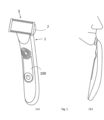
- the cutter system may define a skin contact surface which is inclined at an acute angle relative to the longitudinal axis of the elongated handle of the cutting device so that one side of the skin contact surface slopes down towards a front side of the handle, whereas the opposite side of the skin contact surface essence towards the back side of the handle.
- Said front side of the handle may include, for example, an operation button for switching on and off the drive unit and/or may include a surface contour or portion adapted to a thumb gripping the handle.
- Said skin contact surface of the cutter system may form a sort of monopitch roof attached to one end of the handle.
- the skin contact surface does not have to be flat or planar, wherein, when said skin contact surface is convex and/or concave, a plane tangential to the skin contact surface may have the aforementioned inclination relative to the longitudinal axis of the handle.
- the row of teeth having the more aggressive configuration may be arranged at the lower side of said monopitch roof, i.e. at the side of the skin contact surface sloping down towards the front side of the handle, whereas the row of teeth configured less aggressive may be arranged at the opposite side, i.e. at the upper side of the monopitch roof or the side ascending towards the back side of the handle.
- the skin contact pressure at the sloped down side is lower than the skin contact pressure at the ascending side.
- the more aggressive teeth at the sloped down side having the lower skin contact pressure may achieve efficient hair cutting and catch difficult hair without skin irritations, since the low skin contact pressure is sort of compensating by the increased aggressiveness of the teeth configuration.
- the less aggressive teeth at the opposite, ascending side of the skin contact surface may compensate for the higher skin contact pressure there and to avoid skin irritations.
- the aggressiveness of the teeth may vary also within the same row of cooperating cutting teeth. More particularly, the cutting teeth in a middle section of a row may be different from cutting teeth in end sections of said row in terms of shape and/or size and/or position of the tooth tips so as to provide for a different level of aggressiveness. More particularly, in sections of relatively high skin contact pressure, the teeth may be configured to provide for reduced aggressiveness, whereas the teeth arranged in sections having relatively low skin contact pressure may be configured to provide for a higher level of aggressiveness.
- the skin contact pressure may vary due to the contour of the skin contact surface of the cutter system.
- the skin contact pressure may increase towards the lateral end portions of the skin contact surface.
- Said lateral end portions mean the end portions in the direction of the reciprocating movement of the cutting teeth relative to each other.
- the teeth positioned in the middle section having the lower skin contact pressure may be configured to have a higher aggressiveness what might be achieved by means of a smaller diameter of the rounded tooth tips and/or less curvature away from the skin contact surface.
- the teeth positioned in the end sections having higher skin contact pressure may be configured to provide for reduced aggressiveness what might be achieved by an increased diameter of the rounded tooth tips and/or more curvature away from the skin contact surface.
- the skin contact surface of the cutter system may have a convex contour when viewed in a cross-sectional plane parallel to the direction of reciprocating movement of the cooperating teeth relative to each other and perpendicular to the skin contact surface.
- the skin contact surface of the cutter system may slope down or may be curved away from the skin towards the lateral end portions towards which the teeth reciprocate. Due to such convex contour of the skin contact surface, the skin contact pressure may decrease from the center section of the cutter system towards the end portions thereof. So as to compensate for such varying skin contact pressure, the teeth in the lateral end sections may be configured to have an increased aggressiveness, whereas the teeth in a middle section may be configured less aggressive.
- the configuration of the teeth of a row may change step by step or continuously form the center of the row of teeth to the end portions thereof, wherein said change of the configuration may provide for a distribution of tooth configurations substantially symmetrical with regard to the center of the row of teeth.
- the tooth aggressiveness may change step by step or continuously from the center of a row towards each of the end sections thereof.
- asymmetrical contouring may be provided at the side edges of the skin contact surface of each tooth or at least a group of teeth. More particularly, the teeth which may have a finger-like shape, have skin contact surfaces which may have rounded and/or beveled edges, wherein the degree or level or rounding and/or beveling may vary along the longitudinal axis of the teeth.
- the rounding and/or beveling of the skin contact surface edges may be more pronounced and/or larger at a base section or root section of the teeth than the rounding and/or beveling at a middle section and/or a projecting teeth section close to the tooth tips.
- the skin contact pressure decreases towards the base section or root section of the teeth so the increased rounding and/or beveling of the edges of the skin contact surface of the teeth may allow the skin to sufficiently bulge into the gap between the teeth despite the decreased skin contact pressure.
- an efficient hair cutting and closeness can be achieved over the entire length of the cutting teeth.
- Said rounding and/or beveling of the edges of the skin contact surface of the teeth also may vary along the length of a row of teeth so that in a middle section of the row the rounding and/or beveling of the edges of the skin contact surface of the teeth may be different from the rounding and/or beveling of the skin contact surface of the teeth in end sections of a row of teeth.
- the rounding and/or beveling may be larger and/or more pronounced in sections of the row where the skin contact pressure is lower, whereas the rounding and/or beveling may be smaller and/or less pronounced in sections where the skin contact pressure is higher.
- the overhanging tooth tips may be provided with a two-step rounding including a spherical or drop-shaped or pearl-shaped thickening and a bent or curved portion connecting said thickening to a main portion of the corresponding tooth and bent or curved away from the skin contact surface of said main tooth portion.
- a two-step rounding including a spherical or drop-shaped or pearl-shaped thickening and a bent or curved portion connecting said thickening to a main portion of the corresponding tooth and bent or curved away from the skin contact surface of said main tooth portion.
- Such double-rounded configuration including the rounding of the thickening and the curved or bent configuration of the neighboring tooth portion to which the thickening is attached, may combine closeness and thoroughness of the cutting action with a pleasant skin feel avoiding skin irritations.
- bending the teeth away from the skin contact surface in addition to the provision of a substantially spherical and thus round thickening at the outermost tip portion reliably prevents skin piercing and skin irritations even when the thickening is of a smaller contour which, on the other hand, helps in achieving closeness and thoroughness.
- Said two-step rounding and/or curving may include a concave section between the two rounded portions, more particularly a concave section between the spherical or pearl-shaped thickening and the neighboring curved portion.
- said tangential line contacts said spherical or pearl-shaped thickening on the one hand and the convex curved portion on the other hand, wherein between said two contact points of the imaginative tangential line the aforementioned concave section forms a gap to said tangential line.
- the transitional section between the thickening and the bent or curved portion includes some slack and/or a dint and/or a flattening on the skin contact side of the tooth.
- Said thickening and the bent or curved portion form basically convex skin contact surfaces, whereas the transitional section between said thickening and curved portion form a flattened or concave skin contact surface.
- the substantially spherical thickening may form the very outermost tip portion, wherein the neighboring, more inwardly positioned tip portion may be curved away from the skin contact surface of the main tooth portion. Said more inwardly positioned tip portion is still part of the tooth tip, but is not yet part of the thickening and may have a substantially flat, plate-like configuration with a thickness comparable to or the same as the inner portions or main portion of the cutting tooth.
- Said inner or main portion of the cutting teeth providing for the cutting action due to the other, cooperating teeth closing the gap and passing may have a substantially elongated, plate-like configuration with at least substantially parallel cutting edges formed by longitudinal edges of the tooth body.
- the substantially spherical thickening may be attached forming the tip of the teeth.
- the two-step rounding provides for excellent cutting performance when the cutter system is used in the rake mode as well as in the fork mode.
- the fork mode i.e. the teeth, with their main tooth portion, being substantially parallel to and/or tangential to and/or touching the skin, helps in keeping the skin wave small which skin wave is created when sliding the cutter system along the skin surface. Due to the bending of the tooth tip portion neighboring the thickening away from the skin contact surface, friction between the thickening and the skin can be reduced.
- the substantially spherical thickening guides the pair of cutting elements along the skin surface and achieves a substantially soft cutting procedure.
- each of the cooperating cutting elements may be driven.
- the upper or outer cutting element having the skin contact surface and/or the overhanging tooth tips may be standing and/or may be not reciprocating and not rotating, whereas the lower cutting element which may be the sandwiched cutting element, may reciprocate or rotatorily oscillate.
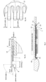
- the cutter system 3 may include elongated rows of cutting teeth 6 and 7 which may reciprocate relative to each other along a linear path so as to effect the cutting action by closing the gaps between the teeth and passing over each other.
- the cutter system 3 also may include cutting teeth 6 and 7 which are aligned along a circle and/or are arranged radially.
- Such rotatory cutting elements 4 and 5 may have cutting teeth 6 and 7 projecting substantially radially, wherein the cutting elements 4 and 5 may be driven to rotate relative to each other and/or to rotatorily oscillate relative to each other.
- the cutting action is basically similar to reciprocating cutting elements as the radially extending teeth, when rotating and/or rotatorily oscillating, cyclically close and reopen the gap between neighboring teeth and pass over each other like a scissor.
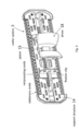
- the sandwiched cutting element 5 may include a recess 19 which may be formed as a throughhole going from one side to the other side of the cutting element 5 and in which said spacer 15 may be received.
- the contour, in particular the inner circumferential contour and/or the edges of said recess 19 may be adapted to the outer contour of the spacer 15 so that the cutting element 5 is guided along the spacer 15 when reciprocating.
- the width of the spacer 15 may substantially correspond to the width of the recess 19 so that the cutting element 5 may slide along the longitudinal side edges of the spacer 15.
- the longitudinal axis of the elongated spacer 15 is coaxial with the reciprocating axis of the cutting element 5, cf. figure 8d .
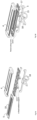
- the support element 17 which may be plate-shaped or formed as a frame extending in a plane, has a size and contour basically comparable to the cutting element 5 to be supported as can be seen from figure 8b , the support element 17 may have a substantially rectangular, plate-like shape supporting the cutting element 5 along lines or strips along the two rows 10 and 11 of cutting teeth 7, whereas the support element 17 may have a size and contour and/or configuration to support also at least a part of the teeth 7 of cutting element 5. In the alternative, the support element 17 may extend at least to the root of the teeth 7.
- the edge of the support element 17 extending along the row of teeth 7, may itself have a wave-shaped or teeth-like configuration with protrusions and gaps therebetween.
- the protrusions 20 extend towards the tips of the teeth 7 at positions where they can support said teeth 7. Due to the toothed configuration of the edge of the support element 17 including the gaps between the protrusions 20, hairs may properly enter into the gaps between the cooperating teeth even when the cutter system is used as a rake. Nevertheless, the protrusions 20 provide for a better support of the teeth 7 against deflection.
- the support element 17 is rigidly held at a predetermined distance from the cutting element 4 so that the gap 16 therebetween has precisely the desired thickness. This is achieved by the aforementioned spacer 15 the thickness of which exactly defines the thickness of gap 16.
- said spacer 15 may have a thickness which is slightly larger than the thickness of the sandwiched cutting element 5, wherein the amount by which the thickness of the spacer 15 exceeds the thickness of the cutting element 5 is smaller than the diameter of usual hair. More particularly, the thickness of the spacer 15 may be larger than the thickness of the sandwiched cutting element 5 by an amount ranging from 20 to 40 ⁇ m.
- the support element 17, the spacer 15 and the cutting element 4 may be rigidly connected to each other, for example by means of snap fitting contours to allow changing the cutting element 4.
- unreleasable fastening is possible, such as welding or glueing.
- the cutting element 4 may be rigidly fixed at the support element 17 at opposite ends thereof, for example by means of end portions 21 which may form lateral protection elements having rounded and/or chamfered contours for soft skin engagement.
- end portions 21 may form lateral protection elements having rounded and/or chamfered contours for soft skin engagement.
- fixation at end portions may be provided in addition or in the alternative to fixation via the spacer 15.
- the support structure 14 also may include a spring device 22 which may urge the cutting element 5 onto the cutting element 4 so as to avoid any gap between the cooperating teeth 6 and 7.
- a spring device 22 may urge the cutting element 5 onto the cutting element 4 so as to avoid any gap between the cooperating teeth 6 and 7.
- Such spring device 21 may be provided between the support structure 14 and the lower or under cutting element 5 so as to press the cutting element 5 onto the cutting element 4.
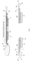
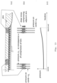
- the teeth 6 of the outer cutting element 4 overlap the cutting teeth 7 of the cooperating cutting element 5, wherein the tooth tips 8 of such overlapping teeth 6 may be provided with substantially spherical thickenings 13, cf. also figure 9 showing such thickenings 13.
- said teeth 6 of the cutting element 4 may be provided with a bent portion 6b connecting said thickening 13 to a main tooth portion 6m which forms the cutting portion of the teeth as such main tooth portion 6m form the blades cooperating with the teeth 7 of the other cutting element 5 in terms of opening and closing the gap between the comb-like, protruding pairs of teeth and passing over each other to achieve shearing of hairs entering into the spaces between the protruding teeth.
- bent portion portion 6b curves away from the skin contact surface 12 of the cutting teeth 6 of cutting element 4, wherein the bent radius R of such bent portion 6b may range from 200 to 400 ⁇ m, for example.
- the bending axis may extend parallel to the reciprocating axis and/or parallel to the longitudinal extension of the row 10, 11 at which the cooperating teeth 6, 7 are arranged.
- the transition portion between the curved portion 6b and the thickening 13 may form a slight depression or a concave portion, as the thickening 13 may further protrude from the bent portion 6m and may have a different radius of curvature r (which is a sphere radius when the thickening is spherically shaped).
- Said bent portion 6b may extend over a bent angle ⁇ ranging from 10° to 45° or 15° to 30° or 10° to 90° or 15° to 180°, cf. figure 5a .
- the substantially spherical thickenings 13 at the tooth tips 8 may have a diameter ranging from 300 to 550 ⁇ m or 350 to 500 ⁇ m.
- a height h including the entire contour of the thickening 13 and the tooth main portion 6m as measured in a direction perpendicular to the skin contact surface 12, may range from 300 to 550 ⁇ m to eliminate the risk of penetration when the cutting system is applied in parallel to the skin as it is shown in figures 4 and 6 .
- the enlargement at the end of the tooth 6 for example in form of a sphere or a drop eliminates the risking case of a perpendicular application as it is shown in figures 7b and 7d .
- the additional bending of the bent portions 6b with the aforementioned bending radius R up to 400 ⁇ m gives an optimal perception of guide with acceptable impact on hair capture.
- the overhang o defining the length of protrusion of the overhanging teeth 6 beyond the teeth 7 of the other cutting element 5, may range from 400 to 800 ⁇ m or 400 to 600 ⁇ m.
- the cutter system is used like a rake as it is shown in figures 7b and 7d , such overhanging length o is helpful to prevent the reciprocating teeth 7 of cutting element 5 from touching and irritating the skin.
- the teeth may have a rather reduced thickness t and/or the thickness t of the teeth 6 and 7 may be adjusted to the gap 22 between pairs of neighboring cutting teeth 6 and 7. Due to the aforementioned described bulging effect of the skin, it may be advantageous to have a teeth thickness t, at a main portion 6m of the teeth 6, ranging from 50 to 150 ⁇ m or 30 to 180 ⁇ m.
- the teeth 7 of the other cutting element 5 may have the same thickness t.
- the gaps 22 between each pair of neighboring cutting teeth 6 and 7 may have a gap width g w ranging from 150 to 550 ⁇ m or 200 to 500 ⁇ m.
- the width tw of the teeth 6 and/or of the teeth 7 may range from 200 to 600 ⁇ m or 250 to 550 ⁇ m. As shown by figure 5b , the width g w of the teeth 6 and 7 may be substantially constant along the longitudinal axis of the teeth. Nevertheless, it would be possible to give the teeth 6 and 7 a slightly V-shaped configuration, wherein the width tw may decrease towards the tips. In such case, the aforementioned width ranges applied to the width tw measured in the middle of the longitudinal extension.
- the skin contact surface of the finger-like teeth 6 have edges 6r which may be rounded and or beveled, wherein such rounding and/or beveling may be more pronounced or may increase towards the root section of the finger-like teeth 6.
- the rounding and/or beveling of the skin contact surface edges may be more pronounced and/or larger at a base section or root section of the teeth 6 than the rounding and/or beveling at a middle section and/or a projecting teeth 6 section close to the tooth tips.
- Said rounding and/or beveling may continuously and/or smoothly increase towards the base section of the teeth 6.
- the skin contact pressure decreases towards the base section or root section of the teeth 6 so the increased rounding and/or beveling of the edges of the skin contact surface of the teeth 6 may allow the skin to sufficiently bulge into the gap between the teeth 6despite the decreased skin contact pressure.
- an efficient hair cutting and closeness can be achieved over the entire length of the cutting teeth 6.
- Said rounding and/or beveling of the edges of the skin contact surface of the teeth 6 also may vary along the length of a row of teeth 6 so that in a middle section of the row the rounding and/or beveling of the edges of the skin contact surface of the teeth 6 may be different from the rounding and/or beveling of the skin contact surface of the teeth 6 in end sections of a row of teeth 6.
- the rounding and/or beveling may be larger and/or more pronounced in sections of the row where the skin contact pressure is lower, whereas the rounding and/or beveling may be smaller in sections where the skin contact pressure is higher.
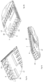
- the cutter system provides for two separate rows 10, 11 of cooperating teeth 6 which are different from each other in terms of shape and/or size and/or positioning of the thickened and/or rounded tooth tips 8 of the teeth 6.
- a first row 10 of cooperating cutting teeth 6 may provide for a more aggressive, closer cutting action
- a second row 11 of cutting teeth 6 may provide for a less intensive, more pleasant skin feel.
- the configuration of the tooth tips 8, in particular the configuration of the curvature and thickening thereof may considerably influence the cutting performance and allow the user to choose between closeness, thoroughness, soft skin feel and efficiency.
- the rows 10, 11 of teeth 6, 7 having different aggressiveness may be positioned on opposite sides of a cutter head 2 and/or may look into opposite directions, i.e. may be open towards opposite directions so as to allow hair to enter into the gaps between the teeth 6 when moving the cutter head 2 into opposite directions.
- the row 11 of teeth 6 having the more aggressive configuration may be arranged at the lower side of said monopitch roof, i.e. at the side of the skin contact surface sloping down towards the front side of the handle 100, whereas the row of teeth 6 configured less aggressive may be arranged at the opposite side, i.e. at the upper side of the monopitch roof or the side ascending towards the back side of the handle 100.
- the skin contact surface is inclined to slope down towards the front side of the handle 100, the skin contact pressure at the sloped down side is lower than the skin contact pressure at the ascending side.
- the configuration of the teeth 6 of a row may change step by step or continuously from the center of the row of teeth 6 to the end portions thereof, wherein said change of the configuration may provide for a distribution of tooth configurations substantially symmetrical with regard to the center of the row of teeth 6.
- the tooth aggressiveness may change step by step or continuously from the center of a row towards each of the end sections thereof, as can be seen from figure 14b .
- the finger-like teeth 6 may be formed from a thin plate-like metal sheet and/or may include substantially plate-shaped tooth bodies, wherein the outer or projecting end portions of the finger-like teeth are bent by more than 90° or more than 100° or more than 120° and/or may form substantially U-shaped end portions, which bent or curved end portions of the finger-like teeth form an outer layer of the tooth tip.
- Such outer layer surrounds an inner layer or filler layer which may fill-out substantially the entire space between the opposite legs of the U-shaped end portions, cf. figure 15 .
- Such filler layer may be a polymeric material or foam material or any other suitable matrix material to fill the space surrounded by the bent end portion.
Landscapes
- Life Sciences & Earth Sciences (AREA)
- Forests & Forestry (AREA)
- Engineering & Computer Science (AREA)
- Mechanical Engineering (AREA)
- Dry Shavers And Clippers (AREA)
Claims (16)
- Schneidemessersystem (3) für einen elektrischen Rasierer und/oder Trimmer (1), umfassend ein Paar von kammartigen Schneidelementen (4, 5), die jeweils zwei Reihen (10, 11) von zusammenwirkenden Schneidzähnen (6, 7) mit einem oberen und einem unteren Schneidelement (4, 5) einschließen, die relativ zueinander bewegbar sind, wobei das obere Schneidelement (4) verdickte und gerundete Zahnspitzen (8) aufweist, die über die Zahnspitzen (9) des unteren Schneidelements (5) hervorragen und in Richtung einer Ebene hervorstehen, in der die Zähne (7) des unteren Schneidelements (5) angeordnet sind,
dadurch gekennzeichnet, dass sich die Reihen (10, 11) des oberen Schneidelements (4) von Schneidzähnen (6) hinsichtlich der Form und/oder Größe und/oder Position der hervorragenden, verdickten und gerundeten Zahnspitzen (8) voneinander unterscheiden und wobei die hervorragenden Zahnspitzen (8) an einer anderen Reihe (10) von Schneidzähnen (6) weiter von der Hautkontaktfläche des Hauptabschnitts (6m) der Schneidzähne (6) entfernt als die hervorragenden Zahnspitzen (8) einer Reihe (11) von Schneidzähnen (6) angeordnet sind. - Schneidemessersystem nach dem vorstehenden Anspruch, wobei an einer Reihe von Schneidzähnen die hervorragenden Zahnspitzen (8) nur zu der Seite entgegengesetzt der Hautkontaktfläche (12) hervorstehen, während an der anderen Reihe (11) von Schneidzähnen (6) die hervorragenden Zahnspitzen (8) zu der Hautkontaktflächenseite und zu der Seite entgegengesetzt der Hautkontaktfläche (12) hervorstehen.
- Schneidemessersystem nach einem der vorstehenden Ansprüche, wobei die hervorragenden Zahnspitzen (8) an einer Reihe (10) von Schneidzähnen (6) aufweisen- eine Höhe (h), gemessen in der Richtung lotrecht zu der Hautkontaktfläche (12), in einem Bereich von 350-550 µm und/oder- eine kugel- oder tropfenförmige oder perlenförmige Verdickung (11) mit einem Durchmesser (2r) in einem Bereich von 350-550 µm,wobei die hervorragenden Zahnspitzen (8) an der anderen Reihe (11) von Schneidzähnen (6) aufweisen- eine Höhe (h), gemessen in der Richtung lotrecht zu der Hautkontaktfläche (12), in einem Bereich von 250-450 µm und/oder- kugel- oder tropfenförmige oder perlenförmige Verdickungen (13) mit einem Durchmesser in einem Bereich von 250-450 µm.
- Schneidemessersystem nach einem der vorstehenden Ansprüche, wobei die zwei Reihen (10, 11) von zusammenwirkenden Schneidzähnen (6, 7) an entgegengesetzten Seiten eines Schneidemesserkopfes (2) eingerichtet sind, der eine Hautkontaktfläche definiert und an einem länglichen Griff (100) an einem Ende davon befestigt ist, wobei die Hautkontaktfläche in einem spitzen Winkel schräg ist, um in Richtung einer Vorderseite des Griffs (100) abzufallen und in Richtung einer Rückseite des Griffs (100) anzusteigen, wobei die Reihe (11) von zusammenwirkenden Zähne (6, 7) an der abfallenden Vorderseite eine aggressivere Zahnspitzenkonfiguration aufweist, insbesondere Zahnspitzen mit einem geringeren Durchmesser und/oder einer geringeren Höhe und/oder näher an der Hautkontaktfläche angeordnet, als die andere Reihe (10) von zusammenwirkenden Zähnen (6, 7) an der ansteigenden Rückseite des Schneidemesserkopfes (2).
- Schneidemessersystem nach einem der vorstehenden Ansprüche, wobei wenigstens eine Reihe (10, 11) von zusammenwirkenden Schneidzähnen (6, 7) Schneidzähne (6) unterschiedlicher Konfiguration einschließt, wobei sich Schneidzähne (6) in einem Mittelbereich der Reihe (10, 11) hinsichtlich der Form und/oder Größe und/oder Position der Zahnspitzen (8) von Schneidzähnen (6) in Endbereichen der Reihe (10, 11) unterscheiden.
- Schneidemessersystem nach dem vorstehenden Anspruch, wobei die Konfiguration der Zähne 6 schrittweise oder ununterbrochen von dem Mittelbereich zu jedem der Endbereiche hin wechselt, sodass eine Verteilung von Zahnkonfigurationen bezüglich des Mittelbereichs symmetrisch ist und eine Zahnaggressivität schrittweise oder ununterbrochen von dem Mittelbereich zu jedem der Endbereiche hin wechselt.
- Schneidemessersystem nach Anspruch 5 oder 6, wobei die Reihe (10, 11) von zusammenwirkenden Zähnen (6, 7) eine Hautkontaktfläche definiert, die unterschiedlichen Hautkontaktdruck in unterschiedlichen Bereichen der Hautkontaktfläche erzeugt, wobei die Zahnspitzen in Hautkontaktflächenbereichen eines höheren Hautkontaktdrucks weniger aggressiv konfiguriert sind als Zahnspitzen in Hautkontaktflächenbereichen, die einen niedrigeren Hautkontaktdruck erzeugen.
- Schneidemessersystem nach einem der vorstehenden Ansprüche, wobei wenigstens eine Reihe (10, 11) von zusammenwirkenden Schneidzähnen (6, 7) eine konvexe oder konkave Hautkontaktfläche definiert, wenn sie in einer Querschnittsebene parallel zu einer Hin- und Herbewegungsrichtung der Schneidzähne (6, 7) und lotrecht zu der Hautkontaktfläche betrachtet wird.
- Schneidemessersystem nach dem vorstehenden Anspruch, wobei für eine konvexe Hautkontaktfläche die Zahnspitzen der Zähne (6) konfiguriert sind, um von einem Mittelbereich zu jedem der Endbereiche der Reihe (10, 11) oder zusammenwirkenden Zähne (6, 7) hin stufenweise oder ununterbrochen aggressiver zu werden.
- Schneidemessersystem nach einem der vorstehenden Ansprüche, wobei die Schneidzähne (6) Hautkontaktflächen mit gerundeten und/oder abgeschrägten Kanten (6R) aufweisen, wobei die Rundung und/oder Abschrägung der Kanten der Hautkontaktflächen der Zähne (6) entlang einer Zahnlängsachse (6L) variiert.
- Schneidemessersystem nach dem vorstehenden Anspruch, wobei die Rundung und/oder Abschrägung der Kanten der Hautkontaktfläche der Zähne (6) zu einem Wurzelbereich der Zähne (6) hin schrittweise oder ununterbrochen zunimmt.
- Schneidemessersystem nach einem der zwei vorstehenden Ansprüche, wobei die wenigstens eine Reihe (10, 11) von zusammenwirkenden Zähnen (6, 7) Schneidzähne (6) mit variierenden gerundeten und/oder abgeschrägten Kanten einschließt, wobei sich die Rundung und/oder Abschrägung der Kanten der Hautkontaktoberfläche der Zähne (6) in einem Mittelbereich der Reihe (10, 11) von zusammenwirkenden Zähnen (6, 7) von der Rundung und/oder Abschrägung der Kanten der Hautkontaktoberfläche der Zähne (6) in Endbereichen der Reihe (10, 11) von zusammenwirkenden Zähnen (6, 7) unterscheidet.
- Schneidemessersystem nach einem der vorstehenden Ansprüche, wobei die Schneidzähne (6, 7), an einem Hauptzahnabschnitt (6m), der eine Schneidaktion bereitstellt, eine Zahnbreite (wt) in einem Bereich von 250-550 µm und eine Dicke (t) in einem Bereich von 50-150 µm aufweisen.
- Schneidemessersystem nach einem der vorstehenden Ansprüche, wobei die Schneidzähne (6) eine Zahnhöhe (h) aufweisen, die die gerundeten, verdickten Zahnspritzen (8) aufweisen, die in einem Bereich von 250-550 µm liegen, und einen Spalt zwischen benachbarten Schneidzähnen definieren, der eine Spaltbreite (wg) in einem Bereich von 200-500 µm aufweist, wobei die Spaltbreite an der Mitte der Länge der Zähne (6) gemessen wird.
- Schneidemessersystem nach Anspruch 1, wobei die Schneidzähne (6) von unterschiedlichen Reihen (10, 11) von zusammenwirkenden Schneidzähnen (6, 7) Hautkontaktflächen (13) aufweisen, die koplanar sind.
- Elektrischer Rasierer und/oder Trimmer, umfassend ein Schneidemessersystem, das nach einem der vorstehenden Ansprüche konfiguriert ist.
Priority Applications (12)
| Application Number | Priority Date | Filing Date | Title |
|---|---|---|---|
| EP20153379.1A EP3854540B1 (de) | 2020-01-23 | 2020-01-23 | Elektrischer bartschneider |
| EP21701187.3A EP4093583B1 (de) | 2020-01-23 | 2021-01-25 | Elektrischer bartschneider |
| JP2022545021A JP7564221B2 (ja) | 2020-01-23 | 2021-01-25 | 電気髭トリマー |
| US17/157,858 US11731294B2 (en) | 2020-01-23 | 2021-01-25 | Electric beard trimmer |
| JP2022545020A JP7564220B2 (ja) | 2020-01-23 | 2021-01-25 | 電気髭トリマー |
| PCT/IB2021/050553 WO2021149027A1 (en) | 2020-01-23 | 2021-01-25 | Electric beard trimmer |
| PCT/IB2021/050552 WO2021149026A1 (en) | 2020-01-23 | 2021-01-25 | Electric beard trimmer |
| CN202180010483.1A CN115003475B (zh) | 2020-01-23 | 2021-01-25 | 电动胡须修剪器 |
| CN202180010482.7A CN115003474B (zh) | 2020-01-23 | 2021-01-25 | 电动胡须修剪器 |
| GB2210122.4A GB2607204A (en) | 2020-01-23 | 2021-01-25 | Electric beard trimmer |
| US17/157,862 US12384063B2 (en) | 2020-01-23 | 2021-01-25 | Electric beard trimmer |
| GB2210144.8A GB2607207A (en) | 2020-01-23 | 2021-01-25 | Electric beard trimmer |
Applications Claiming Priority (1)
| Application Number | Priority Date | Filing Date | Title |
|---|---|---|---|
| EP20153379.1A EP3854540B1 (de) | 2020-01-23 | 2020-01-23 | Elektrischer bartschneider |
Publications (2)
| Publication Number | Publication Date |
|---|---|
| EP3854540A1 EP3854540A1 (de) | 2021-07-28 |
| EP3854540B1 true EP3854540B1 (de) | 2025-03-19 |
Family
ID=69190683
Family Applications (2)
| Application Number | Title | Priority Date | Filing Date |
|---|---|---|---|
| EP20153379.1A Active EP3854540B1 (de) | 2020-01-23 | 2020-01-23 | Elektrischer bartschneider |
| EP21701187.3A Active EP4093583B1 (de) | 2020-01-23 | 2021-01-25 | Elektrischer bartschneider |
Family Applications After (1)
| Application Number | Title | Priority Date | Filing Date |
|---|---|---|---|
| EP21701187.3A Active EP4093583B1 (de) | 2020-01-23 | 2021-01-25 | Elektrischer bartschneider |
Country Status (6)
| Country | Link |
|---|---|
| US (2) | US12384063B2 (de) |
| EP (2) | EP3854540B1 (de) |
| JP (2) | JP7564220B2 (de) |
| CN (2) | CN115003474B (de) |
| GB (2) | GB2607204A (de) |
| WO (2) | WO2021149027A1 (de) |
Families Citing this family (9)
| Publication number | Priority date | Publication date | Assignee | Title |
|---|---|---|---|---|
| EP3854542B1 (de) | 2020-01-23 | 2023-12-13 | Braun GmbH | Elektrischer bartschneider |
| EP3854540B1 (de) * | 2020-01-23 | 2025-03-19 | Braun GmbH | Elektrischer bartschneider |
| EP3854538B1 (de) * | 2020-01-23 | 2024-10-16 | Braun GmbH | Elektrischer bartschneider |
| EP3854541B1 (de) | 2020-01-23 | 2024-06-26 | Braun GmbH | Elektrischer bartschneider |
| USD1041752S1 (en) * | 2020-05-08 | 2024-09-10 | Braun Gmbh | Hair removal device |
| WO2023043629A1 (en) * | 2021-09-14 | 2023-03-23 | Wahl Clipper Corporation | Hair clipper bladeset with variable rake angle array tooth geometry |
| USD999986S1 (en) * | 2022-11-22 | 2023-09-26 | Yiwu Waha Home Appliance Co., Ltd. | Hair trimmer |
| USD999984S1 (en) * | 2022-11-22 | 2023-09-26 | Yiwu Waha Home Appliance Co., Ltd. | Hair trimmer |
| USD1058045S1 (en) * | 2024-04-11 | 2025-01-14 | Yunxia ZHANG | Razor blade head |
Citations (1)
| Publication number | Priority date | Publication date | Assignee | Title |
|---|---|---|---|---|
| US3279056A (en) * | 1964-10-28 | 1966-10-18 | Andis Clipper Co | Double-edge combination dry shaver and finishing hair clipper with adjustable head |
Family Cites Families (128)
| Publication number | Priority date | Publication date | Assignee | Title |
|---|---|---|---|---|
| US1567110A (en) * | 1925-04-09 | 1925-12-29 | Franciss G W Bristow | Sheep shear |
| US1875125A (en) * | 1929-07-29 | 1932-08-30 | Oster John Mfg Co | Hand operated hair clipper |
| CH160230A (de) * | 1932-03-31 | 1933-02-28 | Brunner Walter | Gezahnte Klinge für Trockenrasiermaschinen. |
| DE622922C (de) | 1932-03-31 | 1935-12-09 | Walter Brunner | Haarschermaschine |
| US2249825A (en) | 1935-03-07 | 1941-07-22 | Gillette Safety Razor Co | Hair clipper |
| US2273739A (en) | 1939-01-09 | 1942-02-17 | Pas Coletta A Te | Shaving device and cutter head therefor |
| US2246586A (en) | 1939-11-09 | 1941-06-24 | Gillette Safety Razor Co | Dry shaving cutter mount |
| US2713718A (en) * | 1954-03-24 | 1955-07-26 | Alexander Healy Jr | Clipper combs |
| US2859513A (en) * | 1956-06-28 | 1958-11-11 | Schick Inc | Electric shaver shearing head assembly |
| NL289315A (de) * | 1963-02-21 | |||
| AU440711B2 (en) | 1966-09-21 | 1973-09-19 | Basil Leigh Jenkinson Mervyn | Sheepshearing handpiece with reciprocating pneumatic motor |
| DE2050539C3 (de) | 1970-10-15 | 1979-10-18 | Drees & Co, Gmbh, 4760 Werl | Falzmaschine für Leder u.dgl |
| US3672049A (en) | 1970-10-22 | 1972-06-27 | Sperry Rand Corp | Hair trimmer attachment for electric shavers |
| JPS5030989U (de) * | 1973-07-13 | 1975-04-05 | ||
| JPS5244360B2 (de) | 1973-07-18 | 1977-11-07 | ||
| NL7409107A (nl) | 1974-07-05 | 1976-01-07 | Philips Nv | Werkwijze en inrichting voor het inslijpen van groeven. |
| JPS5128293U (de) * | 1974-08-23 | 1976-03-01 | ||
| JPS5492455A (en) * | 1977-12-28 | 1979-07-21 | Matsushita Electric Works Ltd | Reciprocating electric razor |
| DE3128563A1 (de) * | 1981-07-18 | 1983-02-03 | MDS Mannesmann Demag Sack GmbH, 4000 Düsseldorf | Hartmetallbestueckter abwaelzfraeser, sogenannter schaelwaelzfraeser |
| JPS59501246A (ja) | 1982-07-15 | 1984-07-19 | ツアボ、シユテフアン・エル | バリカン |
| DE3610736A1 (de) | 1986-03-29 | 1987-10-01 | Braun Ag | Elektrischer rasierapparat mit einem schwenkbaren scherkopfsystem |
| NL8700516A (nl) | 1987-03-04 | 1988-10-03 | Philips Nv | Knipeenheid. |
| CN1016855B (zh) * | 1988-01-22 | 1992-06-03 | 重庆大学 | 新型磨削剃齿刀砂轮的修形装置及其修形方法 |
| EP0652085A1 (de) * | 1993-11-10 | 1995-05-10 | Koninklijke Philips Electronics N.V. | Gerät zum Schneiden von Haaren mit einer Zahnschneideinrichtung |
| AT401901B (de) | 1993-11-10 | 1996-12-27 | Philips Electronics Nv | Gerät zum schneiden von haaren mit einer zahnschneideinrichtung und verfahren zum herstellen eines messers für eine zahnschneideinrichtung eines solchen gerätes |
| EP0840671A1 (de) * | 1996-04-26 | 1998-05-13 | Koninklijke Philips Electronics N.V. | Haarschneideapparat mit einem gezahnten schneidevorsatz und gezahnte schneidevorrrichtung für einen solchen apparat |
| WO2000058060A1 (en) | 1999-03-28 | 2000-10-05 | Barish Benjamin J | Electrical hair remover device and method |
| JP2002537918A (ja) | 1999-03-01 | 2002-11-12 | コーニンクレッカ フィリップス エレクトロニクス エヌ ヴィ | 歯の端部が湾曲した毛捕捉歯を有する歯付きカッタ |
| US6530150B1 (en) | 1999-05-17 | 2003-03-11 | Benjamin J. Barish | Attachments for electrical shaver and auxiliary cleaning device useful for electrical shaver |
| US6317982B1 (en) | 1999-10-22 | 2001-11-20 | Remington Corporation L.L.C. | Shaving system and adjustable trimmers therefor |
| US6658740B2 (en) | 2001-03-16 | 2003-12-09 | Wahl Clipper Corporation | Blade assembly for a vibrator motor |
| ATE309892T1 (de) | 2001-08-10 | 2005-12-15 | Matsushita Electric Works Ltd | Innere rasierklingeneinheit für elektrischen rasierapparat |
| JP4479988B2 (ja) | 2003-08-07 | 2010-06-09 | 九州日立マクセル株式会社 | 電気かみそり |
| DE10344566A1 (de) | 2003-09-25 | 2005-04-28 | Braun Gmbh | Schersystem für ein elektrisches Haarentfernungsgerät |
| JP5051681B2 (ja) | 2005-02-23 | 2012-10-17 | 日立マクセル株式会社 | 電気かみそり |
| JP4824967B2 (ja) | 2005-08-10 | 2011-11-30 | パナソニック電工株式会社 | 電気かみそり用アタッチメント |
| DE202006007059U1 (de) | 2005-12-12 | 2006-10-12 | Koninklijke Philips Electronics N.V. | Schneideeinheit mit Schutzzähnen und Haarschneidevorrichtung |
| US8479400B2 (en) | 2006-08-31 | 2013-07-09 | Panasonic Corporation | Hair clipper |
| JP4207080B2 (ja) | 2006-12-08 | 2009-01-14 | パナソニック電工株式会社 | 電気かみそり |
| DE102007005853A1 (de) | 2007-02-01 | 2008-08-07 | Braun Gmbh | Haarentfernungsgerät |
| DE102007023362A1 (de) * | 2007-05-18 | 2008-11-20 | Braun Gmbh | Schneideinrichtung zum Schneiden von Haaren |
| WO2009024900A1 (en) | 2007-08-17 | 2009-02-26 | Koninklijke Philips Electronics N.V. | Hair trimming device |
| DE102007050379A1 (de) | 2007-10-22 | 2009-04-23 | Braun Gmbh | Haartrimmer |
| US20090119932A1 (en) * | 2007-11-10 | 2009-05-14 | Specialife Industries Limited | Curved and toothed cutting blade for a trimmer and a grinding wheel for manufacturing therefor |
| EP2085194A1 (de) | 2008-01-29 | 2009-08-05 | Braun GmbH | Schneidekamm, Haarschneidegerät mit einem Schneidekamm und Herstellungsverfahren für einen Schneidekamm |
| ATE532613T1 (de) | 2008-01-29 | 2011-11-15 | Braun Gmbh | Schneidekamm, haarschneidegerät mit einem schneidekamm und herstellungsverfahren für einen schneidekamm |
| DE202008002467U1 (de) * | 2008-02-21 | 2008-04-30 | Wahl Gmbh | Schneidsatz für elektrische Haarschneidemaschinen |
| US9302401B2 (en) | 2009-01-27 | 2016-04-05 | Braun Gmbh | Trimmer comb, hair trimmer comprising a trimmer comb and method of manufacturing a trimmer comb |
| CN201361884Y (zh) | 2009-02-11 | 2009-12-16 | 浙江金达电机电器有限公司 | 旋转式电动剃须刀双层刀头 |
| US20110010941A1 (en) * | 2009-07-20 | 2011-01-20 | Specialife Industries Limited | Nose hair trimmer with dual cutting edges |
| JP5473462B2 (ja) * | 2009-08-06 | 2014-04-16 | 株式会社泉精器製作所 | ロータリー式電気かみそり |
| CN201471463U (zh) | 2009-08-27 | 2010-05-19 | 张大 | 一种动静刀头自紧型电推剪 |
| WO2011070550A1 (en) | 2009-12-10 | 2011-06-16 | Braun Gmbh | Toothbrush |
| EP2425938B1 (de) * | 2010-09-03 | 2014-02-26 | Braun GmbH | Rasierkopf mit mehreren Rasiereinheiten |
| USD672923S1 (en) * | 2010-10-15 | 2012-12-18 | United Pet Group, Inc. | Convex grooming tool blade |
| USD672924S1 (en) | 2010-10-15 | 2012-12-18 | United Pet Group, Inc. | Concave grooming tool blade |
| BRPI1101269A2 (pt) | 2011-03-14 | 2015-07-28 | Claudio Takashi Oda | Máquina de cortar e aspirar cabelo |
| CN102328321B (zh) | 2011-09-28 | 2014-03-12 | 宁波真和电器股份有限公司 | 多刀片电动剃须刀的刀头结构 |
| WO2013072840A1 (en) | 2011-11-17 | 2013-05-23 | Koninklijke Philips Electronics N.V. | Skin guard for hair trimmer |
| CN102553474B (zh) | 2011-12-30 | 2014-07-23 | 上海新拓分析仪器科技有限公司 | 一种搅拌剪切工具 |
| AU2013245349B2 (en) | 2012-04-03 | 2017-04-27 | Koninklijke Philips N.V. | Blade set for hair cutting appliance and method for its manufacture |
| CN102744736B (zh) | 2012-07-26 | 2014-11-12 | 珠海新秀丽家居用品有限公司 | 双刀体毛修剪器 |
| WO2014191867A1 (en) | 2013-05-30 | 2014-12-04 | Koninklijke Philips N.V. | Stationary cutting blade for a hair clipping device |
| GB2517938A (en) * | 2013-09-05 | 2015-03-11 | Heiniger Ltd | A shearing comb |
| CN103468914B (zh) * | 2013-09-17 | 2015-01-21 | 蓬溪河冶高科有限责任公司 | 剃齿刀热处理工艺 |
| EP2857158B1 (de) | 2013-10-01 | 2017-05-10 | Koninklijke Philips N.V. | Klingensatz und Haarschneidegerät |
| EP2857154B1 (de) | 2013-10-01 | 2019-02-20 | Koninklijke Philips N.V. | Klingensatz und Haarschneideanwendung |
| EP2857155A1 (de) | 2013-10-01 | 2015-04-08 | Koninklijke Philips N.V. | Klingensatz und Haarschneidegerät |
| EP2857157B1 (de) | 2013-10-01 | 2017-12-13 | Koninklijke Philips N.V. | Klingensatz, Haarschneidegerät und zugehöriges Herstellungsverfahren |
| EP2857156B1 (de) | 2013-10-01 | 2019-01-16 | Koninklijke Philips N.V. | Klingensatz und Haarschneidegerät |
| EP2875917A1 (de) | 2013-11-22 | 2015-05-27 | Koninklijke Philips N.V. | Haarschneidegerät und Klingensatz |
| WO2015103248A1 (en) | 2014-01-01 | 2015-07-09 | Daniel Lawrence Roth | Shaving and grooming apparatus |
| EP3131714B1 (de) | 2014-04-18 | 2018-06-13 | Koninklijke Philips N.V. | Klingensatz, haarschneideanwendung und zugehöriges herstellungsverfahren |
| WO2015158571A1 (en) | 2014-04-18 | 2015-10-22 | Koninklijke Philips N.V. | Blade set, hair cutting appliance, and related manufacturing method |
| WO2015158923A1 (en) | 2014-04-18 | 2015-10-22 | Koninklijke Philips N.V. | Blade set, hair cutting appliance, and related manufacturing method |
| CN203765658U (zh) | 2014-04-23 | 2014-08-13 | 邱锦辉 | 一种多功能理发器 |
| US20150314461A1 (en) | 2014-05-02 | 2015-11-05 | Raymond Industrial Ltd. | Hybrid Shaving System |
| WO2016001019A1 (en) | 2014-07-04 | 2016-01-07 | Koninklijke Philips N.V. | Blade set, hair cutting appliance, and related manufacturing method |
| CN105437268B (zh) * | 2014-09-18 | 2019-03-08 | 皇家飞利浦有限公司 | 刀片组,剪发器具,以及相关的制造方法 |
| EP3131711B1 (de) | 2014-09-18 | 2018-03-21 | Koninklijke Philips N.V. | Schneidkopf und haarschneidegerät |
| WO2016041796A1 (en) | 2014-09-18 | 2016-03-24 | Koninklijke Philips N.V. | Blade set, cutting appliance, and related manufacturing method |
| EP3253541B1 (de) | 2015-02-04 | 2018-06-20 | Koninklijke Philips N.V. | Schneidkopf und haarschneidegerät |
| EP3261810B1 (de) | 2015-02-25 | 2020-04-08 | Koninklijke Philips N.V. | Stationäre klinge, klingensatz und haarschneidegerät |
| CN107666992B (zh) | 2015-04-28 | 2020-06-05 | 皇家飞利浦有限公司 | 刀片组和毛发切割器具 |
| EP3090844A1 (de) | 2015-05-08 | 2016-11-09 | Braun GmbH | Verfahren zur anpassung der maximalen kühltemperatur eines kühlelements eines elektrischen benutzergeräts sowie elektrisches benutzergerät |
| EP3297797B1 (de) | 2015-05-19 | 2020-04-29 | Koninklijke Philips N.V. | Verfahren zur herstellung einer stationären schaufel sowie stationäre schaufel |
| CN104999486A (zh) | 2015-06-24 | 2015-10-28 | 李洁梅 | 一种旋转式剃须刀刀头装置 |
| CN104999485B (zh) | 2015-08-20 | 2019-07-23 | 珠海新秀丽家居用品有限公司 | 具有超薄定刀的新型个人护理修剪器 |
| GB2542124B (en) * | 2015-09-08 | 2019-06-05 | Technicut Ltd | Method and tools for manufacturing a bladed disk |
| JP6629600B2 (ja) | 2016-01-18 | 2020-01-15 | マクセルホールディングス株式会社 | 電気かみそり |
| CN206105917U (zh) | 2016-08-11 | 2017-04-19 | 王小明 | 一种电推剪定刀片及刀头 |
| EP3300847B1 (de) | 2016-09-28 | 2019-10-30 | Braun GmbH | Bartschneider |
| EP3300859B1 (de) | 2016-09-28 | 2021-09-01 | Braun GmbH | Bartschneider |
| EP3300858B1 (de) | 2016-09-28 | 2021-04-07 | Braun GmbH | Bartschneider |
| CN106346519B (zh) | 2016-10-12 | 2019-12-17 | 中山市小石陶瓷刀片有限公司 | 一种往复式电动剃毛刀头 |
| CN206287174U (zh) | 2016-11-17 | 2017-06-30 | 王小明 | 一种剃须刀头以及剃须刀 |
| MX2019008747A (es) | 2017-01-27 | 2019-09-11 | Koninklijke Philips Nv | Unidad de afeitar con husillos de accionamiento que se extienden en el espacio abierto. |
| EP4032668B1 (de) | 2017-02-27 | 2025-05-28 | Spectrum Brands, Inc. | Elektrische handhaarschneidemaschine mit klingenschutz |
| EP3381629A1 (de) * | 2017-03-28 | 2018-10-03 | Koninklijke Philips N.V. | Kammanordnung, schneidkopf und haarschneidegerät |
| CN206633052U (zh) | 2017-04-01 | 2017-11-14 | 吴让攀 | 一种电动剃毛刀头 |
| EP3388207A1 (de) | 2017-04-10 | 2018-10-17 | Koninklijke Philips N.V. | Stationäre klinge, klingensatz und haarschneidegerät |
| EP3388209A1 (de) | 2017-04-11 | 2018-10-17 | Koninklijke Philips N.V. | Stationäre klinge, klingensatz und herstellungsverfahren |
| EP3388206A1 (de) | 2017-04-14 | 2018-10-17 | Koninklijke Philips N.V. | Aufsteckkamm, schneidkopf und haarschneidegerät |
| CN208342890U (zh) | 2017-05-15 | 2019-01-08 | A·库班尼 | 毛发修剪装置 |
| EP3403779A1 (de) | 2017-05-15 | 2018-11-21 | Koninklijke Philips N.V. | Abstandskamm und haarschneidegerät |
| EP3409432A1 (de) | 2017-05-30 | 2018-12-05 | Koninklijke Philips N.V. | Stationäre klinge, klingensatz und herstellungsverfahren |
| EP3415288A1 (de) * | 2017-06-14 | 2018-12-19 | Koninklijke Philips N.V. | Haarschneidesystem und anbauteil |
| CN207139864U (zh) | 2017-09-12 | 2018-03-27 | 浙江美森电器有限公司 | 无锐口刀片及理发剪 |
| CN107639657A (zh) | 2017-09-12 | 2018-01-30 | 浙江美森电器有限公司 | 无锐口刀片及理发剪 |
| EP3461602A1 (de) | 2017-10-02 | 2019-04-03 | Koninklijke Philips N.V. | Stationäre schaufel und herstellungsverfahren |
| EP3466619A1 (de) | 2017-10-05 | 2019-04-10 | Koninklijke Philips N.V. | Schaufelsatz und herstellungsverfahren |
| RU2760866C1 (ru) | 2017-12-05 | 2021-12-01 | Конинклейке Филипс Н.В. | Бритвенный блок и устройство для срезания волос |
| EP3768476B1 (de) | 2018-03-23 | 2021-11-17 | Koninklijke Philips N.V. | Rasieranordnung und haarschneidegerät |
| CN209364682U (zh) | 2018-11-09 | 2019-09-10 | 海宁市永发刀剪有限公司 | 一种无锐口安全刀片 |
| CN110091364A (zh) | 2019-04-22 | 2019-08-06 | 浙江朗威电器科技有限公司 | 一种毛发切割器具、切割单元、静刀结构及静刀结构的加工工艺 |
| JP7562070B2 (ja) | 2019-06-19 | 2024-10-07 | ベクトン・ディキンソン・アンド・カンパニー | 治療剤の送達のための生分解性薬物溶出塞栓粒子 |
| CN110562534A (zh) | 2019-09-29 | 2019-12-13 | 深圳市瑞飞科技有限公司 | 粉料包装机 |
| EP3854541B1 (de) | 2020-01-23 | 2024-06-26 | Braun GmbH | Elektrischer bartschneider |
| EP3854538B1 (de) | 2020-01-23 | 2024-10-16 | Braun GmbH | Elektrischer bartschneider |
| EP3854542B1 (de) | 2020-01-23 | 2023-12-13 | Braun GmbH | Elektrischer bartschneider |
| EP3854540B1 (de) * | 2020-01-23 | 2025-03-19 | Braun GmbH | Elektrischer bartschneider |
| BR112022004700A2 (pt) | 2020-02-28 | 2022-10-18 | Lg Chemical Ltd | Dispositivo de corte de hidrogel de polímero superabsorvente |
| EP3900896B1 (de) | 2020-04-24 | 2022-08-17 | Wahl GmbH | Schneidsatz mit wellenförmiger schneidkante |
| EP3907048B1 (de) | 2020-05-08 | 2023-03-22 | Braun GmbH | Elektrischer bartschneider |
| EP3907047B1 (de) | 2020-05-08 | 2025-04-16 | Braun GmbH | Elektrischer bartschneider |
| EP3907049B1 (de) | 2020-05-08 | 2023-03-22 | Braun GmbH | Elektrischer bartschneider |
| EP3907044B1 (de) | 2020-05-08 | 2024-10-16 | Braun GmbH | Elektrischer bartschneider |
| EP4119312B1 (de) | 2021-07-15 | 2025-03-19 | Braun GmbH | Schneidsystem für einen elektrischen barttrimmer |
-
2020
- 2020-01-23 EP EP20153379.1A patent/EP3854540B1/de active Active
-
2021
- 2021-01-25 US US17/157,862 patent/US12384063B2/en active Active
- 2021-01-25 GB GB2210122.4A patent/GB2607204A/en not_active Withdrawn
- 2021-01-25 CN CN202180010482.7A patent/CN115003474B/zh active Active
- 2021-01-25 CN CN202180010483.1A patent/CN115003475B/zh active Active
- 2021-01-25 JP JP2022545020A patent/JP7564220B2/ja active Active
- 2021-01-25 WO PCT/IB2021/050553 patent/WO2021149027A1/en not_active Ceased
- 2021-01-25 GB GB2210144.8A patent/GB2607207A/en not_active Withdrawn
- 2021-01-25 US US17/157,858 patent/US11731294B2/en active Active
- 2021-01-25 JP JP2022545021A patent/JP7564221B2/ja active Active
- 2021-01-25 WO PCT/IB2021/050552 patent/WO2021149026A1/en not_active Ceased
- 2021-01-25 EP EP21701187.3A patent/EP4093583B1/de active Active
Patent Citations (1)
| Publication number | Priority date | Publication date | Assignee | Title |
|---|---|---|---|---|
| US3279056A (en) * | 1964-10-28 | 1966-10-18 | Andis Clipper Co | Double-edge combination dry shaver and finishing hair clipper with adjustable head |
Also Published As
| Publication number | Publication date |
|---|---|
| US20210229300A1 (en) | 2021-07-29 |
| JP7564221B2 (ja) | 2024-10-08 |
| US11731294B2 (en) | 2023-08-22 |
| WO2021149026A1 (en) | 2021-07-29 |
| JP2023511594A (ja) | 2023-03-20 |
| GB202210122D0 (en) | 2022-08-24 |
| EP3854540A1 (de) | 2021-07-28 |
| EP4093583B1 (de) | 2025-01-22 |
| EP4093583A1 (de) | 2022-11-30 |
| CN115003474B (zh) | 2024-03-29 |
| GB2607204A (en) | 2022-11-30 |
| US20210229301A1 (en) | 2021-07-29 |
| JP7564220B2 (ja) | 2024-10-08 |
| CN115003474A (zh) | 2022-09-02 |
| CN115003475A (zh) | 2022-09-02 |
| CN115003475B (zh) | 2024-06-25 |
| GB202210144D0 (en) | 2022-08-24 |
| GB2607207A (en) | 2022-11-30 |
| US12384063B2 (en) | 2025-08-12 |
| WO2021149027A1 (en) | 2021-07-29 |
| JP2023511593A (ja) | 2023-03-20 |
Similar Documents
| Publication | Publication Date | Title |
|---|---|---|
| EP3854540B1 (de) | Elektrischer bartschneider | |
| EP3854541B1 (de) | Elektrischer bartschneider | |
| EP3854542B1 (de) | Elektrischer bartschneider |
Legal Events
| Date | Code | Title | Description |
|---|---|---|---|
| PUAI | Public reference made under article 153(3) epc to a published international application that has entered the european phase |
Free format text: ORIGINAL CODE: 0009012 |
|
| STAA | Information on the status of an ep patent application or granted ep patent |
Free format text: STATUS: THE APPLICATION HAS BEEN PUBLISHED |
|
| AK | Designated contracting states |
Kind code of ref document: A1 Designated state(s): AL AT BE BG CH CY CZ DE DK EE ES FI FR GB GR HR HU IE IS IT LI LT LU LV MC MK MT NL NO PL PT RO RS SE SI SK SM TR |
|
| STAA | Information on the status of an ep patent application or granted ep patent |
Free format text: STATUS: REQUEST FOR EXAMINATION WAS MADE |
|
| 17P | Request for examination filed |
Effective date: 20220127 |
|
| RBV | Designated contracting states (corrected) |
Designated state(s): AL AT BE BG CH CY CZ DE DK EE ES FI FR GB GR HR HU IE IS IT LI LT LU LV MC MK MT NL NO PL PT RO RS SE SI SK SM TR |
|
| P01 | Opt-out of the competence of the unified patent court (upc) registered |
Effective date: 20230430 |
|
| STAA | Information on the status of an ep patent application or granted ep patent |
Free format text: STATUS: EXAMINATION IS IN PROGRESS |
|
| 17Q | First examination report despatched |
Effective date: 20230622 |
|
| GRAP | Despatch of communication of intention to grant a patent |
Free format text: ORIGINAL CODE: EPIDOSNIGR1 |
|
| STAA | Information on the status of an ep patent application or granted ep patent |
Free format text: STATUS: GRANT OF PATENT IS INTENDED |
|
| INTG | Intention to grant announced |
Effective date: 20241008 |
|
| GRAJ | Information related to disapproval of communication of intention to grant by the applicant or resumption of examination proceedings by the epo deleted |
Free format text: ORIGINAL CODE: EPIDOSDIGR1 |
|
| STAA | Information on the status of an ep patent application or granted ep patent |
Free format text: STATUS: EXAMINATION IS IN PROGRESS |
|
| GRAP | Despatch of communication of intention to grant a patent |
Free format text: ORIGINAL CODE: EPIDOSNIGR1 |
|
| STAA | Information on the status of an ep patent application or granted ep patent |
Free format text: STATUS: GRANT OF PATENT IS INTENDED |
|
| INTC | Intention to grant announced (deleted) | ||
| GRAS | Grant fee paid |
Free format text: ORIGINAL CODE: EPIDOSNIGR3 |
|
| GRAA | (expected) grant |
Free format text: ORIGINAL CODE: 0009210 |
|
| STAA | Information on the status of an ep patent application or granted ep patent |
Free format text: STATUS: THE PATENT HAS BEEN GRANTED |
|
| INTG | Intention to grant announced |
Effective date: 20250124 |
|
| AK | Designated contracting states |
Kind code of ref document: B1 Designated state(s): AL AT BE BG CH CY CZ DE DK EE ES FI FR GB GR HR HU IE IS IT LI LT LU LV MC MK MT NL NO PL PT RO RS SE SI SK SM TR |
|
| REG | Reference to a national code |
Ref country code: GB Ref legal event code: FG4D |
|
| REG | Reference to a national code |
Ref country code: CH Ref legal event code: EP |
|
| REG | Reference to a national code |
Ref country code: DE Ref legal event code: R096 Ref document number: 602020047802 Country of ref document: DE |
|
| REG | Reference to a national code |
Ref country code: IE Ref legal event code: FG4D |
|
| REG | Reference to a national code |
Ref country code: NL Ref legal event code: FP |
|
| PG25 | Lapsed in a contracting state [announced via postgrant information from national office to epo] |
Ref country code: RS Free format text: LAPSE BECAUSE OF FAILURE TO SUBMIT A TRANSLATION OF THE DESCRIPTION OR TO PAY THE FEE WITHIN THE PRESCRIBED TIME-LIMIT Effective date: 20250619 |
|
| PG25 | Lapsed in a contracting state [announced via postgrant information from national office to epo] |
Ref country code: FI Free format text: LAPSE BECAUSE OF FAILURE TO SUBMIT A TRANSLATION OF THE DESCRIPTION OR TO PAY THE FEE WITHIN THE PRESCRIBED TIME-LIMIT Effective date: 20250319 |
|
| REG | Reference to a national code |
Ref country code: LT Ref legal event code: MG9D |
|
| PG25 | Lapsed in a contracting state [announced via postgrant information from national office to epo] |
Ref country code: NO Free format text: LAPSE BECAUSE OF FAILURE TO SUBMIT A TRANSLATION OF THE DESCRIPTION OR TO PAY THE FEE WITHIN THE PRESCRIBED TIME-LIMIT Effective date: 20250619 |
|
| PG25 | Lapsed in a contracting state [announced via postgrant information from national office to epo] |
Ref country code: HR Free format text: LAPSE BECAUSE OF FAILURE TO SUBMIT A TRANSLATION OF THE DESCRIPTION OR TO PAY THE FEE WITHIN THE PRESCRIBED TIME-LIMIT Effective date: 20250319 |
|
| PG25 | Lapsed in a contracting state [announced via postgrant information from national office to epo] |
Ref country code: LV Free format text: LAPSE BECAUSE OF FAILURE TO SUBMIT A TRANSLATION OF THE DESCRIPTION OR TO PAY THE FEE WITHIN THE PRESCRIBED TIME-LIMIT Effective date: 20250319 |
|
| PG25 | Lapsed in a contracting state [announced via postgrant information from national office to epo] |
Ref country code: BG Free format text: LAPSE BECAUSE OF FAILURE TO SUBMIT A TRANSLATION OF THE DESCRIPTION OR TO PAY THE FEE WITHIN THE PRESCRIBED TIME-LIMIT Effective date: 20250319 Ref country code: GR Free format text: LAPSE BECAUSE OF FAILURE TO SUBMIT A TRANSLATION OF THE DESCRIPTION OR TO PAY THE FEE WITHIN THE PRESCRIBED TIME-LIMIT Effective date: 20250620 |
|
| REG | Reference to a national code |
Ref country code: AT Ref legal event code: MK05 Ref document number: 1776607 Country of ref document: AT Kind code of ref document: T Effective date: 20250319 |
|
| PG25 | Lapsed in a contracting state [announced via postgrant information from national office to epo] |
Ref country code: SE Free format text: LAPSE BECAUSE OF FAILURE TO SUBMIT A TRANSLATION OF THE DESCRIPTION OR TO PAY THE FEE WITHIN THE PRESCRIBED TIME-LIMIT Effective date: 20250319 |
|
| PG25 | Lapsed in a contracting state [announced via postgrant information from national office to epo] |
Ref country code: SM Free format text: LAPSE BECAUSE OF FAILURE TO SUBMIT A TRANSLATION OF THE DESCRIPTION OR TO PAY THE FEE WITHIN THE PRESCRIBED TIME-LIMIT Effective date: 20250319 |
|
| PG25 | Lapsed in a contracting state [announced via postgrant information from national office to epo] |
Ref country code: ES Free format text: LAPSE BECAUSE OF FAILURE TO SUBMIT A TRANSLATION OF THE DESCRIPTION OR TO PAY THE FEE WITHIN THE PRESCRIBED TIME-LIMIT Effective date: 20250319 Ref country code: PT Free format text: LAPSE BECAUSE OF FAILURE TO SUBMIT A TRANSLATION OF THE DESCRIPTION OR TO PAY THE FEE WITHIN THE PRESCRIBED TIME-LIMIT Effective date: 20250721 |
|
| PG25 | Lapsed in a contracting state [announced via postgrant information from national office to epo] |
Ref country code: IT Free format text: LAPSE BECAUSE OF FAILURE TO SUBMIT A TRANSLATION OF THE DESCRIPTION OR TO PAY THE FEE WITHIN THE PRESCRIBED TIME-LIMIT Effective date: 20250319 Ref country code: PL Free format text: LAPSE BECAUSE OF FAILURE TO SUBMIT A TRANSLATION OF THE DESCRIPTION OR TO PAY THE FEE WITHIN THE PRESCRIBED TIME-LIMIT Effective date: 20250319 |
|
| PG25 | Lapsed in a contracting state [announced via postgrant information from national office to epo] |
Ref country code: AT Free format text: LAPSE BECAUSE OF FAILURE TO SUBMIT A TRANSLATION OF THE DESCRIPTION OR TO PAY THE FEE WITHIN THE PRESCRIBED TIME-LIMIT Effective date: 20250319 |
|
| PG25 | Lapsed in a contracting state [announced via postgrant information from national office to epo] |
Ref country code: CZ Free format text: LAPSE BECAUSE OF FAILURE TO SUBMIT A TRANSLATION OF THE DESCRIPTION OR TO PAY THE FEE WITHIN THE PRESCRIBED TIME-LIMIT Effective date: 20250319 Ref country code: EE Free format text: LAPSE BECAUSE OF FAILURE TO SUBMIT A TRANSLATION OF THE DESCRIPTION OR TO PAY THE FEE WITHIN THE PRESCRIBED TIME-LIMIT Effective date: 20250319 |
|
| PG25 | Lapsed in a contracting state [announced via postgrant information from national office to epo] |
Ref country code: RO Free format text: LAPSE BECAUSE OF FAILURE TO SUBMIT A TRANSLATION OF THE DESCRIPTION OR TO PAY THE FEE WITHIN THE PRESCRIBED TIME-LIMIT Effective date: 20250319 |
|
| PG25 | Lapsed in a contracting state [announced via postgrant information from national office to epo] |
Ref country code: SK Free format text: LAPSE BECAUSE OF FAILURE TO SUBMIT A TRANSLATION OF THE DESCRIPTION OR TO PAY THE FEE WITHIN THE PRESCRIBED TIME-LIMIT Effective date: 20250319 |
|
| PG25 | Lapsed in a contracting state [announced via postgrant information from national office to epo] |
Ref country code: IS Free format text: LAPSE BECAUSE OF FAILURE TO SUBMIT A TRANSLATION OF THE DESCRIPTION OR TO PAY THE FEE WITHIN THE PRESCRIBED TIME-LIMIT Effective date: 20250719 |
|
| REG | Reference to a national code |
Ref country code: DE Ref legal event code: R097 Ref document number: 602020047802 Country of ref document: DE |
|
| PGFP | Annual fee paid to national office [announced via postgrant information from national office to epo] |
Ref country code: GB Payment date: 20251204 Year of fee payment: 7 |
|
| PG25 | Lapsed in a contracting state [announced via postgrant information from national office to epo] |
Ref country code: DK Free format text: LAPSE BECAUSE OF FAILURE TO SUBMIT A TRANSLATION OF THE DESCRIPTION OR TO PAY THE FEE WITHIN THE PRESCRIBED TIME-LIMIT Effective date: 20250319 |
|
| PGFP | Annual fee paid to national office [announced via postgrant information from national office to epo] |
Ref country code: NL Payment date: 20251215 Year of fee payment: 7 Ref country code: FR Payment date: 20251208 Year of fee payment: 7 |
|
| PLBE | No opposition filed within time limit |
Free format text: ORIGINAL CODE: 0009261 |
|
| STAA | Information on the status of an ep patent application or granted ep patent |
Free format text: STATUS: NO OPPOSITION FILED WITHIN TIME LIMIT |
|
| REG | Reference to a national code |
Ref country code: CH Ref legal event code: L10 Free format text: ST27 STATUS EVENT CODE: U-0-0-L10-L00 (AS PROVIDED BY THE NATIONAL OFFICE) Effective date: 20260128 |
|
| 26N | No opposition filed |
Effective date: 20251222 |