EP4032668B1 - Elektrische handhaarschneidemaschine mit klingenschutz - Google Patents
Elektrische handhaarschneidemaschine mit klingenschutz Download PDFInfo
- Publication number
- EP4032668B1 EP4032668B1 EP22159259.5A EP22159259A EP4032668B1 EP 4032668 B1 EP4032668 B1 EP 4032668B1 EP 22159259 A EP22159259 A EP 22159259A EP 4032668 B1 EP4032668 B1 EP 4032668B1
- Authority
- EP
- European Patent Office
- Prior art keywords
- blade
- stationary blade
- head
- middle portion
- transverse edge
- Prior art date
- Legal status (The legal status is an assumption and is not a legal conclusion. Google has not performed a legal analysis and makes no representation as to the accuracy of the status listed.)
- Active
Links
Images


Classifications
-
- B—PERFORMING OPERATIONS; TRANSPORTING
- B26—HAND CUTTING TOOLS; CUTTING; SEVERING
- B26B—HAND-HELD CUTTING TOOLS NOT OTHERWISE PROVIDED FOR
- B26B19/00—Clippers or shavers operating with a plurality of cutting edges, e.g. hair clippers, dry shavers
- B26B19/02—Clippers or shavers operating with a plurality of cutting edges, e.g. hair clippers, dry shavers of the reciprocating-cutter type
- B26B19/04—Cutting heads therefor; Cutters therefor; Securing equipment thereof
- B26B19/042—Long hair cutters or older types comprising a cutting grid
-
- B—PERFORMING OPERATIONS; TRANSPORTING
- B26—HAND CUTTING TOOLS; CUTTING; SEVERING
- B26B—HAND-HELD CUTTING TOOLS NOT OTHERWISE PROVIDED FOR
- B26B19/00—Clippers or shavers operating with a plurality of cutting edges, e.g. hair clippers, dry shavers
- B26B19/02—Clippers or shavers operating with a plurality of cutting edges, e.g. hair clippers, dry shavers of the reciprocating-cutter type
- B26B19/04—Cutting heads therefor; Cutters therefor; Securing equipment thereof
- B26B19/046—Cutters being movable in the cutting head
-
- B—PERFORMING OPERATIONS; TRANSPORTING
- B26—HAND CUTTING TOOLS; CUTTING; SEVERING
- B26B—HAND-HELD CUTTING TOOLS NOT OTHERWISE PROVIDED FOR
- B26B19/00—Clippers or shavers operating with a plurality of cutting edges, e.g. hair clippers, dry shavers
- B26B19/02—Clippers or shavers operating with a plurality of cutting edges, e.g. hair clippers, dry shavers of the reciprocating-cutter type
- B26B19/04—Cutting heads therefor; Cutters therefor; Securing equipment thereof
- B26B19/06—Cutting heads therefor; Cutters therefor; Securing equipment thereof involving co-operating cutting elements both of which have shearing teeth
- B26B19/063—Movable or adjustable cutting head
-
- B—PERFORMING OPERATIONS; TRANSPORTING
- B26—HAND CUTTING TOOLS; CUTTING; SEVERING
- B26B—HAND-HELD CUTTING TOOLS NOT OTHERWISE PROVIDED FOR
- B26B19/00—Clippers or shavers operating with a plurality of cutting edges, e.g. hair clippers, dry shavers
- B26B19/12—Clippers or shavers operating with a plurality of cutting edges, e.g. hair clippers, dry shavers of the oscillating- cutter type; Cutting heads therefor; Cutters therefor
-
- B—PERFORMING OPERATIONS; TRANSPORTING
- B26—HAND CUTTING TOOLS; CUTTING; SEVERING
- B26B—HAND-HELD CUTTING TOOLS NOT OTHERWISE PROVIDED FOR
- B26B19/00—Clippers or shavers operating with a plurality of cutting edges, e.g. hair clippers, dry shavers
- B26B19/20—Clippers or shavers operating with a plurality of cutting edges, e.g. hair clippers, dry shavers with provision for shearing hair of preselected or variable length
-
- B—PERFORMING OPERATIONS; TRANSPORTING
- B26—HAND CUTTING TOOLS; CUTTING; SEVERING
- B26B—HAND-HELD CUTTING TOOLS NOT OTHERWISE PROVIDED FOR
- B26B19/00—Clippers or shavers operating with a plurality of cutting edges, e.g. hair clippers, dry shavers
- B26B19/28—Drive layout for hair clippers or dry shavers, e.g. providing for electromotive drive
-
- B—PERFORMING OPERATIONS; TRANSPORTING
- B26—HAND CUTTING TOOLS; CUTTING; SEVERING
- B26B—HAND-HELD CUTTING TOOLS NOT OTHERWISE PROVIDED FOR
- B26B19/00—Clippers or shavers operating with a plurality of cutting edges, e.g. hair clippers, dry shavers
- B26B19/38—Details of, or accessories for, hair clippers, or dry shavers, e.g. housings, casings, grips, guards
- B26B19/3806—Accessories
- B26B19/3813—Attachments
-
- B—PERFORMING OPERATIONS; TRANSPORTING
- B26—HAND CUTTING TOOLS; CUTTING; SEVERING
- B26B—HAND-HELD CUTTING TOOLS NOT OTHERWISE PROVIDED FOR
- B26B19/00—Clippers or shavers operating with a plurality of cutting edges, e.g. hair clippers, dry shavers
- B26B19/38—Details of, or accessories for, hair clippers, or dry shavers, e.g. housings, casings, grips, guards
- B26B19/3846—Blades; Cutters
-
- B—PERFORMING OPERATIONS; TRANSPORTING
- B26—HAND CUTTING TOOLS; CUTTING; SEVERING
- B26B—HAND-HELD CUTTING TOOLS NOT OTHERWISE PROVIDED FOR
- B26B19/00—Clippers or shavers operating with a plurality of cutting edges, e.g. hair clippers, dry shavers
- B26B19/38—Details of, or accessories for, hair clippers, or dry shavers, e.g. housings, casings, grips, guards
- B26B19/3853—Housing or handle
- B26B19/386—Means for attaching the head thereto
-
- B—PERFORMING OPERATIONS; TRANSPORTING
- B26—HAND CUTTING TOOLS; CUTTING; SEVERING
- B26B—HAND-HELD CUTTING TOOLS NOT OTHERWISE PROVIDED FOR
- B26B19/00—Clippers or shavers operating with a plurality of cutting edges, e.g. hair clippers, dry shavers
- B26B19/38—Details of, or accessories for, hair clippers, or dry shavers, e.g. housings, casings, grips, guards
- B26B19/46—Details of, or accessories for, hair clippers, or dry shavers, e.g. housings, casings, grips, guards providing for illuminating the area to be shaved or clipped
Definitions
- the present invention relates generally to hair grooming appliances, and more particularly to electric handheld hair trimmers having a blade guard.
- Conventional handheld hair trimmers typically include a head including a stationary blade and a movable blade.
- a motor is operable to reciprocate the movable blade relative to the stationary blade to cut hairs.
- the stationary blade and the movable blade include blade teeth that are relatively planar and extend to end points to define the blade edges of the stationary and movable blades. To obtain a suitable sharpness of these teeth, the thickness of the blades must be relatively thin. Following repeated use of the trimmer, the tips of the blade teeth may deteriorate and possibly break.
- some handheld trimmers include guards that extend next to the blades to slightly space the edges of the blades from the user's skin during trimming. However, these guards can prevent or otherwise inhibit the blades from properly cutting hairs.
- a user's skin may be pinched in the spacing between the guard and the blade edges.
- US-2,326,192 discloses a shaving device having a face engaging member so constructed as to provide hair guiding portions of extreme thinness.
- CH 191 061 discloses a beard trimmer.
- a hair grooming appliance that provides for a suitably sharp blade edge while providing desired durability, and further includes a guard that reduces the risk of pinching and allows for a trimming hair of a wider range of hair lengths.
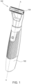
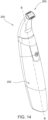
- a handheld hair grooming appliance according to one embodiment is illustrated in the form of an electric handheld hair trimmer, indicated generally by 100. It is contemplated, however, that the embodiments described herein may be used on other handheld hair grooming appliances such as, for example, electric shavers and hair clippers.
- the trimmer 100 includes a handle, indicated generally at 102, and a head (broadly a hair-grooming assembly), indicated generally at 104, mounted on and supported by the handle. Together, the handle 102 and the head 104 generally define a longitudinal axis A-A of the trimmer 100.
- a suitable motor (not shown) is disposed in the handle 102 along with a drive assembly 106 (shown in FIG.
- the drive motor may be powered by one or more batteries (not shown) disposed within the handle 102 and/or by another suitable internal or external electrical power source.
- the head 104 is detachable from the handle 102. Accordingly, the head 104 may be removed and another head 104 may be positioned on the handle 102. However, in other embodiments the head 104 may be affixed to handle 102 without departing from the scope of the invention.
- the head 104 includes a blade assembly 108 operatively connected to the motor by the drive assembly 106, a blade guard 110, and mounting pins 112. Mounting arms project outward from the handle with the head 104 extending laterally between the arms. The mounting pins 112 extend through the respective mounting arm and the blade guard 110 to pivotally mount the head 104 on the handle 102. Accordingly, the head 104 is pivotable about a pivot axis extending through the mounting pins 112. In other embodiments, the position of the head 104 may be fixed (i.e., non-pivotable) relative to the handle 102. In some embodiments, the head 104 may be switched between a pivotable configuration and a non-pivotable configuration. In further embodiments, the head 104 may be pivotable about more than one pivot axis.
- the blade assembly 108 generally comprises a stationary blade 114 and a movable blade 116.
- the drive assembly 106 is operable to laterally reciprocate the movable blade 116 relative to the stationary blade 114 to trim hair. It is understood that the trimmer head 104 may be of other configurations without departing from some aspects of the present invention.
- the stationary blade 114 is suitably a dual-edge blade assembly including a first transverse edge portion 118, a second transverse edge portion 120, and a middle portion 122.
- the first transverse edge portion 118 includes a set of blade teeth 124 defining a first edge 126 of the blade 114.
- the second transverse edge portion 120 includes an opposite set of blade teeth 124 defining a second edge 130 of the blade 114.
- the blade assembly 108 may be a single-edge blade assembly or any other suitable blade assembly that enables the trimmer 100 to operate as described herein.
- first edge 126 and second edge 130 are straight. In other embodiments, the first edge 126 and/or the second edge 130 may be at least partially curved or angled.
- the middle portion 122 is disposed intermediate and spans between the first transverse edge portion 118 and the second transverse edge portion 120 and includes a planar upper surface 132.
- the middle portion 122 may include, without limitation, an apex, a curved surface, an angled surface, and any other suitable portion.
- the middle portion 122 may include an apex connecting the first transverse edge portion 118 and the second transverse edge portion 120.
- the first transverse edge portion 118 includes a first upper surface 134 extending from the first edge 126 to the upper surface 132 of the middle portion 122.
- the second transverse edge portion 120 includes a second upper surface 136 extending from the second edge 130 to the upper surface 132 of the middle portion 122.
- the first upper surface 134 and the second upper surface 136 may include at least one of an angled surface, a concave curve, and a convex curve extending along at least a portion of the respective upper surface 134, 136 between the middle portion 122 and the respective edge 126, 130.
- the first upper surface 134 and the second upper surface 136 are angled. The dual angles thus form the appearance of dual beveled edges on opposite sides of the middle portion 122.
- the terms “bevel” and “beveled” refer to a surface that is oblique to an adjacent surface.
- This beveling of the stationary blade 114 is believed to provide a sharper and more durable blade than conventional blades that are general flat or planar because the stationary blade 114 is beveled from the upper surface 132 to the respective edges 126, 130.
- the bevels of the illustrated stationary blade 114 allow the first transverse edge portion 118 and the second transverse edge portion 120 to come to a relatively sharp point in which the blade is thinner, i.e. sharper, at the first and second edges 126, 130 than for conventional blades.
- the bevels allow the thickness of the stationary blade 114 to change at a constant rate as the blade extends from the middle portion 122 to the respective edges 126, 130.
- the angle of the beveling allows the blade 114 to have an increased thickness in the middle portion 122, which reduces warpage of the blade 114.
- at least some known blades include multiple surfaces with different slopes. In such known blades, there may be high stress areas in portions of the blade where the slope changes. Such conventional blades may also include sections which are thin and plate-shaped. As a result, such blades may deteriorate and even break after repeated use.
- the stationary blade 114 of the illustrated embodiments has a sharper point and increased durability as a result of the bevels.
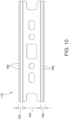
- the illustrated stationary blade 114 has a transversely extending length 137 ( FIG. 7 ). In some embodiments, this length 137 is in the range of about 5 mm to about 50 mm depending on the intended use of the trimmer 100, and more preferably in the range of about 10 mm to about 40 mm. In the illustrated embodiment, the length 137 is approximately 39 mm. In other embodiments, the stationary blade 114 may be of another suitable length and remain within the scope of the invention.
- the stationary blade 114 and the movable blade 116 are in shearing contact with each other to define a cutting plane 138 therebetween.
- the movable blade 116 is configured to contact lower surfaces 140 of the respective first and second transverse edge portions 118, 120 (shown in FIG. 8 ) along the cutting plane 138 as the movable blade reciprocates.
- the upper surface 132 of the middle portion 122 is substantially parallel to the cutting plane 138.
- the first upper surface 134 and the second upper surface 136 (shown in FIG. 8 ) are angled relative to the cutting plane 138.
- the stationary blade 114 is symmetric about a midline of the middle portion 122. Accordingly, the second transverse edge portion 120 has dimensions that are substantially equal to the first transverse edge portion 118. Therefore, the description herein, including dimensions, of the first transverse edge portion 118 may also apply to the second transverse edge portion 120, and vice versa. In other embodiments, the second transverse edge portion 120 and the first transverse edge portion 118 may differ and remain within the scope of the invention.
- the first upper surface 134 extends continuously at a constant slope from the upper surface 132 of the middle portion 122 to the first edge 126.
- the first upper surface 134 thus defines an angle 142 with the cutting plane 138.
- this angle 142 is suitably in the range of about 5° to about 25°, and more preferably in the range of about 10° to about 20°. In the illustrated embodiment, the angle 142 is approximately 15°.
- the first transverse edge portion 118 also has a width 143 ( FIG. 8 ) extending from the first edge 126 to the middle portion 122.
- this width 143 is in the range of about 0.5 mm to about 10 mm, more preferably in the range of about 2 mm to about 6 mm, and even more preferably in the range of about 4 mm to about 5 mm.
- the width 143 of the first transverse edge portion 118 is approximately 4.5 mm.
- the first transverse edge portion 118 further has a generally planar lower surface 140 opposite the first upper surface 134.
- the lower surface 140 is generally parallel to the upper surface 132 of the middle portion 122 and the cutting plane 138.
- the first upper surface 134 extends relative to the lower surface 140 at a constant angle from the first edge 126 to the middle portion 122. Accordingly, with reference to FIG. 9 , the first transverse edge portion 118 has a varying thickness 144 between the first upper surface 134 and the lower surface 140.
- the first transverse edge portion 118 has a minimum thickness 144 at the first edge 126. In some embodiments, the thickness 144 at the first edge 126 is in the range of about 0.02 millimeters (mm) to about 0.07 mm.
- the gaps 148 each have a width 152 at the respective edge 126, 130.
- the width 152 of each gap is in the range of about 0.1 mm to about 0.5 mm. In the illustrated embodiment, the width 152 is approximately 0.3 mm.
- the stationary blade 114 may be formed starting from a sheet material and removing material to form the gaps 148, thus also defining the teeth 124.
- a tool (not shown) may be used to remove the material between the teeth 124 according to a predetermined tool depth 155.
- the tool depth 155 is in the range of about 0.5 mm to about 2 mm. In the illustrated embodiment, the tool depth 155 is approximately 1 mm.
- groove surfaces 156 are formed between the teeth 124. These groove surfaces 156 incline at an angle 158 ( FIG. 9 ) relative to the cutting plane 138 from the lower surface 140 to the respective angled upper surface 134, 136.
- the angle 158 of each groove surface 156 is in the range of 15° to about 45°. In the illustrated embodiment, the angle 158 is approximately 30°. It is understood that in other embodiments the teeth 123 of the stationary blade 114 may be formed in another suitable manner and/or to have other suitable configurations without departing from the scope of this invention.
- the stationary blade 114 is configured to further have a cavity 150 in the lower surface opposite the upper surface 132 of the middle portion 122 of the blade.
- the cavity 150 spans the middle portion and further extends into the first and second transverse edge portions 118, 120.
- the cavity 150 is configured to receive mounting components for connecting the stationary blade 114 to the head 104.
- a post 151 extends through the movable blade 116 and is connected to the middle portion 122 of the stationary blade 114.
- the post 151 may be connected to the stationary blade 114 in any suitable manner.
- the post 151 may be welded to the stationary blade 114.
- the post 151 is integrally formed with the guard 110 and retains the blade assembly 108 within the guard.
- the components of the head 104 may be connected to each other in any manner that enables the trimmer 100 to operate as described.
- the stationary blade 114 may have a reduced thickness along the cavity 150.
- a thickness 154 of the middle portion 122 above the cavity 150 is less than the distance 153 between the upper surface 132 and the cutting plane 138.
- the depth of the cavity 150 is the difference between the distance 153 and the thickness 154.
- the distance 153 is in the range of about 0.5 mm to about 2 mm, more preferably in the range of about 1 mm to about 1.5 mm.
- the thickness 154 is in the range of about 0.25 mm to about 1.25 mm, more preferably in the range of about 0.5 mm to about 1 mm.
- the stationary blade 114 may have any suitable thickness.
- the cavity 150 may be omitted.
- the movable blade 116 includes a first transverse edge portion 160, a second transverse edge portion 162, and a middle portion 164.
- the middle portion 164 extends between the first transverse edge portion 160 and the second transverse edge portion 162 and is substantially planar.
- the first transverse edge portion 160 and the second transverse edge portion 162 extend at angles relative to the cutting plane 138.
- Each of the first transverse edge portion 160 and the second transverse edge portion 162 includes teeth 166.
- the movable blade 116 may have different configurations and be within the scope of the present invention.
- the movable blade 116 has a thickness defined between opposite surfaces of the movable blade.
- the thickness may be in a range from about 0.05 mm to about 0.60 mm.
- the thickness may vary throughout the movable blade 116.
- the movable blade 116 may have a maximum thickness in the middle portion 164 and minimum thicknesses in the teeth 166. In other embodiments, the movable blade 116 may have a different thickness and be within the scope of the invention.
- each comb tooth 172 of the guard 110 has a width 174 that is greater than width 146 of the stationary blade teeth 124 as well as the width of the movable blade teeth 166.
- the width 174 is in the range of about 0.2 mm to about 1.2 mm, and more preferably in the range of about 0.5 mm to about 0.8 mm.
- the comb teeth 172 of the guard 110 are spaced equidistant from each other by suitable gaps 176.
- the gaps 176 have a width 177 in the range of about 1 mm to about 2 mm, more preferably in the range of about 1.25 mm to about 1.75 mm.
- the guard 110 is configured such that the comb teeth 172 of the guard align with approximately every other tooth 166 of the movable blade 116.
- the relatively larger spacing of the comb teeth 172 of the guard 110 allows the stationary blade 114 and the movable blade 116 to cut a greater range of hair lengths.
- the comb teeth 172 arrangement enables long hairs to enter between the teeth 172 and be cut by the blade assembly 108.
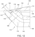
- the comb portions 170 of the guard extend upward and outward past the edges 126, 130 of the stationary blade at an angle 178 relative to the cutting plane 138 of the blade assembly 108.
- the angle 178 of the comb portions 170 of the guard 110 is in the range of about 5° to about 85°, and more suitably in the range of about 20° to about 45°. In the illustrated embodiment, the angle 178 is approximately 30°.
- the comb portions 170 of the guard 110 are angled in this manner, the comb portions are spaced from the respective edges 126, 130 of the stationary blade 114, e.g., to define respective spaces 128 extending perpendicular to the comb portions and extending from the comb portions to the respective edge 126, 130 of the stationary blade.
- the spaces 128 have a width in the range of about 0.1 mm to about 0.5 mm.
- the guard 110 is configured to increase the comfort of the person whose hair is being trimmed.
- the disclosed guard 110 configuration reduces pinching of the user's skin during trimming, e.g., while moving the trimmer over the user's face during trimming.
- the guard 110 configuration also reduces irritation of the skin that would otherwise be caused by the blades 114, 116 directly contacting the skin. It is understood, however, that in other embodiments the guard 110 may be configured other than as illustrated and described herein and remain within some aspects of the present invention.
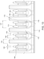
- the guard 110 extends at least to the cutting plane 138.
- the comb portions 170 of the guard 110 extend from the middle portion 168 of the guard 110 proximate the base of the stationary blade 114 to beyond the cutting plane 138. At least some of the comb teeth 171 extend beyond the cutting plane 138 to accommodate flexing of the blades 114, 116 such as in the middle of the blades. Comb teeth 171 located proximate the ends of the blades 114, 116 may extend to and end at the cutting plane 138. In other embodiments, the comb portions 170 of the guard 110 may extend any distance that enables the guard 110 to function as described.
- the guard 110 has a thickness defined between opposite sides of the comb teeth 172 at the cutting plane 138 in a direction parallel to the cutting plane.
- the thickness of the guard may be in a range of about 0.05 mm to about 6 mm.
- the comb teeth 171 have a thickness and/or height that is different from the thickness and/or height of other comb teeth.
- the comb teeth 171 extending proximate the ends of the blades 114, 116 are thinner and shorter than the comb teeth 171 extending proximate the middle of the blades 114, 116. Accordingly, the larger comb teeth 171 may accommodate any flexing of the middle of the blades 114, 116 during operation.
- the increased size of the comb teeth 171 provides increased comfort and further reduces the risk skin being pinched between or contacting the blades 114, 116 at the cutting plane 138.
- the varying thickness and height of the comb teeth 171 is configured to maintain a reduced visual profile of the guard 110.
- the guard 110 may include at least one comb tooth 171 that has a thickness of at least about 0.5 mm or at least about 1.5 mm or at least about 5 mm.
- the guard 110 may include at least one comb tooth 171 that has a thickness of no more than about 0.1 mm.
- the comb teeth 171 may have any thickness that enables the guard 110 to function as described herein.
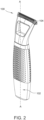
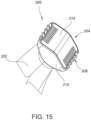
- a second embodiment of an electric hair grooming appliance is generally indicated at 200 ( FIG. 14 ), also in the form of trimmer. More specifically, the illustrated trimmer 200 is similar to the trimmer 100 of the embodiment of Figures 1-13 in that it includes a handle, indicated generally at 202, and a head (broadly, a hair grooming assembly), indicated generally at 204 mounted on the handle. Together the handle 202 and the head 204 generally define a longitudinal axis B-B of the trimmer 200. In this embodiment, the head 204 is fixed, e.g., not pivotable, relative to the handle 202. The head 204 is suitably detachable from the handle 202 for cleaning and/or replacement. However, it is understood that in other embodiments the head 104 may be affixed to handle 102.
- the head 204 includes a blade assembly 208 and a guard 210 configured to receive the blade assembly therein.
- the blade assembly 208 generally comprises a stationary blade 214 and a movable blade 216.
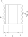
- the stationary blade 214 includes a first transverse edge portion 218, a second transverse edge portion 220, and a middle portion 222 extending therebetween and including a generally planar upper surface 232.
- the first transverse edge portion 218 includes blade teeth 224 defining a first edge 226 of the stationary blade 214.
- the second transverse edge portion 220 includes blade teeth 224 forming a second edge 230 of the stationary blade 214.
- the first transverse edge portion 218 includes a first upper surface 234 extending from the first edge 226 to the upper surface 232, while the second transverse edge portion 220 includes a second upper surface 236 extending from the second edge 230 to the upper surface 232.
- the first upper surface 234 and the second upper surface 236 extend continuously at a constant slope from the respective edges 226, 230 to the upper surface 232 so that the stationary blade is beveled on both transverse sides of the middle portion 222.
- the stationary blade 214 of this embodiment suitably has a length 237 of approximately 12 mm. In other embodiments, however, the length of the stationary blade 214 may be greater or less than 12 mm and remain within the scope of this invention.
- the movable blade 216 includes a first transverse edge portion 260, a second transverse edge portion 262, and a middle portion 264 extending therebetween.
- the middle portion 264 extends between the first transverse edge portion 260 and the second transverse edge portion 262 and is substantially planar.
- the middle portion 264 is substantially parallel to the cutting plane 238 defined by the interface between the stationary blade 214 and the movable blade 216.
- the first transverse edge portion 260 and the second transverse edge portion 262 are angled relative to the cutting plane 238.
- Each of the first transverse edge portion 260 and the second transverse edge portion 262 includes a set of blade teeth 266.
- the movable blade 216 may have different configurations without departing from some aspects of the invention.
- the movable blade 216 is configured to contact lower surfaces 240 of the first and second transverse edge portions 218, 220 of the stationary blade 214 as the movable blade reciprocates.
- the upper surface 232 of the middle portion of the stationary blade 214 is substantially parallel to the cutting plane 238.
- the first upper surface 234 and the second upper surface 236 of the stationary are angled relative to the cutting plane 238 and hence the upper surface 232 of the middle portion 222.
- the lower surfaces 240 of the stationary blade are opposite the respective first and second upper surfaces 234, 236 of the stationary blade.
- the lower surfaces 240 are substantially planar and parallel to the upper surface 232 and the cutting plane 238.
- the stationary blade 214 is symmetric about a midline of the middle portion 222. Accordingly, the second transverse edge portion 220 has dimensions that are substantially equal to the first transverse edge portion 218. Therefore, the description, including dimensions, of the first transverse edge portion 218 may also apply to the second transverse edge portion 220, and vice versa. In other embodiments, the second transverse edge portion 220 and the first transverse edge portion 218 may have some dimensions that differ.
- the first upper surface 234 defines an angle 242 with the cutting plane 238 in the range of about 5° to about 25°, and more preferably in the range of about 10° to about 20°. In the illustrated embodiment, the angle 242 is approximately 15°.
- the first transverse edge portion 218 extends away from the lower surface 240 at a constant angle from the first edge 226 to the middle portion 222. Accordingly, the first transverse edge portion 218 has a varying thickness 244 between the first upper surface 234 and the lower surface 240.
- the first transverse edge portion 218 has a minimum thickness 244 at the first edge 226 in the range of about 0.02 millimeters (mm) to about 0.07 mm. In the illustrated embodiment, the thickness 244 at the first edge 226 is approximately 0.06 mm.
- each of the first and second transverse edge portions 218, 220 includes respective blade teeth 224 at least partially forming the edges 226, 230.
- Each tooth has a width 250 at the respective edge 226, 230 in the range of about 0.2 mm to about 1 mm, and more preferably in the range of about 0.3 mm to about 0.6 mm.
- the width 250 of each blade tooth 224 is approximately 0.5 mm.
- the teeth 124 are spaced by suitable gaps 248 having a width 252 at the respective edge 226, 230 in the range of about 0.1 mm to about 0.5 mm.
- the width 252 is approximately 0.3 mm.
- the guard 210 is generally V-shaped in cross-section and includes a middle portion 268 and opposed comb portions 270 extending outward and upward from the middle portion to form an interior space for receiving the blade assembly 208 into the guard.
- the guard 210 is configured to receive the blade assembly 208 such that the comb portions 270 extend in proximity to but otherwise outward of the edges 226, 230 of the stationary blade 214.
- the comb portions 270 include comb teeth 272 that extend adjacent the stationary blade teeth 224 and the movable blade teeth 266.
- the guard 210 may have other configurations without departing from some aspects of the invention.
- each comb tooth 272 has a width 274 that is greater than the respective widths of the stationary blade teeth 224 and the movable blade teeth 266.
- the width 274 of each comb tooth is in the range of about 0.5 mm to about 1 mm, more preferably in the range of about 0.6 mm to about 0.8 mm.
- the comb teeth are suitably spaced from each by gaps 276 each having a gap width 277 in the range of about 1 mm to about 2 mm, and more preferably in the range of about 1.5 mm to about 1.8 mm.
- the comb teeth 272 and gap width 277 is such that two stationary blade teeth 224 are capable of positioning between each adjacent pair of comb teeth 272.
- the comb portion 270 extends past the blade assembly 208 at an angle 278 relative to the cutting plane 238.
- the angle 278 is in the range of about 5° to about 85°, and more preferably in the range of about 20° to about 45°.
- the comb portions 270 are spaced from the respective edges 226, 230 of the stationary blade 214 to define spaces 228 therebetween on opposite sides of the stationary blade 214 - as determined perpendicular to the comb portion and extending from the comb portion to the respective edge of the stationary blade.
- each space 228 has a width in the range of about 0.1 mm to about 0.5 mm.
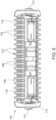
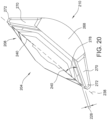
- FIGS. 21-23 an embodiment of a head for use with hair grooming appliance 100 (shown in FIG. 1 ) and hair grooming appliance 200 (shown in FIG. 2 ) is generally indicated at 300 ( FIG. 21 ).
- the head 300 includes a blade assembly 302 and a guard 304 configured to receive the blade assembly therein.
- the blade assembly 302 generally comprises a stationary blade 306 and a movable blade 308 ( FIG. 22 ).
- the head 300 may have other configurations without departing from some aspects of this invention.
- the stationary blade 306 has a varying thickness and is configured to allow the blade assembly 302 to cut hairs close to a user's skin.
- the stationary blade 306 is configured to reduce irritation to the skin during operation.
- the thick portions of the stationary blade 306 prevent flexing of the stationary blade 306 during operation.
- the thin portions of the stationary blade 306 facilitate the blade assembly 302 cutting hairs close to the skin.
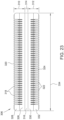
- the stationary blade 306 includes a first transverse edge portion 310, a second transverse edge portion 312, and a middle portion 314 extending therebetween and including a generally planar upper surface 316.
- the first transverse edge portion 310 includes blade teeth 318 forming a first edge 320 of the stationary blade 306.
- the second transverse edge portion 312 includes blade teeth 322 forming a second edge 324 of the stationary blade 306.
- the stationary blade 306 of this embodiment suitably has a transversely extending length 334 of approximately 39 mm. In other embodiments, however, the length of the stationary blade 306 may be greater or less than 39 mm and remain within the scope of this invention.
- the first transverse edge portion 310 includes a first upper surface 326 and a first curved upper surface 328.
- the first upper surface 326 extends from the planar upper surface 316 to the first curved upper surface 328.
- the first curved upper surface 328 extends from the first upper surface 326 to the first edge 320.
- the second transverse edge portion 312 includes a second upper surface 330 and a second curved upper surface 332.
- the second upper surface 330 extends from the upper surface 316 to the second curved upper surface 332.
- the second curved upper surface 332 extends from the second upper surface 330 to the second edge 324.
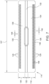
- the stationary blade 306 has a reduced thickness along the first curved upper surface 328 and the second curved upper surface 332.
- the stationary blade 306 has a minimum thickness 336 defined between each curved upper surface 328, 332 and the respective planar lower surface 337 of the stationary blade 306.
- the planar lower surfaces 337 are configured to contact the movable blade 308.
- the minimum thickness 336 is in a range of about 0.05 mm to about 0.1 mm. In this embodiment, the minimum thickness 336 is approximately 0.08 mm.
- the first curved upper surface 328 and the second curved upper surface 332 each have a radius 338.
- Each radius 338 may be any suitable radius that enables the stationary blade to function as described herein.
- the first edge 320 and the second edge 324 of the stationary blade 306 are located a distance 340 from edges 335 of the movable blade 308.
- the distance 340 is measured along a cutting plane 342 of the blade assembly 302.
- the distance 340 prevents the movable blade 308 contacting the user's skin during operation.
- the distance 340 is in a range of about 0.5 mm to about 2 mm. In this embodiment, the distance 340 is approximately 1 mm.
- the stationary blade 306 has a tip thickness 344 at the first edge 320 and the second edge 324.
- the concave curves of the first curved upper surface 328 and the second curved upper surface 332 allow the tip thickness 344 to be greater than the minimum thickness 336.
- the tip thickness 344 allows for laser ball tips to be incorporated into stationary blade 306.
- the tip thickness 344 is in a range of about 0.1 mm to about 0.5 mm.
- the tip thickness 344 is approximately 0.16 mm without laser ball tips and approximately 0.24 mm including laser ball tips.
- the stationary blade 306 may have other tips without departing from some aspects of this invention.
- a trimmer in some embodiments, includes a handle, a drive assembly in the handle, and a head attached to the handle.
- the head includes a stationary blade including a first transverse edge portion, a second transverse edge portion, and a middle portion connecting the first transverse edge portion and the second transverse edge portion.
- the first transverse edge portion includes blade teeth defining a first edge of the blade.
- the second transverse edge portion includes blade teeth defining a second edge of the blade.
- the first transverse edge portion further includes a first upper surface extending from the first edge to the middle portion and the second transverse edge portion further includes a second upper surface extending from the second edge to the upper surface of the middle portion.
- the first upper surface includes at least one of an angled surface, a concave surface, and a convex surface along at least a portion of the extension of the first upper surface between the middle portion and the first edge.
- the head also includes a movable blade in shearing contact with the first transverse edge portion and the second transverse edge portion of the stationary blade.
- the drive assembly is configured to reciprocate the movable blade relative to the stationary blade.
- the second upper surface includes at least one of an angled surface, a concave curve, and a convex curve extending along at least a portion of the extension of the second upper surface between the middle portion and the first edge.
- the middle portion includes a substantially planar upper surface extending between the first upper surface and the second upper surface.
- the stationary blade and the movable blade are in contact with each other to define a cutting plane that is substantially planar and parallel to the upper surface of the middle portion of the stationary blade.
- the first upper surface is angled relative to the cutting plane.
- an angle between the first upper surface and the cutting plane is in the range of about 5° to about 25°.
- the angle between the first upper surface and the cutting plane is in the range of about 10° to about 20°.
- the stationary blade has a thickness at the first edge in a range of about 0.02 millimeters (mm) to about 0.07 mm.
- the thickness of the stationary blade at the first edge is approximately 0.06 mm.
- the first upper surface includes a curve extending along a portion of the extension of the first upper surface between the middle portion and the first edge.
- the second upper surface includes a curve extending along a portion of the extension of the second upper surface between the middle portion and the second edge.
- the stationary blade has a minimum thickness defined by the first upper surface in a range of about 0.05 mm to about 0.1 mm.
- the stationary blade has a tip thickness in a range of about 0.1 mm to about 0.5 mm.
- the first upper surface includes a concave curve.
- a trimmer in other embodiments, includes a handle, a drive assembly in the handle, and a blade assembly configured for operative connection to the drive assembly.
- the blade assembly includes a stationary blade including blade teeth. Each blade tooth has a width.
- the blade assembly also includes a movable blade including blade teeth.
- the drive assembly is operable to reciprocate the movable blade relative to the stationary blade.
- the blade assembly further includes a guard disposed outward of and extending in proximity to the respective blade teeth of the stationary blade and movable blade.
- the guard includes comb teeth. Each comb tooth has a width that is greater than the width of each stationary blade tooth.
- the stationary blade and the movable blade together define a cutting plane.
- the guard extends at least to the cutting plane.
- the blade assembly is pivotably connected to the handle.
- the width of each blade tooth of the stationary blade is in the range of about 0.2 mm to about 1 mm.
- the blade teeth of the stationary blade are spaced by gaps having a width in the range of about 0.2 mm to about 0.5 mm.
- the width of each comb tooth is in the range of about 0.5 mm to about 1.2 mm.
- the comb teeth of the guard are spaced by gaps.
- Each gap has a width in the range of about 1 mm to about 2 mm.
- a hair grooming appliance in other embodiments, includes a handle, a drive assembly in the handle, and a head attached to the handle.
- the head includes a blade assembly including a stationary blade and a movable blade.
- the drive assembly is operable to reciprocate the movable blade relative to the stationary blade.
- Each of the stationary blade and the movable blade includes respective blade teeth.
- the blade teeth of the stationary blade teeth define a first blade edge and a second blade edge of the stationary blade.
- the stationary blade includes a first transverse edge portion, a second transverse edge portion, and a middle portion extending therebetween.
- the first transverse edge portion has a first upper surface extending from the first edge of the stationary blade to the middle portion.
- the second transverse edge portion includes a second upper surface extending from the second edge of the stationary blade to the middle portion.
- the first upper surface includes at least one of an angled surface, a concave surface, and a convex surface along at least a portion of the extension of the first upper surface between the middle portion and the first edge.
- the second upper surface includes at least one of an angled surface, a concave surface, and a convex surface along at least a portion of the extension of the second upper surface between the middle portion and the second edge.
- the head also includes a guard configured to receive the blade assembly therein and having opposed comb portions disposed in proximity to the first and second edges of the stationary blade. Each of the comb portions has comb teeth.
- the stationary blade and the movable blade define a cutting plane therebetween.
- An angle between the first upper surface and the cutting plane is in the range of about 5° to about 25°.
- the comb portions of the guard are spaced from the first and second edges of the stationary blade in the range of about 0.1 mm to about 0.5 mm as determined perpendicular to the respective comb portion.
- the head is pivotably attached to the handle.
- embodiments of a trimmer include a blade that includes at least one beveled edge.
- the blade is a double-edged blade and includes two beveled edges.
- the beveled edges allow the blade to be sharper than conventional blades while also being more durable than at least some known blades. Accordingly, the blade may have a longer service life.
- the trimmer may cost less to assemble than at least some known trimmers.
- embodiments of the trimmer include a blade including a curved or recessed surface along the beveled edge.
- the curved surface allows the blade to be thinner adjacent cutting edges of a movable blade to provide a closer trim.
- the blade includes relatively thick portions that resist flexing of the blade.
- the curved surface is concave and allows the blade to have thicker tips.
- embodiments of the trimmer include a guard having comb teeth in spaced proximity to the blade assembly.
- the guard protects the skin of a person as the trimmer is moved along the skin.
- the guard allows the blade assembly to cut a greater range of hairs.
- an apparatus, system, and methods for a hair grooming appliance are described above in detail.
- the apparatus, system, and methods described herein are not limited to the specific embodiments described, but rather, components of apparatus, systems, and/or steps of the methods may be utilized independently and separately from other components and/or steps described herein.
- the methods may also be used in combination with other hair grooming appliances, systems, and methods, and are not limited to practice with only the apparatuses, systems, and methods described herein. Rather, the exemplary embodiments can be implemented and utilized in connection with many grooming applications.
Landscapes
- Life Sciences & Earth Sciences (AREA)
- Forests & Forestry (AREA)
- Engineering & Computer Science (AREA)
- Mechanical Engineering (AREA)
- Dry Shavers And Clippers (AREA)
Claims (12)
- Kopf (104) für eine elektrische Hand-Haarschneidemaschine (100), wobei der Kopf (104) umfasst:eine Klingenanordnung (108), die umfasst:(i) eine stationäre Klinge (114), die beinhaltet:einen ersten querliegenden Kantenabschnitt (118), der eine erste obere Oberfläche (134) und Klingenzähne (124) beinhaltet, wobei die Klingenzähne eine erste Kante (126) der stationären Klinge definieren;einen zweiten querliegenden Kantenabschnitt (120), der eine zweite obere Oberfläche (136) und Klingenzähne (124) beinhaltet, wobei die Klingenzähne eine zweite Kante (130) der stationären Klinge definieren; undeinen Mittenabschnitt (122), der den ersten querliegenden Kantenabschnitt und den zweiten querliegenden Kantenabschnitt verbindet, wobei der Mittenabschnitt im Wesentlichen eine ebene obere Oberfläche (132) beinhaltet, die sich zwischen der ersten oberen Oberfläche und der zweiten oberen Oberfläche erstreckt, eine untere Oberfläche, entgegengesetzt zur ebenen oberen Oberfläche, und einen Hohlraum (150) in der unteren Oberfläche, wobei der Hohlraum (150) den Mittenabschnitt überspannt und sich weiter in den ersten und zweiten querliegenden Kantenabschnitt (118, 120) erstreckt,die erste obere Oberfläche, die sich von der ersten Kante zum Mittenabschnitt erstreckt, wobei sich die zweite obere Oberfläche von der zweiten Kante zum Mittenabschnitt erstreckt, der erste querliegende Kantenabschnitt und der zweite querliegende Kantenabschnitt vom mittleren Abschnitt zu den jeweiligen Kanten der stationären Klinge abgeschrägt sind, wobei die stationäre Klinge symmetrisch um eine Mittellinie des Mittenabschnitts ist; und(ii) eine bewegbare Klinge (116) in Scherkontakt mit dem ersten querliegenden Kantenabschnitt und dem zweiten querliegenden Kantenabschnitt der stationären Klinge; undder Kopf (104) weiter eine Montagekomponente umfasst, die mit dem Mittenabschnitt der stationären Klinge zum Verbinden der stationären Klinge mit dem Kopf (104) verbunden ist, wobei die Montagekomponente eine Stütze (151) umfasst, die sich durch die bewegbare Klinge hindurch erstreckt und in dem Hohlraum in der unteren Oberfläche aufgenommen ist, dadurch gekennzeichnet, dass die Stütze (151) fest mit der unteren Oberfläche des Mittenabschnitts der stationären Klinge verbunden ist.
- Kopf nach Anspruch 1, wobei die erste obere Oberfläche mindestens eine von einer abgewinkelten Oberfläche, einer konkaven Oberfläche und einer konvexen Oberfläche entlang mindestens eines Abschnitts der Erstreckung der ersten oberen Oberfläche zwischen dem Mittenabschnitt und der ersten Kante beinhaltet.
- Kopf nach Anspruch 2, wobei die zweite obere Oberfläche mindestens eine von einer abgewinkelten Oberfläche, einer konkaven Kurve und einer konvexen Kurve, die sich entlang mindestens eines Abschnitts der Erstreckung der zweiten oberen Oberfläche zwischen dem Mittenabschnitt und der zweiten Kante erstreckt, beinhaltet.
- Kopf nach Anspruch 3, wobei die stationäre Klinge und die bewegbare Klinge in Kontakt miteinander sind, um eine Schnittebene (138) zu definieren, die im Wesentlichen eben und parallel zur oberen Oberfläche des Mittenabschnitts der stationären Klinge ist.
- Kopf nach Anspruch 4, wobei die erste obere Oberfläche in Bezug zur Schnittebene abgewinkelt ist, wobei ein Winkel (142) zwischen der ersten oberen Oberfläche und der Schnittebene im Bereich von etwa 5° bis etwa 25° liegt.
- Kopf nach Anspruch 5, wobei der Winkel zwischen der ersten oberen Oberfläche und der Schnittebene im Bereich von etwa 10° bis etwa 20° liegt.
- Kopf nach Anspruch 1, wobei die stationäre Klinge eine Dicke an der ersten Kante in einem Bereich von etwa 0,02 Millimetern (mm) bis etwa 0,07 mm aufweist.
- Kopf nach Anspruch 7, wobei die Dicke der stationären Klinge an der ersten Kante annähernd 0,06 mm beträgt.
- Kopf nach einem vorstehenden Anspruch, weiter umfassend:eine Schutzvorrichtung (110), die einen Innenraum definiert, der konfiguriert ist, um die stationäre Klinge (114) und die bewegbare Klinge (116) aufzunehmen, wobei die Schutzvorrichtung (110) einen Mittenabschnitt (168) und Kammquerabschnitte (170), die sich von dem Mittenabschnitt (168) entlang der ersten und zweiten querliegenden Kantenabschnitte (118, 120) der stationären Klinge (114) erstrecken, beinhaltet, wobei die Kammabschnitte (170) jeweils einen jeweiligen Satz von Kammzähnen (172) beinhalten, die den entsprechenden Zähnen (124) der stationären Klinge (114) und zugeordneten Zähnen (1669) der bewegbaren Klinge (116) entsprechen und sich in deren Nähe befinden, und wobei die Schutzvorrichtung im Querschnitt im Allgemeinen V-förmig ist,
- Kopf nach Anspruch 9, wobei die Stütze (151) integral mit der Schutzvorrichtung (110) gebildet ist und die Klingenanordnung (108) innerhalb der Schutzvorrichtung hält.
- Kopf nach einem vorstehenden Anspruch, wobei die Stütze (151) mit der stationären Klinge verschweißt ist.
- Elektrische Hand-Haarschneidemaschine (100), die umfasst:einen Griff (102);eine Antriebsanordnung (106) in dem Griff; undeinen Kopf (104) nach einem vorstehenden Anspruch, der an dem Griff angebracht ist,wobei die Antriebsanordnung betreibbar ist, um die bewegbare Klinge in Bezug auf die stationäre Klinge hin- und her zu bewegen.
Applications Claiming Priority (3)
| Application Number | Priority Date | Filing Date | Title |
|---|---|---|---|
| US201762463918P | 2017-02-27 | 2017-02-27 | |
| EP18757523.8A EP3585574B1 (de) | 2017-02-27 | 2018-02-27 | Elektrische handhaarschneidemaschine mit klingenschutz |
| PCT/US2018/019891 WO2018157113A1 (en) | 2017-02-27 | 2018-02-27 | Electric handheld hair trimmer with blade guard |
Related Parent Applications (2)
| Application Number | Title | Priority Date | Filing Date |
|---|---|---|---|
| EP18757523.8A Division EP3585574B1 (de) | 2017-02-27 | 2018-02-27 | Elektrische handhaarschneidemaschine mit klingenschutz |
| EP18757523.8A Division-Into EP3585574B1 (de) | 2017-02-27 | 2018-02-27 | Elektrische handhaarschneidemaschine mit klingenschutz |
Publications (2)
| Publication Number | Publication Date |
|---|---|
| EP4032668A1 EP4032668A1 (de) | 2022-07-27 |
| EP4032668B1 true EP4032668B1 (de) | 2025-05-28 |
Family
ID=63253046
Family Applications (2)
| Application Number | Title | Priority Date | Filing Date |
|---|---|---|---|
| EP22159259.5A Active EP4032668B1 (de) | 2017-02-27 | 2018-02-27 | Elektrische handhaarschneidemaschine mit klingenschutz |
| EP18757523.8A Active EP3585574B1 (de) | 2017-02-27 | 2018-02-27 | Elektrische handhaarschneidemaschine mit klingenschutz |
Family Applications After (1)
| Application Number | Title | Priority Date | Filing Date |
|---|---|---|---|
| EP18757523.8A Active EP3585574B1 (de) | 2017-02-27 | 2018-02-27 | Elektrische handhaarschneidemaschine mit klingenschutz |
Country Status (6)
| Country | Link |
|---|---|
| US (4) | US11104016B2 (de) |
| EP (2) | EP4032668B1 (de) |
| CN (2) | CN115284338A (de) |
| GB (1) | GB2573960B (de) |
| RU (2) | RU2021133268A (de) |
| WO (1) | WO2018157113A1 (de) |
Families Citing this family (27)
| Publication number | Priority date | Publication date | Assignee | Title |
|---|---|---|---|---|
| EP4032668B1 (de) | 2017-02-27 | 2025-05-28 | Spectrum Brands, Inc. | Elektrische handhaarschneidemaschine mit klingenschutz |
| EP3388206A1 (de) * | 2017-04-14 | 2018-10-17 | Koninklijke Philips N.V. | Aufsteckkamm, schneidkopf und haarschneidegerät |
| CN208342890U (zh) | 2017-05-15 | 2019-01-08 | A·库班尼 | 毛发修剪装置 |
| USD952946S1 (en) | 2017-09-01 | 2022-05-24 | Church & Dwight Co., Inc. | Hair removal device |
| EP3466619A1 (de) * | 2017-10-05 | 2019-04-10 | Koninklijke Philips N.V. | Schaufelsatz und herstellungsverfahren |
| USD914977S1 (en) | 2019-07-19 | 2021-03-30 | Church & Dwight Co., Inc. | Handle for hair removal apparatus |
| USD925830S1 (en) * | 2019-07-19 | 2021-07-20 | Church & Dwight Co., Inc. | Head assembly for hair removal apparatus |
| USD936899S1 (en) * | 2019-10-18 | 2021-11-23 | Church & Dwight Co., Inc. | Hair removal apparatus |
| USD914978S1 (en) | 2019-10-18 | 2021-03-30 | Church & Dwight Co., Inc. | Hair removal apparatus |
| USD935095S1 (en) | 2019-11-05 | 2021-11-02 | Church & Dwight Co., Inc. | Guard for hair removal device |
| USD921293S1 (en) * | 2019-11-05 | 2021-06-01 | Church & Dwight Co., Inc. | Guard for hair removal device |
| USD942687S1 (en) | 2019-11-18 | 2022-02-01 | Church & Dwight Co., Inc. | Articulating blade assembly for hair removal device |
| USD940958S1 (en) | 2019-11-18 | 2022-01-11 | Church & Dwight Co., Inc. | Articulating blade assembly for hair removal device |
| EP3854541B1 (de) | 2020-01-23 | 2024-06-26 | Braun GmbH | Elektrischer bartschneider |
| EP3854542B1 (de) * | 2020-01-23 | 2023-12-13 | Braun GmbH | Elektrischer bartschneider |
| EP3854538B1 (de) * | 2020-01-23 | 2024-10-16 | Braun GmbH | Elektrischer bartschneider |
| EP3854540B1 (de) | 2020-01-23 | 2025-03-19 | Braun GmbH | Elektrischer bartschneider |
| USD968707S1 (en) * | 2020-04-09 | 2022-11-01 | Koninklijke Philips N.V. | Grooming apparatus |
| USD1010223S1 (en) * | 2020-11-06 | 2024-01-02 | Braun Gmbh | Hair removal device |
| USD1041752S1 (en) | 2020-05-08 | 2024-09-10 | Braun Gmbh | Hair removal device |
| CN112873285A (zh) * | 2021-03-15 | 2021-06-01 | 浙江美森电器有限公司 | 中间刀及剃须刀 |
| EP4119312B1 (de) * | 2021-07-15 | 2025-03-19 | Braun GmbH | Schneidsystem für einen elektrischen barttrimmer |
| US20250242509A1 (en) * | 2021-11-12 | 2025-07-31 | Yuanhai Medical Technology Co., Ltd | Static cutter of hair cutter and hair cutter |
| USD1024442S1 (en) * | 2022-01-28 | 2024-04-23 | Cdi Beauty Corp. | Grooming device |
| USD1082145S1 (en) * | 2022-02-25 | 2025-07-01 | Koninklijke Philips N.V. | Head for shaver |
| USD999984S1 (en) * | 2022-11-22 | 2023-09-26 | Yiwu Waha Home Appliance Co., Ltd. | Hair trimmer |
| USD999986S1 (en) * | 2022-11-22 | 2023-09-26 | Yiwu Waha Home Appliance Co., Ltd. | Hair trimmer |
Family Cites Families (68)
| Publication number | Priority date | Publication date | Assignee | Title |
|---|---|---|---|---|
| US2200185A (en) * | 1936-03-12 | 1940-05-07 | Gillette Safety Razor Co | Shaving implement |
| US2152815A (en) * | 1936-04-10 | 1939-04-04 | Gillette Safety Razor Co | Shaving implement |
| US2107207A (en) * | 1936-05-19 | 1938-02-01 | Gillette Safety Razor Co | Shaving implement |
| CH191061A (fr) * | 1936-06-18 | 1937-05-31 | Helios Daniel Charpilloz Frere | Tondeuse à barbe. |
| US2210110A (en) * | 1936-07-27 | 1940-08-06 | Jr Matthew G Andis | Shaving device |
| US2223205A (en) * | 1936-12-05 | 1940-11-26 | American Safety Razor Corp | Dry shaver |
| US2326192A (en) * | 1937-02-06 | 1943-08-10 | Andis Clipper Co | Shaving device |
| US2216797A (en) * | 1938-01-06 | 1940-10-08 | Andis Mathew | Shaving device |
| US2190481A (en) * | 1938-06-23 | 1940-02-13 | Barney R Nyhagen | Dry shaver |
| US2345695A (en) * | 1939-02-08 | 1944-04-04 | Andis Clipper Co | Dry shaving device |
| CH211529A (fr) * | 1939-05-20 | 1940-09-30 | Affolter Andre | Rasoir mécanique à lame à mouvement rectiligne alternatif. |
| US2293637A (en) * | 1941-07-21 | 1942-08-18 | Telesphore Arguin | Electric clipper |
| US2395495A (en) * | 1943-07-05 | 1946-02-26 | Thomas J Murphy | Dry shaver |
| US2544397A (en) | 1945-09-01 | 1951-03-06 | Curtiss Wright Corp | Sliding cockpit enclosure for aircraft |
| US2484610A (en) * | 1945-09-25 | 1949-10-11 | Cromonic Joseph | Double cutter hair clipper |
| US2544897A (en) * | 1946-02-26 | 1951-03-13 | Hans Lanzl | Shaving device |
| US3279056A (en) * | 1964-10-28 | 1966-10-18 | Andis Clipper Co | Double-edge combination dry shaver and finishing hair clipper with adjustable head |
| US3648370A (en) * | 1970-04-03 | 1972-03-14 | Daniel Cercone | Shoe comb and attachment |
| AT349357B (de) * | 1977-05-03 | 1979-04-10 | Philips Nv | Scherkopf fuer trockenrasierapparate |
| JPS55155A (en) * | 1978-07-17 | 1980-01-05 | Matsushita Electric Works Ltd | Fixed edge of electric razor for shaving edge |
| JPS58127685A (ja) * | 1982-01-26 | 1983-07-29 | 松下電工株式会社 | 電気かみそり |
| JPS5917383A (ja) * | 1982-07-21 | 1984-01-28 | 九州日立マクセル株式会社 | 電気かみそりの櫛状刃体の製造方法 |
| US4724614A (en) * | 1986-04-01 | 1988-02-16 | Wahl Clipper Corporation | Blade attachments for electric beard trimmers |
| NL8700516A (nl) * | 1987-03-04 | 1988-10-03 | Philips Nv | Knipeenheid. |
| US5054997A (en) * | 1989-11-22 | 1991-10-08 | General Electric Company | Blade tip clearance control apparatus using bellcrank mechanism |
| JP3017508B2 (ja) | 1989-12-25 | 2000-03-13 | 松下電工株式会社 | ヘアカッター |
| JPH05293264A (ja) * | 1992-04-23 | 1993-11-09 | Matsushita Electric Works Ltd | ヘアカッター |
| DE4413352C1 (de) | 1994-04-18 | 1995-05-04 | Braun Ag | Verfahren zur Herstellung eines Messers für eine Schneideinrichtung eines elektrischen Rasierapparates oder Bartschneiders |
| US5504997A (en) * | 1994-10-18 | 1996-04-09 | Lee; Ming H. | Blade holder assembly for an electric razor |
| US5606799A (en) * | 1994-10-21 | 1997-03-04 | Wahl Clipper Corporation | Detachable pivoting clipper blades |
| GB9700037D0 (en) * | 1997-01-03 | 1997-02-19 | Gillette Co | Safety razors |
| DE19822094C2 (de) | 1998-05-16 | 2000-03-02 | Braun Gmbh | Trockenrasierapparat |
| US6393702B1 (en) * | 1998-12-29 | 2002-05-28 | Kim Laube | Disposable cutting head for clippers |
| DE19939509C2 (de) | 1999-08-20 | 2001-09-06 | Braun Gmbh | Haarschneidemaschine |
| US6536116B2 (en) | 2001-01-12 | 2003-03-25 | Conair Cip, Inc. | Hair clipper with rotating blade assembly |
| JP4466077B2 (ja) | 2003-12-26 | 2010-05-26 | パナソニック電工株式会社 | ヘアカッター |
| EP1866129B1 (de) | 2005-03-31 | 2009-11-25 | Koninklijke Philips Electronics N.V. | Haarschneidvorrichtung mit kammeinheit |
| DE202006007059U1 (de) * | 2005-12-12 | 2006-10-12 | Koninklijke Philips Electronics N.V. | Schneideeinheit mit Schutzzähnen und Haarschneidevorrichtung |
| US8769828B2 (en) * | 2007-01-14 | 2014-07-08 | Specialife Industries Limited | Blade set for hair clippers |
| US7900359B2 (en) | 2007-08-31 | 2011-03-08 | The Gillette Company | Hair trimmer |
| DE102007050379A1 (de) * | 2007-10-22 | 2009-04-23 | Braun Gmbh | Haartrimmer |
| ATE532613T1 (de) * | 2008-01-29 | 2011-11-15 | Braun Gmbh | Schneidekamm, haarschneidegerät mit einem schneidekamm und herstellungsverfahren für einen schneidekamm |
| EP2085194A1 (de) * | 2008-01-29 | 2009-08-05 | Braun GmbH | Schneidekamm, Haarschneidegerät mit einem Schneidekamm und Herstellungsverfahren für einen Schneidekamm |
| US8132540B1 (en) * | 2009-02-27 | 2012-03-13 | Timothy Lee Strebeigh | Trimmer |
| JP5406769B2 (ja) | 2010-03-26 | 2014-02-05 | パナソニック株式会社 | 電気かみそり |
| CN201745013U (zh) * | 2010-07-30 | 2011-02-16 | 设计制造有限公司 | 适合人手握持并方便剃除背部毛发的电动剃毛器 |
| JP5238051B2 (ja) * | 2011-03-22 | 2013-07-17 | パナソニック株式会社 | トリマー刃 |
| CN103945995B (zh) * | 2011-11-17 | 2016-08-24 | 皇家飞利浦有限公司 | 用于毛发修剪器的皮肤保护器 |
| CN202607699U (zh) * | 2012-06-14 | 2012-12-19 | 浙江百特电器有限公司 | 带软性限位梳的理发器 |
| CN102744736B (zh) * | 2012-07-26 | 2014-11-12 | 珠海新秀丽家居用品有限公司 | 双刀体毛修剪器 |
| RU2529359C2 (ru) | 2012-09-19 | 2014-09-27 | Федеральное государственное бюджетное учреждение "Научно-исследовательский институт вакцин и сывороток им. И.И. Мечникова" Российской академии медицинских наук (ФГБУ "НИИВС им. И.И. Мечникова" РАМН) | РЕКОМБИНАНТНАЯ ПЛАЗМИДНАЯ ДНК pPA-OPRF-ETA, КОДИРУЮЩАЯ СИНТЕЗ РЕКОМБИНАНТНОГО БЕЛКА OPRF-ETA Pseudomonas aeruginosa, ШТАММ Escherichia coli PA-OPRF-ETA - ПРОДУЦЕНТ РЕКОМБИНАНТНОГО БЕЛКА OPRF-ETA Pseudomonas aeruginosa И СПОСОБ ПОЛУЧЕНИЯ РЕКОМБИНАНТНОГО БЕЛКА OPRF-ETA Pseudomonas aeruginosa |
| JP6124048B2 (ja) * | 2012-12-26 | 2017-05-10 | パナソニックIpマネジメント株式会社 | 電気バリカン |
| JP6397917B2 (ja) * | 2013-08-29 | 2018-09-26 | コーニンクレッカ フィリップス エヌ ヴェKoninklijke Philips N.V. | ヘアクリッピング装置 |
| EP2857154B1 (de) * | 2013-10-01 | 2019-02-20 | Koninklijke Philips N.V. | Klingensatz und Haarschneideanwendung |
| EP2857155A1 (de) * | 2013-10-01 | 2015-04-08 | Koninklijke Philips N.V. | Klingensatz und Haarschneidegerät |
| US10391648B2 (en) * | 2014-01-01 | 2019-08-27 | Daniel Lawrence Roth | Shaving and grooming apparatus |
| RU2676812C2 (ru) * | 2014-03-31 | 2019-01-11 | Конинклейке Филипс Н.В. | Устройство для стрижки волос |
| US10751891B2 (en) * | 2014-04-18 | 2020-08-25 | Koninklijke Philips N.V. | Blade set, hair cutting appliance, and related manufacturing method |
| JP6110572B2 (ja) * | 2014-09-18 | 2017-04-05 | コーニンクレッカ フィリップス エヌ ヴェKoninklijke Philips N.V. | 切断ヘッド及び毛切断器具 |
| EP3037223B1 (de) * | 2014-12-23 | 2019-05-08 | Braun GmbH | Trockenrasierer |
| JP6357282B2 (ja) * | 2015-02-04 | 2018-07-11 | コーニンクレッカ フィリップス エヌ ヴェKoninklijke Philips N.V. | 切断ヘッド及び毛切断装置 |
| PL3142834T3 (pl) * | 2015-02-26 | 2018-12-31 | Koninklijke Philips N.V. | Nasadka grzebieniowa i urządzenie do cięcia włosów |
| EP3288727B1 (de) * | 2015-04-28 | 2019-09-04 | Koninklijke Philips N.V. | Klingensatz und haarschneideanwendung |
| CN107635733B (zh) * | 2015-05-19 | 2020-10-13 | 皇家飞利浦有限公司 | 固定刀片的制造方法和固定刀片 |
| CN204658730U (zh) * | 2015-06-09 | 2015-09-23 | 宁波科论太阳能有限公司 | 单晶硅棒的切割工装 |
| CN104999485B (zh) | 2015-08-20 | 2019-07-23 | 珠海新秀丽家居用品有限公司 | 具有超薄定刀的新型个人护理修剪器 |
| CN106346519B (zh) * | 2016-10-12 | 2019-12-17 | 中山市小石陶瓷刀片有限公司 | 一种往复式电动剃毛刀头 |
| EP4032668B1 (de) | 2017-02-27 | 2025-05-28 | Spectrum Brands, Inc. | Elektrische handhaarschneidemaschine mit klingenschutz |
-
2018
- 2018-02-27 EP EP22159259.5A patent/EP4032668B1/de active Active
- 2018-02-27 WO PCT/US2018/019891 patent/WO2018157113A1/en not_active Ceased
- 2018-02-27 GB GB1912271.2A patent/GB2573960B/en active Active
- 2018-02-27 RU RU2021133268A patent/RU2021133268A/ru unknown
- 2018-02-27 CN CN202210938016.1A patent/CN115284338A/zh active Pending
- 2018-02-27 US US16/489,253 patent/US11104016B2/en active Active
- 2018-02-27 EP EP18757523.8A patent/EP3585574B1/de active Active
- 2018-02-27 RU RU2019130324A patent/RU2759924C2/ru active
- 2018-02-27 CN CN201880026825.7A patent/CN110891745B/zh active Active
-
2021
- 2021-08-30 US US17/461,643 patent/US11577413B2/en active Active
-
2023
- 2023-01-12 US US18/096,506 patent/US11999071B2/en active Active
-
2024
- 2024-04-30 US US18/650,590 patent/US20240278441A1/en not_active Abandoned
Also Published As
| Publication number | Publication date |
|---|---|
| CN115284338A (zh) | 2022-11-04 |
| EP4032668A1 (de) | 2022-07-27 |
| US20210387365A1 (en) | 2021-12-16 |
| GB201912271D0 (en) | 2019-10-09 |
| EP3585574A4 (de) | 2020-12-09 |
| RU2019130324A (ru) | 2021-03-29 |
| EP3585574A1 (de) | 2020-01-01 |
| US20240278441A1 (en) | 2024-08-22 |
| EP3585574B1 (de) | 2022-04-06 |
| US11577413B2 (en) | 2023-02-14 |
| CN110891745B (zh) | 2022-08-16 |
| US11104016B2 (en) | 2021-08-31 |
| GB2573960A (en) | 2019-11-20 |
| GB2573960B (en) | 2022-06-15 |
| US11999071B2 (en) | 2024-06-04 |
| RU2021133268A (ru) | 2021-12-16 |
| US20230166413A1 (en) | 2023-06-01 |
| US20200061856A1 (en) | 2020-02-27 |
| WO2018157113A1 (en) | 2018-08-30 |
| CN110891745A (zh) | 2020-03-17 |
| RU2759924C2 (ru) | 2021-11-18 |
| RU2019130324A3 (de) | 2021-03-29 |
Similar Documents
| Publication | Publication Date | Title |
|---|---|---|
| US11999071B2 (en) | Electric handheld hair trimmer including transverse edge portions | |
| CN107107351B (zh) | 干式剃刀 | |
| JP6332892B2 (ja) | 固定刃、刃のセット、及び、ヘアカッティング機器 | |
| RU2758429C1 (ru) | Машинка для стрижки волос, содержащая гребень | |
| CN109079862B (zh) | 毛发切割系统和附件 | |
| US4622745A (en) | Hair trimming apparatus | |
| EP3038800B1 (de) | Haarschneidevorrichtung | |
| US11794362B2 (en) | Electric beard trimmer | |
| CA2829444C (en) | Hair clipper apparatus with blade assembly | |
| JP6970830B2 (ja) | 切断ユニット | |
| JP2022093702A (ja) | 刃セット及び毛切断機器 | |
| US9751225B2 (en) | Electric stubble trimmer |
Legal Events
| Date | Code | Title | Description |
|---|---|---|---|
| PUAI | Public reference made under article 153(3) epc to a published international application that has entered the european phase |
Free format text: ORIGINAL CODE: 0009012 |
|
| STAA | Information on the status of an ep patent application or granted ep patent |
Free format text: STATUS: THE APPLICATION HAS BEEN PUBLISHED |
|
| AC | Divisional application: reference to earlier application |
Ref document number: 3585574 Country of ref document: EP Kind code of ref document: P |
|
| AK | Designated contracting states |
Kind code of ref document: A1 Designated state(s): AL AT BE BG CH CY CZ DE DK EE ES FI FR GB GR HR HU IE IS IT LI LT LU LV MC MK MT NL NO PL PT RO RS SE SI SK SM TR |
|
| STAA | Information on the status of an ep patent application or granted ep patent |
Free format text: STATUS: REQUEST FOR EXAMINATION WAS MADE |
|
| 17P | Request for examination filed |
Effective date: 20230124 |
|
| RBV | Designated contracting states (corrected) |
Designated state(s): AL AT BE BG CH CY CZ DE DK EE ES FI FR GB GR HR HU IE IS IT LI LT LU LV MC MK MT NL NO PL PT RO RS SE SI SK SM TR |
|
| STAA | Information on the status of an ep patent application or granted ep patent |
Free format text: STATUS: EXAMINATION IS IN PROGRESS |
|
| 17Q | First examination report despatched |
Effective date: 20231207 |
|
| GRAP | Despatch of communication of intention to grant a patent |
Free format text: ORIGINAL CODE: EPIDOSNIGR1 |
|
| STAA | Information on the status of an ep patent application or granted ep patent |
Free format text: STATUS: GRANT OF PATENT IS INTENDED |
|
| INTG | Intention to grant announced |
Effective date: 20250227 |
|
| GRAS | Grant fee paid |
Free format text: ORIGINAL CODE: EPIDOSNIGR3 |
|
| GRAA | (expected) grant |
Free format text: ORIGINAL CODE: 0009210 |
|
| STAA | Information on the status of an ep patent application or granted ep patent |
Free format text: STATUS: THE PATENT HAS BEEN GRANTED |
|
| AC | Divisional application: reference to earlier application |
Ref document number: 3585574 Country of ref document: EP Kind code of ref document: P |
|
| AK | Designated contracting states |
Kind code of ref document: B1 Designated state(s): AL AT BE BG CH CY CZ DE DK EE ES FI FR GB GR HR HU IE IS IT LI LT LU LV MC MK MT NL NO PL PT RO RS SE SI SK SM TR |
|
| REG | Reference to a national code |
Ref country code: GB Ref legal event code: FG4D |
|
| REG | Reference to a national code |
Ref country code: CH Ref legal event code: EP |
|
| REG | Reference to a national code |
Ref country code: IE Ref legal event code: FG4D Ref country code: DE Ref legal event code: R096 Ref document number: 602018082339 Country of ref document: DE |
|
| REG | Reference to a national code |
Ref country code: NL Ref legal event code: MP Effective date: 20250528 |
|
| PG25 | Lapsed in a contracting state [announced via postgrant information from national office to epo] |
Ref country code: ES Free format text: LAPSE BECAUSE OF FAILURE TO SUBMIT A TRANSLATION OF THE DESCRIPTION OR TO PAY THE FEE WITHIN THE PRESCRIBED TIME-LIMIT Effective date: 20250528 Ref country code: FI Free format text: LAPSE BECAUSE OF FAILURE TO SUBMIT A TRANSLATION OF THE DESCRIPTION OR TO PAY THE FEE WITHIN THE PRESCRIBED TIME-LIMIT Effective date: 20250528 |
|
| REG | Reference to a national code |
Ref country code: LT Ref legal event code: MG9D |
|
| PG25 | Lapsed in a contracting state [announced via postgrant information from national office to epo] |
Ref country code: NO Free format text: LAPSE BECAUSE OF FAILURE TO SUBMIT A TRANSLATION OF THE DESCRIPTION OR TO PAY THE FEE WITHIN THE PRESCRIBED TIME-LIMIT Effective date: 20250828 Ref country code: GR Free format text: LAPSE BECAUSE OF FAILURE TO SUBMIT A TRANSLATION OF THE DESCRIPTION OR TO PAY THE FEE WITHIN THE PRESCRIBED TIME-LIMIT Effective date: 20250829 |
|
| PG25 | Lapsed in a contracting state [announced via postgrant information from national office to epo] |
Ref country code: NL Free format text: LAPSE BECAUSE OF FAILURE TO SUBMIT A TRANSLATION OF THE DESCRIPTION OR TO PAY THE FEE WITHIN THE PRESCRIBED TIME-LIMIT Effective date: 20250528 Ref country code: PL Free format text: LAPSE BECAUSE OF FAILURE TO SUBMIT A TRANSLATION OF THE DESCRIPTION OR TO PAY THE FEE WITHIN THE PRESCRIBED TIME-LIMIT Effective date: 20250528 |
|
| PG25 | Lapsed in a contracting state [announced via postgrant information from national office to epo] |
Ref country code: BG Free format text: LAPSE BECAUSE OF FAILURE TO SUBMIT A TRANSLATION OF THE DESCRIPTION OR TO PAY THE FEE WITHIN THE PRESCRIBED TIME-LIMIT Effective date: 20250528 |
|
| PG25 | Lapsed in a contracting state [announced via postgrant information from national office to epo] |
Ref country code: HR Free format text: LAPSE BECAUSE OF FAILURE TO SUBMIT A TRANSLATION OF THE DESCRIPTION OR TO PAY THE FEE WITHIN THE PRESCRIBED TIME-LIMIT Effective date: 20250528 |
|
| PG25 | Lapsed in a contracting state [announced via postgrant information from national office to epo] |
Ref country code: RS Free format text: LAPSE BECAUSE OF FAILURE TO SUBMIT A TRANSLATION OF THE DESCRIPTION OR TO PAY THE FEE WITHIN THE PRESCRIBED TIME-LIMIT Effective date: 20250828 |
|
| PG25 | Lapsed in a contracting state [announced via postgrant information from national office to epo] |
Ref country code: IS Free format text: LAPSE BECAUSE OF FAILURE TO SUBMIT A TRANSLATION OF THE DESCRIPTION OR TO PAY THE FEE WITHIN THE PRESCRIBED TIME-LIMIT Effective date: 20250928 |
|
| PG25 | Lapsed in a contracting state [announced via postgrant information from national office to epo] |
Ref country code: LV Free format text: LAPSE BECAUSE OF FAILURE TO SUBMIT A TRANSLATION OF THE DESCRIPTION OR TO PAY THE FEE WITHIN THE PRESCRIBED TIME-LIMIT Effective date: 20250528 |