EP3832018A1 - Asphaltfertiger - Google Patents
Asphaltfertiger Download PDFInfo
- Publication number
- EP3832018A1 EP3832018A1 EP19844096.8A EP19844096A EP3832018A1 EP 3832018 A1 EP3832018 A1 EP 3832018A1 EP 19844096 A EP19844096 A EP 19844096A EP 3832018 A1 EP3832018 A1 EP 3832018A1
- Authority
- EP
- European Patent Office
- Prior art keywords
- contractible
- screed
- extensible
- asphalt finisher
- light
- Prior art date
- Legal status (The legal status is an assumption and is not a legal conclusion. Google has not performed a legal analysis and makes no representation as to the accuracy of the status listed.)
- Pending
Links
- 239000010426 asphalt Substances 0.000 title claims abstract description 55
- 230000008602 contraction Effects 0.000 claims abstract description 25
- 239000000463 material Substances 0.000 description 19
- 230000004397 blinking Effects 0.000 description 8
- 230000007246 mechanism Effects 0.000 description 4
- 238000010276 construction Methods 0.000 description 3
- 239000013256 coordination polymer Substances 0.000 description 2
- 238000005286 illumination Methods 0.000 description 2
- 239000000203 mixture Substances 0.000 description 2
- 230000008901 benefit Effects 0.000 description 1
- 238000005352 clarification Methods 0.000 description 1
- 230000007423 decrease Effects 0.000 description 1
- 230000002349 favourable effect Effects 0.000 description 1
- 229910052736 halogen Inorganic materials 0.000 description 1
- 150000002367 halogens Chemical class 0.000 description 1
- 239000010720 hydraulic oil Substances 0.000 description 1
- 230000004048 modification Effects 0.000 description 1
- 238000012986 modification Methods 0.000 description 1
- 230000007480 spreading Effects 0.000 description 1
- 238000006467 substitution reaction Methods 0.000 description 1
- 230000009747 swallowing Effects 0.000 description 1
- 229910052724 xenon Inorganic materials 0.000 description 1
- FHNFHKCVQCLJFQ-UHFFFAOYSA-N xenon atom Chemical compound [Xe] FHNFHKCVQCLJFQ-UHFFFAOYSA-N 0.000 description 1
Images


Classifications
-
- E—FIXED CONSTRUCTIONS
- E01—CONSTRUCTION OF ROADS, RAILWAYS, OR BRIDGES
- E01C—CONSTRUCTION OF, OR SURFACES FOR, ROADS, SPORTS GROUNDS, OR THE LIKE; MACHINES OR AUXILIARY TOOLS FOR CONSTRUCTION OR REPAIR
- E01C19/00—Machines, tools or auxiliary devices for preparing or distributing paving materials, for working the placed materials, or for forming, consolidating, or finishing the paving
- E01C19/48—Machines, tools or auxiliary devices for preparing or distributing paving materials, for working the placed materials, or for forming, consolidating, or finishing the paving for laying-down the materials and consolidating them, or finishing the surface, e.g. slip forms therefor, forming kerbs or gutters in a continuous operation in situ
-
- B—PERFORMING OPERATIONS; TRANSPORTING
- B60—VEHICLES IN GENERAL
- B60Q—ARRANGEMENT OF SIGNALLING OR LIGHTING DEVICES, THE MOUNTING OR SUPPORTING THEREOF OR CIRCUITS THEREFOR, FOR VEHICLES IN GENERAL
- B60Q1/00—Arrangement of optical signalling or lighting devices, the mounting or supporting thereof or circuits therefor
- B60Q1/02—Arrangement of optical signalling or lighting devices, the mounting or supporting thereof or circuits therefor the devices being primarily intended to illuminate the way ahead or to illuminate other areas of way or environments
- B60Q1/24—Arrangement of optical signalling or lighting devices, the mounting or supporting thereof or circuits therefor the devices being primarily intended to illuminate the way ahead or to illuminate other areas of way or environments for lighting other areas than only the way ahead
-
- B—PERFORMING OPERATIONS; TRANSPORTING
- B60—VEHICLES IN GENERAL
- B60Q—ARRANGEMENT OF SIGNALLING OR LIGHTING DEVICES, THE MOUNTING OR SUPPORTING THEREOF OR CIRCUITS THEREFOR, FOR VEHICLES IN GENERAL
- B60Q1/00—Arrangement of optical signalling or lighting devices, the mounting or supporting thereof or circuits therefor
- B60Q1/26—Arrangement of optical signalling or lighting devices, the mounting or supporting thereof or circuits therefor the devices being primarily intended to indicate the vehicle, or parts thereof, or to give signals, to other traffic
- B60Q1/2615—Arrangement of optical signalling or lighting devices, the mounting or supporting thereof or circuits therefor the devices being primarily intended to indicate the vehicle, or parts thereof, or to give signals, to other traffic mounted on the vehicle body, e.g. with magnets
-
- B—PERFORMING OPERATIONS; TRANSPORTING
- B60—VEHICLES IN GENERAL
- B60Q—ARRANGEMENT OF SIGNALLING OR LIGHTING DEVICES, THE MOUNTING OR SUPPORTING THEREOF OR CIRCUITS THEREFOR, FOR VEHICLES IN GENERAL
- B60Q2800/00—Features related to particular types of vehicles not otherwise provided for
- B60Q2800/20—Utility vehicles, e.g. for agriculture, construction work
-
- E—FIXED CONSTRUCTIONS
- E01—CONSTRUCTION OF ROADS, RAILWAYS, OR BRIDGES
- E01C—CONSTRUCTION OF, OR SURFACES FOR, ROADS, SPORTS GROUNDS, OR THE LIKE; MACHINES OR AUXILIARY TOOLS FOR CONSTRUCTION OR REPAIR
- E01C2301/00—Machine characteristics, parts or accessories not otherwise provided for
- E01C2301/14—Extendable screeds
Definitions
- the present disclosure relates to an asphalt finisher.
- Patent Document 1 an asphalt finisher provided with lighting facilities has been known (see Patent Document 1).
- the lighting facilities are configured to illuminate work areas during night work.
- Patent Document 1 Japanese Laid-Open Patent Application No. 2004-116448
- the lighting facilities described above are not configured to illuminate parts protruding out of the width of a tractor, such as a bucket and a screed. Therefore, the parts protruding out of the width of the tractor may not be visible from the surroundings.
- An asphalt finisher includes a tractor; a protruding part protruding out of a width of the tractor; and a light emitting part arranged consecutively or separately on the protruding part.
- an asphalt finisher that can improve the visibility of the parts protruding out of the width of the tractor is provided.
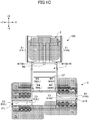
- FIGs. 1A to 1C illustrate an example of an asphalt finisher 100 as an example of a road machine according to an embodiment of the present invention.
- FIG. 1A is a side view of the asphalt finisher 100
- FIGs. 1B and 1C are top views of the asphalt finisher 100.
- the coarsest dot patterns AP in FIG. 1B indicate surfaces of existing pavement or the like
- a cross pattern NP indicates a new pavement.
- the asphalt finisher 100 is primarily constituted with a tractor 1, a hopper 2, and a screed 3.
- the direction of the hopper 2 viewed from the tractor 1 (+X direction) is assumed to be the front
- the direction of the screed 3 viewed from the tractor 1 (-X direction) is assumed to be the rear.
- the tractor 1 is a mechanism for causing the asphalt finisher 100 to travel.
- the tractor 1 rotates rear wheels 5 by using rear-wheel traction motors, and rotates front wheels 6 by using front-wheel traction motors, to move the asphalt finisher 100.
- the rear-wheel traction motors and the front-wheel traction motors receive supply of hydraulic oil from the hydraulic pump, to rotate.
- the rear wheels 5 and the front wheels 6 may be replaced with crawlers.
- a controller 50 is a control device to control the asphalt finisher 100.
- the controller 50 is constituted with an arithmetic/logic processing device including a CPU, a volatile storage device, and a non-volatile storage device, and installed in the tractor 1.
- Various functions of the controller 50 are implemented by the CPU executing programs stored in the non-volatile storage device.
- the hopper 2 is a mechanism for receiving paving materials.
- the hopper 2 is arranged in front of the tractor 1, and includes hopper wings 2W.
- the hopper wings 2W are configured to be capable of being opened and closed in the Y-axis direction (the vehicle-width direction) by hopper cylinders 24.
- the hopper wings 2W include a left hopper wing 2WL and a right hopper wing 2WR
- the hopper cylinders 24 include a left hopper cylinder 24L and a right hopper cylinder 24R.
- the left hopper wing 2WL is configured to be capable of being opened and closed by the left hopper cylinder 24L in the Y-axis direction (the vehicle-width direction)
- the right hopper wing 2WR is configured to be capable of being opened and closed by the right hopper cylinder 24R in the Y-axis direction (the vehicle-width direction).
- the asphalt finisher 100 normally receives a paving material (e.g., an asphalt mixture) from the bed of a dump truck with the hopper wings 2W in a fully opened state.
- FIGs. 1A to 1C illustrate the hopper wings 2W in a fully opened state.
- the paving material in the hopper 2 decreases, the hopper wings 2W are closed, and the paving material remaining near the inner walls of the hopper wings 2W is collected to be gathered at the center of the hopper 2.
- This is to allow a conveyor CV at the center of the hopper 2 to feed the paving material behind the tractor 1.
- the paving material fed behind the tractor 1 is laid and spread by a screw SC in the vehicle-width direction behind the tractor 1 and in front of the screed 3.
- the screw SC is in a state where extension screws are connected on the left and on the right.
- the screed 3 is a mechanism for laying and leveling the pavement material.
- the screed 3 primarily includes front screeds 30 and rear extensible/contractible screeds 31.
- the screed 3 is a floating screed towed by the tractor 1 and coupled with the tractor 1 via leveling arms 3A.
- the screed 3 is moved up and down together with the leveling arms 3A by extension and contraction of screed lift cylinders 25.
- the front screeds 30 include a left front screed 30L and a right front screed 30R
- the rear extensible/contractible screeds 31 include a left rear extensible/contractible screed 31L and a right rear extensible/contractible screed 31R.
- the left rear extensible/contractible screed 31L is extended or contracted in the vehicle-width direction by using a screed extension cylinder 26L
- the right rear extensible/contractible screed 31R is extended or contracted in the vehicle-width direction by using a screed extension cylinder 26R.
- the left front screed 30L is vibrated by a left front vibrator 27L
- the right front screed 30R is vibrated by a right front vibrator 27R
- the left rear extensible/contractible screed 31L is vibrated by a left rear vibrator 28L
- the right rear extensible/contractible screed 31R is vibrated by a right rear vibrator 28R.
- Leveling cylinders 23 are hydraulic cylinders that move the front end parts of the leveling arms 3A up and down to spread and level the asphalt mixture so as to adjust the thickness.
- FIGs. 1A and 1B illustrate the paving material PV to be laid and spread by the screw SC with fine dot patterns.
- the side plates 40 include a right side plate 40R extending forward from the right rear extensible/contractible screed 31R, and a left side plate 40L extending from the left rear extensible/contractible screed 31L.
- Retaining plates 42 are attached to the sides of the tractor 1.
- the retaining plates 42 prevent the paving material PV from spattering forward in the vicinity of the tractor 1 (particularly the rear wheels 5) due to rotation of the screw SC.
- the retaining plates 42 include a right retaining plate 42R attached to the right side surface of the tractor 1, and a left retaining plate 42L attached to the left side surface of the tractor 1.
- the left retaining plate 42L is attached to the left side surface of the tractor 1, to be rotatable (collapsible). The same applies to the right retaining plate 42R.
- Extensible/contractible moldboards 43 are attached to the front of the screed 3.
- the extensible/contractible moldboards 43 constitute a mechanism for adjusting the amount of the paving material PV remaining in front of the screed 3.
- the extensible/contractible moldboards 43 are configured to be extensible and contractible by hydraulic actuators (not illustrated) in accordance with extension and contraction of the rear extensible/contractible screeds 31.
- the paving material PV passes through gaps between the lower ends of the extensible/contractible moldboards 43 and a roadbed RB, to reach a space beneath the screed 3.
- the extensible/contractible moldboards 43 include a right extensible/contractible moldboard 43R attached in front of the right rear extensible/contractible screed 31R, and a left extensible/contractible moldboard 43L attached in front of the left rear extensible/contractible screed 31L.
- the left extensible/contractible moldboard 43L is configured to be adjustable in height in the Z-axis direction, irrespective of the left side plate 40L and the left rear extensible/contractible screed 31L. This is to adjust the amount of paving material remaining in front of the left rear extensible/contractible screed 31L, by moving the left extensible/contractible moldboard 43L up and down. The same applies to the right extensible/contractible moldboard 43R.
- Steps 32 are attached to the rear of the screed 3.
- the steps 32 are footholds that can be used by the operator.
- the steps 32 include a central step 32C attached to the rear of the front screed 30, a right step 32R attached to the rear of the right rear extensible/contractible screed 31R, and a left step 32L attached to the rear of the left rear extensible/contractible screed 31L.
- the asphalt finisher 100 is provided with working lights W1 to W4.
- the working lights W1 to W4 illuminate predetermined spaces by typically using power generated by a generator 12 (an alternator) installed in the tractor 1.
- the generator 12 is driven by an engine 11 as the drive source installed in the tractor 1.
- the working lights W1 to W4 may illuminate predetermined spaces by using power of a storage battery 13 as a battery installed in the tractor 1.
- the working lights W1 to W4 are LED lamps. However, the working lights W1 to W4 may be HID lamps, halogen lamps, or the like.
- the working lights W1 to W4 are configured to be switched between turned-on and turned-off states typically by a switch SW. As illustrated in FIG. 1A , the switch SW is typically included in an operation panel arranged in front of the driver's seat. However, the switch SW may be arranged in another part of the asphalt finisher 100, such as in an operation box SB (see FIG. 2 ) arranged on the screed 3.
- the working lights W1 to W4 may be configured be switched between turned-on and turned-off states by a single switch SW, or may be configured be switched between turned-on and turned-off states by separate switches SW.
- the working lights W1 are headlights illuminating a space in front of (in the traveling direction of) the asphalt finisher 100. As illustrated in FIG. 1B , the working lights W1 include a left headlight W1L arranged at the left end of the front end of the tractor 1, and a right headlight W1R arranged at the right end of the front end of the tractor 1.
- the working light W2 illuminates the interior of the hopper 2. As illustrated in FIG. 1B , the working light W2 is arranged at the center of the front end of the tractor 1, to illuminate an area R1 inside the hopper 2 designated by a coarse dot pattern in FIG. 1C .
- the working lights W3 illuminate spaces in front of the rear extensible/contractible screeds 31. As illustrated in FIGs. 1A and 1B , the working lights W3 are arranged on the sidewalls of the tractor 1. Specifically, the working lights W3 include a left sidelight W3L and a right sidelight W3R.
- the left sidelight W3L illuminates an area R2 in front of the left rear extensible/contractible screed 31L designated by a coarse dot pattern in FIG. 1C .
- the right sidelight W3R illuminates an area R3 in front of the right rear extensible/contractible screed 31R designated by a coarse dot pattern in FIG. 1C .
- the working lights W4 illuminate spaces behind the rear extensible/contractible screeds 31. As illustrated in FIGs. 1A and 1B , the working lights W4 are arranged at the rear end of a canopy CP. Specifically, the working lights W4 include a left backlight W4L and a right backlight W4R.
- the left backlight W4L illuminates an area R4 on the left and behind the left rear extensible/contractible screed 31L designated by a coarse dot pattern in FIG. 1C .
- the right backlight W4R illuminates an area R5 on the right and behind the right rear extensible/contractible screed 31R designated by a coarse dot pattern in FIG. 1C .
- the asphalt finisher 100 is provided with light emitting parts that are arranged consecutively or separately at protruding parts that protrude out of the width of the tractor 1.
- the protruding parts include the hopper 2, the rear extensible/contractible screeds 31, the extensible/contractible moldboards 43, and the like.
- the light emitting parts include attention lights E1 to E3.
- the attention lights E1 to E3 emit light by typically using power generated by the generator 12 (an alternator), similar to the working lights W1 to W4.
- the attention lights E1 to E3 may emit light by using power of the battery 13 installed in the tractor 1.
- the attention lights E1 to E3 are LED ribbon lights in the present embodiment. However, the attention lights E1 to E3 may be filament lamps, xenon lamps, or the like. The attention lights E1 to E3 are configured to be typically turned on when the working lights W1 to W4 are turned on. In the present embodiment, the attention lights E1 to E3 are configured to be turned on when the working lights W1 to W4 are turned on by the switch SW, and to be turned off when the working lights W1 to W4 are turned off by the switch SW. However, the attention lights E1 to E3 may be switched between on and off irrespective of the working lights W1 to W4. For example, the attention lights E1 to E3 may be configured to be automatically turned on when the surroundings are determined to become dark based on the output of an irradiation sensor (not illustrated).
- Each of the attention lights E1 to E3 may be configured to emit light in any lighting/blinking mode such as continuous lighting, simultaneous blinking, sequential blinking, or the like.
- Continuous lighting designates a lighting mode, for example, in which all of the multiple LEDs constituting the attention lights E2 are lit continuously.
- Simultaneous blinking designates a blinking mode, for example, in which each of the multiple LEDs constituting the attention lights E2 blinks at the same timing.
- Sequential blinking designates a blinking mode in which each of the multiple LEDs constituting the attention lights E2 blinks at a timing different from one another and in a predetermined order.
- a lighting/blinking mode may be configured to vary depending on the state of protrusion, the protrusion speed, or the like of the protruding parts.
- the protrusion speed includes, for example, the opening/closing speed of the hopper 2, the extension and contraction speed of the rear extensible/contractible screeds 31, the extension and contraction speed of the extensible/contractible moldboards 43, and the like.
- the attention lights E1 are light emitting parts that increase the visibility of the hopper wings 2W as the protruding parts. As illustrated in FIG. 1B , the attention lights E1 include a left ribbon light E1L arranged along the end surface at the edge of the left hopper wing 2WL, and a right ribbon light E1R arranged along the end surface at the edge of the right hopper wing 2WR. The left ribbon light E1L is connected to the controller 50 via a signal line S1L, and the right ribbon light E1R is connected to the controller 50 via a signal line S1R. Note that the attention lights E1 may be arranged at portions of the hopper wings 2W close to the edges of the outer walls.
- the driver of a dump truck supplying the paving material to the hopper 2 can easily recognize an opening/closing state of the hopper wings 2W when moving backward toward the asphalt finisher 100 during night work. Also, the driver of a vehicle driving on an existing road adjacent to the road under construction can easily recognize an opening/closing state of the hopper wings 2W, when approaching the asphalt finisher 100 from the front side (+X side) while driving in the night.
- the attention lights E2 are light emitting parts that increase the visibility from the front side of the rear extensible/contractible screeds 31 as the protruding parts. As illustrated in FIG. 1B , the attention lights E2 include a left front ribbon light E2L arranged along the front edge of the top surface of the left rear extensible/contractible screed 31L, and a right front ribbon light E2R arranged along the front edge of the top surface of the right rear extensible/contractible screed 31R.
- the left front ribbon light E2L is connected to the controller 50 via a signal line S2L
- the right front ribbon light E2R is connected to the controller 50 via a signal line S2R.
- the left front ribbon light E2L illuminates an area R2A in front of the left rear extensible/contractible screed 31L designated by a fine dot pattern in FIG. 1C .
- the area R2A is part of the area R2.
- the right front ribbon light E2R illuminates an area R3A in front of the right rear extensible/contractible screed 31R designated by a fine dot pattern in FIG. 1C .
- the area R3A is part of the area R3.
- the driver of a vehicle driving on an existing road adjacent to the road under construction can easily recognize the state of extension and contraction of the rear extensible/contractible screeds 31, when approaching the asphalt finisher 100 from the front side (+X side) while driving in the night.
- the attention lights E2 may also function as auxiliary lights to assist illumination by the working lights W3.
- the attention lights E3 are light emitting parts that increase the visibility from behind the rear extensible/contractible screeds 31 as the protruding parts. As illustrated in FIG. 1B , the attention lights E3 include a left rear ribbon light E3L arranged along the rear edge of the top surface of the left rear extensible/contractible screed 31L, and a right rear ribbon light E3R arranged along the rear edge of the top surface of the right rear extensible/contractible screed 31R.
- the left rear ribbon light E3L is connected to the controller 50 via a signal line S3L
- the right rear ribbon light E3R is connected to the controller 50 via a signal line S3R.
- the left rear ribbon light E3L illuminates an area R4A behind the left rear extensible/contractible screed 31L designated by a fine dot pattern in FIG. 1C .
- the area R4A is part of the area R4.
- the right rear ribbon light E3R illuminates an area R5A behind the right rear extensible/contractible screed 31R designated by a fine dot pattern in FIG. 1C .
- the area R5A is part of the area R5.
- the driver of a vehicle driving on an existing road adjacent to the road under construction can easily recognize the state of extension and contraction of the rear extensible/contractible screeds 31, when approaching the asphalt finisher 100 from behind (-X side) while driving in the night.
- the attention lights E3 may also function as auxiliary lights to assist illumination by the working lights W4.
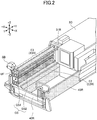
- FIG. 2 is a perspective view of the right rear extensible/contractible screed 31R.
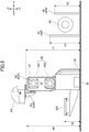
- FIG. 3 is a side view of the right rear extensible/contractible screed 31R as viewed from the -Y side (right side) of the right rear extensible/contractible screed 31R.
- FIG. 3 omits illustration of the right side plate 40R for the sake of clarification.
- the following description of the right rear extensible/contractible screed 31R also applies to the left rear extensible/contractible screed 31L.
- the right rear extensible/contractible screed 31R is primarily constituted with a shaft cover UF, guide shafts GS, a strike-off plate 33, and a screed plate 35. Further, as illustrated in FIG. 3 , the -Z side part (bottom part) of the right rear extensible/contractible screed 31R is primarily constituted with the strike-off plate 33 and the screed plate 35.
- the shaft cover UF is a member that constitutes the top end of the right rear extensible/contractible screed 31R.
- the shaft cover UF is formed to be virtually a rectangular parallelepiped, and configured to cover the top of the guide shafts GS.
- the guide shafts GS are configured to guide extension and contraction of the right rear extensible/contractible screed 31R.
- the guide shafts GS include an upper guide shaft GS1 and a lower guide shaft GS2.
- the strike-off plate 33 is a member to swallow (push) the paving material PV, that has been laid and spread by the screw SC and adjusted in quantity by the right extensible/contractible moldboard 43R, under the right rear extensible/contractible screed 31R.
- the strike-off plate 33 extends over the entire span of the right rear extensible/contractible screed 31R in the Y-axis direction (the vehicle-width direction), and has an inclined surface inclined with respect to the -Z side surface (bottom surface) of the screed plate 35 provided at the lower part.
- the inclined surface of the strike-off plate 33 and the bottom surface of the screed plate 35 form a swallowing angle of the paving material.
- the screed plate 35 is a member constituting the bottom part of the rear extensible/contractible screed 31 vibrated by a vibrator, to compact the paving material PV swallowed through a space between the roadbed RB and the strike-off plate 33.
- the screed plate 35 extends over the entire span of the rear extensible/contractible screed 31 in the vehicle-width direction.
- the operation box SB is a device used by the operator working behind the asphalt finisher 100 to operate the asphalt finisher 100.
- the operation box SB includes a lever switch, a push switch, a monitor, and the like (not illustrated), and is configured to allow the operator to adjust the state of extension and contraction of the leveling cylinders 23, the state of extension and contraction of the rear extensible/contractible screeds 31, and the spreading speed (operating speed) of the conveyor CV.
- the right front ribbon light E2R is arranged along the extension/contraction direction (Y-axis direction) at the front edge (the edge on the +X side) of the top surface of the shaft cover UF being virtually a rectangular parallelepiped constituting the right rear extensible/contractible screed 31R.
- the right front ribbon light E2R has a configuration in which 15 LEDs are separately arranged at predetermined equidistant intervals.
- the LEDs have the same size.
- the LEDs may be arranged separately at non-equidistant intervals, or may be arranged consecutively so that the LEDs are contiguous to one another in the extension/contraction direction.
- the LEDs may have different sizes.
- the right front ribbon light E2R may be constituted with a single elongated LED. The same applies to the left front ribbon light E2L.
- the right front ribbon light E2R may be configured to emit light in any luminescent color.
- the right front ribbon light E2R is configured to emit light in the same color as the right sidelight W3R.
- the right front ribbon light E2R may be configured to emit light in a luminescent color different from that of the right sidelight W3R. The same applies to the left front ribbon light E2L.
- the right front ribbon light E2R may be arranged on the front surface of the shaft cover UF (surface on the +X side), or may be arranged on the front edge of the lower surface of the shaft cover UF. Also, the right front ribbon light E2R may be arranged on another member constituting the right rear extensible/contractible screed 31R (desirably an elongated member extending in the extension/contraction direction). The same applies to the left front ribbon light E2L.
- the right front ribbon light E2R is desirably arranged at a relatively high position so as not to be hidden behind other members when viewed by the operator and the like from the front side (+X side).
- a height H1 of the right front ribbon light E2R from the ground is higher than a height H2 of the right retaining plate 42R from the ground, and higher than a height H3 of the right extensible/contractible moldboard 43R from the ground. The same applies to the left front ribbon light E2L.
- the right rear ribbon light E3R is arranged along the extension/contraction direction (Y-axis direction) at the rear edge (the edge on the -X side) of the top surface of the shaft cover UF of the right rear extensible/contractible screed 31R.
- the right rear ribbon light E3R has a configuration in which 15 LEDs are separately arranged at predetermined equidistant intervals.
- the LEDs have the same size.
- the LEDs may be arranged separately at non-equidistant intervals, or may be arranged consecutively so that the LEDs are contiguous to one another in the extension/contraction direction.
- the LEDs may have different sizes.
- the right rear ribbon light E3R may be constituted with a single elongated LED. The same applies to the left rear ribbon light E3L.
- the right rear ribbon light E3R may be configured to emit light in any luminescent color.
- the right rear ribbon light E3R is configured to emit light of the same color as the right backlight W4R.
- the right rear ribbon light E3R may be configured to emit light in a luminescent color different from that of the right backlight W4R. The same applies to the left rear ribbon light E3L.
- the right rear ribbon light E3R may be arranged on the rear surface of the shaft cover UF (surface on the -X side), or may be arranged on the rear edge of the lower surface of the shaft cover UF. Also, the right rear ribbon light E3R may be arranged on another member constituting the right rear extensible/contractible screed 31R (desirably an elongated member extending in the extension/contraction direction). The same applies to the left rear ribbon light E3L.
- the right rear ribbon light E3R is arranged at a relatively high position so as not to be hidden behind other members when viewed from the rear side (+X side).
- a height H4 of the right rear ribbon light E3R from the ground is higher than a height H5 of the right step 32R from the ground. The same applies to the left rear ribbon light E3L.
- both the right front ribbon light E2R and the right rear ribbon light E3R are attached to the right rear extensible/contractible screed 31R, so as not to hinder the right rear extensible/contractible screed 31R from being housed in a screed cover 3C. Therefore, in the present embodiment, the right front ribbon light E2R and the right rear ribbon light E3R are configured to be housed in the screed cover 3C together with the right rear extensible/contractible screed 31R. In other words, the attention lights E3 as the light emitting parts are configured to be housed in the screed cover 3C when the rear extensible/contractible screeds 31 are in a contracted state.
- the right front ribbon light E2R and the right rear ribbon light E3R may be configured to be easily attachable to and detachable from the right rear extensible/contractible screed 31R.
- the LEDs may be configured to be easily attachable and detachable.
- the right front ribbon light E2R and the right rear ribbon light E3R may be detached from the right rear extensible/contractible screed 31R when the right rear extensible/contractible screed 31R is to be housed in the screed cover 3C.
- the asphalt finisher 100 includes the tractor 1, the protruding parts protruding out of the width of the tractor 1, and the light emitting parts arranged consecutively or separately on the protruding parts.
- the protruding parts include, for example, the hopper 2, the rear extensible/contractible screeds 31, the extensible/contractible moldboards 43, and the like.
- the light emitting parts include, for example, the attention lights E1 to E3 and the like.
- the asphalt finisher 100 can improve the visibility of the parts protruding out of the width of the tractor 1. Therefore, a person viewing the asphalt finisher 100 from the outside can easily recognize the presence of the protruding parts, such as the hopper 2, the rear extensible/contractible screeds 31, the extensible/contractible moldboards 43, and the like even in the night. As a result, the asphalt finisher 100 can increase the safety of the work.
- the attention lights E2 and E3 as the light emitting parts are desirably arranged consecutively or separately along the extension/contraction direction of the rear extensible/contractible screeds 31.
- a person viewing the asphalt finisher 100 from the outside can easily recognize that the rear extensible/contractible screeds 31 extend continuously in the vehicle-width direction, namely, the rear extensible/contractible screeds 31 are connected to the main body of the asphalt finisher 100. Therefore, this configuration can prevent, for example, a person viewing the asphalt finisher 100 from the outside from erroneously recognizing that gaps (spaces) are present between the main body of the asphalt finisher 100 and the ends of the rear extensible/contractible screeds 31.
- the protruding parts may be the rear extensible/contractible screeds 31 that are extendable and contractible in the vehicle-width direction.
- the attention lights E2 and E3 as the light emitting parts may be arranged to illuminate spaces in front of and behind the rear extensible/contractible screeds 31.
- the asphalt finisher 100 can illuminate the spaces in front of and behind the rear extensible/contractible screeds 31 more brightly than in the case of illuminating only with the working lights W3 and W4.
- the operator working around the asphalt finisher 100 can easily confirm the amount of the paving material PV carried around the screw SC even in the night.
- the protruding parts may be the extensible/contractible moldboards 43 that are extendable and contractible in the vehicle-width direction.
- the light emitting parts may be arranged consecutively or separately on the extensible/contractible moldboards 43 along the extension/contraction direction of the extensible/contractible moldboards 43. With this configuration, the asphalt finisher 100 can improve the visibility of the extensible/contractible moldboards 43.
- the protruding parts may be the hopper 2 that can be opened and closed in the vehicle-width direction.
- the protruding parts may be the hopper wings 2W that can be opened and closed in the vehicle-width direction.
- the attention lights E1 as the light emitting parts may be arranged consecutively or separately along the end surfaces of the hopper wings 2W. With this configuration, the asphalt finisher 100 can improve the visibility of the hopper 2.
- the asphalt finisher 100 is typically provided with the working lights W1 to W4. Therefore, the attention lights E1 to E3 as the light emitting parts may be configured to be turned on when the working lights W1 to W4 are turned on. With this configuration, the operator can securely turn on the attention lights E1 to E3 when turning on the working lights W1 to W4. Therefore, the attention lights E1 to E3 can be prevented from being left turned off when night work starts.
- the light emitting parts include the attention lights E1 arranged along the end surfaces of the edges of the hopper wings 2W, the attention lights E2 arranged along the front edges of the top surfaces of the rear extensible/contractible screeds 31, and the attention lights E3 arranged along the rear edges of the top surfaces of the rear extensible/contractible screeds 31.
- the light emitting parts may include attention lights arranged at the front and the rear of the screed cover 3C.
- the light emitting parts may include an attention light arranged along the front edge of the top surface of the screed cover 3C, and an attention light arranged along the rear edge of the top surface of the screed cover 3C.
Landscapes
- Engineering & Computer Science (AREA)
- Mechanical Engineering (AREA)
- Architecture (AREA)
- Civil Engineering (AREA)
- Structural Engineering (AREA)
- Road Paving Machines (AREA)
Applications Claiming Priority (2)
| Application Number | Priority Date | Filing Date | Title |
|---|---|---|---|
| JP2018146897 | 2018-08-03 | ||
| PCT/JP2019/030410 WO2020027313A1 (ja) | 2018-08-03 | 2019-08-02 | アスファルトフィニッシャ |
Publications (2)
| Publication Number | Publication Date |
|---|---|
| EP3832018A1 true EP3832018A1 (de) | 2021-06-09 |
| EP3832018A4 EP3832018A4 (de) | 2021-09-15 |
Family
ID=69231861
Family Applications (1)
| Application Number | Title | Priority Date | Filing Date |
|---|---|---|---|
| EP19844096.8A Pending EP3832018A4 (de) | 2018-08-03 | 2019-08-02 | Asphaltfertiger |
Country Status (4)
| Country | Link |
|---|---|
| EP (1) | EP3832018A4 (de) |
| JP (1) | JPWO2020027313A1 (de) |
| CN (1) | CN112368446A (de) |
| WO (1) | WO2020027313A1 (de) |
Family Cites Families (20)
| Publication number | Priority date | Publication date | Assignee | Title |
|---|---|---|---|---|
| JPH0743133Y2 (ja) * | 1991-04-17 | 1995-10-04 | 株式会社新潟鉄工所 | アスファルトフィニッシャにおけるダンプカーの誘導装置 |
| US5352063A (en) * | 1992-09-30 | 1994-10-04 | Allen Engineering Corporation | Polymer concrete paving machine |
| JPH0660608U (ja) * | 1993-02-03 | 1994-08-23 | 範多機械株式会社 | アスファルトフィニッシャのホッパー |
| JP2505210Y2 (ja) * | 1993-04-09 | 1996-07-24 | 建設省東北地方建設局長 | 舗装作業車の自動操向装置 |
| JPH074166U (ja) * | 1993-06-17 | 1995-01-20 | 株式会社アイチコーポレーション | 作業車の作業表示装置 |
| JP2001138803A (ja) * | 1999-11-12 | 2001-05-22 | Shin Caterpillar Mitsubishi Ltd | 作業装置の車幅灯取付構造 |
| JP2002160575A (ja) * | 2000-11-28 | 2002-06-04 | Shinmeiwa Auto Engineering Ltd | 作業車両の警報装置 |
| JP2004116448A (ja) | 2002-09-27 | 2004-04-15 | Shin Caterpillar Mitsubishi Ltd | アスファルトフィニッシャのエンジン制御装置 |
| JP2004143894A (ja) * | 2002-10-21 | 2004-05-20 | Seki Kogyo Kk | 除雪用ブレードの車幅表示灯 |
| JP2006062545A (ja) * | 2004-08-27 | 2006-03-09 | Souji Kobayashi | 自動車のドア開放時の衝突事故防止装置 |
| JP4450387B2 (ja) * | 2005-04-12 | 2010-04-14 | キャタピラージャパン株式会社 | 建設機械における照明装置の取り付け構造。 |
| JP5637933B2 (ja) * | 2011-05-20 | 2014-12-10 | 住友建機株式会社 | スクリード装置の伸縮モールドボード上下調整機構 |
| PL2578748T3 (pl) * | 2011-10-04 | 2019-01-31 | Joseph Vögele AG | Zewnętrzne stanowisko sterowania dla maszyny budowlanej |
| DE102015008315A1 (de) * | 2015-06-30 | 2017-01-05 | Dynapac Gmbh | Einbaubohle und Straßenfertiger |
| EP3214223B1 (de) * | 2016-03-04 | 2019-05-08 | Joseph Vögele AG | Strassenfertiger mit seitlicher bedieneinheit |
| CN205951811U (zh) * | 2016-08-19 | 2017-02-15 | 南京快联路桥建设工程有限公司 | 摊铺机照明结构 |
| JP2018146897A (ja) | 2017-03-08 | 2018-09-20 | 株式会社リコー | 電源装置及び画像形成装置 |
| CN206800131U (zh) * | 2017-06-08 | 2017-12-26 | 路敏 | 沥青路面热再生摊铺机 |
| JP2019002205A (ja) * | 2017-06-15 | 2019-01-10 | 範多機械株式会社 | アスファルトフィニッシャ |
| CN207619871U (zh) * | 2017-12-12 | 2018-07-17 | 漆亮 | 一种太阳能建筑施工警示装置 |
-
2019
- 2019-08-02 JP JP2020534765A patent/JPWO2020027313A1/ja active Pending
- 2019-08-02 WO PCT/JP2019/030410 patent/WO2020027313A1/ja unknown
- 2019-08-02 CN CN201980044327.XA patent/CN112368446A/zh active Pending
- 2019-08-02 EP EP19844096.8A patent/EP3832018A4/de active Pending
Also Published As
| Publication number | Publication date |
|---|---|
| WO2020027313A1 (ja) | 2020-02-06 |
| EP3832018A4 (de) | 2021-09-15 |
| CN112368446A (zh) | 2021-02-12 |
| JPWO2020027313A1 (ja) | 2021-08-10 |
Similar Documents
| Publication | Publication Date | Title |
|---|---|---|
| US5846022A (en) | Apparatus for laying pavement layers | |
| CN103031800B (zh) | 用于建筑机械的外部控制台 | |
| EP3237253B1 (de) | Materialtransportfahrzeug mit einer expandierbaren lastwagenlademulde | |
| CN108699784A (zh) | 具有作为导航辅助的投影仪的筑路机 | |
| EP3421669B1 (de) | Arbeitsmaschine | |
| CN102162218B (zh) | 带旋转铣刨滚的路基修筑机 | |
| EP0957204A1 (de) | Strassenfertiger und Beschicker hierfür | |
| EP3832018A1 (de) | Asphaltfertiger | |
| DE102020110093A1 (de) | Beleuchtungs-steuersystem für mobile maschinen | |
| US5531542A (en) | Dual auger/conveyor drive for a paver | |
| CN111827053A (zh) | 压实机筒边缘指示装置 | |
| US10233599B2 (en) | Milling machine | |
| CN205474744U (zh) | 一种沥青混合料摊铺机 | |
| JP2018044281A (ja) | 路面切削車両の安全監視装置 | |
| US3330188A (en) | Road widener | |
| CN105431329B (zh) | 用于运载车辆的可调节照明系统及其控制方法 | |
| KR101911921B1 (ko) | 교통 신호 기능을 갖는 분리대 | |
| RU2465393C1 (ru) | Отвал для уборки снега | |
| EP0157620A1 (de) | Gehweg-Fertigung | |
| EP2340964B1 (de) | Anhänger und Verfahren für Dosierung Gleitschutzmaterial | |
| WO2023190355A1 (ja) | 道路機械 | |
| CN215752142U (zh) | 工程机械 | |
| RU129512U1 (ru) | Самоходный дорожно-строительный агрегат | |
| JP2023151437A (ja) | 道路機械 | |
| JP2010100999A (ja) | アスファルトフィニッシャにおけるレーン引きユニットの取付装置 |
Legal Events
| Date | Code | Title | Description |
|---|---|---|---|
| STAA | Information on the status of an ep patent application or granted ep patent |
Free format text: STATUS: THE INTERNATIONAL PUBLICATION HAS BEEN MADE |
|
| PUAI | Public reference made under article 153(3) epc to a published international application that has entered the european phase |
Free format text: ORIGINAL CODE: 0009012 |
|
| STAA | Information on the status of an ep patent application or granted ep patent |
Free format text: STATUS: REQUEST FOR EXAMINATION WAS MADE |
|
| 17P | Request for examination filed |
Effective date: 20210301 |
|
| AK | Designated contracting states |
Kind code of ref document: A1 Designated state(s): AL AT BE BG CH CY CZ DE DK EE ES FI FR GB GR HR HU IE IS IT LI LT LU LV MC MK MT NL NO PL PT RO RS SE SI SK SM TR |
|
| STAA | Information on the status of an ep patent application or granted ep patent |
Free format text: STATUS: EXAMINATION IS IN PROGRESS |
|
| A4 | Supplementary search report drawn up and despatched |
Effective date: 20210816 |
|
| RIC1 | Information provided on ipc code assigned before grant |
Ipc: F21S 41/00 20180101ALI20210810BHEP Ipc: B60Q 1/02 20060101ALI20210810BHEP Ipc: E01C 19/48 20060101AFI20210810BHEP |
|
| 17Q | First examination report despatched |
Effective date: 20210827 |
|
| DAV | Request for validation of the european patent (deleted) | ||
| DAX | Request for extension of the european patent (deleted) | ||
| GRAP | Despatch of communication of intention to grant a patent |
Free format text: ORIGINAL CODE: EPIDOSNIGR1 |
|
| STAA | Information on the status of an ep patent application or granted ep patent |
Free format text: STATUS: GRANT OF PATENT IS INTENDED |
|
| INTG | Intention to grant announced |
Effective date: 20240723 |