EP3831278A1 - Anordnung und verfahren zum darstellen von medizinischen alarmen - Google Patents
Anordnung und verfahren zum darstellen von medizinischen alarmen Download PDFInfo
- Publication number
- EP3831278A1 EP3831278A1 EP20208612.0A EP20208612A EP3831278A1 EP 3831278 A1 EP3831278 A1 EP 3831278A1 EP 20208612 A EP20208612 A EP 20208612A EP 3831278 A1 EP3831278 A1 EP 3831278A1
- Authority
- EP
- European Patent Office
- Prior art keywords
- alarm
- sequence
- time
- signal processing
- signal
- Prior art date
- Legal status (The legal status is an assumption and is not a legal conclusion. Google has not performed a legal analysis and makes no representation as to the accuracy of the status listed.)
- Pending
Links
Images


Classifications
-
- G—PHYSICS
- G16—INFORMATION AND COMMUNICATION TECHNOLOGY [ICT] SPECIALLY ADAPTED FOR SPECIFIC APPLICATION FIELDS
- G16H—HEALTHCARE INFORMATICS, i.e. INFORMATION AND COMMUNICATION TECHNOLOGY [ICT] SPECIALLY ADAPTED FOR THE HANDLING OR PROCESSING OF MEDICAL OR HEALTHCARE DATA
- G16H40/00—ICT specially adapted for the management or administration of healthcare resources or facilities; ICT specially adapted for the management or operation of medical equipment or devices
- G16H40/40—ICT specially adapted for the management or administration of healthcare resources or facilities; ICT specially adapted for the management or operation of medical equipment or devices for the management of medical equipment or devices, e.g. scheduling maintenance or upgrades
-
- G—PHYSICS
- G08—SIGNALLING
- G08B—SIGNALLING OR CALLING SYSTEMS; ORDER TELEGRAPHS; ALARM SYSTEMS
- G08B21/00—Alarms responsive to a single specified undesired or abnormal condition and not otherwise provided for
- G08B21/02—Alarms for ensuring the safety of persons
-
- A—HUMAN NECESSITIES
- A61—MEDICAL OR VETERINARY SCIENCE; HYGIENE
- A61B—DIAGNOSIS; SURGERY; IDENTIFICATION
- A61B5/00—Measuring for diagnostic purposes; Identification of persons
- A61B5/02—Detecting, measuring or recording pulse, heart rate, blood pressure or blood flow; Combined pulse/heart-rate/blood pressure determination; Evaluating a cardiovascular condition not otherwise provided for, e.g. using combinations of techniques provided for in this group with electrocardiography or electroauscultation; Heart catheters for measuring blood pressure
- A61B5/024—Detecting, measuring or recording pulse rate or heart rate
-
- A—HUMAN NECESSITIES
- A61—MEDICAL OR VETERINARY SCIENCE; HYGIENE
- A61B—DIAGNOSIS; SURGERY; IDENTIFICATION
- A61B5/00—Measuring for diagnostic purposes; Identification of persons
- A61B5/08—Detecting, measuring or recording devices for evaluating the respiratory organs
- A61B5/0816—Measuring devices for examining respiratory frequency
-
- A—HUMAN NECESSITIES
- A61—MEDICAL OR VETERINARY SCIENCE; HYGIENE
- A61B—DIAGNOSIS; SURGERY; IDENTIFICATION
- A61B5/00—Measuring for diagnostic purposes; Identification of persons
- A61B5/08—Detecting, measuring or recording devices for evaluating the respiratory organs
- A61B5/087—Measuring breath flow
-
- A—HUMAN NECESSITIES
- A61—MEDICAL OR VETERINARY SCIENCE; HYGIENE
- A61B—DIAGNOSIS; SURGERY; IDENTIFICATION
- A61B5/00—Measuring for diagnostic purposes; Identification of persons
- A61B5/08—Detecting, measuring or recording devices for evaluating the respiratory organs
- A61B5/091—Measuring volume of inspired or expired gases, e.g. to determine lung capacity
-
- A—HUMAN NECESSITIES
- A61—MEDICAL OR VETERINARY SCIENCE; HYGIENE
- A61B—DIAGNOSIS; SURGERY; IDENTIFICATION
- A61B5/00—Measuring for diagnostic purposes; Identification of persons
- A61B5/103—Detecting, measuring or recording devices for testing the shape, pattern, colour, size or movement of the body or parts thereof, for diagnostic purposes
- A61B5/11—Measuring movement of the entire body or parts thereof, e.g. head or hand tremor, mobility of a limb
- A61B5/1126—Measuring movement of the entire body or parts thereof, e.g. head or hand tremor, mobility of a limb using a particular sensing technique
-
- A—HUMAN NECESSITIES
- A61—MEDICAL OR VETERINARY SCIENCE; HYGIENE
- A61B—DIAGNOSIS; SURGERY; IDENTIFICATION
- A61B5/00—Measuring for diagnostic purposes; Identification of persons
- A61B5/103—Detecting, measuring or recording devices for testing the shape, pattern, colour, size or movement of the body or parts thereof, for diagnostic purposes
- A61B5/11—Measuring movement of the entire body or parts thereof, e.g. head or hand tremor, mobility of a limb
- A61B5/113—Measuring movement of the entire body or parts thereof, e.g. head or hand tremor, mobility of a limb occurring during breathing
-
- A—HUMAN NECESSITIES
- A61—MEDICAL OR VETERINARY SCIENCE; HYGIENE
- A61B—DIAGNOSIS; SURGERY; IDENTIFICATION
- A61B5/00—Measuring for diagnostic purposes; Identification of persons
- A61B5/145—Measuring characteristics of blood in vivo, e.g. gas concentration, pH value; Measuring characteristics of body fluids or tissues, e.g. interstitial fluid, cerebral tissue
- A61B5/14542—Measuring characteristics of blood in vivo, e.g. gas concentration, pH value; Measuring characteristics of body fluids or tissues, e.g. interstitial fluid, cerebral tissue for measuring blood gases
-
- A—HUMAN NECESSITIES
- A61—MEDICAL OR VETERINARY SCIENCE; HYGIENE
- A61B—DIAGNOSIS; SURGERY; IDENTIFICATION
- A61B5/00—Measuring for diagnostic purposes; Identification of persons
- A61B5/72—Signal processing specially adapted for physiological signals or for diagnostic purposes
-
- A—HUMAN NECESSITIES
- A61—MEDICAL OR VETERINARY SCIENCE; HYGIENE
- A61B—DIAGNOSIS; SURGERY; IDENTIFICATION
- A61B5/00—Measuring for diagnostic purposes; Identification of persons
- A61B5/74—Details of notification to user or communication with user or patient ; user input means
- A61B5/742—Details of notification to user or communication with user or patient ; user input means using visual displays
-
- A—HUMAN NECESSITIES
- A61—MEDICAL OR VETERINARY SCIENCE; HYGIENE
- A61B—DIAGNOSIS; SURGERY; IDENTIFICATION
- A61B5/00—Measuring for diagnostic purposes; Identification of persons
- A61B5/74—Details of notification to user or communication with user or patient ; user input means
- A61B5/746—Alarms related to a physiological condition, e.g. details of setting alarm thresholds or avoiding false alarms
-
- A—HUMAN NECESSITIES
- A61—MEDICAL OR VETERINARY SCIENCE; HYGIENE
- A61B—DIAGNOSIS; SURGERY; IDENTIFICATION
- A61B5/00—Measuring for diagnostic purposes; Identification of persons
- A61B5/74—Details of notification to user or communication with user or patient ; user input means
- A61B5/7475—User input or interface means, e.g. keyboard, pointing device, joystick
-
- A—HUMAN NECESSITIES
- A61—MEDICAL OR VETERINARY SCIENCE; HYGIENE
- A61M—DEVICES FOR INTRODUCING MEDIA INTO, OR ONTO, THE BODY; DEVICES FOR TRANSDUCING BODY MEDIA OR FOR TAKING MEDIA FROM THE BODY; DEVICES FOR PRODUCING OR ENDING SLEEP OR STUPOR
- A61M16/00—Devices for influencing the respiratory system of patients by gas treatment, e.g. mouth-to-mouth respiration; Tracheal tubes
- A61M16/0051—Devices for influencing the respiratory system of patients by gas treatment, e.g. mouth-to-mouth respiration; Tracheal tubes with alarm devices
-
- A—HUMAN NECESSITIES
- A61—MEDICAL OR VETERINARY SCIENCE; HYGIENE
- A61M—DEVICES FOR INTRODUCING MEDIA INTO, OR ONTO, THE BODY; DEVICES FOR TRANSDUCING BODY MEDIA OR FOR TAKING MEDIA FROM THE BODY; DEVICES FOR PRODUCING OR ENDING SLEEP OR STUPOR
- A61M16/00—Devices for influencing the respiratory system of patients by gas treatment, e.g. mouth-to-mouth respiration; Tracheal tubes
- A61M16/01—Devices for influencing the respiratory system of patients by gas treatment, e.g. mouth-to-mouth respiration; Tracheal tubes specially adapted for anaesthetising
-
- G—PHYSICS
- G08—SIGNALLING
- G08B—SIGNALLING OR CALLING SYSTEMS; ORDER TELEGRAPHS; ALARM SYSTEMS
- G08B21/00—Alarms responsive to a single specified undesired or abnormal condition and not otherwise provided for
- G08B21/18—Status alarms
- G08B21/182—Level alarms, e.g. alarms responsive to variables exceeding a threshold
-
- G—PHYSICS
- G08—SIGNALLING
- G08B—SIGNALLING OR CALLING SYSTEMS; ORDER TELEGRAPHS; ALARM SYSTEMS
- G08B5/00—Visible signalling systems, e.g. personal calling systems, remote indication of seats occupied
- G08B5/22—Visible signalling systems, e.g. personal calling systems, remote indication of seats occupied using electric transmission; using electromagnetic transmission
Definitions
- the invention relates to an arrangement with a medical device, a signal processing unit, an output unit and preferably an input unit, the signal processing unit receiving measured values from at least one patient sensor, detecting alarms and controlling the output unit, the controlled output unit being able to visually output information to a user and wherein the optional input unit is capable of capturing user inputs.
- the invention also relates to a method for displaying medical information using such an arrangement.
- a ventilation system with a supply device and a display device 15 is described.
- a producer marker 23 is displayed along a time axis 19 for successive points in time.
- the producer marker 23 is positioned such that the ratio of its distance from the time axis 19 to the distance between the time axis and a boundary line 21 is equal to the ratio of a first producer parameter to the sum of the first producer parameter and a second producer parameter minus a first consumer parameter.
- US 2014/0 275 819 A1 shows a patient monitoring device (medical monitoring device) with several sensors, each of which monitors a physiological parameter of a patient.
- a signal processing unit (processing circuitry 204) receives measured values from the sensors and controls an output unit (device 200 with displays 202) and an alarm unit (alarm mechanism 216).
- the respective temporal progression of various signals, each of which is physiological, are displayed on the screen Describe the patient's parameters and, if values deviate from a normal value, alarm marker shadings and alarm marker lines are shown at the respective points in time. A user can move the displayed time period and enlarge a display.
- Devices and methods to monitor a patient (patient monitoring) and to display medical alarms are also in US 2003/0 200 117 A1 , US 2005/038 332 A1 , US 2008/078 390 A1 , US 2011/0 138 311 A1 , US 2013/0 246 089 A1 , US 2018/0 277 243 A1 and US 2018/0 300 919 A1 described.
- the invention is based on the object of providing an arrangement comprising a medical device, an output unit and a signal processing unit as well as a method for displaying alarms on an output unit, it being possible to display a large number of alarms ergonomically even when a display area of the Output unit is small compared to the number of detected alarms.
- the arrangement according to the invention comprises a medical device, in particular a ventilator or an anesthesia device.
- the medical device comprises at least one patient sensor, preferably several patient sensors, or can be connected at least temporarily to at least one patient sensor.
- the or each patient sensor is able to measure at least one variable that occurs on or in a patient, preferably at least one vital parameter of the patient.
- the arrangement according to the invention further comprises an output unit which is able to visually output information to a user, for example on a screen. Furthermore, the arrangement comprises a data-processing signal processing unit which is able to control the output unit and which is preferably able to detect a user input.
- the signal processing unit is able to receive measured values which the or at least one patient sensor has generated. In that the signal processing unit evaluates received measured values, the signal processing unit is able to generate at least one signal. This signal correlates with a variable over time that occurs on or in the patient, for example with a variable for spontaneous breathing or for the heartbeat or for the oxygen content in the blood or the CO2 content in the exhaled breath of the patient.
- the signal processing unit can preferably generate a plurality of signals and, for this purpose, preferably process measured values from different patient sensors.
- At least one alarm criterion is specified.
- the or each predetermined alarm criterion relates to the or at least one signal which the signal processing unit is able to derive from measured values of the or at least one patient sensor.
- the signal processing unit can automatically decide whether the or at least one predetermined alarm criterion is met. For this decision, the signal processing unit is able to evaluate the or at least one generated signal. It is possible that different predefined alarm criteria relate to different signals or also to the same signal
- the signal processing unit has decided that the alarm criterion or an alarm criterion is met, it has automatically detected an alarm.
- An alarm is present if at least one signal fulfills a predefined alarm criterion at a certain point in time. The signal processing unit is able to detect this alarm as well as the point in time at which the alarm criterion was met and thus the alarm occurred. The same alarm criterion can be fulfilled several times, namely at different times. At least two different alarm criteria can be specified for the same signal and can therefore be met at the same time or at different times. Every time the or an alarm criterion is met and this event is detected, the signal processing unit has again detected an alarm. Each alarm criterion defines an alarm type. Each alarm belongs to one alarm type. It is possible that the same alarm criterion is met several times, namely at different times. Then several similar types of alarms occurred one after the other.
- the overall alarm sequence shows a chronological sequence of alarms that were detected in a predetermined overall period.
- the overall alarm sequence preferably shows all alarms that were detected in the overall period, preferably graphically.
- the alarm reference section shows a chronological sequence of alarms that were detected in a predetermined and preferably changeable reference time window.
- This reference time window is a section, i.e. a part, of the total time period. At least a further part of the total period is not in the reference time window.
- the alarm reference section is a section of the overall alarm sequence.
- Both the overall alarm sequence and the alarm reference section extend on the output unit in the same time axis display direction. In many applications this is a horizontal display direction on the screen, from left to right or from right to left. A vertical display direction is also possible.
- the alarm reference section shows alarms in the reference time window and also provides a positioning display. This positioning representation shows how the reference time window is temporally positioned relative to the total time period.
- the signal curve representation shows the temporal curve of the or at least one generated signal, specifically the respective temporal curve of the signal in the reference time window.
- the alarm-reference sequence shows a sequence of alarms that have been detected in the reference time window, preferably each alarm that has been detected in the reference time window.
- the activated output unit displays the overall alarm sequence, the alarm reference section together with the positioning display provided and the signal curve display and / or the alarm reference sequence at the same time.
- Both the overall alarm sequence and the signal curve display as well as the alarm reference sequence extend in the same time axis display direction.
- the time scale for the signal curve display is finer than the time scale for the overall alarm sequence and finer than the time scale for the alarm reference section.
- the time scale for the alarm reference sequence is also finer than the time scale for the overall alarm sequence and finer than the time scale for the alarm reference section.
- Both the alarm reference section and the alarm reference sequence relate to the reference time window.
- the alarm reference sequence shows but alarms in the reference time window with a finer time scale than the alarm reference section.
- the alarm reference section makes it easier for a user to compare the alarms that occurred in the reference time window with those that occurred in the total time period.
- fuse time scale is defined below. It corresponds to the term “finer reproduction scale” for geographical representations, e.g. for maps and city plans. The opposite of “finer time scale” is “coarser time scale”.
- Both the signal curve display and the alarm-reference sequence each occupy a certain spatial extent in the time axis display direction on a display surface of the output unit.
- time scale is understood to mean the ratio of the spatial extent to the period shown, for example in [mm] per [sec], in [cm] or [inch] per [min] or in [cm] or [inch] per [H].
- a display with a finer time scale the same time period is shown with a greater spatial extent in the time axis display direction than with a coarser time scale.
- a time scale A is finer than a time scale B if a representation with the time scale A shows the same period of time with a larger spatial extent than a representation with the time scale B.
- At least one finer time scale and at least one coarser time scale are used, namely a finer time scale for the signal curve display and the alarm reference sequence and a coarser time scale for the overall alarm sequence and the alarm reference section.
- each representation with the or a finer time scale is able to represent a situation relatively quickly and / or in sufficient detail if the output unit used has relatively small dimensions and / or a relatively low resolution, for example relatively few image points (pixels). , having.
- Each display with the or a coarser time scale can in many cases display a larger number of alarms at the same time.
- the signal processing unit in a medical arrangement in particular often detects a large number of alarms in a relatively short period of time which relate to a patient and which are to be displayed in a single representation.
- every situation that can be dangerous for a patient or that indicates a possible hazard should be displayed.
- At least one representation with the finer time scale and at least one representation with the coarser time scale are shown on the output unit at the same time.
- This feature saves the need to switch between different time scales, and thus saves user interaction, working time and attention of the user, in some cases also a disinfection of the output unit required due to the user interaction and, in some configurations, computing time.
- several representations with at least two different time scales are displayed simultaneously on the same display unit.
- the positioning representation provided by the alarm reference section shows how the reference time window is positioned relative to the total time period. Such a positioning representation would not be available if there were only a switchover between two different time scales.
- the activated output unit simultaneously shows a sequence of alarms that have occurred in the entire period and a sequence of alarms in the reference time window.
- the overall alarm sequence displays at least each alarm that is shown in the overall time period.
- the alarm reference section shows alarms, preferably all alarms, that were detected in the reference time window. This makes it possible to quickly identify whether an unusually high number, an exceptionally few or an average number of alarms - compared to the total period - have occurred in the alarm reference section.
- the output unit shows, with the aid of the positioning representation, how the reference time window is positioned in time relative to the total time period.
- This positioning representation is provided with the aid of the alarm reference section and the overall alarm sequence, preferably in that the alarm reference section is displayed correctly positioned relative to the overall alarm sequence, particularly preferably in that that section of the alarm sequence
- Overall sequence, which relates to the reference time window is highlighted. For example, a box is placed around that section of the overall alarm sequence that falls within the reference time window, thereby indicating the alarm reference section.
- the positioning representation provided according to the invention makes it easier for a viewer to classify the or each representation that relates to the reference time window in terms of time and / or to compare it with the overall alarm sequence.
- the alarm reference section shows alarms in the reference time window, preferably all alarms. Thanks to the alarm reference section, it is possible, but not necessary, in addition to the alarms shown, the relative temporal positioning in a separate display or to display numerical time information. This saves space compared to a separate display of the temporal positioning.
- the signal processing unit is able to control the output unit in such a way that the activated output unit represents a signal curve display and / or an alarm reference sequence and an overall alarm sequence.
- the signal curve display shows the time curve of at least one signal in the reference time window.
- the overall alarm sequence shows a chronological sequence of alarms in the overall period.
- the arrangement according to the invention and the method according to the invention offer greater ergonomics - compared to arrangements and methods in which all alarms and temporal signal curves are displayed with the same time scale, and also compared to arrangements and methods in which a user through user interaction between has to switch between different representations with different time scales.
- This higher ergonomics is particularly important in the case of a relatively small output unit.
- the arrangement according to the invention and the method according to the invention save the need to switch between different displays, in particular displays with different time scales. This effect also increases ergonomics.
- the reference time window is a section of the total time period.
- the length of the reference time window is at most 70%, preferably at most 50%, particularly preferably at most 35 %, in particular a maximum of 10%, of the length of the total period.
- the temporal positioning of the reference time window can preferably be changed relative to the total time period.
- the reference time window can be shifted in such a way that a time interval occurs between the reference time window and the current point in time.
- the alarm reference section, the alarm reference sequence and the signal curve display are preferably automatically adapted to a change in the reference time window.
- the signal processing unit can control the output unit in such a way that the activated output unit displays the signal profile and / or the alarm-reference sequence.
- the activated output unit displays both the signal curve representation and the alarm-reference sequence.
- the signal curve representation and the alarm-reference sequence preferably relate to the same finer time scale and are preferably positioned at the correct time to one another. It is also possible for the activated output unit to display only the signal curve display or only the alarm-reference sequence.
- the activated output unit optionally displays the signal curve display or the alarm-reference sequence, for example as a function of a corresponding user input.
- the signal curve display and the alarm-reference sequence are preferably displayed simultaneously with the same finer time scale and extend in the same time axis display direction. That is particularly preferred Signal curve display positioned correctly in time relative to the alarm reference sequence on the output unit. This common and preferably correctly positioned representation makes it easier for a user to quickly grasp which signal values have led to an alarm that is shown in the alarm-reference sequence and where this alarm and those signal values that have led to the alarm, are positioned in time.
- the overall alarm sequence and the alarm reference section are preferably displayed with the same coarser time scale.
- the alarm reference section is preferably shown in such a way that it is positioned at the correct time relative to the overall alarm sequence. This makes it easier for a user to record the temporal positioning of the reference time window relative to the total time period and the temporal positioning of the alarms in the reference time window relative to the alarms in the total time period.
- the activated output unit shows how the alarm reference section is positioned in time relative to the overall alarm sequence, specifically with the aid of the positioning display.
- the alarm reference section is shown as part of the overall alarm sequence and preferably highlighted in the overall alarm sequence, and the relative positioning is displayed as a result. This refinement does not require any additional space on the output unit in order to display the positioning over time.
- the alarm reference section is shown separately from the overall alarm sequence, but in this other embodiment, too, it is preferably positioned with the correct time, and both presentations are displayed simultaneously and together. Due to the correct positioning, the relative positioning over time is shown. It is also possible for the activated output unit to represent a time axis for the total time period on the output unit and to mark the reference time window in this time axis.
- the output unit shows how the alarm reference section is positioned in time relative to the overall alarm sequence.
- This is preferred Representation of the temporal positioning a graphic representation. This saves a user from reading numerical time information and having to evaluate and / or evaluate them in his head. With the aid of the graphic positioning representation, the temporal positioning of the alarm reference section relative to the overall alarm sequence can be recorded by a user more quickly and more intuitively than other conceivable representations.
- the signal processing unit can control the output unit in such a way that the activated output unit represents at least two chronological sequences of alarms, namely an overall alarm sequence and an alarm reference section.
- the overall alarm sequence shows the alarms that occurred in the overall period
- the alarm reference section shows those alarms in the overall alarm sequence that occurred in the reference time window.
- the overall alarm sequence and the alarm reference section are preferably displayed with the same coarser time scale.
- the activated output unit particularly preferably represents the alarm reference section as a section of the overall alarm sequence, for example highlighted in the overall alarm sequence. This refinement saves space on the output unit - compared to a representation in which the alarm reference section is shown spatially separated from the overall alarm sequence. It is also possible, however, for the alarm reference section to be displayed separately from the overall alarm sequence.
- the arrangement preferably further comprises an input unit which is capable of capturing user input, for example a touchscreen.
- an input unit capable of capturing user input, for example a touchscreen.
- a user can in particular select a displayed alarm and change the reference time window.
- the user is able to move the reference time window back and forth over the entire period and position it at a desired point in time.
- the signal processing unit is able to detect the selection of a displayed alarm by a user. It is possible that this displayed alarm is in the total period, but not in the reference time window. After selecting an alarm, the Signal processing unit to control the output unit so that the reference time window is automatically shifted and the selected alarm is now in the reference time window.
- At least one alarm criterion is specified. At least two different alarm criteria are preferably specified. Each alarm criterion defines an alarm type. The same alarm criterion can be met repeatedly, namely at different times. In this case, several alarms of the same type are detected one after the other. In total, at least two different types of alarms are defined. If a predefined alarm criterion is met and detected, an alarm of the assigned alarm type has occurred and is detected.
- the signal processing unit is able to detect the selection of an alarm by a user. After the signal processing unit has detected the selection of an alarm, it is able to control the output unit in such a way that the activated output unit displays the following: In the overall alarm sequence and / or in the alarm reference section and / or in the alarm reference sequence every additional alarm that belongs to the same alarm type as the selected alarm is highlighted in comparison to the other alarms displayed.
- the signal processing unit retains the selection of an alarm until it has detected the selection of another alarm.
- This selection of the alarm is preferably also retained when the reference time window or a reference point in time described below is changed due to a user input, particularly preferably also when the selected alarm is in the reference time window before the reference time window is shifted and then no more.
- the signal processing unit controls the output unit in such a way that the activated output unit displays a signal profile, an alarm reference section and / or an alarm reference sequence, all of which relate to the reference time window.
- This reference time window is a section, i.e. a part, of the total time period.
- the overall alarm sequence shown relates to the entire period.
- the signal processing unit is able to detect a user input in order to change the reference time window, in particular to move it or to change its length. Since the user causes the temporal length of the reference time window to be changed by means of a user input, the or each finer time scale is preferably also changed, in particular if the spatial extent of the reference time window remains the same.
- the time scale remains the same and the spatial extent is adapted to the change in the length of time. In the case of a mere shift of the reference time window, however, the or each finer time scale remains unchanged.
- the signal processing unit controls the output unit.
- the correspondingly controlled output unit automatically adapts the alarm reference section and the signal curve display and / or the alarm reference sequence to the changed reference time window.
- the activated output unit leaves the overall alarm sequence shown unchanged. If the changed reference time window is not completely within the total time period, the signal processing unit, on the other hand, changes the total time period and / or the reference time window so that the reference time window is then again completely within the total time period, and fits the one shown Alarm overall sequence accordingly. Or the signal processing unit causes an error message to be output.
- the activated output unit additionally displays a reference point in time that lies in the reference time window. This reference point in time is shown in the signal curve display and / or in the alarm reference section and / or in the alarm reference sequence.
- the activated output unit preferably also shows the value of at least one signal at this reference point in time, particularly preferably the respective value of at least one or even each signal shown in the signal curve representation.
- the signal processing unit is able to detect a user input with which a user changes, in particular shifts, the represented reference point in time.
- This user input can include the numerical input of a point in time or also the step of moving a symbol for the reference point in time that is displayed on a screen.
- the signal processing unit can control the output unit.
- the output unit activated as a reaction represents the changed reference point in time in the signal curve display and / or in the alarm reference section and / or in the alarm reference sequence and preferably the or each signal value at the changed reference point in time.
- the signal processing unit preferably also changes the reference time window in such a way that it corresponds to the user input changed reference time is in the changed reference time window. In another embodiment, it places the reference point in time at a limit of the reference time window that has been left unchanged. In a further embodiment, the signal processing unit causes an error message to be output. The user can then change the reference time window or the reference point in time.
- the signal processing unit checks whether an alarm has occurred and has been detected at the changed reference point in time. If an alarm has occurred and has been detected at the changed reference point in time, the signal processing unit uses this alarm as the selected alarm. It is not necessary to select this alarm directly.
- a user can first select an alarm.
- the arrangement according to the invention is able to detect this selection of an alarm by the user.
- the step that the selection of an alarm is detected triggers the step that the point in time at which this alarm occurred is used as the reference point in time. If the selected alarm was previously outside the reference time window, the reference time window is shifted so that the selected alarm is now in the reference time window.
- the respective value of at least one signal in the signal curve display is preferably shown at this reference point in time.
- the configuration in which an alarm can be selected can be combined with the configuration in which a reference point in time can be selected. This gives the user two different ways of interacting.
- the activated output unit represents an overall alarm sequence that relates to an overall period of time, as well as an alarm reference section and optionally an alarm-reference sequence that relate to a reference time window.
- the activated output unit in the overall alarm sequence and / or in the alarm reference section and / or in the alarm reference Sequence of each alarm with the aid of a symbol. This embodiment saves space compared to a textual description of the alarm and enables a user to grasp the situation shown more quickly.
- each predefined alarm criterion and thus each possible alarm type is assigned a predefined symbol.
- the activated output unit represents that symbol which is assigned to the alarm criterion and thus to the alarm type of this alarm.
- a different symbol is assigned to each type of alarm.
- Each alarm criterion is assigned a relevance.
- a symbol is assigned to each relevance, whereas different symbols have different symbols.
- the same symbol is therefore assigned to different alarm criteria of the same relevance.
- the alarms are displayed with the correct time on the output unit using the symbols of the alarm types. This embodiment reduces the number of symbols required - compared to an embodiment in which each alarm criterion and thus each alarm type is assigned its own special symbol.
- relevant alarms can be identified more quickly.
- the activated output unit displays either the symbols for the relevance or the symbols for the alarm types as a function of a user input.
- the activated output unit represents an overall alarm sequence that relates to an overall period of time, as well as an alarm reference section and optionally an alarm reference sequence that relate to a reference time window.
- Preferred represents the controlled Output unit also represents an alarm description sequence.
- This alarm description sequence includes a textual alarm description for each alarm of a sequence of alarms. This alarm sequence belongs to the chronological sequence of alarms that is represented in the overall alarm sequence, preferably to a sequence of the alarm reference sequence.
- the textual alarm description extends in a list direction. This list direction is preferably perpendicular to the time axis display direction, for example from top to bottom.
- the respective writing direction of each textual alarm description in the alarm description sequence is perpendicular to the list direction and, in the case of a two-dimensional display, therefore parallel to the time axis display direction.
- the alarm description sequence shown includes a textual alarm description for each alarm of a sequence of alarms.
- the signal processing unit is preferably able to detect a user input according to which the sequence of alarms, the alarm descriptions of which are displayed in the alarm description sequence, is to be changed, i.e. a different alarm sequence is to be displayed. After such a change has been detected, the signal processing unit can control the output unit in such a way that the activated output unit displays the alarm descriptions for the alarms of the changed sequence, preferably again in the list direction.
- the signal processing unit is able to select an alarm description the selected alarm description is displayed in the alarm description sequence.
- This selected alarm description belongs to an alarm that has been detected in the entire period, preferably to an alarm in the reference time window.
- the signal processing unit uses the alarm to which the selected alarm description relates as the selected alarm. In particular, it shows each additional alarm that belongs to the same alarm type as the selected alarm, highlighted in comparison to the other alarms displayed.
- the signal processing unit represents the alarm reference sequence with alarms that have been detected in the reference time window, as well as a correlation indicator.
- the correlation indicator comprises a leading element and a guided element.
- the leading element relates to an alarm description in the alarm description sequence.
- the guided element relates to the alarm in the alarm reference sequence and / or in the alarm reference section to which this alarm description relates.
- the leading element relates to an alarm in the alarm-reference sequence and / or in the alarm-reference section and the guided element relates to the alarm description in the alarm-description sequence that relates to refers to this alarm.
- This embodiment makes it easier to find the associated alarm description for an alarm in the alarm-reference sequence or, conversely, for an alarm description, the associated alarm in the alarm-reference sequence. If, for example, due to a user input, the leading element points to another alarm description or to another alarm, the guided element is carried along accordingly.
- the activated output unit represents a signal curve representation and / or an alarm-reference sequence, both of which relate to the reference time window.
- the signal processing unit automatically checks whether a specified alarm criterion is met.
- the signal processing unit controls the output unit in such a way that the output unit displays the following: If a signal profile shown in the signal profile display fulfills at least one predetermined alarm criterion in the reference time window, the output unit highlights that section of the display shown Signal curve and / or that time segment in the total time period and / or in the reference time window which leads to this alarm criterion being met.
- the output unit highlights that section of the signal curve that lies outside a predetermined setpoint range for this signal, and or that section of the reference time window in which the values of the signal are outside the setpoint range.
- This setpoint range can be specified in advance or it can change over time and have been calculated by the signal processing unit.
- This refinement makes it easier for a user to examine a displayed alarm in more detail without necessarily having to display a textual description on the output unit. In contrast to a textual description, this refinement in many cases does not require any additional space on the output unit.
- the arrangement according to the invention comprises a signal processing unit and an output unit.
- this signal processing unit is divided into two signal processing devices, which are preferably spatially separated from one another and which are connected to one another by a data connection.
- the first signal processing device is designed to receive measured values from the patient sensors, to generate at least one signal, to check whether an alarm criterion has been met, and to detect alarms.
- the second signal processing device is designed to receive the information about the signals and alarm profiles from the first signal processing device and to control the output unit.
- the first signal processing device is preferably a component of a medical device or is assigned to this medical device, and the detected alarms relate to a patient who is temporarily connected to this medical device.
- the second signal processing device is spatially separated from the medical device and the first signal processing device and is at least temporarily in a data connection with the first signal processing device. It is possible for the first signal processing device to additionally control an output unit of the medical device, preferably in such a way that the output unit of the medical device works as described above. It is possible for the second signal processing device to be connected to a plurality of first signal processing devices, particularly preferably those of different medical devices.
- the second signal processing device and / or the output unit controlled by the second signal processing device are arranged, for example, in a control center.
- the arrangement belongs to a system with at least two medical devices that are at least temporarily connected to one another via a data network. At least two of these medical devices each include a first signal processing device which is configured as just described. Each first signal processing device has the effect that messages about the alarms and their times are transmitted to the second signal processing device. For example, each first signal processing device has at least temporary write access to the same central data memory and writes information about the alarms that it has detected into this central data memory.
- the second signal processing device is in a data connection with these two first signal processing devices, for example in that the second signal processing device has at least intermittent read access to the central data memory and reads in information about alarms.
- the second signal processing device controls the output unit in such a way that the output unit optionally displays read-in alarms and optionally further patient data from the one medical device or from the other medical device. It is also possible for the activated output unit to display alarms from both medical devices at the same time.
- the second signal processing device and the output unit thus function as a central system in order to monitor a plurality of first medical devices.
- the invention is used for a ventilator with a screen and a signal processing unit.
- Figure 1 shows a patient P with an esophagus Sp and a diaphragm Zw, the patient P being artificially ventilated by a ventilator 1 and connected to a connector 3 in front of his mouth.
- a first set 2.1.1 and 2.1.2 of measuring electrodes near the heart of patient P and a second set 2.2.1 and 2.2.2 of measuring electrodes near the diaphragm are positioned on the skin of the patient P, as well as an electrode (not shown) for Dimensions.
- An electrical respiratory signal and / or an electrical cardiogenic signal which describe the activity of the respiratory muscles or the activity of the heart muscles of the patient P, can be derived from the measured values of the measuring electrodes 2.1.1 to 2.2.2 and those of the ground electrode.
- a pneumatic signal can be derived from the measured values of this pneumatic sensor 6, which signal describes the pressure P es (pressure in esophagus) in the esophagus Sp and correlates with the pressure in the airway.
- the airway pressure P aw (pressure in airway) at the connecting piece 3 can be derived from measured values from a further, preferably pneumatic sensor, which is arranged in the ventilator 1, for example.
- an optical sensor 4 measures the geometry of the body of the patient P.
- a measure for the filling level of the lungs of the patient P, which changes over time, can be derived from the measured values of the optical sensor 4, that is to say from the measured body geometry.
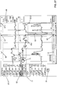
- FIG. 1 shows a ventilator 1 comprising a connector 3 and an output unit with a touch-sensitive screen 7, the information in able to output visual form to a user.
- This ventilator 1 carries out the artificial ventilation of the patient P.
- an optional additional input unit with a DV mouse 37 is shown.
- a data processing signal processing unit 5 of the ventilator 1 receives measured values from the sensors 2.1.1 to 2.2.2, 3, 4, 6, calculates patient-related signals using these measured values and causes selected signals to be displayed on the screen 7.
- the signal processing unit 5 controls a processor for the screen 7 and thereby causes the temporal progressions of various signals and other information to be displayed on the screen 7.
- the screen 7 and this processor belong to an output unit of the exemplary embodiment.
- the signal processing unit 5 receives measured values from sensors, for example from the in Figure 1 shown sensors 2.1.1 to 2.2.2, 3, 4, 6, and generates patient-related signals from measured values.
- the signal VT (amount of breathable air) is calculated by the signal processing unit 5 over several Integrated measurement values that describe the flow of breathable air at different times during a breath.
- the signal MV (amount of supplied breathable air) is calculated from the signal VT, for example by means of suitable averaging or from a signal section of the signal VT of 1 minute length.
- the screen 7 can be part of the ventilator 1 or it can also be spatially separated from the ventilator 1 and belong, for example, to a smartphone or other portable device.
- the signal processing unit 5 can also be spatially separated from the ventilator 1 and belong, for example, to the portable device.
- the screen 7 is preferably designed as a touch-sensitive screen (touchscreen), and the user can touch and move an element displayed on the screen 7, for example by moving a finger across the screen 7.
- the ventilator 1 or the spatially distant portable device comprises an additional input unit, for example a mouse 37 and / or a keyboard or a unit which recognizes voice inputs.
- the signal processing unit 5 is able to detect alarms. Each detectable alarm relates to at least one signal which the signal processing unit 5 has generated by evaluating measured values. An alarm is present and is automatically detected if this signal fulfills a predefined alarm criterion at at least one sampling point in time and / or for a period that is greater than a predetermined minimum period.
- a setpoint range in which the signal values should lie is predetermined.
- This target range can be constant over time or is calculated during use as a function of measured values and can therefore be variable over time.
- An alarm criterion for this signal is met if at least n1 Sampling times the value of a signal is below the lower limit of the target range.
- Another alarm criterion is met if the value of a signal is above the upper limit of the target range at at least n2 sampling times.
- the numbers n1 and n2 are specified and can be the same or differ from one another.
- An alarm criterion can also be met if the change or rate of change of a signal over time is above a predetermined change limit.
- the signal processing unit 5 continuously checks, e.g. with a predetermined sampling frequency, whether at least one patient-related signal fulfills a predetermined alarm criterion. It preferably checks for each signal whether an alarm criterion specified for this signal has been met. If this is the case, the signal processing unit 5 has detected an alarm of a specific alarm type. The alarm criterion detected as fulfilled defines the alarm type of the detected alarm. The signal processing unit 5 detects the type of alarm and the point in time or the earliest point in time at which this alarm occurred. Of course, an alarm of the same alarm type can occur several times in a row. Each alarm is identified by the type of alarm and the time it occurred.
- the signal processing unit 5 compares in particular the patient-related signals with predetermined limit values, for example with the limits of a target range, and generates a patient-related alarm if a signal value is above an upper limit value or below a lower limit value.
- An example of an alarm due to a deviating patient-related signal is "Pressure high" - the airway pressure P aw (pressure difference to ambient pressure) is above a predetermined upper limit value, for example 27 mbar.
- MV low the amount of breathing air supplied to the lungs is below a lower limit value, for example 3.65 liters / min.
- Another alarm is given if the breathing rate is above an upper limit ("RR high ").
- the signal processing unit 5 is also able to monitor system states of the ventilator 1 and to generate a technical alarm, for example the alarm "battery charge state low". This alarm is triggered when the charge level of the battery of the ventilator 1 is so low that this battery could not bridge a temporary failure of a stationary voltage supply network or the disconnection of the ventilator 1 from the voltage supply network for a sufficiently long time. Another device-related alarm is generated, for example, if a sensor cannot deliver a valid measured value.
- the signal processing unit 5 is capable of capturing and processing inputs from a user.
- the signal processing unit 5 controls the screen 7 as a function of captured user inputs and causes the screen 7 to display various representations in response to the user input, which is described below.
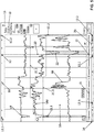
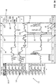
- the three time profiles of three signals VT, MV, RR, which are shown in the signal profile area 10, relate to a reference time window T1, which in this case extends from 12:00 to 14:00.
- the reference time axis 15 in the alarm overview display 14 relates to this reference time window T1.
- the three time signal curves VT, MV, RR shown also relate to the reference time axis 15 and show the respective curve of the signal in the reference time window T1.
- a reference point in time line 20 on the screen 7 is perpendicular to the reference time axis 15 and indicates the variable and changeable reference point in time t0 in which in FIG Figure 2 The situation shown is the current time at 2:00 p.m.
- This reference point in time line 20 also relates to the reference time axis 15. Initially, the reference point in time t0 is the current point in time, in this case 2:00 p.m. A user can specify an earlier point in time as the changed reference point in time t0, which is described below.
- Each alarm relates to a signal, in the example shown to the signal MV or to the signal VT or to the signal RR, and is detected when a predetermined alarm criterion is met.
- Each predefined alarm criterion defines an alarm type, for example the alarm types "Signal MV too low” ("MV low”) or "Signal RR too high” ("RR high").
- an overall alarm sequence 16 which is located below the reference time axis 15, a chronological sequence of alarms is shown.
- This overall alarm sequence 16 relates to a total time period T during the therapy of the patient P, the total time period T being greater than the reference time window T1 represented by the reference time axis 15.
- the reference time window T1 is therefore a section of the total time period T.
- the time scale the reference time axis 15 is finer than the time scale of the overall alarm sequence 16.
- the overall alarm sequence 16 does not use the reference time axis 15, but an overall time axis that is not shown in one embodiment and not by numerical time information is described in order to save space on the screen 7.
- This total time axis shows the same time span with less space than the reference time axis 15, and therefore the total time axis for the total time period T is preferably just as long as the reference time axis 15 for the reference time window T1, although the total -Time period T is longer than the reference time window T1.
- the overall time axis necessarily uses a coarser time scale than the reference time axis 15.
- the overall alarm sequence 16 is always displayed. It provides an overview of the entire period of therapy and enables a user to directly select a different reference time window T1. In another embodiment, the overall alarm sequence 16 is shown or hidden depending on a user input.
- An alarm reference section 26 of this overall alarm sequence 16 indicates when which alarm types occurred in the reference time window T1 and how the reference time window T1 is positioned in the time period T.
- the alarm overview display 14 thus shows, through the alarm reference section 26 and the overall alarm sequence 16, which section of the total time period T the reference time window T1 currently occupies, that is to say a positioning display. This section can be changed.
- the overall time axis is used for the alarm reference section 26 in the exemplary embodiment.
- the alarm reference section 26 is a section of the overall alarm sequence 16, which saves space on the screen 7. It is also possible for the alarm reference section 26 to be shown spatially separated from the overall alarm sequence 16. Each alarm that occurred in the reference time window T1 is thus represented twice in this different implementation, namely once in the overall alarm sequence 16 and once in the alarm reference section 26.
- the length of the reference time window T1 is displayed in a duration window 30, here 2h.
- An initial length of time is given.
- a user can change the length of the reference time window T1 and also change the reference time window T1 in this way.
- Each alarm that was detected in the reference time window T1 is represented in the overall alarm sequence 16 and in the alarm reference sequence 18 by the symbol for the corresponding alarm type.
- the times of the alarms shown in the alarm-reference sequence 18 relate to the reference time window T1, which is shown using the reference time axis 15.
- the reference time axis 15 is therefore also used for the alarm-reference sequence 18.
- the alarm-reference sequence 18 also relates to the reference time axis 15 and uses the same finer time scale as the signal curve representation 10.
- a separate symbol is specified for each type of alarm, and each alarm is displayed in the overall alarm sequence 16, the alarm reference sequence 18 and the alarm reference section 26 with the aid of the symbol for the alarm Art shown.
- each alarm goes off represented by means of a circle or other symbol, the color and / or shape of this symbol depending on the relevance of the alarm type.
- the "MV low” alarm type is assigned the "high” relevance, which is shown with a red circle 17.1, and the "medium” relevance to the alarm type, which is shown with a yellow circle 17.2, cf. Figure 11 .
- time axis display direction ZR shown.
- the reference time axis 15, the overall alarm sequence 16 and the alarm reference section 26 extend in this time axis display direction ZR.
- the time axis display direction ZR shows from older to newer times.
- the x-axis of the signal curves that are displayed in the signal curve area 10 is parallel to this time axis display direction ZR.
- the time axis display direction ZR points to the right; a different orientation is also possible.
- a user selects a displayed alarm 12.
- the user can do this in different ways.
- Figure 4 The user selects an alarm 12, which is shown in the alarm-reference sequence 18, for example by touching the representation for this alarm 12 with a finger.
- the circle 19 illustrates in Figure 4 and in the following figures the respective selection and interaction by a user. Further possibilities are given below as to how a user can select a displayed alarm 12.
- Figure 6 shows in a detailed representation of Figure 5 , as the alarm overview representation 14 of Figure 3 changed after alarm 12 was selected.
- the alarms 12.1, 12.2 and 12.3 of the alarm type "MV low” are highlighted (here: black) and the others are not highlighted ( here: white with black frame).
- This embodiment makes it possible to highlight all alarms of the alarm type "MV low” without using a special symbol for the alarm type "MV low", namely by only emphasizing the alarms "MV low”. It can be seen where in the alarm reference section 26 the selected alarm 12 is arranged.
- the alarm overview display 14 also shows where the selected alarm 12 is temporally arranged in the total time period T. Alarm 12.3 can also be seen, which lies outside the reference time window T1.
- Figure 7 and Figure 8 illustrate how the user specifies an earlier reference time window T1 and selects an alarm of the same type in the earlier reference time window T1.
- the total time period T remains unchanged.
- the predefined earlier reference time window T1 should include the point in time at which the alarm 12.3 of the same type was detected.
- the user touches the Alarm reference section 26 and pulls it to the left over the time of the alarm 12.3, cf. the circle 19 and the arrow pointing to the left in FIG Figure 7 .
- the user selects the alarm 12.3, for example by touching the representation in the overall alarm sequence 16 with a finger, cf. Figure 8 .
- the user has selected an alarm by selecting a symbol for the alarm type and the time arrangement in the overall alarm sequence 16 or in the alarm reference section 26.
- Another way to select an alarm is shown below.
- the starting point is again the initial situation, which is shown in Figure 2 will be shown.
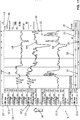
- an alarm description sequence 11 is additionally shown as a reaction to this, namely to the left of the signal curve area 10.
- this alarm description sequence 11 shows textual descriptions of a sequence of a maximum of N in immediate succession following alarms, the number N preferably depending on the vertical dimension of the screen 7 and on the preferably changeable font size.
- the alarm description sequence 11 shows these N alarm descriptions in an order from top to bottom, with the alarm description of the most recent alarm in the sequence shown at the top.
- Each alarm description occupies the same vertical space in the alarm description sequence 11 - provided the alarm descriptions are displayed in a horizontal writing direction SR.
- the alarm description sequence 11 is a chronologically ordered list of textual alarm descriptions, this list relating to a sequence of a maximum of N alarms and these alarms having been detected in the total period T.
- some alarms were detected in the reference time window T1, for example alarm 12 at time 13:33 and alarm 12.2 at time 13:59.
- the list extends in the list direction LR.
- This list direction LR is preferably perpendicular to the time axis display direction ZR.
- the list direction LR is vertical. The younger an alarm is, the higher up its alarm description is in this ordered list 11.
- the writing direction SR of an individual alarm description is perpendicular to the list direction LR and is therefore - in the case of a two-dimensional display - parallel to the time axis display.
- Direction ZR A perspective, i.e. spatial, representation is also possible.
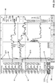
- the reference time window T1 is shortened in time.
- the time scale and thus the display scale remain unchanged, but there is less space available for the reference time window T1.
- the finer time scale remains unchanged.
- the shortened reference time window T1 extends from 12:20 p.m. to 2 p.m., that is to say is about 20 minutes shorter.
- the alarms that are displayed in the alarm description sequence 11 have been detected in the original reference time window T1, which lasts from 12:00 p.m. to 2:00 p.m. In one embodiment, it is possible that an alarm displayed in the alarm description sequence 11 is no longer in the shortened reference time window T1, which lasts from 12:20 p.m. to 2 p.m., for example alarm 12.1 at the time 12:03 p.m.
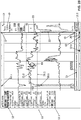
- the embodiment just described is useful if the textual descriptions are presented in a language that provides a horizontal writing direction, for example from left to right in English or German or from right to left in Hebrew or Arabic. If the textual descriptions are presented in a language with a vertical writing direction, for example traditional Chinese or Japanese, the presentation is preferably adapted accordingly.
- the time axis display direction ZR and the writing direction SR of a textual alarm description run vertically, and the list direction LR is horizontal.
- the language in which textual outputs are to be generated can preferably be configured, and this defines the writing direction and thus the time axis display direction ZR and the list direction LR.
- the alarm description sequence 11 extends in the list direction LR, with an alarm description of an alarm in the sequence being shown higher up the more recent the alarm is.
- Figure 12 the list direction LR of the alarm description sequence 11 and the writing direction SR of the textual alarm description are also shown.
- the writing direction SR is perpendicular to the list direction LR.
- Figure 13 shows another starting point for the selection of an alarm of the alarm type "MV low".
- curves of the three signals SpO2, HR and Resp are shown, but not the curve of the signal MV.
- the user can select the alarm 12 in the alarm-reference sequence 18 or proceed as described below.
- a space 24 below the alarm description sequence 11 has remained free because the alarm description sequence 11 is correspondingly short.
- the number of alarms in the total time period T is specified which are before the reference time window T1 and which are therefore not shown in the alarm description sequence 11 and are of the same alarm type as the selected alarm 12, in in this case two alarms (+2), cf. Figure 16 .
- the user can click on the representation of this number, for example with a finger.
- the reference time window T1 changes, in this case to the period from 11:50 a.m. to 1:35 p.m., which is visible in the reference time axis 15.
- the finer time scale remains unchanged.
- the reference time t0 is now 12:03.
- the alarm-reference sequence 18 is shown shifted accordingly. Furthermore, it is shown in two places 24 that an earlier and a later alarm, which was detected in the total time period T before or after the reference time window T1, and is of the same alarm type as the selected alarm 12 (+1 ), are not shown in the changed alarm description sequence 11, cf. Figure 17 .
- FIG 20 to Figure 22 illustrate how a correlation indicator is used. This correlation indicator makes it easier for a user to find a specific alarm and the time at which this alarm occurred in the alarm-reference sequence 18.
- the correlation indicator comprises a leading element 32 and a guided element 33.
- the leading element 32 has the shape of a right-pointing triangle and the guided element 33 has the shape of a downward or upward pointing triangle.
- the leading element 32 always points to the uppermost alarm description in the alarm description sequence 11. This alarm description relates to an alarm which can lie in or outside the reference time window T1 and which is currently selected or not selected can be.
- the guided element 33 points to the symbol for this uppermost alarm in the alarm-reference sequence 18.
- the guided element 33 follows the leading element 32.
- the leading element 32 points to the uppermost alarm description, that is the one for alarm 12.2 (alarm type "MV low", time 13:59). This is also the in Figure 11 situation shown.
- the guided element 33 points to the symbol in the alarm-reference sequence 18 for this alarm 12.2.
- the user changes the sequence of alarms, the alarm descriptions of which are displayed in the alarm description sequence 11. This is indicated by the circle 19 and by the arrow pointing upwards.
- the alarm 34 (alarm type "RR high", time 1:55 pm) is the top alarm in the alarm description sequence 11, cf. Figure 21 .
- the leading element 32 therefore points to the alarm description for the alarm 34.
- the guided element 33 points to the symbol for this alarm 34 in the alarm reference sequence 18.
- Figure 22 shows the effect of further user input.
- the leading element 32 points to the alarm description for the alarm 35 (alarm type "Apnea", time 1:17 pm).
- the guided element 33 points to the symbol for this alarm 35 in the alarm-reference sequence 18.
- leading element 32 always points to the uppermost alarm description in the alarm description sequence 11. It is possible for the user to move the leading element 32 to another alarm description in the alarm description sequence 11.
- the guided element 33 then points to the corresponding alarm in the alarm-reference sequence 18. It is also possible that the leading element 32 points to an alarm in the alarm-reference sequence 18 and can be moved by the user.
- the guided element 33 points to the alarm description for that alarm in the alarm description sequence 11.
- a user can display which alarms that occurred before the current reference time window T1 belong to the same alarm type "MV low" as the currently selected alarm 12.1. The user is given the opportunity to move the reference time window T1.
- Figure 23 illustrates that the user is dragging the currently selected alarm 12.1 up in the alarm description sequence 11. This frees a place 24 in the alarm description sequence 11, in this case at the bottom. In this place 24, the number of those alarms is displayed that were detected in the total period T before the reference time window T1, also belong to the alarm type "MV low" and are currently not displayed in the alarm description sequence 11 , in this case "+1". The position of place 24 at the bottom left shows that this additional alarm was detected before the alarms displayed in the alarm description sequence 11.
- Figure 25 and Figure 26 show another way of shifting the illustrated reference time window T1.
- the starting point is again the situation, which in Figure 14 will be shown.
- the user touches the representation of the signal curve MV in the signal curve area 10 and pulls it to the right, which causes the reference time window T1 to be shifted to the left, that is to say at earlier times.
- the finer time scale in turn, remains unchanged. This shift is shown in Figure 25 indicated by the circle 19 and the arrow.
- Figure 27 and Figure 28 show an alternative embodiment.
- this alternative embodiment only those alarms are displayed in the alarm description sequence 11 which lie in the shortened reference time window T1. The number of further alarms of the same alarm type is displayed in place 24.
- Figure 29 shows another procedure for how a user can change the alarm sequence, the alarm descriptions of which are displayed in the alarm description sequence 11. This enables the user to select an alarm type, in this case the alarm type "RR high".
- the starting point is the situation in Figure 11 will be shown.
- the user selects an alarm in the alarm description sequence 11, here the alarm of the alarm type "VT" at time 12:36, and pulls this selected alarm up in the alarm description sequence 11. This is done in Figure 29 indicated by the circle 19 and the arrow pointing upwards.
- FIG 30 shows the situation after moving.
- the alarm 34 of the alarm type "RR high" at the time 13:55 is shown as the uppermost alarm.
- the reference time t0 was the current time (here: 2:00 p.m.) or the time of an alarm. The user can also temporarily specify any other reference point in time t0. A previously made selection of an alarm is preferably retained. Farther The sequence of alarms whose alarm descriptions are represented in the alarm description sequence 11 is preferably retained.
- FIG. 31 The definition of a temporary reference point in time t0 is illustrated Figure 31 .
- the preferably vertical reference point in time line 20 functions as a cursor. The user touches this reference point in time line 20 and slides it to the right and holds it at a desired point in time, which is in Figure 31 indicated by the circle 19 and the arrow pointing to the right.
- the user has specified the time 13:44 by moving and holding, which is not necessarily the time of an alarm.
- the reference time window T1 as well as the selection of the alarm type "MV low" and the selection of the alarm 12 are retained.
- Figure 33 shows an example.
- the user has shifted the reference point in time line 20 further and selected the point in time 13:59 as the reference point in time t0, which is the point in time of alarm 12.2.
- the user preferably keeps line 20 for reference time t0 at the time of alarm 12.2. This holding is indicated by the circle 19 in Figure 33 indicated.
- this reference point in time t0 remains selected only as long as the user holds the reference point in time line 20 at the corresponding point.
- the user can of course move and hold the reference point in time line 20, and the display is adapted accordingly.
- the point in time of the last selected alarm becomes the reference point in time t0 again. This will restore the in Figure 31 The situation shown with the selected alarm 12 is established.
- the user can have explanations of an alarm displayed. Show this Figure 35 and Figure 36 . In the Figure 35 situation shown is the same as in Figure 14 will be shown. The user has selected alarm 12 and that alarm 12 is highlighted.
- the user selects the highlighting of the alarm 12 in the alarm description sequence 11, which is shown in FIG Figure 35 is illustrated by the circle 19.
- two text windows 27 and 28 are displayed next to the selected alarm 12.
- a cause or explanation for the alarm 12 is displayed in the text window 27 - here, that the value exceeds the specified lower limit 21.1 has fallen below.
- Possible remedies for eliminating the cause are displayed in the text window 28.
- the user can have the temporal progressions of corresponding or other signals or also variables that can be set on the ventilator 1 displayed. Illustrate this Figure 37 and Figure 38 .
- the starting point is again the situation of Figure 14 .
- the user selects a symbol ("+") in the signal value area 13, which is shown in FIG Figure 37 is represented by the circle 19.
- a selection menu 29 is displayed, which offers two tabs and the names of different signals for selection, cf. Figure 38 .
- the first tab “Measurement”, allows you to select a patient-related signal that should also be displayed.
- the second tab, “Settings” allows you to display the current value of a previously selected variable that can be set on the ventilator 1. In the exemplary embodiment, however, the user cannot change this value in the user interface shown, but only in a different way, preferably directly on the ventilator 1.
- Figure 42 shows the reactions to this input.
- a number of operating elements are displayed in a column 41 that is now displayed on the screen 7.1.
- the alarm reference section 26 is now displayed.
- an alarm description sequence 11 is displayed in the vertical direction, the most recent alarm 40 at the top.
- the alarm description sequence 11 is displayed in the space that is in the situation of Figure 40 was occupied by the waveform area 10.
- the most recent Alarm 40 occurred at 9:14:50 PM.
- the user has selected this alarm 40.1, which is indicated by the border.
- further alarms are shown, for example "bradycardia” at 9:05:15 pm, an event marking, namely "marked event” at 8:58:45 pm, and a special action that is carried out on patient P, for example transport ("Transport docked", which ended at 9:00 pm).
- the event marker was set manually by the user in order to record a special situation. The user can later analyze this particular situation. In one embodiment, the user can enter a textual comment on this particular situation (not shown).
- a leading element 32 and a guided element 33 of the correlation indicator are again displayed, see also Figure 20 to Figure 22 .
- a user can scroll the section of the alarm description sequence 11 shown on the screen 7.1 up and down ("scroll"). If an alarm not shown in the current alarm reference section 26 arrives at the position of the leading element 32, the reference time window T1 and the alarm reference section 26 are adapted so that this alarm is now in the reference time window T1 lies. In one embodiment, the finer time scale also remains unchanged here.
- the user has selected the description of the alarm 40.1 in the alarm description sequence 11.
- the reference point in time t0 jumps to the point in time of this alarm 40.1, namely to 21:03:45.
- the user has operated the operating element 42 in column 41.
- a so-called waveform snippet view is displayed in the signal curve area.
- a time axis 43 is shown below this signal curve area.
- the reference point in time t0 lies in the middle of this time axis 43.
- the user can change the current temporal resolution of the waveform snippet view by selecting the operating elements with “+” and “-” in the two magnifying glasses shown to the right of the time axis 43 actuated.
- the controls " ⁇ " and ">" to the right of the alarm reference section 26 the user can select earlier and later alarms of the same alarm type and thereby shift both the reference time t0 and the reference time window T1 .
- Figure 44 shows how the courses of different signals are represented as trend courses, the signals in one embodiment being mathematically smoothed beforehand.
- the representation of the trend progression depends on the selected time resolution, the sampling frequency and the number of image points (pixels) to be represented.
- the signal curves relate to the reference time window T1, which goes back half an hour.
- the reference time axis 15 for the reference time window T1 is displayed under the central signal curve area 10.
- the values of the signals shown at the reference time t0 equal to 21:03:45 o'clock are displayed in an area 13.
- the value for SpO2 at reference time t0 was too low (alarm).
- the signal curves are indicated by numerical values.
- the representation again relates to the reference time window T1, which comprises the last 30 minutes before the current point in time (“Now”).
- the reference time t0 is again equal to 21:03:45.
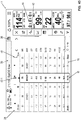
- Further signal values are displayed numerically in time steps of 5 minutes. This interval can be changed by the user touching the button labeled "5 min”.
- the set filter has an effect both on which alarms are shown in the alarm reference section 26 and on which alarms are described in the alarm description sequence 11. It is also shown how many alarms have currently occurred (28 pieces) and which alarm is currently displayed in field 39 (the most recent alarm 40 of the alarm type "SpO2 low").
- the configuration described so far relates to a medical device 1 which comprises its own signal processing unit 5 and its own output unit 7.
- the signal processing unit 5 has the effect that the information about the alarms is displayed on this output unit 7 as described above.
- a data network of several medical devices is described by way of example.
- This system can also include further ventilators and / or other medical devices.
- the two ventilators 1 and 1.2 and the central signal processing unit 51 are therefore connected to one another by a data network.
- the central signal processing unit 51 controls the central output unit 52.
- Both local signal processing units 5 and 5.2 receive measured values from the patient sensors of ventilators 1 and 1.2 as described above, generate signals, check whether predetermined alarm criteria are met, detect alarms and control the local output unit 7 and 7.2. These alarms relate to ventilator 1 or 1.2.
- the local signal processing units 5 and 5.2 write information about the detected alarms into the central data memory 50.
- the central signal processing unit 51 reads this central data memory 50, for example with a predetermined sampling frequency.
- the central signal processing unit 51 evaluates the information that it has read from the central data memory 50 and has the effect that alarms from both ventilators 1 and 1.2 are displayed on the output unit 52 as described above.
- a user can selectively display alarms from ventilator 1 or from ventilator 1.2. In another embodiment, alarms from both ventilators 1 and 1.2 are displayed simultaneously on the central output unit 52.
Landscapes
- Health & Medical Sciences (AREA)
- Life Sciences & Earth Sciences (AREA)
- Engineering & Computer Science (AREA)
- Physics & Mathematics (AREA)
- Biomedical Technology (AREA)
- General Health & Medical Sciences (AREA)
- Public Health (AREA)
- Heart & Thoracic Surgery (AREA)
- Animal Behavior & Ethology (AREA)
- Veterinary Medicine (AREA)
- Medical Informatics (AREA)
- Biophysics (AREA)
- Pathology (AREA)
- Molecular Biology (AREA)
- Surgery (AREA)
- Physiology (AREA)
- Pulmonology (AREA)
- Business, Economics & Management (AREA)
- General Physics & Mathematics (AREA)
- Anesthesiology (AREA)
- Emergency Management (AREA)
- Oral & Maxillofacial Surgery (AREA)
- Dentistry (AREA)
- Cardiology (AREA)
- Hematology (AREA)
- General Business, Economics & Management (AREA)
- Emergency Medicine (AREA)
- Psychiatry (AREA)
- Signal Processing (AREA)
- Computer Vision & Pattern Recognition (AREA)
- Artificial Intelligence (AREA)
- Electromagnetism (AREA)
- Optics & Photonics (AREA)
- Primary Health Care (AREA)
- Epidemiology (AREA)
- Measuring And Recording Apparatus For Diagnosis (AREA)
- Alarm Systems (AREA)
- Measurement Of The Respiration, Hearing Ability, Form, And Blood Characteristics Of Living Organisms (AREA)
Applications Claiming Priority (1)
| Application Number | Priority Date | Filing Date | Title |
|---|---|---|---|
| DE102019008406.3A DE102019008406B4 (de) | 2019-12-04 | 2019-12-04 | Anordnung und Verfahren zum Darstellen von medizinischen Alarmen |
Publications (1)
| Publication Number | Publication Date |
|---|---|
| EP3831278A1 true EP3831278A1 (de) | 2021-06-09 |
Family
ID=73497586
Family Applications (1)
| Application Number | Title | Priority Date | Filing Date |
|---|---|---|---|
| EP20208612.0A Pending EP3831278A1 (de) | 2019-12-04 | 2020-11-19 | Anordnung und verfahren zum darstellen von medizinischen alarmen |
Country Status (5)
| Country | Link |
|---|---|
| US (1) | US11170624B2 (ja) |
| EP (1) | EP3831278A1 (ja) |
| JP (1) | JP7146881B2 (ja) |
| CN (1) | CN112890793B (ja) |
| DE (1) | DE102019008406B4 (ja) |
Citations (11)
| Publication number | Priority date | Publication date | Assignee | Title |
|---|---|---|---|---|
| US20030200117A1 (en) | 2002-04-23 | 2003-10-23 | Manetta Amy M. | System and user interface supporting trend indicative display of patient medical parameters |
| US20050038332A1 (en) | 2001-12-27 | 2005-02-17 | Frank Saidara | System for monitoring physiological characteristics |
| US20080078390A1 (en) | 2006-09-29 | 2008-04-03 | Nellcor Puritan Bennett Incorporated | Providing predetermined groups of trending parameters for display in a breathing assistance system |
| US20110138311A1 (en) | 2009-12-04 | 2011-06-09 | Nellcor Puritan Bennett Llc | Display Of Respiratory Data On A Ventilator Graphical User Interface |
| US20130032149A1 (en) * | 2011-08-04 | 2013-02-07 | General Electric Company | Method and system for visualizing mechanical ventilation information |
| US20130246089A1 (en) | 2010-08-03 | 2013-09-19 | Koninklijke Philips Electronics N.V. | Method for display and navigation to clinical events |
| EP2777488A1 (en) * | 2013-03-14 | 2014-09-17 | Depuy Synthes Products, Inc. | Methods and systems for displaying medical parameters of a patient |
| WO2016188741A1 (en) * | 2015-05-26 | 2016-12-01 | Koninklijke Philips N.V. | Device, system and method for visualization of patient-related data |
| DE102016001139A1 (de) | 2016-02-03 | 2017-01-26 | Drägerwerk AG & Co. KGaA | Beatmungssystem mit einer Anzeigeeinrichtung |
| US20180277243A1 (en) | 2015-10-10 | 2018-09-27 | Shenzhen Mindray Bio-Medical Electronics Co., Ltd. | Medical monitoring system, method of displaying monitoring data, and monitoring data display device |
| US20180300919A1 (en) | 2017-02-24 | 2018-10-18 | Masimo Corporation | Augmented reality system for displaying patient data |
Family Cites Families (22)
| Publication number | Priority date | Publication date | Assignee | Title |
|---|---|---|---|---|
| US5860918A (en) * | 1996-11-22 | 1999-01-19 | Hewlett-Packard Company | Representation of a review of a patent's physiological parameters |
| US7308894B2 (en) * | 1998-06-03 | 2007-12-18 | Scott Laboratories, Inc. | Apparatuses and methods for providing a conscious patient relief from pain and anxiety associated with medical or surgical procedures according to appropriate clinical heuristics |
| DE102004050717B8 (de) | 2004-10-19 | 2006-02-23 | Dräger Medical AG & Co. KGaA | Anästhesievorrichtung |
| JP5584413B2 (ja) | 2005-06-22 | 2014-09-03 | コーニンクレッカ フィリップス エヌ ヴェ | 患者監視システム及び監視する方法 |
| DE102007038975A1 (de) | 2007-06-30 | 2009-01-02 | Dräger Medical AG & Co. KG | Verfahren und Vorrichtung zum Überwachen eines Patienten während der Narkose und zum Bestimmen eines gemeinsamen Effekts mehrerer Anästhetika |
| JP2009239507A (ja) * | 2008-03-26 | 2009-10-15 | Smk Corp | 監視システム |
| JP2011147493A (ja) * | 2010-01-19 | 2011-08-04 | Omron Healthcare Co Ltd | 生体情報監視装置、警報値設定方法および警報値設定プログラム |
| US9378111B2 (en) * | 2010-11-11 | 2016-06-28 | Sap Se | Method and system for easy correlation between monitored metrics and alerts |
| CA2835937A1 (en) * | 2011-05-15 | 2012-11-22 | Spacelabs Healthcare, Llc | User configurable central monitoring station |
| AU2013249502B2 (en) * | 2012-04-16 | 2017-12-14 | Airstrip Ip Holdings, Llc | Systems and methods for displaying patient data |
| EP2851824A1 (en) * | 2013-09-20 | 2015-03-25 | Sanofi-Aventis Deutschland GmbH | Data management unit for supporting health control |
| DE102014002172A1 (de) | 2014-02-19 | 2015-08-20 | Dräger Medical GmbH | Überwachungsmonitor zur elektronischen Überwachung von Sensorsignalen im Rahmen eines Sepsismonitorings, sowie ein entsprechendes Verfahren |
| CN103901305B (zh) * | 2014-03-31 | 2017-01-18 | 广东电网公司电力科学研究院 | 电力设备的在线预警方法 |
| US10387613B2 (en) | 2015-08-03 | 2019-08-20 | Drägerwerk AG & Co. KGaA | Displaying status of medical lines |
| US20170098358A1 (en) * | 2015-10-01 | 2017-04-06 | Cerner Innovation, Inc. | Generating informative alarm notifications to identify patient need and data quality |
| CN107784799B (zh) * | 2016-08-26 | 2019-07-19 | 北京协同创新智能电网技术有限公司 | 一种基于在线变化方向的多变量报警方法及系统 |
| DE102016015119A1 (de) | 2016-12-20 | 2018-06-21 | Drägerwerk AG & Co. KGaA | Vorrichtung, Verfahren und Computerprogramm zur Konfiguration eines medizinischen Gerätes, medizinisches Gerät, Verfahren und Computerprogramm für ein medizinisches Gerät |
| JP7176913B2 (ja) * | 2017-10-12 | 2022-11-22 | 日本光電工業株式会社 | 生体情報処理装置、生体情報処理方法、プログラム及び記憶媒体 |
| CA3025386A1 (en) * | 2017-11-27 | 2019-05-27 | Pelmorex Corp. | Systems and methods for location-based alert generation |
| CN108720826A (zh) * | 2018-03-20 | 2018-11-02 | 上海理工大学 | 基于激光散斑的运动伤害预警方法 |
| US11042735B2 (en) | 2018-09-25 | 2021-06-22 | Drägerwerk AG & Co. KGaA | System and method for verifying whether text will be properly rendered in a target area of a user interface and/or a graphics file |
| CN109191800A (zh) * | 2018-10-25 | 2019-01-11 | 蚁图信息技术(上海)有限公司 | 适用于糖尿病患者服药后低血糖监测报警方法及装置 |
-
2019
- 2019-12-04 DE DE102019008406.3A patent/DE102019008406B4/de active Active
-
2020
- 2020-11-19 EP EP20208612.0A patent/EP3831278A1/de active Pending
- 2020-12-02 US US17/109,984 patent/US11170624B2/en active Active
- 2020-12-03 JP JP2020201016A patent/JP7146881B2/ja active Active
- 2020-12-04 CN CN202011397833.8A patent/CN112890793B/zh active Active
Patent Citations (12)
| Publication number | Priority date | Publication date | Assignee | Title |
|---|---|---|---|---|
| US20050038332A1 (en) | 2001-12-27 | 2005-02-17 | Frank Saidara | System for monitoring physiological characteristics |
| US20030200117A1 (en) | 2002-04-23 | 2003-10-23 | Manetta Amy M. | System and user interface supporting trend indicative display of patient medical parameters |
| US20080078390A1 (en) | 2006-09-29 | 2008-04-03 | Nellcor Puritan Bennett Incorporated | Providing predetermined groups of trending parameters for display in a breathing assistance system |
| US20110138311A1 (en) | 2009-12-04 | 2011-06-09 | Nellcor Puritan Bennett Llc | Display Of Respiratory Data On A Ventilator Graphical User Interface |
| US20130246089A1 (en) | 2010-08-03 | 2013-09-19 | Koninklijke Philips Electronics N.V. | Method for display and navigation to clinical events |
| US20130032149A1 (en) * | 2011-08-04 | 2013-02-07 | General Electric Company | Method and system for visualizing mechanical ventilation information |
| EP2777488A1 (en) * | 2013-03-14 | 2014-09-17 | Depuy Synthes Products, Inc. | Methods and systems for displaying medical parameters of a patient |
| US20140275819A1 (en) | 2013-03-14 | 2014-09-18 | DePuy Synthes Products, LLC | Methods, systems, and devices for monitoring and displaying medical parameters for a patient |
| WO2016188741A1 (en) * | 2015-05-26 | 2016-12-01 | Koninklijke Philips N.V. | Device, system and method for visualization of patient-related data |
| US20180277243A1 (en) | 2015-10-10 | 2018-09-27 | Shenzhen Mindray Bio-Medical Electronics Co., Ltd. | Medical monitoring system, method of displaying monitoring data, and monitoring data display device |
| DE102016001139A1 (de) | 2016-02-03 | 2017-01-26 | Drägerwerk AG & Co. KGaA | Beatmungssystem mit einer Anzeigeeinrichtung |
| US20180300919A1 (en) | 2017-02-24 | 2018-10-18 | Masimo Corporation | Augmented reality system for displaying patient data |
Also Published As
| Publication number | Publication date |
|---|---|
| JP7146881B2 (ja) | 2022-10-04 |
| US20210174662A1 (en) | 2021-06-10 |
| CN112890793B (zh) | 2024-03-15 |
| JP2021087781A (ja) | 2021-06-10 |
| DE102019008406A1 (de) | 2021-06-10 |
| CN112890793A (zh) | 2021-06-04 |
| US11170624B2 (en) | 2021-11-09 |
| DE102019008406B4 (de) | 2024-02-01 |
Similar Documents
| Publication | Publication Date | Title |
|---|---|---|
| DE102012107078A1 (de) | Verfahren und System zur Visualisierung von Information über künstliche Beatmung | |
| US20150248534A1 (en) | System And Method Of Generating A User Interface Display Of Patient Parameter Data | |
| DE112007002265T5 (de) | System zum Verarbeiten, Herleiten und Anzeigen von Beziehungen zwischen medizinischen Patientenparametern | |
| DE60303029T2 (de) | Verfahren und gerät zur anzeige eines herzfrequenzsignals | |
| DE10225316A1 (de) | Verfahren zur Optimierung der Darstellung von mittels Bedienelemente frei platzier-und skalierbaren Objekten einer Benutzeroberfläche auf einem Bildschirm | |
| DE102012108430A1 (de) | System und Verfahren zum Anzeigen physiologischer Information | |
| DE102004006310A1 (de) | Medizinisches Patientenparameter-Benutzerschnittstellensystem | |
| EP0343405A1 (de) | Verfahren zur überwachung von Patientendaten und Schaltungsanordnung hierzu | |
| DE102011001662A1 (de) | System und Verfahren zum Durchführen von Elektrokardiographie mit Bewegungserfassung | |
| US20140032241A1 (en) | Method, apparatus and computer program product for monitoring clinical state of a subject | |
| DE102007028901B4 (de) | Verfahren und Vorrichtung zur automatischen Bestimmung von Perfusion mittels einer Magnetresonanzanlage | |
| DE102016107603B4 (de) | Benutzerinterface eines medizinischen Diagnosesystems sowie Computerprogramm dafür | |
| DE102014002172A1 (de) | Überwachungsmonitor zur elektronischen Überwachung von Sensorsignalen im Rahmen eines Sepsismonitorings, sowie ein entsprechendes Verfahren | |
| DE19821761A1 (de) | Verfahren und Vorrichtung zur komprimierten optischen Darstellung medizinischer Daten | |
| DE102020124834A1 (de) | Ausgabevorrichtung für ein Beatmungsgerät | |
| LU101515B1 (de) | Anordnung und Verfahren zum Darstellen von medizinischen Alarmen | |
| DE102019008406B4 (de) | Anordnung und Verfahren zum Darstellen von medizinischen Alarmen | |
| EP0984372B1 (de) | Verfahren und Vorrichtung zum manuellen Erfassen unterschiedlicher Ereignisse oder Zustände | |
| DE112012006041T5 (de) | Anzeigevorrichtung für blutdruckbezogene Informationen | |
| DE102015215044A1 (de) | Verfahren und System zur Verarbeitung multimodaler Eingabesignale | |
| DE112021003997T5 (de) | Vorrichtung zum anzeigen von blutdruckbezogenen informationen, verfahren zum anzeigen von blutdruckbezogenen informationen und programm | |
| DE102021110674A1 (de) | Bewegungsbewertungssystem, bewegungsbewertungsvorrichtung und bewegungsbewertungsverfahren | |
| EP3748620A1 (de) | Anzeigesystem und verfahren zum anzeigen einer ausgabe eines elektromedizinischen gerätes | |
| DE102007038915A1 (de) | Verfahren und Vorrichtung zum Überwachen eines Patienten | |
| EP3865163A1 (de) | Auswertesystem für ein beatmungsgerät und verfahren |
Legal Events
| Date | Code | Title | Description |
|---|---|---|---|
| PUAI | Public reference made under article 153(3) epc to a published international application that has entered the european phase |
Free format text: ORIGINAL CODE: 0009012 |
|
| STAA | Information on the status of an ep patent application or granted ep patent |
Free format text: STATUS: REQUEST FOR EXAMINATION WAS MADE |
|
| 17P | Request for examination filed |
Effective date: 20210430 |
|
| AK | Designated contracting states |
Kind code of ref document: A1 Designated state(s): AL AT BE BG CH CY CZ DE DK EE ES FI FR GB GR HR HU IE IS IT LI LT LU LV MC MK MT NL NO PL PT RO RS SE SI SK SM TR |
|
| STAA | Information on the status of an ep patent application or granted ep patent |
Free format text: STATUS: EXAMINATION IS IN PROGRESS |
|
| 17Q | First examination report despatched |
Effective date: 20230124 |