EP3825186B1 - Kabelbaum, form und formsystem - Google Patents
Kabelbaum, form und formsystem Download PDFInfo
- Publication number
- EP3825186B1 EP3825186B1 EP21150151.5A EP21150151A EP3825186B1 EP 3825186 B1 EP3825186 B1 EP 3825186B1 EP 21150151 A EP21150151 A EP 21150151A EP 3825186 B1 EP3825186 B1 EP 3825186B1
- Authority
- EP
- European Patent Office
- Prior art keywords
- wall
- section
- mould
- sheathing
- mold
- Prior art date
- Legal status (The legal status is an assumption and is not a legal conclusion. Google has not performed a legal analysis and makes no representation as to the accuracy of the status listed.)
- Active
Links
Images


Classifications
-
- B—PERFORMING OPERATIONS; TRANSPORTING
- B60—VEHICLES IN GENERAL
- B60R—VEHICLES, VEHICLE FITTINGS, OR VEHICLE PARTS, NOT OTHERWISE PROVIDED FOR
- B60R16/00—Electric or fluid circuits specially adapted for vehicles and not otherwise provided for; Arrangement of elements of electric or fluid circuits specially adapted for vehicles and not otherwise provided for
- B60R16/02—Electric or fluid circuits specially adapted for vehicles and not otherwise provided for; Arrangement of elements of electric or fluid circuits specially adapted for vehicles and not otherwise provided for electric constitutive elements
- B60R16/0207—Wire harnesses
- B60R16/0215—Protecting, fastening and routing means therefor
-
- B—PERFORMING OPERATIONS; TRANSPORTING
- B29—WORKING OF PLASTICS; WORKING OF SUBSTANCES IN A PLASTIC STATE IN GENERAL
- B29C—SHAPING OR JOINING OF PLASTICS; SHAPING OF MATERIAL IN A PLASTIC STATE, NOT OTHERWISE PROVIDED FOR; AFTER-TREATMENT OF THE SHAPED PRODUCTS, e.g. REPAIRING
- B29C45/00—Injection moulding, i.e. forcing the required volume of moulding material through a nozzle into a closed mould; Apparatus therefor
- B29C45/14—Injection moulding, i.e. forcing the required volume of moulding material through a nozzle into a closed mould; Apparatus therefor incorporating preformed parts or layers, e.g. injection moulding around inserts or for coating articles
- B29C45/14065—Positioning or centering articles in the mould
-
- B—PERFORMING OPERATIONS; TRANSPORTING
- B29—WORKING OF PLASTICS; WORKING OF SUBSTANCES IN A PLASTIC STATE IN GENERAL
- B29C—SHAPING OR JOINING OF PLASTICS; SHAPING OF MATERIAL IN A PLASTIC STATE, NOT OTHERWISE PROVIDED FOR; AFTER-TREATMENT OF THE SHAPED PRODUCTS, e.g. REPAIRING
- B29C45/00—Injection moulding, i.e. forcing the required volume of moulding material through a nozzle into a closed mould; Apparatus therefor
- B29C45/14—Injection moulding, i.e. forcing the required volume of moulding material through a nozzle into a closed mould; Apparatus therefor incorporating preformed parts or layers, e.g. injection moulding around inserts or for coating articles
- B29C45/14549—Coating rod-like, wire-like or belt-like articles
-
- B—PERFORMING OPERATIONS; TRANSPORTING
- B60—VEHICLES IN GENERAL
- B60R—VEHICLES, VEHICLE FITTINGS, OR VEHICLE PARTS, NOT OTHERWISE PROVIDED FOR
- B60R16/00—Electric or fluid circuits specially adapted for vehicles and not otherwise provided for; Arrangement of elements of electric or fluid circuits specially adapted for vehicles and not otherwise provided for
- B60R16/02—Electric or fluid circuits specially adapted for vehicles and not otherwise provided for; Arrangement of elements of electric or fluid circuits specially adapted for vehicles and not otherwise provided for electric constitutive elements
- B60R16/0207—Wire harnesses
-
- H—ELECTRICITY
- H01—ELECTRIC ELEMENTS
- H01B—CABLES; CONDUCTORS; INSULATORS; SELECTION OF MATERIALS FOR THEIR CONDUCTIVE, INSULATING OR DIELECTRIC PROPERTIES
- H01B13/00—Apparatus or processes specially adapted for manufacturing conductors or cables
- H01B13/012—Apparatus or processes specially adapted for manufacturing conductors or cables for manufacturing wire harnesses
- H01B13/01209—Details
-
- H—ELECTRICITY
- H01—ELECTRIC ELEMENTS
- H01B—CABLES; CONDUCTORS; INSULATORS; SELECTION OF MATERIALS FOR THEIR CONDUCTIVE, INSULATING OR DIELECTRIC PROPERTIES
- H01B7/00—Insulated conductors or cables characterised by their form
- H01B7/0045—Cable-harnesses
-
- H—ELECTRICITY
- H01—ELECTRIC ELEMENTS
- H01B—CABLES; CONDUCTORS; INSULATORS; SELECTION OF MATERIALS FOR THEIR CONDUCTIVE, INSULATING OR DIELECTRIC PROPERTIES
- H01B7/00—Insulated conductors or cables characterised by their form
- H01B7/36—Insulated conductors or cables characterised by their form with distinguishing or length marks
- H01B7/365—Insulated conductors or cables characterised by their form with distinguishing or length marks being indicia imposed on the insulation or conductor
-
- H—ELECTRICITY
- H02—GENERATION; CONVERSION OR DISTRIBUTION OF ELECTRIC POWER
- H02G—INSTALLATION OF ELECTRIC CABLES OR LINES, OR OF COMBINED OPTICAL AND ELECTRIC CABLES OR LINES
- H02G3/00—Installations of electric cables or lines or protective tubing therefor in or on buildings, equivalent structures or vehicles
- H02G3/30—Installations of cables or lines on walls, floors or ceilings
- H02G3/32—Installations of cables or lines on walls, floors or ceilings using mounting clamps
-
- B—PERFORMING OPERATIONS; TRANSPORTING
- B29—WORKING OF PLASTICS; WORKING OF SUBSTANCES IN A PLASTIC STATE IN GENERAL
- B29K—INDEXING SCHEME ASSOCIATED WITH SUBCLASSES B29B, B29C OR B29D, RELATING TO MOULDING MATERIALS OR TO MATERIALS FOR MOULDS, REINFORCEMENTS, FILLERS OR PREFORMED PARTS, e.g. INSERTS
- B29K2827/00—Use of polyvinylhalogenides or derivatives thereof as mould material
- B29K2827/12—Use of polyvinylhalogenides or derivatives thereof as mould material containing fluorine
- B29K2827/18—PTFE, i.e. polytetrafluoroethylene, e.g. ePTFE, i.e. expanded polytetrafluoroethylene
-
- B—PERFORMING OPERATIONS; TRANSPORTING
- B29—WORKING OF PLASTICS; WORKING OF SUBSTANCES IN A PLASTIC STATE IN GENERAL
- B29K—INDEXING SCHEME ASSOCIATED WITH SUBCLASSES B29B, B29C OR B29D, RELATING TO MOULDING MATERIALS OR TO MATERIALS FOR MOULDS, REINFORCEMENTS, FILLERS OR PREFORMED PARTS, e.g. INSERTS
- B29K2859/00—Use of polyacetals, e.g. POM, i.e. polyoxymethylene, or derivatives thereof as mould material
-
- B—PERFORMING OPERATIONS; TRANSPORTING
- B29—WORKING OF PLASTICS; WORKING OF SUBSTANCES IN A PLASTIC STATE IN GENERAL
- B29L—INDEXING SCHEME ASSOCIATED WITH SUBCLASS B29C, RELATING TO PARTICULAR ARTICLES
- B29L2031/00—Other particular articles
- B29L2031/34—Electrical apparatus, e.g. sparking plugs or parts thereof
- B29L2031/3462—Cables
Definitions
- the invention relates to a wiring harness according to claim 1, a mold for producing a wiring harness according to claim 2 and a molding system according to claim 8.
- Wiring harnesses with individual cables for connecting different components in a motor vehicle are known.
- the cables are pulled along a mounting board and wrapped with a wrapping tape.
- the manufacturing of the wiring harness is essentially manual, making it particularly cost-intensive.
- an improved wiring harness for a motor vehicle can be provided in that the wiring harness has a cable bundle with at least two cables and a sheath.
- the cable bundle is at least partially embedded in the sheath.
- the sheath has a transition section.
- the transition section is arranged between the first sheath section and the second sheath section.
- the first sheath section has a first side surface and the second sheath section has a second side surface.
- the transition section has a transition surface which has an inclination relative to the first side surface and the second side surface.
- the inclination has an angle, wherein the angle has a value which is less than 45°, in particular less than 30°, in particular less than 20°, in particular less than 15°, in particular less than 10°.
- the sheathing ensures that the cable harness can be bent particularly easily and routed around tight radii.
- the sheathing also protects the individual cables in the cable bundle.
- the sheathing has a signaling element on its outside, wherein the signaling element is guided parallel to the cable bundle to signal a position of the cable bundle.
- the signaling element preferably extends substantially over the entire longitudinal extent of the sheathing, wherein the signaling element is designed, at least in sections, to correspond to a geometric configuration of a holding device of a shape.
- the signaling element has a first bulge, wherein the first bulge is bead-like, and/or wherein the signaling element has a recess on the outside of the sheath. This allows the cable bundle to be located particularly quickly in the sheath during repair of the cable harness.
- the first bulge extends substantially over an entire longitudinal extent of the casing.
- the cable harness has a first fastening element.
- the first fastening element is embedded at least partially in the sheathing.
- the first fastening element is designed to hold at least one of the cables of the cable bundle in a predefined position. In this way, heating of the cable harness can be defined, so that even local overheating of the cable harness is reliably avoided. Irreversible damage to the cable harness can thus be easily avoided.
- the wiring harness comprises a second fastening element.
- the second fastening element has a first portion embedded in the sheath.
- the second fastening element further comprises a second portion which is designed to engage with a vehicle component of the motor vehicle in order to fasten the wiring harness to the vehicle component.
- the sheathing comprises a first layer, a second layer, and preferably a third layer, wherein the cable bundle is embedded in the first layer, wherein the first layer comprises a first material and the second layer comprises a second material, wherein the second material preferably has a different, preferably greater, elasticity than the first material, wherein the second layer is preferably rectangular or has a ribbed structure, wherein the second layer preferably has a surface provided with a predefined surface structure on a side facing the first layer, wherein the second layer preferably has a flat surface on a side facing away from the first layer, wherein the third layer preferably is arranged on a side of the second layer facing away from the first layer, wherein the third layer comprises at least one material, wherein the third material has an adhesive and/or a third elasticity that is different, preferably lower, than the first and/or second elasticity.
- the second layer can thus serve as protection for the cable bundle, thus avoiding possible damage to the cable bundle, for example, from sharp edges of a
- the first layer is slimmer in the direction transverse to the cable bundle than the second layer, wherein the first layer is designed to engage an indentation of a vehicle component, wherein preferably the first layer has a trapezoidal cross-section and the second layer has a substantially rectangular cross-section.
- the sheath has a second bulge
- the cable harness can be passed through a leadthrough in a vehicle component
- the second bulge extends inclined to a longitudinal extent of the cable bundle
- the second bulge is designed to form, at least in sections, a preferably fluid-tight separation between two spaces of the vehicle component
- the second bulge has a bulge contour
- the second bulge is designed to press the bulge contour against a leadthrough contour of the leadthrough in order to provide a substantially fluid-tight separation between the spaces.
- the sheathing has a second bulge, wherein the second bulge extends inclined to a longitudinal extent of the cable bundle, wherein the second bulge is designed to have at least in sections a
- a fluid-tight separation is formed between two spaces of the vehicle component, wherein the second bulge has a bulge contour, wherein the second bulge is configured to press the bulge contour against an indentation contour of an indentation of a vehicle component in order to provide a frictional connection between the indentation and the second recess and to frictionally fasten the cable harness in the indentation.
- the sheathing comprises a first sheathing section and a second sheathing section.
- the first sheathing section has a first transverse extension relative to a first longitudinal extension direction of the first sheathing section.
- the second sheathing section has a second transverse extension relative to a second longitudinal extension of the second sheathing section.
- the first transverse extension is greater than the second transverse extension.
- an improved mold for producing a cable harness can be provided in that the mold has a wall and an opening.
- the wall delimits a molding space at least laterally.
- the molding space borders the opening on the top side.
- the wall has a first wall surface section, a second wall surface section, and a wall surface transition section, wherein the first wall surface section is preferably arranged lower than the second wall surface section, wherein the wall surface transition section is arranged between the first wall surface section and the second wall surface section, wherein the wall surface transition section is arranged inclined with respect to the first wall surface section and the second wall surface section, wherein the inclination preferably has an angle, wherein the angle has a value that is less than 45°, in particular less than 30°, in particular less than 20°, in particular less than 15°, in particular less than 10°. This prevents cracking in the cable harness at the transition between the first wall sheathing section and the second wall sheathing section.
- the upwardly open shape allows for the cables to be laid particularly easily during the harness production process, without having to wrap them around pins. This allows for particularly fast production. Furthermore, the cables can also be laid automatically using a robot, further reducing production costs through automation.
- the mold has a holding device.
- the holding device is arranged on the wall and covers the opening at least in sections.
- the holding device is plate-like and/or brush-like, the holding device comprising a material that is reversibly elastically deformable and the holding device is bendable reversibly by at least 70°, preferably by 90°, preferably into the mold cavity. This prevents the cables inserted into the mold cavity from accidentally slipping out. Floating of the cables in the mold cavity during foaming of the sheath is also prevented.
- the wall has a wall base, wherein the holding device is arranged at least in sections parallel to the wall base.
- the wall has a first wall section and a second wall section.
- the first wall section is arranged opposite the second wall section, wherein the holding device comprises a first holding element and a second holding element, wherein the first holding element is arranged on the first wall section and the second holding element is arranged on the second wall section, wherein the first holding element and the second holding element each terminate with a free end above the opening and close the mold space at least in sections, wherein preferably the first wall section and/or the second wall section is profiled in a wave-like manner at least in sections.
- the free ends of the holding elements are arranged at a distance from one another, and/or the holding devices are arranged overlapping over the opening.
- the first wall section has a first wall region and a second wall region, wherein the first wall region is arranged substantially parallel to the second wall section, wherein the second wall area in a direction away from the second wall section offset from the first wall region, so that the mold space has a widening, wherein the second wall region is formed corresponding to the first bulge contour and/or the second bulge contour.
- a recess is provided in the wall, wherein the recess is designed as a through-opening and is arranged in a wall base of the mold, wherein the wall base delimits the mold space on the underside, wherein the recess is designed to receive at least portions of the first and/or second fastening element of the cable harness, and/or wherein an ejector for removing the cable harness from the mold is designed to pass through the recess, wherein the recess is preferably designed to correspond to the ejector.
- a recess is provided in the wall, wherein the recess is designed to receive at least in sections the first and/or the second fastening element of the cable harness.
- first wall surface section and the second wall surface section are arranged in two planes arranged parallel to one another.
- the holding device is interrupted in sections and/or designed to follow the wall continuously.
- the holding device comprises silicone as its material.
- the wall comprises at least one of the following materials: polytetrafluoride, polyoxymethylene.
- These materials exhibit a particularly low surface tension compared to the sheathing material, ensuring reliable demolding of the cable harness after the sheathing has cured.
- the use of these materials for the wall also ensures that a large number of cable harnesses can be produced with the mold without the need for additional cleaning or reprocessing steps to create the original mold.
- the wall has a wall surface facing the mold cavity, wherein the wall surface is laser-polished at least in sections. Laser polishing softens any grooves present in the wall surface, which may arise in particular from milling the mold cavity into the mold, thus reliably ensuring demolding and removal of the cable harness from the mold.
- the wall is at least partially corrugated and/or ribbed and/or flatly profiled. This allows the wiring harness to be easily and optimally adapted to the geometric boundary conditions in the vehicle.
- a sealing element is arranged at one longitudinal end of the wall in order to at least partially prevent the casing from escaping from the molding space.
- the mold has a first mold part and a second mold part.
- the first mold part has a first engagement element at one longitudinal end.
- the second mold part has a first receptacle formed corresponding to the first engagement element at a longitudinal end of the second mold part facing the longitudinal end of the first mold part.
- the first engagement element engages in the first receptacle and connects the first mold part to the second mold part in a form-fitting manner, wherein the engagement element and the receptacle are formed in relation to one another in such a way that withdrawal in the longitudinal direction is blocked by the engagement of the engagement element in the receptacle, wherein preferably the engagement element and the first mold part are formed in one piece and from the same material. In this way, the mold can be expanded or adapted particularly easily.
- the mold is designed to be attached to a mounting board of a molding system.
- an improved molding system comprises a mold and a mounting board, the mold being designed as described above, the mold being mounted on a surface facing a mounting board.
- Side has a further engagement element and the mounting board has at least one grid field with a plurality of further receptacles on a side facing the mold, or wherein the mold has a further receptacle on a side facing the mounting board and the mounting board has a grid field with a plurality of further engagement elements on a side facing the mold, wherein the further engagement element and the further receptacle are arranged corresponding to one another, wherein the further engagement element engages in one of the further receptacles and connects the mounting board to the mold in a form-fitting, reversibly detachable manner, wherein the other further receptacles of the grid field remain free, or wherein one of the further engagement elements engages in the further receptacle and connects the mounting board to the mold in a form-
- Figures 1A to 4B , 6 to 22 , 24 to 35 serve to clarify general understanding.
- Figure 5 shows a wiring harness 1010 according to the invention and Figure 23 a mold according to the invention 15.
- FIG 1A shows a section of a cross-section through a vehicle component 1000 of a motor vehicle according to a first embodiment.
- the vehicle component 1000 has a structure 1005 and a wiring harness 1010.
- the structure 1005 can be, for example, a body, a deep-drawn part, a headliner, a door panel, an intermediate panel, a soundproofing bulkhead, or a cockpit.
- the structure 1005 can be made of sheet metal or plastic, for example. However, the structure 1005 can also be a plastic structure, a carpet, or the like.
- the structure 1005 has a contact surface 1015. The contact surface 1015 faces the wiring harness 1010.
- the cable harness 1010 comprises a cable bundle 1020 with several cables 1025.
- the cables 1025 are used to transmit electrical signals or an electrical current between two points.
- the cables 1025 are arranged in approximately the same direction relative to one another.
- the cables 1025 of the cable bundle 1020 are embedded in a sheath 1030 of the cable harness 1010.
- the sheath 1030 has a side surface 1035 with a sheath contour on the outside.
- the sheathing 1030 preferably comprises at least one of the following materials: polyurethane, silicone, foam, closed-cell foam, open-cell foam, silicone foam, polyurethane foam.
- the cable harness 1010 rests with the side surface 1035 against the contact surface 1015.
- An adhesive layer can additionally be provided between the contact surface 1015 and the side surface 1035 to firmly bond the cable harness 1010 to the structure 1005.
- the sheath 1030 comprises a signaling element 1038.
- the signaling element 1038 comprises a first bulge 1036, advantageously on an upper side 1037 of the cable harness 1010.
- the first bulge 1036 protrudes beyond the upper side 1037.
- the first bulge 1036 is preferably bead-like and preferably extends at least partially parallel to the cable bundle 1020.
- the signaling element 1038 can be arranged centrally to a maximum first transverse extent b 1 . This allows the course of the cables 1025 of the cable bundle 1020 to be signaled in a simple manner.
- the signaling element 1038 can be used to signal a predefined side for inserting the cable harness 1010 into the structure 1005, so that the cable harness 1010 can be installed particularly quickly during assembly of the motor vehicle. Additionally or alternatively, it is also conceivable that the signaling element 1038 comprises a recess 1040 in the upper side 1037 (dashed in Figure 1A shown). The recess 1040 may, for example, be used to signal a particular type of wiring harness 1010.
- Figure 1B a detail of a top view of the Figure 1A vehicle component shown 1000.
- the signaling element 1038 extends essentially over the entire longitudinal extent of the cable harness 1010. This makes it particularly easy to determine the insertion position of the cable bundle 1020 in the sheath 1030. This is particularly advantageous when the sheath 1030 is particularly thick and the cable bundle 1025 is neither palpable nor visually recognizable in the sheath.
- FIG 2 shows a sectional view through a vehicle component 1000 according to a second embodiment.
- the vehicle component 1000 is substantially identical to the vehicle component 1000 shown in Figure 1A.
- the structure 1005 has a first space 1100 and a second space 1105.
- a partition wall 1110 is provided between the first space 1100 and the second space 1105.
- the partition wall 1110 has an opening 1115.
- the cable harness 1010 is routed through the opening 1115.
- the wiring harness 1010 is essentially identical to the one in Figure 1A and Figure 1B explained cable harness 1010.
- the sheathing 1030 of the cable harness 1010 has a second bulge 1120.
- the second bulge 1120 extends transversely to a longitudinal extent of the cable bundle 1020.
- the sheathing 1030 advantageously has a soft-elastic material at least in the region of the second bulge 1120.
- the second bulge 1120 has a bulge contour 1121.
- the second bulge 1120 is arranged in the opening 1115 and fills the opening 1115.
- the second bulge 1120 is pressed/compressed into the opening 1115.
- the second bulge 1120 presses the bulge contour 1121 circumferentially against an opening contour 1122 of the opening 1115 and fluidically seals the first space 1100 from the second space. Furthermore, sound transmission between the first space 1100 and the second space 1105 through the second bulge 1120 is thereby prevented. It is particularly advantageous if the second bulge 1120 is arranged circumferentially around the cable bundle 1020. In this case, the second bulge 1120 can be particularly advantageously triangular in cross-section. This eliminates the need for a grommet in the opening 1115.
- Figure 3A shows a section of a cross section through a vehicle component 1000 of the motor vehicle according to a third embodiment.
- the vehicle component is similar to that in Figures 1 and 2 shown vehicle component 1000.
- the cable harness 1010 has a first layer 1200 and a second layer 1205.
- the second layer 1205 is on the underside of the first layer 1200 and between the first Layer 1200 and the structure 1005.
- the cable bundle 1020 is embedded in the first layer 1200.
- the first bulge 1036 borders the first layer 1200.
- the first layer 1200 preferably has a first material and the second layer 1205 preferably has a second material.
- the first layer 1200 and the second layer 1205 can also have an identical material.
- the second material can have a different elasticity than the first material. It is advantageous if the elasticity of the second material is greater than the elasticity of the first material, as rattling of the cable bundle 1020 on the structure 1005 can be avoided due to the particularly elastic properties of the second layer 1205.
- the second layer 1205 is rectangular in cross-section.
- Other configurations of the second layer 1205 are also conceivable.
- the second layer 1205 can also be semicircular, elliptical, U-shaped, C-shaped, cylindrical or otherwise.
- the second layer 1205, instead of the Figure 3 The planar configuration shown has a ribbed structure in the longitudinal direction of the cable harness 1010. This allows the cable harness 1010 to be guided particularly well around a radius, while at the same time ensuring a high level of protection for the cable bundle 1020 by the second layer 1205.
- Figure 3B shows a section of a cross-section of a further training of the Figure 3A shown vehicle component 1000.
- the wiring harness 1010 is essentially identical to that shown in Figure 3 shown cable harness 1010.
- the second layer 1200 has a defined surface structure 1215 on a surface 1220 facing the first layer 1200.
- the surface structure 1215 is, for example, wave-shaped. This increases the size of the surface 1220 of the second layer 1205 and prevents the first layer 1205 from adhering to the surface 1220 shown in Figure 3A shown embodiment at the second layer 1200.
- Figure 3C shows a section of a cross-section of a further training of the Figure 3A shown vehicle component 1000.
- the first layer 1200 is slimmer in the transverse direction to the cable bundle 1020 than the second layer 1205.
- the sheathing 1030 has a third layer 1210.
- the third layer 1210 is arranged on a side of the second layer 1205 facing away from the first layer 1200 and is connected to the latter.
- the third layer 1210 has a third material with a third elasticity.
- the third elasticity is preferably lower than the first elasticity and/or the second elasticity.
- the third layer 1210 is designed as a baffle plate or as an adhesive layer. When designed as a baffle plate, it is advantageous that the third layer 1210 can prevent damage to the cable bundle 1020 and, at the same time, vibrations can be dampened particularly well by the second layer 1205.
- the layers 1200, 1205, 1210 are arranged, for example, in a rectangular shape with identical width in a layer stack.
- the layers 1200, 1205, 1210 may also have different widths or configurations.
- Figure 3E shows a longitudinal section through a further training of the Figure 3A shown vehicle component 1000.
- a rib structure 1225 is provided in the second layer 1200.
- the rib structure 1225 has ribs 1230 and rib recesses 1235 arranged between the ribs 1230 in the longitudinal direction, which delimit the ribs 1230 in the longitudinal direction.
- the rib recesses 1235 each have a recess base 1240, which is arranged at a distance from the cables 1025 of the cable bundle 1020.
- FIG 4A shows a section of a cross section through a vehicle component 1000 of the motor vehicle according to a fourth embodiment.
- the vehicle component 1000 is essentially identical to the one shown in Figures 1A to 3E
- the structure 1005 has a groove-like indentation 1300 with an indentation contour 1301.
- the indentation 1300 is, for example, rectangular in shape.
- the indentation 1300 can be introduced into the structure 1005, for example, during a pressing process.
- the wiring harness 1010 is essentially identical to the one shown in the Figure 3A shown embodiment.
- the cable harness 1010 is arranged in the indentation 1300.
- the sheath 1030 has the second bulge 1120.
- the second bulge 1120 is preferably circumferential, encompassing the cable bundle 1020 on preferably three sides and preferably formed in a layered manner.
- the second bulge 1120 has a bulge contour 1121.
- the material of the second bulge 1120 is preferably elastic and integral and of the same material as the material of the casing 1030. In the unassembled state, the bulge contour 1121 of the second bulge 1120 is preferably larger than the indentation contour of the indentation 1300.
- the second protrusion 1120 and its material are compressed, so that the second protrusion 1120 presses its protrusion contour 1121 against the indentation contour of the indentation 1300, so that the wiring harness 1010 is frictionally connected to the indentation 1300 of the vehicle component 1000 via the second protrusion 1120.
- This allows the wiring harness 1010 to be accommodated in the structure 1005 of the vehicle component 1000 in a particularly space-saving manner.
- the structure 1005 has a surface 1310 adjacent to the indentation 1300, wherein the upper side 1037 of the cable harness 1010 is formed substantially seamlessly/steplessly relative to the surface 1310.
- the upper side 1037 and the surface of the structure 1005 lie in a common plane.
- the second bulge 1120 can be omitted from the cable harness 1010, wherein in this embodiment the cable harness 1010 substantially completely fills the indentation 1300.
- the second bulge 1120 can also be provided only in sections in the longitudinal direction; in the remaining regions (without the second bulge 1120), for example, the sheathing 1030 is arranged at a distance from the indentation contour 1305.
- Figure 4B shows a cross-section of a further training of the Figure 4A vehicle component shown 1000.
- the Figure 4B The design shown is essentially a combination of the Figure 3C shown configuration of the wiring harness 1010 with the Figure 4A shown embodiment of the vehicle component 1000.
- the vehicle component 1000 has, in addition to the structure 1005, a holding structure 1006, which is arranged on the upper side at a distance from the indentation 1300. Only the first layer 1200 engages in the indentation 1300, while the second layer 1205 is arranged outside the indentation 1300 between the holding structure 1006 and the structure 1005.
- the holding structure 1006 presses with a holding force F H against the second layer 1205 and thus secures the cable harness 1010 to the structure 1005.
- the holding structure 1006 can be Structure 1005.
- the support structure 1006 may also be another vehicle assembly to the structure.
- Figure 5 shows a longitudinal section through a cable harness 1010.
- the sheathing 1030 of the cable harness 1010 has a first sheathing section 1400, a second sheathing section 1405, and a transition section 1410.
- the transition section 1410 is arranged in the longitudinal direction of the cable harness 1010 between the first sheathing section 1400 and the second sheathing section 1405.
- the first sheathing section 1400 has a first side surface 1415
- the second sheathing section 1405 has a second side surface 1420.
- the side surfaces 1415, 1420 are preferably arranged parallel in two planes offset from one another.
- the side surfaces 1415, 1420 are, for example, flat. Another configuration of the side surfaces 1415, 1420 is also conceivable.
- the transition section 1410 has a transition surface 1425.
- the side surfaces 1415, 1420 and the transition surface 1425 can be arranged on the underside of the cable harness 1010, on the side of the cable harness 1010, or on the top of the cable harness 1010.
- the transition surface 1425 is arranged inclined with respect to the first side surface 1415 and the second side surface 1420.
- the inclination has an angle ⁇ 1 , wherein the angle ⁇ 1 has a value that is less than 45°, in particular less than 30°, in particular less than 20°, in particular less than 15°, in particular less than 10°. This prevents crack formation in the sheath 1030 at the transition between the first sheath section 1400 and the second sheath section 1405.
- the transition surface 1425 instead of the Figure 5
- the planar configuration shown is curved. In particular, a convex or concave curvature is conceivable.
- the first sheathing section 1400 has the first transverse extent b 1 relative to a first longitudinal extension direction of the first sheathing section 1400, and the second sheathing section 1405 has a second transverse extent b 2 relative to a second longitudinal extension direction of the second sheathing section 1405.
- the first transverse extent b 1 is greater than the second transverse extent b 2 .
- FIG. 5 An example is Figure 5 the first longitudinal direction is identical to the second longitudinal direction.
- the first longitudinal direction can also be different to the second longitudinal direction and, for example, the transition section 1410 may be curved.
- This configuration of the cable harness 1010 has the advantage that the width of the cable harness 1010 can be flexibly adapted to the installation space available on the structure 1005.
- Figure 6 shows a perspective view of a wiring harness 1010 in another embodiment.
- the wiring harness 1010 is similar to the one in the Figures 1 to 5 shown cable harness 1010. Deviating from this, the side surface 1035 is formed with an exemplary wave-like profile 1500.
- the profile 1500 has a first profile section 1505 and a second profile section 1510.
- the first profile section 1505 is, for example, wider in the longitudinal direction than the second profile section 1510.
- the first profile section 1505 is concave and the second profile section is convex.
- the first and second profile sections 1505, 1510 alternate in the longitudinal direction.
- Figure 7 shows a perspective view of a wiring harness 1010 in another embodiment;
- the wiring harness 1010 is essentially identical to the one in Figure 6 shown cable harness 1010. Deviating from this, the first profile section 1505 and the second profile section 1510 are of identical width.
- Figure 8 shows a perspective view of a wiring harness 1010 in another embodiment;
- the wiring harness 1010 is essentially identical to the one in Figure 6 shown cable harness 1010.
- the profile 1500 is essentially rectangular, wherein the first profile section of the Figure 6 shown cable harness 1010 is essentially flat and the second profile section 1510 is formed as an indentation in the side surface 1035.
- Figure 9A shows a perspective view of a molding system 10 for producing at least one in the Figures 1 to 8 shown wiring harness 1010.
- the molding system 10 preferably comprises a mold 15 and a mounting board 20.
- the mounting board 20 is, for example, flat.
- the mold 15 can comprise a first mold part 16 and at least one second mold part 17, each of which abuts one another at a longitudinal end 18 and is arranged with a bottom side 19 on a top side 25 of the mounting board 20, preferably in a common plane.
- Figure 9B shows a section of a top view of the Figure 9A shown form system 10.
- the mounting board 20 has, for example, a grid field 27 with a plurality of identically formed first receptacles 142 on the upper side 25.
- the first receptacles 142 are arranged in a regular pattern in the grid field 27. For reasons of clarity, only some of the first receptacles 142 have been shown in Figure 9B shown.
- Figure 10 shows a perspective view of the first molded part 16 of the Figure 9A and Figure 9B shown form 15 according to a first embodiment.
- the coordinate system 26 is preferably designed as a right-hand system and has an x-direction (transverse direction), a y-direction (longitudinal direction), and a z-direction (height).
- the mold 15 has a wall 30, an opening 35, and a holding device 40.
- the wall 30 delimits a molding space 45.
- the cable bundle 1020 and the sheathing 1030 are introduced into the molding space 45 via the opening 35 during the production of the cable harness 1010.
- the opening 35 is arranged on the top and borders the molding space 45.
- the molding space 45 is formed with a rectangular cross-section.
- the molding space 45 can also be formed differently and have a different cross-section.
- the wall 30 has a first wall section 50, a second wall section 55 and a wall base 60.
- the wall base 60 is arranged between the first wall section 50 and the second wall section 55.
- the first wall section 50 and the second wall section 55 laterally delimit the molding space 45.
- the wall base 60 delimits the molding space 45 on the underside.
- the opening 35 is preferably arranged above the wall base 60.
- the first wall section 50 has a first wall surface 61 facing the molding chamber 45
- the second wall section 55 has a second wall surface 62 facing the molding chamber 45
- the wall base 60 has a wall base 63 facing the molding chamber 45.
- the first and second wall surfaces 61, 62 are parallel.
- the wall base 63 is arranged perpendicular to the first wall surface 61 and the second wall surface 62.
- the wall base 63 and/or the wall surfaces 61, 62 can also be arranged differently.
- the first wall surface 61 can be arranged obliquely to the second wall surface 62. It would also be conceivable for the first wall surface 61 and the second wall surface 62 to be directly adjacent to one another and for the wall base 60 to be omitted, so that, for example, the molding chamber 45 has a triangular cross-section.
- At least one of the wall surfaces 61, 62 and/or the wall base 63 is laser-polished, at least in sections. This ensures a particularly high surface quality. Furthermore, scores and/or grooves, which arise, for example, when the mold cavity 45 is introduced into a base body for producing the mold 15 using a machining process, are at least partially eliminated by the laser polishing. This ensures a particularly long-term stable mold 15, with which numerous cable harnesses 1010 can be produced without additional preparation of the mold 15.
- the wall surface 61, 62 and/or the wall base 63 can also be profiled in a wave-like and/or rib-like manner, at least in sections.
- the holding device 40 comprises a first holding element 65, a second holding element 70, a first pressing element 75, a second pressing element 80, and a first fastening means 85.
- the first holding element 65 and the second holding element 70 are, for example, designed symmetrically to a plane of symmetry 86, which preferably runs centrally through the mold cavity 45.
- the plane of symmetry 86 is preferably designed as a YZ plane.
- the first holding element 65 and the second holding element 70 can also be designed differently from one another.
- the mold 15 is positively connected to the mounting board 20 by means of a second fastening means 135, which in the embodiment has at least one pin 140 designed as a first engagement element.
- the pin 140 is connected to the wall 30 and engages with a free longitudinal end 141 in the first receptacle 142 of the grid field 27 in the mounting board 20, said receptacle being designed to correspond to the pin 140.
- a plurality of pins 140 are provided, which correspond to the first receptacles 142 and are identical to one another and are connected to the wall 30.
- the pins 140 each engage in a first receptacle 142 of the grid field 27, while the other first receptacles 142 of the grid field 27 remain free.
- the engagement can additionally be secured with a force-locking mechanism to prevent the mold 15 from accidentally falling off the mounting board 20, for example, if the mold system 10 is tilted. This can be achieved, for example, by designing the pin 140 and the receptacle 142 as a transition fit system or as a press fit system.
- the second fastening means 135 can also be designed differently. In particular, it is also conceivable that the second fastening means 135 is designed as a screw system.
- the first receptacle can also be arranged on the underside 19 of the molded part 16, 17.
- the mounting board 20 preferably has a plurality of pins 140 designed as first engagement elements.
- the grid field 27 can have pins 140 designed as first engagement elements, which extend in the direction of the mold 15.
- the first receptacle 142 on the mold 15 is preferably arranged in the wall 30.
- some of the pins 140 of the grid field 27 engage in the first receptacles 142 and, as described above, reversibly fasten the mold 15 to the mounting board 20.
- the other pins 140 that do not engage in the first receptacle 142 remain free (at least circumferentially) and/or are at least partially covered (on the top side) by the mold 15.
- Figure 11A shows a sectional view through the Figure 10 shown form 15 along a Figure 10 shown section plane AA in a closed position of the holding elements 65, 70.
- the first holding element 65 is plate-shaped and comprises a first section 90 and a second section 95.
- the first holding element 65 is arranged with a first section 90 on the upper side of the first wall section 50.
- the first pressing element 75 is arranged on the upper side of the first section 90.
- the first pressing element 75 is preferably non-positively connected to the first wall section 50 by means of the first fastening means 85.
- the first fastening means 85 provides a first clamping force F S1 with which the first pressing element 75 presses the first holding element 65 against the upper side of the first wall section 50.
- the first pressing element 75 is designed to be just as wide in the X direction as the first wall section 50. This ensures that the first holding element 65 is reliably pressed against by the first pressing element 75. Furthermore, unwanted deformation of the first holding element 65 can be avoided.
- a first free end 100 of the first holding element 70 ends above the opening 35.
- the first holding element 65 covers the opening 35 on the upper side.
- the second section 95 can preferably be wedge-shaped, at least in sections. It is particularly advantageous if a first underside 105 of the first holding element 65 is essentially flat and the first holding element 65 becomes thicker (Z direction) on the upper side from the free end 100 toward the first wall section 50.
- the second holding element 70 is preferably arranged opposite the first holding element 65 at the same height, i.e., for example, in a common XY plane.
- the second holding element 70 is arranged mirror-symmetrically to the plane of symmetry 86.
- the second holding element 70 is arranged on top of the second wall section 55 and has a third section 110 and a fourth section 115 and is, for example, plate-shaped.
- the third section 110 of the second holding element 70 rests against the top of the second wall section 55.
- the second pressing element 80 is arranged above the third section 110.
- the first fastening means 85 provides a second pressing force F S2 for the second pressing element 80, with which the second pressing element 80 presses the second section 110 against the top of the second wall section 55.
- the second pressing element 80 is designed to be as wide as the second wall section 55.
- the first pressing element 75 and the second pressing element 80 laterally delimit a first gap 120 which is as wide as the opening 35.
- the fourth section 115 borders a second free end 130 of the second holding element 70.
- the fourth section 115 like the second section 95, is wedge-shaped, with a second underside 125 of the second holding element 70 being arranged in a common plane with the first underside 105 of the first holding element 65.
- the second free end 130 ends above the opening 35.
- the fourth section 115 thickens from the second free end 130 toward the third section 110.
- the fourth section 115 adjoins a second free end 130 of the second holding element 70.
- the first free end 100 is preferably arranged at a distance from the second free end 130 of the second holding element 70.
- a distance a between the first free end 100 and the second free end 130 is preferably ten times smaller than the width of the opening 35 (relative to a common XZ plane).
- the holding device (40) covers the opening 35 exclusively in sections.
- the first free end 100 and the second free end 130 can also be in contact with one another.
- the holding element 65, 70 comprises a material that is particularly elastic and can be bent reversibly by at least 90°, preferably into the mold cavity 45. It is particularly advantageous if the holding element 65, 70 comprises silicone as its material. Furthermore, this allows the holding device 65, 70 to be configured to follow the geometric configuration of the wall section 50, 55.
- Figure 11B shows a sectional view of a variant of the Figure 10 shown form 15 along the Figure 10 shown section plane AA.
- Form 15 is essentially identical to that in Figure 11A shown embodiment.
- the first holding element 65 and the second holding element 70 are designed in a brush-like manner.
- the first holding element 65 has a first brush 66 with a plurality of brush fibers 67
- the second holding element 70 has a second brush 71 with a plurality of second brush fibers 72.
- the brush fibers 67, 72 extend essentially in the transverse direction.
- the second section 95 and the fourth section 115 are wider than half the width of the opening 35 in the transverse direction (x-direction).
- the brushes 66, 71 engage with the respective opposite brushes 66, 71 and completely close the opening 35 on the top side.
- the free ends 100, 130 can also be used as in Figure 11A shown spaced apart from each other.
- Figure 12 shows a sectional view through a first molded part 16 according to a second embodiment along the Figure 10 shown section plane AA.
- Form 15 is similar to that shown in the Figures 9A to 11 shown shape 15. Deviating from this, the second section 95 and the fourth section 115 of the holding elements 65, 70 are arranged in sections overlapping above the opening 35. In this case, an overlap is understood to mean that they overlap at least in sections when the second section 95 and the fourth section 115 are projected into a common XY plane.
- the wall 30 of the first molded part 16 is formed in one piece and from a single material.
- the wall 30 comprises at least one of the following materials: polypropylene (PP), polytetrafluoride (PTFE), polyethylene (PE), preferably polyethylene with highly branched polymer chains (PE-LD), or polyoxymethylene (POM). Additionally or alternatively, it is also conceivable for the wall 30 to comprise a material that has a particularly low surface tension compared to polyurethane and/or silicone.
- Figure 13 shows a perspective view of a first molded part 16 according to a third embodiment.
- the first molded part 16 is similar to the one shown in the Figures 10 to 12 shown form 15. Deviating from this, the first molded part 16 has, compared to the Figure 10 shown embodiment has an enlarged longitudinal extension.
- the holding device 40 is configured to correspond to the enlarged longitudinal extent.
- a first indentation 145 is provided in the holding device 4, preferably on a side facing away from the opening 45.
- the first indentation 145 in the holding device 40 extends over both the holding element 65, 70 and the pressing element 75, 80.
- the first indentation 145 results in a slimmer design in the X direction, i.e., transverse to the longitudinal extent of the mold 15 and the holding device 40 in the region of the second fastening means 135.
- the first fastening means 85 and the second fastening means 135 can also be combined with each other, so that the mold 15 and the holding device 40 are fastened to the mounting board 20 via the combined fastening means 85, 135.
- a sealing element 150 (shown in dashed lines) is provided at the longitudinal end 18 of the mold 15.
- the sealing element 150 delimits the mold space 45 at the longitudinal end 18.
- the sealing element 150 can be plate-shaped. It is particularly advantageous if the sealing element 150 is arranged exclusively at the longitudinal end 18 at which the molded part 16 does not adjoin any further molded part 17. This prevents the sheathing 1030 from escaping during the production of the cable harness 1010 at the longitudinal end 18 of the mold 15.
- Figure 14 shows a section of a perspective view of form 15.
- the first molded part 16 can be formed as shown in the Figures 9A to 13 described.
- the mold 15 additionally has a cover 155 on the top side of the wall 30.
- the cover 155 is connected to the wall 30 of the first mold part 16 by means of a third fastening means 160.
- the cover 155 is on the top side of the holding device 40 (not shown in Figure 14 shown) and prevents the holding elements 65, 70 from bending in a direction away from the mold space 45.
- Figure 15 shows a perspective view of a further training of the Figures 9A to 14 shown form 15.
- Form 15 is similar to that in the Figures 9A to 14 shown form 15. Deviating from this, in Figure 15 different variants of the holding device 40 are shown.
- the holding device 40 comprises a plurality of holding elements 65, 70 arranged at regular intervals in the longitudinal direction (x-direction).
- the holding elements 65, 70 are each connected to the wall section 50, 55.
- the holding element 65, 70 preferably extends perpendicular to an upper side 165 of the wall 30.
- each of the holding elements 65, 70 has a different cross-section in a plane parallel to the upper side 165 (xy-plane).
- the holding element 65, 70 can have a circular cross-section, a rectangular cross-section, a trapezoidal cross-section, an elliptical cross-section, and/or a circular cross-section.
- the holding element 65, 70 it is also conceivable for the holding element 65, 70 to taper away from the top side 165 of the wall 30. It is particularly advantageous if the holding element 65, 70 has a wedge-shaped cross-section away from the top side 165 of the wall 30, with a free end 170 of the holding element 65, 70 being set back from the cable harness 1010. This can facilitate the insertion of individual cables 1020 of the cable bundle 1015.
- the first holding element 65 is arranged opposite to the second holding element 70, so that the first and second holding elements 65, 70 are each arranged in a common XZ plane.
- first and second holding elements 65, 70 can also be arranged offset from one another.
- Figure 16 shows a perspective view of a further training of the Figures 9A to 15 shown form 15. For reasons of clarity, Figure 16 the representation of the holding device 40 is omitted.
- Form 15 is similar to that shown in the Figures 9A to 15 shown mold 15.
- the wall 30 on the first wall section 50 has a first web 175 on the side
- the second wall section 55 has a second web 180 on the side.
- the web 175, 180 extends away from the mold space 45 and borders on the underside 19 of the first mold part 16.
- a plurality of first recesses 185 are preferably provided in each of the webs 175, 180.
- the first recess 185 is preferably designed in the shape of an elongated hole. This allows the first mold part 16 to be positioned particularly precisely in the longitudinal direction, so that the first mold part 16, with its longitudinal end 18 and the adjoining end face 190, rests against a further end face 195 of the further mold part 17 arranged at the longitudinal end 18.
- the second fastening means 135 preferably comprises a screw instead of the pin 140.
- the molded part 16, 17 can also be Figure 10 shown, be connected to the mounting board 20 by means of pins 140, which are anchored, for example, in the web 180, 175.
- the cable bundle 1020 of the cable harness 11 is inserted in the molding space 45.
- the cable bundle 12 is fixed by means of a first fastening element 200, 205 in a held in a predefined position.
- the first fastening element 200 is supported on the wall 30 on a side facing away from the cable bundle 12 and is embedded in the sheath 1030 of the cable harness 1010.
- the first fastening element 200 is described in detail in the Figures 27 to 30 received.
- Figure 17 shows a section of a perspective view of a further training course in Figure 16 shown form 15.
- Form 15 is similar to that in Figure 16 shown mold 15.
- the first mold part 16 has a second engagement element 205 and the second mold part 17 comprises a second receptacle 210 formed corresponding to the second engagement element 205.
- the second engagement element 205 is arranged on the front side at the longitudinal end 18 of the first mold part 16.
- the second engagement element 205 engages in the second receptacle 210, so that the first mold part 16 is positively coupled to the second mold part 17.
- This allows a reliable alignment of the mold parts 16, 17 to one another to be established.
- the mold space 45 runs in a straight line over a transition between the first mold part 16 and the second mold part 17 and leakage at the transition is avoided.
- Figure 18 shows a perspective view of the first molded part 16 according to a fourth embodiment.
- the first engagement element 205 is arranged on the end face of the webs 175, 180.
- two second engagement elements 205 are provided for the end face 190 of the first molded part 160, which are preferably each arranged on the web 175, 180.
- the first engagement element 205 has a trapezoidal cross-section when cut in an xy plane, with the second engagement element 205 thickening away from the end face 190 of the first molded part 160.
- Figure 19 shows a perspective view of the form 15 with the Figure 18 shown first molded part 16 and a second molded part 17 corresponding to the first molded part 16.
- the second molded part 17 has the second receptacle 210, which corresponds to the in Figure 18 trapezoidal second engagement element 205
- the second engagement element 205 engages in the second receptacle 210. Due to the trapezoidal cross-section of the second engagement element 205, the two mold parts 16, 17 can only be separated from one another in the Z direction. This ensures that no gap forms between the two end faces 190, 195 and thus the mold cavity 45 is sealed at the end face.
- the design of the second receptacle 210 and the second engagement element 205 ensures that the molded parts 16, 17 can be reversibly detached from one another. In this way, the molding system 10 can be adapted particularly quickly to different configurations for producing the cable harness 1010. This allows the setup times for the molding system 10 to be reduced.
- Figure 20 shows a perspective view of the wall 30 in a further development of the Figures 10 to 19 shown form 15.
- the wall 30 is designed with a thin wall thickness, for example.
- the wall 30 can, for example, be deep-drawn.
- the first wall section 50 has a first wall region 215 and a second wall region 220.
- the second wall section 55 is preferably formed symmetrically to the plane of symmetry 86 of the first wall section 50 and has a third wall region 225 and a fourth wall region 230.
- the fourth wall region 230 is preferably arranged opposite the second wall region 220 in the transverse direction (x-direction), and the third wall region 215 is preferably arranged opposite the first wall region 215 in the transverse direction.
- the first wall region 215 and the third wall region 225 preferably run parallel.
- the second and fourth wall regions 220, 230 are, for example, arc-shaped.
- the second wall region 220 is arranged set back from the second wall section 55.
- the fourth wall region 230 is arranged set back from the second wall region 220, so that the molding space 45 has a widening 235 between the second wall region 220 and the fourth wall region 230.
- the widening 235 can serve to form the second bulge 1120. It is also conceivable for at least one of the wall regions 220, 225, 230, 235 to have a different geometric configuration.
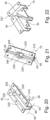
- Figure 21 shows a perspective view of the wall 30 in a variant to that shown in Figure 20 Deviating from this, the second and fourth wall region 220, 230 is longer in the longitudinal direction (y-direction) than in Figure 20 .
- the second wall region 220 and the fourth wall region 230 form a slot-shaped widening 235.
- the wall 30 has a second recess 240 in the wall base 60 in the longitudinal direction at the level of the second and fourth wall regions 220, 230.
- the second recess 240 is, for example, rectangular in shape and designed as a through-opening in the wall base 60.
- the second recess 240 is designed to receive a second fastening element 400 (not shown).
- the second fastening element 400 is described in detail in the Figures 31 and 32
- the second recess 240 can also be arranged in the wall section 50, 55.
- the second recess 240 can also correspond to an ejector 245 (dashed in Figure 21 shown) to press the cable harness 1010 out of the mold 15 from below after the cable harness 1010 has been produced in the mold 15. This can prevent damage to the cable harness 1010, in particular to the sheathing 1030, since the sheathing 1030 is essentially only subjected to a compressive load and not a tensile load by the ejector 245.
- the ejector 245 can bear directly against the sheathing 1030 or be attached to the second fastening element 400. If no second fastening element 400 is inserted into the second recess 240 during the production of the cable harness 1010, the mold space 40 is open downwards via the second recess.
- Figure 22 shows a perspective view of the mold 15 in a further embodiment.
- the wall 30 is similar to that shown in the Figures 20 and 21 shown wall 30. Deviating from this, the wall 30 delimits several mold spaces 45, which open into one another at a common area 241.
- the wall 30 can also be designed differently. Due to the opening of the mold cavities 45 in the common area, individual cable bundles 1020 and/or cables 1025 of the cable harness 1010 can be easily branched or combined in the mold 15.
- Figure 23 shows a longitudinal section through the mold 15 in a further embodiment.
- the mold 15 is similar to the one shown in the Figures 9A to 22 shown form 15.
- the wall base 63 and/or the wall section 55, 60 has a first wall surface section 250, a second wall surface section 255, and a wall surface transition section 260.
- the wall surface transition section 260 is arranged in the longitudinal direction between the first wall surface section 250 and the second wall surface section 255.
- the first wall surface section 250 is arranged lower than the second wall surface section 255.
- the first wall surface section 250 and the second wall surface section 255 are arranged in planes that are preferably arranged parallel and offset from one another.
- the wall surface transition section 260 is arranged at an angle to the first wall surface section 250 and the second wall surface section 255.
- the inclination of the wall surface transition section 260 advantageously has an angle ⁇ 2 , wherein the angle ⁇ 2 has a value that is less than 45°, in particular less than 30°, in particular less than 20°, in particular less than 15°, in particular less than 10°.
- the sheathing section 1400, 1405 and the transition section 1410 of the cable harness 1010 can be formed by the wall surface section 250, 255 and the wall surface transition section 260.
- Figure 24 shows a perspective view of a mold 15 in another embodiment.
- Form 15 is similar to that shown in the Figures 9A to 23 shown form 15. Deviating from this, the wall surface 61, 62 corresponds to the shape of the profile 1500 of the Figure 6 shown wiring harness 1010 is wave-shaped.
- Figure 25 shows a perspective view of a mold 15 in another embodiment.
- the mold 15 is similar to that shown in Figure 24 shown form 15, wherein the wall surface 61, 62 corresponding to the shape of the profile 1500 of the in Figure 7 shown wiring harness 1010 is wave-shaped.
- Figure 26 shows a perspective view of a mold in another embodiment.
- Form 15 is similar to that in Figure 24 and Figure 25 shown form 15, wherein the wall surface 61, 62 corresponding to the shape of the profile 1500 of the in Figure 8 shown wiring harness 1010 is rib-shaped.
- Figure 27 shows a perspective view of the first fastening element 200 according to a first embodiment.
- the first fastening element 200 has a fastening plate 300, a first fastening bracket 305, and a second fastening bracket 310.
- the first fastening bracket 305 and the second fastening bracket 310 are arranged on the fastening plate 300 at a distance from one another in the longitudinal direction.
- the fastening plate 300 is flat.
- the fastening plate 300 can also be curved.
- the fastening plate 300 rests against the wall surface 61, 62 and/or the wall base 63 with a side surface 315 facing away from the fastening bracket 305, 310.
- the fastening bracket 305, 310 has at least one laterally arranged contact surface 311, 312, which preferably rests against the wall surface 61, 62 assigned to it.
- the first fastening bracket 305 has a first insertion opening 330
- the second fastening bracket 310 has a second insertion opening 335.
- the first insertion opening 330 opens into the third recess 320.
- the second insertion opening 335 opens into the fourth recess 325.
- the insertion openings 330, 335 are arranged in the transverse direction (X-direction) on opposite sides of the respective fastening bracket 305, 310.
- the insertion opening 330, 335 can preferably enclose a 90° angle segment. This ensures stable fixation and positioning of the cable bundle 1020 and/or one or more cables 1025 of the cable bundle 1020 by means of the first fastening element 200 in the molding space 45.
- Figure 28 shows a perspective view of a first fastening element 200 according to a second embodiment.
- the first fastening element 200 is similar to that shown in Figure 27 shown embodiment of the first fastening element 200.
- the fastening bracket 305, 310 is preferably designed in a hook-like manner.
- the first fastening bracket 305 has a first bracket section 340 and a second bracket section 345.
- the first bracket section 340 is, for example, designed perpendicular to the fastening plate 300.
- the second bracket section 345 is perpendicular to the first bracket section 340 and, for example, parallel to the fastening plate 300.
- the second fastening bracket 310 is preferably designed identically to the first fastening bracket 305.
- the second fastening bracket 310 is arranged offset in the longitudinal direction (y-direction) from the first fastening bracket 305.
- the second bracket section 345 of the second fastening bracket 310 extends in the direction of the second bracket section 345 of the first fastening bracket 305 (x-direction) and is preferably arranged parallel to the first fastening bracket 305.
- the second bracket portion 345 may be wedge-shaped on a side facing the fastening plate 300.
- Figure 29 shows a perspective view of a first fastening element 200 according to a third embodiment.
- the first fastening element 200 is similar to that in Figure 28 shown first fastening element 200.
- the second bracket section 345 of the first and/or second bracket section 305, 310 is arranged at an angle to the fastening plate 300.
- the second bracket section 345 extends obliquely downwards towards the fastening plate 300.
- an angle between the first bracket section 340 and the second bracket section 345 is less than 90°.
- a support section 350 is provided between the first bracket section 340 and the fastening plate 300.
- the support section 350 has a support surface 355, which is preferably designed to correspond to the cable bundle 1020 and/or one or more cables 1025 of the cable bundle and is, for example, rounded, on a side facing the second bracket section 345.
- the cable bundle 1020 can be particularly well fixed in the molding space 45 by the fastening brackets 305, 310.
- Figure 30 shows a perspective view of a first fastening element 200 according to a fourth embodiment.
- the first fastening element 200 is similar to that in Figure 28 shown first fastening element 200. Deviating from this, the first fastening bracket 305 and the second fastening bracket 310 are on the same Height arranged. Furthermore, the second bracket section 345 of the first fastening bracket 305 tapers towards the second bracket section 345 of the second fastening bracket 310. The taper is preferably designed such that the second bracket section 345 is wedge-shaped. The second bracket section 345 of the second fastening section 310 is designed analogously to the second bracket section 345 of the first fastening bracket 305 and tapers down to the second bracket section 345 of the second fastening bracket 310.
- a second gap 360 is arranged between the second bracket section 345 of the first fastening bracket 305 and the second bracket section 345 of the second fastening bracket 310.
- the cable bundle 1020 or individual cables 1025 of the cable bundle 1020 can be inserted through the second gap 360, so that the cables 1025 of the cable bundle 1020 are encompassed by the fastening brackets 305, 310. This allows the cable bundle 12 to be positioned in a predefined position in the mold space 45.
- Figure 31 shows a perspective view of a second fastening element 400.
- the second engagement portion 415 preferably has a rib-shaped structure 430 on the outside.
- the second engagement portion 415 is designed to engage an opening 435 in the structure 1005 of the vehicle component 1000 of the motor vehicle. This allows the cable harness 11 to be particularly well fixed to the structure 1005.
- the second recess 240 (cf. Figure 21 ) corresponding to the second engagement portion 415 and the upper side of the support plate 405 is larger than the second recess 240.
- the fastening plate 405 simultaneously acts as a sealing element and delimits the molding space 45, for example, on the underside.
- a shoulder in the sheath 103 of the cable harness 1010 is reduced by the support plate 405 tapering outwardly.
- Figure 32 shows a perspective view of the second fastening element 400 according to a second embodiment.
- the second fastening element 400 is a combination of the Figure 29 shown first fastening element 200 and the one in Figure 31 shown second fastening element 400.
- the fastening plate 300 of the first fastening element 200 is formed in one piece and of the same material as the support plate 405 of the second fastening element 400.
- the first engagement section 410 is omitted by way of example.
- two first fastening elements 200 are arranged on the fastening plate 405 by way of example.
- the first fastening element 200 can ensure a position of the cable bundle 1020 and/or at least one cable 1025 in the molding space 45.
- the cable harness 1010 can be reliably fixed to the structure 1005 via the second engagement section 415.
- the support plate 405 preferably forms a materially bonded connection with the sheath 1030 of the cable harness 1010.
- Figure 33 shows a flowchart of a method for manufacturing the wiring harness 1010.
- Figure 34 shows a top view of the molding system 10 during a third process step and
- Figure 35 shows a sectional view along a Figure 34 shown section plane DD.
- a first method step 3000 the molding system 10 is prepared. Heating of the mold 15 is omitted, so that the mold 15 is essentially at room temperature. Furthermore, the introduction of a release agent into the mold cavity 45, in particular into the wall surface 61, 62 and/or the wall base 63, is omitted. This prevents the cables 1025 from coming into contact with the release agent and prevents a sheathing 1030 to be introduced from adhering to the cables 1025.
- a second method step 3005 which is optional, the first fastening element 200 and/or the second fastening element 400 are introduced into the molding space 45.
- the second engagement element 415 is inserted into the second recess 240 until the support plate 405 rests on the wall base 63 or the wall surface 61, 62.
- the first fastening element 200 is inserted such that it does not protrude from the mold 15 on the upper side and/or rests with the contact surface 311, 312 on the wall surface 61, 62 or preferably rests on the underside on the wall base 63.
- a third method step 3010 the individual cables 1025 of the cable bundle 1020 are inserted.
- the first holding element 65 and the second holding element 70 are reversibly deformed from a closed position in a first region 1605 by means of a means 1600 such that an insertion opening 1610 is formed between the holding elements 65, 70.
- the first and second holding elements 65, 70 are bent into the molding space 40 or away from the molding space 40.
- the insertion opening is delimited in the longitudinal direction by the means 1600 and in the transverse direction by the first and second holding elements 65, 70.
- the means 1600 can be a mechanical tool and/or fingers of a human hand and/or the cable 1025 to be inserted.
- the means 1600 protrudes, for example, in sections into the molding space 40 on the upper side.
- the holding elements 65, 70 are in the closed position.
- the first and/or second fastening element 200, 400 optionally secures a defined position of a predefined cable 1025 of the cable bundle 1020 relative to the other cables 1025 of the cable bundle 1020.
- the first and/or second fastening element 200, 400 can also position and secure the cable bundle 1020 in its position in the molding space.
- the defined arrangement of one or more cables 1025 in the cable bundle 1020 allows heating of the cable bundle 1020 in the cable harness 1010 to be precisely defined. In particular, overheating of the cable harness 1010 is thereby avoided. This prevents possible spontaneous combustion of the wiring harness 1010, short circuits or other irreversible damage to the wiring harness 1010.
- the holding device 40 prevents the cables 1025 from slipping out of the molding chamber 45. At least one of the cables 1025 of the cable bundle 1020 is inserted via the insertion opening 1610 by the means 1600 being moved longitudinally along the molding chamber 40 and, in parallel, the cable 1025 to be inserted is inserted into the molding chamber 40 from above via the insertion opening 1610. During the movement of the means 1600, the holding elements 65, 70 bend the means 1600 and form the insertion opening 1610 and, after passing the means 1600, move back into their closed position and cover the opening 35 of the molding space 40.
- the cables 1025 can be inserted particularly quickly, both manually and automatically, so that the cable harness 1010 can be manufactured particularly cost-effectively. Furthermore, inserting the cable 1025 in shape 15 with the holding device 40 is perceived as particularly ergonomic.
- a fourth method step 3015 the material of the casing 1030 is introduced into the mold cavity 45 via the opening 35 in a low-pressure process.
- the holding elements 65, 70 can be reversibly bent again from their closed position (for example, into the mold cavity 40 or away from the mold cavity 40) in order to introduce the material of the casing 1030 into the mold cavity.
- the second material is preferably first used to form the second layer 1205 (cf. Figure 3 ) and subsequently the first material of the first layer 1200 is introduced. Both the first and second materials are preferably thin-flowing when introduced. During the processing time of the material, the material sags in the direction of gravity and encloses the cables 1025 of the cable bundle 1020. The second material is accumulated at the wall base 63 and the second layer 1205 is formed. It is particularly advantageous here if the first material is applied to the second material when the second material is already curing and preferably the processing time of the second material has already elapsed.
- Form 15 is as in Figure 5 described, it is particularly advantageous if the material is first introduced above the first wall surface section 250 and, after filling the lower-lying first wall surface section 250, into the second wall surface section 255 above the second wall surface section 255. Finally, the material is introduced above the wall surface transition section 260. This procedure has the advantage that running off of the material from the second wall surface section 255 via the wall surface transition section 260 to the first wall surface section 250 is avoided.
- the material of the sheathing 1030 is applied in a wave-like manner in a plane parallel to the wall base 63 between the first wall section 50 and the second wall section 55. This ensures reliable embedding of the cables 1025 of the cable bundle 1020 in the sheathing 1030.
- the holding device 40 additionally prevents the cable bundle 1020 from being pushed out of the molding space 45 at the top and secures the cable bundle 1020 in the molding space 45. This ensures that the cable bundle 1020 is securely enclosed by the sheathing 1030.
- the first bulge 1036 can be easily formed through the first gap 120.
- the first bulge 130 is then formed, at least in sections, corresponding to the geometric configuration of the holding elements 65, 70 at the respective free end 100, 130 (cf. Figure 11A and Figure 12 ).
- the first bulge 1036 is produced by the material from the molding chamber 40 pressing against the underside 105, 125 of the brushes 66, 71 during foaming, and the brushes 66, 71 are thereby slightly bent upwards from the molding chamber 40 (in Figure 11B (shown symbolically in dashed lines).
- the signaling element 1038 corresponds to an imprint of the brushes 66, 71. If the gap 120 is arranged between the brushes 66, 71, the material of the casing 1030 va pushes into the gap 120, so that the first bulge 1036 laterally has a brush imprint of the brushes 66, 71.
- the design of the signaling element 1038 as a recess 1040 can also be produced particularly easily by means of the brushes 66, 71.
- a fifth method step 3020 the cover 155 is placed on the mold 15, wherein the cover 155 blocks the bending of the holding elements 65, 70 to a side facing away from the mold cavity 45. This ensures a particularly reliable geometric design of the casing 1030, in particular of the first bulge 1036, even when using foaming materials.
Landscapes
- Engineering & Computer Science (AREA)
- Mechanical Engineering (AREA)
- Manufacturing & Machinery (AREA)
- Architecture (AREA)
- Civil Engineering (AREA)
- Structural Engineering (AREA)
- Insulated Conductors (AREA)
- Details Of Indoor Wiring (AREA)
- Installation Of Indoor Wiring (AREA)
- Clamps And Clips (AREA)
- Moulds For Moulding Plastics Or The Like (AREA)
- Manufacturing Of Electric Cables (AREA)
- Insulating Bodies (AREA)
Description
- Die Erfindung betrifft einen Kabelbaum gemäß Patentanspruch 1eine Form zur Herstellung eines Kabelbaums gemäß Patentanspruch 2 und ein Formsystem gemäß Patentanspruch 8.
- Es sind Kabelbäume mit einzelnen Kabeln zur Verbindung unterschiedlicher Komponenten in einem Kraftfahrzeug bekannt. Dabei werden die Kabel auf einem Montagebrett gezogen und mittels eines Wickelbands umwickelt. Das Herstellen des Kabelbaums erfolgt im Wesentlichen manuell, sodass die Herstellung des Kabelbaums besonders kostenintensiv ist.
- So ist aus
EP 0 787 626 A2 undUS 2014/190742 A2 ein Kabelbaum bekannt. DieUS 2014/190742 A2 zeigt ferner auch eine Form zur Herstellung des Kabelbaums. - Es ist Aufgabe der Erfindung, einen verbesserten Kabelbaum, eine verbesserte Form und ein verbessertes Formsystem bereitzustellen.
- Diese Aufgabe wird mittels eines Kabelbaums für ein Kraftfahrzeug gemäß Anspruch 1 gelöst. Vorteilhafte Ausführungsformen sind in den abhängigen Ansprüchen angegeben. Es wurde erkannt, dass ein verbesserter Kabelbaum für ein Kraftfahrzeug dadurch bereitgestellt werden kann, dass der Kabelbaum ein Kabelbündel mit wenigstens zwei Kabeln und einer Ummantelung aufweist. Das Kabelbündel ist zumindest abschnittsweise in der Ummantelung eingebettet. Die Ummantelung weist einen Übergangsabschnitt auf. Der Übergangsabschnitt ist zwischen dem ersten Ummantelungsabschnitt und dem zweiten Ummantelungsabschnitt angeordnet. Der erste Ummantelungsabschnitt weist eine erste Seitenfläche und der zweite Ummantelungsabschnitt weist eine zweite Seitenfläche auf. Der Übergangsabschnitt weist eine Übergangsfläche auf, die eine Neigung gegenüber der ersten Seitenfläche und der zweiten Seitenfläche aufweist. Die Neigung weist einen Winkel auf, wobei der Winkel einen Wert aufweist, der kleiner als 45°, insbesondere kleiner als 30°, insbesondere kleiner als 20°, insbesondere kleiner als 15°, insbesondere kleiner als 10°, ist.
- Auf diese Weise kann auf ein aufwendiges Wickeln des Kabelbündels verzichtet werden.
- Ferner sorgt die Ummantelung dafür, dass der Kabelbaum besonders leicht geknickt und um enge Radien geführt werden kann. Auch sind die einzelnen Kabel des Kabelbündels durch die Ummantelung geschützt.
- In einer nicht beanspruchten Ausführungsform weist die Ummantelung außenseitig ein Signalisierungselement auf, wobei das Signalisierungselement parallel zum Kabelbündel zur Signalisierung einer Position des Kabelbündels geführt ist, wobei sich das Signalisierungselement sich vorzugsweise im Wesentlichen über die gesamte Längserstreckung der Ummantelung erstreckt, wobei das Signalisierungselement zumindest abschnittsweise korrespondierend zu einer geometrischen Ausgestaltung einer Halteeinrichtung einer Form ausgebildet ist. Mittels der ersten Ausbuchtung kann einfach die Ausrichtung des Kabelbündels in der Ummantelung signalisiert werden, sodass der Kabelbaum besonders schnell in dem Kraftfahrzeug verlegt werden kann.
- In einer nicht beanspruchten Ausführungsform weist das Signalisierungselement eine erste Ausbuchtung auf, wobei die erste Ausbuchtung wulstartig ausgebildet ist, und/oder wobei das Signalisierungselement außenseitig der Ummantelung eine Vertiefung aufweist. Dadurch kann bei einer Reparatur des Kabelbaums das Kabelbündel besonders schnell in der Ummantelung aufgefunden werden kann.
- In einer nicht beanspruchten Ausführungsform erstreckt sich die erste Ausbuchtung im Wesentlichen über eine gesamte Längserstreckung der Ummantelung.
- In einer nicht beanspruchten Ausführungsform weist der Kabelbaum ein erstes Befestigungselement auf. Das erste Befestigungselement ist zumindest abschnittsweise in der Ummantelung eingebettet. Das erste Befestigungselement ist ausgebildet, wenigstens eines der Kabel des Kabelbündels in einer vordefinierten Position zu halten. Auf diese Weise kann eine Erwärmung des Kabelbaums definiert festgelegt werden, sodass auch eine lokale Überhitzung des Kabelbaums zuverlässig vermieden wird. Dadurch kann eine irreversible Beschädigung des Kabelbaums auf einfache Weise vermieden werden.
- In einer nicht beanspruchten Ausführungsform weist der Kabelbaum ein zweites Befestigungselement auf. Das zweite Befestigungselement weist einen ersten Abschnitt, der in die Ummantelung eingebettet ist, auf. Das zweite Befestigungselement weist ferner einen zweiten Abschnitt auf, der ausgebildet ist, in ein Fahrzeugbauteil des Kraftfahrzeugs einzugreifen, um den Kabelbaum an dem Fahrzeugbauteil zu befestigen.
- In einer nicht beanspruchten Ausführungsform weist die Ummantelung eine erste Schicht, eine zweite Schicht und vorzugsweise eine dritte Schicht auf, wobei das Kabelbündel in der ersten Schicht eingebettet ist, wobei die erste Schicht einen ersten Werkstoff und die zweite Schicht einen zweiten Werkstoff aufweist, wobei vorzugsweise der zweite Werkstoff eine unterschiedliche, vorzugsweise eine größere, Elastizität als der erste Werkstoff aufweist, wobei vorzugsweise die zweite Schicht rechteckförmig ausgebildet ist oder eine Rippenstruktur aufweist, wobei vorzugsweise die zweite Schicht auf einer der ersten Schicht zugewandten Seite eine mit einer vordefinierten Oberflächenstruktur versehene Oberfläche aufweist, wobei vorzugsweise die zweite Schicht auf einer der ersten Schicht abgewandten Seite eine plan ausgebildet ist, wobei vorzugsweise die dritte Schicht auf einer der ersten Schicht abgewandten Seite der zweiten Schicht angeordnet ist, wobei die dritte Schicht wenigstens einen Werkstoff aufweist, wobei der dritte Werkstoff einen Klebstoff und/oder eine dritte Elastizität aufweist, die unterschiedlich, vorzugsweise geringer ist, als die erste und/oder zweite Elastizität. Dadurch kann die zweite Schicht als Schutz für das Kabelbündel dienen, sodass eine mögliche Beschädigung des Kabelbündels, beispielsweise durch scharfe Kanten einer Karosserie des Fahrzeugs, vermieden wird.
- In einer nicht beanspruchten Ausführungsform ist die erste Schicht in Richtung quer zu dem Kabelbündel schlanker ausgebildet ist als die zweite Schicht, wobei die erste Schicht ausgebildet ist eine Einbuchtung eines Fahrzeugbauteils einzugreifen, wobei vorzugsweise die erste Schicht einen trapezförmigen Querschnitt und die zweite Schicht eine im Wesentlichen rechteckförmigen Querschnitt aufweist.
- In einer nicht beanspruchten Ausführungsform weist die Ummantelung eine zweite Ausbuchtung auf, wobei der Kabelbaum durch eine Durchführung in einem Fahrzeugbauteil durchführbar ist, wobei die zweite Ausbuchtung geneigt zu einer Längserstreckung des Kabelbündels sich erstreckt, wobei die zweite Ausbuchtung ausgebildet ist, zumindest abschnittsweise eine vorzugsweise fluiddichte Abtrennung zwischen zwei Räumen eine des Fahrzeugbauteils auszubilden, wobei die zweite Ausbuchtung eine Ausbuchtungskontur aufweist, wobei die zweite Ausbuchtung ausgebildet ist, die Ausbuchtungskontur an eine Durchführungskontur der Durchführung zu pressen, um eine im Wesentlichen fluiddichte Abtrennung zwischen den Räumen bereitzustellen.
- In einer nicht beanspruchten Ausführungsform weist die Ummantelung eine zweite Ausbuchtung auf, wobei die zweite Ausbuchtung geneigt zu einer Längserstreckung des Kabelbündels sich erstreckt, wobei die zweite Ausbuchtung ausgebildet ist, zumindest abschnittsweise eine vorzugsweise fluiddichte Abtrennung zwischen zwei Räumen eine des Fahrzeugbauteils auszubilden, wobei die zweite Ausbuchtung eine Ausbuchtungskontur aufweist, wobei die zweite Ausbuchtung ausgebildet ist, die Ausbuchtungskontur an eine Einbuchtungskontur einer Einbuchtung eines Fahrzeugbauteils zu pressen um reibschlüssige Verbindung zwischen der Einbuchtung und der zweiten Aussparung bereitzustellen und den Kabelbaum in der Einbuchtung reibschlüssig zu befestigen. Dadurch kann der Kabelbaum besonders einfach in dem Kraftfahrzeug befestigt werden.
- Erfindungsgemäss weist die Ummantelung einen ersten Ummantelungsabschnitt und einen zweiten Ummantelungsabschnitt auf. Der erste Ummantelungsabschnitt weist eine erste Quererstreckung zu einer ersten Längserstreckungsrichtung des ersten Ummantelungsabschnitts auf. Der zweite Ummantelungsabschnitt weist eine zweite Quererstreckung zu einer zweiten Längserstreckung des zweiten Ummantelungsabschnitts auf. Die erste Quererstreckung ist größer als die zweite Quererstreckung.
- Die Aufgabe wird aber auch mittels einer Form zur Herstellung des oben beschriebenen Kabelbaums gemäß Patentanspruch 2 gelöst. Vorteilhafte Ausführungsformen sind in den abhängigen Ansprüchen angegeben.
- Es wurde erkannt, dass eine verbesserte Form zur Herstellung eines Kabelbaums dadurch bereitgestellt werden kann, dass die Form eine Wandung und eine Öffnung aufweist. Die Wandung begrenzt zumindest seitlich einen Formraum. Der Formraum grenzt oberseitig an die Öffnung an. Die Wandung einen ersten Wandungsflächenabschnitt, einen zweiten Wandungsflächenabschnitt und einen Wandungsflächenübergangsabschnitt auf, wobei der erste Wandungsflächenabschnitt vorzugsweise tiefer als der zweite Wandungsflächenabschnitt angeordnet ist, wobei zwischen dem ersten Wandungsflächenabschnitt und dem zweiten Wandungsflächenabschnitt der Wandungsflächenübergangsabschnitt angeordnet ist, wobei der Wandungsflächenübergangsabschnitt geneigt gegenüber dem ersten Wandungsflächenabschnitt und dem zweiten Wandungsflächenabschnitt angeordnet ist, wobei die Neigung vorzugsweise einen Winkel aufweist, wobei der Winkel einen Wert aufweist, der kleiner als 45°, insbesondere kleiner als 30°, insbesondere kleiner als 20°, insbesondere kleiner als 15°, insbesondere kleiner als 10°, ist. Dadurch wird eine Rissbildung im Kabelbaum am Übergang zwischen dem ersten Wandungsummantelungsabschnitt und dem zweiten Wandungsummantelungsabschnitt vermieden.
- Durch die nach oben geöffnete Form können die Kabel besonders leicht in der Herstellung des Kabelbaums verlegt werden, ohne dass diese um Stifte gezogen werden müssen. Dadurch kann der Kabelbaum besonders schnell hergestellt werden. Ferner können die Kabel auch automatisiert mittels eines Roboters verlegt werden, sodass die Fertigungskosten durch die Automatisierung weiter reduziert sind.
- In einer nicht beanspruchten Ausgestaltung weist die Form eine Halteeinrichtung auf. Die Halteeinrichtung ist an der Wandung angeordnet und deckt zumindest abschnittsweise die Öffnung ab, wobei die Halteinrichtung plattenartig und/oder bürstenartig ausgebildet ist, wobei die Halteeinrichtung einen Werkstoff aufweist, der reversibel elastisch verformbar ist und die Halteeinrichtung wenigstens um 70°, vorzugsweise um 90° reversibel, vorzugsweise in den Formraum, biegbar ist. Dadurch wird vermieden, dass die in den Formraum eingelegten Kabel ungewollt herausrutschen können. Auch wird ein Aufschwimmen der Kabel im Formraum beim Schäumen der Ummantelung vermieden.
- Besonders von Vorteil ist hierbei, wenn die Wandung einen Wandungsgrund aufweist, wobei die Halteeinrichtung zumindest abschnittsweise parallel zum Wandungsgrund angeordnet ist.
- Erfindungsgemäss weist die Wandung einen ersten Wandungsabschnitt und einen zweiten Wandungsabschnitt auf. Der erste Wandungsabschnitt gegenüberliegend zum zweiten Wandungsabschnitt angeordnet ist, wobei die Halteeinrichtung ein erstes Halteelement und ein zweites Halteelement umfasst, wobei an dem ersten Wandungsabschnitt das erste Haltelement und an dem zweiten Wandungsabschnitt das zweite Halteelement angeordnet sind, wobei das erste Haltelement und das zweite Haltelement mit jeweils einem freien Ende über der Öffnung enden und den Formraum zumindest abschnittweise verschließen, wobei vorzugsweise der erste Wandungsabschnitt und/oder der zweite Wandungsabschnitt zumindest abschnittsweise wellenförmig profiliert ist.
- In einer nicht beanspruchten Ausführungsform sind die freien Enden der Halteelemente beabstandet zueinander angeordnet, und/oder sind die Halteeinrichtungen überlappend über der Öffnung angeordnet.
- In einer nicht beanspruchten Ausführungsform weist der erste Wandungsabschnitt einen ersten Wandungsbereich und einen zweiten Wandungsbereich auf, wobei der erste Wandungsbereich im Wesentlichen parallel zum zweiten Wandungsabschnitt angeordnet ist, wobei der zweite Wandungsbereich in eine vom zweiten Wandungsabschnitt abgewandte Richtung vom ersten Wandungsbereich versetzt verläuft, sodass der Formraum eine Verbreiterung aufweist, wobei der zweite Wandungsbereich korrespondierend zur ersten Ausbuchtungskontur und/oder zur zweiten Ausbuchtungskontur ausgebildet ist.
- In einer nicht beanspruchten Ausführungsform ist in der Wandung eine Aussparung vorgesehen, wobei die Aussparung als Durchgangsöffnung ausgebildet ist und in einem Wandungsboden der Form angeordnet ist, wobei der Wandungsboden den Formraum unterseitig begrenzt, wobei die Aussparung ausgebildet ist, zumindest abschnittsweise das erste und/oder zweite Befestigungselement des Kabelbaums aufzunehmen, und/oder wobei ein Auswerfer zur Entnahme des Kabelbaums aus der Form ausgebildet ist, die Aussparung zu durchgreifen, wobei die Aussparung vorzugsweise korrespondierend zu dem Auswerfer ausgebildet ist. Dadurch kann der Kabelbaum besonders leicht und maschinell aus der Form entnommen werden.
- In einer nicht beanspruchten Ausführungsform ist in der Wandung eine Aussparung vorgesehen, wobei die Aussparung ausgebildet ist, zumindest abschnittsweise das erste und/oder das zweite Befestigungselement des Kabelbaums aufzunehmen.
- In einer weiteren Ausführungsform sind der erste Wandungsflächenabschnitt und der zweite Wandungsflächenabschnitt in zwei parallel zueinander angeordnete Ebenen angeordnet.
- In einer nicht beanspruchten Ausführungsform ist die Halteeinrichtung abschnittsweise unterbrochen und/oder durchgängig der Wandung folgend ausgebildet.
- In einer weiteren Ausführungsform weist die Halteeinrichtung als Werkstoff Silikon auf. Zusätzlich oder alternativ weist die Wandung wenigstens einen der folgenden Werkstoffe auf: Polytetraflourid, Polyoxymethylen.
- Diese Werkstoffe weisen gegenüber dem Werkstoff der Ummantelung eine besonders geringe Oberflächenspannung auf, sodass eine zuverlässige Entformung des Kabelbaums nach dem Aushärten der Ummantelung sichergestellt ist. Insbesondere wird auch gewährleistet, durch die Verwendung der Werkstoffe für die Wandung, dass eine hohe Anzahl von Kabelbäumen mit der Form hergestellt werden können, ohne dass zusätzlich weitere Reinigungs- oder Wiederaufbereitungsschritte zur Herstellung der ursprünglichen Form notwendig sind.
- In einer nicht beanspruchten Ausführungsform weist die Wandung eine dem Formraum zuwandte Wandfläche auf, wobei die Wandfläche zumindest abschnittsweise laserpoliert ist. Mittels des Laserpolierens werden möglicherweise in der Wandfläche vorhandene Riefen, die insbesondere dadurch entstehen, dass der Formraum in die Form gefräst wird, gemildert, sodass die Entformung und die Entnahme des Kabelbaums aus der Form zuverlässig gewährleistet ist.
- In einer nicht beanspruchten Ausführungsform ist die Wandung zumindest abschnittsweise wellenförmig und/oder rippenförmig und/oder plan profiliert. Dadurch kann der Kabelbaum auf einfache Weise optimal an die geometrischen Randbedingungen in dem Fahrzeug angepasst werden.
- In einer weiteren Ausführungsform ist an einem Längsende der Wandung ein Dichtelement angeordnet, um ein Austreten der Ummantelung aus dem Formraum zumindest teilweise zu unterbinden.
- In einer nicht beanspruchten Ausführungsform weist die Form ein erstes Formteil und ein zweites Formteil auf. Das erste Formteil weist an einem Längsende ein erstes Eingriffselement auf. Das zweite Formteil weist an einem dem Längsende des ersten Formteils zugewandten Längsende des zweiten Formteils eine korrespondierend zum ersten Eingriffselement ausgebildete erste Aufnahme auf. Das erste Eingriffselement greift in die erste Aufnahme ein und verbindet formschlüssig das erste Formteil mit dem zweiten Formteil, wobei das Eingriffselement und die Aufnahme derart zueinander ausgebildet sind, dass ein Abziehen in Längsrichtung durch den Eingriff des Eingriffselements in die Aufnahme blockiert ist, wobei vorzugsweise das Eingriffselement und das erste Formteil einstückig und materialeinheitlich ausgebildet sind. Auf diese Weise kann die Form besonders leicht erweitert oder angepasst werden.
- In einer weiteren Ausführungsform ist die Form ausgebildet, an einem Montagebrett eines Formsystems befestigt zu werden.
- Die Aufgabe wird aber auch durch ein Formsystem gemäß Patentanspruch 8 gelöst.
- Es wurde erkannt, dass ein verbessertes Formsystem dadurch bereitgestellt werden kann, dass das Formsystem eine Form und ein Montagebrett umfasst, wobei die Form wie oben beschrieben ausgebildet ist, wobei die Form auf einer einem Montagebrett zugewandten Seite ein weiteres Eingriffselement und das Montagebrett auf einer der Form zugewandten Seite wenigstens ein Rasterfeld mit mehreren weiteren Aufnahmen aufweist, oder wobei die Form auf einer dem Montagebrett zugewandten Seite eine weitere Aufnahme und das Montagebrett auf einer der Form zugewandten Seite ein Rasterfeld mit mehreren weiteren Eingriffselementen aufweist, wobei das weitere Eingriffselement und die weitere Aufnahme korrespondierend zueinander angeordnet sind, wobei das weitere Eingriffselement in eine der weiteren Aufnahme eingreift und das Montagebrett formschlüssig reversibel lösbar mit der Form verbindet, wobei die anderen weiteren Aufnahmen des Rasterfelds frei bleiben oder wobei eines der weitere Eingriffselemente in die weiteren Aufnahme eingreift und das Montagebrett formschlüssig reversibel lösbar mit der Form verbindet, wobei die anderen weiteren Eingriffselement des Rasterfelds frei bleiben, wobei vorzugsweise das weitere Eingriffselement einstückig und materialeinheitlich mit der Form oder mit dem Montagebrett ausgebildet ist.
- Dadurch kann die Form besonders schnell auf dem Montagebrett montiert werden oder besonders schnell das Formsystem an einen unterschiedlich herzustellenden Kabelbaum angepasst werden.
- Nachfolgend wird die Erfindung anhand von Figuren näher erläutert. Dabei zeigen:
-
Figur 1A einen Ausschnitt eines Querschnitts durch ein Fahrzeugbauteil eines Kraftfahrzeugs gemäß einer ersten Ausführungsform; -
Figur 1B einen Ausschnitt auf eine Draufsicht auf das inFigur 1A gezeigte Fahrzeugbauteil; -
Figur 2 eine Schnittansicht durch ein Fahrzeugbauteil gemäß einer zweiten Ausführungsform; -
Figur 3A einen Ausschnitt eines Querschnitts durch ein Fahrzeugbauteil des Kraftfahrzeugs gemäß einer dritten Ausführungsform; -
Figuren 3B bis 3D zeigen jeweils einen Ausschnitt eines Querschnitts jeweils einer Weiterbildung des inFigur 3A gezeigten Fahrzeugbauteils; -
Figur 3E einen Längsschnitt durch eine Weiterbildung des inFigur 3A gezeigten Fahrzeugbauteils; -
Figur 4A einen Ausschnitte eines Querschnitts durch ein Fahrzeugbauteil des Kraftfahrzeugs gemäß einer vierten Ausführungsform; -
Figur 4B einen Ausschnitte eines Querschnitts durch eine Weiterbildung des inFigur 4A gezeigten Fahrzeugbauteils; -
Figur 5 einen Längsschnitt durch einen Kabelbaum; -
Figur 6 eine perspektivische Ansicht eines Kabelbaums in einer weiteren Ausführungsform; -
Figur 7 eine perspektivische Ansicht eines Kabelbaums in einer weiteren Ausführungsform; -
Figur 8 eine perspektivische Ansicht eines Kabelbaums in einer weiteren Ausführungsform; -
Figur 9A eine perspektivische Ansicht eines Formsystems zur Herstellung wenigstens eines in denFiguren 1 bis 8 gezeigten Kabelbaums; -
Figur 9B eine Draufsicht auf das inFigur 9A gezeigte Formsystem; -
Figur 10 eine perspektivische Ansicht des ersten Formteils der inFigur 9A und Figur 9B gezeigten Form gemäß einer ersten Ausführungsform; -
Figur 11A eine Schnittansicht durch die inFigur 10 gezeigte Form entlang einer inFigur 10 gezeigten Schnittebene A-A; -
Figur 11B eine Schnittansicht einer Variante der inFigur 10 gezeigten Form entlang der inFigur 10 gezeigten Schnittebene A-A; -
Figur 12 eine Schnittansicht durch ein erstes Formteil gemäß einer zweiten Ausführungsform entlang der inFigur 10 gezeigten Schnittebene A-A; -
Figur 13 eine perspektivische Ansicht eines ersten Formteils gemäß einer dritten Ausführungsform; -
Figur 14 einen Ausschnitt einer perspektivischen Ansicht der Form; -
Figur 15 eine perspektivische Ansicht einer Weiterbildung der in denFiguren 9A bis 14 gezeigten Form; -
Figur 16 eine perspektivische Ansicht einer Weiterbildung der in denFiguren 9A bis 15 gezeigten Form; -
Figur 17 einen Ausschnitt einer perspektivischen Ansicht einer Weiterbildung der inFigur 16 gezeigten Form; -
Figur 18 eine perspektivische Ansicht des ersten Formteils gemäß einer vierten Ausführungsform; -
Figur 19 eine perspektivische Ansicht der Form mit dem inFigur 18 gezeigten Formteil; -
Figur 20 eine perspektivische Darstellung der Wandung in einer Weiterbildung; -
Figur 21 eine perspektivische Darstellung der Wandung in einer Variante zu der inFigur 20 gezeigten Ausgestaltung; -
Figur 22 eine perspektivische Ansicht der Form in einer weiteren Ausführungsform; -
Figur 23 einen Längsschnitt durch die Form in einer weiteren Ausführungsform; -
Figur 24 eine perspektivische Ansicht einer Form in einer weiteren Ausführungsform; -
Figur 25 eine perspektivische Ansicht einer Form in einer weiteren Ausführungsform; -
Figur 26 eine perspektivische Ansicht einer Form in einer weiteren Ausführungsform; -
Figur 27 eine perspektivische Ansicht des ersten Befestigungselements gemäß einer ersten Ausführungsform; -
Figur 28 eine perspektivische Ansicht eines ersten Befestigungselements gemäß einer zweiten Ausführungsform; -
Figur 29 eine perspektivische Darstellung eines ersten Befestigungselements gemäß einer dritten Ausführungsform; -
Figur 30 eine perspektivische Ansicht eines ersten Befestigungselements gemäß einer vierten Ausführungsform; -
Figur 31 eine perspektivische Darstellung eines zweiten Befestigungselements; -
Figur 32 eine perspektivische Ansicht des zweiten Befestigungselements gemäß einer zweiten Ausführungsform; -
Figur 33 ein Ablaufdiagramm eines Verfahrens zur Herstellung des Kabelbaums; -
Figur 34 eine Draufsicht auf das Formsystem während eines dritten Verfahrensschritts; und -
Figur 35 eine Schnittansicht entlang einer inFigur 34 gezeigten Schnittebene D-D. - Es wird darauf hingewiesen, dass die
Figuren 1A bis 4B ,6 bis 22 ,24 bis 35 zur Erläuterung des allgemeinen Verständnis dienen.Figur 5 zeigt einen erfindungsgemäßen Kabelbaum 1010 undFigur 23 eine erfindungsgemäße Form 15. -
Figur 1A zeigt einen Ausschnitt eines Querschnitts durch ein Fahrzeugbauteil 1000 eines Kraftfahrzeugs gemäß einer ersten Ausführungsform. Das Fahrzeugbauteil 1000 weist eine Struktur 1005 und einen Kabelbaum 1010 auf. Die Struktur 1005 beispielsweise eine Karosserie, ein Tiefziehteil, ein Dachhimmel, ein Türpanel, ein Zwischenpanel, ein Schallschutzschott oder ein Cockpit sein. Die Struktur 1005 kann beispielsweise aus Blech oder Kunststoffhergestellt sein. Die Struktur 1005 kann aber auch eine Kunststoffstruktur, ein Teppich oder ähnliches sein. Die Struktur 1005 weist eine Anlagefläche 1015 auf. Die Anlagefläche 1015 ist dem Kabelbaum 1010 zugewandt. - Der Kabelbaum 1010 weist ein Kabelbündel 1020 mit mehreren Kabeln 1025 auf. Die Kabel 1025 dienen dazu, elektrische Signale oder einen elektrischen Strom zwischen zwei Punkten zu übertragen. Die Kabel 1025 sind etwa in gleicher Richtung verlaufend zueinander angeordnet. Dabei kann am jeweiligen Ende des Kabelbaums 1010 ein Verbindungssystem zur elektrischen Verbindung des Kabelbaums 1010 mit einem weiteren elektrischen Gerät vorgesehen sein. Die Kabel 1025 des Kabelbündels 1020 sind in einer Ummantelung 1030 des Kabelbaums 1010 eingebettet. Die Ummantelung 1030 weist außenseitig eine Seitenfläche 1035 mit einer Ummantelungskontur auf.
- Die Ummantelung 1030 weist vorzugsweise wenigstens einen der folgenden Werkstoffe auf: Polyurethan, Silikon, Schaum, geschlossenporigen Schaum, offenporigen Schaum, Silikonschaum, Polyurethanschaum. Der Kabelbaum 1010 liegt mit der Seitenfläche 1035 an der Anlagefläche 1015 an. Dabei kann zusätzlich zwischen der Anlagefläche 1015 und der Seitenfläche 1035 eine Klebschicht vorgesehen sein, um den Kabelbaum 1010 stoffschlüssig mit der Struktur 1005 zu verbinden.
- Der Querschnitt der Ummantelung 1030 ist dabei frei wählbar und vorzugsweise korrespondierend zu der geometrischen Ausgestaltung der Anlagefläche 1015 zu wählen. Dabei ist von besonderem Vorteil, wenn die Anlagekontur und die Ummantelungskontur abschnittsweise identisch sind, sodass ein besonders gutes flächiges Anliegen des Kabelbaums 1010 an der Struktur 1005 sichergestellt ist.
- Besonders von Vorteil ist, wenn die Ummantelung 1030 ein Signalisierungselement 1038 umfasst. Das Signalisierungselement 1038 umfasst eine erste Ausbuchtung 1036, vorteilhafterweise an einer Oberseite 1037 des Kabelbaums 1010, aufweist. Die erste Ausbuchtung 1036 ragt über die Oberseite 1037 hervor. Die erste Ausbuchtung 1036 ist vorzugsweise wulstartig ausgebildet und erstreckt sich vorzugsweise zumindest abschnittsweise parallel zum Kabelbündel 1020. Das Signalisierungselement 1038 kann mittig zu einer maximalen ersten Quererstreckung b1 angeordnet sein. Dadurch kann auf einfache Weise der Verlauf der Kabel 1025 des Kabelbündels 1020 signalisiert werden. Ferner kann mit dem Signalisierungselement 1038 eine vordefinierte Seite zum Einlegen des Kabelbaums 1010 in die Struktur 1005 signalisiert werden, sodass der Kabelbaum 1010 besonders schnell in der Montage des Kraftfahrzeugs montiert werden kann. Zusätzlich oder alternativ ist auch denkbar, dass das Signalisierungselement 1038 eine Vertiefung 1040 in der Oberseite 1037 umfasst (strichliert in
Figur 1A dargestellt). Die Vertiefung 1040 kann beispielsweise zur Signalisierung eines bestimmten Typs von Kabelbaum 1010 dienen. -
Figur 1B einen Ausschnitt auf eine Draufsicht auf das inFigur 1A gezeigte Fahrzeugbauteil 1000. - Das Signalisierungselement 1038 erstreckt sich im Wesentlichen über die gesamte Längserstreckung des Kabelbaums 1010. Dadurch kann besonders einfach eine Einlegeposition des Kabelbündels 1020 in der Ummantelung 1030 ermittelt werden. Dies ist insbesondere dann von Vorteil, wenn die Ummantelung 1030 besonders dick ausgebildet ist und das Kabelbündel 1025 in der Ummantelung weder ertastet noch optisch erkennbar ist.
-
Figur 2 zeigt eine Schnittansicht durch ein Fahrzeugbauteil 1000 gemäß einer zweiten Ausführungsform. Das Fahrzeugbauteil 1000 ist im Wesentlichen identisch zu dem in Figur 1A gezeigten Fahrzeugbauteil 1000 ausgebildet. Die Struktur 1005weist einen ersten Raum 1100 und einen zweiten Raum 1105 auf. Zwischen dem ersten Raum 1100 und dem zweiten Raum 1105 ist eine Trennwand 1110 vorgesehen. Die Trennwand 1110 weist eine Öffnung 1115 auf. Durch die Öffnung 1115 ist der Kabelbaum 1010 geführt. - Der Kabelbaum 1010 ist im Wesentlichen identisch zu dem in
Figur 1A und Figur 1B erläuterten Kabelbaum 1010 ausgebildet. Zusätzlich weist die Ummantelung 1030 des Kabelbaums 1010 eine zweite Ausbuchtung 1120 auf. Die zweite Ausbuchtung 1120 erstreckt sich quer zu einer Längserstreckung des Kabelbündels 1020. Die Ummantelung 1030 weist vorteilhafterweise zumindest im Bereich der zweiten Ausbuchtung 1120 einen weichelastischen Werkstoff auf. Die zweite Ausbuchtung 1120 weist eine Ausbuchtungskontur 1121 auf. Die zweite Ausbuchtung 1120 ist in der Öffnung 1115 angeordnet und verfüllt die Öffnung 1115. Vorzugsweise ist die zweite Ausbuchtung 1120 in die Öffnung 1115 eingedrückt/verpresst. Dadurch drückt die zweite Ausbuchtung 1120 die Ausbuchtungskontur 1121 umlaufend an eine Öffnungskontur 1122 der Öffnung 1115 und dichtet den ersten Raum 1100 vom zweiten Raum fluidisch ab. Ferner wird dadurch wird eine Schallübertragung zwischen dem ersten Raum 1100 und dem zweiten Raum 1105 durch die zweite Ausbuchtung 1120 vermieden. Dabei ist von besonderem Vorteil, wenn die zweite Ausbuchtung 1120 umlaufend um das Kabelbündel 1020 herum angeordnet ist. Dabei kann besonders vorteilhafterweise im Querschnitt die zweite Ausbuchtung 1120 dreiecksförmig ausgebildet sein. Dadurch kann auf den Einsatz einer Tülle in der Öffnung 1115 verzichtet werden. -
Figur 3A zeigt einen Ausschnitt eines Querschnitts durch ein Fahrzeugbauteil 1000 des Kraftfahrzeugs gemäß einer dritten Ausführungsform. Das Fahrzeugbauteil ist ähnlich zu dem inFiguren 1 und 2 gezeigten Fahrzeugbauteil 1000 ausgebildet. Abweichend dazu weist der Kabelbaum 1010 eine erste Schicht 1200 und eine zweite Schicht 1205 auf. Die zweite Schicht 1205 ist unterseitig zur ersten Schicht 1200 und zwischen der ersten Schicht 1200 und der Struktur 1005 angeordnet. In der ersten Schicht 1200 ist das Kabelbündel 1020 eingebettet. Dabei grenzt erste Ausbuchtung 1036 an die erste Schicht 1200 an. Die erste Schicht 1200 weist vorzugsweise einen ersten Werkstoff auf und die zweite Schicht 1205 weist vorzugsweise einen zweiten Werkstoff auf. Die erste Schicht 1200 und die zweite Schicht 1205 können auch einen identischen Werkstoff aufweisen. Der zweite Werkstoff kann dabei eine unterschiedliche Elastizität zum ersten Werkstoff aufweisen. So ist von Vorteil, wenn die Elastizität des zweiten Werkstoffs größer ist als die Elastizität des ersten Werkstoffs, dass ein Klappern des Kabelbündels 1020 durch die besonders elastischen Eigenschaften der zweiten Schicht 1205 an der Struktur 1005 vermieden werden kann. - Ferner ist von Vorteil, wenn die Elastizität des zweiten Werkstoffs der zweiten Schicht 1205 geringer ist als die Elastizität des ersten Werkstoffs, da dadurch die zweite Schicht 1205 eine Art Platte ausbildet, die das Kabelbündel 1020 wirksam vor möglichen Beschädigungen schützt.
- In der Ausführungsform ist die zweite Schicht 1205 im Querschnitt rechteckförmig. Auch sind andere Ausgestaltungen der zweiten Schicht 1205 denkbar. So kann beispielsweise die zweite Schicht 1205 auch halbkreisförmig, elliptisch, U-förmig, C-förmig, zylindrisch oder andersartig ausgebildet sein. Auch ist denkbar, dass die zweite Schicht 1205 anstatt der in
Figur 3 gezeigten planen Ausgestaltung in Längsrichtung des Kabelbaums 1010 eine Rippenstruktur aufweist. Dadurch kann der Kabelbaum 1010 besonders gut um einen Radius geführt werden und gleichzeitig ein hoher Schutz durch die zweite Schicht 1205 für das Kabelbündel 1020 sichergestellt werden. -
Figur 3B zeigt einen Ausschnitt eines Querschnitts einer Weiterbildung des inFigur 3A gezeigten Fahrzeugbauteils 1000. Der Kabelbaum 1010 ist im Wesentlichen identisch zu dem inFigur 3 gezeigtem Kabelbaum 1010 ausgebildet. Abweichend dazu weist die zweite Schicht 1200 eine definierte Oberflächenstruktur 1215 an einer zu der ersten Schicht 1200 zugewandten Oberfläche 1220 auf. Die Oberflächenstruktur 1215 ist beispielsweise wellenförmig ausgebildet. Dadurch wird die Größe der Oberfläche 1220 der zweiten Schicht 1205 vergrößert und ein Anhaften der ersten Schicht 1205 gegenüber der inFigur 3A gezeigten Ausgestaltung an der zweiten Schicht 1200 verbessert. -
Figur 3C zeigt einen Ausschnitt eines Querschnitts einer Weiterbildung des inFigur 3A gezeigten Fahrzeugbauteils 1000. Abweichend dazu ist die erste Schicht 1200 in Querrichtung zu dem Kabelbündel 1020 schlanker ausgebildet als die zweite Schicht 1205. -
Figur 3D zeigt einen Ausschnitt eines Querschnitts einer Weiterbildung des inFigur 3 gezeigten Fahrzeugbauteils 1000. Zusätzlich weist die Ummantelung 1030 eine dritte Schicht 1210 auf. Die dritte Schicht 1210 ist auf einer der ersten Schicht 1200 abgewandten Seite der zweiten Schicht 1205 angeordnet und mit dieser verbunden. Die dritte Schicht 1210 weist einen dritten Werkstoff mit einer dritten Elastizität auf. Die dritte Elastizität ist vorzugweise geringer als die erste Elastizität und/oder die zweite Elastizität. Vorzugsweise ist die dritte Schicht 1210 als Prallplatte oder als Klebschicht ausgebildet. Bei der Ausbildung als Prallplatte ist von Vorteil, dass durch die dritte Schicht 1210 eine Beschädigung des Kabelbündels 1020 vermieden werden kann und gleichzeitig Schwingungen durch die zweite Schicht 1205 besonders gut gedämpft werden können. In der Ausführungsform sind die Schichten 1200, 1205, 1210 beispielhaft rechteckförmig mit identischer Breite in einem Schichtstapel angeordnet. Die Schichten 1200, 1205, 1210 können auch unterschiedliche Breiten oder Ausgestaltungen aufweisen. -
Figur 3E zeigt einen Längsschnitt durch eine Weiterbildung des inFigur 3A gezeigten Fahrzeugbauteils 1000. In der zweiten Schicht 1200 ist eine Rippenstruktur 1225 vorgesehen. Die Rippenstruktur 1225 weist Rippen 1230 und zwischen in Längsrichtung den Rippen 1230 angeordnet Rippenausnehmungen 1235 auf, die in Längsrichtung die Rippen 1230 begrenzen. Die Rippenausnehmungen 1235 weisen jeweils einen Ausnehmungsgrund 1240 auf, der beabstandet durch zu den Kabel 1025 des Kabelbündels 1020 angeordnet ist. -
Figur 4A zeigt einen Ausschnitt eines Querschnitts durch ein Fahrzeugbauteil 1000 des Kraftfahrzeugs gemäß einer vierten Ausführungsform. Das Fahrzeugbauteil 1000 ist im Wesentlichen identisch zu dem inFiguren 1A bis 3E gezeigten Fahrzeugbauteil 1000 ausgebildet. Die Struktur 1005 weist eine nutartige Einbuchtung 1300 mit einer Einbuchtungskontur 1301 auf. Die Einbuchtung 1300 ist beispielhaft rechteckförmig ausgebildet. Die Einbuchtung 1300 kann beispielsweise während eines Pressvorgangs in die Struktur 1005 eingebracht werden. - Der Kabelbaum 1010 ist im Wesentlichen identisch zu der in den
Figur 3A gezeigten Ausführungsform ausgebildet. Der Kabelbaum 1010 ist in der Einbuchtung 1300 angeordnet. Dabei weist die Ummantelung 1030 die zweite Ausbuchtung 1120 auf. Die zweite Ausbuchtung 1120 ist vorzugsweise umfangsseitig, das Kabelbündel 1020 auf vorzugsweise drei Seiten umgreifend und vorzugsweise schichtartig ausgebildet. Die zweite Ausbuchtung 1120 weist eine Ausbuchtungskontur 1121 auf. Der Werkstoff der zweiten Ausbuchtung 1120 ist vorzugsweise elastisch und einstückig und materialeinheitlich mit dem Werkstoff der Ummantelung 1030. In nicht montiertem Zustand ist dabei vorzugsweise die Ausbuchtungskontur 1121 der zweiten Ausbuchtung 1120 größer als die Einbuchtungskontur der Einbuchtung 1300. - Wird der Kabelbaum 1010 montiert, so wird die zweite Ausbuchtung 1120 und deren Werkstoff zusammengedrückt, sodass die zweite Ausbuchtung 1120 ihre Ausbuchtungskontur 1121 an die Einbuchtungskontur der Einbuchtung 1300 andrückt, sodass der Kabelbaum 1010 über die zweite Ausbuchtung 1120 reibschlüssig mit der Einbuchtung 1300 des Fahrzeugbauteils 1000 verbunden ist. Dadurch kann der Kabelbaum 1010 besonders platzsparend in der Struktur 1005 des Fahrzeugbauteils 1000 untergebracht werden.
- Insbesondere ist hier von Vorteil, dass die Struktur 1005 angrenzend an die Einbuchtung 1300 eine Oberfläche 1310 aufweist, wobei die Oberseite 1037 des Kabelbaums 1010 im Wesentlichen übergangslos / stufenlos zu der Oberfläche 1310 ausgebildet sind. Vorzugsweise liegen die Oberseite 1037 und die Oberfläche der Struktur 1005 in einer gemeinsamen Ebene. Dabei kann bei dem Kabelbaum 1010 auf die zweite Ausbuchtung 1120 verzichtet werden, wobei in dieser Ausgestaltung der Kabelbaum 1010 die Einbuchtung 1300 im Wesentlichen vollständig verfüllt. Auch kann die zweite Ausbuchtung 1120 in Längsrichtung nur abschnittweise vorgesehen sein, in den übrigen Bereichen (ohne zweite Ausbuchtung 1120) ist hierbei beispielsweise die Ummantelung 1030 beabstandet zu der Einbuchtungskontur 1305 angeordnet.
-
Figur 4B zeigt einen Querschnitt durch eine Weiterbildung des inFigur 4A gezeigten Fahrzeugbauteils 1000. - Die in
Figur 4B gezeigte Ausgestaltung ist im Wesentlichen eine Kombination der inFigur 3C gezeigten Ausgestaltung des Kabelbaums 1010 mit der inFigur 4A gezeigten Ausgestaltung des Fahrzeugbauteils 1000. Abweichend dazu weist das Fahrzeugbauteil 1000 zusätzlich zur Struktur 1005 eine Haltestruktur 1006 auf, die oberseitig beabstandet zur Einbuchtung 1300 angeordnet ist. In die Einbuchtung 1300 greift nur die erste Schicht 1200 ein, während hingegen die zweite Schicht 1205 außerhalb der Einbuchtung 1300 zwischen der Haltestruktur 1006 und der Struktur 1005 angeordnet ist. Vorzugsweise drückt die Haltestruktur 1006 mit einer Haltekraft FH gegen die zweite Schicht 1205 und sichert so den Kabelbaum 1010 an der Struktur 1005. Die Haltestruktur 1006 kann an der Struktur 1005 befestigt sein. Auch kann die Haltestruktur 1006 eine andere Fahrzeugbaugruppe zu der Struktur sein. -
Figur 5 zeigt einen Längsschnitt durch einen Kabelbaum 1010. Die Ummantelung 1030 des Kabelbaums 1010 weist einen ersten Ummantelungsabschnitt 1400, einen zweiten Ummantelungsabschnitt 1405 und einen Übergangsabschnitt 1410 auf. Der Übergangsabschnitt 1410 ist in Längsrichtung des Kabelbaums 1010 zwischen dem ersten Ummantelungsabschnitt 1400 und dem zweiten Ummantelungsabschnitt 1405 angeordnet. Der erste Ummantelungsabschnitt 1400 weist eine erste Seitenfläche 1415 und der zweite Ummantelungsabschnitt 1405 eine zweite Seitenfläche 1420 auf. Die Seitenflächen 1415, 1420 sind vorzugweise parallel in zwei unterschiedlich zueinander versetzt angeordneten Ebenen angeordnet. Dabei sind die Seitenflächen 1415, 1420 beispielhaft plan ausgebildet. Auch eine andere Ausgestaltung der Seitenflächen 1415, 1420 ist denkbar. Der Übergangsabschnitt 1410 weist eine Übergangsfläche 1425 auf. Die Seitenflächen 1415, 1420 und die Übergangsfläche 1425 können unterseitig am Kabelbaum 1010, seitlich am Kabelbaum 1010 oder oberseitig am Kabelbaum 1010 angeordnet sein. Die Übergangsfläche 1425 ist geneigt gegenüber der ersten Seitenfläche 1415 und der zweiten Seitenfläche 1420 angeordnet. Die Neigung weist einen Winkel α1 auf, wobei der Winkel α1 einen Wert aufweist, der kleiner als 45°, insbesondere kleiner als 30°, insbesondere kleiner als 20°, insbesondere kleiner als 15°, insbesondere kleiner als 10° ist. Dadurch wird eine Rissbildung in der Ummantelung 1030 beim Übergang zwischen dem ersten Ummantelungsabschnitt 1400 und dem zweiten Ummantelungsabschnitt 1405 vermieden. Es ist auch denkbar, dass die Übergangsfläche 1425 anstatt der inFigur 5 gezeigten planen Ausgestaltung gekrümmt ausgebildet ist. Hierbei ist insbesondere eine konvexe oder eine konkave Krümmung denkbar. - Durch die versetzten Seitenflächen 1415, 1420 weist der erste Ummantelungsabschnitt 1400 die erste Quererstreckung b1 zu einer ersten Längserstreckungsrichtung des ersten Ummantelungsabschnitts 1400 und der zweite Ummantelungsabschnitt 1405 eine zweite Quererstreckung b2 zu einer zweiten Längserstreckungsrichtung des zweiten Ummantelungsabschnitts 1405 auf. Die erste Quererstreckung b1 ist dabei größer als die zweite Quererstreckung b2.
- Beispielhaft ist in
Figur 5 die erste Längserstreckungsrichtung identisch zur zweiten Längserstreckungsrichtung. Die erste Längserstreckungsrichtung kann auch unterschiedlich zur der zweiten Längserstreckungsrichtung sein und beispielsweise der Übergangsabschnitt 1410 gekrümmt ausgebildet sein. Diese Ausgestaltung des Kabelbaums 1010 hat den Vorteil, dass der Kabelbaum 1010 in seiner Breite flexibel an den an der Struktur 1005 zur Verfügung stehenden Bauraum angepasst werden kann. -
Figur 6 zeigt eine perspektivische Ansicht eines Kabelbaums 1010 in einer weiteren Ausführungsform. - Der Kabelbaum 1010 ist ähnlich zu dem in den
Figuren 1 bis 5 gezeigten Kabelbaum 1010 ausgebildet. Abweichend dazu ist die Seitenfläche 1035 mit einem beispielhaften wellenartigen Profil 1500 ausgebildet. Das Profil 1500 weist einen ersten Profilabschnitt 1505 und einen zweiten Profilabschnitt 1510 auf. Der erste Profilabschnitt 1505 ist beispielhaft in Längsrichtung breiter ausgebildet als der zweite Profilabschnitt 1510. Vorzugsweise ist der erste Profilabschnitt 1505 konkav ausgebildet und der zweite Profilabschnitt konvex. Der erste und der zweite Profilabschnitt 1505, 1510 wechseln sich in Längsrichtung ab. -
Figur 7 zeigt eine perspektivische Ansicht eines Kabelbaums 1010 in einer weiteren Ausführungsform;
Der Kabelbaum 1010 ist im Wesentlichen identisch zu dem inFigur 6 gezeigten Kabelbaum 1010 ausgebildet. Abweichend dazu sind der erste Profilabschnitt 1505 und der zweite Profilabschnitt 1510 identisch breit ausgebildet. -
Figur 8 zeigt eine perspektivische Ansicht eines Kabelbaums 1010 in einer weiteren Ausführungsform;
Der Kabelbaum 1010 ist im Wesentlichen identisch zu dem inFigur 6 gezeigten Kabelbaum 1010 ausgebildet. Abweichend dazu ist das Profil 1500 im Wesentlichen rechteckförmig, wobei der erste Profilabschnitt des inFigur 6 gezeigten Kabelbaums 1010 im Wesentlichen plan ausgebildet ist und der zweite Profilabschnitt 1510 als Einbuchtung in der Seitenfläche 1035 ausgebildet ist. -
Figur 9A zeigt eine perspektivische Ansicht eines Formsystems 10 zur Herstellung wenigstens eines in denFiguren 1 bis 8 gezeigten Kabelbaums 1010. - Das Formsystem 10 weist vorzugsweise eine Form 15 und ein Montagebrett 20 auf. Das Montagebrett 20 ist beispielhaft plan. Die Form 15 kann ein erstes Formteil 16 und wenigstens ein zweites Formteil 17 aufweisen, die jeweils an einem Längsende 18 aneinanderstoßen und mit einer Unterseite 19 auf einer Oberseite 25 des Montagebretts 20, vorzugsweise in einer gemeinsamen Ebene, angeordnet sind.
-
Figur 9B zeigt einen Ausschnitt einer Draufsicht auf das inFigur 9A gezeigte Formsystem 10. - Das Montagebrett 20 weist an der Oberseite 25 beispielhaft ein Rasterfeld 27 mit mehreren identisch zueinander ausgebildeten ersten Aufnahmen 142. Die erste Aufnahmen 142 sind in dem Rasterfeld 27 in einem regelmäßigen Muster angeordnet. Aus Übersichtlichkeitsgründen wurden nur einige der ersten Aufnahmen 142 in
Figur 9B dargestellt. -
Figur 10 zeigt eine perspektivische Ansicht des ersten Formteils 16 der inFigur 9A und Figur 9B gezeigten Form 15 gemäß einer ersten Ausführungsform. - Zur erleichterten Erläuterung der Form 15 wird im Folgenden auf ein Koordinatensystem 26 Bezug genommen. Das Koordinatensystem 26 ist vorzugsweise als Rechtssystem ausgebildet und weist eine x-Richtung (Quererstreckungsrichtung), eine y-Richtung (Längsrichtung) und eine z-Richtung (Höhe) auf.
- Die Form 15 weist eine Wandung 30, eine Öffnung 35 und eine Halteeinrichtung 40 auf. Die Wandung 30 begrenzt einen Formraum 45. In dem Formraum 45 werden das Kabelbündel 1020 und die Ummantelung 1030 in der Herstellung des Kabelbaums 1010 über die Öffnung 35 eingebracht. Die Öffnung 35 ist oberseitig angeordnet und grenzt an den Formraum 45 an. In der Ausführungsform ist beispielhaft der Formraum 45 mit einem rechteckförmigen Querschnitt ausgebildet. Der Formraum 45 kann auch andersartig ausgebildet sein und einen anderen Querschnitt aufweisen. So ist beispielsweise auch denkbar, dass der Formraum 45 (abschnittsweise) polygonförmig, dreiecksförmig, verrundet, kreisförmig und/oder elliptisch ausgebildet ist.
- Die Wandung 30 weist einen ersten Wandungsabschnitt 50, einen zweiten Wandungsabschnitt 55 und einen Wandungsboden 60 auf. Zwischen dem ersten Wandungsabschnitt 50 und dem zweiten Wandungsabschnitt 55 ist der Wandungsboden 60 angeordnet. Der erste Wandungsabschnitt 50 und der zweite Wandungsabschnitt 55 begrenzen seitlich den Formraum 45. Der Wandungsboden 60 begrenzt unterseitig den Formraum 45. Vorzugsweise oberhalb des Wandungsbodens 60 ist die Öffnung 35 angeordnet.
- Der erste Wandungsabschnitt 50 weist eine dem Formraum 45 zugewandte erste Wandungsfläche 61, der zweite Wandungsabschnitt 55 eine dem Formraum 45 zugewandte zweite Wandungsfläche 62 und der Wandungsboden 60 einen dem Formraum 45 zugewandten Wandungsgrund 63 auf. In der Ausführungsform sind beispielhaft die erste und zweite Wandungsfläche 61, 62 parallel geführt. Der Wandungsgrund 63 ist senkrecht zur ersten Wandungsfläche 61 und zur zweiten Wandungsfläche 62 angeordnet. Der Wandungsgrund 63 und/oder die Wandungsfläche 61, 62 können auch anders angeordnet sein. So kann die erste Wandungsfläche 61 schräg zur zweiten Wandungsfläche 62 angeordnet sein. Auch wäre denkbar, dass die erste Wandungsfläche 61 und die zweite Wandungsfläche 62 direkt aneinander angrenzen und auf den Wandungsboden 60 verzichtet wird, sodass beispielsweise der Formraum 45 einen dreiecksförmigen Querschnitt aufweist.
- Dabei ist von besonderem Vorteil, wenn wenigstens eine der Wandungsflächen 61, 62 und/oder der Wandungsgrund 63 zumindest abschnittsweise laserpoliert ist. Dadurch kann eine besonders hohe Oberflächengüte sichergestellt werden. Ferner werden Riefen und/oder Rillen, die beispielsweise dadurch entstehen, indem der Formraum 45 mittels eines Spanverfahrens in einen Grundkörper zur Herstellung der Form 15 eingebracht wird, durch das Laserpolieren zumindest teilweise aufgehoben werden. Dadurch wird eine besonders langzeitstabile Form 15 sichergestellt, mit der zahlreiche Kabelbäume 1010 ohne zusätzliche Vorbereitung der Form 15 hergestellt werden können.
- Im Gegensatz zur planen Ausgestaltung der Wandungsfläche 61, 62 und/oder des Wandungsgrunds 63 können auch die Wandungsfläche 61, 62 und/oder der Wandungsgrund 63 zumindest abschnittsweise wellenförmig und/oder rippenförmig profiliert sein.
- Die Halteeinrichtung 40 umfasst ein erstes Halteelement 65, ein zweites Halteelement 70, ein erstes Anpresselement 75, ein zweites Anpresselement 80 und ein erstes Befestigungsmittel 85. Das erste Halteelement 65 und das zweite Halteelement 70 sind beispielhaft symmetrisch zu einer Symmetrieebene 86, die vorzugsweise mittig durch den Formraum 45 verläuft, ausgebildet. Die Symmetrieebene 86 ist als YZ-Ebene vorzugsweise ausgebildet. Auch können das erste Halteelement 65 und das zweite Halteelement 70 unterschiedlich zueinander ausgebildet sein.
- Die Form 15 ist mittels eines zweiten Befestigungsmittels 135, das in der Ausführungsform beispielhaft wenigstens einen als erstes Eingriffselement beispielhaft ausgebildeten Stift 140 aufweist, mit dem Montagebrett 20 formschlüssig verbunden. Der Stift 140 ist dabei mit der Wandung 30 verbunden und greift mit einem freien Längsende 141 in die korrespondierend zum Stift 140 ausgebildete erste Aufnahme 142 des Rasterfelds 27 in das Montagebrett 20 ein. Um eine besonders einfache Montage der Form 15 auf dem Montagebrett 20 sind hierzu vorzugsweise mehrere korrespondierend zu den ersten Aufnahmen 142 und identisch zueinander ausgebildete Stifte 140 vorgesehen, die mit der Wandung 30 verbunden sind. Die Stifte 140 greifen je nach Ausrichtung der Form 15 in jeweils eine erste Aufnahme 142 des Rasterfelds 27 ein, während hingegen die anderen ersten Aufnahmen 142 des Rasterfelds 27 frei bleiben. Dabei kann der Eingriff zusätzlich kraftschlüssig gesichert werden, um ein ungewolltes Abfallen der Form 15 vom Montagebrett 20, beispielsweise wenn das Formsystem 10 gekippt werden sollte, zu verhindern. Dies kann beispielsweise dadurch erzielt werden, dass der Stift 140 und die Aufnahme 142 als Übergangspassungssystem oder als Presspassungssystem ausgebildet sind.
- Auch kann das zweite Befestigungsmittel 135 andersartig ausgebildet sein. Insbesondere ist hierbei auch denkbar, dass das zweite Befestigungsmittel 135 als Schraubsystem ausgebildet ist.
- Die erste Aufnahme kann auch an der Unterseite 19 des Formteils 16, 17 angeordnet sein. An der Oberseite des Montagebretts 20 weist das Montagebrett 20 vorzugsweise eine Vielzahl als erste Eingriffselemente ausgebildete Stifte 140 auf.
- Alternativ kann das Rasterfeld 27 statt der ersten Aufnahmen 142 die als erste Eingriffselemente ausgebildeten Stifte 140 aufweisen, die in sich in Richtung der Form 15 erstrecken. In der Alternative ist die erste Aufnahme 142 an der Form 15 vorzugsweise in der Wandung 30 angeordnet. Je nach Ausrichtung der Form 15 greifen in montiertem Zustand der Form 15 an dem Montagebrett 20 jeweils einige der Stifte 140 des Rasterfelds 27 in die erste Aufnahmen 142 ein und befestigen wie oben beschrieben die Form 15 an dem Montagebrett 20 reversibel. Die anderen Stifte 140, die nicht in die erste Aufnahme 142 eingreifen bleiben (zumindest umfangsseitig) frei und/oder sind zumindest abschnittsweise (oberseitig) durch die Form 15 bedeckt.
-
Figur 11A zeigt eine Schnittansicht durch die inFigur 10 gezeigte Form 15 entlang einer inFigur 10 gezeigten Schnittebene A-A in einer Schließposition der Halteelemente 65, 70. - Das erste Halteelement 65 ist plattenartig ausgebildet und umfasst einen ersten Abschnitt 90 und einen zweiten Abschnitt 95. Das erste Halteelement 65 ist dabei mit einem ersten Abschnitt 90 oberseitig des ersten Wandungsabschnitts 50 angeordnet. Oberseitig des ersten Abschnitts 90 ist das erste Anpresselement 75 angeordnet. Das erste Anpresselement 75 ist mittels des ersten Befestigungsmittels 85 vorzugsweise kraftschlüssig mit dem ersten Wandungsabschnitt 50 verbunden. Dabei stellt das erste Befestigungsmittel 85 eine erste Verspannkraft FS1 bereit, mit der das erste Anpresselement 75 das erste Halteelement 65 an die Oberseite des ersten Wandungsabschnitts 50 presst. Dabei ist in der Ausführungsform beispielhaft das erste Anpresselement 75 genauso breit in X-Richtung wie der erste Wandungsabschnitt 50 ausgebildet. Dadurch kann ein zuverlässiges Anpressen des ersten Halteelements 65 durch das erste Anpresselement 75 sichergestellt werden. Ferner kann eine ungewollte Verformung des ersten Halteelements 65 vermieden werden.
- Ein erstes freies Ende 100 des ersten Halteelements 70 endet über der Öffnung 35. Mit einem zweiten Abschnitt 95, der an das erste freie Ende 100 des ersten Halteelements 65 angrenzt, bedeckt das erste Halteelement 65 oberseitig die Öffnung 35. Vorzugsweise kann der zweite Abschnitt 95 zumindest abschnittsweise keilförmig ausgebildet sein. Dabei ist von besonderem Vorteil, wenn eine erste Unterseite 105 des ersten Halteelements 65 im Wesentlichen plan ausgebildet ist und vom freien Ende 100 hin zum ersten Wandungsabschnitt 50 oberseitig das erste Halteelement 65 dicker (Z-Richtung) wird.
- Das zweite Halteelement 70 ist vorzugsweise gegenüberliegend auf gleicher Höhe, das heißt beispielhaft in einer gemeinsamen XY-Ebene, zu dem ersten Halteelement 65 angeordnet. Das zweite Halteelement 70 ist spiegelsymmetrisch zu der Symmetrieebene 86 angeordnet. Das zweite Halteelement 70 ist oberseitig des zweiten Wandungsabschnitts 55 angeordnet und weist einen dritten Abschnitt 110 und einen vierten Abschnitt 115 auf sowie ist beispielhaft plattenförmig ausgebildet. Mit dem dritten Abschnitt 110 liegt das zweite Halteelement 70 oberseitig des zweiten Wandungsabschnitts 55 an. Oberhalb des dritten Abschnitts 110 ist das zweite Anpresselement 80 angeordnet. Das erste Befestigungsmittel 85 stellt für das zweite Anpresselement 80 eine zweite Anpresskraft FS2 bereit, mit der das zweite Anpresselement 80 den zweiten Abschnitt 110 an die Oberseite des zweiten Wandungsabschnitts 55 presst. Dabei ist beispielhaft das zweite Anpresselement 80 genauso breit ausgebildet wie der zweite Wandungsabschnitt 55. Dabei begrenzen das erste Anpresselement 75 und das zweite Anpresselement 80 seitlich einen ersten Spalt 120, der genauso breit ist wie die Öffnung 35.
- Der vierte Abschnitt 115 grenzt an ein zweites freies Ende 130 des zweiten Halteelements 70 an. Der vierte Abschnitt 115 ist ebenso wie der zweite Abschnitt 95 keilförmig ausgebildet, wobei eine zweite Unterseite 125 des zweiten Halteelements 70 in einer gemeinsamen Ebene mit der ersten Unterseite 105 des ersten Halteelements 65 angeordnet ist. Das zweite freie Ende 130 endet über der Öffnung 35. Oberseitig verdickt sich der vierte Abschnitt 115 vom zweiten freien Ende 130 hin zum dritten Abschnitt 110.
- Der vierte Abschnitt 115 grenzt dabei an ein zweites freies Ende 130 des zweiten Halteelements 70 an.
- Das erste freie Ende 100 ist vorzugsweise zu dem zweiten freien Ende 130 des zweiten Halteelements 70 beabstandet angeordnet. Ein Abstand a zwischen dem ersten freien Ende 100 und dem zweiten freien Ende 130 ist dabei vorzugsweise zehnmal kleiner als eine Breite der Öffnung 35 (bezogen auf eine gemeinsame XZ-Ebene). Dadurch deckt die Halteeinrichtung (40) ausschließlich abschnittsweise die Öffnung 35 ab. Das erste freie Ende 100 und das zweite freie Ende 130 können auch in Berührkontakt aneinander liegen.
- Besonders günstig ist, wenn das Halteelement 65, 70 einen Werkstoff aufweist, der besonders elastisch und wenigstens um 90° reversibel, vorzugsweise in den Formraum 45, biegbar ist. Dabei ist von besonderem Vorteil, wenn das Halteelement 65, 70 als Werkstoff Silikon aufweist. Ferner kann dadurch die Halteeinrichtung 65, 70 der geometrischen Ausgestaltung des Wandungsabschnitts 50, 55 folgend ausgebildet werden.
-
Figur 11B zeigt eine Schnittansicht einer Variante der inFigur 10 gezeigten Form 15 entlang der inFigur 10 gezeigten Schnittebene A-A. - Die Form 15 ist im Wesentlichen identisch zu der in
Figur 11A gezeigten Ausgestaltung ausgebildet. Abweichend dazu sind das erste Halteelement 65 und das zweite Halteelement 70 bürstenartig ausgebildet. Dabei weist das erste Halteelement 65 eine erste Bürste 66 mit einer Vielzahl von Bürstenfasern 67 und das zweite Haltehalteelement 70 eine zweite Bürste 71 mit einer Vielzahl von zweiten Bürstenfasern 72 auf. - Dir Bürstenfasern 67, 72 erstrecken sich im Wesentlichen in Querrichtung. Dabei sind der zweite Abschnitt 95 und der vierte Abschnitt 115 breiter als eine halbe Breite der Öffnung 35 in Querrichtung (x-Richtung). Dadurch greifen die Bürsten 66, 71 in die jeweils gegenüberliegende Bürste 66, 71 ein und verschließen die Öffnung 35 oberseitig vollständig.
- Auch können die freien Enden 100, 130 wie in
Figur 11A gezeigt beabstandet zueinander angeordnet sein. -
Figur 12 zeigt eine Schnittansicht durch ein erstes Formteil 16 gemäß einer zweiten Ausführungsform entlang der inFigur 10 gezeigten Schnittebene A-A. - Die Form 15 ist ähnlich zu der in den
Figuren 9A bis 11 gezeigten Form 15 ausgebildet. Abweichend dazu sind abschnittsweise der zweite Abschnitt 95 und der vierte Abschnitt 115 der Halteelemente 65, 70 oberhalb der Öffnung 35 überlappend angeordnet. Dabei wird unter einer Überlappung verstanden, dass sich diese bei einer Projektion des zweiten Abschnitts 95 und des vierten Abschnitts 115 in eine gemeinsame XY-Ebene zumindest abschnittsweise überdecken. - Die Wandung 30 des ersten Formteils 16 ist einstückig und materialeinheitlich ausgebildet. Dabei weist vorteilhafterweise die Wandung 30 wenigstens einen der folgenden Werkstoffe auf: Polypropylen (PP), Polytetraflourid (PTFE), Polyethylen (PE), vorzugsweise Polyethylen mit stark verzweigten Polymerketten (PE-LD), Polyoxymethylen (POM). Zusätzlich oder alternativ ist auch denkbar, dass die Wandung 30 einen Werkstoff aufweist, der eine besonders niedrige Oberflächenspannung zu Polyurethan und/oder Silikon aufweist.
-
Figur 13 zeigt eine perspektivische Ansicht eines ersten Formteils 16 gemäß einer dritten Ausführungsform. - Das erste Formteil 16 ist ähnlich zu der in den
Figuren 10 bis 12 gezeigten Form 15 ausgebildet. Abweichend dazu weist das erste Formteil 16 gegenüber der inFigur 10 gezeigten Ausgestaltung eine vergrößerte Längserstreckung auf. - Die Halteeinrichtung 40 ist korrespondierend zu der vergrößerten Längserstreckung ausgebildet. Dabei ist zusätzlich, um das zweite Befestigungsmittel 135 oberseitig der Wandung 30 montieren zu können, jeweils eine erste Einbuchtung 145 in der Halteeinrichtung 4, vorzugsweise auf einer zur Öffnung 45 abgewandten Seite, vorgesehen. Dabei erstreckt sich beispielhaft die erste Einbuchtung 145 in der Halteeinrichtung 40 sowohl über das Halteelement 65, 70 als auch das Anpresselement 75, 80. Die erste Einbuchtung 145 führt zu einer schlankeren Ausgestaltung in X-Richtung, also quer zur Längserstreckung der Form 15 und der Halteeinrichtung 40 im Bereich des zweiten Befestigungsmittels 135.
- Auch können das erste Befestigungsmittel 85 und das zweite Befestigungsmittel 135 miteinander kombiniert sein, sodass die Form 15 und die Halteeinrichtung 40 über das kombinierte Befestigungsmittel 85, 135 an dem Montagebrett 20 befestigt sind.
- Zusätzlich ist gegenüber der in den
Figuren 9A bis 12 gezeigten Form 15 an dem Längsende 18 der Form 15 ein Dichtelement 150 (strichliert dargestellt) vorgesehen. Das Dichtelement 150 begrenzt am Längsende 18 den Formraum 45. Das Dichtelement 150 kann dabei plattenartig ausgebildet sein. Dabei ist von besonderem Vorteil, wenn das Dichtelement 150 ausschließlich an dem Längsende 18 angeordnet ist, an dem das Formteil 16 an kein weiteres Formteil 17 angrenzt. Dadurch kann ein Austreten der Ummantelung 1030 bei der Herstellung des Kabelbaums 1010 am Längsende 18 der Form 15 vermieden werden. -
Figur 14 zeigt einen Ausschnitt einer perspektivischen Ansicht der Form 15. - Das erste Formteil 16 kann wie in den
Figuren 9A bis 13 beschrieben ausgebildet sein. Die Form 15 weist zusätzlich oberseitig auf der Wandung 30 einen Deckel 155 auf. Der Deckel 155 ist mittels eines dritten Befestigungsmittels 160 mit der Wandung 30 des ersten Formteils 16 verbunden. Der Deckel 155 ist dabei oberseitig der Halteeinrichtung 40 (nicht inFigur 14 dargestellt) angeordnet und verhindert ein Aufbiegen der Halteelemente 65, 70 in eine zum Formraum 45 abgewandte Richtung. -
Figur 15 zeigt eine perspektivische Ansicht einer Weiterbildung der in denFiguren 9A bis 14 gezeigten Form 15. - Die Form 15 ist ähnlich zu der in der in den
Figur 9A bis 14 gezeigten Form 15 ausgebildet. Abweichend dazu sind inFigur 15 unterschiedliche Varianten der Halteeinrichtung 40 gezeigt. - Die Halteeinrichtung 40 umfasst eine Vielzahl von in regelmäßigen Abständen in Längsrichtung (x-Richtung) angeordneten Halteelementen 65, 70. Die Halteelemente 65, 70 sind jeweils mit dem Wandungsabschnitt 50, 55 verbunden. Das Halteelement 65, 70 erstreckt sich vorzugsweise senkrecht zu einer Oberseite 165 der Wandung 30. Dabei weist in den Varianten der Halteelemente 65, 70 jedes der Halteelemente 65, 70 einen unterschiedlichen Querschnitt in einer Ebene parallel zur Oberseite 165 (xy-Ebene) auf. So kann beispielsweise das Halteelement 65, 70 einen kreisförmigen Querschnitt, einen rechteckförmigen Querschnitt, einen trapezförmigen Querschnitt, einen elliptischen Querschnitt und/oder einen kreisförmigen Querschnitt aufweisen. Auch ist denkbar, dass sich das Halteelement 65, 70 von der Oberseite 165 der Wandung 30 weg hin verjüngt. Dabei ist von besonderem Vorteil, wenn das Halteelement 65, 70 von der Oberseite 165 der Wandung 30 weg einen keilförmigen Querschnitt aufweist, wobei ein freies Ende 170 des Halteelements 65, 70 vom Kabelbaum 1010 zurück versetzt ist. Dadurch kann ein Einlegen von einzelnen Kabeln 1020 des Kabelbündels 1015 erleichtert werden.
- In der Ausführungsform ist das erste Halteelement 65 jeweils gegenüberliegend zum zweiten Halteelement 70 angeordnet, sodass das erste und zweite Halteelement 65, 70 jeweils in einer gemeinsamen XZ-Ebene angeordnet sind.
- Selbstverständlich können das erste und zweite Halteelement 65, 70 auch jeweils versetzt zueinander angeordnet sein.
-
Figur 16 zeigt eine perspektivische Ansicht einer Weiterbildung der in denFiguren 9A bis 15 gezeigten Form 15. Aus Übersichtlichkeitsgründen wird inFigur 16 auf die Darstellung der Halteeinrichtung 40 verzichtet. - Die Form 15 ist ähnlich zu der in den
Figuren 9A bis 15 gezeigten Form 15 ausgebildet. Abweichend dazu weist die Wandung 30 am ersten Wandungsabschnitt 50 seitlich einen ersten Steg 175 auf und der zweite Wandungsabschnitt 55 weist seitlich einen zweiten Steg 180 auf. Der Steg 175, 180 erstreckt sich vom Formraum 45 weg und grenzt an die Unterseite 19 des ersten Formteils 16 an. Ferner sind jeweils im Steg 175, 180 vorzugsweise mehrere erste Aussparungen 185 vorgesehen. Die erste Aussparung 185 ist dabei vorzugsweise langlochförmig ausgebildet. Dadurch kann das erste Formteil 16 in Längsrichtung besonders genau positioniert werden, sodass das erste Formteil 16 mit seinem Längsende 18 und der daran angrenzenden Stirnfläche 190 an einer weiteren Stirnfläche 195 des am Längsende 18 angeordneten weiteren Formteils 17 anliegt. - Für die erste Aussparung 185 weist das zweite Befestigungsmittel 135 anstatt des Stifts 140 vorzugsweise eine Schraube auf. Auch kann das Formteil 16, 17, wie in
Figur 10 gezeigt, mittels Stifte 140, die beispielsweise im Steg 180, 175 verankert sind, mit dem Montagebrett 20 verbunden sein. - Im Formraum 45 ist das Kabelbündel 1020 des Kabelbaums 11 eingelegt. Dabei wird beispielhaft das Kabelbündel 12 mittels eines ersten Befestigungselements 200, 205 in einer vordefinierten Position gehalten. Das erste Befestigungselement 200 stützt sich auf einer zum Kabelbündel 12 abgewandten Seite an der Wandung 30 ab und ist in die Ummantelung 1030 des Kabelbaums 1010 eingebettet.
- Auf das erste Befestigungselement 200 wird detailliert in den
Figuren 27 bis 30 eingegangen. -
Figur 17 zeigt einen Ausschnitt einer perspektivischen Ansicht einer Weiterbildung der inFigur 16 gezeigten Form 15. - Die Form 15 ist ähnlich zu der in
Figur 16 gezeigten Form 15 ausgebildet. Abweichend dazu weist zur zuverlässigen Verbindung des ersten Formteils 16 mit dem zweiten Formteil 17 das erste Formteil 16 ein zweites Eingriffselement 205 auf und das zweite Formteil 17 umfasst eine korrespondierend zum zweiten Eingriffselement 205 ausgebildete zweite Aufnahme 210. Das zweite Eingriffselement 205 ist dabei stirnseitig am Längsende 18 des ersten Formteils 16 angeordnet. Das zweite Eingriffselement 205 greift in die zweite Aufnahme 210 ein, sodass das erste Formteil 16 formschlüssig mit dem zweiten Formteil 17 gekoppelt ist. Dadurch kann eine zuverlässige Ausrichtung der Formteile 16, 17 zueinander festgelegt werden. Insbesondere wird dabei sichergestellt, dass, wie inFigur 17 gezeigt, der Formraum 45 über einen Übergang zwischen dem ersten Formteil 16 und dem zweiten Formteil 17 geradlinig verläuft und eine Undichtigkeit am Übergang vermieden wird. -
Figur 18 zeigt eine perspektivische Ansicht des ersten Formteils 16 gemäß einer vierten Ausführungsform. - Das erste Eingriffselement 205 ist dabei stirnseitig an den Stegen 175, 180 angeordnet. Dabei ist beispielhaft für die Stirnseite 190 des ersten Formteils 160 je zwei zweite Eingriffselemente 205 vorgesehen, die vorzugsweise jeweils am Steg 175, 180 angeordnet sind. Das erste Eingriffselement 205 weist dabei in einer xy-Ebene geschnitten einen trapezförmigen Querschnitt auf, wobei sich das zweite Eingriffselement 205 von der Stirnseite 190 des ersten Formteils 16 weg verdickt.
-
Figur 19 zeigt eine perspektivische Ansicht der Form 15 mit dem inFigur 18 gezeigten ersten Formteil 16 und einem zum ersten Formteil 16 korrespondierend ausgebildeten zweiten Formteil 17. Das zweite Formteil 17 weist die zweite Aufnahme 210 auf, die korrespondierend zum inFigur 18 trapezförmig ausgestalteten zweiten Eingriffselement 205 ausgebildet ist. Das zweite Eingriffselement 205 greift in die zweite Aufnahme 210 ein. Aufgrund des trapezförmigen Querschnitts des zweiten Eingriffselements 205 können nur in Z-Richtung die beiden Formteile 16, 17 voneinander gelöst werden. Dadurch kann sichergestellt werden, dass sich zwischen den beiden Stirnflächen 190, 195 kein Spalt ausbildet und somit der Formraum 45 stirnseitig gedichtet ist. - Ferner wird durch die Ausgestaltung der zweiten Aufnahme 210 und des zweiten Eingriffselements 205 sichergestellt, dass die Formteile 16, 17 reversibel voneinander gelöst werden können. Auf diese Weise kann das Formsystem 10 besonders schnell an unterschiedliche Ausgestaltungen zur Herstellung des Kabelbaums 1010 angepasst werden. Dadurch können die Rüstzeiten für das Formsystem 10 reduziert werden.
-
Figur 20 zeigt eine perspektivische Darstellung der Wandung 30 in einer Weiterbildung der in denFiguren 10 bis 19 gezeigten Form 15. - Die Wandung 30 ist hierbei beispielhaft mit geringer Wandstärke ausgebildet. Die Wandung 30 kann beispielsweise tiefgezogen werden.
- Der erste Wandungsabschnitt 50 weist einen ersten Wandungsbereich 215 und einen zweiten Wandungsbereich 220 auf. Beispielhaft grenzen der erste Wandungsbereich 215 und der zweite Wandungsbereich 220 in Längsrichtung aneinander an. Der zweite Wandungsabschnitt 55 ist vorzugsweise symmetrisch zur Symmetrieebene 86 zu dem ersten Wandungsabschnitt 50 ausgebildet und weist einen dritten Wandungsbereich 225 und einen vierten Wandungsbereich 230 auf. Der vierte Wandungsbereich 230 ist in Querrichtung (x-Richtung) vorzugsweise gegenüberliegend zu dem zweiten Wandungsbereich 220 und der dritte Wandungsbereich 215 vorzugsweise in Querrichtung gegenüberliegend zum ersten Wandungsbereich 215 angeordnet. Der erste Wandungsbereich 215 und der dritte Wandungsbereich 225 verlaufen vorzugsweise parallel. Der zweite und der vierte Wandungsbereich 220, 230 sind beispielhaft bogenförmig ausgebildet.
- Der zweite Wandungsbereich 220 ist gegenüber dem zweiten Wandungsabschnitt 55 zurückversetzt angeordnet. Beispielsweise ist der vierte Wandungsbereich 230 zurückversetzt gegenüber dem zweiten Wandungsbereich 220 verlaufend angeordnet, sodass der Formraum 45 eine Verbreiterung 235 zwischen dem zweiten Wandungsbereich 220 und dem vierten Wandungsbereich 230 aufweist. Die Verbreiterung 235 kann zur Ausbildung der zweiten Ausbuchtung 1120 dienen. Auch ist denkbar, dass wenigstens einer der Wandungsbereiche 220, 225, 230, 235 eine andere geometrische Ausgestaltung aufweist.
-
Figur 21 zeigt eine perspektivische Darstellung der Wandung 30 in einer Variante zu der inFigur 20 gezeigten Ausgestaltung. Abweichend dazu ist der zweite und vierte Wandungsbereich 220, 230 in Längsrichtung (y-Richtung) länger ausgebildet als inFigur 20 . Dabei bilden der zweite Wandungsbereich 220 und der vierte Wandungsbereich 230 eine langlochförmige Verbreiterung 235 aus. - Ferner weist die Wandung 30 im Wandungsboden 60 in Längsrichtung auf Höhe des zweiten und vierten Wandungsbereichs 220, 230 eine zweite Aussparung 240 auf. Die zweite Aussparung 240 ist beispielhaft rechteckförmig ausgebildet und als Durchgangsöffnung im Wandungsboden 60 ausgebildet. Dabei ist die zweite Aussparung 240 ausgebildet, ein zweites Befestigungselement 400 (nicht dargestellt) aufzunehmen. Auf das zweite Befestigungselement 400 wird detailliert in den
Figuren 31 und 32 eingegangen. Auch kann die zweite Aussparung 240 in dem Wandungsabschnitt 50, 55 angeordnet sein. - Auch kann die zweite Aussparung 240 korrespondierend zu einem Auswerfer 245 (strichliert in
Figur 21 dargestellt) ausgebildet sein, um von unten her nach Herstellung des Kabelbaums 1010 in der Form 15 den Kabelbaum 1010 aus der Form 15 zu drücken. Dadurch kann eine Beschädigung des Kabelbaums 1010, insbesondere der Ummantelung 1030, vermieden werden, da die Ummantelung 1030 im Wesentlichen durch den Auswerfer 245 nur einer Druckbelastung und nicht einer Zugbelastung ausgesetzt ist. Der Auswerfer 245 kann direkt an der Ummantelung 1030 anliegen oder an dem zweiten Befestigungselement 400 angesetzt sein. Wird in die zweite Aussparung 240 kein zweites Befestigungselement 400 während der Herstellung des Kabelbaums 1010 eingelegt, ist über die zweite Aussparung der Formraum 40 nach unten hin offen. -
Figur 22 zeigt eine perspektivische Ansicht der Form 15 in einer weiteren Ausführungsform. Die Wandung 30 ist ähnlich zu der in denFiguren 20 und 21 gezeigten Wandung 30 ausgebildet. Abweichend dazu begrenzt die Wandung 30 mehrere Formräume 45, die ineinander an einem gemeinsamen Bereich 241 münden. Dabei ist die geometrische Ausgestaltung, wie inFigur 22 gezeigt, beispielhaft. Die Wandung 30 kann auch andersartig ausgebildet sein. Durch die Mündung der Formräume 45 in dem gemeinsamen Bereich können einzelne Kabelbündel 1020 und/oder Kabel 1025 des Kabelbaums 1010 auf einfache Weise in der Form 15 verzweigt oder zusammengeführt werden. -
Figur 23 zeigt einen Längsschnitt durch die Form 15 in einer weiteren Ausführungsform. Die Form 15 ist ähnlich zu der in denFiguren 9A bis 22 gezeigten Form 15 ausgebildet. - Der Wandungsgrund 63 und/oder der Wandungsabschnitt 55, 60 weist einen ersten Wandungsflächenabschnitt 250, einen zweiten Wandungsflächenabschnitt 255 und einen Wandungsflächenübergangsabschnitt 260 auf. Der Wandungsflächenübergangsabschnitt 260 ist in Längsrichtung zwischen dem ersten Wandungsflächenabschnitt 250 und dem zweiten Wandungsflächenabschnitt 255 angeordnet. Der erste Wandungsflächenabschnitt 250 ist dabei tiefer als der zweite Wandungsflächenabschnitt 255 angeordnet. Dabei sind der erste Wandungsflächenabschnitt 250 und der zweite Wandungsflächenabschnitt 255 in jeweils vorzugsweise parallel ineinander versetzt angeordneten Ebenen verlaufend angeordnet. Der Wandungsflächenübergangsabschnitt 260 ist geneigt zum ersten Wandungsflächenabschnitt 250 und zum zweiten Wandungsflächenabschnitt 255 angeordnet. Die Neigung des Wandungsflächenübergangsabschnitts 260 weist vorteilhafterweise einen Winkel α2 auf, wobei der Winkel α2 einen Wert aufweist, der kleiner als 45°, insbesondere kleiner als 30°, insbesondere kleiner als 20°, insbesondere kleiner als 15°, insbesondere kleiner als 10°, ist. Durch den Wandungsflächenabschnitt 250, 255 und Wandungsflächenübergangsabschnitt 260 kann der Ummantelungsabschnitt 1400, 1405 und der Übergangsabschnitt 1410 des Kabelbaums 1010 ausgebildet werden.
-
Figur 24 zeigt eine perspektivische Ansicht einer Form 15 in einer weiteren Ausführungsform. - Die Form 15 ist ähnlich zu der in den
Figuren 9A bis 23 gezeigten Form 15 ausgebildet. Abweichend dazu ist die Wandungsfläche 61, 62 korrespondierend zur Formung des Profils 1500 des inFigur 6 gezeigten Kabelbaums 1010 wellenförmig ausgebildet. -
Figur 25 zeigt eine perspektivische Ansicht einer Form 15 in einer weiteren Ausführungsform. Die Form 15 ist ähnlich zu der inFigur 24 gezeigten Form 15 ausgebildet, wobei die Wandungsfläche 61, 62 korrespondierend zur Formung des Profils 1500 des inFigur 7 gezeigten Kabelbaums 1010 wellenförmig ausgebildet ist. -
Figur 26 zeigt eine perspektivische Ansicht einer Form in einer weiteren Ausführungsform. - Die Form 15 ist ähnlich zu der in
Figur 24 und Figur 25 gezeigten Form 15 ausgebildet, wobei die Wandungsfläche 61, 62 korrespondierend zur Formung des Profils 1500 des inFigur 8 gezeigten Kabelbaums 1010 rippenförmig ausgebildet ist. -
Figur 27 zeigt eine perspektivische Ansicht des ersten Befestigungselements 200 gemäß einer ersten Ausführungsform. - Das erste Befestigungselement 200 weist eine Befestigungsplatte 300, einen ersten Befestigungsbügel 305 und einen zweiten Befestigungsbügel 310 auf. Der erste Befestigungsbügel 305 und der zweite Befestigungsbügel 310 sind in Längsrichtung beabstandet zu einander auf der Befestigungsplatte 300 angeordnet. Die Befestigungsplatte 300 ist in der Ausführungsform beispielhaft plan ausgebildet. Die Befestigungsplatte 300 kann auch gekrümmt geformt sein. Die Befestigungsplatte 300 liegt mit einer zum Befestigungsbügel 305, 310 abgewandten Seitenfläche 315 an der Wandungsfläche 61, 62 und/oder am Wandungsgrund 63 an. Der Befestigungsbügel 305, 310 weist wenigstens eine seitlich angeordnete Anlagefläche 311, 312 auf, die vorzugsweise jeweils an der ihr zugeordneten Wandungsfläche 61, 62 anliegt.
- Der erste Befestigungsbügel 305 weist eine dritte Aussparung 320 auf. Der zweite Befestigungsbügel 320 weist eine vierte Aussparung 325 auf. Die dritte und/oder vierte Aussparung 320, 325 ist korrespondierend zu dem Kabelbündel 1020 oder einem oder mehreren Kabeln 1025 des Kabelbündels 1020 ausgebildet. Die dritte und/oder vierte Aussparung 320, 325 kann vorzugsweise kreisförmig ausgebildet sein. Auch sind andere Querschnitte denkbar. Dabei sind die dritte und vierte Aussparung 320, 325 in Längsrichtung gegenüberliegend zueinander angeordnet.
- Der erste Befestigungsbügel 305 weist eine erste Einlegeöffnung 330 auf und der zweite Befestigungsbügel 310 weist eine zweite Einlegeöffnung 335 auf. Die erste Einlegeöffnung 330 mündet in der dritten Aussparung 320. Die zweite Einlegeöffnung 335 mündet in der vierten Aussparung 325. Dabei sind die Einlegeöffnungen 330, 335 in Querrichtung (X-Richtung) auf gegenüberliegenden Seiten des jeweiligen Befestigungsbügels 305, 310 angeordnet. Dabei kann die Einlegeöffnung 330, 335 vorzugsweise ein 90° Winkelsegement einschließen. Dadurch wird eine stabile Fixierung und Positionierung des Kabelbündels 1020 und/oder eines oder mehrerer Kabel 1025 des Kabelbündels 1020 mittels des ersten Befestigungselements 200 im Formraum 45 sichergestellt.
-
Figur 28 zeigt eine perspektivische Ansicht eines ersten Befestigungselements 200 gemäß einer zweiten Ausführungsform. - Das erste Befestigungselement 200 ist ähnlich zu der in
Figur 27 gezeigten Ausgestaltung des ersten Befestigungselements 200 ausgebildet. Abweichend dazu ist der Befestigungsbügel 305, 310 vorzugsweise hackenartig ausgebildet. Der erste Befestigungsbügel 305 weist einen ersten Bügelabschnitt 340 und einen zweiten Bügelabschnitt 345 auf. Der erste Bügelabschnitt 340 ist dabei beispielhaft senkrecht zur Befestigungsplatte 300 ausgebildet. Der zweite Bügelabschnitt 345 ist senkrecht zum ersten Bügelabschnitt 340 und beispielhaft parallel zur Befestigungsplatte 300 geführt. Der zweite Befestigungsbügel 310 ist vorzugsweise identisch zum ersten Befestigungsbügel 305 ausgebildet. Abweichend dazu ist der zweite Befestigungsbügel 310 in Längsrichtung (y-Richtung) versetzt zum ersten Befestigungsbügel 305 angeordnet. Dabei erstreckt sich der zweite Bügelabschnitt 345 des zweiten Befestigungsbügels 310 in Richtung des zweiten Bügelabschnitts 345 des ersten Befestigungsbügels 305 (x-Richtung) und ist vorzugsweise parallel zum ersten Befestigungsbügel 305 angeordnet. - Auch kann, wie in
Figur 28 gezeigt, an ein freies Ende 349 es zweiten Bügelabschnitts 345 angrenzend der zweite Bügelabschnitt 345 auf einer zur Befestigungsplatte 300 zugewandten Seite keilförmig ausgebildet sein. -
Figur 29 zeigt eine perspektivische Darstellung eines ersten Befestigungselements 200 gemäß einer dritten Ausführungsform. - Das erste Befestigungselement 200 ist ähnlich zu dem in
Figur 28 gezeigten ersten Befestigungselement 200 ausgebildet. Abweichend dazu ist der zweite Bügelabschnitt 345 des ersten und/oder zweiten Bügelabschnitts 305, 310 geneigt zur Befestigungsplatte 300 angeordnet. Dabei erstreckt sich der zweite Bügelabschnitt 345 schräg nach unten hin zur Befestigungsplatte 300. Dadurch ist ein Winkel zwischen dem ersten Bügelabschnitt 340 und dem zweiten Bügelabschnitt 345 kleiner als 90°. Ferner ist zwischen dem ersten Bügelabschnitt 340 und der Befestigungsplatte 300 ein Auflageabschnitt 350 vorgesehen. Der Auflageabschnitt 350 weist dabei eine vorzugsweise korrespondierend zu dem Kabelbündel 1020 und/oder eines oder mehrere Kabel 1025 des Kabelbündels beispielsweise verrundet ausgebildete Auflagefläche 355 auf einer zum zweiten Bügelabschnitt 345 zugewandten Seite auf. Dadurch kann das Kabelbündel 1020 besonders gut durch die Befestigungsbügel 305, 310 im Formraum 45 fixiert werden. -
Figur 30 zeigt eine perspektivische Ansicht eines ersten Befestigungselements 200 gemäß einer vierten Ausführungsform. - Das erste Befestigungselement 200 ist ähnlich zu dem in
Figur 28 gezeigten ersten Befestigungselement 200 ausgebildet. Abweichend dazu sind der erste Befestigungsbügel 305 und der zweite Befestigungsbügel 310 in Längsrichtung (y-Richtung) auf gleicher Höhe angeordnet. Ferner verjüngt sich der zweite Bügelabschnitt 345 des ersten Befestigungsbügels 305 hin zulaufend zum zweiten Bügelabschnitt 345 des zweiten Befestigungsbügels 310. Die Verjüngung ist dabei vorzugsweise derart ausgebildet, dass der zweite Bügelabschnitt 345 keilförmig ausgestaltet ist. Der zweite Bügelabschnitt 345 des zweiten Befestigungsabschnitts 310 ist analog zum zweiten Bügelabschnitt 345 des ersten Befestigungsbügels 305 ausgebildet und verjüngt sich bis hin zum zweiten Bügelabschnitt 345 des zweiten Befestigungsbügels 310. Zwischen dem zweiten Bügelabschnitt 345 des ersten Befestigungsbügels 305 und dem zweiten Bügelabschnitt 345 des zweiten Befestigungsbügels 310 ist ein zweiter Spalt 360 angeordnet. Über den zweiten Spalt 360 kann das Kabelbündel 1020 oder einzelne Kabel 1025 des Kabelbündels 1020 eingefügt werden, sodass die Kabel 1025 des Kabelbündels 1020 durch die Befestigungsbügel 305, 310 umgriffen werden. Dadurch kann das Kabelbündel 12 in einer vordefinierten Position im Formraum 45 positioniert werden. -
Figur 31 zeigt eine perspektivische Darstellung eines zweiten Befestigungselements 400. - Das zweite Befestigungselement 400 umfasst eine Stützplatte 405, einen ersten Eingriffsabschnitt 410 und einen zweiten Eingriffsabschnitt 415. Der erste Eingriffsabschnitt 410 ist beispielhaft in
Figur 31 oberseitig der Stützplatte 405 angeordnet. Der zweite Eingriffsabschnitt 415 ist unterseitig der Stützplatte 405 angeordnet. Die Stützplatte 405 ist verjüngend hin zu ihrer Begrenzungskante 420 nach außen hin ausgebildet. Der erste Eingriffsabschnitt 410 ist tannenbaumartig ausgebildet und weist wenigstens eine schräg zur Befestigungsplatte 405 verlaufende Eingriffsplatte 425 auf, die vorzugsweise an allen Seiten des ersten Eingriffsabschnitts 410 angeordnet ist. Die Eingriffsplatten 425 sind dabei in der Ummantelung 1030 des Kabelbaums 1010 eingebettet. Durch die tannenbaumartige Ausgestaltung kann eine besonders gute Fixierung des Kabelbaums 1010 über die Ummantelung 1030 an dem zweiten Befestigungselement 400 erzielt werden. - Der zweite Eingriffsabschnitt 415 weist vorzugsweise außenseitig eine rippenförmige Struktur 430 auf. Der zweite Eingriffsabschnitt 415 ist dabei ausgebildet, in eine Öffnung 435 in der Struktur 1005 des Fahrzeugbauteils 1000 des Kraftfahrzeugs einzugreifen. Dadurch kann der Kabelbaum 11 besonders gut an der Struktur 1005 fixiert werden.
- Besonders von Vorteil ist hierbei, wenn die zweite Aussparung 240 (vgl.
Figur 21 ) korrespondierend zu dem zweiten Eingriffsabschnitt 415 ausgebildet ist und oberseitig die Stützplatte 405 größer ausgebildet ist als die zweite Aussparung 240. Dadurch wirkt die Befestigungsplatte 405 gleichzeitig als Dichtelement und begrenzt den Formraum 45 beispielsweise unterseitig. Ferner wird ein Absatz in der Ummantelung 103 des Kabelbaums 1010, dadurch vermindert, dass die Stützplatte 405 sich nach außen hin verjüngt. -
Figur 32 zeigt eine perspektivische Ansicht des zweiten Befestigungselements 400 gemäß einer zweiten Ausführungsform. Das zweite Befestigungselement 400 ist dabei eine Kombination aus dem inFigur 29 gezeigten ersten Befestigungselement 200 und dem inFigur 31 gezeigten zweiten Befestigungselement 400. Dabei ist die Befestigungsplatte 300 des ersten Befestigungselements 200 einstückig und materialeinheitlich mit der Stützplatte 405 des zweiten Befestigungselements 400 ausgebildet. Auf den ersten Eingriffsabschnitt 410 wird beispielhaft verzichtet. Ferner sind auf der Befestigungsplatte 405 beispielhaft zwei erste Befestigungselemente 200 angeordnet. Durch das erste Befestigungselement 200 kann eine Position des Kabelbündels 1020 und/oder wenigstens eines Kabels 1025 im Formraum 45 sichergestellt werden. Gleichzeitig kann nach Fertigstellung des Kabelbaums 1010 der Kabelbaum 1010 zuverlässig über den zweiten Eingriffsabschnitt 415 an der Struktur 1005 fixiert werden. Gleichzeitig geht die Stützplatze 405 vorzugsweise eine stoffschlüssige Verbindung mit der Ummantelung 1030 des Kabelbaums 1010 ein. -
Figur 33 zeigt ein Ablaufdiagramm eines Verfahrens zur Herstellung des Kabelbaums 1010.Figur 34 zeigt eine Draufsicht auf das Formsystem 10 während eines dritten Verfahrensschritts undFigur 35 zeigt eine Schnittansicht entlang einer inFigur 34 gezeigten Schnittebene D-D. - In einem ersten Verfahrensschritt 3000 wird das Formsystem 10 bereitgestellt. Dabei wird auf ein Beheizen der Form 15 verzichtet, sodass die Form 15 im Wesentlichen eine Raumtemperatur aufweist. Ferner wird auf das Einbringen eines Trennmittels in den Formraum 45, insbesondere auf die Wandungsfläche 61, 62 und/oder den Wandungsgrund 63, verzichtet. Dadurch kann vermieden werden, dass die Kabel 1025 mit dem Trennmittel in Kontakt treten und eine einzubringende Ummantelung 1030 sich nicht an den Kabeln 1025 anheften kann.
- In einem zweiten Verfahrensschritt 3005, der fakultativ ist, werden das erste Befestigungselement 200 und/oder das zweite Befestigungselement 400 in den Formraum 45 eingebracht. Dabei wird das zweite Eingriffselement 415 in die zweite Aussparung 240 eingesteckt, bis die Stützplatte 405 auf dem Wandungsgrund 63 oder der Wandungsfläche 61, 62 aufliegt. Das erste Befestigungselement 200 wird so eingelegt, dass es oberseitig nicht aus der Form 15 herausragt und/oder mit der Anlagefläche 311, 312 an der Wandungsfläche 61, 62 anliegt oder vorzugweise unterseitig auf dem Wandungsgrund 63 aufsitzt.
- In einem dritten Verfahrensschritt 3010 werden die einzelnen Kabel 1025 des Kabelbündels 1020 eingelegt. Dabei wird mittels eines Mittels 1600 das erste Halteelement 65 und das zweite Halteelement 70 derart reversibel aus einer Schließposition in einem ersten Bereich 1605 verformt, dass sich eine Einlegeöffnung 1610 zwischen den Halteelementen 65, 70 ausbildet. Beispielsweise wird das erste und zweite Halteelement 65, 70 in den Formraum 40 gebogen oder vom Formraum 40 weggebogen. Beispielhaft wird die Einlegeöffnung in Längsrichtung durch das Mittel 1600 und in Querrichtung durch das erste und zweite Halteelement 65, 70 begrenzt ist. Das Mittel 1600 kann ein mechanisches Werkzeug und/oder Finger einer menschlichen Hand und/oder das einzulegende Kabel 1025 sein. Das Mittel 1600 ragt oberseitig beispielhaft abschnittsweise in den Formraum 40.
- In einen zweiten Bereich 1615, der beidseitig in Längsrichtung an den ersten Bereich 1605 angrenzt sind die Halteelement 65, 70 in der Schließposition. Zusätzlich sichert fakultativ das erste und/oder zweite Befestigungselement 200, 400 eine definierte Position eines vordefinierten Kabels 1025 des Kabelbündels 1020 zu den weiteren Kabeln 1025 des Kabelbündels 1020. Auch kann das erste und/oder zweite Befestigungselement 200, 400, das Kabelbündel 1020 in seiner Position im Formraum positionieren und sichern. Insbesondere kann durch die definierte Anordnung eines oder mehrerer Kabel 1025 im Kabelbündel 1020 eine Erwärmung des Kabelbündels 1020 im Kabelbaum 1010 genau festgelegt werden. Insbesondere wird hierbei eine Überhitzung des Kabelbaums 1010 vermieden. Dadurch werden ein mögliches Selbstentzünden des Kabelbaums 1010, Kurzschlüsse oder andere irreversible Schäden am Kabelbaum 1010 vermieden.
- Zusätzlich verhindert in dem zweiten Bereich 1615 die Halteeinrichtung 40, ein Herausrutschen der Kabel 1025 aus dem Formraum 45. Über die Einlegeöffnung 1610 wird zumindest eines der Kabel 1025 des Kabelbündels 1020 dadurch eingelegt, dass das Mittel 1600 in Längsrichtung dem Formraum 40 folgend bewegt wird und parallel dazu das einzulegende Kabel 1025 über die Einlegeöffnung 1610 von oben in den Formraum 40 eingelegt wird. In der Bewegung des Mittels 1600 biegen sich die Halteelemente 65, 70 vor dem Mittel 1600 auf und bilden die Einlegeöffnung 1610 aus und bewegen sich nach Vorbeifahren des Mittels 1600 wieder in ihre Schließposition zurück und bedecken die Öffnung 35 des Formraums 40.
- Durch die in den
Figuren 10 bis 15 beschriebene geometrische Ausgestaltung der Halteeinrichtung 40 können die Kabel 1025 besonders schnell manuell, aber auch automatisch eingelegt werden, sodass der Kabelbaum 1010 besonders kostengünstig herstellbar ist. Ferner wird das Einlegen des Kabels 1025 in Form 15 mit der Halteeinrichtung 40 als besonders ergonomisch empfunden. - In einem vierten Verfahrensschritt 3015 wird in einem Niederdruckverfahren der Werkstoff der Ummantelung 1030 oberseitig über die Öffnung 35 in den Formraum 45 eingebracht. Dazu können nochmals die Halteelement 65, 70 aus ihrer Schließposition heraus reversibel (beispielsweise in den Formraum 40 oder vom Formraum 40 weg) gebogen um den Werkstoff der Ummantelung 1030 in den Formraum einzubringen.
- Dabei wird vorzugsweise zuerst der zweite Werkstoff zur Ausbildung der zweiten Schicht 1205 (vgl.
Figur 3 ) und im Anschluss daran der erste Werkstoff der ersten Schicht 1200 eingebracht. Sowohl der erste als auch der zweite Werkstoff sind beim Einbringen vorzugsweise dünnflüssig. Während der Verarbeitungszeit des Werkstoffes sackt der Werkstoff in Schwerkraftrichtung ab und umschließt dabei die Kabel 1025 des Kabelbündels 1020. Am Wandungsgrund 63 wird der zweite Werkstoff aufstaut und die zweite Schicht 1205 ausgebildet. Von besonderem Vorteil ist hierbei, wenn der erste Werkstoff auf den zweiten Werkstoff dann aufgebracht wird, wenn der zweite Werkstoff bereits sich im Aushärten befindet und vorzugsweise die Verarbeitungszeit des zweiten Werkstoffs bereits abgelaufen ist. - Sollte zumindest ein Teil der Form 15 wie in
Figur 5 beschrieben ausgestaltet sein, so ist von besonderem Vorteil, wenn zuerst der Werkstoff oberhalb des ersten Wandungsflächenabschnitts 250 und nach Auffüllen des tiefer gelegenen ersten Wandungsflächenabschnitts 250 in den zweiten Wandungsflächenabschnitt 255 oberhalb des zweiten Wandungsflächenabschnitts 255 eingebracht wird. Zum Schluss wird der Werkstoff oberhalb des Wandungsflächenübergangsabschnitts 260 eingebracht. Dieses Vorgehen hat den Vorteil, dass ein Ablaufen des Werkstoffs vom zweiten Wandungsflächenabschnitt 255 über den Wandungsflächenübergangsabschnitt 260 zum ersten Wandungsflächenabschnitt 250 hin vermieden wird. - Beim Einbringen des Werkstoffs in den Formraum 45 ist von besonderem Vorteil, wenn der Werkstoff der Ummantelung 1030 wellenförmig in einer Ebene parallel zum Wandungsgrund 63 zwischen dem ersten Wandungsabschnitt 50 und dem zweiten Wandungsabschnitt 55 schwankend aufgebracht wird. Dadurch wird ein zuverlässiges Einbetten der Kabel 1025 des Kabelbündels 1020 in der Ummantelung 1030 sichergestellt.
- Ist der Werkstoff derartig ausgestaltet, dass er beim Aushärten aufschäumt, verhindert die Halteeinrichtung 40 zusätzlich, dass das Kabelbündel 1020 oberseitig aus dem Formraum 45 gedrückt wird und sichert das Kabelbündel 1020 im Formraum 45. Dadurch wird ein sicheres Umschließen des Kabelbündels 1020 durch die Ummantelung 1030 sichergestellt. Durch den ersten Spalt 120 kann dabei die erste Ausbuchtung 1036 auf einfache Weise mit ausgebildet werden. Dabei ist die erste Ausbuchtung 130 dann zumindest abschnittsweise korrespondierend zu der geometrischen Ausgestaltung der Halteelemente 65, 70 am jeweiligen freien Ende 100, 130 ausgebildet (vgl.
Figur 11A undFigur 12 ). Sind die Halteelemente 65, 70 bürstenartig ausgebildet, so wird die erste Ausbuchtung 1036 dadurch hergestellt, dass beim Aufschäumen der Werkstoff vom Formraum 40 an die Unterseite 105, 125 der Bürsten 66, 71 drückt und die Bürsten 66, 71 dadurch nach oben hin vom Formraum 40 leicht gebogen werden (inFigur 11B strichliert symbolisch dargestellt). Das Signalisierungselement 1038 entspricht einem Abdruck der Bürsten 66, 71. Ist zwischen den Bürsten 66, 71 der Spalt 120 angeordnet, so drängt der Werkstoff der Ummantelung 1030 v.a. in den Spalt 120, so dass v.a. die erste Ausbuchtung 1036 seitlich einen Bürstenabdruck der Bürsten 66, 71 aufweist. Auch kann mittels der Bürsten 66, 71 die Ausgestaltung des Signalisierungselements 1038 als Vertiefung 1040 besonders leicht hergestellt werden. - In einem fünften Verfahrensschritt 3020 wird auf die Form 15 der Deckel 155 aufgesetzt, wobei der Deckel 155 ein Aufbiegen der Halteelemente 65, 70 auf eine vom Formraum 45 abgewandte Seite blockiert. Dadurch wird eine besonders zuverlässige geometrische Ausgestaltung der Ummantelung 1030, insbesondere der ersten Ausbuchtung 1036 auch bei Verwendung von aufschäumenden Werkstoffen sichergestellt.
- Es wird darauf hingewiesen, dass zusätzlich zu den eben beschriebenen Verfahrensschritten 3000, 3005, 3010, 3015, 3020 weitere Verfahrensschritte vorgesehen sein können. Auch ist denkbar, dass auf einen Teil der Verfahrensschritte 3000, 3005, 3010, 3015, 3020 verzichtet wird.
- Ferner wird darauf hingewiesen, dass die in den
Figuren 9A bis 26 beschriebenen unterschiedlichen Ausgestaltungen der Formen 15 und/oder Formteile 16, 17 miteinander kombiniert werden können. Auch können die Merkmale der Befestigungselemente 200, 400 andersartig miteinander kombiniert werden. Auch können die Merkmale des in denFiguren 1 bis 8 beschriebenen Kabelbaums 1010 miteinander kombiniert werden. -
- 10
- Formsystem
- 15
- Form
- 16
- erstes Formteil
- 17
- zweites Formteil
- 18
- Längsende
- 19
- Unterseite des Formteils
- 20
- Montagebrett
- 25
- Oberseite des Montagebretts
- 26
- Koordinatensystem
- 27
- Rasterfeld
- 30
- Wandung
- 35
- Öffnung
- 40
- Halteeinrichtung
- 45
- Formraum
- 50
- erster Wandungsabschnitt
- 55
- zweiter Wandungsabschnitt
- 60
- Wandungsboden
- 61
- erste Wandungsfläche
- 62
- zweite Wandungsfläche
- 63
- Wandungsgrund
- 65
- erstes Halteelement
- 70
- zweites Halteelement
- 75
- erstes Anpresselement
- 80
- zweites Anpresselement
- 85
- erstes Befestigungsmittel
- 86
- Symmetrieebene
- 90
- erster Abschnitt des ersten Halteelements
- 95
- zweiter Abschnitt des ersten Halteelements
- 100
- erstes freies Ende des ersten Halteelements
- 105
- erste Unterseite des ersten Halteelements
- 110
- dritter Abschnitt
- 115
- vierter Abschnitt
- 120
- Spalt
- 125
- zweite Unterseite
- 130
- zweites freies Ende
- 135
- zweites Befestigungsmittel
- 140
- Stift (erstes Eingriffselement)
- 141
- freies Ende des Stifts
- 142
- erste Aufnahme
- 145
- erste Einbuchung
- 150
- Dichtelement
- 155
- Deckel
- 160
- drittes Befestigungsmittel
- 165
- Oberseite der Wandung
- 170
- freies Ende des Halteelements
- 175
- erster Steg
- 180
- zweiter Steg
- 185
- erste Aussparung
- 190
- Stirnfläche des Formteils
- 195
- Stirnfläche des weiteren Formteils
- 200
- erstes Befestigungselement
- 205
- zweites Eingriffselement
- 210
- zweite Aufnahme
- 215
- erster Wandungsbereich
- 220
- zweiter Wandungsbereich
- 225
- dritter Wandungsbereich
- 230
- vierter Wandungsbereich
- 235
- Verbreiterung
- 240
- zweite Aussparung
- 241
- gemeinsamer Bereich
- 245
- Auswerfer
- 250
- erster Wandungsflächenabschnitt
- 255
- zweiter Wandungsflächenabschnitt
- 260
- Wandungsflächenübergangsabschnitt
- 300
- erste Befestigungsplatte
- 305
- erster Befestigungsbügel
- 310
- zweiter Befestigungsbügel
- 311
- Anlagefläche des Befestigungsbügels
- 312
- Anlagefläche des Befestigungsbügels
- 315
- Seitenfläche
- 320
- dritte Aussparung
- 325
- vierte Aussparung
- 330
- erste Einlegeöffnung
- 335
- zweite Einlegeöffnung
- 340
- erster Bügelabschnitt
- 345
- zweiter Bügelabschnitt
- 349
- freies Ende des zweiten Bügelabschnitts
- 350
- Auflageabschnitt
- 355
- Auflagefläche
- 360
- zweiter Spalt
- 400
- zweites Befestigungselement
- 405
- Befestigungsplatte
- 410
- erstes Eingriffsabschnitt
- 415
- zweites Eingriffsabschnitt
- 420
- Begrenzungskante
- 425
- Eingriffsplatte
- 430
- Struktur
- 1000
- Karosserie
- 1005
- Struktur
- 1006
- Haltestruktur
- 1010
- Kabelbaum
- 1015
- Anlagefläche
- 1020
- Kabelbündel
- 1025
- Kabel des Kabelbündels
- 1030
- Ummantelung
- 1035
- Seitenfläche
- 1036
- erste Ausbuchtung
- 1037
- Oberseite
- 1038
- Signalisierungselement
- 1040
- Vertiefung
- 1100
- erster Raum
- 1105
- zweiter Raum
- 1110
- Trennwand
- 1115
- Öffnung
- 1120
- zweite Ausbuchtung
- 1121
- Ausbuchtungskontur
- 1122
- Öffnungskontur
- 1200
- erste Schicht
- 1205
- zweite Schicht
- 1210
- dritte Schicht
- 1215
- Oberflächenstruktur
- 1220
- Oberfläche
- 1225
- Rippenstruktur
- 1230
- Rippe
- 1235
- Rippenausnehmung
- 1240
- Ausnehmungsgrund der Rippenausnehmung
- 1300
- Einbuchtung
- 1305
- Einbuchtungskontur
- 1310
- Oberfläche der Struktur
- 1400
- erster Ummantelungsabschnitt
- 1405
- zweiter Ummantelungsschnitt
- 1410
- Übergangsabschnitt
- 1415
- Seitenfläche des ersten Ummantelungsabschnitts
- 1420
- Seitenfläche des zweiten Ummantelungsabschnitts
- 1425
- Übergangsfläche
- 1500
- Profil
- 1505
- erster Profilabschnitt
- 1510
- zweiter Profilabschnitt
- 1600
- Mittel
- 1605
- erster Bereich
- 1610
- Einlegeöffnung
- 1615
- zweiter Bereich
- 3000
- erster Verfahrensschritt
- 3005
- zweiter Verfahrensschritt
- 3010
- dritter Verfahrensschritt
- 3015
- vierter Verfahrensschritt
- 3020
- fünfter Verfahrensschritt
- a
- Abstand
- b1
- erste Quererstreckung
- b2
- zweite Quererstreckung
Claims (8)
- Kabelbaum (1010) für ein Kraftfahrzeug,- aufweisend wenigstens ein Kabelbündel (1020) mit wenigstens zwei Kabeln (1025), und eine Ummantelung (1030),- wobei das Kabelbündel (1020) zumindest abschnittsweise in die Ummantelung (1030) eingebettet ist,- wobei die Ummantelung (1030) einen ersten Ummantelungsabschnitt (1400) und einen zweiten Ummantelungsabschnitt (1405) aufweist,- wobei der erste Ummantelungsabschnitt (1400) eine erste Quererstreckung (b1) zu einer ersten Längserstreckungsrichtung des ersten Ummantelungsabschnitts (1400) aufweist,- wobei der zweite Ummantelungsabschnitt (1405) eine zweite Quererstreckung (b2) zu einer zweiten Längserstreckungsrichtung des zweiten Ummantelungsabschnitts (1405) aufweist,- wobei die erste Quererstreckung (b1) größer ist als die zweite Quererstreckung (b2),- wobei die Ummantelung (1030) einen Übergangsabschnitt (1410) aufweist,- wobei der Übergangsabschnitt (1410) zwischen dem ersten Ummantelungsabschnitt (1400) und dem zweiten Ummantelungsabschnitt (1405) angeordnet ist,- wobei der erste Ummantelungsabschnitt (1400) eine erste Seitenfläche (1415) und der zweite Ummantelungsabschnitt (1405) eine zweite Seitenfläche (1420) aufweist,- wobei der Übergangsabschnitt (1410) eine Übergangsfläche (1425) aufweist, die eine Neigung gegenüber der ersten Seitenfläche (1415) und der zweiten Seitenfläche (1420) aufweist,- wobei die Neigung einen Winkel (α1) aufweist, wobei der Winkel (α1) einen Wert aufweist, der kleiner als 45°, insbesondere kleiner als 30°, insbesondere kleiner als 20°, insbesondere kleiner als 15°, insbesondere kleiner als 10°, ist.
- Form (15) zur Herstellung eines Kabelbaums (1010) nach Anspruch 1,- aufweisend eine Wandung (30) und eine Öffnung (35),- wobei die Wandung (30) zumindest seitlich einen Formraum (45) begrenzt,- wobei der Formraum (45) oberseitig an die Öffnung (35) grenzt,- wobei die Wandung (30) einen ersten Wandungsflächenabschnitt (250), einen zweiten Wandungsflächenabschnitt (255) und einen Wandungsflächenübergangsabschnitt (260) aufweist,- wobei der erste Wandungsflächenabschnitt (250) tiefer als der zweite Wandungsflächenabschnitt (255) angeordnet ist,- wobei zwischen dem ersten Wandungsflächenabschnitt (250) und dem zweiten Wandungsflächenabschnitt (255) der Wandungsflächenübergangsabschnitt (260) angeordnet ist,- wobei der Wandungsflächenübergangsabschnitt (260) geneigt gegenüber dem ersten Wandungsflächenabschnitt (250) und dem zweiten Wandungsflächenabschnitt (255) angeordnet ist,- wobei die Neigung einen Winkel (α2) aufweist, wobei der Winkel (α2) einen Wert aufweist, der kleiner als 45°, insbesondere kleiner als 30°, insbesondere kleiner als 20°, insbesondere kleiner als 15°, insbesondere kleiner als 10°, ist.
- Form (15) nach Anspruch 2,- wobei der erste Wandungsflächenabschnitt (250) und der zweite Wandungsflächenabschnitt (255) in zwei parallel zueinander angeordneten Ebenen angeordnet sind.
- Form (15) nach Anspruch 2 oder 3,- wobei die Wandung (30) wenigstens einen der folgenden Werkstoffe aufweist:- Polytetraflourid (PTFE),- Polyoxymethylen (POM).
- Form (15) nach einem der Ansprüche 2 bis 4,- wobei die Wandung (30) eine dem Formraum (45) zugewandte Wandungsfläche (61, 62) aufweist,- wobei die Wandungsfläche (61, 62) zumindest abschnittweise laserpoliert ist.
- Form (15) nach einem der Ansprüche 2 bis 5,- wobei an einem Längsende (18) der Wandung (30) ein Dichtelement (150) angeordnet ist, um ein Austreten der Ummantelung (1030) aus dem Formraum (45) zumindest teilweise zu unterbinden.
- Form (15) nach einem der Ansprüche 2 bis 6,- aufweisend ein erstes Formteil (16) und ein zweites Formteil (17),- wobei das erste Formteil (16) an einem Längsende (18) ein Eingriffselement (205) aufweist,- wobei das zweite Formteil (17) an einem dem Längsende (18) des ersten Formteils (16) zugewandten Längsende (18) des zweiten Formteils (17) eine korrespondierend zum Eingriffselement (205) ausgebildete Aufnahme (210) aufweist,- wobei das Eingriffselement (205) in die Aufnahme (210) eingreift und formschlüssig das erste Formteil (16) mit dem zweiten Formteil (17) verbindet,- wobei das Eingriffselement (205) und die Aufnahme (210) derart zueinander ausgebildet sind, dass ein Abziehen in Längsrichtung durch den Eingriff des Eingriffselements (205) in die Aufnahme (210) blockiert ist.
- Formsystem (10)- aufweisend eine Form (15) und ein Montagebrett (20),- wobei die Form (15) nach einem der Ansprüche 2 bis 7 ausgebildet ist,- wobei die Form (15) auf einer dem Montagebrett (20) zugewandten Seite ein weiteres Eingriffselement (140) und das Montagebrett (20) auf einer der Form (15) zugewandten Seite wenigstens ein Rasterfeld (27) mit mehreren weiteren Aufnahmen (142) aufweist,- oder wobei die Form (15) auf einer dem Montagebrett (20) zugewandten Seite eine weitere Aufnahme (142) und das Montagebrett (20) auf einer der Form (15) zugewandten Seite ein Rasterfeld (27) mit mehreren weiteren Eingriffselementen (140) aufweist,- wobei das weitere Eingriffselement (140) und die weitere Aufnahme (142) korrespondierend zueinander angeordnet sind,- wobei das weitere Eingriffselement (140) in eine der weiteren Aufnahme (142) eingreift und das Montagebrett (20) formschlüssig und reversibel lösbar mit der Form (15) verbindet,- wobei die anderen weiteren Aufnahmen (142) des Rasterfelds frei bleiben,
oder- wobei eines der weiteren Eingriffselemente (140) in die weitere Aufnahme (142) eingreift und das Montagebrett (20) formschlüssig und reversibel lösbar mit der Form (15) verbindet,- wobei die anderen weiteren Eingriffselemente (140) des Rasterfelds frei bleiben.
Applications Claiming Priority (3)
| Application Number | Priority Date | Filing Date | Title |
|---|---|---|---|
| DE102016108522.7A DE102016108522A1 (de) | 2016-05-09 | 2016-05-09 | Kabelbaum, Karosserie, Form und Verfahren zur Herstellung des Kabelbaums |
| EP17723332.7A EP3455106B1 (de) | 2016-05-09 | 2017-05-09 | Kabelbaum, fahrzeugbauteil, form, formsystem und verfahren zur herstellung des kabelbaums |
| PCT/EP2017/061054 WO2017194538A1 (de) | 2016-05-09 | 2017-05-09 | Kabelbaum, fahrzeugbauteil, form, formsystem und verfahren zur herstellung des kabelbaums |
Related Parent Applications (1)
| Application Number | Title | Priority Date | Filing Date |
|---|---|---|---|
| EP17723332.7A Division EP3455106B1 (de) | 2016-05-09 | 2017-05-09 | Kabelbaum, fahrzeugbauteil, form, formsystem und verfahren zur herstellung des kabelbaums |
Publications (2)
| Publication Number | Publication Date |
|---|---|
| EP3825186A1 EP3825186A1 (de) | 2021-05-26 |
| EP3825186B1 true EP3825186B1 (de) | 2025-04-30 |
Family
ID=58707524
Family Applications (2)
| Application Number | Title | Priority Date | Filing Date |
|---|---|---|---|
| EP21150151.5A Active EP3825186B1 (de) | 2016-05-09 | 2017-05-09 | Kabelbaum, form und formsystem |
| EP17723332.7A Active EP3455106B1 (de) | 2016-05-09 | 2017-05-09 | Kabelbaum, fahrzeugbauteil, form, formsystem und verfahren zur herstellung des kabelbaums |
Family Applications After (1)
| Application Number | Title | Priority Date | Filing Date |
|---|---|---|---|
| EP17723332.7A Active EP3455106B1 (de) | 2016-05-09 | 2017-05-09 | Kabelbaum, fahrzeugbauteil, form, formsystem und verfahren zur herstellung des kabelbaums |
Country Status (6)
| Country | Link |
|---|---|
| US (2) | US11192508B2 (de) |
| EP (2) | EP3825186B1 (de) |
| JP (3) | JP6974355B2 (de) |
| CN (1) | CN109415021B (de) |
| DE (1) | DE102016108522A1 (de) |
| WO (1) | WO2017194538A1 (de) |
Families Citing this family (20)
| Publication number | Priority date | Publication date | Assignee | Title |
|---|---|---|---|---|
| DE102018114557A1 (de) * | 2018-03-29 | 2019-10-02 | Kromberg & Schubert Gmbh & Co. Kg | Schwingungsentkoppelte Kabelführungsvorrichtung |
| DE102018220197B3 (de) * | 2018-11-23 | 2020-03-19 | Leoni Bordnetz-Systeme Gmbh | Distanzelement, ummanteltes Leitungsbündel sowie Verfahren zur Herstellung eines ummantelten Leitungsbündels |
| US10710519B1 (en) * | 2019-06-20 | 2020-07-14 | Clint Davis | Vehicle Wiring Harness Assembly |
| DE102019129488B4 (de) * | 2019-10-31 | 2025-05-22 | Yazaki Systems Technologies Gmbh | Verfahren und System zur vollautomatisierten Herstellung eines Kabelbaums |
| DE102019130078A1 (de) * | 2019-11-07 | 2021-05-12 | Auto-Kabel Management Gmbh | Kraftfahrzeugenergieleitung sowie ein Verfahren zum Biegen einer Kraftfahrzeugenergieleitung |
| CN111710477A (zh) * | 2020-06-10 | 2020-09-25 | 昆山沪光汽车电器股份有限公司 | 一种线束包覆组装方法 |
| US20220037060A1 (en) * | 2020-08-03 | 2022-02-03 | iLux electric (Cablage Kumar Inc.) | Molded wiring harness device and method therefor |
| DE102021104405A1 (de) * | 2021-02-24 | 2022-08-25 | Yazaki Systems Technologies Gmbh | Herstellungsform zur Herstellung eines Kabelbaums, System und Verfahren |
| NL2027851B1 (en) * | 2021-03-29 | 2022-10-12 | Daf Trucks Nv | Engine harness for guiding a plurality of cables adjacent an internal combustion engine |
| DE102021120520A1 (de) * | 2021-08-06 | 2023-02-09 | Yazaki Systems Technologies Gmbh | Kabelbaum und Anordnung mit solch einem Kabelbaum |
| DE102022109056B4 (de) | 2022-04-13 | 2024-07-04 | Yazaki Systems Technologies Gmbh | Routerclip und Kabelbaum mit dem Routerclip |
| FR3134788A1 (fr) * | 2022-04-22 | 2023-10-27 | Psa Automobiles Sa | Support d’un organe assurant une protection de son environnement |
| EP4289594B1 (de) | 2022-06-07 | 2025-08-06 | Aptiv Technologies AG | Abstandshalter für kabelbündel |
| DE102022120195A1 (de) | 2022-08-10 | 2024-02-15 | Yazaki Systems Technologies Gmbh | System zur Stromübertragung innerhalb eines Fahrzeugs und Verfahren zum Betrieb des Systems |
| DE102023101688A1 (de) | 2023-01-24 | 2024-07-25 | Yazaki Systems Technologies Gmbh | Form zur Herstellung eines Kabelbaums, Kabelbaum, System und Verfahren zur Herstellung des Kabelbaums |
| DE102023113207A1 (de) | 2023-05-19 | 2024-11-21 | Yazaki Systems Technologies Gmbh | Verfahren zur Herstellung einer Form und Form zur Herstellung eines Kabelbaums |
| DE102023131702B4 (de) * | 2023-11-14 | 2025-05-22 | Yazaki Systems Technologies Gmbh | Anordnung zur Herstellung eines Kabelbaums und Verfahren zur Herstellung des Kabelbaums |
| DE102023135555B4 (de) * | 2023-12-18 | 2025-07-03 | Yazaki Systems Technologies Gmbh | Form, Anordnung und Verfahren zur Herstellung eines Kabelbaums |
| DE102024102460A1 (de) * | 2024-01-29 | 2025-07-31 | Yazaki Systems Technologies Gmbh | Formsystem zur Herstellung eines Kabelbaums eines Fahrzeugs und Kabelbaum |
| DE102024102456A1 (de) * | 2024-01-29 | 2025-07-31 | Yazaki Systems Technologies Gmbh | Halter und Formsystem |
Family Cites Families (32)
| Publication number | Priority date | Publication date | Assignee | Title |
|---|---|---|---|---|
| JPS5471191U (de) * | 1977-10-31 | 1979-05-21 | ||
| CA1165418A (en) * | 1980-05-12 | 1984-04-10 | Marc F.L. Moisson | Splicing branching or terminating cables |
| JPS61138415A (ja) * | 1984-12-10 | 1986-06-25 | 豊田合成株式会社 | ワイヤハ−ネス |
| JPS6445433U (de) * | 1987-03-19 | 1989-03-20 | ||
| DE3710642A1 (de) * | 1987-03-31 | 1988-10-20 | Leonische Drahtwerke Ag | Kabelbaum, insbesondere fuer kraftfahrzeuge |
| JPH0356331Y2 (de) * | 1987-09-22 | 1991-12-18 | ||
| US5922996A (en) * | 1994-09-27 | 1999-07-13 | Rizzo Development Corp. | Electrical insulated cable having means for indicating malfunctions |
| JP3446445B2 (ja) * | 1996-01-30 | 2003-09-16 | 住友電装株式会社 | ワイヤハーネスのねじれ防止方法 |
| DE19728286C1 (de) * | 1997-07-02 | 1999-02-11 | Felten & Guilleaume Energie | Verkabelungselement |
| JP3616720B2 (ja) * | 1998-07-21 | 2005-02-02 | 平河ヒューテック株式会社 | 信号伝送用シールド電線 |
| JP2003098408A (ja) * | 1999-12-24 | 2003-04-03 | Mitsubishi Rayon Co Ltd | 光ファイバケーブル及びプラグ付き光ファイバケーブル |
| DE10134252C1 (de) * | 2001-07-18 | 2002-11-28 | Ernst & Engbring Gmbh | Kabel und Verfahren zu dessen Herstellung |
| JP3887719B2 (ja) * | 2002-05-31 | 2007-02-28 | 住友電装株式会社 | 成形ワイヤハーネスおよび金型構造 |
| DE10328688A1 (de) * | 2003-06-26 | 2005-01-13 | Volkswagen Ag | Leitungsstrang und Verfahren zur Verlegung von Leitungssträngen |
| JP5286736B2 (ja) * | 2007-10-09 | 2013-09-11 | 日産自動車株式会社 | グロメット |
| US8066525B2 (en) * | 2008-02-21 | 2011-11-29 | Melni Mark L | Electrical connectors and methods of manufacturing and using same |
| DE102009001751A1 (de) * | 2009-03-23 | 2010-09-30 | S-Y Systems Technologies Europe Gmbh | Verfahren zum Herstellen eines Kabelbaums, Vorrichtung zum Abgeben eines aushärtenden Materials und Kabelbaum |
| JP5210463B2 (ja) * | 2010-04-28 | 2013-06-12 | 株式会社オートネットワーク技術研究所 | ワイヤーハーネスの製造方法 |
| US20130020125A1 (en) * | 2010-04-28 | 2013-01-24 | Sumitomo Wiring Systems, Ltd. | Wire harness, wire harness manufacturing method |
| US20150310968A1 (en) * | 2010-04-28 | 2015-10-29 | Sumitomo Wiring Systems, Ltd. | Wiring harness manufacturing method |
| EP2565880B1 (de) * | 2011-02-10 | 2015-05-20 | AutoNetworks Technologies, Ltd. | Kabelbaum, verfahren zur herstellung des kabelbaums und vorrichtung zur herstellung des kabelbaums |
| JP5768634B2 (ja) * | 2011-09-29 | 2015-08-26 | 住友電装株式会社 | ワイヤーハーネスの製造方法及びワイヤーハーネス |
| JP5831126B2 (ja) * | 2011-10-20 | 2015-12-09 | 住友電装株式会社 | ワイヤーハーネス及びワイヤーハーネスの製造方法 |
| JP5803663B2 (ja) * | 2011-12-26 | 2015-11-04 | 株式会社オートネットワーク技術研究所 | 電線保護パイプ及びワイヤハーネス |
| JP5751175B2 (ja) * | 2012-01-17 | 2015-07-22 | 住友電装株式会社 | ワイヤーハーネスの製造方法及びワイヤーハーネス製造用の成形型 |
| JP2013149512A (ja) * | 2012-01-20 | 2013-08-01 | Yazaki Corp | ワイヤハーネスの製造方法、ワイヤハーネスの製造装置 |
| JP5541331B2 (ja) * | 2012-04-20 | 2014-07-09 | 日立金属株式会社 | 複合ハーネス |
| JP5892072B2 (ja) * | 2013-01-08 | 2016-03-23 | 日立金属株式会社 | 車両用複合ケーブル |
| US20150115792A1 (en) * | 2013-10-30 | 2015-04-30 | Yfc-Boneagle Electric Co., Ltd. | Luminous electric wire |
| JP6228901B2 (ja) * | 2014-08-01 | 2017-11-08 | 矢崎総業株式会社 | ワイヤハーネス |
| US9645183B2 (en) * | 2014-08-20 | 2017-05-09 | At&T Intellectual Property I, L.P. | Methods, systems, and products for power management in cable assemblies |
| DE102014226335A1 (de) * | 2014-12-17 | 2016-06-23 | Leoni Kabel Holding Gmbh | Verfahren zur Herstellung einer elektrischen Leitung, Werkzeugform für ein solches Verfahren und Leitung |
-
2016
- 2016-05-09 DE DE102016108522.7A patent/DE102016108522A1/de active Pending
-
2017
- 2017-05-09 CN CN201780028924.4A patent/CN109415021B/zh active Active
- 2017-05-09 EP EP21150151.5A patent/EP3825186B1/de active Active
- 2017-05-09 EP EP17723332.7A patent/EP3455106B1/de active Active
- 2017-05-09 WO PCT/EP2017/061054 patent/WO2017194538A1/de not_active Ceased
- 2017-05-09 US US16/099,913 patent/US11192508B2/en active Active
- 2017-05-09 JP JP2018559975A patent/JP6974355B2/ja active Active
-
2021
- 2021-06-02 JP JP2021093159A patent/JP7128937B2/ja active Active
- 2021-10-28 US US17/512,914 patent/US11745675B2/en active Active
-
2022
- 2022-08-19 JP JP2022131093A patent/JP7609829B2/ja active Active
Also Published As
| Publication number | Publication date |
|---|---|
| EP3825186A1 (de) | 2021-05-26 |
| JP7609829B2 (ja) | 2025-01-07 |
| US20190161032A1 (en) | 2019-05-30 |
| DE102016108522A1 (de) | 2017-11-09 |
| US20220048449A1 (en) | 2022-02-17 |
| US11745675B2 (en) | 2023-09-05 |
| JP2022159523A (ja) | 2022-10-17 |
| JP7128937B2 (ja) | 2022-08-31 |
| US11192508B2 (en) | 2021-12-07 |
| CN109415021A (zh) | 2019-03-01 |
| CN109415021B (zh) | 2023-11-17 |
| JP2021132048A (ja) | 2021-09-09 |
| JP2019521472A (ja) | 2019-07-25 |
| EP3455106A1 (de) | 2019-03-20 |
| JP6974355B2 (ja) | 2021-12-01 |
| EP3455106B1 (de) | 2021-01-06 |
| WO2017194538A1 (de) | 2017-11-16 |
Similar Documents
| Publication | Publication Date | Title |
|---|---|---|
| EP3825186B1 (de) | Kabelbaum, form und formsystem | |
| DE102007040812B4 (de) | Kabelschutz- und -führungsvorrichtung vom Falttyp | |
| EP2599176B1 (de) | Befestigungssystem für leitungen | |
| DE102016215037B4 (de) | Federvorrichtung und Verbindungsvorrichtung | |
| EP1729386A2 (de) | Befestigungsvorrichtung für eine Leitung | |
| DE102012007052A1 (de) | Verbinderabstützwerkzeug, Verdrahtungswerkzeug und Verdrahtung | |
| DE202020102090U1 (de) | Leitungsführungsvorrichtung und modulare Endbefestigungen mit flexibler Umhüllung für Reinraumanwendungen | |
| DE102022109056A1 (de) | Routerclip, Kabelbaum, Verfahren zur Herstellung des Kabelbaums und Verfahren zur Montage des Kabelbaums | |
| EP4309958A1 (de) | Routerclip, kabelbaum, form und verfahren | |
| EP1734627B1 (de) | Dichtkörper für Kabeldurchführungen | |
| EP0948108A2 (de) | Wellrohr mit Fuss | |
| AT522385B1 (de) | Umlenkvorrichtung | |
| DE3437448A1 (de) | Geraet zur herstellung von kabel-spleissverbindungen, insbesondere bei lichtleiter-kabeln | |
| DE19757672A1 (de) | Wasserdichte Struktur für drahtführenden Teil und Herstellungsverfahren hierfür | |
| DE102004005307B3 (de) | Verschließmittel für geschlitzte Rohre, insbesondere Wellrohre zur schützenden Ummantelung von elektrischen Kabeln in Kraftfahrzeugen | |
| DE19930151A1 (de) | Wellrohr mit Wellungen mit negativen Flankenwinkeln | |
| WO2015024914A1 (de) | Kabelkanal sowie verfahren zum herstellen eines dreidimensional verlaufenden kabelkanals | |
| DE102023135555B4 (de) | Form, Anordnung und Verfahren zur Herstellung eines Kabelbaums | |
| DE60100008T2 (de) | Kabelrinnenabschnitte und daraus hergestellte Kabelrinne durch Verbinbung von mindestens zwei Abschnitten und deren Herstellungsverfahren | |
| EP2639912B1 (de) | Geräteeinbaudose für Geräteeinbaukanäle sowie diese umfassender Geräteeinbaukanal | |
| EP4381529B1 (de) | Kabelbaum und anordnung mit solch einem kabelbaum | |
| EP4249782B1 (de) | Schalldämmeinlage aus einem dämmmaterial für eine rohrschelle und rohrschelle, die eine derartige schalldämmeinlage umfasst | |
| DE102019135805A1 (de) | Abdeckung zum Verschließen einer Öffnung in einer Wandung | |
| DE102023131702B4 (de) | Anordnung zur Herstellung eines Kabelbaums und Verfahren zur Herstellung des Kabelbaums | |
| DE10005315C2 (de) | Schutzumhüllung für elektrische Leitungen und Verfahren zur Herstellung einer solchen Schutzumhüllung |
Legal Events
| Date | Code | Title | Description |
|---|---|---|---|
| PUAI | Public reference made under article 153(3) epc to a published international application that has entered the european phase |
Free format text: ORIGINAL CODE: 0009012 |
|
| STAA | Information on the status of an ep patent application or granted ep patent |
Free format text: STATUS: THE APPLICATION HAS BEEN PUBLISHED |
|
| AC | Divisional application: reference to earlier application |
Ref document number: 3455106 Country of ref document: EP Kind code of ref document: P |
|
| AK | Designated contracting states |
Kind code of ref document: A1 Designated state(s): AL AT BE BG CH CY CZ DE DK EE ES FI FR GB GR HR HU IE IS IT LI LT LU LV MC MK MT NL NO PL PT RO RS SE SI SK SM TR |
|
| RIN1 | Information on inventor provided before grant (corrected) |
Inventor name: EINERT, MARTIN Inventor name: RODERER, GOETZ Inventor name: NAVARRO MALAGA, ALDO Inventor name: VON KNORRE, DIETRICH Inventor name: NEAL, ADAM |
|
| STAA | Information on the status of an ep patent application or granted ep patent |
Free format text: STATUS: REQUEST FOR EXAMINATION WAS MADE |
|
| 17P | Request for examination filed |
Effective date: 20211126 |
|
| RBV | Designated contracting states (corrected) |
Designated state(s): AL AT BE BG CH CY CZ DE DK EE ES FI FR GB GR HR HU IE IS IT LI LT LU LV MC MK MT NL NO PL PT RO RS SE SI SK SM TR |
|
| STAA | Information on the status of an ep patent application or granted ep patent |
Free format text: STATUS: EXAMINATION IS IN PROGRESS |
|
| 17Q | First examination report despatched |
Effective date: 20220510 |
|
| GRAP | Despatch of communication of intention to grant a patent |
Free format text: ORIGINAL CODE: EPIDOSNIGR1 |
|
| STAA | Information on the status of an ep patent application or granted ep patent |
Free format text: STATUS: GRANT OF PATENT IS INTENDED |
|
| INTG | Intention to grant announced |
Effective date: 20241125 |
|
| GRAS | Grant fee paid |
Free format text: ORIGINAL CODE: EPIDOSNIGR3 |
|
| GRAA | (expected) grant |
Free format text: ORIGINAL CODE: 0009210 |
|
| STAA | Information on the status of an ep patent application or granted ep patent |
Free format text: STATUS: THE PATENT HAS BEEN GRANTED |
|
| AC | Divisional application: reference to earlier application |
Ref document number: 3455106 Country of ref document: EP Kind code of ref document: P |
|
| AK | Designated contracting states |
Kind code of ref document: B1 Designated state(s): AL AT BE BG CH CY CZ DE DK EE ES FI FR GB GR HR HU IE IS IT LI LT LU LV MC MK MT NL NO PL PT RO RS SE SI SK SM TR |
|
| REG | Reference to a national code |
Ref country code: CH Ref legal event code: EP Ref country code: GB Ref legal event code: FG4D Free format text: NOT ENGLISH |
|
| REG | Reference to a national code |
Ref country code: IE Ref legal event code: FG4D Free format text: LANGUAGE OF EP DOCUMENT: GERMAN |
|
| REG | Reference to a national code |
Ref country code: DE Ref legal event code: R096 Ref document number: 502017016825 Country of ref document: DE |
|
| PGFP | Annual fee paid to national office [announced via postgrant information from national office to epo] |
Ref country code: DE Payment date: 20250512 Year of fee payment: 9 |
|
| REG | Reference to a national code |
Ref country code: NL Ref legal event code: MP Effective date: 20250430 |
|
| PG25 | Lapsed in a contracting state [announced via postgrant information from national office to epo] |
Ref country code: FI Free format text: LAPSE BECAUSE OF FAILURE TO SUBMIT A TRANSLATION OF THE DESCRIPTION OR TO PAY THE FEE WITHIN THE PRESCRIBED TIME-LIMIT Effective date: 20250430 Ref country code: PT Free format text: LAPSE BECAUSE OF FAILURE TO SUBMIT A TRANSLATION OF THE DESCRIPTION OR TO PAY THE FEE WITHIN THE PRESCRIBED TIME-LIMIT Effective date: 20250901 Ref country code: ES Free format text: LAPSE BECAUSE OF FAILURE TO SUBMIT A TRANSLATION OF THE DESCRIPTION OR TO PAY THE FEE WITHIN THE PRESCRIBED TIME-LIMIT Effective date: 20250430 |
|
| REG | Reference to a national code |
Ref country code: LT Ref legal event code: MG9D |
|
| PG25 | Lapsed in a contracting state [announced via postgrant information from national office to epo] |
Ref country code: NO Free format text: LAPSE BECAUSE OF FAILURE TO SUBMIT A TRANSLATION OF THE DESCRIPTION OR TO PAY THE FEE WITHIN THE PRESCRIBED TIME-LIMIT Effective date: 20250730 Ref country code: GR Free format text: LAPSE BECAUSE OF FAILURE TO SUBMIT A TRANSLATION OF THE DESCRIPTION OR TO PAY THE FEE WITHIN THE PRESCRIBED TIME-LIMIT Effective date: 20250731 |
|
| PG25 | Lapsed in a contracting state [announced via postgrant information from national office to epo] |
Ref country code: PL Free format text: LAPSE BECAUSE OF FAILURE TO SUBMIT A TRANSLATION OF THE DESCRIPTION OR TO PAY THE FEE WITHIN THE PRESCRIBED TIME-LIMIT Effective date: 20250430 Ref country code: NL Free format text: LAPSE BECAUSE OF FAILURE TO SUBMIT A TRANSLATION OF THE DESCRIPTION OR TO PAY THE FEE WITHIN THE PRESCRIBED TIME-LIMIT Effective date: 20250430 |
|
| PG25 | Lapsed in a contracting state [announced via postgrant information from national office to epo] |
Ref country code: BG Free format text: LAPSE BECAUSE OF FAILURE TO SUBMIT A TRANSLATION OF THE DESCRIPTION OR TO PAY THE FEE WITHIN THE PRESCRIBED TIME-LIMIT Effective date: 20250430 |
|
| PG25 | Lapsed in a contracting state [announced via postgrant information from national office to epo] |
Ref country code: HR Free format text: LAPSE BECAUSE OF FAILURE TO SUBMIT A TRANSLATION OF THE DESCRIPTION OR TO PAY THE FEE WITHIN THE PRESCRIBED TIME-LIMIT Effective date: 20250430 |
|
| PG25 | Lapsed in a contracting state [announced via postgrant information from national office to epo] |
Ref country code: RS Free format text: LAPSE BECAUSE OF FAILURE TO SUBMIT A TRANSLATION OF THE DESCRIPTION OR TO PAY THE FEE WITHIN THE PRESCRIBED TIME-LIMIT Effective date: 20250731 |
|
| PG25 | Lapsed in a contracting state [announced via postgrant information from national office to epo] |
Ref country code: IS Free format text: LAPSE BECAUSE OF FAILURE TO SUBMIT A TRANSLATION OF THE DESCRIPTION OR TO PAY THE FEE WITHIN THE PRESCRIBED TIME-LIMIT Effective date: 20250830 |
|
| PG25 | Lapsed in a contracting state [announced via postgrant information from national office to epo] |
Ref country code: LV Free format text: LAPSE BECAUSE OF FAILURE TO SUBMIT A TRANSLATION OF THE DESCRIPTION OR TO PAY THE FEE WITHIN THE PRESCRIBED TIME-LIMIT Effective date: 20250430 |
|
| REG | Reference to a national code |
Ref country code: CH Ref legal event code: H13 Free format text: ST27 STATUS EVENT CODE: U-0-0-H10-H13 (AS PROVIDED BY THE NATIONAL OFFICE) Effective date: 20251223 |
|
| PG25 | Lapsed in a contracting state [announced via postgrant information from national office to epo] |
Ref country code: DK Free format text: LAPSE BECAUSE OF FAILURE TO SUBMIT A TRANSLATION OF THE DESCRIPTION OR TO PAY THE FEE WITHIN THE PRESCRIBED TIME-LIMIT Effective date: 20250430 Ref country code: SM Free format text: LAPSE BECAUSE OF FAILURE TO SUBMIT A TRANSLATION OF THE DESCRIPTION OR TO PAY THE FEE WITHIN THE PRESCRIBED TIME-LIMIT Effective date: 20250430 |
|
| PG25 | Lapsed in a contracting state [announced via postgrant information from national office to epo] |
Ref country code: LU Free format text: LAPSE BECAUSE OF NON-PAYMENT OF DUE FEES Effective date: 20250509 |
|
| PG25 | Lapsed in a contracting state [announced via postgrant information from national office to epo] |
Ref country code: CH Free format text: LAPSE BECAUSE OF NON-PAYMENT OF DUE FEES Effective date: 20250531 |
|
| PG25 | Lapsed in a contracting state [announced via postgrant information from national office to epo] |
Ref country code: CZ Free format text: LAPSE BECAUSE OF FAILURE TO SUBMIT A TRANSLATION OF THE DESCRIPTION OR TO PAY THE FEE WITHIN THE PRESCRIBED TIME-LIMIT Effective date: 20250430 |
|
| PG25 | Lapsed in a contracting state [announced via postgrant information from national office to epo] |
Ref country code: EE Free format text: LAPSE BECAUSE OF FAILURE TO SUBMIT A TRANSLATION OF THE DESCRIPTION OR TO PAY THE FEE WITHIN THE PRESCRIBED TIME-LIMIT Effective date: 20250430 |
|
| PG25 | Lapsed in a contracting state [announced via postgrant information from national office to epo] |
Ref country code: SK Free format text: LAPSE BECAUSE OF FAILURE TO SUBMIT A TRANSLATION OF THE DESCRIPTION OR TO PAY THE FEE WITHIN THE PRESCRIBED TIME-LIMIT Effective date: 20250430 Ref country code: RO Free format text: LAPSE BECAUSE OF FAILURE TO SUBMIT A TRANSLATION OF THE DESCRIPTION OR TO PAY THE FEE WITHIN THE PRESCRIBED TIME-LIMIT Effective date: 20250430 |
|
| PG25 | Lapsed in a contracting state [announced via postgrant information from national office to epo] |
Ref country code: IT Free format text: LAPSE BECAUSE OF FAILURE TO SUBMIT A TRANSLATION OF THE DESCRIPTION OR TO PAY THE FEE WITHIN THE PRESCRIBED TIME-LIMIT Effective date: 20250430 |
|
| REG | Reference to a national code |
Ref country code: BE Ref legal event code: MM Effective date: 20250531 |
|
| PG25 | Lapsed in a contracting state [announced via postgrant information from national office to epo] |
Ref country code: MC Free format text: LAPSE BECAUSE OF FAILURE TO SUBMIT A TRANSLATION OF THE DESCRIPTION OR TO PAY THE FEE WITHIN THE PRESCRIBED TIME-LIMIT Effective date: 20250430 |
|
| REG | Reference to a national code |
Ref country code: DE Ref legal event code: R097 Ref document number: 502017016825 Country of ref document: DE |
|
| PLBE | No opposition filed within time limit |
Free format text: ORIGINAL CODE: 0009261 |
|
| STAA | Information on the status of an ep patent application or granted ep patent |
Free format text: STATUS: NO OPPOSITION FILED WITHIN TIME LIMIT |
|
| REG | Reference to a national code |
Ref country code: CH Ref legal event code: L10 Free format text: ST27 STATUS EVENT CODE: U-0-0-L10-L00 (AS PROVIDED BY THE NATIONAL OFFICE) Effective date: 20260311 |
|
| GBPC | Gb: european patent ceased through non-payment of renewal fee |
Effective date: 20250730 |
|
| 26N | No opposition filed |
Effective date: 20260202 |
|
| PG25 | Lapsed in a contracting state [announced via postgrant information from national office to epo] |
Ref country code: GB Free format text: LAPSE BECAUSE OF NON-PAYMENT OF DUE FEES Effective date: 20250730 |
|
| PG25 | Lapsed in a contracting state [announced via postgrant information from national office to epo] |
Ref country code: IE Free format text: LAPSE BECAUSE OF NON-PAYMENT OF DUE FEES Effective date: 20250509 |
|
| PG25 | Lapsed in a contracting state [announced via postgrant information from national office to epo] |
Ref country code: BE Free format text: LAPSE BECAUSE OF NON-PAYMENT OF DUE FEES Effective date: 20250531 |
|
| PG25 | Lapsed in a contracting state [announced via postgrant information from national office to epo] |
Ref country code: FR Free format text: LAPSE BECAUSE OF NON-PAYMENT OF DUE FEES Effective date: 20250630 |