EP3822508B1 - Hohlraumbuchse für eine fahrzeugaufhängung - Google Patents
Hohlraumbuchse für eine fahrzeugaufhängung Download PDFInfo
- Publication number
- EP3822508B1 EP3822508B1 EP20206144.6A EP20206144A EP3822508B1 EP 3822508 B1 EP3822508 B1 EP 3822508B1 EP 20206144 A EP20206144 A EP 20206144A EP 3822508 B1 EP3822508 B1 EP 3822508B1
- Authority
- EP
- European Patent Office
- Prior art keywords
- bumps
- outside
- contact section
- curvature
- bump
- Prior art date
- Legal status (The legal status is an assumption and is not a legal conclusion. Google has not performed a legal analysis and makes no representation as to the accuracy of the status listed.)
- Active
Links
Images






Classifications
-
- B—PERFORMING OPERATIONS; TRANSPORTING
- B60—VEHICLES IN GENERAL
- B60G—VEHICLE SUSPENSION ARRANGEMENTS
- B60G7/00—Pivoted suspension arms; Accessories thereof
- B60G7/04—Buffer means for limiting movement of arms
-
- B—PERFORMING OPERATIONS; TRANSPORTING
- B60—VEHICLES IN GENERAL
- B60G—VEHICLE SUSPENSION ARRANGEMENTS
- B60G7/00—Pivoted suspension arms; Accessories thereof
- B60G7/006—Attaching arms to sprung or unsprung part of vehicle, characterised by comprising attachment means controlled by an external actuator, e.g. a fluid or electrical motor
-
- F—MECHANICAL ENGINEERING; LIGHTING; HEATING; WEAPONS; BLASTING
- F16—ENGINEERING ELEMENTS AND UNITS; GENERAL MEASURES FOR PRODUCING AND MAINTAINING EFFECTIVE FUNCTIONING OF MACHINES OR INSTALLATIONS; THERMAL INSULATION IN GENERAL
- F16F—SPRINGS; SHOCK-ABSORBERS; MEANS FOR DAMPING VIBRATION
- F16F1/00—Springs
- F16F1/36—Springs made of rubber or other material having high internal friction, e.g. thermoplastic elastomers
- F16F1/38—Springs made of rubber or other material having high internal friction, e.g. thermoplastic elastomers with a sleeve of elastic material between a rigid outer sleeve and a rigid inner sleeve or pin, i.e. bushing-type
- F16F1/3828—End stop features or buffering
-
- F—MECHANICAL ENGINEERING; LIGHTING; HEATING; WEAPONS; BLASTING
- F16—ENGINEERING ELEMENTS AND UNITS; GENERAL MEASURES FOR PRODUCING AND MAINTAINING EFFECTIVE FUNCTIONING OF MACHINES OR INSTALLATIONS; THERMAL INSULATION IN GENERAL
- F16F—SPRINGS; SHOCK-ABSORBERS; MEANS FOR DAMPING VIBRATION
- F16F1/00—Springs
- F16F1/36—Springs made of rubber or other material having high internal friction, e.g. thermoplastic elastomers
- F16F1/38—Springs made of rubber or other material having high internal friction, e.g. thermoplastic elastomers with a sleeve of elastic material between a rigid outer sleeve and a rigid inner sleeve or pin, i.e. bushing-type
- F16F1/387—Springs made of rubber or other material having high internal friction, e.g. thermoplastic elastomers with a sleeve of elastic material between a rigid outer sleeve and a rigid inner sleeve or pin, i.e. bushing-type comprising means for modifying the rigidity in particular directions
-
- F—MECHANICAL ENGINEERING; LIGHTING; HEATING; WEAPONS; BLASTING
- F16—ENGINEERING ELEMENTS AND UNITS; GENERAL MEASURES FOR PRODUCING AND MAINTAINING EFFECTIVE FUNCTIONING OF MACHINES OR INSTALLATIONS; THERMAL INSULATION IN GENERAL
- F16F—SPRINGS; SHOCK-ABSORBERS; MEANS FOR DAMPING VIBRATION
- F16F9/00—Springs, vibration-dampers, shock-absorbers, or similarly-constructed movement-dampers using a fluid or the equivalent as damping medium
- F16F9/30—Springs, vibration-dampers, shock-absorbers, or similarly-constructed movement-dampers using a fluid or the equivalent as damping medium with solid or semi-solid material, e.g. pasty masses, as damping medium
-
- B—PERFORMING OPERATIONS; TRANSPORTING
- B60—VEHICLES IN GENERAL
- B60G—VEHICLE SUSPENSION ARRANGEMENTS
- B60G2204/00—Indexing codes related to suspensions per se or to auxiliary parts
- B60G2204/40—Auxiliary suspension parts; Adjustment of suspensions
- B60G2204/41—Elastic mounts, e.g. bushings
-
- B—PERFORMING OPERATIONS; TRANSPORTING
- B60—VEHICLES IN GENERAL
- B60G—VEHICLE SUSPENSION ARRANGEMENTS
- B60G2204/00—Indexing codes related to suspensions per se or to auxiliary parts
- B60G2204/40—Auxiliary suspension parts; Adjustment of suspensions
- B60G2204/45—Stops limiting travel
- B60G2204/4502—Stops limiting travel using resilient buffer
-
- B—PERFORMING OPERATIONS; TRANSPORTING
- B60—VEHICLES IN GENERAL
- B60G—VEHICLE SUSPENSION ARRANGEMENTS
- B60G2206/00—Indexing codes related to the manufacturing of suspensions: constructional features, the materials used, procedures or tools
- B60G2206/01—Constructional features of suspension elements, e.g. arms, dampers, springs
- B60G2206/012—Hollow or tubular elements
-
- F—MECHANICAL ENGINEERING; LIGHTING; HEATING; WEAPONS; BLASTING
- F16—ENGINEERING ELEMENTS AND UNITS; GENERAL MEASURES FOR PRODUCING AND MAINTAINING EFFECTIVE FUNCTIONING OF MACHINES OR INSTALLATIONS; THERMAL INSULATION IN GENERAL
- F16F—SPRINGS; SHOCK-ABSORBERS; MEANS FOR DAMPING VIBRATION
- F16F2230/00—Purpose; Design features
- F16F2230/02—Surface features, e.g. notches or protuberances
Definitions
- the present disclosure relates generally to a void bush for a vehicle suspension.
- a vehicle suspension is a device that connects an axle to a vehicle body and prevents vibration or shock from a road from being directly transmitted to the vehicle body during driving to prevent damage to the vehicle body or the cargo and to improve ride comfort.
- the vehicle suspension includes a suspension arm for controlling motion of a wheel, and the suspension arm is coupled to a bush for improving ride comfort, steering stability, and shock absorption.
- a conventional bush is a solid type bush in which a space between an inner pipe and an outer pipe is fully filled by a rubber bush.
- the solid type bush is good for steering stability, but has a disadvantage in ride comfort.
- the present disclosure proposes a void bush for a vehicle suspension, wherein inside bumps and outside bumps respectively extend to cross perpendicularly to each other in an inside stopper and an outside stopper with a void positioned between the inside stopper and the outside stopper.
- the inside bumps and the outside bumps are brought into point-contact with each other during the behavior of the suspension, thus reducing vibration, noise, and abrasion of the void bush, and durability of the void bush may be improved.
- a void bush for a vehicle suspension includes: a rubber bush filled between an inner pipe and an outer pipe, wherein the rubber bush includes a void; and an inside stopper and an outside stopper arranged to face each other, the void positioned between the inside stopper and the outside stopper.
- the inside stopper includes an inside bump portion and the outside stopper may have an outside bump portion.
- the inside bump portion and the outside bump portion may be configured to cross each other; the inside bump portion may be provided with a plurality of bumps; the outside bump portion may be provided with a plurality of bumps; and among the plurality of inside bumps, a curvature of one inside bump located in a center of the plurality of inside bumps in a circumferential direction of the inner pipe may be greater than a curvature of one inside bump located in an outmost side of the plurality of inside bumps in the circumferential direction.
- Each of the plurality of outside bumps may have a plurality of inflection points whose curvatures may be changed in the circumferential direction.
- the plurality of inside bumps and the plurality of outside bumps may have different curvatures.
- the plurality of inside bumps and the plurality of outside bumps may be arranged to cross each other at right angles.
- the plurality of the inside bumps may not be arranged in parallel to each other by having respective curvatures configured to be gradually increased from the circumferentially outmost-side bump toward the circumferentially center-side bump.
- Each of the outside bumps may have four inflection points; and the plurality of the outside bumps may not be arranged in parallel to each other by each having the four inflection points that may be arranged at different positions.
- the inside bumps may be divided into a real contact section that actually may contact the outside bumps and a non-contact section that does not contact the outside bumps; the outside bumps may be divided into a real contact section that actually may contact the inside bumps and a non-contact section that does not contact the inside bumps; and real contact section-side inside bumps of the inside bumps and real contact section-side outside bumps of the outside bumps may have same height as each other.
- the inside bumps may be divided into a real contact section that actually may contact the outside bumps and a non-contact section that does not contact the outside bumps; in the real contact section of the inside bumps, a curvature of a base portion formed by connecting lowest points of real contact section-side inside bumps to each other may be less than or equal to a curvature of a highest portion formed by connecting highest points of the real contact section-side inside bumps to each other; in the non-contact section of the inside bumps, a curvature of a base portion formed by connecting lowest points of non-contact section-side inside bumps to each other may be equal to or greater than a curvature of a highest portion formed by connecting highest points of the non-contact section-side inside bumps to each other; and in the inside bumps, the base portion curvature of the real contact section and the base portion curvature of the non-contact section maybe connected to each other through inflection points through which the curvatures may be changed.
- the outside bumps may be divided into a real contact section that actually may contact the inside bumps and a non-contact section that does not contact the inside bumps; in the real contact section of the outside bumps, a curvature of a base portion formed by connecting lowest points of real contact section-side outside bumps to each other may be less than or equal to a curvature of a highest portion formed by connecting highest points of the real contact section-side outside bumps to each other; in the non-contact section of the outside bumps, a curvature of a base portion formed by connecting lowest points of non-contact section-side outside bumps to each other may be equal to or greater than a curvature of a highest portion formed by connecting highest points of the non-contact section-side outside bumps to each other; and in the outside bumps, the base portion curvature of the real contact section and the base portion curvature of the non-contact section may be connected to each other through inflection points through which the curvatures may be changed.
- the plurality of the inside bumps may be configured such that inside bumps continuously arranged and neighboring each other may have different sectional areas; and the plurality of the outside bumps may be configured such that outside bumps continuously arranged and neighboring each other may have different sectional areas.
- Both a highest protrusion of each of the inside bumps and a highest protrusion of each of the outside bumps may have round shapes with predetermined curvatures.
- Each of the inside bumps may extend in a left to right direction, which may be a penetration direction of the inner pipe, and the plurality of the inside bumps may be arranged in the circumferential direction.
- Each of the outside bumps may extend in the circumferential direction and the plurality of the outside bumps may be arranged in a left to right direction, which may be a penetration direction of the inner pipe.
- Each of the outside bumps may have a curvature greater than a curvature of each of the inside bumps.
- the inside bumps and the outside bumps are configured to be perpendicular to each other, and the inside bumps and the outside bumps are in point-contact with each other during the behavior of the suspension.
- the inside bumps are not formed in parallel to each other, and the outside bumps are not formed in parallel to each other.
- the contact area between the inside bumps and the outside bumps can be greatly reduced, and the contact abrasion positions between the inside bumps and the outside bumps can be diversified. Accordingly, the void bush has an effect that local abrasion thereof can be prevented and thus durability and lifespan thereof can be improved.
- the respective bumps have the same height H1 as each other.
- uniform surface pressure may be induced, so that the void bush has an effect that local abrasion thereof can be prevented and thus durability and lifespan of the void bush can be improved.
- the change of the base portion curvatures in the real contact section and the non-contact section of the inside bumps, the change of the base portion curvatures in the real contact section and the non-contact section of the outside bumps, and the inflection points are applied to the present disclosure, so that the volume of the rubber bush may be greatly reduced compared to the conventional bush.
- the contraction space may be increased during low temperature contraction, and as a result, a gap of the void between the inside stopper and the outside stopper may be greatly reduced under the low temperature condition where joint is well generated. Accordingly, initial contact timing and contact area due to increase of the gap can be reduced under the same friction load condition, so that the void bush has an effect that durability and lifespan thereof can be improved.
- the inside bumps and the outside bumps that are brought into contact with each other during the behavior of the suspension are configured such that bumps having different sectional areas are brought into contact with each other on the basis of a first reference line and a second reference line. Accordingly, the contact area between the inside bumps and the outside bumps may be greatly reduced, and the contact abrasion positions between the inside bumps and the outside bumps may be diversified, so that the void bush has an effect that local abrasion thereof can be prevented and thus durability and lifespan of the void bush can be improved.
- Both the highest protrusion of each of the inside bumps and the highest protrusion of each of the outside bumps are formed in round shapes with predetermined curvatures without flat surfaces. Therefore, the contact area between the inside bumps and the outside bumps may be greatly reduced, so that the void bush has an effect that local abrasion thereof can be prevented and thus durability and lifespan of the void bush can be improved.
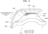
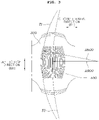
- the void bush for a vehicle suspension includes: an inner pipe 100 having a hole 110 passing from a first end thereof to a second end thereof, an outer pipe 200 positioned outside the inner pipe 100, and a rubber bush 300 filled in a space between the inner pipe 100 and the outer pipe 200 and having a void 310.
- the rubber bush 300 has an inside stopper 320 and an outside stopper 330, which are arranged to face each other so that the void 310 is positioned between the inside stopper 320 and the outside stopper 330.
- a front surface of the inside stopper 320 has a portion formed with inside bumps 400 and a front surface of the outside stopper 330 has a portion formed with outside bumps 500.
- the inside bumps 400 and the outside bumps 500 are arranged to face each other and to cross each other at right angles.
- the inside bumps 400 extend in a left to right direction (arrow M1), which is a penetration direction of the inner pipe 100, include a plurality of inside bumps 400 arranged in a circumferential direction (arrow R1).
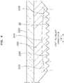
- the inside bumps 400 have curvatures T1, T2, etc. as the inside bump goes from opposite ends thereof toward a center portion between the opposite ends (referring to FIG. 3 ).
- a curvature T1 of one of the inside bumps 400 located in the outmost side of the inside bumps 400 in the circumferential direction is the smallest curvature (curvature of R600 or more).
- a curvature T2 of one of the inside bumps 400 located in the center of the inside bumps 400 in the circumferential direction is the greatest curvature (curvature of R900 or more).
- the outside bumps 500 extend in the circumferential direction (arrow R1), and include a plurality of the outside bumps 500 arranged in the left to right direction (arrow M1).
- the outside bumps 500 have curvatures S1, etc., which are curved as an outside bump goes from opposite ends of the circumferential direction (arrow R1) to a center portion between the opposite ends (referring to FIG. 4 ).
- Each of the outside bumps 500 has four inflection points X1, X2, X3, and X4 whose curvature is changed in the circumferential direction.
- the plurality of the outside bumps 500 is not arranged in parallel to each other by each having the four inflection points X1, X2, X3, and X4, which are arranged at different positions.
- the curvatures T1, T2, etc. of the inside bumps 400 and the curvatures S1, etc. of the outside bumps 500 are formed differently from each other.
- the outside bumps 500 are formed with curvatures of R1000 or more to have curvatures greater than the curvatures of the inside bumps 400.
- the inside bumps 400 and the outside bumps 500 are formed in a perpendicular direction to each other, so that the inside bumps 400 and the outside bumps 500 are in point-contact with each other during the behavior of a suspension.
- the inside bumps 400 and the outside bumps 500 and the inflection points X1, X2, X3, and X4 of each of the outside bumps 500 are not formed in parallel to each other and the outside bumps 500 are not formed in parallel to each other.
- the contact area between the inside bumps 400 and the outside bumps 500 may be greatly reduced and the contact abrasion positions between the inside bumps 400 and the outside bumps 500 may be diversified, so that local abrasion of the void bush may be prevented, and through the abrasion prevention, durability and lifespan of the void bush may be improved.
- the inside bumps 400 are divided into a real contact section 410 that actually contacts the outside bumps 500 and a non-contact section 420 that does not contact the outside bumps 500.
- the outside bumps 500 are divided into a real contact section 510 that actually contacts the inside bumps 400 and a non-contact section 520 that does not contact the inside bumps 400.
- the real contact section 410 of the inside bumps 400 and the real contact section 510 of the outside bumps 500 are brought into contact with each other.
- a bump height H1 of the real contact section 410 of the inside bumps 400 and a bump height H1 of the real contact section 510 of the outside bumps 500 are formed to have the same size.
- a bump height of the non-contact section 420 of the inside bumps 400 and a bump height of the non-contact section 520 of the outside bumps 500 may be formed to have the same size or different sizes.
- the real contact section 410 of the inside bumps 400 and the real contact section 510 of the outside bumps 500 are formed to have the same size of the bump height H1
- the real contact section 410 of the inside bumps 400 and the real contact section 510 of the outside bumps 500 are brought into contact with each other by the behavior of the suspension, thereby inducing uniform surface pressure. Accordingly, local abrasion of the void bush may be prevented so that durability and lifespan of the void bush may be improved.
- a curvature V1 of a base portion formed by connecting lowest points of real contact section-side inside bumps to each other is less than or equal to a curvature W1 of a highest portion formed by connecting highest points of the real contact section-side inside bumps.
- a curvature V2 of a base portion formed by connecting lowest points of non-contact section-side inside bumps to each other is equal to or greater than a curvature W2 of a highest portion formed by connecting highest points of the non-contact section-side inside bumps to each other.
- the base portion curvature V1 of the real contact section 410 and the base portion curvature V2 of the non-contact section 420 are connected to each other through inflection points X5 and X6 through which the curvatures are changed.
- a curvature V3 of a base portion formed by connecting lowest points of real contact section-side outside bumps to each other is less than or equal to a curvature W3 of a highest portion formed by connecting highest points of the real contact section-side outside bumps to each other.
- a curvature V4 of base portion formed by connecting lowest points of non-contact section-side outside bumps to each other is equal to or greater than a curvature W4 of a highest portion formed by connecting heist points of the non-contact section-side outside bumps to each other.
- the base portion curvature V3 of the real contact section 510 and the base portion curvature V4 of the non-contact section 520 are connected to each other through inflection points X7 and X8 through which the curvatures are changed.
- the change of the base portion curvatures V1 and V2 in the real contact section 410 and the non-contact section 420 of the inside bumps 400, the change of the base portion curvatures V3 and V4 in the real contact section 510 and the non-contact section 520 of the outside bumps 500, and the inflection points X5, X6, X7, and X8 are applied in the void bush, so that the volume of the rubber bush 300 may be greatly reduced compared to the conventional bush.
- the contraction space may be increased during low temperature contraction, and as a result, a gap of the void 310 between the inside stopper 320 and the outside stopper 330 may be greatly reduced under the low temperature condition where joint is well generated. Accordingly, initial contact timing and contact area due to increase of the gap may be reduced under the same friction load condition, and thus durability and lifespan of the void bush may be improved.
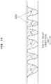
- the plurality of the inside bumps 400 is configured such that inside bumps continuously arranged and neighboring each other are formed to have different sectional areas.
- the inside bumps 400 are formed to have sectional areas a1, a2, a3, etc. that are continuously connected to each other, and one of the inside bumps 400 is formed to have a different sectional area from an inside bump adjacent thereto. In other words, a sectional area of a3 and adjacent sectional areas of a2 and a4 are formed differently from each other.
- outside bumps continuously arranged and neighboring each other are formed to have different sectional areas.
- the outside bumps 500 are formed to have sectional areas b1, b2, b3, etc. that are continuously connected to each other, and one of the outside bumps 500 is formed to have a different sectional area from an outside bump adjacent thereto. In other words, a sectional area of b3 and adjacent section areas of b2 and b4 are formed differently from each other.
- the inside bumps 400 and the outside bumps 500 that are brought into contact with each other during the behavior of the suspension have a configuration in which bumps having different sectional areas are in contact with each other.
- the contact area between the inside bumps 400 and the outside bumps 500 may be greatly reduced, and the contact abrasion positions between the inside bumps 400 and the outside bumps 500 are diversified, so that local abrasion of the void bush may be prevented, and thus, durability and lifespan thereof may be improved.
- the inside bumps 400 and the outside bumps 500 may be formed to have sectional areas of various sizes
- both the highest protrusion of each of the inside bumps 400 and the highest protrusion of each of the outside bumps 500 are formed in round shapes R3 with predetermined curvatures without flat surfaces. Therefore, the contact area between the inside bumps 400 and the outside bumps 500 may be greatly reduced, so that local abrasion of the void bush may be prevented and thus durability and lifespan of the void bush may be improved.
- the inside bumps 400 and the outside bumps 500 are configured to be perpendicular to each other, the inside bumps 400 and the outside bumps 500 are in point-contact with each other during the behavior of the suspension.
- the inside bumps 400 are not formed in parallel to each other, and the outside bumps 500 are not formed in parallel to each other.
- the contact area between the inside bumps 400 and the outside bumps 500 may be greatly reduced, and the contact abrasion positions between the inside bumps 400 and the outside bumps 500 may be diversified. Accordingly, local abrasion of the void bush may be prevented and thus durability and lifespan of the void bush may be improved.
- the respective bumps have the same height H1 as each other.
- uniform surface pressure may be induced, so that local abrasion of the void bush may be prevented and thus durability and lifespan of the void bush may be improved.
- the change of the base portion curvatures V1 and V2 in the real contact section 410 and the non-contact section 420 of the inside bumps 400, the change of the base portion curvatures V3 and V4 in the real contact section 510 and the non-contact section 520 of the outside bumps 500, and the inflection points X5, X6, X7, and X8 are applied to the present disclosure, so that the volume of the rubber bush 300 may be greatly reduced compared to the conventional bush.
- the contraction space may be increased during low temperature contraction, and as a result, a gap of the void 310 between the inside stopper 320 and the outside stopper 330 may be greatly reduced under the low temperature condition where joint is well generated. Accordingly, initial contact timing and contact area due to increase of the gap may be reduced under the same friction load condition, and thus durability and lifespan of the void bush may be improved.
- the inside bumps 400 and the outside bumps 500 that are brought into contact with each other during the behavior of the suspension are configured such that bumps having different sectional areas are brought into contact with each other on the basis of a first reference line L1 and a second reference line L2. Accordingly, the contact area between the inside bumps 400 and the outside bumps 500 may be greatly reduced, and the contact abrasion positions between the inside bumps 400 and the outside bumps 500 may be diversified, so that local abrasion of the void bush may be prevented and thus durability and lifespan of the void bush may be improved.
- Both the highest protrusion of each of the inside bumps 400 and the highest protrusion of each of the outside bumps 500 are formed in round shapes R3 with predetermined curvatures without flat surfaces. Therefore, the contact area between the inside bumps 400 and the outside bumps 500 may be greatly reduced, so that local abrasion of the void bush may be prevented and thus durability and lifespan of the void bush may be improved.
Landscapes
- Engineering & Computer Science (AREA)
- Mechanical Engineering (AREA)
- General Engineering & Computer Science (AREA)
- Springs (AREA)
- Vehicle Body Suspensions (AREA)
Claims (14)
- Hohlraumbuchse für eine Fahrzeugaufhängung, wobei die Hohlraumbuchse aufweist:eine Gummibuchse (300), die zwischen ein Innenrohr (100) und ein Außenrohr (200) gefüllt ist, wobei die Gummibuchse einen Hohlraum (310) aufweist, undeinen inneren Anschlag (320) und einen äußeren Anschlag (330), die angeordnet sind, um einander zugewandt zu sein, wobei der Hohlraum zwischen dem inneren Anschlag und dem äußeren Anschlag angeordnet ist,wobei:der innere Anschlag einen Innenerhebungsabschnitt aufweist und der äußere Anschlag einen Außenerhebungsabschnitt aufweist,der Innenerhebungsabschnitt und der Außenerhebungsabschnitt konfiguriert sind, um einander zu kreuzen,der Innenerhebungsabschnitt mit einer Mehrzahl von Innenerhebungen (400) bereitgestellt ist,der Außenerhebungsabschnitt mit einer Mehrzahl von Außenerhebungen (500) bereitgestellt ist, dadurch gekennzeichnet, dass unter der Mehrzahl von Innenerhebungen eine Krümmung (T1) einer Innenerhebung, die sich in einer Umfangsrichtung des Innenrohrs in einer Mitte der Mehrzahl von Innenerhebungen befindet, größer als eine Krümmung (T2) einer Innenerhebung ist, die sich in der Umfangsrichtung in einer äußersten Seite der Mehrzahl von Innenerhebungen befindet.
- Hohlraumbuchse gemäß Anspruch 1, wobei jede Außenerhebung der Mehrzahl von Außenerhebungen eine Mehrzahl von Beugungspunkten hat, deren Krümmungen sich in der Umfangsrichtung ändern.
- Hohlraumbuchse gemäß Anspruch 1 oder 2, wobei die Mehrzahl von Innenerhebungen und die Mehrzahl von Außenerhebungen unterschiedliche Krümmungen haben.
- Hohlraumbuchse gemäß irgendeinem der Ansprüche 1 bis 3, wobei die Mehrzahl von Innenerhebungen und die Mehrzahl von Außenerhebungen angeordnet sind, um einander in rechten Winkeln zu kreuzen.
- Hohlraumbuchse gemäß irgendeinem der Ansprüche 1 bis 4, wobei Innenerhebungen der Mehrzahl von Innenerhebungen nicht parallel zueinander angeordnet sind, indem sie jeweilige Krümmungen haben, die konfiguriert sind, um von einer in Umfangsrichtung Äußerste-Seite-Erhebung in Richtung zu einer in Umfangsrichtung Mittlere-Seite-Erhebung aus der Mehrzahl von Innenerhebungen allmählich größer zu werden.
- Hohlraumbuchse gemäß Anspruch 2, wobei jede Außenerhebung der Mehrzahl von Außenerhebungen vier Beugungspunkte hat, und
Außenerhebungen der Mehrzahl der Außenerhebungen nicht parallel zueinander angeordnet sind, indem jede die vier Beugungspunkte hat, die an unterschiedlichen Positionen angeordnet sind. - Hohlraumbuchse gemäß irgendeinem der Ansprüche 1 bis 6, wobei Innenerhebungen der Mehrzahl von Innenerhebungen in einen Echter-Kontakt-Abschnitt, der Außenerhebungen der Mehrzahl von Außenerhebungen tatsächlich kontaktiert, und einen Nicht-Kontakt-Abschnitt, der die Außenerhebungen nicht kontaktiert, unterteilt sind,die Außenerhebungen in einen Echter-Kontakt-Abschnitt, der die Innenerhebungen tatsächlich kontaktiert, und einen Nicht-Kontakt-Abschnitt, der die Innenerhebungen nicht kontaktiert, unterteilt sind, undEchter-Kontakt-Abschnitt-Seite-Innenerhebungen von den Innenerhebungen und Echter-Kontakt-Abschnitt-Seite-Außenerhebungen von den Außenerhebungen jeweils die gleiche Höhe haben.
- Hohlraumbuchse gemäß irgendeinem der Ansprüche 1 bis 6, wobei Innenerhebungen der Mehrzahl von Innenerhebungen in einen Echter-Kontakt-Abschnitt, der Außenerhebungen der Mehrzahl von Außenerhebungen tatsächlich kontaktiert, und einen Nicht-Kontakt-Abschnitt, der die Außenerhebungen nicht kontaktiert, unterteilt sind,in dem Echter-Kontakt-Abschnitt der Innenerhebungen eine Krümmung eines Basisabschnitts, der durch Verbinden von niedrigsten Punkten von Echter-Kontakt-Abschnitt-Seite-Innenerhebungen miteinander gebildet wird, kleiner oder gleich einer Krümmung eines höchsten Abschnitts ist, der durch Verbinden von höchsten Punkten der Echter-Kontakt-Abschnitt-Seite-Innenerhebungen miteinander gebildet wird,in dem Nicht-Kontakt-Abschnitt der Innenerhebungen eine Krümmung eines Basisabschnitts, der durch Verbinden von niedrigsten Punkten von Nicht-Kontakt-Abschnitt-Seite-Innenerhebungen miteinander gebildet wird, größer oder gleich einer Krümmung eines höchsten Abschnitts ist, der durch Verbinden von höchsten Punkten der Nicht-Kontakt-Abschnitt-Seite-Innenerhebungen miteinander gebildet wird, undin den Innenerhebungen die Basisabschnittkrümmung des Echter-Kontakt-Abschnitts und die Basisabschnittkrümmung des Nicht-Kontakt-Abschnitts durch Beugungspunkte, durch die die Krümmungen geändert werden, miteinander verbunden sind.
- Hohlraumbuchse gemäß irgendeinem der Ansprüche 1 bis 6, wobei Außenerhebungen der Mehrzahl von Außenerhebungen in einen Echter-Kontakt-Abschnitt, der Innenerhebungen der Mehrzahl von Innenerhebungen tatsächlich kontaktiert, und einen Nicht-Kontakt-Abschnitt, der die Innenerhebungen nicht kontaktiert, unterteilt sind,in dem Echter-Kontakt-Abschnitt der Außenerhebungen eine Krümmung eines Basisabschnitts, der durch Verbinden von niedrigsten Punkten von Echter-Kontakt-Abschnitt-Seite-Außenerhebungen miteinander gebildet wird, kleiner oder gleich einer Krümmung eines höchsten Abschnitts ist, der durch Verbinden von höchsten Punkten der Echter-Kontakt-Abschnitt-Seite-Außenerhebungen miteinander gebildet wird,in dem Nicht-Kontakt-Abschnitt der Außenerhebungen eine Krümmung eines Basisabschnitts, der durch Verbinden von niedrigsten Punkten von Nicht-Kontakt-Abschnitt-Seite-Außenerhebungen miteinander gebildet wird, größer oder gleich einer Krümmung eines höchsten Abschnitts ist, der durch Verbinden von höchsten Punkten der Nicht-Kontakt-Abschnitt-Seite-Außenerhebungen miteinander gebildet wird, undin den Außenerhebungen die Basisabschnittkrümmung des Echter-Kontakt-Abschnitts und die Basisabschnittkrümmung des Nicht-Kontakt-Abschnitts durch Beugungspunkte, durch die die Krümmungen geändert werden, miteinander verbunden sind.
- Hohlraumbuchse gemäß irgendeinem der Ansprüche 1 bis 9, wobei Innenerhebungen der Mehrzahl von Innenerhebungen derart konfiguriert sind, dass die kontinuierlich angeordneten und zueinander benachbarten Innenerhebungen unterschiedliche Querschnittsflächen haben, und
Außenerhebungen der Mehrzahl von Außenerhebungen derart konfiguriert sind, dass die kontinuierlich angeordneten und zueinander benachbarten Außenerhebungen unterschiedliche Querschnittsflächen haben. - Hohlraumbuchse gemäß irgendeinem der Ansprüche 1 bis 10, wobei ein höchster Vorsprung jeder Innenerhebung der Mehrzahl von Innenerhebungen und ein höchster Vorsprung jeder Außenerhebung der Mehrzahl von Außenerhebungen jeweils runde Formen mit vorbestimmten Krümmungen haben.
- Hohlraumbuchse gemäß irgendeinem der Ansprüche 1 bis 11, wobei sich jede Innenerhebung der Mehrzahl von Innenerhebungen in einer Richtung von links nach rechts erstreckt, die eine Durchtrittsrichtung des Innenrohrs ist, und die Mehrzahl von Innenerhebungen in der Umfangsrichtung angeordnet ist.
- Hohlraumbuchse gemäß irgendeinem der Ansprüche 1 bis 12, wobei sich jede Außenerhebung der Mehrzahl von Außenerhebungen in der Umfangsrichtung erstreckt und die Mehrzahl von Außenerhebungen in einer Richtung von links nach rechts angeordnet ist, die eine Durchtrittsrichtung des Innenrohrs ist.
- Hohlraumbuchse gemäß irgendeinem der Ansprüche 1 bis 13, wobei jede Außenerhebung der Mehrzahl von Außenerhebungen eine Krümmung hat, die größer als eine Krümmung jeder Innenerhebung der Mehrzahl von Innenerhebungen ist.
Applications Claiming Priority (1)
| Application Number | Priority Date | Filing Date | Title |
|---|---|---|---|
| KR1020190142210A KR102767246B1 (ko) | 2019-11-08 | 2019-11-08 | 차량 서스펜션용 보이드 부시 |
Publications (2)
| Publication Number | Publication Date |
|---|---|
| EP3822508A1 EP3822508A1 (de) | 2021-05-19 |
| EP3822508B1 true EP3822508B1 (de) | 2022-06-29 |
Family
ID=73172516
Family Applications (1)
| Application Number | Title | Priority Date | Filing Date |
|---|---|---|---|
| EP20206144.6A Active EP3822508B1 (de) | 2019-11-08 | 2020-11-06 | Hohlraumbuchse für eine fahrzeugaufhängung |
Country Status (4)
| Country | Link |
|---|---|
| US (1) | US11453262B2 (de) |
| EP (1) | EP3822508B1 (de) |
| KR (1) | KR102767246B1 (de) |
| CN (1) | CN112776549B (de) |
Families Citing this family (1)
| Publication number | Priority date | Publication date | Assignee | Title |
|---|---|---|---|---|
| KR20230024601A (ko) * | 2021-08-12 | 2023-02-21 | 현대자동차주식회사 | Ctba 부시 |
Family Cites Families (25)
| Publication number | Priority date | Publication date | Assignee | Title |
|---|---|---|---|---|
| GB1090566A (en) * | 1965-05-03 | 1967-11-08 | Aeon Products London Ltd | Improvements in and relating to springs |
| DE1475137B2 (de) * | 1965-05-15 | 1971-02-25 | Rix, Johannes Dipl Ing , 3500 Kassel | Hohlfelder insbesondere zum auffangen von stoessen bei fahrzeugen |
| US4166875A (en) * | 1977-10-07 | 1979-09-04 | Bussey Harry Jr | Free-flowing packaging material |
| US4169179A (en) * | 1977-10-07 | 1979-09-25 | Bussey Harry Jun | Spring-like loose fill packaging material |
| JPS6439941U (de) * | 1987-09-03 | 1989-03-09 | ||
| US4877224A (en) * | 1988-08-31 | 1989-10-31 | Watts James L | Corrugated energy absorber |
| JPH0968247A (ja) | 1995-08-30 | 1997-03-11 | Toyota Motor Corp | ブッシュ |
| JP3693834B2 (ja) * | 1998-12-28 | 2005-09-14 | 株式会社ブリヂストン | 防振装置 |
| US20050202211A1 (en) * | 2002-12-18 | 2005-09-15 | Goodrich Corporation | Engineered flexure component |
| JP4566095B2 (ja) * | 2005-08-31 | 2010-10-20 | 東海ゴム工業株式会社 | ストラットアームブッシュおよびそれを用いたダブルジョイント式サスペンション |
| KR20070032134A (ko) | 2005-09-16 | 2007-03-21 | 현대자동차주식회사 | 전륜 현가 장치용 텐션 링크 부시 |
| JP4505748B2 (ja) * | 2005-12-16 | 2010-07-21 | 東海ゴム工業株式会社 | 防振ゴム装置 |
| JP4666692B2 (ja) | 2006-03-17 | 2011-04-06 | 東海ゴム工業株式会社 | 防振ブッシュおよびその製造方法 |
| US20100044939A1 (en) * | 2008-08-20 | 2010-02-25 | Myron Stuart Hurwitz | Minimal to non-bulging urethane compression springs |
| KR20100035876A (ko) * | 2008-09-29 | 2010-04-07 | 현대위아 주식회사 | 자동차용 마운팅 부시 |
| JP5401701B2 (ja) | 2009-06-29 | 2014-01-29 | 東海ゴム工業株式会社 | 筒状金具の製造方法及び該筒状金具を用いた防振ゴムブッシュの製造方法 |
| KR20110023274A (ko) * | 2009-08-31 | 2011-03-08 | 현대모비스 주식회사 | 차량의 스테빌라이저바 장착장치 |
| CA2746210C (en) * | 2010-07-14 | 2017-07-11 | Andre Senecal | Device for preventing overdrawing of winch hook |
| CA2732392A1 (en) * | 2011-02-22 | 2012-08-22 | H & L Tool & Die Ltd. | Method and apparatus for producing a stabilizer bar assembly |
| US8628101B2 (en) * | 2011-05-16 | 2014-01-14 | Nissan Motor Co., Ltd. | Suspension structure, bush structure and suspension characteristic adjusting method |
| KR20130074896A (ko) * | 2011-12-27 | 2013-07-05 | 주식회사 파브코 | 부시 |
| JP2014145410A (ja) * | 2013-01-29 | 2014-08-14 | Tokai Rubber Ind Ltd | サスペンションブッシュ |
| KR101791555B1 (ko) * | 2016-06-29 | 2017-10-31 | 대원강업주식회사 | 저마찰형 마운팅 부시 |
| US10854184B2 (en) * | 2018-12-04 | 2020-12-01 | Ford Global Technologies, Llc | Friction damped insert for highly stressed engineering components |
| JP7042227B2 (ja) * | 2019-02-15 | 2022-03-25 | 本田技研工業株式会社 | 可変剛性ブッシュ |
-
2019
- 2019-11-08 KR KR1020190142210A patent/KR102767246B1/ko active Active
-
2020
- 2020-11-04 US US17/088,926 patent/US11453262B2/en active Active
- 2020-11-06 CN CN202011228700.8A patent/CN112776549B/zh active Active
- 2020-11-06 EP EP20206144.6A patent/EP3822508B1/de active Active
Also Published As
| Publication number | Publication date |
|---|---|
| EP3822508A1 (de) | 2021-05-19 |
| KR102767246B1 (ko) | 2025-02-12 |
| CN112776549A (zh) | 2021-05-11 |
| CN112776549B (zh) | 2026-02-06 |
| US11453262B2 (en) | 2022-09-27 |
| KR20210056464A (ko) | 2021-05-20 |
| US20210138859A1 (en) | 2021-05-13 |
Similar Documents
| Publication | Publication Date | Title |
|---|---|---|
| US8210508B2 (en) | Bump stopper for suspension system | |
| US4667943A (en) | Resilient bushing | |
| US9694638B2 (en) | Spring rubber seat and strut-type suspension | |
| KR101839537B1 (ko) | 비공기입 타이어 | |
| US9579946B2 (en) | Trailing arm bush for coupled torsion beam axle | |
| EP3822508B1 (de) | Hohlraumbuchse für eine fahrzeugaufhängung | |
| US12472790B2 (en) | Vehicle strut insulator | |
| JP3978177B2 (ja) | ロアアームアセンブリー | |
| JP2010048293A (ja) | 防振ブッシュ | |
| JP3937042B2 (ja) | ストラットマウント | |
| US20210148429A1 (en) | Subframe Mounting Bush Structure | |
| CN209852011U (zh) | 一种新型下弹簧垫结构 | |
| JPH0874932A (ja) | ブッシュ型防振装置 | |
| KR102394155B1 (ko) | 나선형 홈이 정의된 파이프 및 이를 포함하는 부싱 | |
| KR20070032134A (ko) | 전륜 현가 장치용 텐션 링크 부시 | |
| KR101927729B1 (ko) | 차량용 머플러 행거 | |
| KR200149903Y1 (ko) | 인터파이프형 러버부시 | |
| JP2008240987A (ja) | 防振装置 | |
| KR20210066303A (ko) | 차량용 스테빌라이저 바 | |
| JP2804301B2 (ja) | 異方性空気ばね | |
| KR101927739B1 (ko) | 차량용 머플러 행거 | |
| JP2024178786A (ja) | 車両懸架装置用スプリングシート | |
| JPH11351298A (ja) | 防振装置用ストッパ | |
| JPH11182596A (ja) | 車両サスペンション用緩衝装置 | |
| KR100428132B1 (ko) | 현가장치의 스트럿어셈블리 |
Legal Events
| Date | Code | Title | Description |
|---|---|---|---|
| PUAI | Public reference made under article 153(3) epc to a published international application that has entered the european phase |
Free format text: ORIGINAL CODE: 0009012 |
|
| STAA | Information on the status of an ep patent application or granted ep patent |
Free format text: STATUS: THE APPLICATION HAS BEEN PUBLISHED |
|
| AK | Designated contracting states |
Kind code of ref document: A1 Designated state(s): AL AT BE BG CH CY CZ DE DK EE ES FI FR GB GR HR HU IE IS IT LI LT LU LV MC MK MT NL NO PL PT RO RS SE SI SK SM TR |
|
| STAA | Information on the status of an ep patent application or granted ep patent |
Free format text: STATUS: REQUEST FOR EXAMINATION WAS MADE |
|
| 17P | Request for examination filed |
Effective date: 20210518 |
|
| RBV | Designated contracting states (corrected) |
Designated state(s): AL AT BE BG CH CY CZ DE DK EE ES FI FR GB GR HR HU IE IS IT LI LT LU LV MC MK MT NL NO PL PT RO RS SE SI SK SM TR |
|
| RAP3 | Party data changed (applicant data changed or rights of an application transferred) |
Owner name: HYUNDAI MOTOR COMPANY Owner name: KIA CORPORATION |
|
| RIC1 | Information provided on ipc code assigned before grant |
Ipc: F16F 1/38 20060101AFI20210928BHEP |
|
| GRAP | Despatch of communication of intention to grant a patent |
Free format text: ORIGINAL CODE: EPIDOSNIGR1 |
|
| STAA | Information on the status of an ep patent application or granted ep patent |
Free format text: STATUS: GRANT OF PATENT IS INTENDED |
|
| INTG | Intention to grant announced |
Effective date: 20220117 |
|
| GRAS | Grant fee paid |
Free format text: ORIGINAL CODE: EPIDOSNIGR3 |
|
| GRAA | (expected) grant |
Free format text: ORIGINAL CODE: 0009210 |
|
| STAA | Information on the status of an ep patent application or granted ep patent |
Free format text: STATUS: THE PATENT HAS BEEN GRANTED |
|
| AK | Designated contracting states |
Kind code of ref document: B1 Designated state(s): AL AT BE BG CH CY CZ DE DK EE ES FI FR GB GR HR HU IE IS IT LI LT LU LV MC MK MT NL NO PL PT RO RS SE SI SK SM TR |
|
| REG | Reference to a national code |
Ref country code: CH Ref legal event code: EP |
|
| REG | Reference to a national code |
Ref country code: AT Ref legal event code: REF Ref document number: 1501536 Country of ref document: AT Kind code of ref document: T Effective date: 20220715 |
|
| REG | Reference to a national code |
Ref country code: IE Ref legal event code: FG4D |
|
| REG | Reference to a national code |
Ref country code: DE Ref legal event code: R096 Ref document number: 602020003770 Country of ref document: DE |
|
| REG | Reference to a national code |
Ref country code: LT Ref legal event code: MG9D |
|
| PG25 | Lapsed in a contracting state [announced via postgrant information from national office to epo] |
Ref country code: SE Free format text: LAPSE BECAUSE OF FAILURE TO SUBMIT A TRANSLATION OF THE DESCRIPTION OR TO PAY THE FEE WITHIN THE PRESCRIBED TIME-LIMIT Effective date: 20220629 Ref country code: NO Free format text: LAPSE BECAUSE OF FAILURE TO SUBMIT A TRANSLATION OF THE DESCRIPTION OR TO PAY THE FEE WITHIN THE PRESCRIBED TIME-LIMIT Effective date: 20220929 Ref country code: LT Free format text: LAPSE BECAUSE OF FAILURE TO SUBMIT A TRANSLATION OF THE DESCRIPTION OR TO PAY THE FEE WITHIN THE PRESCRIBED TIME-LIMIT Effective date: 20220629 Ref country code: HR Free format text: LAPSE BECAUSE OF FAILURE TO SUBMIT A TRANSLATION OF THE DESCRIPTION OR TO PAY THE FEE WITHIN THE PRESCRIBED TIME-LIMIT Effective date: 20220629 Ref country code: GR Free format text: LAPSE BECAUSE OF FAILURE TO SUBMIT A TRANSLATION OF THE DESCRIPTION OR TO PAY THE FEE WITHIN THE PRESCRIBED TIME-LIMIT Effective date: 20220930 Ref country code: FI Free format text: LAPSE BECAUSE OF FAILURE TO SUBMIT A TRANSLATION OF THE DESCRIPTION OR TO PAY THE FEE WITHIN THE PRESCRIBED TIME-LIMIT Effective date: 20220629 Ref country code: BG Free format text: LAPSE BECAUSE OF FAILURE TO SUBMIT A TRANSLATION OF THE DESCRIPTION OR TO PAY THE FEE WITHIN THE PRESCRIBED TIME-LIMIT Effective date: 20220929 |
|
| REG | Reference to a national code |
Ref country code: NL Ref legal event code: MP Effective date: 20220629 |
|
| REG | Reference to a national code |
Ref country code: AT Ref legal event code: MK05 Ref document number: 1501536 Country of ref document: AT Kind code of ref document: T Effective date: 20220629 |
|
| PG25 | Lapsed in a contracting state [announced via postgrant information from national office to epo] |
Ref country code: RS Free format text: LAPSE BECAUSE OF FAILURE TO SUBMIT A TRANSLATION OF THE DESCRIPTION OR TO PAY THE FEE WITHIN THE PRESCRIBED TIME-LIMIT Effective date: 20220629 Ref country code: LV Free format text: LAPSE BECAUSE OF FAILURE TO SUBMIT A TRANSLATION OF THE DESCRIPTION OR TO PAY THE FEE WITHIN THE PRESCRIBED TIME-LIMIT Effective date: 20220629 |
|
| PG25 | Lapsed in a contracting state [announced via postgrant information from national office to epo] |
Ref country code: NL Free format text: LAPSE BECAUSE OF FAILURE TO SUBMIT A TRANSLATION OF THE DESCRIPTION OR TO PAY THE FEE WITHIN THE PRESCRIBED TIME-LIMIT Effective date: 20220629 |
|
| PG25 | Lapsed in a contracting state [announced via postgrant information from national office to epo] |
Ref country code: SM Free format text: LAPSE BECAUSE OF FAILURE TO SUBMIT A TRANSLATION OF THE DESCRIPTION OR TO PAY THE FEE WITHIN THE PRESCRIBED TIME-LIMIT Effective date: 20220629 Ref country code: SK Free format text: LAPSE BECAUSE OF FAILURE TO SUBMIT A TRANSLATION OF THE DESCRIPTION OR TO PAY THE FEE WITHIN THE PRESCRIBED TIME-LIMIT Effective date: 20220629 Ref country code: RO Free format text: LAPSE BECAUSE OF FAILURE TO SUBMIT A TRANSLATION OF THE DESCRIPTION OR TO PAY THE FEE WITHIN THE PRESCRIBED TIME-LIMIT Effective date: 20220629 Ref country code: PT Free format text: LAPSE BECAUSE OF FAILURE TO SUBMIT A TRANSLATION OF THE DESCRIPTION OR TO PAY THE FEE WITHIN THE PRESCRIBED TIME-LIMIT Effective date: 20221031 Ref country code: ES Free format text: LAPSE BECAUSE OF FAILURE TO SUBMIT A TRANSLATION OF THE DESCRIPTION OR TO PAY THE FEE WITHIN THE PRESCRIBED TIME-LIMIT Effective date: 20220629 Ref country code: EE Free format text: LAPSE BECAUSE OF FAILURE TO SUBMIT A TRANSLATION OF THE DESCRIPTION OR TO PAY THE FEE WITHIN THE PRESCRIBED TIME-LIMIT Effective date: 20220629 Ref country code: AT Free format text: LAPSE BECAUSE OF FAILURE TO SUBMIT A TRANSLATION OF THE DESCRIPTION OR TO PAY THE FEE WITHIN THE PRESCRIBED TIME-LIMIT Effective date: 20220629 |
|
| PG25 | Lapsed in a contracting state [announced via postgrant information from national office to epo] |
Ref country code: PL Free format text: LAPSE BECAUSE OF FAILURE TO SUBMIT A TRANSLATION OF THE DESCRIPTION OR TO PAY THE FEE WITHIN THE PRESCRIBED TIME-LIMIT Effective date: 20220629 Ref country code: IS Free format text: LAPSE BECAUSE OF FAILURE TO SUBMIT A TRANSLATION OF THE DESCRIPTION OR TO PAY THE FEE WITHIN THE PRESCRIBED TIME-LIMIT Effective date: 20221029 |
|
| REG | Reference to a national code |
Ref country code: DE Ref legal event code: R097 Ref document number: 602020003770 Country of ref document: DE |
|
| PG25 | Lapsed in a contracting state [announced via postgrant information from national office to epo] |
Ref country code: AL Free format text: LAPSE BECAUSE OF FAILURE TO SUBMIT A TRANSLATION OF THE DESCRIPTION OR TO PAY THE FEE WITHIN THE PRESCRIBED TIME-LIMIT Effective date: 20220629 |
|
| PG25 | Lapsed in a contracting state [announced via postgrant information from national office to epo] |
Ref country code: DK Free format text: LAPSE BECAUSE OF FAILURE TO SUBMIT A TRANSLATION OF THE DESCRIPTION OR TO PAY THE FEE WITHIN THE PRESCRIBED TIME-LIMIT Effective date: 20220629 Ref country code: CZ Free format text: LAPSE BECAUSE OF FAILURE TO SUBMIT A TRANSLATION OF THE DESCRIPTION OR TO PAY THE FEE WITHIN THE PRESCRIBED TIME-LIMIT Effective date: 20220629 |
|
| PLBE | No opposition filed within time limit |
Free format text: ORIGINAL CODE: 0009261 |
|
| STAA | Information on the status of an ep patent application or granted ep patent |
Free format text: STATUS: NO OPPOSITION FILED WITHIN TIME LIMIT |
|
| 26N | No opposition filed |
Effective date: 20230330 |
|
| P01 | Opt-out of the competence of the unified patent court (upc) registered |
Effective date: 20230504 |
|
| PG25 | Lapsed in a contracting state [announced via postgrant information from national office to epo] |
Ref country code: MC Free format text: LAPSE BECAUSE OF FAILURE TO SUBMIT A TRANSLATION OF THE DESCRIPTION OR TO PAY THE FEE WITHIN THE PRESCRIBED TIME-LIMIT Effective date: 20220629 |
|
| REG | Reference to a national code |
Ref country code: BE Ref legal event code: MM Effective date: 20221130 |
|
| PG25 | Lapsed in a contracting state [announced via postgrant information from national office to epo] |
Ref country code: SI Free format text: LAPSE BECAUSE OF FAILURE TO SUBMIT A TRANSLATION OF THE DESCRIPTION OR TO PAY THE FEE WITHIN THE PRESCRIBED TIME-LIMIT Effective date: 20220629 Ref country code: LU Free format text: LAPSE BECAUSE OF NON-PAYMENT OF DUE FEES Effective date: 20221106 |
|
| PG25 | Lapsed in a contracting state [announced via postgrant information from national office to epo] |
Ref country code: IE Free format text: LAPSE BECAUSE OF NON-PAYMENT OF DUE FEES Effective date: 20221106 |
|
| PG25 | Lapsed in a contracting state [announced via postgrant information from national office to epo] |
Ref country code: FR Free format text: LAPSE BECAUSE OF NON-PAYMENT OF DUE FEES Effective date: 20221130 Ref country code: BE Free format text: LAPSE BECAUSE OF NON-PAYMENT OF DUE FEES Effective date: 20221130 |
|
| PG25 | Lapsed in a contracting state [announced via postgrant information from national office to epo] |
Ref country code: IT Free format text: LAPSE BECAUSE OF FAILURE TO SUBMIT A TRANSLATION OF THE DESCRIPTION OR TO PAY THE FEE WITHIN THE PRESCRIBED TIME-LIMIT Effective date: 20220629 |
|
| PG25 | Lapsed in a contracting state [announced via postgrant information from national office to epo] |
Ref country code: CY Free format text: LAPSE BECAUSE OF FAILURE TO SUBMIT A TRANSLATION OF THE DESCRIPTION OR TO PAY THE FEE WITHIN THE PRESCRIBED TIME-LIMIT Effective date: 20220629 |
|
| PG25 | Lapsed in a contracting state [announced via postgrant information from national office to epo] |
Ref country code: MK Free format text: LAPSE BECAUSE OF FAILURE TO SUBMIT A TRANSLATION OF THE DESCRIPTION OR TO PAY THE FEE WITHIN THE PRESCRIBED TIME-LIMIT Effective date: 20220629 |
|
| PG25 | Lapsed in a contracting state [announced via postgrant information from national office to epo] |
Ref country code: TR Free format text: LAPSE BECAUSE OF FAILURE TO SUBMIT A TRANSLATION OF THE DESCRIPTION OR TO PAY THE FEE WITHIN THE PRESCRIBED TIME-LIMIT Effective date: 20220629 |
|
| REG | Reference to a national code |
Ref country code: CH Ref legal event code: PL |
|
| PG25 | Lapsed in a contracting state [announced via postgrant information from national office to epo] |
Ref country code: CH Free format text: LAPSE BECAUSE OF NON-PAYMENT OF DUE FEES Effective date: 20231130 |
|
| PG25 | Lapsed in a contracting state [announced via postgrant information from national office to epo] |
Ref country code: HU Free format text: LAPSE BECAUSE OF FAILURE TO SUBMIT A TRANSLATION OF THE DESCRIPTION OR TO PAY THE FEE WITHIN THE PRESCRIBED TIME-LIMIT; INVALID AB INITIO Effective date: 20201106 Ref country code: CH Free format text: LAPSE BECAUSE OF NON-PAYMENT OF DUE FEES Effective date: 20231130 |
|
| PG25 | Lapsed in a contracting state [announced via postgrant information from national office to epo] |
Ref country code: MT Free format text: LAPSE BECAUSE OF FAILURE TO SUBMIT A TRANSLATION OF THE DESCRIPTION OR TO PAY THE FEE WITHIN THE PRESCRIBED TIME-LIMIT Effective date: 20220629 |
|
| PG25 | Lapsed in a contracting state [announced via postgrant information from national office to epo] |
Ref country code: BG Free format text: LAPSE BECAUSE OF FAILURE TO SUBMIT A TRANSLATION OF THE DESCRIPTION OR TO PAY THE FEE WITHIN THE PRESCRIBED TIME-LIMIT Effective date: 20220629 |
|
| PG25 | Lapsed in a contracting state [announced via postgrant information from national office to epo] |
Ref country code: BG Free format text: LAPSE BECAUSE OF FAILURE TO SUBMIT A TRANSLATION OF THE DESCRIPTION OR TO PAY THE FEE WITHIN THE PRESCRIBED TIME-LIMIT Effective date: 20220629 |
|
| GBPC | Gb: european patent ceased through non-payment of renewal fee |
Effective date: 20241106 |
|
| PG25 | Lapsed in a contracting state [announced via postgrant information from national office to epo] |
Ref country code: GB Free format text: LAPSE BECAUSE OF NON-PAYMENT OF DUE FEES Effective date: 20241106 |
|
| PGFP | Annual fee paid to national office [announced via postgrant information from national office to epo] |
Ref country code: DE Payment date: 20251020 Year of fee payment: 6 |