EP3822485A1 - Kapazitätssteuerungsventil - Google Patents
Kapazitätssteuerungsventil Download PDFInfo
- Publication number
- EP3822485A1 EP3822485A1 EP19834984.7A EP19834984A EP3822485A1 EP 3822485 A1 EP3822485 A1 EP 3822485A1 EP 19834984 A EP19834984 A EP 19834984A EP 3822485 A1 EP3822485 A1 EP 3822485A1
- Authority
- EP
- European Patent Office
- Prior art keywords
- valve
- control
- differential
- port
- pressure
- Prior art date
- Legal status (The legal status is an assumption and is not a legal conclusion. Google has not performed a legal analysis and makes no representation as to the accuracy of the status listed.)
- Granted
Links
- 239000012530 fluid Substances 0.000 claims abstract description 52
- 238000004891 communication Methods 0.000 claims description 26
- 230000033228 biological regulation Effects 0.000 claims description 6
- 230000001105 regulatory effect Effects 0.000 claims description 2
- 230000002093 peripheral effect Effects 0.000 description 35
- 238000006073 displacement reaction Methods 0.000 description 33
- XEEYBQQBJWHFJM-UHFFFAOYSA-N Iron Chemical group [Fe] XEEYBQQBJWHFJM-UHFFFAOYSA-N 0.000 description 15
- 238000007599 discharging Methods 0.000 description 8
- 238000005192 partition Methods 0.000 description 8
- 238000004378 air conditioning Methods 0.000 description 7
- 239000003507 refrigerant Substances 0.000 description 7
- 230000007423 decrease Effects 0.000 description 6
- 230000004044 response Effects 0.000 description 6
- 230000001276 controlling effect Effects 0.000 description 5
- 238000001816 cooling Methods 0.000 description 4
- 238000000926 separation method Methods 0.000 description 4
- 230000008859 change Effects 0.000 description 3
- 230000006835 compression Effects 0.000 description 3
- 238000007906 compression Methods 0.000 description 3
- 238000003780 insertion Methods 0.000 description 3
- 230000037431 insertion Effects 0.000 description 3
- 230000007246 mechanism Effects 0.000 description 3
- 230000004043 responsiveness Effects 0.000 description 3
- 230000015572 biosynthetic process Effects 0.000 description 2
- 229910052742 iron Inorganic materials 0.000 description 2
- 229910000976 Electrical steel Inorganic materials 0.000 description 1
- 238000007792 addition Methods 0.000 description 1
- 230000003247 decreasing effect Effects 0.000 description 1
- 238000010586 diagram Methods 0.000 description 1
- 230000005284 excitation Effects 0.000 description 1
- 238000009434 installation Methods 0.000 description 1
- 239000000696 magnetic material Substances 0.000 description 1
- 239000000463 material Substances 0.000 description 1
- 239000007769 metal material Substances 0.000 description 1
- 238000000034 method Methods 0.000 description 1
- 238000012986 modification Methods 0.000 description 1
- 230000004048 modification Effects 0.000 description 1
- 238000005057 refrigeration Methods 0.000 description 1
- 239000011347 resin Substances 0.000 description 1
- 229920005989 resin Polymers 0.000 description 1
- 238000007789 sealing Methods 0.000 description 1
- 239000007787 solid Substances 0.000 description 1
Images


Classifications
-
- F—MECHANICAL ENGINEERING; LIGHTING; HEATING; WEAPONS; BLASTING
- F04—POSITIVE - DISPLACEMENT MACHINES FOR LIQUIDS; PUMPS FOR LIQUIDS OR ELASTIC FLUIDS
- F04B—POSITIVE-DISPLACEMENT MACHINES FOR LIQUIDS; PUMPS
- F04B27/00—Multi-cylinder pumps specially adapted for elastic fluids and characterised by number or arrangement of cylinders
- F04B27/08—Multi-cylinder pumps specially adapted for elastic fluids and characterised by number or arrangement of cylinders having cylinders coaxial with, or parallel or inclined to, main shaft axis
- F04B27/14—Control
- F04B27/16—Control of pumps with stationary cylinders
- F04B27/18—Control of pumps with stationary cylinders by varying the relative positions of a swash plate and a cylinder block
- F04B27/1804—Controlled by crankcase pressure
-
- F—MECHANICAL ENGINEERING; LIGHTING; HEATING; WEAPONS; BLASTING
- F04—POSITIVE - DISPLACEMENT MACHINES FOR LIQUIDS; PUMPS FOR LIQUIDS OR ELASTIC FLUIDS
- F04B—POSITIVE-DISPLACEMENT MACHINES FOR LIQUIDS; PUMPS
- F04B27/00—Multi-cylinder pumps specially adapted for elastic fluids and characterised by number or arrangement of cylinders
- F04B27/08—Multi-cylinder pumps specially adapted for elastic fluids and characterised by number or arrangement of cylinders having cylinders coaxial with, or parallel or inclined to, main shaft axis
- F04B27/10—Multi-cylinder pumps specially adapted for elastic fluids and characterised by number or arrangement of cylinders having cylinders coaxial with, or parallel or inclined to, main shaft axis having stationary cylinders
-
- F—MECHANICAL ENGINEERING; LIGHTING; HEATING; WEAPONS; BLASTING
- F04—POSITIVE - DISPLACEMENT MACHINES FOR LIQUIDS; PUMPS FOR LIQUIDS OR ELASTIC FLUIDS
- F04B—POSITIVE-DISPLACEMENT MACHINES FOR LIQUIDS; PUMPS
- F04B27/00—Multi-cylinder pumps specially adapted for elastic fluids and characterised by number or arrangement of cylinders
- F04B27/08—Multi-cylinder pumps specially adapted for elastic fluids and characterised by number or arrangement of cylinders having cylinders coaxial with, or parallel or inclined to, main shaft axis
- F04B27/14—Control
- F04B27/16—Control of pumps with stationary cylinders
- F04B27/18—Control of pumps with stationary cylinders by varying the relative positions of a swash plate and a cylinder block
-
- F—MECHANICAL ENGINEERING; LIGHTING; HEATING; WEAPONS; BLASTING
- F16—ENGINEERING ELEMENTS AND UNITS; GENERAL MEASURES FOR PRODUCING AND MAINTAINING EFFECTIVE FUNCTIONING OF MACHINES OR INSTALLATIONS; THERMAL INSULATION IN GENERAL
- F16K—VALVES; TAPS; COCKS; ACTUATING-FLOATS; DEVICES FOR VENTING OR AERATING
- F16K31/00—Actuating devices; Operating means; Releasing devices
- F16K31/02—Actuating devices; Operating means; Releasing devices electric; magnetic
- F16K31/06—Actuating devices; Operating means; Releasing devices electric; magnetic using a magnet, e.g. diaphragm valves, cutting off by means of a liquid
- F16K31/0603—Multiple-way valves
- F16K31/0606—Multiple-way valves fluid passing through the solenoid coil
-
- F—MECHANICAL ENGINEERING; LIGHTING; HEATING; WEAPONS; BLASTING
- F04—POSITIVE - DISPLACEMENT MACHINES FOR LIQUIDS; PUMPS FOR LIQUIDS OR ELASTIC FLUIDS
- F04B—POSITIVE-DISPLACEMENT MACHINES FOR LIQUIDS; PUMPS
- F04B27/00—Multi-cylinder pumps specially adapted for elastic fluids and characterised by number or arrangement of cylinders
- F04B27/08—Multi-cylinder pumps specially adapted for elastic fluids and characterised by number or arrangement of cylinders having cylinders coaxial with, or parallel or inclined to, main shaft axis
- F04B27/14—Control
- F04B27/16—Control of pumps with stationary cylinders
- F04B27/18—Control of pumps with stationary cylinders by varying the relative positions of a swash plate and a cylinder block
- F04B27/1804—Controlled by crankcase pressure
- F04B2027/1809—Controlled pressure
- F04B2027/1813—Crankcase pressure
-
- F—MECHANICAL ENGINEERING; LIGHTING; HEATING; WEAPONS; BLASTING
- F04—POSITIVE - DISPLACEMENT MACHINES FOR LIQUIDS; PUMPS FOR LIQUIDS OR ELASTIC FLUIDS
- F04B—POSITIVE-DISPLACEMENT MACHINES FOR LIQUIDS; PUMPS
- F04B27/00—Multi-cylinder pumps specially adapted for elastic fluids and characterised by number or arrangement of cylinders
- F04B27/08—Multi-cylinder pumps specially adapted for elastic fluids and characterised by number or arrangement of cylinders having cylinders coaxial with, or parallel or inclined to, main shaft axis
- F04B27/14—Control
- F04B27/16—Control of pumps with stationary cylinders
- F04B27/18—Control of pumps with stationary cylinders by varying the relative positions of a swash plate and a cylinder block
- F04B27/1804—Controlled by crankcase pressure
- F04B2027/1822—Valve-controlled fluid connection
- F04B2027/1827—Valve-controlled fluid connection between crankcase and discharge chamber
-
- F—MECHANICAL ENGINEERING; LIGHTING; HEATING; WEAPONS; BLASTING
- F04—POSITIVE - DISPLACEMENT MACHINES FOR LIQUIDS; PUMPS FOR LIQUIDS OR ELASTIC FLUIDS
- F04B—POSITIVE-DISPLACEMENT MACHINES FOR LIQUIDS; PUMPS
- F04B27/00—Multi-cylinder pumps specially adapted for elastic fluids and characterised by number or arrangement of cylinders
- F04B27/08—Multi-cylinder pumps specially adapted for elastic fluids and characterised by number or arrangement of cylinders having cylinders coaxial with, or parallel or inclined to, main shaft axis
- F04B27/14—Control
- F04B27/16—Control of pumps with stationary cylinders
- F04B27/18—Control of pumps with stationary cylinders by varying the relative positions of a swash plate and a cylinder block
- F04B27/1804—Controlled by crankcase pressure
- F04B2027/1822—Valve-controlled fluid connection
- F04B2027/1831—Valve-controlled fluid connection between crankcase and suction chamber
-
- F—MECHANICAL ENGINEERING; LIGHTING; HEATING; WEAPONS; BLASTING
- F04—POSITIVE - DISPLACEMENT MACHINES FOR LIQUIDS; PUMPS FOR LIQUIDS OR ELASTIC FLUIDS
- F04B—POSITIVE-DISPLACEMENT MACHINES FOR LIQUIDS; PUMPS
- F04B27/00—Multi-cylinder pumps specially adapted for elastic fluids and characterised by number or arrangement of cylinders
- F04B27/08—Multi-cylinder pumps specially adapted for elastic fluids and characterised by number or arrangement of cylinders having cylinders coaxial with, or parallel or inclined to, main shaft axis
- F04B27/14—Control
- F04B27/16—Control of pumps with stationary cylinders
- F04B27/18—Control of pumps with stationary cylinders by varying the relative positions of a swash plate and a cylinder block
- F04B27/1804—Controlled by crankcase pressure
- F04B2027/184—Valve controlling parameter
- F04B2027/1845—Crankcase pressure
-
- F—MECHANICAL ENGINEERING; LIGHTING; HEATING; WEAPONS; BLASTING
- F04—POSITIVE - DISPLACEMENT MACHINES FOR LIQUIDS; PUMPS FOR LIQUIDS OR ELASTIC FLUIDS
- F04B—POSITIVE-DISPLACEMENT MACHINES FOR LIQUIDS; PUMPS
- F04B27/00—Multi-cylinder pumps specially adapted for elastic fluids and characterised by number or arrangement of cylinders
- F04B27/08—Multi-cylinder pumps specially adapted for elastic fluids and characterised by number or arrangement of cylinders having cylinders coaxial with, or parallel or inclined to, main shaft axis
- F04B27/14—Control
- F04B27/16—Control of pumps with stationary cylinders
- F04B27/18—Control of pumps with stationary cylinders by varying the relative positions of a swash plate and a cylinder block
- F04B27/1804—Controlled by crankcase pressure
- F04B2027/184—Valve controlling parameter
- F04B2027/185—Discharge pressure
-
- F—MECHANICAL ENGINEERING; LIGHTING; HEATING; WEAPONS; BLASTING
- F04—POSITIVE - DISPLACEMENT MACHINES FOR LIQUIDS; PUMPS FOR LIQUIDS OR ELASTIC FLUIDS
- F04B—POSITIVE-DISPLACEMENT MACHINES FOR LIQUIDS; PUMPS
- F04B27/00—Multi-cylinder pumps specially adapted for elastic fluids and characterised by number or arrangement of cylinders
- F04B27/08—Multi-cylinder pumps specially adapted for elastic fluids and characterised by number or arrangement of cylinders having cylinders coaxial with, or parallel or inclined to, main shaft axis
- F04B27/14—Control
- F04B27/16—Control of pumps with stationary cylinders
- F04B27/18—Control of pumps with stationary cylinders by varying the relative positions of a swash plate and a cylinder block
- F04B27/1804—Controlled by crankcase pressure
- F04B2027/184—Valve controlling parameter
- F04B2027/1859—Suction pressure
-
- F—MECHANICAL ENGINEERING; LIGHTING; HEATING; WEAPONS; BLASTING
- F04—POSITIVE - DISPLACEMENT MACHINES FOR LIQUIDS; PUMPS FOR LIQUIDS OR ELASTIC FLUIDS
- F04B—POSITIVE-DISPLACEMENT MACHINES FOR LIQUIDS; PUMPS
- F04B27/00—Multi-cylinder pumps specially adapted for elastic fluids and characterised by number or arrangement of cylinders
- F04B27/08—Multi-cylinder pumps specially adapted for elastic fluids and characterised by number or arrangement of cylinders having cylinders coaxial with, or parallel or inclined to, main shaft axis
- F04B27/14—Control
- F04B27/16—Control of pumps with stationary cylinders
- F04B27/18—Control of pumps with stationary cylinders by varying the relative positions of a swash plate and a cylinder block
- F04B27/1804—Controlled by crankcase pressure
- F04B2027/1863—Controlled by crankcase pressure with an auxiliary valve, controlled by
- F04B2027/1877—External parameters
-
- F—MECHANICAL ENGINEERING; LIGHTING; HEATING; WEAPONS; BLASTING
- F04—POSITIVE - DISPLACEMENT MACHINES FOR LIQUIDS; PUMPS FOR LIQUIDS OR ELASTIC FLUIDS
- F04B—POSITIVE-DISPLACEMENT MACHINES FOR LIQUIDS; PUMPS
- F04B49/00—Control, e.g. of pump delivery, or pump pressure of, or safety measures for, machines, pumps, or pumping installations, not otherwise provided for, or of interest apart from, groups F04B1/00 - F04B47/00
- F04B49/22—Control, e.g. of pump delivery, or pump pressure of, or safety measures for, machines, pumps, or pumping installations, not otherwise provided for, or of interest apart from, groups F04B1/00 - F04B47/00 by means of valves
Definitions
- the present invention relates to a capacity control valve for variably controlling a capacity of a working fluid and relates to, for example, a capacity control valve for controlling a discharge amount of a variable displacement compressor used in an air conditioning system of an automobile in response to a pressure.
- a variable displacement compressor used in an air conditioning system of an automobile or the like includes a rotating shaft rotationally driven by an engine, a swash plate connected to the rotating shaft so that an inclination angle is variable, a compression piston connected to the swash plate, and the like and changes the inclination angle of the swash plate so that a stroke amount of the piston is changed to control a discharge amount of a fluid.
- the inclination angle of the swash plate can be changed continuously by appropriately controlling a pressure inside a control chamber, by using a capacity control valve driven to be opened and closed by an electromagnetic force, while using a suction pressure Ps of a suction chamber sucking a fluid, a discharge pressure Pd of a discharge chamber discharging a fluid pressurized by the piston, and a control pressure Pc of the control chamber accommodating the swash plate.
- the capacity control valve When the variable displacement compressor is driven continuously (hereinafter, simply referred to as a “continuous driving state"), the capacity control valve is energized and controlled by a control computer and performs normal control in which a valve body is moved in the axial direction by an electromagnetic force generated in a solenoid and a primary valve is opened and closed so as to adjust a control pressure Pc of the control chamber of the variable displacement compressor.
- the pressure of the control chamber of the variable displacement compressor is appropriately controlled and the inclination angle of the swash plate with respect to the rotating shaft is continuously changed to change the stroke amount of the piston so that the discharge amount of the fluid with respect to the discharge chamber is controlled and the air conditioning system is adjusted to have desired cooling capacity.
- the primary valve of the capacity control valve is closed so as to decrease the pressure of the control chamber. Accordingly, the inclination angle of the swash plate becomes maximal.
- a hollow rod is formed by a primary valve body and a member connected to the primary valve body, a through-hole is formed in the hollow rod in the radial direction, and an auxiliary communication path communicating a control port and a suction port of the capacity control valve with each other is formed by the through-hole and a communication path inside the hollow rod.
- Patent Citation 1 JP 5167121 B2 (Page 7, FIG. 2 )
- Patent Citation 1 a fluid discharge function is excellent at startup, but when the energizing of the capacity control valve is controlled in the continuous driving state of the variable displacement compressor, the auxiliary communication path with the through-hole having a certain opening area is in a communication state so that a refrigerant flows from the control port into the suction port. As a result, there is concern that the controllability of the pressure of the control chamber is poor and the operation efficiency of the variable displacement compressor is deteriorated.
- the present invention has been made in view of such problems and an object of the present invention is to provide a capacity control valve having good operation efficiency while having a fluid discharge function at startup.
- a capacity control valve includes: a valve housing provided with a discharge port allowing a discharge fluid of a discharge pressure to pass therethrough, a suction port allowing a suction fluid of a suction pressure to pass therethrough, and a control port allowing a control fluid of a control pressure to pass therethrough, and a primary valve which includes a primary valve seat and a primary valve body driven by a solenoid and controls a flow of a fluid between the discharge port and the control port by a movement of the primary valve body.
- the control port includes a first control port and a second control port.
- the capacity control valve further includes a differential CS valve which includes a differential CS valve body disposed so as to be relatively movable in an axial direction with respect to the primary valve body and dividing a control pressure chamber into a discharge side control chamber and a suction side control chamber in the axial direction, the control pressure chamber communicating with the control port, the discharge side control chamber communicating with the first control port, the suction side control chamber communicating with the second control port.
- the differential CS valve body is operated by a differential pressure between the discharge side control chamber and the suction side control chamber so as to open the second control port and the suction port.
- the primary valve body moves so as to close the primary valve and the differential CS valve body moves together with the primary valve body so as to close the first control port and to open the second control port without allowing the discharge fluid to flow into the discharge side control chamber.
- the differential CS valve body moves to the discharge side control chamber and opens the differential CS valve so that the second control port communicates with the suction port.
- At least one of an outer periphery of the primary valve body and an inner periphery of the differential CS valve body is provided with a groove communicating the discharge side control chamber with the suction port. According to this configuration, since the discharge side control chamber always communicates with the suction port by the groove, a fluid of the discharge side control chamber can be discharged regardless of the movement of the primary valve body or the differential CS valve body.
- a spring configured to urge the differential CS valve body in a closing direction is disposed between the differential CS valve body and the primary valve body. According to this configuration, the differential CS valve can be reliably closed when there is no need to communicate the second control port with the suction port.
- the primary valve body is provided with a movement regulation portion which regulates a movement of the differential CS valve body in a closing direction.
- the differential CS valve can have a simple configuration.
- the differential CS valve body when the solenoid is in a non-energized state, the differential CS valve body is regulated by the movement regulation portion and the differential CS valve body closes a communication between the second control port and the suction side control chamber. According to this configuration, since the suction side control chamber is a closed space when the solenoid is in the non-energized state, a fluid does not easily flow from the second control port to the suction port.
- the differential CS valve has a spool valve structure. According to this configuration, the differential CS valve can be reliably closed.
- the capacity control valve further includes a pressure drive valve which is opened and closed by the suction pressure
- the primary valve body constitutes a part of a hollow rod provided with a hollow communication path capable of causing a pressure-sensitive chamber to communicate with the suction port by opening and closing the pressure drive valve.
- a capacity control valve according to an embodiment will be described with reference to FIGS. 1 to 5 .
- the left and right sides as viewed from the front side in FIG. 2 will be described as the left and right sides of the capacity control valve.
- a capacity control valve V of the present invention is incorporated in a variable displacement compressor M used in an air conditioning system of an automobile or the like and variably controls a pressure of a working fluid (hereinafter, simply referred to as a "fluid") which is a refrigerant so that a discharge amount of the variable displacement compressor M is controlled to adjust the air conditioning system to a desired cooling capacity.
- a working fluid hereinafter, simply referred to as a "fluid"
- variable displacement compressor M includes a casing 1 having a discharge chamber 2, a suction chamber 3, a control chamber 4, and a plurality of cylinders 4a.
- the variable displacement compressor M is provided with a communication path (not illustrated) allowing the control chamber 4 and the suction chamber 3 to directly communicate with each other and this communication path is provided with a fixed orifice for adjusting a pressure between the suction chamber 3 and the control chamber 4 in a balanced state.
- variable displacement compressor M includes a rotating shaft 5 which is rotationally driven by an engine (not illustrated) installed outside the casing 1, a swash plate 6 which is eccentrically connected to the rotating shaft 5 inside the control chamber 4 by a hinge mechanism 8, and a plurality of pistons 7 which are connected to the swash plate 6 and are fitted so as to be movable in a reciprocating manner inside the respective cylinders 4a and continuously changes an inclination angle of the swash plate 6 by appropriately controlling a pressure inside the control chamber 4, by using the capacity control valve V driven to be opened and closed by an electromagnetic force, while using a suction pressure Ps of the suction chamber 3 sucking a fluid, a discharge pressure Pd of the discharge chamber 2 discharging a fluid pressurized by the piston 7, and a control pressure Pc of the control chamber 4 accommodating the swash plate 6 so that a stroke amount of the piston 7 is changed to control a discharge amount of the fluid.
- the capacity control valve V incorporated in the variable displacement compressor M is o
- the inclination angle of the swash plate 6 with respect to the rotating shaft 5 becomes smaller so that the stroke amount of the piston 7 decreases as the control pressure Pc inside the control chamber 4 becomes higher.
- the swash plate 6 is substantially perpendicular to the rotating shaft 5, that is, slightly inclined from the vertical state.
- the stroke amount of the piston 7 is minimized and the pressurization of the fluid inside the cylinder 4a by the piston 7 is minimized, the discharge amount of the fluid to the discharge chamber 2 decreases and the cooling capacity of the air conditioning system is minimized.
- the inclination angle of the swash plate 6 with respect to the rotating shaft 5 becomes larger so that the stroke amount of the piston 7 increases as the control pressure Pc inside the control chamber 4 becomes lower.
- the pressure becomes a certain level or less
- the inclination angle of the swash plate 6 with respect to the rotating shaft 5 is maximized.
- the stroke amount of the piston 7 is maximized and the pressurization of the fluid inside the cylinder 4a by the piston 7 is maximized, the discharge amount of the fluid to the discharge chamber 2 increases and the cooling capacity of the air conditioning system is maximized.
- the capacity control valve V incorporated in the variable displacement compressor M adjusts a current flowing through a coil 86 constituting a solenoid 80 so as to perform the opening and closing control of a primary valve 50 and a sub-valve 55 of the capacity control valve V.
- a pressure-sensitive body 61 is operated by the suction pressure Ps of an intermediate communication path 59 corresponding to a hollow communication path so as to perform the opening and closing control of the pressure-sensitive valve 53 corresponding to a pressure drive valve.
- the primary valve 50 includes a primary valve body and a primary valve seat 10a formed on inner peripheral surfaces of a first hollow rod 51 corresponding to a hollow rod and a first valve housing 10 corresponding to a valve housing and the primary valve 50 is opened and closed when a left axial end 51a of the first hollow rod 51 is brought into contact with and separated from the primary valve seat 10a.
- the pressure-sensitive valve 53 includes a cap 70 constituting a part of the pressure-sensitive body 61 and a pressure-sensitive valve seat 52a formed in a left axial end of a pressure-sensitive valve member 52 corresponding to a hollow rod and the pressure-sensitive valve 53 is opened and closed when a seal surface 70a formed on an outer radial side of a right axial end of the cap 70 is brought into contact with and separated from the pressure-sensitive valve seat 52a.
- the sub-valve 55 includes a primary valve body and a sub-valve seat 82a formed on opening end surfaces, that is, left axial end surfaces of a second hollow rod 54 corresponding to a hollow rod and a fixed iron core 82 and the sub-valve 55 is opened and closed when a right axial end 54a of the second hollow rod 54 is brought into contact with and separated from the sub-valve seat 82a.
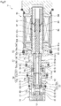
- the capacity control valve V mainly includes the first valve housing 10 and a second valve housing 11 which are formed of a metal material or a resin material and correspond to a valve housing, the first hollow rod 51, the pressure-sensitive valve member 52, the second hollow rod 54, and a differential CS valve body 90 which are disposed in the first valve housing 10 and the second valve housing 11 so as to be movable in a reciprocating manner in the axial direction, the pressure-sensitive body 61 which applies an urging force to the first hollow rod 51, the pressure-sensitive valve member 52, and the second hollow rod 54 rightward in the axial direction in response to the suction pressure Ps of the intermediate communication path 59, and the solenoid 80 which is connected to the second valve housing 11 and applies a drive force to the first hollow rod 51, the pressure-sensitive valve member 52, and the second hollow rod 54 and the differential CS valve body 90 is externally fitted to the first hollow rod 51 and is provided so as to be movable
- the solenoid 80 mainly includes a casing 81 which includes an opening portion 81a opening to the left side in the axial direction, a substantially cylindrical fixed iron core 82 which is inserted into the opening portion 81a of the casing 81 from the left side in the axial direction and is fixed to the inner radial side of the casing 81, a drive rod 83 which is disposed on the inner radial side of the fixed iron core 82 so as to be movable in a reciprocating manner in the axial direction so that the left axial end portion is connected and fixed to the second hollow rod 54, a movable iron core 84 which is fixed to the right axial end portion of the drive rod 83, a coil spring 85 which is provided between the fixed iron core 82 and the movable iron core 84 and urges the movable iron core 84 rightward in the axial direction, and an excitation coil 86 which is wound on the outside of the fixed iron core 82 with a bobbin interposed therebetween.
- the casing 81 is provided with a concave portion 81b of which an inner radial side of a left axial end is recessed rightward in the axial direction and a right axial end portion of the second valve housing 11 is inserted and fixed to the concave portion 81b in a substantially sealed state.
- the fixed iron core 82 is formed of a rigid body corresponding to a magnetic material such as iron or silicon steel and includes a cylindrical portion 82b which is provided with an insertion hole 82c extending in the axial direction so that the drive rod 83 is inserted therethrough and an annular flange portion 82d which extends outward in the radial direction from the outer peripheral surface of the left axial end portion of the cylindrical portion 82b and a sub-valve seat 82a is formed on a left axial end surface of the cylindrical portion 82b.
- the first valve housing 10 is provided with a concave portion 10c which is recessed from the radial center of the right axial end leftward in the axial direction and an insertion portion 11a formed in a left axial end portion of the second valve housing 11 is inserted and fitted thereto from the right side in the axial direction so as to be integrally connected and fixed thereto in a sealed state.
- the first valve housing 10 is provided with a Pd port 13 which corresponds to a discharge port communicating with the discharge chamber 2 of the variable displacement compressor M and a first Ps port 14 which corresponds to a suction port communicating with the suction chamber 3 of the variable displacement compressor M.
- the second valve housing 11 is provided with a first Pc port 15 which corresponds to a first control port and a control port located on the left side in the axial direction and communicating with the control chamber 4 of the variable displacement compressor M, a second Pc port 16 which corresponds to a second control port and a control port located on the right side in the axial direction, and a second Ps port 17 which corresponds to a suction port communicating with the suction chamber 3 of the variable displacement compressor M. That is, the first valve housing 10 and the second valve housing 11 are provided with the ports such that the second Ps port 17, the second Pc port 16, the first Pc port 15, the Pd port 13, and the first Ps port 14 are sequentially formed from the solenoid 80.
- a partition adjustment member 12 is press-inserted into a left axial end portion of the first valve housing 10 in a substantially sealed state so that the first valve housing has a substantially bottomed cylindrical shape.
- the partition adjustment member 12 can adjust the urging force of the pressure-sensitive body 61 by adjusting the installation position of the first valve housing 10 in the axial direction.
- the first hollow rod 51, the pressure-sensitive valve member 52, the second hollow rod 54, and the differential CS valve body 90 are disposed inside the first valve housing 10 and the second valve housing 11 so as to be movable in a reciprocating manner in the axial direction and a part of the inner peripheral surface of the first valve housing 10 is provided with a small-diameter guide surface 10b on which the outer peripheral surface of the pressure-sensitive valve member 52 is slidable in a substantially sealed state.
- a first valve chamber 20 which communicates with the Pd port 13 and in which the pressure-sensitive valve member 52 is disposed and a pressure-sensitive chamber 60 which communicates with the first Ps port 14 and in which the pressure-sensitive body 61 is disposed are formed in the first valve housing 10.
- a second valve chamber 30 (also referred to as a control pressure chamber) which communicates with the first Pc port 15 and the second Pc port 16 and in which the left axial end 51a of the first hollow rod 51 and the differential CS valve body 90 are disposed and a third valve chamber 40 which communicates with the second Ps port 17 and in which the second hollow rod 54 is disposed are formed in the second valve housing 11.
- the second valve chamber 30 is defined by the outer peripheral surfaces of the first hollow rod 51 and the differential CS valve body 90, the inner radial portion of the concave portion 10c of the first valve housing 10, and the inner peripheral surface on the left side in the axial direction in relation to a differential CS valve seat 11b formed on an inner peripheral surface of an annular protrusion extending toward the inner radial side of the second valve housing 11.
- the second valve chamber 30 is divided into a space 30A (a discharge side control chamber) and a space 30B (a suction side control chamber) by the differential CS valve body 90 in the axial direction.
- the first Pc port 15 can communicate the space 30A defined on the left side in the axial direction with a second cylindrical portion 90c of the differential CS valve body 90 to be described later interposed therebetween in the second valve chamber 30 with the control chamber 4 of the variable displacement compressor M and the second Pc port 16 can communicate the space 30B defined on the right sides in the axial direction with the control chamber 4 of the variable displacement compressor M (see FIGS. 3 to 5 ).
- the third valve chamber 40 is defined by the outer peripheral surfaces of the second hollow rod 54 and the drive rod 83, the left axial end surface of the fixed iron core 82, and the inner peripheral surface on the right side in the axial direction in relation to the differential CS valve seat 11b of the second valve housing 11.
- the pressure-sensitive body 61 mainly includes a bellows core 62 which has a coil spring 63 embedded therein and the disk-shaped cap 70 which is provided in the right axial end of the bellows core 62 and the left axial end of the bellows core 62 is fixed to the partition adjustment member 12.
- the pressure-sensitive body 61 is disposed in the pressure-sensitive chamber 60 and the seal surface 70a of the cap 70 sits on the pressure-sensitive valve seat 52a of the pressure-sensitive valve member 52 by an urging force of moving the cap 70 rightward in the axial direction by the coil spring 63 and the bellows core 62.
- the pressure-sensitive body 61 contracts by the high suction pressure Ps of the intermediate communication path 59 so that the pressure-sensitive valve 53 is opened.
- the valve opening degree of the primary valve 50 is slightly changed in response to the suction pressure Ps and hence capacity control depending on the situation of the refrigeration cycle can be performed.
- the refrigerant can be also discharged by the pressure drive valve 53 through the intermediate communication path 59 and a communication hole 83a of the drive rod 83 in addition to the second Ps port 17 at the startup, the refrigerant can be promptly discharged.
- the first hollow rod 51 is formed in a stepped cylindrical shape and a substantially turret shape in the side view including a cylindrical portion 51b to which the left axial end portion of the second hollow rod 54 is connected and fixed, an attachment portion 51c which is formed on the left side of the cylindrical portion 51b in the axial direction so as to have a diameter larger than that of the cylindrical portion 51b and to which a coil spring 91 corresponding to a spring is externally fitted, and a contact portion 51d which is formed on the left side of the attachment portion 51c in the axial direction so as to have a diameter larger than that of the attachment portion 51c and is provided with the left axial end 51a coming into contact with and separating from the primary valve seat 10a of the first valve housing 10.
- the first hollow rod 51 is provided with a concave portion 51e in which the inner radial side of the left axial end of the contact portion 51d is recessed rightward in the axial direction and an insertion portion 52b formed in the right axial end portion of the pressure-sensitive valve member 52 having a substantially cylindrical shape and a substantially turret shape in the side view is inserted and fitted from the left side in the axial direction so as to be connected and fixed thereto in a integrally sealed state.
- first hollow rod 51 is integrally connected and fixed in a sealed state by inserting and fitting the right axial end portion of the cylindrical portion 51b to a concave portion 54d in which the inner radial side of the left axial end of the second hollow rod 54 is recessed rightward in the axial direction from the left side in the axial direction.
- the intermediate communication path 59 which penetrates in the axial direction is formed inside the first hollow rod 51, the pressure-sensitive valve member 52, and the second hollow rod 54 by connecting the hollow holes. Additionally, the intermediate communication path 59 communicates with the third valve chamber 40 through the communication hole 83a formed in the left axial end portion of the drive rod 83 connected and fixed to the second hollow rod 54.
- the second hollow rod 54 is formed in a stepped cylindrical shape including a first cylindrical portion 54b which is disposed in the third valve chamber 40 and to which the left axial end portion of the drive rod 83 is connected and fixed and a second cylindrical portion 54c which is formed on the left side of the first cylindrical portion 54b in the axial direction so as to have a diameter smaller than that of the first cylindrical portion 54b.
- the outer peripheral surface of the second cylindrical portion 54c of the second hollow rod 54 and the differential CS valve seat 11b of the second valve housing 11 are separated from each other in the radial direction so that a flow path communicating a control fluid having passed through the second Pc port 16 and a suction fluid having passed through the second Ps port 17 with each other is formed.
- the differential CS valve 57 has a spool valve structure and includes the differential CS valve body 90 and the differential CS valve seat 11b formed on the inner peripheral surface of the second valve housing 11 and the differential CS valve 57 is opened and closed when a right axial end portion of a first cylindrical portion 90a of the differential CS valve body 90 is brought into contact with and separated from the differential CS valve seat 11b.
- the differential CS valve body 90 is formed in a stepped cylindrical shape and a substantially turret shape in the side view including the small-diameter first cylindrical portion 90a which is disposed in the second valve chamber 30 and is externally fitted to the cylindrical portion 51b of the first hollow rod 51, a taper portion 90b which extends from the left axial end of the first cylindrical portion 90a leftward in the axial direction so as to increase in diameter, and the second cylindrical portion 90c which is formed on the left side of the taper portion 90b in the axial direction so as to have a diameter larger than that of the first cylindrical portion 90a and is externally fitted to the attachment portion 51c and the cylindrical portion 51b of the first hollow rod 51 together with the coil spring 91.
- the inner peripheral surface of the first cylindrical portion 90a of the differential CS valve body 90 and the outer peripheral surface of the cylindrical portion 51b of the first hollow rod 51 are separated from each other in the radial direction so that a gap is formed therebetween and the differential CS valve body 90 is smoothly movable in the axial direction relative to the first hollow rod 51. Further, a gap 92 which is formed between the inner peripheral surface of the first cylindrical portion 90a of the differential CS valve body 90 and the outer peripheral surface of the cylindrical portion 51b of the first hollow rod 51 adjusts a pressure in a balanced state between the third valve chamber 40 and the space 30A defined on the left side of the second valve chamber 30 in the axial direction.
- the inside of the differential CS valve body 90 is formed in a stepped cylindrical shape in which the dimension of the inner diameter of the second cylindrical portion 90c is larger than that of the first cylindrical portion 90a and an annular surface 90d which extends outward in the radial direction from the left axial end of the inner peripheral surface of the first cylindrical portion 90a and extends continuously in a perpendicular direction is formed at an axial position corresponding to the substantial center of the taper portion 90b in the axial direction.
- the left axial end of the coil spring 91 is brought into contact with a side surface 51f which extends outward in the radial direction from the left axial end of the attachment portion 51c of the first hollow rod 51 and the right axial end of the coil spring 91 is brought into contact with the annular surface 90d corresponding to the inner surface of the differential CS valve body 90 externally fitted to the first hollow rod 51. That is, the differential CS valve body 90, the first hollow rod 51, the pressure-sensitive valve member 52, and the second hollow rod 54 are urged in the opposite axial directions by the coil spring 91. Additionally, the coil spring 91 is a compression spring and the outer periphery is separated from the inner peripheral surface of the second cylindrical portion 90c of the differential CS valve body 90 in the radial direction.
- the outer peripheral surface of the right axial end portion of the first cylindrical portion 90a of the differential CS valve body 90 is separated from the differential CS valve seat 11b formed in the second valve housing 11 in the radial direction and the outer peripheral surface of the second cylindrical portion 90c is separated from the inner peripheral surface of the second valve housing 11 in the radial direction so that a gap is formed therebetween. Accordingly, the differential CS valve body 90 is smoothly movable relative to the second valve housing 11 in the axial direction.
- the first cylindrical portion 90a of the differential CS valve body 90 moves in a reciprocating manner in the axial direction so as to change an overlapping amount with the differential CS valve seat 11b formed in the second valve housing 11 when viewed from the radial direction, thereby configuring the differential CS valve 57 that opens and closes the communication between the control fluid having passed through the second Pc port 16 and the suction fluid having passed through the second Ps port 17.
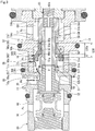
- the differential CS valve 57 is closed at a position in which the right axial end portion of the first cylindrical portion 90a of the differential CS valve body 90 overlaps the differential CS valve seat 11b when viewed from the radial direction (see FIGS. 3 and 4 ).
- the second cylindrical portion 90c of the differential CS valve body 90 moves in a reciprocating manner in the axial direction so as to change an overlapping position with the spool DC valve seat 11c formed on the inner peripheral surface on the left side of the differential CS valve seat 11b of the second valve housing 11 in the axial direction when viewed from the radial direction, thereby configuring a spool DC valve 58 that opens and closes the first Pc port 15 and the second Pc port 16.
- the spool DC valve 58 is configured to open the second Pc port 16 in a state in which the first Pc port 15 is closed by the left axial end portion of the second cylindrical portion 90c of the differential CS valve body 90 (see FIGS. 4 and 5 ) and to open the first Pc port 15 in a state in which the second Pc port 16 is closed by the right axial end portion of the second cylindrical portion 90c of the differential CS valve body 90 (see FIG. 3 ).
- annular groove 56 is formed in the outer periphery of the cylindrical portion 51b of the first hollow rod 51 by integrally connecting the first hollow rod 51 and the second hollow rod 54 to each other in a state in which the differential CS valve body 90 is externally fitted to the attachment portion 51c and the cylindrical portion 51b of the first hollow rod 51.
- the groove 56 is formed by the outer peripheral surface of the cylindrical portion 51b of the first hollow rod 51, a side surface 51g on the right side of the attachment portion 51c of the first hollow rod 51 in the axial direction, and a stopper portion 54e which corresponds to a movement regulation portion of the left axial end of the second hollow rod 54 and the axial position of the differential CS valve body 90 moving relative to the first hollow rod 51 in the axial direction is determined by the groove 56.
- the right axial end of the differential CS valve body 90 that is, the right axial end of the first cylindrical portion 90a is provided with an end surface portion 90e which is brought into contact with the stopper portion 54e of the left axial end surface of the second hollow rod 54 when the differential CS valve 57 is closed (see FIGS. 3 and 4 ), so that the axial position of the differential CS valve body 90 when closing the differential CS valve 57 is determined. Further, in the differential CS valve body 90, when the differential CS valve 57 is opened (see FIG.
- the annular surface 90d is brought into contact with the side surface 51g on the right side of the attachment portion 51c of the first hollow rod 51 in the axial direction, so that the axial position of the differential CS valve body 90 when opening the differential CS valve 57 is determined.
- the end surface portion 90e of the right axial end of the differential CS valve body 90 is separated from the stopper portion 54e of the second hollow rod 54 in the axial direction by the separation dimension A in a state in which the annular surface 90d on the left side of the differential CS valve body 90 in the axial direction is brought into contact with the side surface 51g on the right side of the attachment portion 51c of the first hollow rod 51 in the axial direction (see FIG. 5 ). That is, the differential CS valve body 90 is further movable in the axial direction by the separation dimension A regardless of the opening and closing of the primary valve 50.
- the opening and closing mechanism of the differential CS valve 57 will be described. Since the pressure receiving area is substantially the same between the pressure acting on the left side in the axial direction corresponding to the valve opening direction of the differential CS valve 57 and the pressure acting on the right side in the axial direction corresponding to the valve closing direction, the pressure applied from the space 30A on the left side in the axial direction to the differential CS valve body 90 and the pressure applied from the space 30B and the third valve chamber 40 on the right side in the axial direction thereto are balanced in a state in which the control pressure Pc of the control chamber 4 and the suction pressure Ps of the suction chamber 3 are balanced, so that the differential CS valve body 90 moves to the right side in the axial direction by receiving the urging force of the coil spring 91 and the differential CS valve 57 is closed (see FIGS. 3 and 4 ).
- the discharge pressure Pd, the control pressure Pc, and the suction pressure Ps are substantially balanced and the pressures applied from both sides in the axial direction to the differential CS valve body 90 are balanced.
- the differential CS valve body 90 moves rightward in the axial direction by receiving the urging force of the coil spring 91, the right axial end portion of the first cylindrical portion 90a of the differential CS valve body 90 overlaps the differential CS valve seat 11b of the second valve housing 11 when viewed from the radial direction so that the communication between the control fluid having passed through the second Pc port 16 and the suction fluid having passed through the second Ps port 17 is closed by the differential CS valve 57.
- the spool DC valve 58 opens the first Pc port 15 and closes the second Pc port 16 so that the flow of the control fluid into the space 30B of the second valve chamber 30 through the second Pc port 16 is prevented.
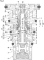
- variable displacement compressor M is started and the solenoid 80 of the capacity control valve V is energized so that the primary valve 50 is closed and the sub-valve 55 is opened (see FIG. 4 ). Further, the differential CS valve body 90 is maintained in the closed state since the end surface portion 90e of the right axial end is pressed by the stopper portion 54e of the second hollow rod 54 and the first hollow rod 51, the pressure-sensitive valve member 52, and the second hollow rod 54 are moved leftward in the axial direction together.
- the left axial end portion of the second cylindrical portion 90c of the differential CS valve body 90 closes the first Pc port 15 and slightly opens the second Pc port 16 so that the flow of the discharge fluid into the space 30A on the left side of the second valve chamber 30 in the axial direction through the primary valve 50 and the flow of the control fluid thereinto through the first Pc port 15 are prevented.
- a blow-by gas flows into the control chamber 4 in accordance with the startup of the variable displacement compressor M and the control fluid pressurized from the balanced state flows through the second Pc port 16 so that the control pressure Pc in the space 30B on the right side of the second valve chamber 30 in the axial direction increases and the control pressure Pc in the space 30A on the left side of the second valve chamber 30 in the axial direction relatively decreases.
- the control pressure Pc applied from the space 30A on the left side in the axial direction to the differential CS valve body 90 becomes smaller than the control pressure Pc applied from the space 30B on the right side in the axial direction so that a differential pressure is generated in the axial direction, a force (indicated by a white arrow in FIG. 5 ) of moving the differential CS valve body 90 leftward in the axial direction is generated, the differential CS valve body 90 relatively moves leftward in the axial direction relative to the first hollow rod 51, the pressure-sensitive valve member 52, and the second hollow rod 54 against the urging force of the coil spring 91, the differential CS valve 57 is opened, and the second Pc port 16 is fully opened by the spool DC valve 58.
- the differential CS valve 57 is closed, the flow rate of the flow path connecting the second Pc port 16 to the second Ps port 17 is reduced, and the control fluid having passed through the second Pc port 16 is prevented from flowing to the second Ps port 17. According, the controllability of the control pressure Pc of the control chamber 4 is excellent and the operation efficiency of the variable displacement compressor M can be improved (see FIGS. 3 and 4 ). In other words, the opening and closing of the primary valve 50 can be controlled while the differential CS valve 57 is closed.
- the capacity control valve V can have a simple structure.
- the left axial end of the differential CS valve body 90 constituting the spool DC valve 58 that is, the left axial end of the second cylindrical portion 90c is formed so as to be flush with the left axial end of the opening portion of the first Pc port 15 in the radial direction while the primary valve 50 is closed and the differential CS valve 57 is closed, the flow path for discharging a fluid from the Pd port 13 to the first Pc port 15 through the space 30A is reliably formed even when the primary valve 50 is slightly opened by the duty control of the capacity control valve V. Accordingly, the controllability of the control pressure Pc of the control chamber 4 is excellent and the operation efficiency of the variable displacement compressor M can be improved.
- the differential CS valve 57 is moved by the differential pressure and the second Pc port 16 communicates with the second Ps port 17 through the space 30B, so that the control pressure Pc of the control chamber 4 can be maintained low.
- the differential CS valve 57 is formed in a spool valve structure by the right axial end portion of the first cylindrical portion 90a of the differential CS valve body 90 and the differential CS valve seat 11b formed on the inner peripheral surface of the second valve housing 11, the differential CS valve 57 is closed when the first hollow rod 51, the pressure-sensitive valve member 52, and the second hollow rod 54 are stroked by a predetermined amount or more in the axial direction. Accordingly, the differential CS valve 57 can be reliably closed.
- the differential CS valve 57 is maintained in the closed state even when the first hollow rod 51, the pressure-sensitive valve member 52, and the second hollow rod 54 are slightly moved in the axial direction due to disturbances such as vibration, for example, during normal control, the capacity control valve V is strong against disturbance and has excellent control accuracy.
- first Pc port 15 communicating with the space 30A on the left side of the second valve chamber 30 in the axial direction is provided adjacent to the second Pc port 16 communicating with the space 30B on the right side of the second valve chamber 30 in the axial direction and the first Pc port 15 and the second Pc port 16 is separated from each other by an axial dimension L10d of a partition wall 10d of the first valve housing 10 in the axial direction as illustrated in an enlarged part of FIG.
- the axial dimension L90c of the second cylindrical portion 90c of the differential CS valve body 90 is formed to be larger than the axial dimension of each of the first Pc port 15 and the second Pc port 16 (L90c > L15, L16).
- each of the first Pc port 15 and the second Pc port 16 can be opened by the second cylindrical portion 90c when the differential CS valve body 90 is moved in the axial direction and both the first Pc port 15 and the second Pc port 16 can be slightly opened when the second cylindrical portion 90c is moved to the substantial center of the formation range of the first Pc port 15 and the second Pc port 16 in the axial direction, the opening and closing of two ports of the first Pc port 15 and the second Pc port 16 can be controlled by one differential CS valve body 90 and hence the capacity control valve V can have a simple structure.
- partition wall 10d between the first Pc port 15 and the second Pc port 16 is not essential, but when the partition wall 10d is provided, one of the first Pc port 15 and the second Pc port 16 can be opened and the other of them can be closed in a reliable and simple manner.
- the differential pressure may be increased by securing the large flow path cross-sectional area of the gap 92 in such a manner that the inner peripheral surface of the first cylindrical portion 90a of the differential CS valve body 90 is provided with a slit 90f corresponding to a groove extending in the axial direction and the right axial end of the first cylindrical portion 90a is provided with a slit 90g corresponding to a groove extending in the radial direction. Additionally, a slit may be provided in the outer peripheral surface of the cylindrical portion 51b of the first hollow rod 51 in order to increase the flow path cross-sectional area of the gap 92.
- the gap 92 functions as a pilot passage for moving the differential CS valve body 90 and the differential CS valve 57 is opened, the effective flow passage area communicating the second Pc port 16 with the second Ps port 17 largely increases from the area of the gap 92.
- the invention is not limited thereto and the first cylindrical portion 90a of the differential CS valve body 90 may be provided with a through-hole extending in the axial direction.
- a through-hole extending in the radial direction may be formed in the attachment portion 51c or the cylindrical portion 51b of the first hollow rod 51 so as to communicate the space 30A, the intermediate communication path 59 formed on the inside of the first hollow rod 51, and the space 30A defined on the left side in the axial direction of the second valve chamber 30 with one another.
- first hollow rod 51 and the pressure-sensitive valve member 52 are separate members, but both members may be integrated with each other.
- a fixed orifice and a communication path directly communicating the control chamber 4 of the variable displacement compressor M with the suction chamber 3 may not be provided.
- the sub-valve may not be provided and the right axial end of the second hollow rod does not need to have a sealing function when the right axial end functions as a support member that receives an axial load.
- the coil spring 91 is not limited to a compression spring, but may be a tension spring or may have a shape other than a coil shape.
- first valve housing 10 and the second valve housing 11 may be integrated with each other.
- the pressure-sensitive body 61 may not use a coil spring therein.
Landscapes
- Engineering & Computer Science (AREA)
- General Engineering & Computer Science (AREA)
- Mechanical Engineering (AREA)
- Compressors, Vaccum Pumps And Other Relevant Systems (AREA)
Applications Claiming Priority (2)
| Application Number | Priority Date | Filing Date | Title |
|---|---|---|---|
| JP2018133236 | 2018-07-13 | ||
| PCT/JP2019/027112 WO2020013169A1 (ja) | 2018-07-13 | 2019-07-09 | 容量制御弁 |
Publications (3)
| Publication Number | Publication Date |
|---|---|
| EP3822485A1 true EP3822485A1 (de) | 2021-05-19 |
| EP3822485A4 EP3822485A4 (de) | 2022-03-23 |
| EP3822485B1 EP3822485B1 (de) | 2024-04-10 |
Family
ID=69142441
Family Applications (1)
| Application Number | Title | Priority Date | Filing Date |
|---|---|---|---|
| EP19834984.7A Active EP3822485B1 (de) | 2018-07-13 | 2019-07-09 | Kapazitätssteuerungsventil |
Country Status (5)
| Country | Link |
|---|---|
| US (1) | US11480166B2 (de) |
| EP (1) | EP3822485B1 (de) |
| JP (1) | JP7191957B2 (de) |
| CN (1) | CN112424473B (de) |
| WO (1) | WO2020013169A1 (de) |
Cited By (1)
| Publication number | Priority date | Publication date | Assignee | Title |
|---|---|---|---|---|
| CN111712638A (zh) * | 2018-02-15 | 2020-09-25 | 伊格尔工业股份有限公司 | 容量控制阀 |
Families Citing this family (6)
| Publication number | Priority date | Publication date | Assignee | Title |
|---|---|---|---|---|
| EP3916224A4 (de) * | 2019-01-21 | 2022-10-19 | Eagle Industry Co., Ltd. | Kapazitätssteuerungsventil |
| WO2020204134A1 (ja) * | 2019-04-03 | 2020-10-08 | イーグル工業株式会社 | 容量制御弁 |
| KR20210142158A (ko) | 2019-04-03 | 2021-11-24 | 이구루코교 가부시기가이샤 | 용량 제어 밸브 |
| CN113692510B (zh) | 2019-04-24 | 2023-07-04 | 伊格尔工业股份有限公司 | 容量控制阀 |
| CN116157609A (zh) * | 2020-08-04 | 2023-05-23 | 伊格尔工业股份有限公司 | 阀 |
| JPWO2023002887A1 (de) * | 2021-07-20 | 2023-01-26 |
Family Cites Families (63)
| Publication number | Priority date | Publication date | Assignee | Title |
|---|---|---|---|---|
| JPS5862775A (ja) | 1981-10-08 | 1983-04-14 | Sankyo Seiki Mfg Co Ltd | 磁気ストライプ付カ−ドの処理装置 |
| JP3089816B2 (ja) * | 1992-04-28 | 2000-09-18 | 株式会社豊田自動織機製作所 | 斜板式可変容量圧縮機 |
| JPH06200875A (ja) * | 1993-01-08 | 1994-07-19 | Toyota Autom Loom Works Ltd | 揺動斜板式可変容量圧縮機 |
| JP3242496B2 (ja) | 1993-07-06 | 2001-12-25 | 株式会社豊田自動織機 | 可変容量圧縮機の外部切換式容量制御弁 |
| JPH09144929A (ja) | 1995-11-16 | 1997-06-03 | Tosok Corp | 電磁弁 |
| US6010312A (en) | 1996-07-31 | 2000-01-04 | Kabushiki Kaisha Toyoda Jidoshokki Seiksakusho | Control valve unit with independently operable valve mechanisms for variable displacement compressor |
| JP3583951B2 (ja) | 1999-06-07 | 2004-11-04 | 株式会社豊田自動織機 | 容量制御弁 |
| JP2001073939A (ja) | 1999-08-31 | 2001-03-21 | Toyota Autom Loom Works Ltd | 容量可変型圧縮機の制御弁及び容量可変型圧縮機 |
| JP2001099060A (ja) * | 1999-10-04 | 2001-04-10 | Fuji Koki Corp | 可変容量型圧縮機用制御弁 |
| JP2001132632A (ja) | 1999-11-10 | 2001-05-18 | Toyota Autom Loom Works Ltd | 容量可変型圧縮機の制御弁 |
| JP3942851B2 (ja) | 2001-07-31 | 2007-07-11 | 株式会社テージーケー | 容量制御弁 |
| JP4242624B2 (ja) | 2002-09-26 | 2009-03-25 | イーグル工業株式会社 | 容量制御弁及びその制御方法 |
| JP4316955B2 (ja) | 2003-08-11 | 2009-08-19 | イーグル工業株式会社 | 容量制御弁 |
| JP2006097665A (ja) * | 2004-06-28 | 2006-04-13 | Toyota Industries Corp | 可変容量型圧縮機における容量制御弁 |
| JP4431462B2 (ja) | 2004-08-10 | 2010-03-17 | 株式会社鷺宮製作所 | 斜板式容量可変型圧縮機および電磁制御弁 |
| WO2006090760A1 (ja) | 2005-02-24 | 2006-08-31 | Kabushiki Kaisha Toyota Jidoshokki | 容量制御弁 |
| JP2006307828A (ja) | 2005-03-31 | 2006-11-09 | Tgk Co Ltd | 可変容量圧縮機用制御弁 |
| JP2007247512A (ja) | 2006-03-15 | 2007-09-27 | Toyota Industries Corp | 可変容量型圧縮機における容量制御弁 |
| JP5167121B2 (ja) | 2006-03-15 | 2013-03-21 | イーグル工業株式会社 | 容量制御弁 |
| JP2008014269A (ja) | 2006-07-07 | 2008-01-24 | Toyota Industries Corp | 可変容量型圧縮機の容量制御弁 |
| JP2008202572A (ja) | 2007-02-22 | 2008-09-04 | Toyota Industries Corp | 可変容量型圧縮機における容量制御弁 |
| US8387124B2 (en) | 2007-03-15 | 2013-02-26 | Palo Alto Research Center Incorporated | Wormhole devices for usable secure access to remote resource |
| JP4861956B2 (ja) | 2007-10-24 | 2012-01-25 | 株式会社豊田自動織機 | 可変容量型圧縮機における容量制御弁 |
| JP5499254B2 (ja) * | 2009-07-09 | 2014-05-21 | 株式会社テージーケー | 可変容量圧縮機用制御弁 |
| JP2011032916A (ja) | 2009-07-31 | 2011-02-17 | Tgk Co Ltd | 制御弁 |
| KR101099121B1 (ko) | 2009-08-19 | 2011-12-27 | 주식회사 두원전자 | 진공 벨로우즈 조립체 제조방법 |
| EP2549106B1 (de) | 2010-03-16 | 2019-10-16 | Eagle Industry Co., Ltd. | Volumensteuerungsventil |
| KR101319566B1 (ko) | 2010-04-29 | 2013-10-23 | 이구루코교 가부시기가이샤 | 용량 제어 밸브 |
| JP5665722B2 (ja) | 2011-11-17 | 2015-02-04 | 株式会社豊田自動織機 | 容量制御弁 |
| KR101322404B1 (ko) | 2012-01-19 | 2013-10-28 | (주)대정고분자산업 | 가변용량 압축기의 전자제어밸브 |
| WO2013176012A1 (ja) | 2012-05-24 | 2013-11-28 | イーグル工業株式会社 | 容量制御弁 |
| JP6064132B2 (ja) | 2012-10-09 | 2017-01-25 | 株式会社テージーケー | 複合弁 |
| WO2014091975A1 (ja) | 2012-12-12 | 2014-06-19 | イーグル工業株式会社 | 容量制御弁 |
| JP6020130B2 (ja) | 2012-12-19 | 2016-11-02 | 株式会社豊田自動織機 | 可変容量型斜板式圧縮機 |
| US9777863B2 (en) | 2013-01-31 | 2017-10-03 | Eagle Industry Co., Ltd. | Capacity control valve |
| JP6103586B2 (ja) | 2013-03-27 | 2017-03-29 | 株式会社テージーケー | 可変容量圧縮機用制御弁 |
| JP6149239B2 (ja) | 2013-06-28 | 2017-06-21 | 株式会社テージーケー | 可変容量圧縮機用制御弁 |
| JP6206274B2 (ja) | 2014-03-19 | 2017-10-04 | 株式会社豊田自動織機 | 容量制御弁 |
| JP6200875B2 (ja) | 2014-09-30 | 2017-09-20 | 株式会社三共 | 遊技機 |
| CN107002900B (zh) | 2014-12-25 | 2019-03-12 | 伊格尔工业股份有限公司 | 容量控制阀 |
| WO2016152959A1 (ja) * | 2015-03-26 | 2016-09-29 | 株式会社ヴァレオジャパン | 可変容量型圧縮機 |
| JP6500183B2 (ja) | 2015-04-02 | 2019-04-17 | 株式会社テージーケー | 可変容量圧縮機用制御弁 |
| US20170028462A1 (en) | 2015-07-28 | 2017-02-02 | Primetals Technologies USA LLC | Simple copper tube design for continuous casting process with enhanced rigidity |
| JPWO2017057160A1 (ja) | 2015-09-29 | 2018-07-12 | 株式会社ヴァレオジャパン | 可変容量型圧縮機の制御弁 |
| JP6383720B2 (ja) | 2015-12-16 | 2018-08-29 | 株式会社不二工機 | 可変容量型圧縮機用制御弁 |
| JP6663227B2 (ja) | 2016-01-19 | 2020-03-11 | サンデン・オートモーティブコンポーネント株式会社 | 可変容量圧縮機の容量制御弁 |
| JP6500186B2 (ja) | 2016-02-25 | 2019-04-17 | 株式会社テージーケー | 可変容量圧縮機用制御弁 |
| CN108779768B (zh) | 2016-03-17 | 2020-05-12 | 伊格尔工业股份有限公司 | 容量控制阀 |
| CN108071824B (zh) | 2016-06-13 | 2021-08-10 | 株式会社Tgk | 可变容量压缩机用控制阀 |
| JP6714274B2 (ja) | 2016-06-13 | 2020-06-24 | 株式会社テージーケー | 可変容量圧縮機用制御弁 |
| JP2018021646A (ja) | 2016-08-05 | 2018-02-08 | 株式会社鷺宮製作所 | 感圧制御弁 |
| JP2018040385A (ja) | 2016-09-05 | 2018-03-15 | 株式会社テージーケー | 電磁弁 |
| CN110114573B (zh) | 2016-12-28 | 2021-06-29 | 伊格尔工业股份有限公司 | 容量控制阀 |
| JP2018145877A (ja) | 2017-03-06 | 2018-09-20 | 株式会社豊田自動織機 | 可変容量型斜板式圧縮機 |
| JP6924476B2 (ja) | 2017-04-07 | 2021-08-25 | 株式会社テージーケー | 可変容量圧縮機用制御弁 |
| JP6997536B2 (ja) | 2017-05-09 | 2022-01-17 | サンデン・オートモーティブコンポーネント株式会社 | ソレノイド制御弁及びこれを備えた可変容量圧縮機 |
| JP2019002384A (ja) | 2017-06-19 | 2019-01-10 | サンデン・オートモーティブコンポーネント株式会社 | 可変容量圧縮機 |
| US11512786B2 (en) | 2017-11-30 | 2022-11-29 | Eagle Industry Co., Ltd. | Capacity control valve and control method for capacity control valve |
| WO2019146674A1 (ja) | 2018-01-26 | 2019-08-01 | イーグル工業株式会社 | 容量制御弁 |
| US11873804B2 (en) | 2018-02-27 | 2024-01-16 | Eagle Industry Co., Ltd. | Capacity control valve |
| JP7387237B2 (ja) | 2018-08-08 | 2023-11-28 | イーグル工業株式会社 | 容量制御弁 |
| US11053933B2 (en) | 2018-12-13 | 2021-07-06 | Eagle Industry Co., Ltd. | Displacement control valve |
| US11300219B2 (en) | 2020-07-28 | 2022-04-12 | Mahle International Gmbh | Variable-capacity compressor control valve |
-
2019
- 2019-07-09 JP JP2020530191A patent/JP7191957B2/ja active Active
- 2019-07-09 EP EP19834984.7A patent/EP3822485B1/de active Active
- 2019-07-09 US US17/256,953 patent/US11480166B2/en active Active
- 2019-07-09 CN CN201980044077.XA patent/CN112424473B/zh active Active
- 2019-07-09 WO PCT/JP2019/027112 patent/WO2020013169A1/ja unknown
Cited By (2)
| Publication number | Priority date | Publication date | Assignee | Title |
|---|---|---|---|---|
| CN111712638A (zh) * | 2018-02-15 | 2020-09-25 | 伊格尔工业股份有限公司 | 容量控制阀 |
| CN111712638B (zh) * | 2018-02-15 | 2022-05-03 | 伊格尔工业股份有限公司 | 容量控制阀 |
Also Published As
| Publication number | Publication date |
|---|---|
| JPWO2020013169A1 (ja) | 2021-07-15 |
| JP7191957B2 (ja) | 2022-12-19 |
| US11480166B2 (en) | 2022-10-25 |
| US20210123422A1 (en) | 2021-04-29 |
| CN112424473A (zh) | 2021-02-26 |
| WO2020013169A1 (ja) | 2020-01-16 |
| CN112424473B (zh) | 2023-02-28 |
| EP3822485A4 (de) | 2022-03-23 |
| EP3822485B1 (de) | 2024-04-10 |
Similar Documents
| Publication | Publication Date | Title |
|---|---|---|
| EP3822485B1 (de) | Kapazitätssteuerungsventil | |
| EP3760864B1 (de) | Kapazitätssteuerungsventil | |
| CN113474553B (zh) | 排量控制阀 | |
| WO2020032087A1 (ja) | 容量制御弁 | |
| EP3754190B1 (de) | Kapazitätssteuerungsventil | |
| US11555489B2 (en) | Capacity control valve | |
| EP4148274B1 (de) | Kapazitätssteuerungsventil | |
| CN113661324B (zh) | 容量控制阀 | |
| EP3879150B1 (de) | Kapazitätssteuerungsventil | |
| EP3822483B1 (de) | Kapazitätssteuerungsventil | |
| US11994120B2 (en) | Capacity control valve | |
| EP4141259A1 (de) | Mengensteuerventil | |
| WO2020116436A1 (ja) | 容量制御弁 |
Legal Events
| Date | Code | Title | Description |
|---|---|---|---|
| STAA | Information on the status of an ep patent application or granted ep patent |
Free format text: STATUS: THE INTERNATIONAL PUBLICATION HAS BEEN MADE |
|
| STAA | Information on the status of an ep patent application or granted ep patent |
Free format text: STATUS: THE INTERNATIONAL PUBLICATION HAS BEEN MADE |
|
| PUAI | Public reference made under article 153(3) epc to a published international application that has entered the european phase |
Free format text: ORIGINAL CODE: 0009012 |
|
| STAA | Information on the status of an ep patent application or granted ep patent |
Free format text: STATUS: REQUEST FOR EXAMINATION WAS MADE |
|
| 17P | Request for examination filed |
Effective date: 20210111 |
|
| AK | Designated contracting states |
Kind code of ref document: A1 Designated state(s): AL AT BE BG CH CY CZ DE DK EE ES FI FR GB GR HR HU IE IS IT LI LT LU LV MC MK MT NL NO PL PT RO RS SE SI SK SM TR |
|
| DAV | Request for validation of the european patent (deleted) | ||
| DAX | Request for extension of the european patent (deleted) | ||
| A4 | Supplementary search report drawn up and despatched |
Effective date: 20220221 |
|
| RIC1 | Information provided on ipc code assigned before grant |
Ipc: F04B 27/10 20060101ALI20220215BHEP Ipc: F16K 31/06 20060101ALI20220215BHEP Ipc: F16K 11/20 20060101ALI20220215BHEP Ipc: F04B 27/18 20060101AFI20220215BHEP |
|
| GRAP | Despatch of communication of intention to grant a patent |
Free format text: ORIGINAL CODE: EPIDOSNIGR1 |
|
| STAA | Information on the status of an ep patent application or granted ep patent |
Free format text: STATUS: GRANT OF PATENT IS INTENDED |
|
| INTG | Intention to grant announced |
Effective date: 20231205 |
|
| GRAS | Grant fee paid |
Free format text: ORIGINAL CODE: EPIDOSNIGR3 |
|
| GRAA | (expected) grant |
Free format text: ORIGINAL CODE: 0009210 |
|
| STAA | Information on the status of an ep patent application or granted ep patent |
Free format text: STATUS: THE PATENT HAS BEEN GRANTED |
|
| AK | Designated contracting states |
Kind code of ref document: B1 Designated state(s): AL AT BE BG CH CY CZ DE DK EE ES FI FR GB GR HR HU IE IS IT LI LT LU LV MC MK MT NL NO PL PT RO RS SE SI SK SM TR |
|
| REG | Reference to a national code |
Ref country code: GB Ref legal event code: FG4D |
|
| REG | Reference to a national code |
Ref country code: CH Ref legal event code: EP |
|
| REG | Reference to a national code |
Ref country code: DE Ref legal event code: R096 Ref document number: 602019050160 Country of ref document: DE |
|
| REG | Reference to a national code |
Ref country code: IE Ref legal event code: FG4D |