EP3821967B1 - Système d'épuration d'air et cartouches - Google Patents
Système d'épuration d'air et cartouches Download PDFInfo
- Publication number
- EP3821967B1 EP3821967B1 EP20194255.4A EP20194255A EP3821967B1 EP 3821967 B1 EP3821967 B1 EP 3821967B1 EP 20194255 A EP20194255 A EP 20194255A EP 3821967 B1 EP3821967 B1 EP 3821967B1
- Authority
- EP
- European Patent Office
- Prior art keywords
- end cap
- projection
- support
- cartridge
- central
- Prior art date
- Legal status (The legal status is an assumption and is not a legal conclusion. Google has not performed a legal analysis and makes no representation as to the accuracy of the status listed.)
- Active
Links
- WYTGDNHDOZPMIW-RCBQFDQVSA-N alstonine Natural products C1=CC2=C3C=CC=CC3=NC2=C2N1C[C@H]1[C@H](C)OC=C(C(=O)OC)[C@H]1C2 WYTGDNHDOZPMIW-RCBQFDQVSA-N 0.000 claims description 53
- 238000009434 installation Methods 0.000 description 18
- 230000002093 peripheral effect Effects 0.000 description 10
- 238000001914 filtration Methods 0.000 description 8
- 230000003993 interaction Effects 0.000 description 7
- 230000000712 assembly Effects 0.000 description 6
- 238000000429 assembly Methods 0.000 description 6
- 239000004033 plastic Substances 0.000 description 6
- 229920003023 plastic Polymers 0.000 description 6
- 239000000853 adhesive Substances 0.000 description 5
- 230000001070 adhesive effect Effects 0.000 description 5
- 239000000463 material Substances 0.000 description 5
- 229920002635 polyurethane Polymers 0.000 description 5
- 239000004814 polyurethane Substances 0.000 description 5
- 230000008901 benefit Effects 0.000 description 3
- 239000002131 composite material Substances 0.000 description 3
- 239000002184 metal Substances 0.000 description 3
- 238000000034 method Methods 0.000 description 3
- 238000004382 potting Methods 0.000 description 3
- 239000011324 bead Substances 0.000 description 2
- 238000002485 combustion reaction Methods 0.000 description 2
- 230000001419 dependent effect Effects 0.000 description 2
- 230000002401 inhibitory effect Effects 0.000 description 2
- 238000000465 moulding Methods 0.000 description 2
- 238000007789 sealing Methods 0.000 description 2
- 239000004743 Polypropylene Substances 0.000 description 1
- 229920005830 Polyurethane Foam Polymers 0.000 description 1
- 230000001154 acute effect Effects 0.000 description 1
- 238000012512 characterization method Methods 0.000 description 1
- 238000004891 communication Methods 0.000 description 1
- 230000006835 compression Effects 0.000 description 1
- 238000007906 compression Methods 0.000 description 1
- 238000010276 construction Methods 0.000 description 1
- 239000000428 dust Substances 0.000 description 1
- 239000011521 glass Substances 0.000 description 1
- 238000003780 insertion Methods 0.000 description 1
- 230000037431 insertion Effects 0.000 description 1
- 239000000203 mixture Substances 0.000 description 1
- 239000002991 molded plastic Substances 0.000 description 1
- -1 polypropylene Polymers 0.000 description 1
- 229920001155 polypropylene Polymers 0.000 description 1
- 239000011496 polyurethane foam Substances 0.000 description 1
- 230000003014 reinforcing effect Effects 0.000 description 1
- 239000007787 solid Substances 0.000 description 1
- XLYOFNOQVPJJNP-UHFFFAOYSA-N water Substances O XLYOFNOQVPJJNP-UHFFFAOYSA-N 0.000 description 1
Images


Classifications
-
- B—PERFORMING OPERATIONS; TRANSPORTING
- B01—PHYSICAL OR CHEMICAL PROCESSES OR APPARATUS IN GENERAL
- B01D—SEPARATION
- B01D46/00—Filters or filtering processes specially modified for separating dispersed particles from gases or vapours
-
- B—PERFORMING OPERATIONS; TRANSPORTING
- B01—PHYSICAL OR CHEMICAL PROCESSES OR APPARATUS IN GENERAL
- B01D—SEPARATION
- B01D46/00—Filters or filtering processes specially modified for separating dispersed particles from gases or vapours
- B01D46/24—Particle separators, e.g. dust precipitators, using rigid hollow filter bodies
- B01D46/2403—Particle separators, e.g. dust precipitators, using rigid hollow filter bodies characterised by the physical shape or structure of the filtering element
- B01D46/2411—Filter cartridges
- B01D46/2414—End caps including additional functions or special forms
-
- B—PERFORMING OPERATIONS; TRANSPORTING
- B01—PHYSICAL OR CHEMICAL PROCESSES OR APPARATUS IN GENERAL
- B01D—SEPARATION
- B01D46/00—Filters or filtering processes specially modified for separating dispersed particles from gases or vapours
- B01D46/0002—Casings; Housings; Frame constructions
-
- B—PERFORMING OPERATIONS; TRANSPORTING
- B01—PHYSICAL OR CHEMICAL PROCESSES OR APPARATUS IN GENERAL
- B01D—SEPARATION
- B01D46/00—Filters or filtering processes specially modified for separating dispersed particles from gases or vapours
- B01D46/0002—Casings; Housings; Frame constructions
- B01D46/0004—Details of removable closures, lids, caps or filter heads
-
- B—PERFORMING OPERATIONS; TRANSPORTING
- B01—PHYSICAL OR CHEMICAL PROCESSES OR APPARATUS IN GENERAL
- B01D—SEPARATION
- B01D46/00—Filters or filtering processes specially modified for separating dispersed particles from gases or vapours
- B01D46/0002—Casings; Housings; Frame constructions
- B01D46/0005—Mounting of filtering elements within casings, housings or frames
-
- B—PERFORMING OPERATIONS; TRANSPORTING
- B01—PHYSICAL OR CHEMICAL PROCESSES OR APPARATUS IN GENERAL
- B01D—SEPARATION
- B01D46/00—Filters or filtering processes specially modified for separating dispersed particles from gases or vapours
- B01D46/0002—Casings; Housings; Frame constructions
- B01D46/0012—In-line filters
-
- B—PERFORMING OPERATIONS; TRANSPORTING
- B01—PHYSICAL OR CHEMICAL PROCESSES OR APPARATUS IN GENERAL
- B01D—SEPARATION
- B01D46/00—Filters or filtering processes specially modified for separating dispersed particles from gases or vapours
- B01D46/0002—Casings; Housings; Frame constructions
- B01D46/0013—Modules
-
- B—PERFORMING OPERATIONS; TRANSPORTING
- B01—PHYSICAL OR CHEMICAL PROCESSES OR APPARATUS IN GENERAL
- B01D—SEPARATION
- B01D46/00—Filters or filtering processes specially modified for separating dispersed particles from gases or vapours
- B01D46/0084—Filters or filtering processes specially modified for separating dispersed particles from gases or vapours provided with safety means
- B01D46/009—Identification of filter type or position thereof, e.g. by transponders or bar codes
-
- B—PERFORMING OPERATIONS; TRANSPORTING
- B01—PHYSICAL OR CHEMICAL PROCESSES OR APPARATUS IN GENERAL
- B01D—SEPARATION
- B01D46/00—Filters or filtering processes specially modified for separating dispersed particles from gases or vapours
- B01D46/24—Particle separators, e.g. dust precipitators, using rigid hollow filter bodies
- B01D46/2403—Particle separators, e.g. dust precipitators, using rigid hollow filter bodies characterised by the physical shape or structure of the filtering element
- B01D46/2411—Filter cartridges
-
- B—PERFORMING OPERATIONS; TRANSPORTING
- B01—PHYSICAL OR CHEMICAL PROCESSES OR APPARATUS IN GENERAL
- B01D—SEPARATION
- B01D46/00—Filters or filtering processes specially modified for separating dispersed particles from gases or vapours
- B01D46/42—Auxiliary equipment or operation thereof
-
- B—PERFORMING OPERATIONS; TRANSPORTING
- B01—PHYSICAL OR CHEMICAL PROCESSES OR APPARATUS IN GENERAL
- B01D—SEPARATION
- B01D46/00—Filters or filtering processes specially modified for separating dispersed particles from gases or vapours
- B01D46/56—Filters or filtering processes specially modified for separating dispersed particles from gases or vapours with multiple filtering elements, characterised by their mutual disposition
- B01D46/62—Filters or filtering processes specially modified for separating dispersed particles from gases or vapours with multiple filtering elements, characterised by their mutual disposition connected in series
- B01D46/64—Filters or filtering processes specially modified for separating dispersed particles from gases or vapours with multiple filtering elements, characterised by their mutual disposition connected in series arranged concentrically or coaxially
-
- B—PERFORMING OPERATIONS; TRANSPORTING
- B01—PHYSICAL OR CHEMICAL PROCESSES OR APPARATUS IN GENERAL
- B01D—SEPARATION
- B01D46/00—Filters or filtering processes specially modified for separating dispersed particles from gases or vapours
- B01D46/88—Replacing filter elements
-
- F—MECHANICAL ENGINEERING; LIGHTING; HEATING; WEAPONS; BLASTING
- F02—COMBUSTION ENGINES; HOT-GAS OR COMBUSTION-PRODUCT ENGINE PLANTS
- F02M—SUPPLYING COMBUSTION ENGINES IN GENERAL WITH COMBUSTIBLE MIXTURES OR CONSTITUENTS THEREOF
- F02M35/00—Combustion-air cleaners, air intakes, intake silencers, or induction systems specially adapted for, or arranged on, internal-combustion engines
- F02M35/02—Air cleaners
- F02M35/024—Air cleaners using filters, e.g. moistened
- F02M35/02416—Fixing, mounting, supporting or arranging filter elements; Filter element cartridges
-
- B—PERFORMING OPERATIONS; TRANSPORTING
- B01—PHYSICAL OR CHEMICAL PROCESSES OR APPARATUS IN GENERAL
- B01D—SEPARATION
- B01D2265/00—Casings, housings or mounting for filters specially adapted for separating dispersed particles from gases or vapours
- B01D2265/02—Non-permanent measures for connecting different parts of the filter
- B01D2265/021—Anti-rotational means
-
- B—PERFORMING OPERATIONS; TRANSPORTING
- B01—PHYSICAL OR CHEMICAL PROCESSES OR APPARATUS IN GENERAL
- B01D—SEPARATION
- B01D2265/00—Casings, housings or mounting for filters specially adapted for separating dispersed particles from gases or vapours
- B01D2265/02—Non-permanent measures for connecting different parts of the filter
- B01D2265/024—Mounting aids
- B01D2265/026—Mounting aids with means for avoiding false mounting
-
- B—PERFORMING OPERATIONS; TRANSPORTING
- B01—PHYSICAL OR CHEMICAL PROCESSES OR APPARATUS IN GENERAL
- B01D—SEPARATION
- B01D2265/00—Casings, housings or mounting for filters specially adapted for separating dispersed particles from gases or vapours
- B01D2265/02—Non-permanent measures for connecting different parts of the filter
- B01D2265/028—Snap, latch or clip connecting means
-
- B—PERFORMING OPERATIONS; TRANSPORTING
- B01—PHYSICAL OR CHEMICAL PROCESSES OR APPARATUS IN GENERAL
- B01D—SEPARATION
- B01D2267/00—Multiple filter elements specially adapted for separating dispersed particles from gases or vapours
- B01D2267/40—Different types of filters
-
- B—PERFORMING OPERATIONS; TRANSPORTING
- B01—PHYSICAL OR CHEMICAL PROCESSES OR APPARATUS IN GENERAL
- B01D—SEPARATION
- B01D2271/00—Sealings for filters specially adapted for separating dispersed particles from gases or vapours
- B01D2271/02—Gaskets, sealings
- B01D2271/027—Radial sealings
-
- B—PERFORMING OPERATIONS; TRANSPORTING
- B01—PHYSICAL OR CHEMICAL PROCESSES OR APPARATUS IN GENERAL
- B01D—SEPARATION
- B01D2279/00—Filters adapted for separating dispersed particles from gases or vapours specially modified for specific uses
- B01D2279/60—Filters adapted for separating dispersed particles from gases or vapours specially modified for specific uses for the intake of internal combustion engines or turbines
Definitions
- Air cleaners are used to filter combustion intake air for internal combustion engines on a variety of vehicles and other equipment such as: trucks; buses; off-road construction equipment; agricultural equipment; generator sets; etc.
- Such air cleaners typically include a housing with a removable and replaceable main filter cartridge positioned therein.
- the housing includes a service or access cover, for selected access to the internally received filter cartridge, for servicing.
- the filter cartridge is typically serviced by being removed and either: by being replaced with a factory new cartridge; by being refurbished and being reinstalled; or, by being replaced with a previously used, but refurbished, cartridge.
- US 2006/0086075 A1 discloses air cleaners which include a housing and a removable and replacement primary filter cartridge and wherein a primary filter cartridge is conical in shape.
- Issues relating to air cleaner arrangements with a serviceable filter cartridge include: ensuring proper installation and sealing; obtaining appropriate support for the filter cartridge within the air cleaner, against unintended motion or movement; and/or ensuring that the air cleaner housing is protected against improper installation of filter cartridges.
- the claimed invention is defined in independent claims 1 and 13 and relates to an air filter cartridge as defined in independent claim 1 and relates to an air cleaner assembly as defined in independent claim 13.
- Preferred configurations of the claimed air filter cartridge are defined in dependent claims 2-12.
- an air cleaner arrangement and components therefore is provided.
- the air cleaner arrangement depicted includes a plurality of features. There is no specific requirement that an air cleaner assembly and/or components include all of the features characterized herein, to obtain some advantage.
- An example air cleaner arrangement is depicted which provides for internal support for the primary filter cartridge, as a result of cartridge support mounted in the housing to extend into the open cartridge interior, during installation of the primary filter cartridge.
- the inner support can be used as a media support for a secondary or a safety filter.
- Engagement between the filter cartridge and the cartridge support can be selected to provide for both: cantilevered support at a closed end of the filter cartridge; and, anti-rotational support between the filter cartridge and the cartridge support.
- An access cover is provided for engagement with the closed end of the filter cartridge.
- the access cover can be provided with structural arrangements allowing for both cantilevered support and anti-rotational support of the cartridge.
- components for use in an air cleaner are described.
- Components described include a primary filter cartridge, an optional secondary filter cartridge, and an access cover.
- a primary filter cartridge which includes a second end cap or closed end cap remote from the first end cap.
- the second end cap includes an outer surface with a receiving groove therein, typically a serpentine receiving groove. Another surface can also be provided with a projection that extends into a receiver on an access cover.
- An internal surface of the second end cap is configured for engagement with a cartridge support.
- the internal surface can be configured to provide for one or both of: cantilevered support of the filter cartridge of the second end by the cartridge support; and, anti-rotational engagement between the filter cartridge and the cartridge support.
- a filter cartridge which includes an open end with a seal projection thereon.
- a seal support is embedded in the seal projection.
- the seal projection is integral with the remainder of an end cap having an air flow opening therein.
- the seal support is integral with an inner liner around which the media pack is provided.
- the inner liner can further include a media support shoulder, against which an end of the media pack is positioned.
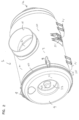
- the reference numeral 1, Fig. 1 generally designates an example air cleaner assembly according to the present disclosure.
- the air cleaner assembly 1 includes a housing 2 comprising a housing body 3 and an access cover 4. Access cover 4 is secured in place on the housing body 3 by a connection arrangement 7.
- the connection arrangement 7 comprises a plurality of latches 8.
- the housing body 3 includes a side wall 10 having a first open end 10a, over which access cover 4 is mounted. Opposite the first end 10a, the housing side wall includes a second end 10b. The second end 10b includes a housing end wall 11 thereon, having air flow aperture or port 12 therethrough. End wall 11 is typically not removable from side wall 10, and in some instances it is formed integral with wall 10.
- access cover 4 and housing body 3 comprise glass filled polypropylene molded to the selected configuration.
- the access cover 4 is mounted in such a manner that when connection arrangement 7 (i.e., latches 8) is released, access cover 4 can either be removed from housing body 3, or be moved to a position allowing access to an interior of the housing body 3 through end 10a.
- connection arrangement 7 i.e., latches 8
- access cover 4 is removably mounted to housing body 3, by latches 8.
- the air cleaner assembly 1 further includes an air flow port or aperture 15 providing air flow communication with an interior of the housing 2.
- air flow aperture 15 is an air flow inlet in side wall 10; and, air flow aperture port 12 is an air flow outlet, although alternatives are possible.
- the housing body 3 includes a mounting arrangement 20 thereon, by which the air cleaner 1 can be secured to the equipment on which it will be installed during use, for example a vehicle frame or equipment frame.
- the particular mounting arrangement 20 depicted comprises a plurality of mounting pads 21.
- Mounting pads 21 can be located at various places on a housing body 2, for convenient securement to a frame or other portion of the equipment with which the air cleaner assembly 1 is to be used. It is noted that the pads 21 can be positioned at a variety of locations, such that not all are used; which ones being used being dependent on the particular equipment configuration. Thus, housing body 2 may include some mounting pads 21 that are not actually used, in a selected mounting.
- AA 607 mm
- AB 346.1 mm
- AC 174.5 mm
- AD 366.6 mm
- AE 102 mm.
- principles of the present disclosure can be applied in a variety of sizes of units, the dimensions provided merely indicating the example.
- the air cleaner assembly 1 is depicted in perspective view, the view being directed toward access cover 4 and inlet aperture 15.
- the housing 2 e.g., side wall 10
- the housing 2 can be provided with mounting pads 21 at a variety of locations, allowing for variability in the type of equipment to which the air cleaner 1 can be secured, when installed, or orientation of installation.
- the air cleaner assembly 1 depicted includes an evacuator valve arrangement 25 thereon.
- the evacuator valve arrangement 25 comprises a diaphragm or other valve member through which water and/or preseparated dust can be ejected from an interior 2i of housing 2, during use.
- access cover 4 includes a peripheral rim 30 and end surface 31.
- the end surface 31 includes a central recess 32 with an outwardly directed central projection 33 therein.
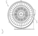
- FIG. 3 an end elevational view of the air cleaner 1 is depicted; the view of Fig. 3 being taken toward access cover 4. Normally, when the air cleaner 1 is installed, the evacuator valve 25 is directed downwardly. Thus, the end view of Fig. 3 is generally in the orientation of typical installation.
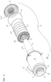
- FIG. 4 Attention is now directed to Fig. 4 , in which air cleaner assembly 1 is depicted in exploded view. Viewable in Fig. 1 are interiorly received components of the air cleaner assembly 1. In particular, primary filter cartridge 40 is viewable. Optional safety filter 41 is also shown. Finally, O-ring 42, which is positioned between access cover 4 and housing body 3, when air cleaner assembly 1 is assembled, is shown.
- the housing 2 defines a housing interior 2i in which the main or primary air filter cartridge 40 is received.
- the air enters the interior 2i through inlet 15, and is directed into an air flow annulus 45 surrounding the air filter cartridge 40.
- the air is directed through the air filter cartridge 40, in an out-to-in flow pattern, during filtering.
- the cartridge 40 generally includes a media pack 50 having air filtration media 51 therein. Upon passage through the media pack 50, the air is filtered. The filtered air passes into an internal cartridge support 55 and then outwardly through outlet 12.
- the internal cartridge support 55 is surrounded by media 41a of an optional safety filter 41, in some applications. In such applications, as the air passes into cartridge support 55, it passes through media 41a of the safety filter 41.
- the safety filter 41 can be left off in those applications in which a safety or secondary filter is not desired.
- the inlet port 15 is surrounded by structure 15a (and the outlet port 12 is surrounded by structure 12a) to which duct work or other flow passageway equipment can be attached, for use.
- FIG. 5 the air cleaner assembly 1 is depicted without latches 8 mounted thereon, for convenience.
- the main cartridge 40 is a service component, i.e., it is removable and replaceable within interior 2i without damage to either the cartridge 40 or the housing 2.
- Service access to interior 2i is provided by opening access cover 4. Typically this is conducted by removing access 4 from end 10a of side wall 10.
- cartridge 40 is a service component, it needs to be removably sealed in the air cleaner housing 2, to avoid flow into outlet 12 of unfiltered air.
- the filter cartridge 40 is provided with a housing seal arrangement 65, for this.
- media pack 50 includes opposite ends 50a, 50b. End 50a is secured to end cap 66.
- end cap 66 is a molded-in-place end cap 66a. By this it is meant that the end cap 66 is molded onto the media pack 50.
- a typical material useable for molded in place end caps is a foamed polyurethane such as described in US 6, 955, 701 ; US 2007/009040 ; and US 7, 070, 642 .
- End cap 66 is an open end cap, i.e., it includes a central opening 68 therethrough. Central opening 68 fits over support structure 55, during installation of cartridge 40 into air cleaner body 3. End cap 66 includes seal projection 70 thereon. The seal projection 70 is sized and shaped to be received within a receiver pocket 75 in the housing body 3, to form a housing seal therewith. Thus, projection 70 defines the housing seal or seal member 65, for the example shown. Further example shown, seal projection 70 is molded integral with a remainder of end cap 66.
- seal support member 70a is embedded within seal projection 70.
- Seal support member 70a is a rigid structural member which, by being embedded within seal projection 70, provides support to a radially outwardly directed seal formed by seal projection 70.
- Seal support 70a can comprise structure integral with inner liner 71 of cartridge 40; or, it can be a separate member embedded within projection 70.
- End 50b of media pack 50 includes second end cap 80 thereon.
- the second end cap 80 is a closed end cap; meaning it has no central apertures therethrough.
- the example end cap 80 depicted is not molded-in-place, but rather comprises a preform 81 first formed (typically by molding) and then secured to the end 50b of media pack 50; for example with a potting adhesive.
- An example material for end cap 80 is a molded ABS potted with a hard polyurethane.
- the second end cap 80 can comprise a composite including a preform member secured in place with an overmold, to end 10b of the media pack 50.
- the cleaner assembly 1 is depicted including optional safety cartridge 41 having an end cap, end piece or ring 91 and safety filter media 41a.
- Safety filter media 41a is embedded in the end ring 91.
- the end ring 91 includes an open central aperture 92 by which it can fit around a portion of cartridge support 55.
- the safety filter media 41a is positioned between the main cartridge 50 and interior 55i of cartridge support 55. Thus, to reach interior 55i of support 55 and be directed outwardly through outlet 12, the filtered air from cartridge 50 passes through safety media 41a.
- the cartridge support 55 has a side frame 55s which extends from a base region 55b (adjacent housing end 11) to an opposite outer end 55v (adjacent housing sidewall end 10a).
- the side frame 55s generally includes flow apertures 55f therethrough.
- the particular example support 55 depicted comprises a side frame 55s which includes a grid of longitudinal extensions 551 and radial, hoop, cross-extensions 55c.
- the side wall 55s extends with a narrowing taper from base 55b to end 55t; i.e., side frame 55s has a generally conical shape in this region.
- the conical angle, c i.e., internal acute angle of slant, is typically at least 1°, usually at least 2° and often within the range of 2° to 10° inclusive.
- base 55b, of support 55 includes an imperforate region 55y in base 55b.
- the support 55 is molded integral with tube 95 that defines air flow aperture 12.
- the particular example housing body 3 depicted is a single (plastic) molded component comprising side wall 10, inlet 15, tube 95 and cartridge support 55.
- a central longitudinal axis for support 55 is indicated at X.
- FIG. 5A an enlarged fragmentary portion of Fig. 5 ; and, to Fig. 5B , a second enlarged fragmentary portion of Fig. 5 .
- housing 3 includes a tube 95 defining outlet 12. Surrounding tube 95, the housing body 3 defines a seal receiving pocket 96.
- the pocket 96 is formed between an outer surface portion 95o of tube 95 and an outer wall 97, with a pocket end closed by wall section 98 extending therebetween.
- Housing seal 70 of cartridge 5 is pushed into the pocket 96 to form a seal therewith.
- housing seal 70 is pressed radially outwardly against wall 97, by seal support 70, and/or wall 95o, to form an outwardly directed, peripheral, radial housing seal 65.
- ocket 96 corresponds to pocket 75, Fig. 5 .
- Alternate seals can be used on cartridges in accord with the present disclosure, including ones having an internal radial seal in general accord with US, 5,547,480 ; 6,652,614 ; WO 2007/022171 ; 6,039,778 ; and 6,955,701 .
- base section 55b of support 55 can be configured to accommodate an internally, radially, directed seal in general accord with these references.
- support 55 includes end member 55t.
- end member 55t be closed, i.e., closed against passage therethrough of air flow.
- end member 55t will be closed, so as to not provide for an air flow bypass route around media 41a of safety cartridge 41 (when used).
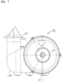
- FIG. 6 air cleaner 101 is depicted in exploded view.
- the air cleaner 101 includes housing 102 comprising housing body 103 and access cover 4.
- Cartridge 40 is positionable within housing body 103.
- Optional safety filter media 41 is viewable.
- O-ring 42 is also viewable.
- air cleaner assembly 101 differs from the specific configuration of the housing body 103 with respect to inlet 107.
- Inlet 107 in the housing body includes an inlet duct 108 attached thereto, with an end piece 109 and a rim 110.
- Air cleaner 1 is differently configured with respect to such features.
- air cleaner 101 including the replacement part features concerning the cartridge 40 can be the same.
- Each of the air cleaners 1, 101 can be configured to use the same access cover 4.
- FIG. 7 an end view of air cleaner assembly 101, taken toward access cover 4, is depicted.
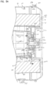
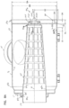
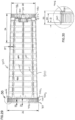
- FIG. 8A a cross-sectional view of housing body 3 (of air cleaner 2, Figs. 1-5 ) analogous to Fig. 5 , but pictured without: access cover 4; cartridge 40; and safety element 41. Also, relative to Fig. 1 , latches 8 are not shown on the housing body 3, of Fig. 8A . Further, in Fig. 8A , an evacuator valve 25 ( Fig. 1 ) is not positioned on body 3, of Fig. 8 ; however, evacuator aperture 25a, across which evacuator valve 25 would be positioned for use, is viewable.
- FIG. 8A is not through a center of center support 55, but rather slightly toward the viewer from center.
- Fig. 8B is an analogous cross section, but taken through a center of center support 55.
- housing body 3 viewable in Figs. 8A , 8B comprises a single, molded, structural piece. Of course it can be alternately constructed. In a typical application, housing body 3, including support 55, will be made as a single, integral, piece from a plastic.
- end member 55t is, again, opposite base 55b.
- End 55t projects in a direction away from outlet 12 toward open end 10a.
- a portion of end member 55t can project outwardly beyond end 10a of side wall 10, in a direction opposite end wall 11 and outlet 12; i.e., in a direction toward access cover 4, when installed.
- end member 55t includes two projection sections: first (perimeter ring) projection 125; and, second (central) projection member 126.
- first (perimeter ring) projection 125 projects axially away from adjacent portions of end member 55t in a direction away from housing end 11.
- axially in this context, it is meant that the projections are in the same general direction as longitudinal axis X.
- first (ring) projection 125 is separated from second (center) projection 126 by outer surface recess region 130 which extends around projection 126.
- second ring projection 125 is continuous and circumscribes (surrounds) center projection 126.
- End 55t member includes an outer surface 55x and an inner 55z.
- Recess 130 is in outer surface 55x.
- the projection is “axial” or extends “axially”, it is not meant that the projection is necessarily perfectly co-linear with central longitudinal axis X, but rather it is in the same general longitudinal direction.
- central projection 126 is conical in shape and would have a circular cross section in a plane perpendicular to axis X. More specifically, projection 126 has a conical side wall 126s, which tapers inwardly toward tip 126t. Tip 126t, however, is somewhat truncated, and does not necessarily come to either a sharp point or a completely flat end.
- DA 332.6 mm
- DB 322.4 mm
- DE 174.5 mm
- DF 1.5 mm radius
- DG 63.8 mm
- DH 25.1 mm
- DJ 5 mm radius
- DK 3.2 mm
- DL 29.2 mm
- DI 25.3 mm.
- FIG. 8B a second cross-sectional view analogous to Fig. 8A is depicted, but in this instance taken through a center line of projection 126.
- projection 126 can be seen defined by hollow interior 126i projecting axially away from end 11.
- projection ring 125 can also be seen as having a hollow interior 125i also projecting axially away from end 11.
- cartridge support end 55t has an outer surface 55x and inner surface 55z.
- the example cartridge support end 55t is contoured on both surfaces 55x, 55z.
- An example shape is such that there is a central (in the example shown conical) projection 126 spaced from a ring projection 125 by a recess 130, in the outer surface 55x.
- the inner surface 55z is defmed with a central (for the example shown conical) outer projection recess 126i spaced from the recessed ring 125i by surface 131i, leaving the observation that surface 131i generally projects toward end wall 11 and recesses 125i, 126i project away from end wall 11.
- Projection 125 includes an outer perimeter surface 125c, Fig. 8B .
- perimeter surface 125c is a smooth, non-contoured surface defining a circular perimeter, and thus has a generally cylindrical shape.
- the cylinder surface 125c may taper inwardly slightly in extension away from end wall 11 in some applications.
- End member 55t includes a peripheral shoulder 55p projecting radially outwardly from a base end of surface 125c.
- Surface 125c is defined to project through aperture 92 at end cap 91 of a safety element 41, Fig. 5 , when used. Shoulder 55p is sized and positioned to receive end cap 91 abutting thereagainst, when the optional safety element 41 is installed.
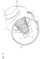
- FIG. 9 a perspective view of housing body 3 ( Figs. 8A , 8B ) is provided; Fig. 9 being taken toward open end 10a.
- central cartridge support 55 is viewable.
- end member 55t of support 55 can be seen.
- Central projection 126 is viewable, surrounded by recess 130.
- Outer projection 125 is also viewable, including outer circular wall 125c and an opposite inner wall 125x.
- Central projection 126, recessed surface 130 and ring projection 125 collectively define receiver recess 130x in outer surface 55x of end 55t.
- Receiver recess 130x is positioned to receive projecting therein a corresponding projection member on a primary filter cartridge 40 during installation, as discussed below.
- outer surface 55x, of end member 55t defines the first member of a first projection/receiver arrangement providing for engagement between the cartridge 5 and the central cartridge support 55.
- projections 125, 126 project into receiver sections of a corresponding primary filter cartridge 40; and, a portion of a primary filter cartridge 40 projects into receiver 130x on support 55.
- the inner wall 125x of ring projection 125 can be seen to have a serpentine surface shape with alternating outwardly curved, concave, sections 134 and inwardly projecting convex portions 135.
- swipe when used to refer to the definition of a surface or wall, it is meant to refer to a surface that does not define a circular definition, but rather includes alternating convex and concave sections therein.
- serpentine wall surface 125x eight (8) concave sections 134 are separated by eight (8) convex portions 135, in extension of wall 125x around center projection 126.
- each concave section 134 is the same shape and size as the other concave sections; and, each convex portion 135 is the same shape and size as the other convex portions.
- an eight (8) petal arrangement is defined by wall 125x.
- serpentine wall surface 125x depicted, and the petal arrangement has 8-fold rotational symmetry, i.e., each petal is the same size and shape as each other petal, and the petals are evenly, radially, spaced.
- 8-fold rotational symmetry is used to refer to a shape definition which can be rotated around a central axis with eight evenly radially, spaced positions, in which it can align with itself.
- an octagon has 8-fold rotational symmetry
- a square has 4-fold rotational symmetry.
- serpentine surface 125X comprises alternating convex and concave sections, usually at least three concave sections and typically at least five concave sections and usually 6-10 concave sections.
- FIG. 10 Attention is now directed to Fig. 10 .
- cartridge 40 is shown separate from air cleaner assembly 1.
- Fig. 10 a portion of cartridge 40 is shown in cross-section, facilitating understanding of internal detail.
- cartridge 40 comprises media pack 50.
- the media pack 50 includes air filtration media 51.
- a variety of types of media can be used for the cartridge 40.
- the particular example media 51 depicted comprises pleated media, with inner pleat tips 51p and outer pleat tips 51o.
- the media 51 extends between first and second opposite media ends 51a, 51b.
- the pleated media 51 can be selected from a variety of filtered media of which are used for air filtration.
- the particular efficiency, physical and operational perimeters for the media 51 are a matter of choice for the application intended.
- known filtration media can be used.
- the media pack 50 defines an outer perimeter 50o and an inner perimeter 50i.
- the outer perimeter 50o is defined by outer pleat tips 51o. Extending around the outer pleat tips 51o in a helical pattern, is adhesive bead 140, which helps maintain pleat spacing and provides pleat support.
- the media pack 50 further includes an inner liner 141, corresponding to liner 71, Fig. 5 .
- the inner liner 141 is a support liner for the media 51, along inner pleat tips 51p.
- the inner liner 141 is porous and can comprise a plastic or metal structure.
- the inner liner 141 is a plastic structure comprising a plurality of longitudinal or axial strips 141x and cross or radial hoops or strips 141c.
- the media pack 51 can include an outer liner, for example a plastic or metal liner.
- media pack 50 (i.e., media 51 and liner 41) is embedded in end cap 66.
- End cap 66 again, is typically a molded-in-place end cap 66a, including, molded integral therewith, housing seal member 65, which, in the example shown, comprises projection 70. Seal support 70a, again, is embedded in projection 70.
- the housing seal member 70 includes an outer (peripheral) seal surface 70o configured with a stepped or tapered section 70t to facilitate insertion into pocket 96 with compression against wall 97, Fig. 8A , during installation, see Fig. 5B .
- end cap 80 in the example depicted comprising pre-form 81.
- preform in this context, it is meant that the example end cap 80 is formed (for example from a molded plastic) and then media pack 50 is potted thereto, for example with adhesive.
- a typical material is molded ABS potted with hard polyurethane.
- the example end cap 80 includes outer peripheral rim 150, outer end ring section 151 and central recess section 152.
- media pack 50 is potted to end cap 80 by being positioned to project into recess 155 formed between outer peripheral rim 150 and central recess section 152.
- Rib 156 is a circular standoff rib for the media pack 50, during potting.
- recess 155 is generally positioned on an opposite side of end cap 80 from ring 151.
- the outer pleat tips 51o form a generally conical shape, tapering downwardly in extension from media end 51a toward media end 51b.
- Principles described herein can be implemented in a variety of shapes of arrangements including cylindrical ones and conical ones. When a conical shape is used, typically the angle of taper will be at least 0.5°, typically at least 1° and often within the range of 1-4°.
- the conical taper for the media pack 51 has a smaller angle of taper, than the conical taper to support 55, Fig. 5 , as shown.
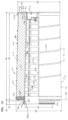
- FIG. 11 an enlarged cross sectional view of the end cap 80 depicted in Fig. 10 .
- the cross sectional view is of the end cap 80 only, as it would be viewed before being secured to the media pack 50, Fig. 10 .
- central recess portion 152 includes the following features: outer peripheral wall 160 and end wall 161.
- the outer wall 160 generally projects into interior 60 of the media pack 50, of Fig. 10 .
- Adjacent or slightly spaced from media pack interior 50i, inner wall 161 generally extends across the interior 60.
- End wall 161 includes inner surface 161y and outer surface 161x.
- the inner surface 161y is generally directed toward end cap 66 in cartridge 40.
- Surface 161x is generally opposite surface 161y, and is directed away from end cap 66.
- inner, surface 161y includes outer ring section 162. Radially inwardly from ring section 162 is provided circular, axially outwardly projecting receiving pocket or ring recess or receiver 165 defined by outer wall section 166, inner wall section 167 and end wall section 168.
- ring receiver 165 generally projects in a direction opposite end cap 66, Fig. 8A .
- Ring recess 165 is sized and shaped to receive, projecting therein, ring projection 125 on the central cartridge support end 55t, during installation. Ring recess 165 is typically continuous in extension around central axis X. Referring to Fig. 16 , it is noted that central section 4c is not necessarily centered on a center point for perimeter 4p, but rather is depicted as eccentrically positioned.
- Wall section 167 typically has an surface 167i in side 161y which has a serpentine shape of alternating outwardly directed convex and outwardly directed concave (or inwardly directed convex) sections, which engage wall 125x, Fig. 9 . That is, serpentine surface 125x, Fig. 9 , pushes around and engages serpentine surface 167i, Fig. 11 , in surface-to-surface engagement. As a result of the petal structure on surface 125x receiving outwardly projected petals on serpentine wall 167i, when engagement occurs, end cap 80, and thus cartridge 40, will not readily rotate relative to central cartridge support 55.
- surface 161y Spaced radially inwardly of wall 167, surface 161y includes a central outer projection 170.
- the central outer projection 170 includes an outer end section 171 and side wall 173.
- the side wall 173 is generally conical and surrounds central axis x.
- central outer projection 170 is sized to receive projecting therein, central projection 126 on end 55t of central cartridge support 55, when the cartridge 40 is installed in the housing 2.
- Central projection 170 further includes base section 175 with internal surface 176.
- base section 125 projects into recess 130x, Fig. 9 , during installation.
- Outer surface 161x includes, defined therein, receiver groove 180, between walls 167, 175.
- Outer surface 167o and outer surface 175o of surfaces 167, 175 respectively, are generally each serpentine, forming a serpentine receiving groove 180 having an outer serpentine surface along wall 167o defined by alternating outwardly projecting concave and inwardly projecting convex sections; and, an inner surface along wall 175o defined by outwardly projecting convex and inwardly projecting concave sections.
- outwardly projecting concave sections of walls 167 are aligned radially with outwardly projecting convex sections of wall 175; and, inwardly projecting convex sections of wall 167 are aligned radially with inwardly projecting concave sections of wall 175, to form a serpentine receiver groove 180.
- Groove 180 is a receiver groove for a projection on access cover 4, as discussed below.
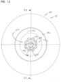
- the receiver groove 180 has a dimension such that a smallest internal dimension across a space omregion surrounded by the receiver groove, as measured for example at XX, Fig. 12 , is at least 10 mm, typically at least 15 mm and often at least 20 mm; for example, the example typically being with in the range of 20-40 mm, inclusive.
- FIG. 12 a schematic, outer, plan view of pre-form 81, in particular directed towards surface 161x.
- Central groove 180 is viewable. It is noted that in Fig. 12 , groove 180 is depicted in a simplified, schematic, view. Surfaces of walls 167o, 175o can be seen from Fig. 11 , to taper away from one another, from tip 180t of groove 180 outwardly. Contour lines to depict this are not shown in Fig. 12 .
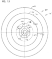
- Fig. 13 an inside end view of end cap 80 is depicted, i.e., toward surface 161y.
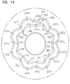
- FIG. 14 an enlarged, fragmentary, view of a portion of Fig. 12 .
- Groove 180 can be viewed between walls 167o and 175o.
- Wall 167o can be seen to define a serpentine surface, with outwardly directed concave sections 167x with inwardly projecting convex sections 167y.
- the inner surface 175o can be seen define a serpentine wall with outwardly projecting convex sections 175x and inwardly projecting concave sections 175y.
- concave sections 167x are aligned with convex sections 175x; and concave sections 175y are aligned with convex sections 167y.
- the result is a serpentine groove 180.
- groove 180 is sized and shaped such that a continuous circular projection will not project into groove 180, but rather such that a continuous projection extending into groove 180 would preferably have a serpentine shape.
- FIG. 15 an enlarged, fragmentary, view of portion surface 161y is provided.
- Inner surface 167i comprising convex sections 167e and concave sections 167f is viewable. This surface 167i is configured to engage surface 125x on support 55, as discussed previously.
- Fig. 16 is an outer plan view of access cover 4. That is, the view of Fig. 16 is generally in the direction of arrow 4x, Fig. 1 .
- Access cover 4 includes a peripheral rim 4p and outer end surface 4b with central section 4c.
- access cover 4 is shown in cross-sectional view, taken generally along line 17-17, Fig. 16 .
- Access cover 4 includes interior surface 4y, which faces in interior of housing 2; and, exterior 4z, which is opposite.
- access cover 4 includes perimeter rim section 200.
- Perimeter rim section 200 is sized and positioned to engage sidewall 10, during installation, Fig. 5 .
- inner surface 4y comprises a surface which engages cartridge 40, during installation.
- Inner surface 4y includes outer ring section 201, which overlaps an end 50b of the media pack 50 during installation, of Fig. 5 .
- radially inwardly from region 201 is inwardly projecting wall 202.
- Inwardly projecting wall 202 generally projects into interior 60 of cartridge 40, during installation.
- wall 202 is generally surrounded by end 50b of media pack 50, during installation.
- projection 210 Radially inwardly from wall 202, and on surface 4y, is provided projection 210.
- Projection 210 is sized and shaped to project within receiving groove 180, Fig. 11 , during installation.
- the projection 210 is typically continuous in extension around axis X, although alternatives are possible.
- projection 210 is typically solid (non-hollow) and typically includes no apertures therethrough.
- the projection 210 has a radial outer surface 211 and a radial inward surface 212.
- the outer surface 211 is generally serpentine, comprising alternating outwardly convex and inwardly concave sections; and, inner wall 212 is generally serpentine having corresponding inwardly projecting convex and outwardly projecting concave regions, which alternate with respect to one another.
- Outwardly projecting convex sections of wall 211 are aligned radially with inwardly projecting concave sections of wall 212; and, inwardly projecting concave sections of wall 211 are radially aligned with inwardly projecting convex sections of wall 212.
- the wall 210 is sized and shaped to be received within serpentine receiving groove 180, Fig. 11 .
- the dimension across projection 210, between opposite portions of inner surface 212 is at least 10 mm, usually at least 15 mm often at least 20 mm, for example 20-40 mm inclusive. This dimension would correspond to dimension XXX, Fig. 17 .
- wall 210 surrounds central outer projection 220, which forms projection 33, Fig. 2 .
- Central outer projection 220 in surface 4y, generally extends away from wall 11, Fig. 5 , and defines a receiving space 221 for projection 170, Fig. 11 .
- a fragmentary plan view is provided of a portion of internal surface 4y.
- Projection 210 is viewable, as well as surfaces 211, 212. It is noted that surfaces 211, 212 generally converge toward one another in extension to tip 210t, Fig. 17 ; and diverge away from one another in extension therefrom.
- reinforcing ribs 230 are viewable on surface 4y.
- FIG. 19 an enlarged, schematic, view of wall 210 is provided, to facilitate an understanding of the contouring or serpentine shape to surfaces 211, 212.
- outer surface 211 of projection 210 can be seen to comprise a serpentine shape with alternating contours comprising inwardly directed concave sections 211x and outwardly projecting convex sections 211y.
- Surface 212 can also be seen to be serpentine, having outwardly projecting concave sections 212y and inwardly projecting convex sections 212x.
- Each section 212x is aligned radially with a section 211x
- each section 212y is aligned radially with a section 211y.
- wall 210 has an 8 petal shape, with 8-fold radial symmetry around center 215.
- central cartridge support 55 in housing body 3
- main filter cartridge 40 in housing body 3
- access cover 4 advantageous interaction among central cartridge support 55 (in housing body 3); main filter cartridge 40; and, the access cover 4 can be understood.
- the features are as follows.
- the cartridge 40 is positioned with an anti-rotational interaction with the support 55.
- This anti-rotational was depicted in Fig. 5A , and results from structure on outer surface 55x of end 55t ( Fig. 8A ) engaging structure on inner surface 161y of end cap 80.
- the anti-rotational interaction results from serpentine wall 125x of ring projection 125 extending around and engaging outwardly directed serpentine wall 167i, in surface 161y of end cap 80.
- serpentine engagement cartridge 40 could readily be positioned in one of a plurality of selected rotational orientations relative to the central cartridge support 55, when the cartridge 40 is installed.
- the anti-rotational engagement between the cartridge 40 and the support 55 ensures that the cartridge 40 is secured in only one of certain pre-selected orientations for engagement with the access cover 4.
- Access cover 4 includes projection 210 which extends into a groove 180 defined in outer surface 161x end piece or cap 80. Projection of the projection 210 into the groove 180 provides that the access cover 4 supports cartridge 40 against undesirable levels of cantilevered motion of end 50b, i.e., the adjacent end piece 80. That is, the cartridge end 50b will not undesirably move, Fig. 5A , in either an up-down or in-out motion (or mix thereof) relative to the viewer. The amount of motion allowed, will depend upon the relative thickness of the projection 210 and the width of the groove 180. Typically they are selected to allow only minimal motion, i.e., that amount of clearance which allows for ease of assembly.
- the cartridge 40 is supported at media pack end 50b against undesirable levels of cantilevered motion, without any portion of the access cover 4, other than perimeter region 30 and projection 200 surrounding the media pack end 50b, i.e., with no portion surrounding the media pack 50b that also engages cartridge 40, i.e., the media pack 50.
- the cartridge 40 is not supported at end 50b by support around the exterior of the cartridge 40, but rather only interiorally.
- the projection 210 extends into groove 180 a distance of at least 5 mm, usually at least 12 mm, and typically in the range of 15 to 30 mm.
- groove 180 has a width, along its depth of extension, of no greater than 10 mm, typically no greater than 9 mm and usually within the range of 4 to 7 mm.
- the groove 180 is at least 6 mm deep, usually at least 12 mm deep and typically within the range of 12-25 mm deep.
- radial outer wall 167o of groove 180 is positioned at least 20 mm, usually at least 30 mm, from the media pack 50.
- the thickness of projection 210, along its length is at least 1 mm, typically at least 1.5 mm and usually within the range of 1.5 to 4 mm.
- the projection/receiver arrangement comprising projection 210 and groove 180 will be convenient to protect cartridge 40 against cantilever motion.
- serpentine outer surface 211 of projection 210 will engage surface 167o on projection 167 in a manner inhibiting relative rotation between access cover 4 cartridge 40. Indeed, an overall anti-rotational arrangement is created by the sandwiching of wall 167 between surface 125x and surface 211.
- projection 33 in access cover 4 acts a receiver 33r for projection 170 in cartridge 40.
- Projection 170 on cartridge 40 acts, along an inside surface, as a receiver for projection 126, on support 55.
- projection 170 extends into receiver 33r a distance of at least 10 mm, usually within the range of 15 mm to 50 mm, inclusive; and, projection 126 extends into receiver 170 a distance of at least 10 mm and usually 15 to 50 mm, inclusive.
- receiver groove 168 formed between walls 167, 166, Fig. 11 is at least 10 mm wide, usually at least 20 mm wide, and often within the range of 20-30 mm, inclusive, wide. It is typically not more than 40 mm wide.
- the access cover 4 will typically not readily be installed in the housing side wall 10, unless the cartridge 40 is properly sealed in position.
- End piece 91 has an internal aperture 92 which fits over wall 125c of ring projection 125.
- the cartridge end piece 80 includes a ring projection directed inwardly, identified at 240.
- the ring projection 240 engages end 91e of end piece 91 to inhibit safety element 41 from moving toward access cover 4, once installed.
- Safety element 41 does not include, in the example shown, an end cap at an opposite end from end 91. Rather, being conically shaped in the example shown, the media 41 is pushed over conical support 55 until a snug engagement is obtained.
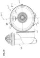
- the air cleaner assembly 301 includes housing 302 comprising a housing body of 303 and access cover 304.
- the access cover of 304 is secured in place on the housing body 303 by a connection arrangement 307 comprising latches 308.
- the housing body includes a side wall 310 having a first open end in 310a over which access cover 304 is mounted.
- the housing side wall includes a second end 310b having a housing end wall 311 thereon, with air flow aperture 312 therethrough.
- the air cleaner 301 includes an air inlet aperture arrangement 315 receiving air from inlet assembly 316.
- the assembly includes mounting pads 321 and evacuator valve arrangement 325.
- the assembly, 301 includes a cartridge support 355 and safety cartridge 341.
- air cleaner body and access cover 303, 304 can be the same for air cleaner assembly 301 as for assembly 301, Fig. 6 , or assembly 1, Fig. 1 , depending on the specific application of principles.
- cartridge 340 is depicted mounted within interior 302i of housing 302.
- Cartridge 340 can be the same as cartridge 40, Fig. 5 except modified as described.
- end cap 366, Fig. 21 is modified from end cap 66, Fig. 5
- end cap 367 is modified from end cap 80.
- end cap 366 is molded in place and includes seal projection 370 thereon molded integral therewith. Seal projection 370 engages, and seals against wall 397, of pocket 396.
- seal support member 410 embedded within projection 370. Projection 410 is discussed further below, in connection Figs. 29-31 .
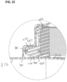
- FIG. 23 housing body 303 is depicted. It can be seen that support 355 and support end 355t can be generally analogous to analogous features described previously, in connection with embodiment of Figs. 1-5 .
- end 355t includes ring projection 425 and central projection 426.
- FIG. 24 an enlarged, fragmentary, portion of Fig. 23 , is indicated.
- pocket 396 with opposite walls 397 and 395 is viewable.
- FIG. 25 an end view of housing body 303 is shown, with access cover 304 removed.
- FIG. 26 cross-sectional view of cartridge 340 is depicted.
- the cartridge 340 comprises a media pack 350 including media 351 surrounding an inner liner 352 to define open interior 360.
- the inner liner 352 extends between end cap 366 and 367.
- end caps 366 and 367 are both molded into place, each typically comprising molded foamed, compressible, polyurethane.
- Liner 352 is embedded in and extends between the end caps 366 and 367.
- Seal projection 370 is integral and molded as part of end cap 366.
- Fig. 27 is a enlarged, fragmentary view of a potion of Fig. 26 .
- projection 370 molded integral with a remainder of end cap 366, is viewable.
- Further projection 410, embedded in projection 370 can be seen.
- Projection 410 is part of liner 352 and will provide support to seal member 370 along sealing surface 370s during installation of the cartridge 340 into the housing 302.
- Access cover 304 can be seen to include a projection 410 with a serpentine outer surface 411 and a serpentine inner surface 412. Access cover 304 can be identical to access cover 4, Fig. 17 .
- Liner 352 can be seen to include media support section 450 extending between ends 451 and 452.
- Media support section 450 comprises longitudinal strips 455 and cross strips 456 defining apertures 457 for air flow.
- support 450 includes a seal support region 410 integral with the remainder of 450.
- the seal support region 410 comprises a region of larger diameter than immediate adjacent portion 450a of support 450.
- outwardly extending shoulder 410b is adjacent to region 410 between region 410 and media support section 450.
- Region 410 includes a plurality of apertures 410a therethrough.
- shoulder 410b will provide a media stop to the media 351, when positioned around media support 450. That is, shoulder 410b will extend across an end of the media 351, during assembly, for convenient support of the media 351.
- an extension 470 which will be embedded within end cap 367 is shown. Extending across end 452, and surrounded by support 470, is provided an end piece 490 with a configuration analogous to central portions of end cap 151, Fig. 11 . Thus, serpentine receiving groove 500 and central projection receiver 401 are present.
- end cap 367 comprises a composite end cap including a molded-in-place outer ring portion, Fig. 27 , and a central portion 481 comprising preformed material having an appropriate configuration for the anti-cantilevered and anti-rotational support; in this example the central portion 481 being integral with liner 352.
- FIG. 30 an enlarged, fragmentary view of a portion of Fig. 29 is shown.
- Fig. 31 a perspective view of support 352 is shown.
- air cleaner assemblies and components are described and shown in detail. There is no specific requirement that an air cleaner assembly or component include all of the features characterized described herein, in order to obtain some benefit under the principles of the present disclosure.
- an air cleaner assembly includes a housing and a serviceable primary filter cartridge positionable within the housing and removable therefrom, without damage to the housing or the serviceable filter cartridge.
- An optional safety element is also provided.
- the housing generally includes a housing body and an access cover.
- the housing body includes a sidewall and a central cartridge support.
- the sidewall generally defines a housing body interior.
- the housing body typically includes an end wall with an air flow aperture therethrough, and an open end opposite the end wall.
- the central support extends from a support base surrounding the air flow aperture in a direction toward the housing open end.
- the housing end wall and the open end are at opposite ends of the housing side wall.
- the housing includes an air inlet arrangement.
- the inlet arrangement is an air inlet flow aperture in a side wall of the housing body.
- the flow aperture in the side wall is an inlet flow aperture
- the air flow aperture in the end wall is an outlet aperture, for out-to-in flow with respect to a receive filter cartridge, during use. It is noted, however, that many of the principles described herein can be used in association with in-to-out flow (opposite flow) if desired, in some applications.
- the central cartridge support includes a support end remote from the base.
- the support end remote from the base includes a first (ring) projection spaced from, a second (central) projection to define a receiving space therebetween.
- the first projection is an outer ring projection that extends around, (in the example shown continuously) the second projection (which is a central projection).
- Each of the first ring projection and the second central projection generally project in a direction away from support base and the end wall.
- the ring projection extends at least 5 mm, usually 7 mm, and often an amount within the range of 7 to 25 mm, inclusive, from immediately adjacent portions of the support end; and the central projection extends at least 10 mm, usually 15 mm, and often an amount within the range of 18 to 40 mm, inclusive, from immediately adjacent portions of the support end.
- the second, central, projection projects outwardly from the open end of the side wall.
- the serviceable primary air filter cartridge is positioned within the housing body interior.
- the air filter cartridge comprises a media pack surrounding an open filter interior and extending between first and second end caps.
- the first end cap is an open end cap with a central aperture therethrough.
- the cartridge is positioned with the central cartridge support on the housing projecting through the open central aperture of the first end cap and into the open filter interior.
- a housing seal is positioned at the first end cap.
- the housing seal is molded integral to the first end cap, for example from foamed polyurethane, although alternatives are possible.
- the housing seal can be configured, for example, as a radial seal, either inwardly or outwardly directed.
- the housing seal is a projection extending axially away from the remainder of the first end cap, in a direction away from the media pack; and, the housing seal includes a radially outwardly directed radial seal surface.
- an embedded support is provided in the housing seal.
- the embedded support can comprise a portion of an inner liner. In some instances it can also form an end stop for the media. Alternate housing seal arrangements are possible.
- the second end cap is a closed end cap including an inner surface with a central receiver projecting away from the first end cap.
- the central receiver projecting away from the first end cap, in the second end cap, receives the central projection of the cartridge support projecting therein, when the cartridge is installed.
- the inner surface of the second end cap also typically includes a first ring receiver which surrounds, and is spaced from, the central receiver.
- the first ring receiver in the second end cap is configured to receive, projecting therein, the ring projection of the housing central cartridge support, when the cartridge is installed in the housing.
- an inwardly projecting wall or section of the first end cap separates the ring receiver and the central receiver.
- the second end cap of a depicted embodiment includes an outer surface with a receiving groove therein.
- the receiving groove is positioned opposite the inwardly projecting section of the inner surface located between the ring receiver and the central receiver; i.e., the receiving groove is formed on the outer surface of the end cap by structure surrounding the central receiver in the inner surface.
- the serviceable primary air filter cartridge is positioned in the housing body interior with: the housing seal of the primary air filter cartridge sealed to a portion of the housing body; the central cartridge support projecting through the first end cap open aperture and into the open filter interior; and, with the central projection on the support end of the housing body support projecting into the central receiver on the second end cap.
- a first ring projection on the support end of the central cartridge support also projects into the ring receiver on the second end cap.
- the access cover is secured over the open end of the housing body.
- the access cover includes an inside surface with a first ring projection.
- the access cover is positioned with the first ring projection on the inside surface projecting into the receiving groove on the outer surface of the second end cap of the primary filter cartridge.
- the first end cap is a molded-in-place end cap, for example from polyurethane foam.
- the second end cap is typically either a pre-formed end cap, for example from metal or plastic, to which the media pack is secured by an adhesive or potting arrangement; or; a composite end cap comprising a central preform section secured to the media pack by a molded-in-place ring.
- the central preform section can comprise a portion of a cartridge media support liner.
- the housing seal on the first end cap is typically formed integral with the end cap, and may comprise a radially directed seal. Either outwardly directed or inwardly directed radial seals are possible.
- housing seal arrangement which includes a seal projection integral with the remainder of the end cap.
- the seal projection includes embedded therein, a seal support.
- Seal support can comprise of portion integral with media inner liner.
- the support embedded within the seal projection is not only integral with a media inner liner, but defines a support shoulder or end stop for an end of the media, embedded in the end cap.
- the outer surface of the second cap of the primary filter cartridge includes a central outward projection thereon.
- This central outward projection defines, on an inside surface thereof, a central outwardly projecting receiver.
- the access cover includes an inner surface with an outwardly projecting receiver.
- the outwardly projecting receiver on the inside surface of the access cover receives, projecting therein, the central outward projection of the second end cap of the primary air filter cartridge.
- the air cleaner assembly includes serviceable safety or secondary filter having a first end cap and an extension of media secured to the first end cap.
- the first end cap includes a central aperture therethrough.
- the secondary filter is positioned within the open filter interior of the primary air filter cartridge, with the media of the secondary filter surrounding positioned against the central cartridge support.
- the central aperture of the second air filter first end cap is sized and positioned around a portion of the support end of the central support, with ring projection of the central support projecting therethrough.
- the first ring projection on the access cover inner surface has a serpentine inner wall surface and a serpentine outer wall surface.
- the receiving groove on the outer surface of the primary filter cartridge second end has at least one wall (either inner and outer) which is serpentine, and typically both walls are serpentine.
- the first ring projection in the access cover can be non-rotatably engaged in the receiving groove on the outer surface of the primary filter cartridge second end cap.
- non-rotatably engaged in this context, it is meant that the primary filter cartridge and access cover cannot be rotated dependently of one another, while engaged.
- the cartridge can be supported against cantilevered motion at the closed end cap, relative to the remainder of the housing.
- This anti-cantilevered motion support is facilitated also by engagement between the primary filter cartridge and the cartridge support.
- the remote (outer) end of the central support can be provided with the first ring projection which has an inwardly directed serpentine surface; and, the filter cartridge end cap can include a ring receiver with radially outwardly directed serpentine surface. These two serpentine surfaces can be engaged to provide for a non-rotatable engagement between the primary filter cartridge and the cartridge support. This can be used to help position the cartridge when installed over the cartridge support in an appropriate orientation radially, for receiving the projection of the access cover, when the access cover is installed during completion of a service operation.
- the conical support includes a conical side wall section narrowing in diameter in extension toward the support end from a base region adjacent the housing end wall.
- the conical side wall section typically has a conical taper of at least 1°.
- the central support can include a porous the wall portion and an imperforate base portion; the base portion being adjacent the housing body end wall.
- the media pack of the primary end filter cartridge can have a conical side wall section tapered downwardly in extension from the first end cap toward the second end cap.
- the conical side wall section of the primary filter cartridge media pack typically has a conical angle of at least 0.5°.
- the media pack of the primary filter cartridge has a conical side wall section of a second conical angle
- the first conical angle can be provided greater than the second conical angle.
- the central support tapers downwardly at a sharper angle than does the media pack.
- componentry useable with air filter assemblies is provided. Included among the componentry is an air filter cartridge useable as a primary filter cartridge in an air cleaner assembly.
- the cartridge typically includes a media pack surrounding an open filter interior and having first and second ends.
- the first end cap is positioned in the media pack first end and includes a central aperture therein.
- a housing seal member is typically positioned on the first end cap and can be formed integrally with the first end cap.
- the seal member can include a seal support embedded therein, as described.
- a second end cap is positioned on the media pack second end.
- the second end cap includes an inner surface and an outer surface.
- the second end cap can be provided as a perform, in some applications.
- the outer surface of the second end cap includes a receiving groove therein.
- the receiving groove is at least 6 mm deep.
- the receiving groove is formed between inner and outer radial walls, and is typically configured as a continuous ring.
- the outer wall receiving groove is typically spaced radially inwardly at least 20 mm from the media pack.
- Inner surface of the second end cap includes a central receiver projecting outwardly away from the first end cap.
- the central receiver is surrounded by the receiving groove.
- the receiving groove in the outer surface of the second end cap is defined between walls spaced no more than 25 mm apart, and typically no more than 10 mm apart.
- the receiving groove in the outer surface of the second end cap is a serpentine receiving groove. It is formed by inner and outer walls at least one of which, and typically each of which, have a serpentine surface.
- the inner surface of the second end cap includes an inward projection defining, at an opposite end of the end cap therefrom, the receiving groove.
- the inward projection in an example depicted has a serpentine outer side wall surface, directed radially outwardly.
- the inner surface of the second end cap can define a ring receiver wherein the serpentine outer side wall surface of the inward projection defines a radially inner, outwardly facing, surface of the ring receiver.
- the ring receiver further includes a wall with a radially outer, inwardly facing, surface spaced from the radially inward, outwardly facing, surface on the ring receiver. The distance of spacing is typically at least 10 mm and typically not more than 40 mm.
- the media pack comprises a pleated media, and can include a conical shape tapering downwardly in extension from the first end cap to the second end cap. Further the media pack can include an inner liner. The media pack can also include an outer liner and/or be provided with an outside adhesive bead thereon, to maintain pleat integrity and spacing.
- an air cleaner assembly which includes a housing including a housing body and an access cover.
- the housing body includes a side wall an end wall and an open end opposite the end wall.
- the end wall defines an air flow aperture therethrough and the housing body includes a housing body interior.
- the housing can include an air flow inlet arrangement therein, providing for air flow to an interior, during use.
- a serviceable primary air filter cartridge is positioned within the housing body interior.
- the primary air filter cartridge comprises a media pack surrounding an open interior and extending between first and second end caps.
- the first end cap is an open end cap of the central aperture therethrough.
- a housing seal is positioned on the first end cap.
- the housing seal can comprise for example a radial seal formed integral with the remainder of the end cap, although alternatives are possible.
- the housing seal comprises a projection extending outwardly from (axially) from a remainder of the first end cap, the projection having an outwardly directed, stepped, radial seal portion thereon.
- the housing seal can include a seal support embedded therein, as described.
- a second end cap of the primary filter cartridge is a closed end cap and has an outer surface with a receiving groove therein.
- the receiving groove is defined by radially inner and outer walls spaced no more than 25 mm apart, typically no more than 10 mm apart. Even in situations when the receiving groove is spaced greater than 10 mm apart, in some portion of its extension, preferably in the deepest at least 6 mm (and typically at least 10 mm) of the groove, the walls are spaced no more than 10 mm apart.
- the typical receiving groove is spaced at least 20 mm radially inwardly from the media pack.
- the access cover is secured over the open end of the housing body, and includes an inside surface with a first ring projection.
- the access cover is positioned with the first ring projection projecting into the receiving groove in the second end of the primary filter cartridge. This can be used to provide for cantilevered support to the cartridge.
- the first ring projection can be a serpentine projection with serpentine inner and outer surfaces.
- At least one of the inward and outward walls of the receiving groove is a serpentine wall. In some instances both are.
- a serpentine wall can be used to engage serpentine projection on the access cover, to provide an anti-rotational engagement between the primary filter cartridge and the access cover.
- the second end cap outer surface includes a central outward projection surrounded by the receiving groove and the access cover inner surface includes a receiver into which the central projection on the primary filter cartridge projects.
- the housing body includes a central cartridge support projecting into the open filter interior.
- the central cartridge support can include a support end, having features engaging the cartridge for one or both of cantilevered support end and anti-rotational port.
- an air filter cartridge can include a media pack surrounding an open filter interior and having first and second ends.
- the first end cap is positioned on the media pack first end.
- the first end cap includes a central aperture therein.
- a housing seal member is positioned on the first end cap.
- the housing seal member can be formed integral with the remainder of the first end cap and can comprise, for example, an inwardly directed or an outwardly directed radial seal.
- the seal member can include a seal support embedded therein, as described.
- a second end cap is positioned on the media pack second end.
- the second end cap includes an inner surface and an outer surface.
- the outer surface preferably includes a serpentine receiving groove.
- the outer surface also preferably includes an outwardly directed projection surrounded by the serpentine receiving groove.
- the inner surface of the second end cap preferably includes a central receiver projecting away from the first end cap.
- the central receiver is surrounded, in this example, by the receiving groove.
- the receiving groove has an eight petal shape, i.e., eightfold symmetry.
- the media pack comprises pleated media. Also in an example shown, the media pack has a conical shape tapering downwardly in extension from the first end cap to the second end cap.
Claims (13)
- Cartouche de filtre à air (40) comprenant :(a) un pack de média (50) entourant un intérieur de filtre ouvert (60) et présentant de première (50a) et seconde (50b) extrémités ;(b) un premier bouchon d'extrémité (66) positionné sur la première extrémité de pack de média (50a) ;(i) le premier bouchon d'extrémité (66) présentant une ouverture centrale (68) dans celui-ci ;(c) un élément de scellement (65) positionné sur le premier bouchon d'extrémité (66) ;(d) un second bouchon d'extrémité (80) positionné sur la seconde extrémité (50b) du pack de média ; le second bouchon d'extrémité (80) incluant une surface interne (161y) et une surface externe (161x) ;(i) la surface externe (161x) incluant une première rainure de réception (180) de profondeur d'au moins 6 mm dans celle-ci ; la rainure de réception (180) présentant une largeur, le long de sa profondeur d'extension, d'au plus 10 mm,(A) une paroi externe (167o) de la rainure de réception (180) étant espacée radialement vers l'intérieur d'au moins 20 mm à partir du pack de média ; et,(ii) la surface interne (161y) présentant une réception centrale (170) faisant saillie en s'éloignant du premier bouchon d'extrémité (66) ;(iii) la réception centrale (170) étant entourée par la rainure de réception (180), et(iii) la rainure de réception (180) étant configurée pour recevoir une saillie (210) d'un couvercle d'accès (4) ayant une épaisseur d'au moins 1 mm et s'étendant dans la rainure de réception (180) sur une distance d'au moins 5 mm pour fournir un support en porte-à-faux.
- Cartouche de filtre à air (40) selon la revendication 1, dans laquelle :(a) la rainure de réception (180) dans la surface externe (161x) du second bouchon d'extrémité (80) présente une largeur d'au plus 9 mm, et de préférence de 4 à 7 mm.
- Cartouche de filtre à air (40) selon l'une quelconque de la revendication 1 et 2, dans laquelle :(a) la rainure de réception (180) dans la surface externe (161x) du second bouchon d'extrémité (80) étant configurée pour recevoir une saillie ayant une épaisseur d'au moins 1,5 mm, et de préférence de 1,5 à 4 mm.
- Cartouche de filtre à air (40) selon l'une quelconque des revendications 1-3, dans laquelle :(a) la rainure de réception (180) présente une paroi externe en serpentin.
- Cartouche de filtre à air (40) selon l'une quelconque des revendications 1-4, dans laquelle :(a) la rainure de réception (180) présente une paroi interne en serpentin.
- Cartouche de filtre à air (40) selon l'une quelconque des revendications 1-5, dans laquelle(a) les parois interne (175o) et externe (167o) de la rainure de réception (180) présentent chacune une surface en serpentin se faisant face l'une l'autre.
- Cartouche de filtre à air (40) selon l'une quelconque des revendications 1-6, dans laquelle :(a) la surface interne (161y) du second bouchon d'extrémité (80) inclut une saillie vers l'intérieur définie sur un côté opposé du bouchon d'extrémité à partir de la rainure de réception (180) ;(i) la saillie vers l'intérieur ayant une surface de paroi latérale externe en serpentin ;(b) la surface interne (161y) du second bouchon d'extrémité (80) définissant un récepteur annulaire et la surface de paroi latérale externe en serpentin de la saillie intérieure définissant une surface radialement interne, faisant face à l'extérieur, du récepteur annulaire.
- Cartouche de filtre à air (40) selon l'une quelconque des revendications 1-7, dans laquelle :(a) le pack de média (50) comprend un média plissé.
- Cartouche de filtre à air (40) selon l'une quelconque des revendications 1-8, dans laquelle :(a) le pack de média (50) présente une forme conique rétrécissant vers le bas en extension à partir du premier bouchon d'extrémité (66) jusqu'au second bouchon d'extrémité.
- Cartouche de filtre à air (40) selon l'une quelconque des revendications 1-9, dans laquelle :(a) le pack de média (50) inclut un chemisage interne (71).
- Cartouche de filtre à air (40) selon la revendication 10, dans laquelle :(a) le pack de média (50) comprend un média plissé configuré dans une forme conique rétrécissant vers le bas en extension à partir du premier bouchon d'extrémité (66) jusqu'au second bouchon d'extrémité ;(b) l'élément de scellement (65) est un élément de scellement radial dirigé vers l'extérieur (65) ; et,(c) la paroi externe (167o) de la rainure de réception (180) présente une forme en serpentin avec des sections convexes vers l'intérieur et concaves vers l'intérieur alternées.
- Cartouche de filtre à air (40) selon la revendication 11, dans laquelle :(a) la paroi externe (167o) de la rainure de réception (180) présente huit sections convexes vers l'intérieur et huit sections concaves vers l'intérieur.
- Assemblage d'épurateur d'air comprenant :(a) un boîtier (2) incluant un corps de boîtier (3) et un couvercle d'accès (4) ;(i) le corps de boîtier (3) incluant une paroi latérale (10) et un support de cartouche centrale (55) ;(ii) la paroi latérale (10) définissant un intérieur de corps de boîtier (3) et une extrémité ouverte (10a) ;(iii) la paroi d'extrémité définissant une ouverture d'écoulement d'air (15) à travers celle-ci ; et(iv) un support de cartouche central (55) s'étend à partir d'une base de support (55b) vers l'extrémité ouverte de boîtier (10a) ;(A) le support de cartouche central (55) présentant une extrémité de support (55t) à distance de la base de support (55b) ;(B) l'extrémité de support (55t) incluant une première saillie, annulaire (125) entourant, et espacée de, une seconde saillie centrale (126) pour définir un espace (130) de réception d'extrémité de support (55t) entre celles-ci ;(b) une cartouche de filtre à air primaire apte au fonctionnement (40) selon au moins l'une des revendications 1-12 positionnée dans l'intérieur du corps de boîtier (3) avec :(i) le scellement de boîtier sur la cartouche de filtre à air primaire (40) scellé à une partie du boîtier ;(ii) le support de cartouche central (55) faisant saillie à travers l'ouverture ouverte de premier bouchon d'extrémité (66) dans l'intérieur de filtre ouvert ;(iii) la première saillie annulaire sur l'extrémité de support (55t) du support central faisant saillie vers le second bouchon d'extrémité ;(iv) la seconde saillie, centrale sur l'extrémité de support (55t) du support de corps de boîtier (3) faisant saillie dans le récepteur central (170) du second bouchon d'extrémité ; et,(c) le couvercle d'accès (4) étant fixé sur l'extrémité ouverte (10a) du corps de boîtier (3) ; le couvercle d'accès (4) incluant une surface interne avec une première saillie annulaire, et(d) le couvercle d'accès (4) incluant une saillie (210) ayant une épaisseur d'au moins 1 mm et s'étendant dans la rainure de réception (180) dans la surface externe (161x) du second bouchon d'extrémité (80) sur une distance d'au moins 5 mm pour fournir un support en porte-à-faux.
Applications Claiming Priority (6)
| Application Number | Priority Date | Filing Date | Title |
|---|---|---|---|
| US96152107P | 2007-07-20 | 2007-07-20 | |
| US12622208P | 2008-04-30 | 2008-04-30 | |
| PCT/US2008/070316 WO2009014986A1 (fr) | 2007-07-20 | 2008-07-17 | Agencements de filtre à air avec support interne et externe pour cartouche; pièces; et procédés |
| EP18156536.7A EP3403710B1 (fr) | 2007-07-20 | 2008-07-17 | Agencements de filtre à air et cartouches |
| EP08781975.1A EP2173458B1 (fr) | 2007-07-20 | 2008-07-17 | Agencements de filtre à air avec support interne et externe pour cartouche |
| EP12179532.2A EP2570172B1 (fr) | 2007-07-20 | 2008-07-17 | Agencements de filtre à air et cartouches |
Related Parent Applications (3)
| Application Number | Title | Priority Date | Filing Date |
|---|---|---|---|
| EP12179532.2A Division EP2570172B1 (fr) | 2007-07-20 | 2008-07-17 | Agencements de filtre à air et cartouches |
| EP08781975.1A Division EP2173458B1 (fr) | 2007-07-20 | 2008-07-17 | Agencements de filtre à air avec support interne et externe pour cartouche |
| EP18156536.7A Division EP3403710B1 (fr) | 2007-07-20 | 2008-07-17 | Agencements de filtre à air et cartouches |
Publications (2)
| Publication Number | Publication Date |
|---|---|
| EP3821967A1 EP3821967A1 (fr) | 2021-05-19 |
| EP3821967B1 true EP3821967B1 (fr) | 2023-08-30 |
Family
ID=39859533
Family Applications (7)
| Application Number | Title | Priority Date | Filing Date |
|---|---|---|---|
| EP08781979A Ceased EP2173459A1 (fr) | 2007-07-20 | 2008-07-17 | Agencements de filtre à air, composants, et procédés |
| EP12179536.3A Active EP2570173B1 (fr) | 2007-07-20 | 2008-07-17 | Agencements de filtre à air et cartouches |
| EP20194255.4A Active EP3821967B1 (fr) | 2007-07-20 | 2008-07-17 | Système d'épuration d'air et cartouches |
| EP18156536.7A Active EP3403710B1 (fr) | 2007-07-20 | 2008-07-17 | Agencements de filtre à air et cartouches |
| EP08781975.1A Active EP2173458B1 (fr) | 2007-07-20 | 2008-07-17 | Agencements de filtre à air avec support interne et externe pour cartouche |
| EP12179545.4A Active EP2570174B1 (fr) | 2007-07-20 | 2008-07-17 | Agencements de filtres à air |
| EP12179532.2A Active EP2570172B1 (fr) | 2007-07-20 | 2008-07-17 | Agencements de filtre à air et cartouches |
Family Applications Before (2)
| Application Number | Title | Priority Date | Filing Date |
|---|---|---|---|
| EP08781979A Ceased EP2173459A1 (fr) | 2007-07-20 | 2008-07-17 | Agencements de filtre à air, composants, et procédés |
| EP12179536.3A Active EP2570173B1 (fr) | 2007-07-20 | 2008-07-17 | Agencements de filtre à air et cartouches |
Family Applications After (4)
| Application Number | Title | Priority Date | Filing Date |
|---|---|---|---|
| EP18156536.7A Active EP3403710B1 (fr) | 2007-07-20 | 2008-07-17 | Agencements de filtre à air et cartouches |
| EP08781975.1A Active EP2173458B1 (fr) | 2007-07-20 | 2008-07-17 | Agencements de filtre à air avec support interne et externe pour cartouche |
| EP12179545.4A Active EP2570174B1 (fr) | 2007-07-20 | 2008-07-17 | Agencements de filtres à air |
| EP12179532.2A Active EP2570172B1 (fr) | 2007-07-20 | 2008-07-17 | Agencements de filtre à air et cartouches |
Country Status (14)
| Country | Link |
|---|---|
| US (10) | US8066791B2 (fr) |
| EP (7) | EP2173459A1 (fr) |
| JP (4) | JP5420542B2 (fr) |
| CN (7) | CN101970077B (fr) |
| AR (1) | AR067597A1 (fr) |
| BR (1) | BRPI0814511B1 (fr) |
| CL (1) | CL2008002124A1 (fr) |
| ES (2) | ES2675105T3 (fr) |
| LT (2) | LT2570173T (fr) |
| PE (1) | PE20090455A1 (fr) |
| PL (1) | PL3403710T3 (fr) |
| RU (2) | RU2505339C2 (fr) |
| TR (1) | TR201808494T4 (fr) |
| WO (2) | WO2009014988A1 (fr) |
Families Citing this family (130)
| Publication number | Priority date | Publication date | Assignee | Title |
|---|---|---|---|---|
| US7070642B2 (en) | 2002-10-28 | 2006-07-04 | Donaldson Company, Inc. | Air cleaner; replaceable filter cartridges; and, methods |
| EP1789159B1 (fr) | 2004-08-25 | 2010-12-22 | Donaldson Company, Inc. | Purificateur d'air et cartouches filtrantes interchangeables |
| US7828870B1 (en) * | 2004-11-24 | 2010-11-09 | Cummins Filtration Ip, Inc. | Filter assembly with cost effective seal |
| US7520913B2 (en) | 2005-02-04 | 2009-04-21 | Donaldson Company, Inc. | Non-cylindrical filter elements, and methods |
| EP1965888B1 (fr) | 2005-11-09 | 2011-08-03 | Donaldson Company, Inc. | Dispositif d etancheite destine a une cartouche filtrante |
| DE202006011994U1 (de) * | 2006-08-03 | 2007-12-06 | Mann + Hummel Gmbh | Luftfiltergehäuse für ein zylindrisches Filterelement |
| EP2664372A1 (fr) | 2006-10-06 | 2013-11-20 | Donaldson Company, Inc. | Purificateur dýair, cartouches de filtre remplaçables et procédés |
| WO2008124437A2 (fr) | 2007-04-03 | 2008-10-16 | Donaldson Company, Inc. | Épurateur d'air ; cartouche de filtre à air et procédé de fabrication |
| US8404029B2 (en) | 2007-06-14 | 2013-03-26 | Donaldson Company, Inc. | Crankcase ventilation filter arrangments; components; and, methods |
| US8292984B2 (en) | 2007-07-20 | 2012-10-23 | Donaldson Company, Inc. | Air cleaner arrangments with end support for cartridge; components; and, methods |
| US8066791B2 (en) | 2007-07-20 | 2011-11-29 | Donaldson Company, Inc. | Air cleaner arrangements with internal and external support for cartridge; components; and, methods |
| US7914609B2 (en) * | 2007-10-29 | 2011-03-29 | Briggs & Stratton Corporation | Cyclonic air cleaner assembly |
| CN103721481B (zh) | 2007-11-15 | 2016-01-06 | 唐纳森公司 | 空气过滤器结构,组件和方法 |
| CA2731202A1 (fr) * | 2008-07-18 | 2010-01-21 | Alantum Corporation | Dispositif de filtre pour reduire les gaz d'echappement d'automobile |
| AT506923B1 (de) * | 2008-07-21 | 2010-09-15 | Ge Jenbacher Gmbh & Co Ohg | Luftfilter für brennkraftmaschine |
| US8741017B2 (en) | 2008-07-22 | 2014-06-03 | Donaldson Company, Inc. | Air cleaner assembly; components therefor; and, methods |
| US7972403B2 (en) * | 2008-08-12 | 2011-07-05 | Mann + Hummel Gmbh | Rotate-once outlet fitting for a filter housing |
| DE202008015440U1 (de) * | 2008-11-20 | 2010-04-08 | Mann+Hummel Gmbh | Ansaugluftfilter für Verbrennungskraftmaschinen |
| DE102009008450B4 (de) * | 2009-02-11 | 2011-07-21 | Mann + Hummel GmbH, 71638 | Filterelement und Filtersystem |
| EP4122577A1 (fr) | 2009-03-31 | 2023-01-25 | Donaldson Company, Inc. | Cartouche filtrante pour liquide |
| DE112011100387B4 (de) | 2010-01-29 | 2022-07-14 | Donaldson Company, Inc. | Wasserabscheider-Aufbau zur Verwendung mit einem Luftfilter, Motorluftstrom-Einlassanordnung, Fahrzeug und Verfahren |
| US8293116B2 (en) * | 2010-03-18 | 2012-10-23 | Joseph Williams | Liquid accelerator apparatus |
| WO2011146474A1 (fr) | 2010-05-18 | 2011-11-24 | Donaldson Company, Inc. | Ensembles purificateurs d'air comprenant un élément filtre et procédé d'installation de l'élément filtre |
| DE102010036294A1 (de) * | 2010-09-03 | 2012-03-08 | Hydac Filtertechnik Gmbh | System zur Be- und Entlüftung von ein Fluidvolumen ethaltenden Behältnissen |
| US8828123B2 (en) * | 2010-09-10 | 2014-09-09 | Cummins Filtration Ip Inc. | Air cleaner with endcap cover |
| WO2012037433A1 (fr) * | 2010-09-16 | 2012-03-22 | Cummins Filtration Ip Inc. | Filtre doté de fonctions permettant d'améliorer la performance de prélavage, dispositif d'étanchéité et support structurel |
| WO2012088317A2 (fr) | 2010-12-22 | 2012-06-28 | Donaldson Company, Inc. | Ensemble filtre de ventilation de carter de moteur, composants et procédés associés |
| EP2678091A1 (fr) | 2011-02-25 | 2014-01-01 | Donaldson Company, Inc. | Cartouches de filtre à air et ses composants, et ensembles épurateurs d'air |
| US10150071B2 (en) | 2011-04-18 | 2018-12-11 | Bulk Tank, Inc. | Filter guide ring |
| US8657898B2 (en) * | 2011-09-22 | 2014-02-25 | Bulk Tank, Inc. | Air filter spin flow inlet/outlet housing |
| US11235274B2 (en) | 2011-06-30 | 2022-02-01 | Donaldson Company, Inc. | Filter systems; components; features; and, methods of assembly and use |
| CN102350144B (zh) * | 2011-08-01 | 2014-02-05 | 湖北工业大学 | 自身抗变形可冲洗空气滤清器 |
| CN102305133A (zh) * | 2011-08-11 | 2012-01-04 | 中国南方航空工业(集团)有限公司 | 粒子分离装置及燃气轮机 |
| US8475556B2 (en) * | 2011-10-05 | 2013-07-02 | Mann + Hummel Gmbh | Filter cartridge system |
| MX345350B (es) * | 2011-10-26 | 2017-01-26 | Donaldson Co Inc | Ensamblajes de filtro; componentes y características de los mismos; y, métodos de uso y ensamblaje. |
| US9387425B2 (en) | 2011-10-26 | 2016-07-12 | Donaldson Company, Inc. | Filter assemblies; components and features thereof; and, methods of use and assembly |
| US9611822B2 (en) * | 2011-12-30 | 2017-04-04 | Walker Design, Inc. | Air filter and silencer |
| US20130305672A1 (en) * | 2012-05-16 | 2013-11-21 | Purolator Filters Na Llc | Helical/Spiral Seal Air Filter |
| DE102012020574A1 (de) | 2012-10-22 | 2014-04-24 | Mann + Hummel Gmbh | Filter |
| US9089804B2 (en) | 2012-11-19 | 2015-07-28 | Donaldson Company, Inc. | Filter arrangements; components; assemblies; and, methods |
| US9914084B2 (en) | 2012-11-19 | 2018-03-13 | Donaldson Company, Inc. | Filter arrangements; components; assemblies; and methods |
| US9067161B2 (en) | 2012-11-29 | 2015-06-30 | Donaldson Company, Inc. | Filter cartridges; features and methods of assembly; air cleaner assemblies; and, filter cartridge combinations |
| EP2742986B1 (fr) * | 2012-12-17 | 2018-04-18 | Mann + Hummel Gmbh | Système de filtre à air, élément de filtre à air et procédé de remplacement d'un élément de filtre à air |
| US9086007B2 (en) * | 2012-12-21 | 2015-07-21 | Caterpillar Inc. | System and method for accommodating aftertreatment bricks |
| KR101296873B1 (ko) | 2013-01-07 | 2013-08-14 | (주)대한정공 | 점검창을 구비한 임시 여과기 |
| EP2764905A1 (fr) * | 2013-02-12 | 2014-08-13 | Mann + Hummel Gmbh | Corps de filtration |
| DE102014000927A1 (de) * | 2013-02-12 | 2014-08-14 | Mann + Hummel Gmbh | Filterelement |
| JP6011440B2 (ja) * | 2013-04-26 | 2016-10-19 | トヨタ紡織株式会社 | 筒型エアクリーナ |
| USD706177S1 (en) * | 2013-05-10 | 2014-06-03 | Performance Machine, Llc | Motorcycle air cleaner |
| JP6377142B2 (ja) | 2013-05-22 | 2018-08-22 | ドナルドソン カンパニー,インコーポレイティド | フィルタエレメント及びエアクリーナ |
| CN105492103B (zh) * | 2013-05-31 | 2018-01-19 | 唐纳森公司 | 过滤器滤芯结构和组件;优选的特征;组装和使用的方法 |
| DE102014006852B4 (de) * | 2013-06-20 | 2022-10-27 | Mann+Hummel Gmbh | Hohlfilterelement, Filtergehäuse und Filter |
| US9726123B2 (en) | 2013-06-20 | 2017-08-08 | Mann+Hummel Gmbh | Air filter, filter element and filter housing of an air filter |
| US10436155B2 (en) | 2013-06-20 | 2019-10-08 | Mann+Hummel Gmbh | Air filter, filter element and filter housing of an air filter |
| US11071934B2 (en) | 2013-06-24 | 2021-07-27 | Parker-Hannifin Corporation | Filter elements, coalescing baffles, filtration vessel and methods |
| US9815012B2 (en) * | 2013-06-24 | 2017-11-14 | Pecofacet (Us), Inc. | Filter elements, coalescing baffles, filtration vessel and methods |
| CN105555389B (zh) * | 2013-06-28 | 2017-10-31 | 唐纳森公司 | 用于空气滤清器组件的过滤器滤芯 |
| WO2015010085A2 (fr) | 2013-07-19 | 2015-01-22 | Donaldson Company, Inc. | Élément filtrant, filtre à air, et procédés |
| DE102013014488A1 (de) * | 2013-09-02 | 2015-03-05 | Mann + Hummel Gmbh | Filtersystem und Filterelement für ein Filtersystem |
| DE102013014492A1 (de) | 2013-09-02 | 2015-03-05 | Mann + Hummel Gmbh | Filtersystem mit Filterelement |
| US9457308B2 (en) | 2013-09-02 | 2016-10-04 | Mann+Hummel Gmbh | Filter element and filter system with a filter element |
| US9599077B2 (en) * | 2013-10-08 | 2017-03-21 | Parker-Hannifin Corporation | Filter element with undulating seal |
| DE102014014748A1 (de) * | 2013-10-30 | 2015-04-30 | Mann + Hummel Gmbh | Filterelement und Filteranordnung |
| DE102014014319A1 (de) * | 2014-10-01 | 2016-04-07 | Mann+Hummel Gmbh | Sekundärelement für ein Filtersystem |
| PL3265209T3 (pl) | 2015-03-02 | 2021-07-26 | Donaldson Company, Inc. | Wkład filtracyjny powietrza i zespół oczyszczacza powietrza |
| DE102015004965A1 (de) * | 2015-04-20 | 2016-10-20 | Mann + Hummel Gmbh | Sekundärelement für ein Filtersystem sowie Filtersystem mit einem Sekundärelement |
| JP2017001008A (ja) * | 2015-06-05 | 2017-01-05 | 現代自動車株式会社Hyundai Motor Company | ろ紙分離型円筒形フィルター及びこれを適用した円筒形エアクリーナー |
| US10195558B2 (en) * | 2015-11-25 | 2019-02-05 | Pecofacet (Us), Inc. | Filter sealing assembly and filtration vessel |
| EP3389821B1 (fr) | 2015-12-18 | 2022-02-09 | Donaldson Company, Inc. | Cartouches filtrantes et ensembles purificateurs d'air |
| BR102015032477A2 (pt) * | 2015-12-23 | 2017-06-27 | Mahle Metal Leve S.A. | Air filtering system, filtering element of an air filter of an engine and internal support structure for a filtering element of an air filter of an engine ??? |
| DE112017000784T5 (de) | 2016-02-12 | 2018-10-25 | Donaldson Company, Inc. | Filterelemente, Luftreinigerbaugruppen und Verfahren zum Verwenden und Zusammenbauen |
| DE102016004315A1 (de) * | 2016-04-12 | 2017-10-12 | Mann + Hummel Gmbh | Filteranordnung |
| DE102016005356A1 (de) * | 2016-05-03 | 2017-11-09 | Mann+Hummel Gmbh | Filterelement, insbesondere zur Gasfiltration, und Filtereinrichtung |
| DE102016005355A1 (de) * | 2016-05-03 | 2017-11-09 | Mann+Hummel Gmbh | Ringförmiges Filterelement, insbesondere zur Gasfiltration, und Filtereinrichtung |
| US11318405B2 (en) | 2016-06-17 | 2022-05-03 | Donaldson Company, Inc. | Air cleaner assemblies and methods of use |
| EP3481530B1 (fr) | 2016-07-06 | 2021-08-25 | Donaldson Company, Inc. | Ensembles purificateurs d'air |
| US10543445B2 (en) * | 2016-07-12 | 2020-01-28 | Wilhelmina Branzelle | Air filtering device |
| US10343090B2 (en) * | 2016-09-07 | 2019-07-09 | Caterpillar Inc. | Filter element locking mechanism for clean service |
| CN109715264B (zh) * | 2016-09-15 | 2021-03-16 | 马勒国际有限公司 | 空气过滤器 |
| US10617985B2 (en) * | 2016-09-29 | 2020-04-14 | Rosemount Inc. | Gas sensor module with field replaceable, ingress protected, sensor filter |
| AU2017375409B2 (en) | 2016-11-04 | 2023-04-20 | Donaldson Company, Inc. | Filter elements, air cleaner assemblies, and methods of use and assembly |
| EP3538754B1 (fr) | 2016-11-11 | 2023-01-25 | Briggs & Stratton, LLC | Ensemble filtre à air cyclonique pour moteur |
| MX2019006192A (es) | 2016-12-01 | 2019-08-12 | Donaldson Co Inc | Elementos filtrantes, ensamble de filtro de aire y metodos de uso y ensamblaje. |
| US10758854B2 (en) * | 2017-01-23 | 2020-09-01 | John F. Weisbach | Filter frame header locking device |
| US20220347614A1 (en) * | 2017-01-23 | 2022-11-03 | John F. Weisbach | Filter header pocket channel frame |
| US11278836B2 (en) | 2018-01-23 | 2022-03-22 | John F. Weisbach | Filter header pocket channel frame |
| US10508624B2 (en) * | 2017-02-27 | 2019-12-17 | Baldwin Filters, Inc. | Air filter with cantilever tab and engine air filter assembly incorporating same |
| EP3401000A1 (fr) * | 2017-05-09 | 2018-11-14 | Donaldson Company, Inc. | Adaptateur et cartouche de filtre à air conçue pour être utilisée avec un tel adaptateur |
| KR102587484B1 (ko) | 2017-06-05 | 2023-10-11 | 도날드슨 컴파니, 인코포레이티드 | 에어 클리너 조립체 및 사용 방법 |
| US11136947B2 (en) | 2017-06-27 | 2021-10-05 | Parker-Hannifin Corporation | Air cleaner with high performance seal and media |
| USD885545S1 (en) | 2017-08-09 | 2020-05-26 | Donaldson Company, Inc. | Filter cartridge |
| USD885546S1 (en) | 2017-08-09 | 2020-05-26 | Donaldson Company, Inc. | Filter cartridge |
| KR102585171B1 (ko) | 2017-08-09 | 2023-10-05 | 도날드슨 컴파니, 인코포레이티드 | 필터 카트리지, 공기 청정기 조립체, 하우징, 특징부, 구성요소, 및 방법 |
| US10765985B2 (en) * | 2017-08-28 | 2020-09-08 | Kawasaki Jukogyo Kabushiki Kaisha | Air filter structure in general purpose engine |
| MX2020002137A (es) | 2017-08-31 | 2020-07-20 | Donaldson Co Inc | Cartuchos filtrantes, conjuntos de purificador de aire, carcasas, caracteristicas, componentes y metodos. |
| CN115400518B (zh) | 2017-09-25 | 2024-03-26 | 唐纳森公司 | 过滤器组件 |
| JP7291131B2 (ja) | 2017-11-27 | 2023-06-14 | ドナルドソン カンパニー,インコーポレイティド | エアクリーナアセンブリ及び使用方法 |
| WO2019140045A1 (fr) | 2018-01-12 | 2019-07-18 | Cummins Filtration Ip, Inc. | Filtre à air facile à entretenir |
| DE102018000544A1 (de) * | 2018-01-24 | 2019-07-25 | Mann+Hummel Gmbh | Filtereinrichtung, insbesondere zur Gasfiltration |
| KR101921274B1 (ko) * | 2018-05-03 | 2019-02-13 | 주식회사 코어볼트 | 측부배출형 무지향성 공기청정기 |
| WO2019219636A1 (fr) * | 2018-05-18 | 2019-11-21 | Mann+Hummel Gmbh | Élément filtrant, système de filtration équipé d'un élément filtrant et procédé |
| EP3572138B1 (fr) | 2018-05-22 | 2021-12-22 | MANN+HUMMEL GmbH | Filtre à liquides comprenant un élément de filtre secondaire de construction légère |
| EP3801828A4 (fr) * | 2018-05-24 | 2022-02-16 | Cummins Filtration IP, Inc. | Éléments antirotation pour filtres de ventilation de carter de vilebrequin |
| CN109224841B (zh) * | 2018-10-18 | 2021-04-16 | 亚都科技集团有限公司 | 复合空气净化滤纸及其应用 |
| RU190161U1 (ru) * | 2018-12-14 | 2019-06-21 | Публичное акционерное общество "КАМАЗ" | Воздушный фильтр для двигателя внутреннего сгорания |
| USD1002792S1 (en) | 2019-02-05 | 2023-10-24 | Donaldson Company, Inc. | Filter cartridge |
| WO2020198702A1 (fr) | 2019-03-27 | 2020-10-01 | Donaldson Company, Inc. | Filtre séparateur de particules à face d'écoulement s'étendant axialement |
| RU193172U1 (ru) * | 2019-05-06 | 2019-10-15 | Акционерное общество "Тион Умный микроклимат" | Бескаркасный канальный фильтр |
| CN110425062B (zh) * | 2019-06-22 | 2021-10-22 | 无锡奥润汽车技术有限公司 | 一种汽车空气滤清器 |
| EP3756748A1 (fr) | 2019-06-27 | 2020-12-30 | Mann+Hummel GmbH | Système de filtre doté d'un élément filtrant primaire et d'un élément filtrant secondaire et élément filtrant secondaire pour un tel système de filtre |
| EP3756746B1 (fr) | 2019-06-27 | 2023-05-03 | MANN+HUMMEL GmbH | Système de filtre doté d'un élément filtrant primaire et d'un élément filtrant secondaire et élément filtrant secondaire pour un tel système de filtre |
| EP3756747A1 (fr) | 2019-06-27 | 2020-12-30 | Mann+Hummel GmbH | Système de filtre doté d'un élément filtrant primaire et d'un élément filtrant secondaire et élément filtrant primaire pour un tel système de filtre |
| DK3782711T3 (da) | 2019-08-19 | 2022-07-11 | Alfa Laval Moatti | Filtreringsenhed med forbedret afdækningsindretning |
| US11883763B2 (en) | 2019-09-13 | 2024-01-30 | Donaldson Company, Inc. | Air filter systems, filter bag assemblies, filter bags and methods |
| CN111135650B (zh) * | 2019-12-31 | 2022-04-12 | 中国化学工程第十三建设有限公司 | 用于气化炉的尾气处理装置 |
| CN113491915A (zh) * | 2020-04-02 | 2021-10-12 | 北京亿华通科技股份有限公司 | 空气过滤器 |
| CN112090194A (zh) * | 2020-08-20 | 2020-12-18 | 王艳伟 | 一种含油废气过滤用复生长式自脱油装置 |
| DE102020128911A1 (de) * | 2020-11-03 | 2022-05-05 | Mann+Hummel Gmbh | Filtersystem und Filterelement |
| DE102020131394A1 (de) | 2020-11-26 | 2022-06-02 | Hengst Se | Primärfilter für ein Luftfiltersystem |
| DE102021106524A1 (de) * | 2021-03-17 | 2022-09-22 | Mann+Hummel Gmbh | Filterelement und Filtersystem |
| JP2024515874A (ja) * | 2021-04-30 | 2024-04-10 | インテグリス・インコーポレーテッド | フィルタカートリッジ、フィルタ装置、および方法 |
| WO2023022721A1 (fr) | 2021-08-19 | 2023-02-23 | Donaldson Company, Inc. | Cartouches filtrantes ; éléments et procédés d'assemblage ; ensembles filtres ; et combinaisons de cartouches filtrantes |
| WO2023043726A1 (fr) * | 2021-09-17 | 2023-03-23 | Cummins Filtration Inc. | Agencements de milieux filtrants modulaires |
| EP4223384A1 (fr) * | 2022-02-03 | 2023-08-09 | MANN+HUMMEL GmbH | Système de filtre doté d'un élément filtrant primaire et d'un élément filtrant secondaire et élément filtrant primaire pour un tel système de filtre |
| EP4223386A1 (fr) | 2022-02-03 | 2023-08-09 | MANN+HUMMEL GmbH | Système de filtre comportant un élément de filtre primaire et un élément de filtre secondaire, élément de filtre secondaire et procédé |
| WO2023245140A2 (fr) * | 2022-06-17 | 2023-12-21 | Perumala Holdings, LLC | Systèmes et procédés de préparation de vaccins utilisant des pathogènes inactivés de manière prévisible |
| EP4311593A1 (fr) | 2022-07-25 | 2024-01-31 | Donaldson Company, Inc. | Éléments et ensembles filtre |
| DE102023120354A1 (de) | 2022-08-05 | 2024-02-08 | Mann+Hummel Gmbh | Sekundärelement und Filtersystem |
| DE102022119709A1 (de) | 2022-08-05 | 2024-02-08 | Mann+Hummel Gmbh | Sekundärelement und filtersystem |
| CN116943362B (zh) * | 2023-09-20 | 2023-12-12 | 湖南一特医疗股份有限公司 | 一种用于制氧机的空气过滤装置及其过滤方法 |
Family Cites Families (312)
| Publication number | Priority date | Publication date | Assignee | Title |
|---|---|---|---|---|
| GB149922A (en) | 1919-08-07 | 1922-02-06 | Sprague Safety Control And Sig | Improvements in and relating to train brake systems |
| US2771156A (en) | 1953-10-22 | 1956-11-20 | Bendix Aviat Corp | Filter |
| US2887177A (en) | 1958-02-18 | 1959-05-19 | Donaldson Co Inc | Air cleaner construction |
| US2945559A (en) | 1958-03-12 | 1960-07-19 | Gen Motors Corp | Filters for fluids |
| US3025963A (en) | 1958-03-13 | 1962-03-20 | Russell H Curtis | Products useful as filtering devices and methods of making them |
| US3019854A (en) | 1959-10-12 | 1962-02-06 | Waitus A O'bryant | Filter for heating and air conditioning ducts |
| US3048959A (en) | 1959-10-27 | 1962-08-14 | Novo Ind Corp | Air cleaning device and method |
| FR1216783A (fr) | 1960-09-27 | 1960-04-27 | Fram Corp | Filtre à liquides |
| US3169844A (en) | 1961-01-24 | 1965-02-16 | Wix Corp | Air filter |
| US3078650A (en) | 1961-03-20 | 1963-02-26 | Donaldson Co Inc | Air cleaner |
| US3160488A (en) | 1962-01-26 | 1964-12-08 | Dollinger Corp | Filter |
| US3290870A (en) | 1963-11-21 | 1966-12-13 | Walker Mfg Co | Disposable air filter for internal combustion engines |
| US3354012A (en) | 1964-01-14 | 1967-11-21 | Pall Corp | Process and apparatus for capping filter elements |
| US3342021A (en) | 1964-11-19 | 1967-09-19 | Walker Mfg Co | Filter |
| GB1050559A (fr) | 1964-12-08 | |||
| US3209917A (en) | 1964-12-21 | 1965-10-05 | Walker Mfg Co | Filter cartridge |
| US3357163A (en) | 1965-06-14 | 1967-12-12 | Ford Motor Co | Air cleaner assembly for tractors |
| GB1125335A (en) | 1966-03-22 | 1968-08-28 | Westinghouse Brake & Signal | Improvements relating to water activated primary cells |
| GB1124735A (en) | 1966-07-23 | 1968-08-21 | Stone Filter Company Inc | Improvements relating to filters |
| US3452519A (en) | 1967-02-06 | 1969-07-01 | Caterpillar Tractor Co | Pressure stabilizing vent system for hydraulic circuit fluid reservoirs |
| US3413780A (en) | 1967-05-10 | 1968-12-03 | Gen Motors Corp | Air cleaner and silencer assembly |
| US3488928A (en) | 1967-05-19 | 1970-01-13 | Dollinger Corp | Dual filter |
| US3423909A (en) | 1967-09-28 | 1969-01-28 | Novo Ind Corp | Air cleaner with improved filter element assembly |
| FR1569913A (fr) | 1968-04-16 | 1969-06-06 | ||
| US3584439A (en) | 1968-06-20 | 1971-06-15 | Donaldson Co Inc | Fluid cleaner |
| US3841953A (en) | 1970-12-31 | 1974-10-15 | Exxon Research Engineering Co | Nonwoven mats of thermoplastic blends by melt blowing |
| US3616618A (en) | 1969-08-13 | 1971-11-02 | Donaldson Co Inc | Air filter gasket element |
| US3676242A (en) | 1969-08-13 | 1972-07-11 | Exxon Research Engineering Co | Method of making a nonwoven polymer laminate |
| US3716436A (en) | 1970-03-16 | 1973-02-13 | Pall Corp | Process for making a back pressure resistant filter element |
| US3672130A (en) | 1970-04-02 | 1972-06-27 | Donaldson Co Inc | Retention means for air cleaner element |
| US3710560A (en) | 1970-09-25 | 1973-01-16 | Fram Corp | Air cleaner |
| US3695437A (en) | 1971-01-11 | 1972-10-03 | Hastings Mfg Co | Oil filter with improved anti-drainback valve |
| US3807150A (en) | 1972-02-28 | 1974-04-30 | Hepa Corp | Absolute filter pack structure having a toroidal section |
| US3878014A (en) | 1973-04-30 | 1975-04-15 | Beloit Corp | Process for matting melt blow microfibers |
| FR2261041B1 (fr) | 1974-02-18 | 1978-03-31 | Cfea | |
| US4498915A (en) | 1974-03-29 | 1985-02-12 | Witchell Stanley P | Air filters |
| FR2268551B1 (fr) | 1974-04-24 | 1980-12-05 | Cfea | |
| US4036616A (en) | 1974-05-01 | 1977-07-19 | Robert A. Baker | Bacteria filter and method of assembling same |
| US4006000A (en) | 1974-06-06 | 1977-02-01 | United Filtration Corporation | All dry air cleaner |
| US4062781A (en) | 1976-06-04 | 1977-12-13 | Whatman Reeve Angel Limited | Disposable filter with interchangeable end elements |
| US4158449A (en) | 1976-12-07 | 1979-06-19 | Pall Corporation | Inlet air cleaner assembly for turbine engines |
| US4162906A (en) | 1977-05-05 | 1979-07-31 | Donaldson Company, Inc. | Side outlet tube |
| US4135899A (en) | 1977-05-25 | 1979-01-23 | Donaldson Company, Inc. | Safety filter for air cleaner |
| US4128251A (en) | 1977-09-21 | 1978-12-05 | Champion Laboratories, Inc. | Sealing gasket for air filter |
| US4159197A (en) | 1977-10-05 | 1979-06-26 | Donaldson Company, Inc. | Suspension gasket seal and system for baghouse filter units |
| JPS6045306B2 (ja) | 1978-01-31 | 1985-10-08 | ヤマハ発動機株式会社 | エアクリ−ナ |
| US4211543A (en) * | 1978-04-24 | 1980-07-08 | Donaldson Company, Inc. | Air cleaner with replaceable filter element |
| US4222755A (en) | 1978-11-17 | 1980-09-16 | Grotto Lavon P | Air filter arrangement to permit cleaning without removing element |
| IT7853934V0 (it) | 1978-11-30 | 1978-11-30 | Whitehead Moto Fides Stabil | Contenitore per filtri aria |
| US4235611A (en) | 1979-04-23 | 1980-11-25 | Fram Corporation | Air filter |
| JPS5936685Y2 (ja) | 1979-05-30 | 1984-10-09 | 株式会社デンソー | エアクリ−ナ |
| SU868082A1 (ru) | 1979-12-03 | 1981-09-30 | Предприятие П/Я В-8735 | Воздухоочиститель |
| US4303426A (en) | 1980-03-14 | 1981-12-01 | Robert Battis | Automobile air filter having replaceable and readily disposable filter element |
| US4314832A (en) * | 1980-07-24 | 1982-02-09 | Donaldson Company, Inc. | Air cleaner with cartridge suspension |
| US4364751A (en) | 1980-10-10 | 1982-12-21 | Donaldson Company, Inc. | Self-cleaning pulsed air cleaner |
| US4349363A (en) | 1980-10-27 | 1982-09-14 | Incom International Inc. | Filter element ledge gasket |
| US4452616A (en) | 1980-11-06 | 1984-06-05 | Donaldson Company, Inc. | Self-cleaning air cleaner |
| US4350509A (en) | 1981-07-24 | 1982-09-21 | Donaldson Company, Inc. | Disposable air cleaner |
| DE3140128C2 (de) | 1981-10-09 | 1984-05-30 | Filterwerk Mann & Hummel Gmbh, 7140 Ludwigsburg | Ansaugluftfilter für Brennkraftmaschinen, Kompressoren und sonstige luftansaugende Maschinen |
| US4410427A (en) | 1981-11-02 | 1983-10-18 | Donaldson Company, Inc. | Fluid filtering device |
| US4402830A (en) | 1982-01-13 | 1983-09-06 | Pall Corporation | Corrugated filter element with external spiral tape support |
| GB2119674B (en) | 1982-05-05 | 1985-10-30 | Marshall D A G | Air filter element |
| US4491460A (en) | 1983-01-31 | 1985-01-01 | Donaldson Company, Inc. | Air cleaner and deflecting intake tube |
| US4488889A (en) | 1983-03-07 | 1984-12-18 | Mccarroll Glenn G | Air cleaner tank |
| FR2546767B1 (fr) | 1983-06-02 | 1985-08-23 | Peugeot Aciers Et Outillage | Filtre perfectionne, notamment filtre a air pour moteur a combustion interne |
| US4537608A (en) | 1983-11-16 | 1985-08-27 | Pall Corporation | System for removing contaminant particles from a gas |
| US4600420A (en) | 1983-11-23 | 1986-07-15 | Donaldson Company, Inc. | Filter with integral structural framework |
| US4609465A (en) | 1984-05-21 | 1986-09-02 | Pall Corporation | Filter cartridge with a connector seal |
| GB2163368B (en) | 1984-08-20 | 1988-05-05 | Marshall D A G | Filter element |
| US4801383A (en) | 1984-11-19 | 1989-01-31 | Memtec North America Corp. | Selective twist filtration roving |
| US5244571A (en) | 1985-05-14 | 1993-09-14 | Parker-Hannifin Corporation | Fuel filter assembly with heater |
| JPS6219217A (ja) | 1985-07-17 | 1987-01-28 | Nippon Shiyuumatsuhaa Kk | 濾過装置における濾過エレメント |
| DE3603043A1 (de) | 1986-01-31 | 1987-08-06 | Knorr Bremse Ag | Trocknungspatrone fuer lufttrocknungsanlagen, insbesondere fuer druckluftbremsanlagen von fahrzeugen |
| US5045192A (en) | 1986-06-03 | 1991-09-03 | Facet Enterprises, Inc. | Filter assembly with lockable lug means |
| US4720292B1 (en) | 1986-07-14 | 1991-09-10 | Cylindrical air filter with lightweight housing and radially directed seal | |
| US4764191A (en) | 1987-10-05 | 1988-08-16 | Aldo Morelli | Air filter |
| US4818261A (en) | 1987-10-15 | 1989-04-04 | Beckon Weir E | Reversed pulse cleaning filter |
| FR2628982B1 (fr) | 1988-03-22 | 1990-12-28 | Equip Composants Ind Autom | Filtre a air perfectionne pour moteurs thermiques |
| US4925561A (en) | 1988-03-31 | 1990-05-15 | Tsuchiya Mfg. Co., Ltd. | Composite planar and triangularly pleated filter element |
| US4838901A (en) | 1988-05-17 | 1989-06-13 | Life Systems, Inc. | Lightweight filter |
| US5290445A (en) | 1988-05-27 | 1994-03-01 | Pall Corporation | Filtering apparatus |
| JP2830080B2 (ja) | 1988-07-08 | 1998-12-02 | 株式会社デンソー | ▲ろ▼過エレメントおよびその製造方法 |
| US4950317A (en) | 1989-01-09 | 1990-08-21 | Donaldson Company, Inc. | Air filter assembly and method of putting filter element in same |
| DE3911153A1 (de) | 1989-04-06 | 1990-10-11 | Mann & Hummel Filter | Ansaugluftfilter fuer brennkraftmaschinen |
| DE4031014C2 (de) | 1989-04-06 | 1993-11-18 | Mann & Hummel Filter | Ansaugluftfilter für Brennkraftmaschinen |
| SE500902C2 (sv) | 1989-07-05 | 1994-09-26 | Volvo Ab | Filteranordning, i synnerhet insugningsfilter för förbränningsmotorer |
| SE8902441L (sv) | 1989-07-05 | 1991-01-06 | Volvo Ab | Filteranordning, i synnerhet insugningsfilter foer foerbraenningsmotorer |
| SE8902440L (sv) | 1989-07-05 | 1991-01-06 | Volvo Ab | Filteranordning, isynnerhet insugningsluftfilter foer foerbraenningsmotorer |
| DE3934433A1 (de) | 1989-10-14 | 1991-04-25 | Mann & Hummel Filter | Luftfilter mit radial abdichtendem filtereinsatz |
| US4963170A (en) | 1989-12-04 | 1990-10-16 | Global Consumer Services, Inc. | Inflow and outflow HEPA vent filter for asbestos work areas |
| US5118417A (en) | 1990-01-25 | 1992-06-02 | Deibel Richard J | High-strength disposable tube filter |
| US5116499A (en) | 1990-02-25 | 1992-05-26 | Deibel Richard J | High-strength spin-on tube filter |
| US5064458A (en) | 1990-03-07 | 1991-11-12 | Allied-Signal Inc. | Heavy duty air filter with multipurpose end seal |
| FR2665217A1 (fr) | 1990-07-30 | 1992-01-31 | Sacatec | Entonnoir a cartouche filtrante echangeable destine a etre monte sur les pots d'echappement de gaz des vehicules automobiles. |
| US5211846A (en) | 1990-07-30 | 1993-05-18 | Pleatco Electronic & Filter Corp. | Replacement filter cartridge assembly |
| DE9011419U1 (fr) | 1990-08-06 | 1990-10-11 | Filterwerk Mann & Hummel Gmbh, 7140 Ludwigsburg, De | |
| DE4024898A1 (de) | 1990-08-06 | 1992-02-13 | Mann & Hummel Filter | Ansaugluftfilter fuer die verbrennungskraftmaschine eines fahrzeugs |
| JP2555491B2 (ja) | 1990-08-09 | 1996-11-20 | 日本電装株式会社 | エアクリーナ |
| US5082476A (en) | 1990-10-19 | 1992-01-21 | Donaldson Company, Inc. | Filtration arrangement and method |
| DE4034216C1 (fr) | 1990-10-27 | 1992-06-17 | Filterwerk Mann & Hummel Gmbh, 7140 Ludwigsburg, De | |
| US5106397A (en) * | 1990-12-26 | 1992-04-21 | Ford Motor Company | Air cleaner/noise silencer assembly |
| BR9101446A (pt) * | 1991-03-15 | 1992-11-24 | Acos Especiais Itabira Acesita | Limpador de filtros tipo cartucho |
| US5112417A (en) | 1991-05-20 | 1992-05-12 | United States Of America | Method of controlling the increase in potlife of propellants during processing |
| US5222488A (en) | 1991-07-11 | 1993-06-29 | Donaldson Company, Inc. | Respirator air filter cartridge with a replaceable filter element |
| DE4203864C2 (de) | 1992-02-11 | 1993-12-02 | Deere & Co | Positioniereinrichtung für Luftfilter |
| US5250179A (en) | 1992-03-27 | 1993-10-05 | Porous Media Corporation | Compactable filter and compactable filter mounting means |
| DE9204169U1 (fr) | 1992-03-27 | 1992-06-11 | Rapp, Peter, 7114 Pfedelbach, De | |
| JP3239517B2 (ja) | 1992-06-17 | 2001-12-17 | 株式会社デンソー | 濾過エレメントの製造方法 |
| DE4241586C1 (de) | 1992-12-10 | 1994-01-27 | Mann & Hummel Filter | Luftfilter |
| SE9304305L (sv) | 1992-12-30 | 1994-07-01 | Hyundai Motor Co Ltd | Luftrenaranordning för fordon |
| US5476585A (en) | 1993-02-24 | 1995-12-19 | Pall Corporation | Removably mounted hollow filter element and core |
| US5350515A (en) | 1993-03-29 | 1994-09-27 | W. L. Gore & Associates, Inc. | Internally potted end cap for a pleated filter medium |
| JP3362453B2 (ja) | 1993-05-21 | 2003-01-07 | 株式会社デンソー | 濾過エレメント |
| US5921982A (en) | 1993-07-30 | 1999-07-13 | Lesh; Michael D. | Systems and methods for ablating body tissue |
| US5611922A (en) | 1993-08-16 | 1997-03-18 | Donaldson Company | Filter cartridge retention system |
| US5431168A (en) | 1993-08-23 | 1995-07-11 | Cordis-Webster, Inc. | Steerable open-lumen catheter |
| US5401285A (en) | 1993-09-17 | 1995-03-28 | Donaldson Company, Inc. | Air cleaner having scavenger arrangement for precleaner and filter thereof |
| US5487767A (en) | 1993-09-30 | 1996-01-30 | Dana Corporation | Radially sealed air filters |
| DE4428139C2 (de) | 1993-10-27 | 1996-10-02 | Mann & Hummel Filter | Filtereinrichtung |
| US5415677A (en) | 1993-12-28 | 1995-05-16 | Dana Corporation | Air filters including filters configured for both radial and axial sealing |
| EP0665365B1 (fr) | 1993-12-31 | 1999-10-13 | J. Eberspächer GmbH & Co. | Dispositif de traitement de gaz d'échappement |
| US5547480A (en) | 1994-01-21 | 1996-08-20 | Donaldson Company, Inc. | Cylindrical air filter with radially directed seal |
| US5484466A (en) | 1994-02-14 | 1996-01-16 | Baldwin Filters, Inc. | Air filter element with radial seal sealing gasket |
| US6726735B1 (en) | 1994-05-06 | 2004-04-27 | Bha Group Holdings, Inc. | Unitary filter cartridge |
| US5632791A (en) | 1994-12-06 | 1997-05-27 | Bha Group, Inc. | Unitary filter cartridge |
| SE506017C2 (sv) * | 1994-05-10 | 1997-11-03 | Volvo Ab | Luftfilter |
| US5442721A (en) | 1994-08-08 | 1995-08-15 | The United States Of America As Represented By The Secretary Of The Navy | Fiber-optic rotary joint with bundle collimator assemblies |
| JP3468436B2 (ja) | 1994-09-22 | 2003-11-17 | 豊田紡織株式会社 | 樹脂製エアクリーナ |
| US5556440A (en) | 1994-10-20 | 1996-09-17 | Fleetguard, Inc. | Pressure-actuated radial air filter seal |
| FR2726483B1 (fr) | 1994-11-09 | 1997-01-24 | Siebec Sa | Cartouche filtrante a couronne mobile de maintien |
| JP2684019B2 (ja) * | 1994-11-16 | 1997-12-03 | 株式会社いすゞセラミックス研究所 | パティキュレ−トフィルタ |
| US5613992A (en) | 1994-11-23 | 1997-03-25 | Donaldson Company, Inc. | Reverse flow air filter arrangement and method |
| US6004366A (en) | 1994-11-23 | 1999-12-21 | Donaldson Company, Inc. | Reverse flow air filter arrangement and method |
| US5938804A (en) | 1994-11-23 | 1999-08-17 | Donaldson Company, Inc. | Reverse flow air filter arrangement and method |
| DE4441608C2 (de) | 1994-11-23 | 1997-07-17 | Mann & Hummel Filter | Filteranordnung |
| US5545241B1 (en) | 1995-01-17 | 1999-09-28 | Donaldson Co Inc | Air cleaner |
| JP3437315B2 (ja) * | 1995-03-20 | 2003-08-18 | 豊田紡織株式会社 | 樹脂製エアクリーナ |
| US5669949A (en) | 1995-04-21 | 1997-09-23 | Donaldson Company, Inc. | Air filtration arrangement |
| JP3136978B2 (ja) | 1995-04-24 | 2001-02-19 | トヨタ自動車株式会社 | エアクリーナ |
| DE19519438A1 (de) | 1995-05-26 | 1996-11-28 | Mann & Hummel Filter | Luftfilter, insbesondere für die Reinigung von Verbrennungsluft für Brennkraftmaschinen |
| US5605555A (en) | 1995-05-30 | 1997-02-25 | Air-Maze Corporation | Air/oil separator with interlocked flange |
| DE19520156A1 (de) | 1995-06-01 | 1996-12-05 | Mann & Hummel Filter | Filter, insbesondere Luftfilter für die Ansaugluft einer Brennkraftmaschine |
| US5720788A (en) | 1995-06-30 | 1998-02-24 | Dana Corporation | Air filter element and air filter assembly employing the filter element |
| EP0779832A1 (fr) | 1995-07-05 | 1997-06-25 | Air-Maze Corporation | Filtre a air pourvu d'un embout amovible |
| US5984109A (en) | 1995-07-10 | 1999-11-16 | Western Filter Corporation | Filter assembly including a disposable coreless filter element |
| US5685985A (en) | 1995-12-20 | 1997-11-11 | Baldwin Filters, Inc. | Environmentally friendly filter cartridge |
| DE19547575A1 (de) | 1995-12-20 | 1997-06-26 | Mann & Hummel Filter | Luftfilterelement |
| DE19654188C5 (de) | 1995-12-26 | 2010-09-23 | Toyoda Boshoku Corp., Kariya-shi | Filterelement und Verfahren für dessen Herstellung |
| US5700304A (en) | 1996-02-29 | 1997-12-23 | Donaldson Company, Inc. | Filter with protective shield |
| DE19612578C2 (de) * | 1996-03-29 | 1998-11-05 | Buehler Ag | Filter und Filterkorbbefestigung |
| US5772883A (en) | 1996-04-26 | 1998-06-30 | Donaldson Company, Inc. | Slanted inline filter |
| US5820646A (en) | 1996-04-26 | 1998-10-13 | Donaldson Company, Inc. | Inline filter apparatus |
| US5895574A (en) | 1996-04-26 | 1999-04-20 | Donaldson Company, Inc. | Rolled liquid filter using fluted media |
| BR9709744A (pt) | 1996-04-26 | 1999-08-10 | Donaldson Co Inc | Meio de filtro estriado |
| USD398046S (en) | 1996-04-26 | 1998-09-08 | Donaldson Company, Inc. | Combined filter element and frame therefor |
| USD425189S (en) | 1996-04-26 | 2000-05-16 | Donaldson Company, Inc. | Combined filter element and frame therefor |
| USD417268S (en) | 1996-04-26 | 1999-11-30 | Donaldson Company, Inc. | Oval filter |
| USD399944S (en) | 1996-04-26 | 1998-10-20 | Donaldson Company, Inc. | Conical filter |
| US5792247A (en) | 1996-04-26 | 1998-08-11 | Donaldson Company, Inc. | Integrated resonator and filter apparatus |
| US5902364A (en) | 1996-04-26 | 1999-05-11 | Donaldson Company, Inc. | Conical filter |
| US5753117A (en) | 1996-06-05 | 1998-05-19 | Fleetguard, Inc. | Replaceable filter element and snap-on filter lid assembly |
| DE19638790A1 (de) | 1996-09-21 | 1998-03-26 | Mann & Hummel Filter | Luftfilter |
| DE19638791A1 (de) | 1996-09-21 | 1998-03-26 | Mann & Hummel Filter | Luftfilter, insbesondere Ansaugluftfilter für eine Brennkraftmaschine |
| DE69724639T2 (de) | 1996-12-01 | 2004-07-01 | Warner, Clifford Roy, Bucklands Beach | Magnetische vorrichtung zur dekontaminierung |
| US5740774A (en) | 1996-12-18 | 1998-04-21 | Siemens Electric Limited | Engine induction air system having improved air filter accessibility |
| US5916435A (en) | 1997-01-27 | 1999-06-29 | Porous Media Corporation | Conical coreless filter assembly and element |
| DE19712679A1 (de) * | 1997-03-26 | 1998-10-01 | Mann & Hummel Filter | Luftfilter |
| US5800581A (en) | 1997-04-07 | 1998-09-01 | Air-Maze Corporation | Air cleaner having filter element integrally formed with housing end cap |
| US5865863A (en) | 1997-05-08 | 1999-02-02 | Siemens Electric Limited | Combined air cleaner-resonator |
| USD398098S (en) | 1997-06-16 | 1998-09-08 | Matsushita Home Appliance Corporation Of America | Upright vacuum cleaner |
| US5882367A (en) | 1997-06-26 | 1999-03-16 | Nelson Industries, Inc. | Rotatable sealed filter outlet |
| US5853439A (en) | 1997-06-27 | 1998-12-29 | Donaldson Company, Inc. | Aerosol separator and method |
| US6096208A (en) | 1997-08-19 | 2000-08-01 | Donaldson Company, Inc. | Seal arrangement for spin-on filters |
| US6051042A (en) | 1997-09-12 | 2000-04-18 | Donaldson Company, Inc. | Air cleaner assembly |
| USD401306S (en) | 1997-09-12 | 1998-11-17 | Donaldson Company, Inc. | Filter element |
| JP3414218B2 (ja) | 1997-09-12 | 2003-06-09 | 株式会社日立製作所 | 記憶制御装置 |
| BE1011567A3 (nl) | 1997-11-25 | 1999-11-09 | Atlas Copco Airpower Nv | Filtereenheid en filterelement daarvoor. |
| IL122675A (en) * | 1997-12-18 | 2001-01-28 | Ar Kal Plastics Products 1973 | Reverse flow spin-cleaning liquid filters |
| US5919279A (en) | 1998-01-30 | 1999-07-06 | Baldwin Filters, Inc. | Self contained heavy-duty air filter |
| AU2970899A (en) | 1998-02-19 | 1999-09-06 | Donaldson Company Inc. | Air filtration arrangements and methods |
| US6485535B1 (en) | 1998-02-28 | 2002-11-26 | Donaldson Company, Inc. | Conically shaped air-oil separator |
| US6183544B1 (en) * | 1998-03-09 | 2001-02-06 | Nelson Industries, Inc. | Air filter with reinforced pressure tap |
| US6099606A (en) | 1998-03-19 | 2000-08-08 | Donaldson Company, Inc. | Air filtration arrangements having spacer constructions |
| USD414544S (en) | 1998-04-03 | 1999-09-28 | Donaldson Company, Inc. | Filter element |
| USD416308S (en) | 1998-07-24 | 1999-11-09 | Donaldson Company, Inc. | Safety filter element |
| DE19847998A1 (de) | 1998-10-17 | 2000-04-20 | Mann & Hummel Filter | Filterpatrone |
| DE19849089A1 (de) | 1998-10-24 | 2000-04-27 | Mann & Hummel Filter | Filter, insbesondere für die Ansaugluft einer Brennkraftmaschine |
| US6152979A (en) | 1998-10-29 | 2000-11-28 | Donaldson Company, Inc. | Air cleaner filter with removable jacket; and method |
| US6171275B1 (en) | 1998-12-03 | 2001-01-09 | Cordis Webster, Inc. | Irrigated split tip electrode catheter |
| US6149700A (en) * | 1999-01-29 | 2000-11-21 | Nelson Industries, Inc. | Increased flow capacity filter |
| US6391076B1 (en) | 1999-01-29 | 2002-05-21 | Nelson Industries, Inc. | Full flow filter |
| US6261334B1 (en) | 1999-01-29 | 2001-07-17 | Nelson Industries, Inc. | High flow capacity filter |
| US6179890B1 (en) | 1999-02-26 | 2001-01-30 | Donaldson Company, Inc. | Air cleaner having sealing arrangement between media arrangement and housing |
| US6235195B1 (en) | 1999-02-26 | 2001-05-22 | Donaldson Company, Inc. | Filter element incorporating a handle member |
| US6190432B1 (en) | 1999-02-26 | 2001-02-20 | Donaldson Company, Inc. | Filter arrangement; sealing system; and methods |
| EP1159052B2 (fr) | 1999-02-26 | 2011-08-03 | Donaldson Company, Inc. | Systeme d'etancheite pour filtre |
| USD437401S1 (en) | 1999-02-26 | 2001-02-06 | Donaldson Company, Inc. | In-line air cleaner |
| US6221122B1 (en) | 1999-02-26 | 2001-04-24 | Donaldson Company, Inc. | Filter element and methods |
| US6210469B1 (en) | 1999-02-26 | 2001-04-03 | Donaldson Company, Inc. | Air filter arrangement having first and second filter media dividing a housing and methods |
| DE19913181A1 (de) | 1999-03-24 | 2000-09-28 | Mann & Hummel Filter | Filter mit topfförmigem Gehäuse und Rundfilterpatrone |
| US6299661B1 (en) | 1999-05-12 | 2001-10-09 | Siemens Canada Limited | Twist fit connection for air cleaners |
| US6676721B1 (en) | 2000-06-02 | 2004-01-13 | Donaldson Company, Inc. | Multistage air cleaner including pulse cleaning system |
| DE19930614A1 (de) | 1999-07-02 | 2001-01-04 | Mann & Hummel Filter | Filtereinsatz |
| US6322712B1 (en) * | 1999-09-01 | 2001-11-27 | Micron Technology, Inc. | Buffer layer in flat panel display |
| US6348084B1 (en) | 1999-11-05 | 2002-02-19 | Donaldson Company, Inc. | Filter element, air cleaner, and methods |
| US6572667B1 (en) | 1999-11-09 | 2003-06-03 | Filterwerk Mann & Hummel Gmbh | Filter system |
| US6348085B1 (en) | 1999-11-10 | 2002-02-19 | Donaldson Company, Inc. | Filter arrangement and methods |
| US6290739B1 (en) | 1999-12-29 | 2001-09-18 | Donaldson Company, Inc. | Aerosol separator; and method |
| US6558453B2 (en) | 2000-01-14 | 2003-05-06 | White Consolidated Industries, Inc. | Bagless dustcup |
| US6436162B1 (en) | 2000-03-22 | 2002-08-20 | Nelson Industries, Inc. | Twist and lock filter housing with anti-rotation stop |
| DE10020538A1 (de) * | 2000-04-27 | 2001-10-31 | Mahle Filtersysteme Gmbh | Luftfilter für Kraftfahrzeug |
| DE10026437A1 (de) | 2000-05-29 | 2001-12-06 | Mann & Hummel Filter | Filtereinrichtung |
| US6368374B1 (en) | 2000-06-13 | 2002-04-09 | Donaldson Company, Inc. | Filter arrangement and methods |
| US7264656B2 (en) | 2000-06-30 | 2007-09-04 | Donaldson Company, Inc. | Air filter assembly having non-cylindrical filter elements, for filtering air with particulate matter |
| US6387162B1 (en) | 2000-06-30 | 2002-05-14 | Donaldson Company Inc. | Air filter assembly having non-cylindrical filter elements, for filtering air with particulate matter |
| DE10034487A1 (de) | 2000-07-15 | 2002-01-24 | Mhb Filtration Gmbh & Co Kg | Einschubfilter |
| US6673136B2 (en) | 2000-09-05 | 2004-01-06 | Donaldson Company, Inc. | Air filtration arrangements having fluted media constructions and methods |
| US6402798B1 (en) | 2000-09-19 | 2002-06-11 | Nelson Industries, Inc. | Twist and lock filter housing with nontorsional anti-rotation stop |
| USD467654S1 (en) | 2000-10-13 | 2002-12-24 | Donaldson Company, Inc. | Air filter element having attached cover member |
| US6419718B1 (en) | 2000-10-13 | 2002-07-16 | Donaldson Company, Inc. | Cover member and air cleaner construction; use; and, method of assembly |
| US6416561B1 (en) | 2000-10-20 | 2002-07-09 | Nelson Industries, Inc. | Open flow filter with safety element |
| US6383244B1 (en) | 2000-10-20 | 2002-05-07 | Nelson Industries, Inc. | Filter with retained safety element |
| DE10052524A1 (de) | 2000-10-23 | 2002-04-25 | Beko Technologies Gmbh | Filter zum Abscheiden von Fremdstoffen aus einem Gasstrom |
| US6585838B1 (en) | 2000-11-20 | 2003-07-01 | Fleetguard, Inc. | Enhanced pleatability of meltblown media by ultrasonic processing |
| US6652614B2 (en) | 2000-12-04 | 2003-11-25 | Donaldson Company, Inc. | Filter system; element configuration; and methods |
| USD471623S1 (en) | 2000-12-04 | 2003-03-11 | Donaldson Company, Inc. | Safety filter element for engine air cleaner |
| USD477659S1 (en) | 2000-12-04 | 2003-07-22 | Donaldson Company, Inc. | Air filter element for engine air cleaner |
| US6743317B2 (en) | 2000-12-19 | 2004-06-01 | Robert M. Wydeven | Method of sealing, housing and constructing honeycomb filters |
| ATE501777T1 (de) * | 2000-12-22 | 2011-04-15 | Mann & Hummel Gmbh | Filtersystem |
| US6585792B2 (en) | 2001-02-20 | 2003-07-01 | Donaldson Company, Inc. | Air filtering system having easily removable and replaceable filter element, and methods |
| EP1387722A1 (fr) | 2001-04-02 | 2004-02-11 | Donaldson Company, Inc. | Filtre a cartouche a cloche a mecanisme de verrouillage et procedes associes |
| US6537339B2 (en) * | 2001-05-04 | 2003-03-25 | Nelson Industries, Inc. | Moisture draining inside-out reverse flow air filter, mold and method |
| US6447567B1 (en) | 2001-05-14 | 2002-09-10 | Baldwin Filters, Inc. | Air filter element with integral radial seal gasket |
| US6852141B2 (en) | 2001-06-06 | 2005-02-08 | Donaldson Company, Inc. | Filter element having center piece and methods |
| US6610126B2 (en) | 2001-06-06 | 2003-08-26 | Donaldson Company, Inc. | Filter element having sealing members and methods |
| US6517598B2 (en) | 2001-06-06 | 2003-02-11 | Donaldson Company, Inc. | Filter element having flange and methods |
| US6627078B1 (en) * | 2001-08-22 | 2003-09-30 | Nelson Industries, Inc. | Filter element cover grip |
| DE10152552A1 (de) | 2001-10-24 | 2003-05-08 | Mann & Hummel Filter | Filterelement, insbesondere für die Filtrierung von Flüssigkeiten |
| US6638332B1 (en) * | 2001-10-31 | 2003-10-28 | Fleetguard, Inc. | Filter with multi-purpose end cap |
| USD483459S1 (en) | 2002-01-23 | 2003-12-09 | Donaldson Company, Inc. | Air filter element for engine |
| US6955701B2 (en) | 2002-03-28 | 2005-10-18 | Donaldson Company, Inc. | Filter element and use thereof; methods of manufacture |
| US6966940B2 (en) | 2002-04-04 | 2005-11-22 | Donaldson Company, Inc. | Air filter cartridge |
| DE20320728U1 (de) | 2002-05-09 | 2005-04-07 | Donaldson Co Inc | Luftfilter mit gewelltem Filtermedium |
| DE10222800B4 (de) | 2002-05-23 | 2013-06-27 | Mann + Hummel Gmbh | Filter in einem Filtergehäuse |
| USD475129S1 (en) | 2002-06-19 | 2003-05-27 | Donaldson Company Inc. | Radial seal filter element with press-on fin structure |
| JP2004060600A (ja) | 2002-07-31 | 2004-02-26 | Toyo Roki Mfg Co Ltd | エアクリーナ |
| JP4141226B2 (ja) * | 2002-10-17 | 2008-08-27 | 和興フィルタテクノロジー株式会社 | フィルタ装置 |
| US7070642B2 (en) | 2002-10-28 | 2006-07-04 | Donaldson Company, Inc. | Air cleaner; replaceable filter cartridges; and, methods |
| US7537631B2 (en) | 2002-10-28 | 2009-05-26 | Donaldson Company, Inc. | Filter cartridges; air cleaners; and methods |
| USD481101S1 (en) | 2002-11-07 | 2003-10-21 | Donaldson Company, Inc. | Filter element |
| KR20050098922A (ko) | 2003-02-11 | 2005-10-12 | 도널드선 컴파니 인코포레이티드 | 에어 크리너 배열과 서비스가능한 필터 구성 요소 및 방법 |
| DE10309428B4 (de) * | 2003-03-05 | 2005-09-15 | Ultrafilter International Ag | Filter |
| DE10354400A1 (de) | 2003-03-14 | 2004-09-23 | Mann + Hummel Gmbh | Luftfiltersystem |
| CN2608711Y (zh) * | 2003-03-28 | 2004-03-31 | 爱迪尔汽车配件(上海)有限公司 | 空气滤清器的滤芯 |
| US6902598B2 (en) | 2003-05-02 | 2005-06-07 | Fleetguard, Inc. | Filter with efficiently sealed end |
| CN1548212A (zh) * | 2003-05-19 | 2004-11-24 | 田育忠 | 一种内燃机空气滤清器滤芯材料及滤芯 |
| USD513314S1 (en) | 2003-09-04 | 2005-12-27 | Donaldson Company, Inc. | Filter element |
| CN2695661Y (zh) * | 2003-09-12 | 2005-04-27 | 郝进才 | 结合式空气滤清器 |
| JP4528305B2 (ja) | 2003-11-12 | 2010-08-18 | ドナルドソン カンパニー,インコーポレイティド | フィルタエレメント用のスライドマウントを有するエアフィルタ |
| US8182569B2 (en) | 2003-11-17 | 2012-05-22 | Donaldson Company, Inc. | Separator arrangement for gas/liquid separation; apparatus; and, methods |
| KR20060127066A (ko) | 2003-12-22 | 2006-12-11 | 도날드슨 캄파니 인코포레이티드 | 시일 구성을 구비하는 필터요소 및 그 제조 방법 |
| US7682416B2 (en) | 2004-02-17 | 2010-03-23 | Donaldson Company, Inc. | Air cleaner arrangements; serviceable filter elements; and, methods |
| US7311748B2 (en) | 2004-03-02 | 2007-12-25 | Parker-Hannifin Corporation | Air filter assembly system and method |
| PL3470130T3 (pl) * | 2004-03-24 | 2022-01-17 | Donaldson Company, Inc. | Wkład filtra powietrza i układ oczyszczacza powietrza |
| US7905936B2 (en) | 2004-04-30 | 2011-03-15 | Donaldson Company, Inc. | Filter arrangements; housing; assemblies; and, methods |
| ES2355832T3 (es) | 2004-06-08 | 2011-03-31 | Donaldson Company, Inc. | Disposición de empaque de medio de filtro z. |
| ATE487529T1 (de) | 2004-06-14 | 2010-11-15 | Donaldson Co Inc | Luftfilteranordnung und verfahren |
| US8048188B2 (en) | 2004-06-18 | 2011-11-01 | Donaldson Company, Inc. | Air cleaner arrangements; serviceable filter cartridge; and, methods |
| JP2006035208A (ja) * | 2004-06-23 | 2006-02-09 | Komatsu Ltd | エアクリーナ |
| US20060006124A1 (en) * | 2004-07-12 | 2006-01-12 | Yates Brian G | Filter cartridge and method and apparatus for replacing same |
| MX2007001427A (es) | 2004-08-06 | 2007-04-02 | Donaldson Co Inc | Arreglo de filtro de aire; montaje y metodos. |
| EP1789159B1 (fr) | 2004-08-25 | 2010-12-22 | Donaldson Company, Inc. | Purificateur d'air et cartouches filtrantes interchangeables |
| US20060091064A1 (en) * | 2004-11-02 | 2006-05-04 | Baldwin Filters, Inc. | Filter apparatus with separable seal support frame |
| US7569090B2 (en) | 2004-11-12 | 2009-08-04 | Donaldson Company, Inc. | Method of forming filter arrangements; and, apparatus |
| US7413588B2 (en) | 2004-11-24 | 2008-08-19 | Fleetguard, Inc. | High efficiency, low restriction, cost effective filter |
| BRPI0606625B1 (pt) | 2005-01-13 | 2018-06-19 | Donaldson Company, Inc. | Cartucho de filtro de ar e conjunto de filtro de ar |
| ATE548102T1 (de) | 2005-01-13 | 2012-03-15 | Donaldson Co Inc | Luftfilteranordnung |
| EP1874432A2 (fr) | 2005-01-19 | 2008-01-09 | Donaldson Company, Inc. | Agencement d'enceinte d'entree perfectionnee pour separation gaz/liquide, ensemble et procedes |
| US7520913B2 (en) | 2005-02-04 | 2009-04-21 | Donaldson Company, Inc. | Non-cylindrical filter elements, and methods |
| US7524349B2 (en) | 2005-05-03 | 2009-04-28 | Donaldson Company, Inc. | Air cleaner; air filter cartridge and method of manufacturing |
| JP4866900B2 (ja) * | 2005-05-03 | 2012-02-01 | ドナルドソン カンパニー,インコーポレイティド | エアクリーナ及びエアフィルタカートリッジ |
| CN2820292Y (zh) * | 2005-06-07 | 2006-09-27 | 刘朝轩 | 一种气体过滤器 |
| CN1884818A (zh) * | 2005-06-25 | 2006-12-27 | 诸城市海得威机械有限公司 | 汽车用空气滤清器 |
| JP4686280B2 (ja) | 2005-07-06 | 2011-05-25 | 株式会社東芝 | 動画像符号化装置 |
| US20100147381A1 (en) | 2005-07-13 | 2010-06-17 | Haney Michael W | Ultra and very high efficiency solar cells |
| EP1754525B1 (fr) | 2005-08-16 | 2011-01-19 | Donaldson Company, Inc. | Purificateur d'air avec dispositif d'anti-rotation et méthode |
| CN2828332Y (zh) * | 2005-09-22 | 2006-10-18 | 蚌埠滤清器有限责任公司 | 油气分离器 |
| EP1965888B1 (fr) | 2005-11-09 | 2011-08-03 | Donaldson Company, Inc. | Dispositif d etancheite destine a une cartouche filtrante |
| CN2848327Y (zh) * | 2005-12-07 | 2006-12-20 | 陈义 | 一体化快装自密封水净化过滤器 |
| US7708797B2 (en) | 2006-01-20 | 2010-05-04 | Donaldson Company, Inc. | Air cleaner configured for receipt of various sized filter cartridges; components thereof; and, methods |
| US7713321B2 (en) | 2006-06-22 | 2010-05-11 | Donaldson Company, Inc. | Air cleaner arrangements; components thereof; and, methods |
| EP2444139B1 (fr) | 2006-06-22 | 2019-04-10 | Donaldson Company, Inc. | Dispositif de nettoayge d'air |
| EP2664372A1 (fr) * | 2006-10-06 | 2013-11-20 | Donaldson Company, Inc. | Purificateur dýair, cartouches de filtre remplaçables et procédés |
| WO2008106375A2 (fr) | 2007-02-26 | 2008-09-04 | Donaldson Company, Inc. | Installation de filtre a air, ensemble d'épurateur d'air, et procédés |
| WO2008124437A2 (fr) | 2007-04-03 | 2008-10-16 | Donaldson Company, Inc. | Épurateur d'air ; cartouche de filtre à air et procédé de fabrication |
| US20090101014A1 (en) | 2007-06-20 | 2009-04-23 | Michel Baseotto | Moisture separator arrangement; fluid intake for air cleaner; and,method |
| WO2009003119A1 (fr) * | 2007-06-26 | 2008-12-31 | Donaldson Company, Inc. | Ensemble de supports de filtration, éléments filtrants, et procédés |
| US8702731B2 (en) | 2007-07-03 | 2014-04-22 | Ceterix Orthopaedics, Inc. | Suturing and repairing tissue using in vivo suture loading |
| WO2009009040A2 (fr) * | 2007-07-06 | 2009-01-15 | Baum Seth J | Compositions d'acide gras et procédés d'utilisation |
| US8066791B2 (en) * | 2007-07-20 | 2011-11-29 | Donaldson Company, Inc. | Air cleaner arrangements with internal and external support for cartridge; components; and, methods |
| US8292984B2 (en) | 2007-07-20 | 2012-10-23 | Donaldson Company, Inc. | Air cleaner arrangments with end support for cartridge; components; and, methods |
| DE202007014821U1 (de) | 2007-10-02 | 2009-02-26 | Mann+Hummel Gmbh | Filterelement V-Dichtung |
| DE202007013822U1 (de) | 2007-10-02 | 2009-02-19 | Mann+Hummel Gmbh | Filterelement und Filtersystem |
| DE202007014822U1 (de) | 2007-10-02 | 2009-02-19 | Mann+Hummel Gmbh | Filterelement Zackendichtung |
| CN103721481B (zh) | 2007-11-15 | 2016-01-06 | 唐纳森公司 | 空气过滤器结构,组件和方法 |
| DE202007018076U1 (de) | 2007-12-21 | 2009-05-07 | Mann+Hummel Gmbh | Filtereinrichtung, insbesondere Flüssigkeitsfilter |
| US8741017B2 (en) | 2008-07-22 | 2014-06-03 | Donaldson Company, Inc. | Air cleaner assembly; components therefor; and, methods |
| DE102009008450B4 (de) | 2009-02-11 | 2011-07-21 | Mann + Hummel GmbH, 71638 | Filterelement und Filtersystem |
| US8916044B2 (en) | 2011-01-18 | 2014-12-23 | Parker-Hannifin Corporation | Filter element wave gland seal |
| DE102011106502A1 (de) | 2011-06-15 | 2012-12-20 | Mann + Hummel Gmbh | Filterelement und Gehäuse für ein Filterelement |
| MX345350B (es) | 2011-10-26 | 2017-01-26 | Donaldson Co Inc | Ensamblajes de filtro; componentes y características de los mismos; y, métodos de uso y ensamblaje. |
| DE102012016955A1 (de) | 2012-08-28 | 2014-03-06 | Mann+Hummel Gmbh | Filteranordnung und Verfahren zum Herstellen einer Filteraufnahme |
-
2008
- 2008-07-16 US US12/218,822 patent/US8066791B2/en not_active Expired - Fee Related
- 2008-07-17 EP EP08781979A patent/EP2173459A1/fr not_active Ceased
- 2008-07-17 WO PCT/US2008/070322 patent/WO2009014988A1/fr active Application Filing
- 2008-07-17 EP EP12179536.3A patent/EP2570173B1/fr active Active
- 2008-07-17 CN CN200880106204.6A patent/CN101970077B/zh active Active
- 2008-07-17 CN CN201711019155.XA patent/CN107661662B/zh active Active
- 2008-07-17 LT LTEP12179536.3T patent/LT2570173T/lt unknown
- 2008-07-17 CN CN201510127734.0A patent/CN104826408B/zh active Active
- 2008-07-17 EP EP20194255.4A patent/EP3821967B1/fr active Active
- 2008-07-17 TR TR2018/08494T patent/TR201808494T4/tr unknown
- 2008-07-17 EP EP18156536.7A patent/EP3403710B1/fr active Active
- 2008-07-17 EP EP08781975.1A patent/EP2173458B1/fr active Active
- 2008-07-17 EP EP12179545.4A patent/EP2570174B1/fr active Active
- 2008-07-17 LT LTEP12179532.2T patent/LT2570172T/lt unknown
- 2008-07-17 US US12/218,783 patent/US8038756B2/en not_active Expired - Fee Related
- 2008-07-17 ES ES12179532.2T patent/ES2675105T3/es active Active
- 2008-07-17 CN CN201710810638.5A patent/CN107551684B/zh active Active
- 2008-07-17 CN CN201510129163.4A patent/CN104826409B/zh active Active
- 2008-07-17 CN CN201410230613.4A patent/CN104295416B/zh not_active Expired - Fee Related
- 2008-07-17 EP EP12179532.2A patent/EP2570172B1/fr active Active
- 2008-07-17 ES ES12179536.3T patent/ES2654846T3/es active Active
- 2008-07-17 BR BRPI0814511-3A patent/BRPI0814511B1/pt active IP Right Grant
- 2008-07-17 JP JP2010517159A patent/JP5420542B2/ja not_active Expired - Fee Related
- 2008-07-17 CN CN200880105303.2A patent/CN101970076B/zh active Active
- 2008-07-17 WO PCT/US2008/070316 patent/WO2009014986A1/fr active Application Filing
- 2008-07-17 PL PL18156536T patent/PL3403710T3/pl unknown
- 2008-07-17 RU RU2010104726/05A patent/RU2505339C2/ru active
- 2008-07-18 PE PE2008001229A patent/PE20090455A1/es not_active Application Discontinuation
- 2008-07-18 CL CL2008002124A patent/CL2008002124A1/es unknown
- 2008-07-18 AR ARP080103101A patent/AR067597A1/es not_active Application Discontinuation
-
2011
- 2011-10-17 US US13/274,474 patent/US8545588B2/en active Active
- 2011-11-28 US US13/305,230 patent/US8480778B2/en active Active
-
2013
- 2013-07-08 US US13/936,525 patent/US9238189B2/en active Active
- 2013-09-20 JP JP2013195993A patent/JP5739958B2/ja active Active
- 2013-09-30 US US14/040,966 patent/US9221004B2/en active Active
- 2013-12-10 RU RU2013154704A patent/RU2672740C2/ru active
-
2015
- 2015-04-24 JP JP2015089745A patent/JP6342361B2/ja active Active
- 2015-12-22 US US14/977,930 patent/US10245544B2/en not_active Expired - Fee Related
-
2016
- 2016-01-15 US US14/996,491 patent/US10124285B2/en active Active
-
2018
- 2018-01-29 JP JP2018012866A patent/JP6620177B2/ja active Active
- 2018-11-12 US US16/186,770 patent/US10786772B2/en active Active
-
2019
- 2019-03-04 US US16/291,164 patent/US10751661B2/en active Active
Also Published As
Similar Documents
| Publication | Publication Date | Title |
|---|---|---|
| EP3821967B1 (fr) | Système d'épuration d'air et cartouches | |
| EP2570170B1 (fr) | Systeme d'epuration d'air et cartouches |
Legal Events
| Date | Code | Title | Description |
|---|---|---|---|
| PUAI | Public reference made under article 153(3) epc to a published international application that has entered the european phase |
Free format text: ORIGINAL CODE: 0009012 |
|
| STAA | Information on the status of an ep patent application or granted ep patent |
Free format text: STATUS: THE APPLICATION HAS BEEN PUBLISHED |
|
| AC | Divisional application: reference to earlier application |
Ref document number: 3403710 Country of ref document: EP Kind code of ref document: P Ref document number: 2570172 Country of ref document: EP Kind code of ref document: P Ref document number: 2173458 Country of ref document: EP Kind code of ref document: P |
|
| AK | Designated contracting states |
Kind code of ref document: A1 Designated state(s): AT BE BG CH CY CZ DE DK EE ES FI FR GB GR HR HU IE IS IT LI LT LU LV MC MT NL NO PL PT RO SE SI SK TR |
|
| STAA | Information on the status of an ep patent application or granted ep patent |
Free format text: STATUS: REQUEST FOR EXAMINATION WAS MADE |
|
| 17P | Request for examination filed |
Effective date: 20211119 |
|
| RBV | Designated contracting states (corrected) |
Designated state(s): AT BE BG CH CY CZ DE DK EE ES FI FR GB GR HR HU IE IS IT LI LT LU LV MC MT NL NO PL PT RO SE SI SK TR |
|
| STAA | Information on the status of an ep patent application or granted ep patent |
Free format text: STATUS: EXAMINATION IS IN PROGRESS |
|
| 17Q | First examination report despatched |
Effective date: 20220214 |
|
| RAP3 | Party data changed (applicant data changed or rights of an application transferred) |
Owner name: DONALDSON COMPANY, INC. |
|
| GRAP | Despatch of communication of intention to grant a patent |
Free format text: ORIGINAL CODE: EPIDOSNIGR1 |
|
| STAA | Information on the status of an ep patent application or granted ep patent |
Free format text: STATUS: GRANT OF PATENT IS INTENDED |
|
| INTG | Intention to grant announced |
Effective date: 20230315 |
|
| GRAS | Grant fee paid |
Free format text: ORIGINAL CODE: EPIDOSNIGR3 |
|
| GRAA | (expected) grant |
Free format text: ORIGINAL CODE: 0009210 |
|
| STAA | Information on the status of an ep patent application or granted ep patent |
Free format text: STATUS: THE PATENT HAS BEEN GRANTED |
|
| P01 | Opt-out of the competence of the unified patent court (upc) registered |
Effective date: 20230706 |
|
| AC | Divisional application: reference to earlier application |
Ref document number: 2173458 Country of ref document: EP Kind code of ref document: P Ref document number: 2570172 Country of ref document: EP Kind code of ref document: P Ref document number: 3403710 Country of ref document: EP Kind code of ref document: P |
|
| AK | Designated contracting states |
Kind code of ref document: B1 Designated state(s): AT BE BG CH CY CZ DE DK EE ES FI FR GB GR HR HU IE IS IT LI LT LU LV MC MT NL NO PL PT RO SE SI SK TR |
|
| REG | Reference to a national code |
Ref country code: GB Ref legal event code: FG4D |
|
| REG | Reference to a national code |
Ref country code: CH Ref legal event code: EP |
|
| REG | Reference to a national code |
Ref country code: DE Ref legal event code: R096 Ref document number: 602008064856 Country of ref document: DE |
|
| REG | Reference to a national code |
Ref country code: IE Ref legal event code: FG4D |
|
| REG | Reference to a national code |
Ref country code: LT Ref legal event code: MG9D |
|
| REG | Reference to a national code |
Ref country code: NL Ref legal event code: MP Effective date: 20230830 |
|
| REG | Reference to a national code |
Ref country code: AT Ref legal event code: MK05 Ref document number: 1604698 Country of ref document: AT Kind code of ref document: T Effective date: 20230830 |
|
| PG25 | Lapsed in a contracting state [announced via postgrant information from national office to epo] |
Ref country code: GR Free format text: LAPSE BECAUSE OF FAILURE TO SUBMIT A TRANSLATION OF THE DESCRIPTION OR TO PAY THE FEE WITHIN THE PRESCRIBED TIME-LIMIT Effective date: 20231201 |
|
| PG25 | Lapsed in a contracting state [announced via postgrant information from national office to epo] |
Ref country code: IS Free format text: LAPSE BECAUSE OF FAILURE TO SUBMIT A TRANSLATION OF THE DESCRIPTION OR TO PAY THE FEE WITHIN THE PRESCRIBED TIME-LIMIT Effective date: 20231230 |
|
| PG25 | Lapsed in a contracting state [announced via postgrant information from national office to epo] |
Ref country code: SE Free format text: LAPSE BECAUSE OF FAILURE TO SUBMIT A TRANSLATION OF THE DESCRIPTION OR TO PAY THE FEE WITHIN THE PRESCRIBED TIME-LIMIT Effective date: 20230830 Ref country code: NO Free format text: LAPSE BECAUSE OF FAILURE TO SUBMIT A TRANSLATION OF THE DESCRIPTION OR TO PAY THE FEE WITHIN THE PRESCRIBED TIME-LIMIT Effective date: 20231130 Ref country code: LV Free format text: LAPSE BECAUSE OF FAILURE TO SUBMIT A TRANSLATION OF THE DESCRIPTION OR TO PAY THE FEE WITHIN THE PRESCRIBED TIME-LIMIT Effective date: 20230830 Ref country code: LT Free format text: LAPSE BECAUSE OF FAILURE TO SUBMIT A TRANSLATION OF THE DESCRIPTION OR TO PAY THE FEE WITHIN THE PRESCRIBED TIME-LIMIT Effective date: 20230830 Ref country code: IS Free format text: LAPSE BECAUSE OF FAILURE TO SUBMIT A TRANSLATION OF THE DESCRIPTION OR TO PAY THE FEE WITHIN THE PRESCRIBED TIME-LIMIT Effective date: 20231230 Ref country code: HR Free format text: LAPSE BECAUSE OF FAILURE TO SUBMIT A TRANSLATION OF THE DESCRIPTION OR TO PAY THE FEE WITHIN THE PRESCRIBED TIME-LIMIT Effective date: 20230830 Ref country code: GR Free format text: LAPSE BECAUSE OF FAILURE TO SUBMIT A TRANSLATION OF THE DESCRIPTION OR TO PAY THE FEE WITHIN THE PRESCRIBED TIME-LIMIT Effective date: 20231201 Ref country code: FI Free format text: LAPSE BECAUSE OF FAILURE TO SUBMIT A TRANSLATION OF THE DESCRIPTION OR TO PAY THE FEE WITHIN THE PRESCRIBED TIME-LIMIT Effective date: 20230830 Ref country code: AT Free format text: LAPSE BECAUSE OF FAILURE TO SUBMIT A TRANSLATION OF THE DESCRIPTION OR TO PAY THE FEE WITHIN THE PRESCRIBED TIME-LIMIT Effective date: 20230830 |
|
| PG25 | Lapsed in a contracting state [announced via postgrant information from national office to epo] |
Ref country code: PL Free format text: LAPSE BECAUSE OF FAILURE TO SUBMIT A TRANSLATION OF THE DESCRIPTION OR TO PAY THE FEE WITHIN THE PRESCRIBED TIME-LIMIT Effective date: 20230830 Ref country code: NL Free format text: LAPSE BECAUSE OF FAILURE TO SUBMIT A TRANSLATION OF THE DESCRIPTION OR TO PAY THE FEE WITHIN THE PRESCRIBED TIME-LIMIT Effective date: 20230830 |