EP3756748A1 - Système de filtre doté d'un élément filtrant primaire et d'un élément filtrant secondaire et élément filtrant secondaire pour un tel système de filtre - Google Patents
Système de filtre doté d'un élément filtrant primaire et d'un élément filtrant secondaire et élément filtrant secondaire pour un tel système de filtre Download PDFInfo
- Publication number
- EP3756748A1 EP3756748A1 EP19182975.3A EP19182975A EP3756748A1 EP 3756748 A1 EP3756748 A1 EP 3756748A1 EP 19182975 A EP19182975 A EP 19182975A EP 3756748 A1 EP3756748 A1 EP 3756748A1
- Authority
- EP
- European Patent Office
- Prior art keywords
- filter element
- filter
- stand pipe
- secondary filter
- housing
- Prior art date
- Legal status (The legal status is an assumption and is not a legal conclusion. Google has not performed a legal analysis and makes no representation as to the accuracy of the status listed.)
- Withdrawn
Links
- 239000012530 fluid Substances 0.000 claims abstract description 37
- 238000007789 sealing Methods 0.000 claims description 34
- 230000000295 complement effect Effects 0.000 claims description 4
- 230000002349 favourable effect Effects 0.000 description 14
- 238000002485 combustion reaction Methods 0.000 description 9
- 239000002245 particle Substances 0.000 description 7
- 230000001747 exhibiting effect Effects 0.000 description 5
- 238000012423 maintenance Methods 0.000 description 5
- 239000000463 material Substances 0.000 description 3
- 239000000428 dust Substances 0.000 description 2
- 230000000149 penetrating effect Effects 0.000 description 2
- 241000237970 Conus <genus> Species 0.000 description 1
- 238000010276 construction Methods 0.000 description 1
- 230000007423 decrease Effects 0.000 description 1
- 230000009977 dual effect Effects 0.000 description 1
- 238000001914 filtration Methods 0.000 description 1
- 238000004519 manufacturing process Methods 0.000 description 1
- 238000005259 measurement Methods 0.000 description 1
- 229910052751 metal Inorganic materials 0.000 description 1
- 229920002635 polyurethane Polymers 0.000 description 1
- 239000004814 polyurethane Substances 0.000 description 1
Images


Classifications
-
- B—PERFORMING OPERATIONS; TRANSPORTING
- B01—PHYSICAL OR CHEMICAL PROCESSES OR APPARATUS IN GENERAL
- B01D—SEPARATION
- B01D46/00—Filters or filtering processes specially modified for separating dispersed particles from gases or vapours
- B01D46/56—Filters or filtering processes specially modified for separating dispersed particles from gases or vapours with multiple filtering elements, characterised by their mutual disposition
- B01D46/62—Filters or filtering processes specially modified for separating dispersed particles from gases or vapours with multiple filtering elements, characterised by their mutual disposition connected in series
- B01D46/64—Filters or filtering processes specially modified for separating dispersed particles from gases or vapours with multiple filtering elements, characterised by their mutual disposition connected in series arranged concentrically or coaxially
-
- B—PERFORMING OPERATIONS; TRANSPORTING
- B01—PHYSICAL OR CHEMICAL PROCESSES OR APPARATUS IN GENERAL
- B01D—SEPARATION
- B01D46/00—Filters or filtering processes specially modified for separating dispersed particles from gases or vapours
- B01D46/0002—Casings; Housings; Frame constructions
- B01D46/0005—Mounting of filtering elements within casings, housings or frames
-
- B—PERFORMING OPERATIONS; TRANSPORTING
- B01—PHYSICAL OR CHEMICAL PROCESSES OR APPARATUS IN GENERAL
- B01D—SEPARATION
- B01D46/00—Filters or filtering processes specially modified for separating dispersed particles from gases or vapours
- B01D46/24—Particle separators, e.g. dust precipitators, using rigid hollow filter bodies
-
- B—PERFORMING OPERATIONS; TRANSPORTING
- B01—PHYSICAL OR CHEMICAL PROCESSES OR APPARATUS IN GENERAL
- B01D—SEPARATION
- B01D46/00—Filters or filtering processes specially modified for separating dispersed particles from gases or vapours
- B01D46/0002—Casings; Housings; Frame constructions
- B01D46/001—Means for connecting filter housings to supports
-
- B—PERFORMING OPERATIONS; TRANSPORTING
- B01—PHYSICAL OR CHEMICAL PROCESSES OR APPARATUS IN GENERAL
- B01D—SEPARATION
- B01D46/00—Filters or filtering processes specially modified for separating dispersed particles from gases or vapours
- B01D46/24—Particle separators, e.g. dust precipitators, using rigid hollow filter bodies
- B01D46/2403—Particle separators, e.g. dust precipitators, using rigid hollow filter bodies characterised by the physical shape or structure of the filtering element
- B01D46/2411—Filter cartridges
- B01D46/2414—End caps including additional functions or special forms
-
- F—MECHANICAL ENGINEERING; LIGHTING; HEATING; WEAPONS; BLASTING
- F02—COMBUSTION ENGINES; HOT-GAS OR COMBUSTION-PRODUCT ENGINE PLANTS
- F02M—SUPPLYING COMBUSTION ENGINES IN GENERAL WITH COMBUSTIBLE MIXTURES OR CONSTITUENTS THEREOF
- F02M35/00—Combustion-air cleaners, air intakes, intake silencers, or induction systems specially adapted for, or arranged on, internal-combustion engines
- F02M35/02—Air cleaners
- F02M35/024—Air cleaners using filters, e.g. moistened
- F02M35/02441—Materials or structure of filter elements, e.g. foams
- F02M35/02458—Materials or structure of filter elements, e.g. foams consisting of multiple layers, e.g. coarse and fine filters; Coatings; Impregnations; Wet or moistened filter elements
-
- F—MECHANICAL ENGINEERING; LIGHTING; HEATING; WEAPONS; BLASTING
- F02—COMBUSTION ENGINES; HOT-GAS OR COMBUSTION-PRODUCT ENGINE PLANTS
- F02M—SUPPLYING COMBUSTION ENGINES IN GENERAL WITH COMBUSTIBLE MIXTURES OR CONSTITUENTS THEREOF
- F02M35/00—Combustion-air cleaners, air intakes, intake silencers, or induction systems specially adapted for, or arranged on, internal-combustion engines
- F02M35/02—Air cleaners
- F02M35/024—Air cleaners using filters, e.g. moistened
- F02M35/02475—Air cleaners using filters, e.g. moistened characterised by the shape of the filter element
- F02M35/02483—Cylindrical, conical, oval, spherical or the like filter elements; wounded filter elements
-
- B—PERFORMING OPERATIONS; TRANSPORTING
- B01—PHYSICAL OR CHEMICAL PROCESSES OR APPARATUS IN GENERAL
- B01D—SEPARATION
- B01D2265/00—Casings, housings or mounting for filters specially adapted for separating dispersed particles from gases or vapours
- B01D2265/02—Non-permanent measures for connecting different parts of the filter
- B01D2265/024—Mounting aids
- B01D2265/026—Mounting aids with means for avoiding false mounting
-
- B—PERFORMING OPERATIONS; TRANSPORTING
- B01—PHYSICAL OR CHEMICAL PROCESSES OR APPARATUS IN GENERAL
- B01D—SEPARATION
- B01D2265/00—Casings, housings or mounting for filters specially adapted for separating dispersed particles from gases or vapours
- B01D2265/02—Non-permanent measures for connecting different parts of the filter
- B01D2265/028—Snap, latch or clip connecting means
-
- B—PERFORMING OPERATIONS; TRANSPORTING
- B01—PHYSICAL OR CHEMICAL PROCESSES OR APPARATUS IN GENERAL
- B01D—SEPARATION
- B01D2265/00—Casings, housings or mounting for filters specially adapted for separating dispersed particles from gases or vapours
- B01D2265/06—Details of supporting structures for filtering material, e.g. cores
-
- B—PERFORMING OPERATIONS; TRANSPORTING
- B01—PHYSICAL OR CHEMICAL PROCESSES OR APPARATUS IN GENERAL
- B01D—SEPARATION
- B01D2275/00—Filter media structures for filters specially adapted for separating dispersed particles from gases or vapours
- B01D2275/20—Shape of filtering material
-
- B—PERFORMING OPERATIONS; TRANSPORTING
- B01—PHYSICAL OR CHEMICAL PROCESSES OR APPARATUS IN GENERAL
- B01D—SEPARATION
- B01D2275/00—Filter media structures for filters specially adapted for separating dispersed particles from gases or vapours
- B01D2275/20—Shape of filtering material
- B01D2275/206—Special forms, e.g. adapted to a certain housing
Definitions
- the invention relates to a filter system having a primary and a secondary filter element and a secondary filter element for such a filter system, in particular for an air filter system of an internal combustion engine.
- Such air filters generally comprise a housing, an air inlet, and an air outlet, with a removable and replaceable main or primary filter element disposed within the housing.
- the housing often includes a maintenance cover for access to the filter element inside the housing during maintenance.
- the filter element can be removed and either replaced by a new filter element, overtaken and reused, or replaced by a previously used, but overtaken filter element.
- the filter elements of air filters are usually replaced after a certain operating time.
- the service life of a filter can be several days, for example when used in construction machines, up to several months in a less dusty environment.
- the sealing should be temperature resistant and vibration tested.
- the sealing of the filter element must also be ensured on systems or devices which are exposed to strong vibrations.
- the filter element itself should preferably not have any metallic elements, so that it can be disposed of thermally without problems.
- a so-called "secondary filter element” is used, which remains in the filter housing during replacement of the primary filter element.
- the secondary filter element is usually located on the clean side of the filter element, for example inside the primary filter element, and is connected to the housing of the filter system.
- the secondary filter element itself also has a filter medium which keeps residual dirt particles away from the filter outlet in the air stream.
- the secondary filter element itself can be exchanged as it can be loaded with dust particles.
- the lifetime of the secondary filter element is much longer than the lifetime of the primary filter element.
- US 8,480,778 B2 discloses an air filter system in which a secondary filter element is disclosed which consists of a filter medium configured as a hollow cylinder which is closed at one side by a closed end cap and is open at the other end. With the open end it can be slipped over a support tube connected to the filter housing, thus protecting the outlet of the filter system against dirt particles.
- the primary filter element rests on the free end of the supporting tube and thus on the end cap of the secondary filter element.
- the primary filter element is mounted on the secondary filter element.
- a filter system comprising a housing, a fluid inlet formed in a housing wall, a fluid outlet formed in a housing wall, a primary filter element and a secondary filter element, both being accommodated in the housing.
- the secondary filter element is arranged downstream the primary filter element on a stand pipe, the stand pipe being rigidly connected to one of the housing walls, the inside of the stand pipe being in fluid connection with the fluid outlet.
- the secondary filter element comprises a filter medium forming a body having at least one longitudinal seam along a longitudinal axis.
- the filter body of the secondary filter element has a first edge at one region which is curved in an initial unwound state of the filter medium and straight in a final wound state where the filter medium forms the filter body and a second edge at the opposite region of the filter body with respect to the longitudinal axis which is straight in an initial unwound state of the filter medium and curved in a final wound state where the filter medium forms the filter body, as well, according to another aspect of the invention by a secondary filter element for such a filter system and, according to another aspect of the invention, by a housing wall for an inventive filter system.
- a filter system comprising a housing, a fluid inlet formed in a housing wall, a fluid outlet formed in a housing wall, a primary filter element and a secondary filter element, both being accommodated in the housing.
- the secondary filter element is arranged downstream the primary filter element on a stand pipe, the stand pipe being rigidly connected to one of the housing walls, the inside of the stand pipe being in fluid connection with the fluid outlet.
- the secondary filter element comprises a filter medium forming a body having at least one longitudinal seam along a longitudinal axis.
- the filter body of the secondary filter element has a first edge at one region which is curved in an initial unwound state of the filter medium and straight in a final wound state where the filter medium forms the filter body and a second edge at the opposite region of the filter body with respect to the longitudinal axis which is straight in an initial unwound state of the filter medium and curved in a final wound state where the filter medium forms the filter body.
- the special shape of the cut of the unwound filter medium with a straight edge at one side and a curved edge on the opposite side, which establish the upper and lower end of the filter body in its final wound state realizes material savings and creates a specific non-circular sealing interface.
- the specific shape of the filter body allows for a specific sealing structure at the stand pipe to which the secondary filter element is mounted in the filter system.
- the secondary filter element can be arranged in a unique rotational position on the stand pipe so that the position of the longitudinal seam of the secondary filter element has a well-defined rotational position in the housing.
- the specific shape of the edge of the secondary filter element and the sealing structure on the stand pipe enable a defined position of the longitudinal seam of the filter medium of the secondary filter element. As result a flow-disturbing influence of the longitudinal seam on the flow characteristics can be reduced or even eliminated. Additionally a reproducible position of the seam or seams with respect to a mass flow sensor can be achieved in case the secondary filter element is exchanged.
- the positions of the longitudinal struts of the stand pipe are known.
- the secondary filter element By positioning the secondary filter element in a distinct rotational orientation with respect to one or more struts of the stand pipe, disturbances of the flow characteristic due to one or more longitudinal seams of the filter medium of the secondary filter element can be reduced or eliminated.
- the secondary filter element may have a longitudinal seam.
- the seam can be positioned radially in front of one particular strut or, alternatively, between two longitudinal struts. In a preferred air filter system for a combustion engine this allows to position the longitudinal struts of the stand pipe and the primary filter element with respect to a mass flow sensor in a way that the flow characteristics of the fluid, i.e. air, is known in the region of the mass flow sensor and the measurements of the mass flow sensor are accurate.
- a further advantage of such a filter system is the safe and stable assembly of the primary filter element and of the secondary filter element, as well as a very economical interchangeability of the primary filter element and, if appropriate, of the secondary filter element, in the event of maintenance.
- a sealing structure may be arranged at the stand pipe the contour of which being complementary to the contour of the second edge of the secondary filter element.
- the sealing structure and the second edge cooperate as mutual self-positioning elements which allows to position the secondary filter element in a defined rotational position in the housing.
- the sealing structure may comprise a pocket for accommodating the secondary filter element, the pocket having a bottom following the contour of the sealing structure.
- the pocket receives the respective end of the filter body. Due to the unique contour of the region of the filter body comprising the second edge and the sealing structure a reliable positioning of the secondary filter element is possible.
- the contour of the sealing structure may comprise a maximum point and a minimum point at its outer surface, wherein a height of the minimum point is lower than a depth of the pocket at the maximum point in relation to the longitudinal axis, preferably wherein a height of the minimum point has a shorter extension along the longitudinal axis measured from a base line than an extension along the longitudinal axis from the base line to the bottom of the pocket at the maximum point. Mounting the secondary filter element to the sealing structure in its proper position is facilitated.
- the region of the secondary filter element comprising the second edge of the filter body may be arranged close to an interface between the one of the housing walls and the stand pipe.
- the secondary filter element may have a conical shape, and the second edge may be located at the broad basis of the conus form, thus facilitating mounting of the secondary filter element.
- the secondary filter element may comprise an end cap at its top region and the secondary filter element and the stand pipe may be mutually connected at one of their top regions by connection elements. This feature ensures the stable positioning of the secondary filter element.
- the primary filter element and the one of the housing walls accommodating the stand pipe and the bottom portion of the primary filter element may be configured with mutual self-positioning elements to arrange the primary filter element on the one of the housing walls accommodating the stand pipe in a defined rotational position with respect to one or more struts of the stand pipe.
- the mutual self-positioning elements may comprise a radially extending protrusion and a guiding surface, the radially extending protrusion being configured to glide along the guiding surface on a relative rotational movement of the primary filter element and the one of the housing wall about a common rotational axis.
- the primary filter element can be arranged in a rotational position which is favourable for the fluid flow through the filter system.
- the radially extending protrusion may be arranged on the outside of an open end cap of the primary filter element and the guiding surface may be provided on the inside of the one of the housing walls, surrounding the stand pipe, and/or wherein the guiding surface includes a notch for accommodating the radially extending protrusion in its locked position.
- the mutual self-positioning elements can be arranged in a space saving manner.
- the radially extending protrusion may be arranged at the outer surface of a ring embedded in the end cap of the primary filter element.
- the secondary filter element and the stand pipe may be configured with mutual self-positioning elements to arrange the secondary filter element on the stand pipe in a defined rotational position with respect to one or more struts of the stand pipe.
- the mutual self-positioning elements may comprise a guiding surface and a projection element, wherein the guiding surface is intended to guide the projection element from an initial position to a final position where the secondary filter element is in its defined rotational position with respect to the one or more struts of the stand pipe. Appropriate pairs of mutual self-positioning elements can be chosen.
- the mutual self-positioning elements may comprise a contour arranged at an exterior surface of one of the stand pipe and the secondary filter element and a counter contour at an interior surface of the other one of the stand pipe and the secondary filter element.
- a polygonal contour on the stand pipe can be used for mounting the stand pipe to the bottom wall of the housing in a position oriented manner. Dual use can be made of such a contour for aligning the secondary filter element on the stand pipe, too, when an appropriate counter contour is provided on the secondary filter element.
- a secondary filter element for the inventive filter system comprising a filter medium forming a body with at least one longitudinal seam, in particular weld seam, along a longitudinal axis and an end cap at its top region, wherein the filter body has a first edge at one region which is curved in an initial unwound state of the filter medium and straight in a final wound state of the filter medium forming the filter body and a second edge at the opposite region of the filter body with respect to the longitudinal axis which is straight in an initial unwound state of the filter medium and curved in a final wound state of the filter medium forming the filter body.
- the special cut of the filter medium of the secondary filter element allows for a reliable and reproducible mounting of the secondary filter element into a housing.
- the end cap may be provided with one or more connection elements which are intended to connect the secondary filter element to a stand pipe of the filter system, and/or the end cap may be provided with a self-positioning element to arrange the secondary filter element on the stand pipe of the filter system in a defined rotational position with respect to one or more struts of the stand pipe of the filter system.
- the secondary filter element can be arranged stable and reliably on the stand pipe in the first case and can be mounted in a defined rotational position in the housing allowing for reducing or eliminating disturbances of the fluid flow caused by the longitudinal seam of the secondary filter element.
- the end cap may have a pot-like shape and the self-positioning element extends into the interior of the secondary filter medium.
- the self-positioning element can be guided by the end cap, thus facilitating mounting of the secondary filter element.
- the end cap may be provided with a projection element extending in axial direction.
- the axial projection element can be guided by the end cap, thus facilitating mounting of the secondary filter element.
- the inventive filter system and secondary filter element can be used as an air filter, in particular as an air filter of an internal combustion engine.
- the safe operation of internal combustion engines is also based on safe and favorable filtering of the intake air for combustion operation, in particular with an undisturbed flow characteristic of the air at the mass flow sensor.
- the described filter system represents an economic and reliable possibility for this purpose.
- the use of the filter system as a particle filter, in particular as a particle filter of an internal combustion engine is also advantageous.
- the secure assembly and economic interchangeability of the described filter elements is of advantage.
- the secondary filter element may remain in the housing when the primary filter element is changed. This ensures that the clean side of the filter system is also effectively protected against penetrating dirt particles during maintenance of the filter system.
- a housing wall for the inventive filter system comprising a housing providing a fluid inlet and a fluid outlet formed in the housing wall, and accommodating a primary filter element and a secondary filter element having a filter body, wherein a stand pipe for a secondary filter element is rigidly connected to the housing wall, the inside of the stand pipe being in fluid connection with the fluid outlet, and comprising a sealing structure arranged at the stand pipe the contour of which being complementary to a contour of an edge of the secondary filter element, wherein the contour of the edge is straight in an initial unwound state of the filter medium and curved in a final wound state of the filter medium forming of the filter body.
- the housing wall is providing a specific sealing interface for the inventive secondary filter element, thus enabling mounting of the filter element in a defined position.
- the contour of the sealing structure comprises a maximum point and a minimum point, wherein a height of the minimum point is lower than a depth of the pocket at the maximum point in relation to the longitudinal axis, preferably wherein a height of the minimum point has a shorter extension along the longitudinal axis measured from a base line than an extension along the longitudinal axis from the base line to the bottom of the pocket at the maximum point.
- a self-positioning element may be arranged around the stand pipe intended to cooperate with a corresponding self-positioning element arranged at the primary filter element and/or the self-positioning element may be configured as a guiding surface surrounding the stand pipe.
- the primary filter element can be positioned in a defined rotational position, too.
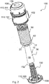
- Figure 1 shows a longitudinal cut view of a filter system 100 according to an embodiment of the invention.
- Figure 2 shows the filter system 100 of Figure 1 in an exploded view.
- the filter system 100 comprises a housing 110, a fluid inlet 102 formed in a housing wall 112, a fluid outlet 108 formed in a bottom housing wall 120.
- the housing 110 may consist of three segments, the bottom housing wall 120, the intermediate ring-shaped housing wall 112 with the fluid inlet 102 and a cover part 114. The segments are connected to each other by, e.g., clamps, screws or the like.
- a hollow cylindrical primary filter element 50 is accommodated in the housing 110.
- the housing walls 112, 114 can be removed from the bottom housing wall 120 together in one piece or only the cover part 114 is removed.
- the body of the primary filter element 50 is made of a filter medium 56 which may be pleated, for instance.
- the primary filter element 50 is covered at both ends by ring shaped first and second end caps 52, 54, which are made, for example, from polyurethane which is well known in the prior art. Sealing structures and supporting ribs are arranged at the exterior sides of the first end cap 42 and the second end cap 54.
- the primary filter element 50 is clamped between the bottom housing wall 120 and the cover housing wall 114 in a sealing tight manner so that a fluid has to pass through the primary filter element 50 in a radial direction, which is indicated by bold arrows in Figure 1 .
- the second end cap 54 of the primary filter element 50 is configured to have a feedthrough for the stand pipe 150 and is accommodated in the bottom housing wall 120 which is provided with a groove 126.
- a ring shaped projection 128 is arranged in the groove 126.
- the cover part 114 In its front face 130, the cover part 114 is provided with a recess 138 which extends into the interior of the housing 110.
- a secondary filter element 10 is arranged inside the primary filter element 50.
- the primary and secondary filter elements 50, 10 are arranged concentrically about an axis extending in a longitudinal direction L.
- the secondary filter element 10 is arranged downstream the primary filter element 50 so that fluid has to pass through the secondary filter element 10 on its way to the fluid outlet 108.
- the secondary filter element 10 is arranged on a stand pipe 150 which is rigidly connected to the bottom housing wall 120. The lower part of the stand pipe 150 merges with the fluid outlet 108 of the bottom housing wall 120.
- the secondary filter element 10 comprises a filter medium 16 forming a body 36 with at least one weld seam 18 along the longitudinal direction L.
- the secondary filter element 10 comprises a closed end cap 20 at its top region 12, wherein the secondary filter element 10 and the stand pipe 150 are mutually connected at their top regions 12, 152 by connection elements.
- the open ended side at the bottom region 14 of the secondary filter element 10 is accommodated in a circular groove 122 in the bottom wall 120.
- the first end cap 52 at the top region of the primary filter element 50 is provided with a protrusion element 58 extending in axial direction towards the top region 12 of the secondary filter element 10.
- the bottom region 55 of the primary filter element 50 and the housing wall 120 accommodating the stand pipe 150 are configured with mutual self-positioning elements 62, 92 to arrange the primary filter element 50 on the housing wall 120 in a defined rotational position with respect to one or more struts 170 of the stand pipe 150.
- the struts 170 are arranged about the longitudinal axis L and are pointing to the interior of the stand pipe 150.
- a radially extending protrusion 64 is arranged at the bottom part 55 of the primary filter element 50 as self-positioning element 62.
- a guiding surface 94 is arranged around the stand pipe 150 as self-positioning element 92.
- the guiding surface 94 is formed as a ramp which has a maximum region with a maximum height in relation to the longitudinal axis L and a minimum region with a minimum height in relation to the longitudinal axis L at the opposite side of the stand pipe 150.
- the radially extending protrusion 64 can glide on the guiding surface 94 from the maximum region to the minimum region when the primary filter element 50 and/or the bottom housing wall 120 are rotated about the longitudinal axis L.
- a notch 96 is arranged in the minimum region in which the radially extending protrusion 64 of the primary filter element 50 can snap into place.
- Figures 3 and 4 show a filter medium 16 and a conical secondary filter element 10 made from the filter medium 16 according to an example embodiment of the invention.
- Figure 3 shows a first embodiment of a cut of a filter medium 16 for secondary filter element 10 in an initial unwound state exhibiting a first edge 13 which is curved in this state and a second edge 15 which is straight.
- the curved dashed line below the straight edge 15 indicates a contour of a typical cut of a filter medium 16 from which a conical filter body is formed.
- the area enclosed by the straight edge 15 in the unwound state of the filter medium 16 and the dashed line shows the area of saved material of filter medium 16 by using a cut with a straight edge 15 for a filter medium 16.
- Figure 4 shows the filter medium 16 exhibiting the cut shown in Figure 3 in a final wound state forming the conical filter body 36 of the filter element 10 exhibiting the first edge 13 at the top region 12 being straight and the second edge 15 at the bottom region 14 being curved.
- the sides of the cut are closed by means of a welded seam 18, for instance.
- the filter medium is wound to form a tree dimensional filter body 36, in this example a conical filter body 36
- the edge 15 at the region 14 of the filter body 36 of the filter element 10 is curved.
- This cut results in the secondary filter element 10 having a preferred orientation which can be used for a specific rotational orientation of the secondary filter element 10 in a housing of a filter system.
- Figure 5 shows a conventional filter medium 16 wound to a standard conical filter body 36 with upper and lower straight edges of the filter body 36, while in the unwound state the cut exhibits curved edges at both ends of the filter medium 16.
- Figure 6 shows a detail of a cut view of a housing wall 120, for instance the bottom wall 120 of a housing 110, comprising a stand pipe 150 rigidly attached to, the stand pipe 150 comprising a sealing structure 127 for accommodating a secondary filter element 10 according to an embodiment of the invention.
- the lattice-like body of the stand pipe 150 is conically shaped and composed of longitudinal struts 170 and circumferential struts 172.
- a circular groove 122 is provided for receiving the open-ended side at the bottom region 14 of the secondary filter element 10 ( Figure 4 ) in the housing wall 120.
- the open-ended side at the bottom region 14 of the secondary filter element 10 as shown in Figure 4 comprises an edge 15 which has a curved contour, whereas the opposite side of the secondary filter element 10 is provided with a straight edge 13 at its top region 12.
- the primary filter element 50 is intended to be clamped between the bottom housing wall 120 and a cover housing wall 114 ( Figure 1 ) in a sealing tight manner so that a fluid has to pass through the primary filter element 50 in a radial direction, the second end cap 54 of the primary filter element 50 is configured to have a feedthrough for the stand pipe 150 and is accommodated in a groove 126 of the bottom housing wall 120.
- a ring shaped projection 128 is arranged in the groove 126.
- a sealing structure 127 for sealing the secondary filter element 10 is arranged about the stand pipe 150 close to the interface between stand pipe 150 and housing wall 120.
- the sealing structure comprises a pocket 122 for accommodating the secondary filter element 10.
- the pocket 121 comprises a bottom 124 following the contour 121 of the sealing structure 127.
- the contour 121 of the sealing structure 127 declines from a maximum point 123 at one side of the stand pipe 150 to a minimum point 125 at the opposite side of the stand pipe 150 in a continuous manner.
- a height H125 of the minimum point 125 is lower than the bottom 124 of the pocket 122 at the maximum point 123 in relation to the longitudinal axis, i.e. the height H125 of the minimum point 125 has a shorter extension along the longitudinal axis L measured from a base line 129 than an extension along the longitudinal axis L from the base line 129 to the bottom 124 of the pocket 122 at the maximum point 123.
- the base line 129 is in particular arranged perpendicular to the longitudinal axis L.
- This decline of the contour of the sealing structure 127 causes a big enough height difference between the maximum point 123 and the minimum point 125 so that the secondary filter element 10 can be inserted in the pocket 122 with its edge 15 in a suitably oriented and non-interchangeable manner.
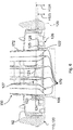
- Figures 7 and 8 illustrate a bottom housing wall 120 and a primary filter element 50 which cooperate via self-positioning elements 92 and 62, according to an embodiment of the invention and which can be readily combined with the inventive secondary filter element 10.
- Figure 7 shows the housing wall 120 with a rigidly attached stand pipe 150 and Figure 8 depicts the primary filter element 50 in a side view.
- the interior of the stand pipe 150 is in fluid connection with the fluid outlet 108.
- the stand pipe 150 is surrounded by a self-positioning element 92 being configured as guiding surface 94 having the shape of a ring ramp.
- the guiding surface 94 is formed as a ramp which has a maximum region with a maximum height in relation to the longitudinal axis L and a minimum region with a minimum height in relation to the longitudinal axis L at the opposite side of the stand pipe 150.
- a self-positioning element 62 configured as a radially extending protrusion 64 can glide on the guiding surface 94 from the maximum region to the minimum region when the primary filter element 50 and/or the bottom housing wall 120 are rotated about the longitudinal axis L.
- a notch 96 is arranged in the minimum region in which the radially extending protrusion 64 of the primary filter element 50 can snap into place.
- the primary filter element 50 in Figure 8 comprises a radially extending protrusion 64 at the outer circumference of the second end cap 54.
- the radially protruding element 64 can be arranged on a ring 60 for accommodating the filter medium 56 of the primary filter element 10 comprising a radially extending protrusion 64 at the outer circumference of its second end cap 54.
- the primary filter element 50 has a filter body consisting of a filter medium 56 which extends between a first end cap 52 and a second end cap 54 which has a feedthrough for the stand pipe 150 ( Figures 5 and 6 ).
- the filter medium 56 is attached to the outer surface of a support structure 70 arranged in the interior of the primary filter element 50.
- a self-positioning element 62 configured as a radially extending protrusion 64 is arranged at the second end cap 54.
- the radially extending protrusion 64 is part of a ring 60 which is embedded in the material of the second end cap 54.
- the ring 60 is shown in Figure 8 .
- the ring 60 accommodates the filter body consisting of the filter medium 56 in its interior.
- the ring 60 has an outer rim which overlaps the bottom part of the filter body in axial direction.
- Figure 9 shows a detail of an embodiment of a secondary filter element 10 which is mounted to a stand pipe 150 before the secondary filter element 10 is put in its final position.
- the body 36 of the secondary filter element 10 is put over and moved along the stand pipe 150 until the end cap 20 comes close the receptacle 160 of the stand pipe 150.
- the stand pipe 150 in this embodiment comprises a receptacle 160 at its top region 152.
- the contour of the receptacle 160 corresponds to the exterior contour of the end cap 20 of the secondary filter element 10.
- the receptacle 160 has an open ended bottom which ends in a connection element 156 for the connection elements 22 of the secondary filter element 10. For instance, snap beams 23 can be hooked on the bottom of the receptacle 160 as locking element and establish a snap fit connection between the stand pipe 150 and the secondary filter element 10.
- the receptacle 160 is funnel shaped in its bottom region so that introducing the snap beams is facilitated.
- the end cap 20 enters the receptacle 160 towards the funnel-shaped bottom region of the receptacle 160 with the snap beams 23 first.
- the end cap 20 can be introduced into the receptacle 160 until the projection element 32 hits the guiding surface 182.
- the longitudinal extension 90 of the projection element 32 is smaller than the depth 168 of the top segment 162 of the receptacle 160.
- the upper segment 21 of the end cap can be immersed partly into the top segment 162 so that the step 25 is safely inside the receptacle 160.
- the end cap 20 can be guided further into the receptacle 160 safely without tilting.
- the guiding surface 182 has one maximum point 190 in the bottom segment 164 of the receptacle 160 and is inclined on both sides of the maximum point 190.
- the maximum point 190 of the guiding surface 182 is at the interface between the top segment 162 and the bottom segment 164 of the receptacle 160.
- the end cap 20 now is moved axially until the projection element 32 is accommodated in the pocket 186.
- the snap beams 23 move axially downward, too, they can snap over the rim of the funnel shaped bottom segment 164.
- the rim is the locking element 157 of the stand pipe 150.
- the snap beams 23 lock the end cap 20 safely to the stand pipe 150.
- the end cap 20 may be removed from the stand pipe 150 by an opposite sequence of movement by pulling and turning the end cap 20.
- a tool such as a handle or the like can be applied to the recess 24 of the end cap 20.
- the secondary filter element 10 With the projection element 32 accommodated in the pocket 186, the secondary filter element 10 is positioned accurately in a well-defined rotational position with respect to the stand pipe 150.
- the longitudinal weld seam (not shown) is in a distinct position with respect to the longitudinal struts 170 of the stand pipe 150 and, consequently, to a mass flow sensor arranged at a fixed position close to the filter elements.
- the hooks at the snap beams 23 are provided with inclined surfaces so that these can come loose when some force is applied to the end cap 20.
- the length of the end cap 20 with snap beams 23 is matched to the depth of the receptacle 160 so that the snap beams 23 come into contact with the rim, i.e. the locking element 157, of the funnel shaped end of the receptacle 160 with the projection element 32 reaching its end position in the pocket 186.
- the step 25 of the end cap 20 rests on the maximum point 190 of the guiding surface 182 in the receptacle 160.
Landscapes
- Chemical & Material Sciences (AREA)
- Chemical Kinetics & Catalysis (AREA)
- Engineering & Computer Science (AREA)
- Physics & Mathematics (AREA)
- Geometry (AREA)
- Combustion & Propulsion (AREA)
- Mechanical Engineering (AREA)
- General Engineering & Computer Science (AREA)
- Filtering Of Dispersed Particles In Gases (AREA)
- Filtration Of Liquid (AREA)
Priority Applications (7)
| Application Number | Priority Date | Filing Date | Title |
|---|---|---|---|
| EP19182975.3A EP3756748A1 (fr) | 2019-06-27 | 2019-06-27 | Système de filtre doté d'un élément filtrant primaire et d'un élément filtrant secondaire et élément filtrant secondaire pour un tel système de filtre |
| EP20732983.0A EP3990151B1 (fr) | 2019-06-27 | 2020-06-19 | Système de filtre doté d'un élément filtrant primaire et d'un élément filtrant secondaire et élément filtrant secondaire pour un tel système de filtre |
| JP2021576851A JP2022538256A (ja) | 2019-06-27 | 2020-06-19 | 一次および二次濾過要素を備える濾過システム、二次濾過要素、ならびに方法 |
| CN202080046978.5A CN113993609A (zh) | 2019-06-27 | 2020-06-19 | 具有初级和次级过滤器元件的过滤器系统、次级过滤器元件和方法 |
| PCT/EP2020/067185 WO2020260161A1 (fr) | 2019-06-27 | 2020-06-19 | Système de filtration comprenant un élément de filtre primaire et un élément de filtre secondaire, élément de filtre secondaire et procédé |
| BR112021023806A BR112021023806A8 (pt) | 2019-06-27 | 2020-06-19 | Sistema de filtro que possui um elemento de filtro primário e um secundário, elemento de filtro secundário e método |
| US17/562,342 US12023621B2 (en) | 2019-06-27 | 2021-12-27 | Filter system having a primary and a secondary filter element, secondary filter element and method |
Applications Claiming Priority (1)
| Application Number | Priority Date | Filing Date | Title |
|---|---|---|---|
| EP19182975.3A EP3756748A1 (fr) | 2019-06-27 | 2019-06-27 | Système de filtre doté d'un élément filtrant primaire et d'un élément filtrant secondaire et élément filtrant secondaire pour un tel système de filtre |
Publications (1)
| Publication Number | Publication Date |
|---|---|
| EP3756748A1 true EP3756748A1 (fr) | 2020-12-30 |
Family
ID=67105926
Family Applications (2)
| Application Number | Title | Priority Date | Filing Date |
|---|---|---|---|
| EP19182975.3A Withdrawn EP3756748A1 (fr) | 2019-06-27 | 2019-06-27 | Système de filtre doté d'un élément filtrant primaire et d'un élément filtrant secondaire et élément filtrant secondaire pour un tel système de filtre |
| EP20732983.0A Active EP3990151B1 (fr) | 2019-06-27 | 2020-06-19 | Système de filtre doté d'un élément filtrant primaire et d'un élément filtrant secondaire et élément filtrant secondaire pour un tel système de filtre |
Family Applications After (1)
| Application Number | Title | Priority Date | Filing Date |
|---|---|---|---|
| EP20732983.0A Active EP3990151B1 (fr) | 2019-06-27 | 2020-06-19 | Système de filtre doté d'un élément filtrant primaire et d'un élément filtrant secondaire et élément filtrant secondaire pour un tel système de filtre |
Country Status (6)
| Country | Link |
|---|---|
| US (1) | US12023621B2 (fr) |
| EP (2) | EP3756748A1 (fr) |
| JP (1) | JP2022538256A (fr) |
| CN (1) | CN113993609A (fr) |
| BR (1) | BR112021023806A8 (fr) |
| WO (1) | WO2020260161A1 (fr) |
Cited By (1)
| Publication number | Priority date | Publication date | Assignee | Title |
|---|---|---|---|---|
| EP4223386A1 (fr) * | 2022-02-03 | 2023-08-09 | MANN+HUMMEL GmbH | Système de filtre comportant un élément de filtre primaire et un élément de filtre secondaire, élément de filtre secondaire et procédé |
Citations (7)
| Publication number | Priority date | Publication date | Assignee | Title |
|---|---|---|---|---|
| US20040031748A1 (en) * | 2000-12-21 | 2004-02-19 | Mann & Hummel Gmbh | Filter element |
| US7828870B1 (en) * | 2004-11-24 | 2010-11-09 | Cummins Filtration Ip, Inc. | Filter assembly with cost effective seal |
| US8480778B2 (en) | 2007-07-20 | 2013-07-09 | Donaldson Company, Inc. | Air cleaner arrangements; components; and, methods |
| US20140144111A1 (en) * | 2012-11-29 | 2014-05-29 | Donaldson Company Inc. | Filter cartridges; features and methods of assemlby; air cleaner assemblies; and, filter cartridge combinations |
| US20160296868A1 (en) * | 2015-04-10 | 2016-10-13 | Mann+Hummel Gmbh | Filter holder, filter element and filter arrangement |
| US20180036667A1 (en) * | 2015-04-20 | 2018-02-08 | Mann+Hummel Gmbh | Secondary Element for a Filter System and Filter System with a Secondary Element |
| WO2018111434A2 (fr) * | 2016-11-04 | 2018-06-21 | Donaldson Company, Inc. | Éléments filtrants, ensembles purificateurs d'air, et procédés d'utilisation et d'assemblage |
Family Cites Families (5)
| Publication number | Priority date | Publication date | Assignee | Title |
|---|---|---|---|---|
| US7070642B2 (en) | 2002-10-28 | 2006-07-04 | Donaldson Company, Inc. | Air cleaner; replaceable filter cartridges; and, methods |
| CN103442782A (zh) | 2011-02-25 | 2013-12-11 | 唐纳森公司 | 空气过滤器滤芯、其部件和空气滤清器组件 |
| DE102013014488A1 (de) | 2013-09-02 | 2015-03-05 | Mann + Hummel Gmbh | Filtersystem und Filterelement für ein Filtersystem |
| DE102016003454A1 (de) | 2015-04-10 | 2016-10-13 | Mann + Hummel Gmbh | Filteraufnahme und Filteranordnung |
| EP3413993B1 (fr) | 2016-02-12 | 2023-08-23 | Donaldson Company, Inc. | Éléments filtrants et ensemble épurateur d'air |
-
2019
- 2019-06-27 EP EP19182975.3A patent/EP3756748A1/fr not_active Withdrawn
-
2020
- 2020-06-19 WO PCT/EP2020/067185 patent/WO2020260161A1/fr active Application Filing
- 2020-06-19 EP EP20732983.0A patent/EP3990151B1/fr active Active
- 2020-06-19 CN CN202080046978.5A patent/CN113993609A/zh active Pending
- 2020-06-19 JP JP2021576851A patent/JP2022538256A/ja active Pending
- 2020-06-19 BR BR112021023806A patent/BR112021023806A8/pt unknown
-
2021
- 2021-12-27 US US17/562,342 patent/US12023621B2/en active Active
Patent Citations (7)
| Publication number | Priority date | Publication date | Assignee | Title |
|---|---|---|---|---|
| US20040031748A1 (en) * | 2000-12-21 | 2004-02-19 | Mann & Hummel Gmbh | Filter element |
| US7828870B1 (en) * | 2004-11-24 | 2010-11-09 | Cummins Filtration Ip, Inc. | Filter assembly with cost effective seal |
| US8480778B2 (en) | 2007-07-20 | 2013-07-09 | Donaldson Company, Inc. | Air cleaner arrangements; components; and, methods |
| US20140144111A1 (en) * | 2012-11-29 | 2014-05-29 | Donaldson Company Inc. | Filter cartridges; features and methods of assemlby; air cleaner assemblies; and, filter cartridge combinations |
| US20160296868A1 (en) * | 2015-04-10 | 2016-10-13 | Mann+Hummel Gmbh | Filter holder, filter element and filter arrangement |
| US20180036667A1 (en) * | 2015-04-20 | 2018-02-08 | Mann+Hummel Gmbh | Secondary Element for a Filter System and Filter System with a Secondary Element |
| WO2018111434A2 (fr) * | 2016-11-04 | 2018-06-21 | Donaldson Company, Inc. | Éléments filtrants, ensembles purificateurs d'air, et procédés d'utilisation et d'assemblage |
Cited By (1)
| Publication number | Priority date | Publication date | Assignee | Title |
|---|---|---|---|---|
| EP4223386A1 (fr) * | 2022-02-03 | 2023-08-09 | MANN+HUMMEL GmbH | Système de filtre comportant un élément de filtre primaire et un élément de filtre secondaire, élément de filtre secondaire et procédé |
Also Published As
| Publication number | Publication date |
|---|---|
| BR112021023806A2 (pt) | 2022-01-04 |
| WO2020260161A1 (fr) | 2020-12-30 |
| CN113993609A (zh) | 2022-01-28 |
| US12023621B2 (en) | 2024-07-02 |
| EP3990151A1 (fr) | 2022-05-04 |
| BR112021023806A8 (pt) | 2023-02-28 |
| JP2022538256A (ja) | 2022-09-01 |
| US20220118399A1 (en) | 2022-04-21 |
| EP3990151B1 (fr) | 2023-05-24 |
Similar Documents
| Publication | Publication Date | Title |
|---|---|---|
| EP3990153B1 (fr) | Système de filtre doté d'un élément filtrant primaire et d'un élément filtrant secondaire et élément filtrant secondaire pour un tel système de filtre | |
| US10408173B2 (en) | Filter element | |
| US11007462B2 (en) | Air cleaner; replaceable filter cartridges; and, methods | |
| KR101501796B1 (ko) | 필터 엘리먼트 및 필터 시스템 | |
| US11192057B2 (en) | Secondary element for a filter system and filter system with a secondary element | |
| EP2763779B1 (fr) | Ensemble de cartouche filtrante | |
| EP1558357B1 (fr) | Systeme de retenue par interference excentrique pour cartouche filtrante | |
| US9914085B2 (en) | Filter element and filter system | |
| US12023621B2 (en) | Filter system having a primary and a secondary filter element, secondary filter element and method | |
| US20220118398A1 (en) | Filter system having a primary and a secondary filter element and primary filter element for such a filter system | |
| EP4223386A1 (fr) | Système de filtre comportant un élément de filtre primaire et un élément de filtre secondaire, élément de filtre secondaire et procédé | |
| US12134061B2 (en) | Filter system having a primary and a secondary filter element and secondary filter element for such a filter system | |
| EP4223384A1 (fr) | Système de filtre doté d'un élément filtrant primaire et d'un élément filtrant secondaire et élément filtrant primaire pour un tel système de filtre | |
| US6143046A (en) | Filter cartridge having vibratable diaphragm | |
| EP4223383A1 (fr) | Système de filtre doté d'un élément filtrant primaire et d'un élément filtrant secondaire et élément filtrant primaire pour un tel système de filtre | |
| EP3473321A1 (fr) | Système de filtre comportant un élément filtrant et élément filtrant pour un tel système de filtre |
Legal Events
| Date | Code | Title | Description |
|---|---|---|---|
| PUAI | Public reference made under article 153(3) epc to a published international application that has entered the european phase |
Free format text: ORIGINAL CODE: 0009012 |
|
| STAA | Information on the status of an ep patent application or granted ep patent |
Free format text: STATUS: THE APPLICATION HAS BEEN PUBLISHED |
|
| AK | Designated contracting states |
Kind code of ref document: A1 Designated state(s): AL AT BE BG CH CY CZ DE DK EE ES FI FR GB GR HR HU IE IS IT LI LT LU LV MC MK MT NL NO PL PT RO RS SE SI SK SM TR |
|
| AX | Request for extension of the european patent |
Extension state: BA ME |
|
| RAP3 | Party data changed (applicant data changed or rights of an application transferred) |
Owner name: MANN+HUMMEL GMBH |
|
| STAA | Information on the status of an ep patent application or granted ep patent |
Free format text: STATUS: THE APPLICATION HAS BEEN WITHDRAWN |
|
| 18W | Application withdrawn |
Effective date: 20210629 |