US6673136B2 - Air filtration arrangements having fluted media constructions and methods - Google Patents
Air filtration arrangements having fluted media constructions and methods Download PDFInfo
- Publication number
- US6673136B2 US6673136B2 US09/871,590 US87159001A US6673136B2 US 6673136 B2 US6673136 B2 US 6673136B2 US 87159001 A US87159001 A US 87159001A US 6673136 B2 US6673136 B2 US 6673136B2
- Authority
- US
- United States
- Prior art keywords
- air
- filter
- polymer
- media
- fiber
- Prior art date
- Legal status (The legal status is an assumption and is not a legal conclusion. Google has not performed a legal analysis and makes no representation as to the accuracy of the status listed.)
- Expired - Lifetime
Links
- 238000010276 construction Methods 0.000 title claims description 70
- 238000000034 method Methods 0.000 title claims description 59
- 238000001914 filtration Methods 0.000 title claims description 53
- 239000000835 fiber Substances 0.000 claims abstract description 274
- 239000000446 fuel Substances 0.000 claims abstract description 39
- 229920000642 polymer Polymers 0.000 claims description 170
- 239000000463 material Substances 0.000 claims description 132
- 239000000203 mixture Substances 0.000 claims description 91
- 239000000758 substrate Substances 0.000 claims description 89
- 239000000654 additive Substances 0.000 claims description 57
- 230000000996 additive effect Effects 0.000 claims description 48
- IISBACLAFKSPIT-UHFFFAOYSA-N bisphenol A Chemical compound C=1C=C(O)C=CC=1C(C)(C)C1=CC=C(O)C=C1 IISBACLAFKSPIT-UHFFFAOYSA-N 0.000 claims description 38
- 229920001778 nylon Polymers 0.000 claims description 38
- 238000007789 sealing Methods 0.000 claims description 38
- 239000004952 Polyamide Substances 0.000 claims description 32
- 229920002647 polyamide Polymers 0.000 claims description 32
- 238000012360 testing method Methods 0.000 claims description 31
- 239000002131 composite material Substances 0.000 claims description 24
- 239000004677 Nylon Substances 0.000 claims description 23
- 238000011144 upstream manufacturing Methods 0.000 claims description 21
- -1 cyclic lactam Chemical class 0.000 claims description 17
- 229920002451 polyvinyl alcohol Polymers 0.000 claims description 17
- 229920005989 resin Polymers 0.000 claims description 15
- 239000011347 resin Substances 0.000 claims description 15
- WJQOZHYUIDYNHM-UHFFFAOYSA-N 2-tert-Butylphenol Chemical compound CC(C)(C)C1=CC=CC=C1O WJQOZHYUIDYNHM-UHFFFAOYSA-N 0.000 claims description 14
- 239000004372 Polyvinyl alcohol Substances 0.000 claims description 13
- 125000004183 alkoxy alkyl group Chemical group 0.000 claims description 13
- 238000000576 coating method Methods 0.000 claims description 13
- 238000009833 condensation Methods 0.000 claims description 13
- 230000005494 condensation Effects 0.000 claims description 13
- 235000019422 polyvinyl alcohol Nutrition 0.000 claims description 13
- 239000011248 coating agent Substances 0.000 claims description 11
- 230000001629 suppression Effects 0.000 claims description 11
- 229920001577 copolymer Polymers 0.000 claims description 10
- 230000008018 melting Effects 0.000 claims description 9
- 238000002844 melting Methods 0.000 claims description 9
- 239000004687 Nylon copolymer Substances 0.000 claims description 6
- 229920001328 Polyvinylidene chloride Polymers 0.000 claims description 5
- 239000005033 polyvinylidene chloride Substances 0.000 claims description 5
- 239000002033 PVDF binder Substances 0.000 claims description 4
- 239000004793 Polystyrene Substances 0.000 claims description 4
- 230000004323 axial length Effects 0.000 claims description 4
- 229920002223 polystyrene Polymers 0.000 claims description 4
- 229920002981 polyvinylidene fluoride Polymers 0.000 claims description 4
- 125000003118 aryl group Chemical group 0.000 claims description 3
- 239000003431 cross linking reagent Substances 0.000 claims description 3
- 229920001519 homopolymer Polymers 0.000 claims description 3
- 229920000139 polyethylene terephthalate Polymers 0.000 claims description 3
- 239000005020 polyethylene terephthalate Substances 0.000 claims description 3
- 229920002635 polyurethane Polymers 0.000 claims description 3
- 239000004814 polyurethane Substances 0.000 claims description 3
- 239000012798 spherical particle Substances 0.000 claims description 3
- 239000004094 surface-active agent Substances 0.000 claims description 3
- IMROMDMJAWUWLK-UHFFFAOYSA-N Ethenol Chemical compound OC=C IMROMDMJAWUWLK-UHFFFAOYSA-N 0.000 claims description 2
- 229920000877 Melamine resin Polymers 0.000 claims description 2
- 229920002125 Sokalan® Polymers 0.000 claims description 2
- 239000002736 nonionic surfactant Substances 0.000 claims description 2
- 239000004584 polyacrylic acid Substances 0.000 claims description 2
- 239000000178 monomer Substances 0.000 claims 4
- 150000004985 diamines Chemical class 0.000 claims 3
- 229920006214 polyvinylidene halide Polymers 0.000 claims 3
- 239000007795 chemical reaction product Substances 0.000 claims 2
- 229920001230 polyarylate Polymers 0.000 claims 2
- 229920001283 Polyalkylene terephthalate Polymers 0.000 claims 1
- 239000004693 Polybenzimidazole Substances 0.000 claims 1
- 239000004760 aramid Substances 0.000 claims 1
- 229920003235 aromatic polyamide Polymers 0.000 claims 1
- VCCBEIPGXKNHFW-UHFFFAOYSA-N biphenyl-4,4'-diol Chemical group C1=CC(O)=CC=C1C1=CC=C(O)C=C1 VCCBEIPGXKNHFW-UHFFFAOYSA-N 0.000 claims 1
- IMHDGJOMLMDPJN-UHFFFAOYSA-N dihydroxybiphenyl Natural products OC1=CC=CC=C1C1=CC=CC=C1O IMHDGJOMLMDPJN-UHFFFAOYSA-N 0.000 claims 1
- 239000000945 filler Substances 0.000 claims 1
- NBVXSUQYWXRMNV-UHFFFAOYSA-N fluoromethane Chemical compound FC NBVXSUQYWXRMNV-UHFFFAOYSA-N 0.000 claims 1
- 229920002313 fluoropolymer Polymers 0.000 claims 1
- 239000004811 fluoropolymer Substances 0.000 claims 1
- 125000005487 naphthalate group Chemical group 0.000 claims 1
- 150000003022 phthalic acids Chemical class 0.000 claims 1
- 229920000889 poly(m-phenylene isophthalamide) Polymers 0.000 claims 1
- 229920003366 poly(p-phenylene terephthalamide) Polymers 0.000 claims 1
- 229920001281 polyalkylene Polymers 0.000 claims 1
- 229920002480 polybenzimidazole Polymers 0.000 claims 1
- 238000012643 polycondensation polymerization Methods 0.000 claims 1
- 239000002954 polymerization reaction product Substances 0.000 claims 1
- 229920001291 polyvinyl halide Polymers 0.000 claims 1
- 230000004888 barrier function Effects 0.000 abstract description 12
- 239000003570 air Substances 0.000 description 222
- 239000010410 layer Substances 0.000 description 82
- XLYOFNOQVPJJNP-UHFFFAOYSA-N water Substances O XLYOFNOQVPJJNP-UHFFFAOYSA-N 0.000 description 58
- 239000000523 sample Substances 0.000 description 53
- LFQSCWFLJHTTHZ-UHFFFAOYSA-N Ethanol Chemical compound CCO LFQSCWFLJHTTHZ-UHFFFAOYSA-N 0.000 description 52
- 239000007789 gas Substances 0.000 description 47
- 239000012530 fluid Substances 0.000 description 42
- 239000003658 microfiber Substances 0.000 description 41
- 229920001410 Microfiber Polymers 0.000 description 37
- 239000003463 adsorbent Substances 0.000 description 36
- 239000000243 solution Substances 0.000 description 30
- 230000000717 retained effect Effects 0.000 description 28
- 239000002904 solvent Substances 0.000 description 28
- 239000002245 particle Substances 0.000 description 25
- OKTJSMMVPCPJKN-UHFFFAOYSA-N Carbon Chemical class [C] OKTJSMMVPCPJKN-UHFFFAOYSA-N 0.000 description 24
- 239000011236 particulate material Substances 0.000 description 24
- 239000000356 contaminant Substances 0.000 description 22
- 229920002302 Nylon 6,6 Polymers 0.000 description 21
- 239000000126 substance Substances 0.000 description 21
- OKKJLVBELUTLKV-UHFFFAOYSA-N Methanol Chemical compound OC OKKJLVBELUTLKV-UHFFFAOYSA-N 0.000 description 20
- 238000004140 cleaning Methods 0.000 description 20
- 239000001913 cellulose Substances 0.000 description 19
- 229920002678 cellulose Polymers 0.000 description 19
- 235000010980 cellulose Nutrition 0.000 description 19
- 239000002121 nanofiber Substances 0.000 description 19
- 230000015572 biosynthetic process Effects 0.000 description 18
- 239000000428 dust Substances 0.000 description 18
- 230000008569 process Effects 0.000 description 18
- 239000002657 fibrous material Substances 0.000 description 16
- 239000007788 liquid Substances 0.000 description 16
- 238000013461 design Methods 0.000 description 15
- 230000035699 permeability Effects 0.000 description 15
- 238000011045 prefiltration Methods 0.000 description 14
- 230000002378 acidificating effect Effects 0.000 description 12
- 239000011230 binding agent Substances 0.000 description 12
- 239000003054 catalyst Substances 0.000 description 12
- KRKNYBCHXYNGOX-UHFFFAOYSA-N citric acid Chemical compound OC(=O)CC(O)(C(O)=O)CC(O)=O KRKNYBCHXYNGOX-UHFFFAOYSA-N 0.000 description 12
- 230000007246 mechanism Effects 0.000 description 12
- 239000007787 solid Substances 0.000 description 12
- 238000004833 X-ray photoelectron spectroscopy Methods 0.000 description 11
- 238000011068 loading method Methods 0.000 description 11
- IJGRMHOSHXDMSA-UHFFFAOYSA-N Atomic nitrogen Chemical compound N#N IJGRMHOSHXDMSA-UHFFFAOYSA-N 0.000 description 10
- 238000006243 chemical reaction Methods 0.000 description 10
- 238000004132 cross linking Methods 0.000 description 10
- 238000010438 heat treatment Methods 0.000 description 10
- 230000014759 maintenance of location Effects 0.000 description 10
- CSCPPACGZOOCGX-UHFFFAOYSA-N Acetone Chemical compound CC(C)=O CSCPPACGZOOCGX-UHFFFAOYSA-N 0.000 description 9
- WSFSSNUMVMOOMR-UHFFFAOYSA-N Formaldehyde Chemical compound O=C WSFSSNUMVMOOMR-UHFFFAOYSA-N 0.000 description 9
- 229920003189 Nylon 4,6 Polymers 0.000 description 9
- 239000011324 bead Substances 0.000 description 9
- 238000004519 manufacturing process Methods 0.000 description 9
- KFZMGEQAYNKOFK-UHFFFAOYSA-N Isopropanol Chemical compound CC(C)O KFZMGEQAYNKOFK-UHFFFAOYSA-N 0.000 description 8
- 230000008901 benefit Effects 0.000 description 8
- 229910052799 carbon Inorganic materials 0.000 description 8
- 238000009472 formulation Methods 0.000 description 8
- 238000007654 immersion Methods 0.000 description 8
- 239000002861 polymer material Substances 0.000 description 8
- 229920002292 Nylon 6 Polymers 0.000 description 7
- ISWSIDIOOBJBQZ-UHFFFAOYSA-N Phenol Chemical compound OC1=CC=CC=C1 ISWSIDIOOBJBQZ-UHFFFAOYSA-N 0.000 description 7
- 230000000694 effects Effects 0.000 description 7
- 239000001257 hydrogen Substances 0.000 description 7
- 229910052739 hydrogen Inorganic materials 0.000 description 7
- 229920000728 polyester Polymers 0.000 description 7
- 239000000047 product Substances 0.000 description 7
- 238000010521 absorption reaction Methods 0.000 description 6
- 238000004458 analytical method Methods 0.000 description 6
- 238000007906 compression Methods 0.000 description 6
- 230000006835 compression Effects 0.000 description 6
- 238000011161 development Methods 0.000 description 6
- 230000018109 developmental process Effects 0.000 description 6
- 230000002829 reductive effect Effects 0.000 description 6
- UFHFLCQGNIYNRP-UHFFFAOYSA-N Hydrogen Chemical compound [H][H] UFHFLCQGNIYNRP-UHFFFAOYSA-N 0.000 description 5
- VYPSYNLAJGMNEJ-UHFFFAOYSA-N Silicium dioxide Chemical compound O=[Si]=O VYPSYNLAJGMNEJ-UHFFFAOYSA-N 0.000 description 5
- 150000001298 alcohols Chemical class 0.000 description 5
- 239000007822 coupling agent Substances 0.000 description 5
- 238000001523 electrospinning Methods 0.000 description 5
- 238000005516 engineering process Methods 0.000 description 5
- 239000012634 fragment Substances 0.000 description 5
- 230000006870 function Effects 0.000 description 5
- 239000008187 granular material Substances 0.000 description 5
- 230000002209 hydrophobic effect Effects 0.000 description 5
- 230000004048 modification Effects 0.000 description 5
- 238000012986 modification Methods 0.000 description 5
- 229910052757 nitrogen Inorganic materials 0.000 description 5
- 229920003023 plastic Polymers 0.000 description 5
- 239000004033 plastic Substances 0.000 description 5
- 229920002959 polymer blend Polymers 0.000 description 5
- 238000012545 processing Methods 0.000 description 5
- 230000002441 reversible effect Effects 0.000 description 5
- 238000002791 soaking Methods 0.000 description 5
- 238000001179 sorption measurement Methods 0.000 description 5
- 238000009987 spinning Methods 0.000 description 5
- 229920001897 terpolymer Polymers 0.000 description 5
- 125000000999 tert-butyl group Chemical group [H]C([H])([H])C(*)(C([H])([H])[H])C([H])([H])[H] 0.000 description 5
- KXGFMDJXCMQABM-UHFFFAOYSA-N 2-methoxy-6-methylphenol Chemical compound [CH]OC1=CC=CC([CH])=C1O KXGFMDJXCMQABM-UHFFFAOYSA-N 0.000 description 4
- QGZKDVFQNNGYKY-UHFFFAOYSA-N Ammonia Chemical compound N QGZKDVFQNNGYKY-UHFFFAOYSA-N 0.000 description 4
- CURLTUGMZLYLDI-UHFFFAOYSA-N Carbon dioxide Chemical compound O=C=O CURLTUGMZLYLDI-UHFFFAOYSA-N 0.000 description 4
- LRHPLDYGYMQRHN-UHFFFAOYSA-N N-Butanol Chemical compound CCCCO LRHPLDYGYMQRHN-UHFFFAOYSA-N 0.000 description 4
- 229920000305 Nylon 6,10 Polymers 0.000 description 4
- HEMHJVSKTPXQMS-UHFFFAOYSA-M Sodium hydroxide Chemical class [OH-].[Na+] HEMHJVSKTPXQMS-UHFFFAOYSA-M 0.000 description 4
- 239000002253 acid Substances 0.000 description 4
- 238000004364 calculation method Methods 0.000 description 4
- 238000002485 combustion reaction Methods 0.000 description 4
- 238000001035 drying Methods 0.000 description 4
- 230000005686 electrostatic field Effects 0.000 description 4
- 230000007613 environmental effect Effects 0.000 description 4
- 230000006698 induction Effects 0.000 description 4
- 239000004816 latex Substances 0.000 description 4
- 229920000126 latex Polymers 0.000 description 4
- BDAGIHXWWSANSR-UHFFFAOYSA-N methanoic acid Natural products OC=O BDAGIHXWWSANSR-UHFFFAOYSA-N 0.000 description 4
- 229920001568 phenolic resin Polymers 0.000 description 4
- 239000005011 phenolic resin Substances 0.000 description 4
- 230000000704 physical effect Effects 0.000 description 4
- 239000011148 porous material Substances 0.000 description 4
- 241000894007 species Species 0.000 description 4
- 239000012906 subvisible particle Substances 0.000 description 4
- 239000012209 synthetic fiber Substances 0.000 description 4
- RNFJDJUURJAICM-UHFFFAOYSA-N 2,2,4,4,6,6-hexaphenoxy-1,3,5-triaza-2$l^{5},4$l^{5},6$l^{5}-triphosphacyclohexa-1,3,5-triene Chemical compound N=1P(OC=2C=CC=CC=2)(OC=2C=CC=CC=2)=NP(OC=2C=CC=CC=2)(OC=2C=CC=CC=2)=NP=1(OC=1C=CC=CC=1)OC1=CC=CC=C1 RNFJDJUURJAICM-UHFFFAOYSA-N 0.000 description 3
- LBLYYCQCTBFVLH-UHFFFAOYSA-N 2-Methylbenzenesulfonic acid Chemical compound CC1=CC=CC=C1S(O)(=O)=O LBLYYCQCTBFVLH-UHFFFAOYSA-N 0.000 description 3
- QHPQWRBYOIRBIT-UHFFFAOYSA-N 4-tert-butylphenol Chemical compound CC(C)(C)C1=CC=C(O)C=C1 QHPQWRBYOIRBIT-UHFFFAOYSA-N 0.000 description 3
- 229920003043 Cellulose fiber Polymers 0.000 description 3
- 239000012298 atmosphere Substances 0.000 description 3
- QVGXLLKOCUKJST-UHFFFAOYSA-N atomic oxygen Chemical compound [O] QVGXLLKOCUKJST-UHFFFAOYSA-N 0.000 description 3
- 230000015556 catabolic process Effects 0.000 description 3
- 238000011109 contamination Methods 0.000 description 3
- 238000006731 degradation reaction Methods 0.000 description 3
- 230000009977 dual effect Effects 0.000 description 3
- 238000010041 electrostatic spinning Methods 0.000 description 3
- 239000004744 fabric Substances 0.000 description 3
- 239000003063 flame retardant Substances 0.000 description 3
- 239000011521 glass Substances 0.000 description 3
- 125000002887 hydroxy group Chemical group [H]O* 0.000 description 3
- 230000006872 improvement Effects 0.000 description 3
- 239000012528 membrane Substances 0.000 description 3
- 238000002156 mixing Methods 0.000 description 3
- MWUXSHHQAYIFBG-UHFFFAOYSA-N nitrogen oxide Inorganic materials O=[N] MWUXSHHQAYIFBG-UHFFFAOYSA-N 0.000 description 3
- 150000007524 organic acids Chemical class 0.000 description 3
- 239000001301 oxygen Substances 0.000 description 3
- 229910052760 oxygen Inorganic materials 0.000 description 3
- 229940068984 polyvinyl alcohol Drugs 0.000 description 3
- 239000000843 powder Substances 0.000 description 3
- 239000002356 single layer Substances 0.000 description 3
- 238000001228 spectrum Methods 0.000 description 3
- 229920002994 synthetic fiber Polymers 0.000 description 3
- 238000005011 time of flight secondary ion mass spectroscopy Methods 0.000 description 3
- 230000007704 transition Effects 0.000 description 3
- 238000009423 ventilation Methods 0.000 description 3
- OSWFIVFLDKOXQC-UHFFFAOYSA-N 4-(3-methoxyphenyl)aniline Chemical compound COC1=CC=CC(C=2C=CC(N)=CC=2)=C1 OSWFIVFLDKOXQC-UHFFFAOYSA-N 0.000 description 2
- CIWBSHSKHKDKBQ-JLAZNSOCSA-N Ascorbic acid Chemical compound OC[C@H](O)[C@H]1OC(=O)C(O)=C1O CIWBSHSKHKDKBQ-JLAZNSOCSA-N 0.000 description 2
- VTYYLEPIZMXCLO-UHFFFAOYSA-L Calcium carbonate Chemical compound [Ca+2].[O-]C([O-])=O VTYYLEPIZMXCLO-UHFFFAOYSA-L 0.000 description 2
- 229920012375 Elvamide® 8061 Polymers 0.000 description 2
- PXHVJJICTQNCMI-UHFFFAOYSA-N Nickel Chemical compound [Ni] PXHVJJICTQNCMI-UHFFFAOYSA-N 0.000 description 2
- KDLHZDBZIXYQEI-UHFFFAOYSA-N Palladium Chemical compound [Pd] KDLHZDBZIXYQEI-UHFFFAOYSA-N 0.000 description 2
- NBIIXXVUZAFLBC-UHFFFAOYSA-N Phosphoric acid Chemical compound OP(O)(O)=O NBIIXXVUZAFLBC-UHFFFAOYSA-N 0.000 description 2
- CDBYLPFSWZWCQE-UHFFFAOYSA-L Sodium Carbonate Chemical compound [Na+].[Na+].[O-]C([O-])=O CDBYLPFSWZWCQE-UHFFFAOYSA-L 0.000 description 2
- DTQVDTLACAAQTR-UHFFFAOYSA-N Trifluoroacetic acid Chemical compound OC(=O)C(F)(F)F DTQVDTLACAAQTR-UHFFFAOYSA-N 0.000 description 2
- 239000004957 Zytel Substances 0.000 description 2
- 229920006102 Zytel® Polymers 0.000 description 2
- 239000002250 absorbent Substances 0.000 description 2
- 230000002745 absorbent Effects 0.000 description 2
- 239000000853 adhesive Substances 0.000 description 2
- 230000001070 adhesive effect Effects 0.000 description 2
- 230000002411 adverse Effects 0.000 description 2
- 239000004964 aerogel Substances 0.000 description 2
- PNEYBMLMFCGWSK-UHFFFAOYSA-N aluminium oxide Inorganic materials [O-2].[O-2].[O-2].[Al+3].[Al+3] PNEYBMLMFCGWSK-UHFFFAOYSA-N 0.000 description 2
- 229910021529 ammonia Inorganic materials 0.000 description 2
- 238000000137 annealing Methods 0.000 description 2
- 239000002585 base Substances 0.000 description 2
- 239000006227 byproduct Substances 0.000 description 2
- OSGAYBCDTDRGGQ-UHFFFAOYSA-L calcium sulfate Chemical compound [Ca+2].[O-]S([O-])(=O)=O OSGAYBCDTDRGGQ-UHFFFAOYSA-L 0.000 description 2
- 239000001569 carbon dioxide Substances 0.000 description 2
- 229910002092 carbon dioxide Inorganic materials 0.000 description 2
- 238000010349 cathodic reaction Methods 0.000 description 2
- 239000000919 ceramic Substances 0.000 description 2
- 230000008859 change Effects 0.000 description 2
- 229920006018 co-polyamide Polymers 0.000 description 2
- 229920006026 co-polymeric resin Polymers 0.000 description 2
- 230000003247 decreasing effect Effects 0.000 description 2
- RBLGLDWTCZMLRW-UHFFFAOYSA-K dicalcium;phosphate;dihydrate Chemical compound O.O.[Ca+2].[Ca+2].[O-]P([O-])([O-])=O RBLGLDWTCZMLRW-UHFFFAOYSA-K 0.000 description 2
- 238000006073 displacement reaction Methods 0.000 description 2
- 239000003792 electrolyte Substances 0.000 description 2
- 238000005421 electrostatic potential Methods 0.000 description 2
- 239000003822 epoxy resin Substances 0.000 description 2
- 239000011152 fibreglass Substances 0.000 description 2
- 239000012065 filter cake Substances 0.000 description 2
- 239000006260 foam Substances 0.000 description 2
- 235000019253 formic acid Nutrition 0.000 description 2
- 125000000524 functional group Chemical group 0.000 description 2
- 230000005484 gravity Effects 0.000 description 2
- 229940093915 gynecological organic acid Drugs 0.000 description 2
- 230000007062 hydrolysis Effects 0.000 description 2
- 238000006460 hydrolysis reaction Methods 0.000 description 2
- 238000003780 insertion Methods 0.000 description 2
- 230000037431 insertion Effects 0.000 description 2
- 238000009434 installation Methods 0.000 description 2
- 150000002500 ions Chemical class 0.000 description 2
- 230000000670 limiting effect Effects 0.000 description 2
- 231100000053 low toxicity Toxicity 0.000 description 2
- RLSSMJSEOOYNOY-UHFFFAOYSA-N m-cresol Chemical compound CC1=CC=CC(O)=C1 RLSSMJSEOOYNOY-UHFFFAOYSA-N 0.000 description 2
- FPYJFEHAWHCUMM-UHFFFAOYSA-N maleic anhydride Chemical compound O=C1OC(=O)C=C1 FPYJFEHAWHCUMM-UHFFFAOYSA-N 0.000 description 2
- 238000005259 measurement Methods 0.000 description 2
- 125000001570 methylene group Chemical group [H]C([H])([*:1])[*:2] 0.000 description 2
- 239000003595 mist Substances 0.000 description 2
- 238000000465 moulding Methods 0.000 description 2
- 239000002071 nanotube Substances 0.000 description 2
- 125000001971 neopentyl group Chemical group [H]C([*])([H])C(C([H])([H])[H])(C([H])([H])[H])C([H])([H])[H] 0.000 description 2
- QJGQUHMNIGDVPM-UHFFFAOYSA-N nitrogen group Chemical group [N] QJGQUHMNIGDVPM-UHFFFAOYSA-N 0.000 description 2
- 239000004745 nonwoven fabric Substances 0.000 description 2
- 235000005985 organic acids Nutrition 0.000 description 2
- 150000007530 organic bases Chemical class 0.000 description 2
- 238000010587 phase diagram Methods 0.000 description 2
- XNGIFLGASWRNHJ-UHFFFAOYSA-N phthalic acid Chemical compound OC(=O)C1=CC=CC=C1C(O)=O XNGIFLGASWRNHJ-UHFFFAOYSA-N 0.000 description 2
- BASFCYQUMIYNBI-UHFFFAOYSA-N platinum Chemical compound [Pt] BASFCYQUMIYNBI-UHFFFAOYSA-N 0.000 description 2
- 229920001707 polybutylene terephthalate Polymers 0.000 description 2
- 229920000647 polyepoxide Polymers 0.000 description 2
- 239000004800 polyvinyl chloride Substances 0.000 description 2
- 229920000915 polyvinyl chloride Polymers 0.000 description 2
- BWHMMNNQKKPAPP-UHFFFAOYSA-L potassium carbonate Chemical compound [K+].[K+].[O-]C([O-])=O BWHMMNNQKKPAPP-UHFFFAOYSA-L 0.000 description 2
- 238000010248 power generation Methods 0.000 description 2
- 239000000377 silicon dioxide Substances 0.000 description 2
- 235000011121 sodium hydroxide Nutrition 0.000 description 2
- 238000005211 surface analysis Methods 0.000 description 2
- 238000010998 test method Methods 0.000 description 2
- 238000004448 titration Methods 0.000 description 2
- 238000003466 welding Methods 0.000 description 2
- 230000003245 working effect Effects 0.000 description 2
- BYEAHWXPCBROCE-UHFFFAOYSA-N 1,1,1,3,3,3-hexafluoropropan-2-ol Chemical compound FC(F)(F)C(O)C(F)(F)F BYEAHWXPCBROCE-UHFFFAOYSA-N 0.000 description 1
- IEKHISJGRIEHRE-UHFFFAOYSA-N 16-methylheptadecanoic acid;propan-2-ol;titanium Chemical compound [Ti].CC(C)O.CC(C)CCCCCCCCCCCCCCC(O)=O.CC(C)CCCCCCCCCCCCCCC(O)=O.CC(C)CCCCCCCCCCCCCCC(O)=O IEKHISJGRIEHRE-UHFFFAOYSA-N 0.000 description 1
- SMZOUWXMTYCWNB-UHFFFAOYSA-N 2-(2-methoxy-5-methylphenyl)ethanamine Chemical compound COC1=CC=C(C)C=C1CCN SMZOUWXMTYCWNB-UHFFFAOYSA-N 0.000 description 1
- KUBDPQJOLOUJRM-UHFFFAOYSA-N 2-(chloromethyl)oxirane;4-[2-(4-hydroxyphenyl)propan-2-yl]phenol Chemical compound ClCC1CO1.C=1C=C(O)C=CC=1C(C)(C)C1=CC=C(O)C=C1 KUBDPQJOLOUJRM-UHFFFAOYSA-N 0.000 description 1
- NIXOWILDQLNWCW-UHFFFAOYSA-N 2-Propenoic acid Natural products OC(=O)C=C NIXOWILDQLNWCW-UHFFFAOYSA-N 0.000 description 1
- 241000299354 Acalles micros Species 0.000 description 1
- VHUUQVKOLVNVRT-UHFFFAOYSA-N Ammonium hydroxide Chemical compound [NH4+].[OH-] VHUUQVKOLVNVRT-UHFFFAOYSA-N 0.000 description 1
- LCFVJGUPQDGYKZ-UHFFFAOYSA-N Bisphenol A diglycidyl ether Chemical compound C=1C=C(OCC2OC2)C=CC=1C(C)(C)C(C=C1)=CC=C1OCC1CO1 LCFVJGUPQDGYKZ-UHFFFAOYSA-N 0.000 description 1
- 229920000049 Carbon (fiber) Polymers 0.000 description 1
- 239000004215 Carbon black (E152) Substances 0.000 description 1
- 229920002134 Carboxymethyl cellulose Polymers 0.000 description 1
- 229920003270 Cymel® Polymers 0.000 description 1
- RWSOTUBLDIXVET-UHFFFAOYSA-N Dihydrogen sulfide Chemical compound S RWSOTUBLDIXVET-UHFFFAOYSA-N 0.000 description 1
- 229920012373 Elvamide® 8063 Polymers 0.000 description 1
- 239000005977 Ethylene Substances 0.000 description 1
- 235000010469 Glycine max Nutrition 0.000 description 1
- 244000068988 Glycine max Species 0.000 description 1
- VEXZGXHMUGYJMC-UHFFFAOYSA-N Hydrochloric acid Chemical compound Cl VEXZGXHMUGYJMC-UHFFFAOYSA-N 0.000 description 1
- DGAQECJNVWCQMB-PUAWFVPOSA-M Ilexoside XXIX Chemical compound C[C@@H]1CC[C@@]2(CC[C@@]3(C(=CC[C@H]4[C@]3(CC[C@@H]5[C@@]4(CC[C@@H](C5(C)C)OS(=O)(=O)[O-])C)C)[C@@H]2[C@]1(C)O)C)C(=O)O[C@H]6[C@@H]([C@H]([C@@H]([C@H](O6)CO)O)O)O.[Na+] DGAQECJNVWCQMB-PUAWFVPOSA-M 0.000 description 1
- WMFOQBRAJBCJND-UHFFFAOYSA-M Lithium hydroxide Chemical class [Li+].[OH-] WMFOQBRAJBCJND-UHFFFAOYSA-M 0.000 description 1
- 229920000168 Microcrystalline cellulose Polymers 0.000 description 1
- SECXISVLQFMRJM-UHFFFAOYSA-N N-Methylpyrrolidone Chemical compound CN1CCCC1=O SECXISVLQFMRJM-UHFFFAOYSA-N 0.000 description 1
- 229920000557 Nafion® Polymers 0.000 description 1
- 229910052779 Neodymium Inorganic materials 0.000 description 1
- 102000003992 Peroxidases Human genes 0.000 description 1
- LGRFSURHDFAFJT-UHFFFAOYSA-N Phthalic anhydride Natural products C1=CC=C2C(=O)OC(=O)C2=C1 LGRFSURHDFAFJT-UHFFFAOYSA-N 0.000 description 1
- 229920005830 Polyurethane Foam Polymers 0.000 description 1
- KWYUFKZDYYNOTN-UHFFFAOYSA-M Potassium hydroxide Chemical class [OH-].[K+] KWYUFKZDYYNOTN-UHFFFAOYSA-M 0.000 description 1
- OFOBLEOULBTSOW-UHFFFAOYSA-N Propanedioic acid Natural products OC(=O)CC(O)=O OFOBLEOULBTSOW-UHFFFAOYSA-N 0.000 description 1
- 239000004115 Sodium Silicate Substances 0.000 description 1
- 229920002472 Starch Polymers 0.000 description 1
- RTAQQCXQSZGOHL-UHFFFAOYSA-N Titanium Chemical compound [Ti] RTAQQCXQSZGOHL-UHFFFAOYSA-N 0.000 description 1
- RHQDFWAXVIIEBN-UHFFFAOYSA-N Trifluoroethanol Chemical compound OCC(F)(F)F RHQDFWAXVIIEBN-UHFFFAOYSA-N 0.000 description 1
- 238000005299 abrasion Methods 0.000 description 1
- 230000001133 acceleration Effects 0.000 description 1
- 125000002777 acetyl group Chemical group [H]C([H])([H])C(*)=O 0.000 description 1
- 239000003377 acid catalyst Substances 0.000 description 1
- 150000007513 acids Chemical class 0.000 description 1
- 230000000274 adsorptive effect Effects 0.000 description 1
- 229920003231 aliphatic polyamide Polymers 0.000 description 1
- 125000003545 alkoxy group Chemical group 0.000 description 1
- 125000002947 alkylene group Chemical group 0.000 description 1
- 239000000956 alloy Substances 0.000 description 1
- 229910045601 alloy Inorganic materials 0.000 description 1
- 229910000147 aluminium phosphate Inorganic materials 0.000 description 1
- 239000012080 ambient air Substances 0.000 description 1
- 150000001408 amides Chemical class 0.000 description 1
- 150000001412 amines Chemical class 0.000 description 1
- 239000000908 ammonium hydroxide Substances 0.000 description 1
- 238000004873 anchoring Methods 0.000 description 1
- 238000013459 approach Methods 0.000 description 1
- 239000007864 aqueous solution Substances 0.000 description 1
- 239000003849 aromatic solvent Substances 0.000 description 1
- 239000011668 ascorbic acid Substances 0.000 description 1
- 229960005070 ascorbic acid Drugs 0.000 description 1
- 235000010323 ascorbic acid Nutrition 0.000 description 1
- 230000000712 assembly Effects 0.000 description 1
- 238000000429 assembly Methods 0.000 description 1
- 150000007514 bases Chemical class 0.000 description 1
- 230000009286 beneficial effect Effects 0.000 description 1
- 230000033228 biological regulation Effects 0.000 description 1
- 238000009835 boiling Methods 0.000 description 1
- DQXBYHZEEUGOBF-UHFFFAOYSA-N but-3-enoic acid;ethene Chemical compound C=C.OC(=O)CC=C DQXBYHZEEUGOBF-UHFFFAOYSA-N 0.000 description 1
- JHIWVOJDXOSYLW-UHFFFAOYSA-N butyl 2,2-difluorocyclopropane-1-carboxylate Chemical compound CCCCOC(=O)C1CC1(F)F JHIWVOJDXOSYLW-UHFFFAOYSA-N 0.000 description 1
- 125000000484 butyl group Chemical group [H]C([*])([H])C([H])([H])C([H])([H])C([H])([H])[H] 0.000 description 1
- 229910052792 caesium Inorganic materials 0.000 description 1
- TVFDJXOCXUVLDH-UHFFFAOYSA-N caesium atom Chemical compound [Cs] TVFDJXOCXUVLDH-UHFFFAOYSA-N 0.000 description 1
- 229910000019 calcium carbonate Inorganic materials 0.000 description 1
- 239000000969 carrier Substances 0.000 description 1
- 239000012876 carrier material Substances 0.000 description 1
- 238000006555 catalytic reaction Methods 0.000 description 1
- 238000010382 chemical cross-linking Methods 0.000 description 1
- 239000013626 chemical specie Substances 0.000 description 1
- 239000003795 chemical substances by application Substances 0.000 description 1
- 239000003251 chemically resistant material Substances 0.000 description 1
- 229960004106 citric acid Drugs 0.000 description 1
- 229910017052 cobalt Inorganic materials 0.000 description 1
- 239000010941 cobalt Substances 0.000 description 1
- GUTLYIVDDKVIGB-UHFFFAOYSA-N cobalt atom Chemical compound [Co] GUTLYIVDDKVIGB-UHFFFAOYSA-N 0.000 description 1
- 238000000748 compression moulding Methods 0.000 description 1
- 230000001143 conditioned effect Effects 0.000 description 1
- 238000010924 continuous production Methods 0.000 description 1
- 239000013068 control sample Substances 0.000 description 1
- 238000002425 crystallisation Methods 0.000 description 1
- 230000008025 crystallization Effects 0.000 description 1
- 230000003413 degradative effect Effects 0.000 description 1
- 239000008367 deionised water Substances 0.000 description 1
- 229910021641 deionized water Inorganic materials 0.000 description 1
- 230000032798 delamination Effects 0.000 description 1
- 238000000151 deposition Methods 0.000 description 1
- 230000008021 deposition Effects 0.000 description 1
- 239000002274 desiccant Substances 0.000 description 1
- 238000010586 diagram Methods 0.000 description 1
- 238000009792 diffusion process Methods 0.000 description 1
- 239000002270 dispersing agent Substances 0.000 description 1
- 238000004090 dissolution Methods 0.000 description 1
- 239000012153 distilled water Substances 0.000 description 1
- 238000009826 distribution Methods 0.000 description 1
- 230000005684 electric field Effects 0.000 description 1
- 125000004185 ester group Chemical group 0.000 description 1
- 125000001495 ethyl group Chemical group [H]C([H])([H])C([H])([H])* 0.000 description 1
- 239000005038 ethylene vinyl acetate Substances 0.000 description 1
- 238000011156 evaluation Methods 0.000 description 1
- 238000001704 evaporation Methods 0.000 description 1
- 238000001125 extrusion Methods 0.000 description 1
- 125000001153 fluoro group Chemical group F* 0.000 description 1
- 235000011194 food seasoning agent Nutrition 0.000 description 1
- 239000000499 gel Substances 0.000 description 1
- 239000003365 glass fiber Substances 0.000 description 1
- 239000000383 hazardous chemical Substances 0.000 description 1
- PYGSKMBEVAICCR-UHFFFAOYSA-N hexa-1,5-diene Chemical group C=CCCC=C PYGSKMBEVAICCR-UHFFFAOYSA-N 0.000 description 1
- 239000012943 hotmelt Substances 0.000 description 1
- 229930195733 hydrocarbon Natural products 0.000 description 1
- 150000002430 hydrocarbons Chemical class 0.000 description 1
- IXCSERBJSXMMFS-UHFFFAOYSA-N hydrogen chloride Substances Cl.Cl IXCSERBJSXMMFS-UHFFFAOYSA-N 0.000 description 1
- 229910000041 hydrogen chloride Inorganic materials 0.000 description 1
- 229910000037 hydrogen sulfide Inorganic materials 0.000 description 1
- 229920000587 hyperbranched polymer Polymers 0.000 description 1
- 239000012535 impurity Substances 0.000 description 1
- 230000002401 inhibitory effect Effects 0.000 description 1
- 238000007689 inspection Methods 0.000 description 1
- 230000003993 interaction Effects 0.000 description 1
- 238000011835 investigation Methods 0.000 description 1
- 238000010849 ion bombardment Methods 0.000 description 1
- 238000005342 ion exchange Methods 0.000 description 1
- 239000003456 ion exchange resin Substances 0.000 description 1
- 238000010884 ion-beam technique Methods 0.000 description 1
- 229920003303 ion-exchange polymer Polymers 0.000 description 1
- 229940091348 latex Drugs 0.000 description 1
- 239000006193 liquid solution Substances 0.000 description 1
- 239000000314 lubricant Substances 0.000 description 1
- VZCYOOQTPOCHFL-UPHRSURJSA-N maleic acid Chemical compound OC(=O)\C=C/C(O)=O VZCYOOQTPOCHFL-UPHRSURJSA-N 0.000 description 1
- 239000011976 maleic acid Substances 0.000 description 1
- 239000011159 matrix material Substances 0.000 description 1
- JDSHMPZPIAZGSV-UHFFFAOYSA-N melamine Chemical compound NC1=NC(N)=NC(N)=N1 JDSHMPZPIAZGSV-UHFFFAOYSA-N 0.000 description 1
- 239000000155 melt Substances 0.000 description 1
- 238000010128 melt processing Methods 0.000 description 1
- 229910052751 metal Inorganic materials 0.000 description 1
- 239000002184 metal Substances 0.000 description 1
- 229910044991 metal oxide Inorganic materials 0.000 description 1
- 150000004706 metal oxides Chemical class 0.000 description 1
- VNWKTOKETHGBQD-UHFFFAOYSA-N methane Chemical class C VNWKTOKETHGBQD-UHFFFAOYSA-N 0.000 description 1
- 238000001471 micro-filtration Methods 0.000 description 1
- 235000019813 microcrystalline cellulose Nutrition 0.000 description 1
- 239000008108 microcrystalline cellulose Substances 0.000 description 1
- 229940016286 microcrystalline cellulose Drugs 0.000 description 1
- 238000005065 mining Methods 0.000 description 1
- 239000002808 molecular sieve Substances 0.000 description 1
- 239000002086 nanomaterial Substances 0.000 description 1
- QEFYFXOXNSNQGX-UHFFFAOYSA-N neodymium atom Chemical compound [Nd] QEFYFXOXNSNQGX-UHFFFAOYSA-N 0.000 description 1
- 230000007935 neutral effect Effects 0.000 description 1
- 229910052759 nickel Inorganic materials 0.000 description 1
- 239000003921 oil Substances 0.000 description 1
- 125000001477 organic nitrogen group Chemical group 0.000 description 1
- 229920000620 organic polymer Polymers 0.000 description 1
- 239000007800 oxidant agent Substances 0.000 description 1
- 230000003647 oxidation Effects 0.000 description 1
- 238000007254 oxidation reaction Methods 0.000 description 1
- 238000005691 oxidative coupling reaction Methods 0.000 description 1
- 229910052763 palladium Inorganic materials 0.000 description 1
- 239000013618 particulate matter Substances 0.000 description 1
- 108040007629 peroxidase activity proteins Proteins 0.000 description 1
- 239000003348 petrochemical agent Substances 0.000 description 1
- 229910052697 platinum Inorganic materials 0.000 description 1
- 238000005498 polishing Methods 0.000 description 1
- 229920001200 poly(ethylene-vinyl acetate) Polymers 0.000 description 1
- 229920003229 poly(methyl methacrylate) Polymers 0.000 description 1
- 229920002239 polyacrylonitrile Polymers 0.000 description 1
- 229920000515 polycarbonate Polymers 0.000 description 1
- 239000004417 polycarbonate Substances 0.000 description 1
- 239000004926 polymethyl methacrylate Substances 0.000 description 1
- 229920001296 polysiloxane Polymers 0.000 description 1
- 239000011496 polyurethane foam Substances 0.000 description 1
- 229920000036 polyvinylpyrrolidone Polymers 0.000 description 1
- 239000001267 polyvinylpyrrolidone Substances 0.000 description 1
- 235000013855 polyvinylpyrrolidone Nutrition 0.000 description 1
- 229910000027 potassium carbonate Inorganic materials 0.000 description 1
- 235000011118 potassium hydroxide Nutrition 0.000 description 1
- 239000012286 potassium permanganate Substances 0.000 description 1
- BDERNNFJNOPAEC-UHFFFAOYSA-N propan-1-ol Chemical compound CCCO BDERNNFJNOPAEC-UHFFFAOYSA-N 0.000 description 1
- 230000001681 protective effect Effects 0.000 description 1
- 229920005604 random copolymer Polymers 0.000 description 1
- 229910052761 rare earth metal Inorganic materials 0.000 description 1
- 150000002910 rare earth metals Chemical class 0.000 description 1
- 239000000376 reactant Substances 0.000 description 1
- 230000036647 reaction Effects 0.000 description 1
- 230000035484 reaction time Effects 0.000 description 1
- 230000009467 reduction Effects 0.000 description 1
- 230000003716 rejuvenation Effects 0.000 description 1
- 229920006395 saturated elastomer Polymers 0.000 description 1
- 230000035939 shock Effects 0.000 description 1
- 239000000741 silica gel Substances 0.000 description 1
- 229910002027 silica gel Inorganic materials 0.000 description 1
- 229910052708 sodium Inorganic materials 0.000 description 1
- 239000011734 sodium Substances 0.000 description 1
- URGAHOPLAPQHLN-UHFFFAOYSA-N sodium aluminosilicate Chemical compound [Na+].[Al+3].[O-][Si]([O-])=O.[O-][Si]([O-])=O URGAHOPLAPQHLN-UHFFFAOYSA-N 0.000 description 1
- 229910000029 sodium carbonate Inorganic materials 0.000 description 1
- APSBXTVYXVQYAB-UHFFFAOYSA-M sodium docusate Chemical group [Na+].CCCCC(CC)COC(=O)CC(S([O-])(=O)=O)C(=O)OCC(CC)CCCC APSBXTVYXVQYAB-UHFFFAOYSA-M 0.000 description 1
- NTHWMYGWWRZVTN-UHFFFAOYSA-N sodium silicate Chemical compound [Na+].[Na+].[O-][Si]([O-])=O NTHWMYGWWRZVTN-UHFFFAOYSA-N 0.000 description 1
- 229910052911 sodium silicate Inorganic materials 0.000 description 1
- 239000008247 solid mixture Substances 0.000 description 1
- 238000000935 solvent evaporation Methods 0.000 description 1
- 239000007921 spray Substances 0.000 description 1
- 239000008107 starch Substances 0.000 description 1
- 235000019698 starch Nutrition 0.000 description 1
- 238000003756 stirring Methods 0.000 description 1
- 238000006467 substitution reaction Methods 0.000 description 1
- XTQHKBHJIVJGKJ-UHFFFAOYSA-N sulfur monoxide Chemical class S=O XTQHKBHJIVJGKJ-UHFFFAOYSA-N 0.000 description 1
- 229910052815 sulfur oxide Inorganic materials 0.000 description 1
- 239000002344 surface layer Substances 0.000 description 1
- 230000004083 survival effect Effects 0.000 description 1
- 230000002195 synergetic effect Effects 0.000 description 1
- 239000003826 tablet Substances 0.000 description 1
- 229920001169 thermoplastic Polymers 0.000 description 1
- 239000004416 thermosoftening plastic Substances 0.000 description 1
- VZCYOOQTPOCHFL-UHFFFAOYSA-N trans-butenedioic acid Natural products OC(=O)C=CC(O)=O VZCYOOQTPOCHFL-UHFFFAOYSA-N 0.000 description 1
- ITMCEJHCFYSIIV-UHFFFAOYSA-N triflic acid Chemical compound OS(=O)(=O)C(F)(F)F ITMCEJHCFYSIIV-UHFFFAOYSA-N 0.000 description 1
- 150000003673 urethanes Chemical class 0.000 description 1
- 239000012855 volatile organic compound Substances 0.000 description 1
- 238000004804 winding Methods 0.000 description 1
- 239000010457 zeolite Substances 0.000 description 1
Images


Classifications
-
- B—PERFORMING OPERATIONS; TRANSPORTING
- B01—PHYSICAL OR CHEMICAL PROCESSES OR APPARATUS IN GENERAL
- B01D—SEPARATION
- B01D46/00—Filters or filtering processes specially modified for separating dispersed particles from gases or vapours
-
- D—TEXTILES; PAPER
- D01—NATURAL OR MAN-MADE THREADS OR FIBRES; SPINNING
- D01F—CHEMICAL FEATURES IN THE MANUFACTURE OF ARTIFICIAL FILAMENTS, THREADS, FIBRES, BRISTLES OR RIBBONS; APPARATUS SPECIALLY ADAPTED FOR THE MANUFACTURE OF CARBON FILAMENTS
- D01F6/00—Monocomponent artificial filaments or the like of synthetic polymers; Manufacture thereof
- D01F6/88—Monocomponent artificial filaments or the like of synthetic polymers; Manufacture thereof from mixtures of polycondensation products as major constituent with other polymers or low-molecular-weight compounds
- D01F6/92—Monocomponent artificial filaments or the like of synthetic polymers; Manufacture thereof from mixtures of polycondensation products as major constituent with other polymers or low-molecular-weight compounds of polyesters
-
- B—PERFORMING OPERATIONS; TRANSPORTING
- B01—PHYSICAL OR CHEMICAL PROCESSES OR APPARATUS IN GENERAL
- B01D—SEPARATION
- B01D39/00—Filtering material for liquid or gaseous fluids
- B01D39/14—Other self-supporting filtering material ; Other filtering material
- B01D39/16—Other self-supporting filtering material ; Other filtering material of organic material, e.g. synthetic fibres
- B01D39/1607—Other self-supporting filtering material ; Other filtering material of organic material, e.g. synthetic fibres the material being fibrous
- B01D39/1623—Other self-supporting filtering material ; Other filtering material of organic material, e.g. synthetic fibres the material being fibrous of synthetic origin
-
- B—PERFORMING OPERATIONS; TRANSPORTING
- B01—PHYSICAL OR CHEMICAL PROCESSES OR APPARATUS IN GENERAL
- B01D—SEPARATION
- B01D46/00—Filters or filtering processes specially modified for separating dispersed particles from gases or vapours
- B01D46/0001—Making filtering elements
-
- B—PERFORMING OPERATIONS; TRANSPORTING
- B01—PHYSICAL OR CHEMICAL PROCESSES OR APPARATUS IN GENERAL
- B01D—SEPARATION
- B01D46/00—Filters or filtering processes specially modified for separating dispersed particles from gases or vapours
- B01D46/0002—Casings; Housings; Frame constructions
- B01D46/0005—Mounting of filtering elements within casings, housings or frames
-
- B—PERFORMING OPERATIONS; TRANSPORTING
- B01—PHYSICAL OR CHEMICAL PROCESSES OR APPARATUS IN GENERAL
- B01D—SEPARATION
- B01D46/00—Filters or filtering processes specially modified for separating dispersed particles from gases or vapours
- B01D46/10—Particle separators, e.g. dust precipitators, using filter plates, sheets or pads having plane surfaces
-
- B—PERFORMING OPERATIONS; TRANSPORTING
- B01—PHYSICAL OR CHEMICAL PROCESSES OR APPARATUS IN GENERAL
- B01D—SEPARATION
- B01D46/00—Filters or filtering processes specially modified for separating dispersed particles from gases or vapours
- B01D46/52—Particle separators, e.g. dust precipitators, using filters embodying folded corrugated or wound sheet material
- B01D46/521—Particle separators, e.g. dust precipitators, using filters embodying folded corrugated or wound sheet material using folded, pleated material
- B01D46/525—Particle separators, e.g. dust precipitators, using filters embodying folded corrugated or wound sheet material using folded, pleated material which comprises flutes
- B01D46/527—Particle separators, e.g. dust precipitators, using filters embodying folded corrugated or wound sheet material using folded, pleated material which comprises flutes in wound arrangement
-
- B—PERFORMING OPERATIONS; TRANSPORTING
- B01—PHYSICAL OR CHEMICAL PROCESSES OR APPARATUS IN GENERAL
- B01D—SEPARATION
- B01D46/00—Filters or filtering processes specially modified for separating dispersed particles from gases or vapours
- B01D46/54—Particle separators, e.g. dust precipitators, using ultra-fine filter sheets or diaphragms
- B01D46/546—Particle separators, e.g. dust precipitators, using ultra-fine filter sheets or diaphragms using nano- or microfibres
-
- B—PERFORMING OPERATIONS; TRANSPORTING
- B01—PHYSICAL OR CHEMICAL PROCESSES OR APPARATUS IN GENERAL
- B01D—SEPARATION
- B01D46/00—Filters or filtering processes specially modified for separating dispersed particles from gases or vapours
- B01D46/56—Filters or filtering processes specially modified for separating dispersed particles from gases or vapours with multiple filtering elements, characterised by their mutual disposition
- B01D46/58—Filters or filtering processes specially modified for separating dispersed particles from gases or vapours with multiple filtering elements, characterised by their mutual disposition connected in parallel
-
- D—TEXTILES; PAPER
- D01—NATURAL OR MAN-MADE THREADS OR FIBRES; SPINNING
- D01D—MECHANICAL METHODS OR APPARATUS IN THE MANUFACTURE OF ARTIFICIAL FILAMENTS, THREADS, FIBRES, BRISTLES OR RIBBONS
- D01D5/00—Formation of filaments, threads, or the like
- D01D5/0007—Electro-spinning
- D01D5/0015—Electro-spinning characterised by the initial state of the material
- D01D5/003—Electro-spinning characterised by the initial state of the material the material being a polymer solution or dispersion
- D01D5/0038—Electro-spinning characterised by the initial state of the material the material being a polymer solution or dispersion the fibre formed by solvent evaporation, i.e. dry electro-spinning
-
- D—TEXTILES; PAPER
- D01—NATURAL OR MAN-MADE THREADS OR FIBRES; SPINNING
- D01D—MECHANICAL METHODS OR APPARATUS IN THE MANUFACTURE OF ARTIFICIAL FILAMENTS, THREADS, FIBRES, BRISTLES OR RIBBONS
- D01D5/00—Formation of filaments, threads, or the like
- D01D5/0007—Electro-spinning
- D01D5/0061—Electro-spinning characterised by the electro-spinning apparatus
- D01D5/0076—Electro-spinning characterised by the electro-spinning apparatus characterised by the collecting device, e.g. drum, wheel, endless belt, plate or grid
- D01D5/0084—Coating by electro-spinning, i.e. the electro-spun fibres are not removed from the collecting device but remain integral with it, e.g. coating of prostheses
-
- D—TEXTILES; PAPER
- D01—NATURAL OR MAN-MADE THREADS OR FIBRES; SPINNING
- D01F—CHEMICAL FEATURES IN THE MANUFACTURE OF ARTIFICIAL FILAMENTS, THREADS, FIBRES, BRISTLES OR RIBBONS; APPARATUS SPECIALLY ADAPTED FOR THE MANUFACTURE OF CARBON FILAMENTS
- D01F6/00—Monocomponent artificial filaments or the like of synthetic polymers; Manufacture thereof
- D01F6/88—Monocomponent artificial filaments or the like of synthetic polymers; Manufacture thereof from mixtures of polycondensation products as major constituent with other polymers or low-molecular-weight compounds
- D01F6/90—Monocomponent artificial filaments or the like of synthetic polymers; Manufacture thereof from mixtures of polycondensation products as major constituent with other polymers or low-molecular-weight compounds of polyamides
-
- D—TEXTILES; PAPER
- D04—BRAIDING; LACE-MAKING; KNITTING; TRIMMINGS; NON-WOVEN FABRICS
- D04H—MAKING TEXTILE FABRICS, e.g. FROM FIBRES OR FILAMENTARY MATERIAL; FABRICS MADE BY SUCH PROCESSES OR APPARATUS, e.g. FELTS, NON-WOVEN FABRICS; COTTON-WOOL; WADDING ; NON-WOVEN FABRICS FROM STAPLE FIBRES, FILAMENTS OR YARNS, BONDED WITH AT LEAST ONE WEB-LIKE MATERIAL DURING THEIR CONSOLIDATION
- D04H1/00—Non-woven fabrics formed wholly or mainly of staple fibres or like relatively short fibres
- D04H1/70—Non-woven fabrics formed wholly or mainly of staple fibres or like relatively short fibres characterised by the method of forming fleeces or layers, e.g. reorientation of fibres
- D04H1/72—Non-woven fabrics formed wholly or mainly of staple fibres or like relatively short fibres characterised by the method of forming fleeces or layers, e.g. reorientation of fibres the fibres being randomly arranged
- D04H1/728—Non-woven fabrics formed wholly or mainly of staple fibres or like relatively short fibres characterised by the method of forming fleeces or layers, e.g. reorientation of fibres the fibres being randomly arranged by electro-spinning
-
- B—PERFORMING OPERATIONS; TRANSPORTING
- B01—PHYSICAL OR CHEMICAL PROCESSES OR APPARATUS IN GENERAL
- B01D—SEPARATION
- B01D2265/00—Casings, housings or mounting for filters specially adapted for separating dispersed particles from gases or vapours
- B01D2265/02—Non-permanent measures for connecting different parts of the filter
- B01D2265/028—Snap, latch or clip connecting means
-
- B—PERFORMING OPERATIONS; TRANSPORTING
- B01—PHYSICAL OR CHEMICAL PROCESSES OR APPARATUS IN GENERAL
- B01D—SEPARATION
- B01D2271/00—Sealings for filters specially adapted for separating dispersed particles from gases or vapours
- B01D2271/02—Gaskets, sealings
- B01D2271/027—Radial sealings
-
- B—PERFORMING OPERATIONS; TRANSPORTING
- B01—PHYSICAL OR CHEMICAL PROCESSES OR APPARATUS IN GENERAL
- B01D—SEPARATION
- B01D2273/00—Operation of filters specially adapted for separating dispersed particles from gases or vapours
- B01D2273/20—High temperature filtration
-
- Y—GENERAL TAGGING OF NEW TECHNOLOGICAL DEVELOPMENTS; GENERAL TAGGING OF CROSS-SECTIONAL TECHNOLOGIES SPANNING OVER SEVERAL SECTIONS OF THE IPC; TECHNICAL SUBJECTS COVERED BY FORMER USPC CROSS-REFERENCE ART COLLECTIONS [XRACs] AND DIGESTS
- Y10—TECHNICAL SUBJECTS COVERED BY FORMER USPC
- Y10S—TECHNICAL SUBJECTS COVERED BY FORMER USPC CROSS-REFERENCE ART COLLECTIONS [XRACs] AND DIGESTS
- Y10S977/00—Nanotechnology
- Y10S977/84—Manufacture, treatment, or detection of nanostructure
- Y10S977/89—Deposition of materials, e.g. coating, cvd, or ald
-
- Y—GENERAL TAGGING OF NEW TECHNOLOGICAL DEVELOPMENTS; GENERAL TAGGING OF CROSS-SECTIONAL TECHNOLOGIES SPANNING OVER SEVERAL SECTIONS OF THE IPC; TECHNICAL SUBJECTS COVERED BY FORMER USPC CROSS-REFERENCE ART COLLECTIONS [XRACs] AND DIGESTS
- Y10—TECHNICAL SUBJECTS COVERED BY FORMER USPC
- Y10S—TECHNICAL SUBJECTS COVERED BY FORMER USPC CROSS-REFERENCE ART COLLECTIONS [XRACs] AND DIGESTS
- Y10S977/00—Nanotechnology
- Y10S977/902—Specified use of nanostructure
-
- Y—GENERAL TAGGING OF NEW TECHNOLOGICAL DEVELOPMENTS; GENERAL TAGGING OF CROSS-SECTIONAL TECHNOLOGIES SPANNING OVER SEVERAL SECTIONS OF THE IPC; TECHNICAL SUBJECTS COVERED BY FORMER USPC CROSS-REFERENCE ART COLLECTIONS [XRACs] AND DIGESTS
- Y10—TECHNICAL SUBJECTS COVERED BY FORMER USPC
- Y10S—TECHNICAL SUBJECTS COVERED BY FORMER USPC CROSS-REFERENCE ART COLLECTIONS [XRACs] AND DIGESTS
- Y10S977/00—Nanotechnology
- Y10S977/963—Miscellaneous
Definitions
- the invention relates to a filter arrangement and filtration method. More specifically, it concerns an arrangement for filtering particulate material from a gas flow stream, for example, an air stream. The invention also concerns a method for achieving the desirable removal of particulate material from such a gas flow stream.
- the present invention is an on-going development of Donaldson Company Inc., of Minneapolis, Minn., the assignee of the present invention.
- the disclosure concerns continuing technology development related, in part, to the subjects characterized in U.S. Pat. No.: U.S. Pat. No. B2 4,720,292; U.S. Pat. No. Des 416,308; U.S. Pat. Nos. 5,613,992; 4,020,783; and 5,112,372.
- Each of the patents identified in the previous sentence is also owned by Donaldson, Inc., of Minneapolis, Minn.; and, the complete disclosure of each is incorporated herein by reference.
- the invention also relates to filters comprising a substrate having a fine fiber layer made of polymer materials that can be manufactured with improved environmental stability to heat, humidity, reactive materials and mechanical stress. Such materials can be used in the formation of fine fibers such as microfibers and nanofiber materials with improved stability and strength. As the size of fiber is reduced the survivability of the materials is increasingly more of a problem. Such fine fibers are useful in a variety of applications.
- filter structures can be prepared using this fine fiber technology.
- the invention relates to polymers, polymeric composition, fiber, filters, filter constructions, and methods of filtering. Applications of the invention particularly concern filtering of particles from fluid streams, for example from air streams and liquid (e.g. non-aqueous and aqueous) streams.
- the techniques described concern structures having one or more layers of fine fibers in the filter media.
- the compositions and fiber sizes are selected for a combination of properties and survivability.
- Gas streams often carry particulate material therein.
- air intake streams to engines for motorized vehicles or power generation equipment, gas streams directed to gas turbines, and air streams to various combustion furnaces often include particulate material therein.
- the particulate material should it reach the internal workings of the various mechanisms involved, can cause substantial damage thereto. Removal of the particulate material from the gas flow upstream of the engine, turbine, furnace or other equipment involved is often needed.
- the invention relates to polymeric compositions with improved properties that can be used in a variety of applications including the formation of fibers, microfibers, nanofibers, fiber webs, fibrous mats, permeable structures such as membranes, coatings or films.
- the polymeric materials of the invention are compositions that have physical properties that permit the polymeric material, in a variety of physical shapes or forms, to have resistance to the degradative effects of humidity, heat, air flow, chemicals and mechanical stress or impact.
- Fibers can also be formed by using “spinnerets” typical for the manufacture of synthetic fiber such as nylon.
- Electrostatic spinning is also known. Such techniques involve the use of a hypodermic needle, nozzle, capillary or movable emitter. These structures provide liquid solutions of the polymer that are then attracted to a collection zone by a high voltage electrostatic field. As the materials are pulled from the emitter and accelerate through the electrostatic zone, the fiber becomes very thin and can be formed in a fiber structure by solvent evaporation.
- the techniques include preferred filter element design, as well as the preferred methods of application and filtering.
- the preferred applications concern utilization, within an air filter, of Z-shaped media, including a composite of a substrate and fine fibers, to advantage.
- the filter media includes at least a micro- or nanofiber web layer in combination with a substrate material in a mechanically stable filter structure. These layers together provide excellent filtering, high particle capture, and efficiency at minimum flow restriction when a fluid such as a gas or liquid passes through the filter media.
- the substrate can be positioned in the fluid stream upstream, downstream or in an internal layer.
- the fiber can be positioned on the upstream, the down stream or both sides of a filter substrate, regardless of filter geometry.
- the fiber is generally placed on the upstream side. However is certain applications downstream placement can be useful. In certain applications, double sided structure is useful.
- a variety of industries have directed substantial attention in recent years to the use of filtration media for filtration, i.e. the removal of unwanted particles from a fluid such as gas or liquid.
- the common filtration process removes particulate from fluids including an air stream or other gaseous stream or from a liquid stream such as a hydraulic fluid, lubricant oil, fuel, water stream or other fluids.
- Such filtration processes require the mechanical strength, chemical and physical stability of the microfiber and the substrate materials.
- the filter media can be exposed to a broad range of temperature conditions, humidity, mechanical vibration and shock and both reactive and non-reactive, abrasive or non-abrasive particulates entrained in the fluid flow. When in normal operation, the filter is generally exposed to air at or near ambient conditions or at slightly elevated temperature. The filter can be exposed to higher temperature when the engine is operated abnormally or when the engine is shut down after extended service. If the engine is not in operation, air does not pass through the filter.
- the filter rapidly reaches under hood temperature.
- the filtration media often require the self-cleaning ability of exposing the filter media to a reverse pressure pulse (a short reversal of fluid flow to remove surface coating of particulate) or other cleaning mechanism that can remove entrained particulate from the surface of the filter media.
- a reverse pressure pulse a short reversal of fluid flow to remove surface coating of particulate
- Such reverse cleaning can result in substantially improved (i.e.) reduced pressure drop after the pulse cleaning.
- Particle capture efficiency typically is not improved after pulse cleaning, however pulse cleaning will reduce pressure drop, saving energy for filtration operation.
- Such filters can be removed for service and cleaned in aqueous or non-aqueous cleaning compositions.
- Such media are often manufactured by spinning fine fiber and then forming an interlocking web of microfiber on a porous substrate.
- the fiber can form physical bonds between fibers to interlock the fiber mat into a integrated layer.
- a material can then be fabricated into the desired filter format such as cartridges, flat disks, canisters, panels, bags and pouches.
- the media can be substantially pleated, rolled or otherwise positioned on support structures.
- the filter arrangements described herein can be utilized in a wide variety of applications including, for example, dust collection, air compressors, on-road and off-road engines, gas turbine systems, power generators such as fuel cells and others.
- FIG. 1 depicts a typical electrostatic emitter driven apparatus for production of the fine fibers of the invention.
- FIG. 2 shows the apparatus used to introduce fine fiber onto filter substrate into the fine fiber forming technology shown in FIG. 1 .
- FIG. 3 is a depiction of the typical internal structure of a support material and a separate depiction of the fine fiber material of the invention compared to small, i.e. 2 and 5 micron particulate materials.
- FIGS. 4 through 11 are analytical ESCA spectra relating to Example 13.
- FIG. 12 shows the stability of the 0.23 and 0.45 microfiber material of the invention from Example 5.
- FIGS. 13 through 16 show the improved temperature and humidity stability of the materials of Examples 5 and 6 when compared to unmodified nylon copolymer solvent soluble polyamide.
- FIGS. 17 through 20 demonstrate that the blend of two copolymers, a nylon homopolymer and a nylon copolymer, once heat treated and combined with additives form a single component material that does not display distinguishable characteristics of two separate polymer materials, but appears to be a crosslinked or otherwise chemically joined single phase.
- FIG. 21 is a schematic view of an engine system in which air cleaners according to the present disclose may be utilized
- FIG. 22 is a schematic, perspective view of one embodiment of a filter element that may be utilized in the system depicted in FIG. 21;
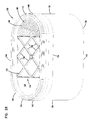
- FIG. 23 is a schematic, perspective view of a portion of filter media (Z-media) useable in the arrangement of FIG. 22;
- FIG. 24 is a schematic, cross-sectional view of the filter element depicted in FIG. 22 installed within a housing;
- FIG. 25 is a fragmented, enlarged, schematic view of one embodiment of a compressible seal member utilized in a sealing system for the filter element of FIG. 22;
- FIG. 26 is a schematic, perspective view of another embodiment of a filter element that may be utilized in the engine system of FIG. 21;
- FIG. 27 is a schematic, cross-sectional view of the filter element of FIG. 26 installed within a housing;
- FIG. 28 is a schematic, exploded, perspective view of another embodiment of a filter element and housing that may be utilized in the engine system of FIG. 21;
- FIG. 29 is a schematic depiction of a gas turbine system in which filter elements according to the present disclosure may be utilized
- FIG. 30 is a schematic, perspective view of one embodiment of a filter element that may be useable in gas turbine air intake systems depicted in FIG. 29;
- FIG. 31 is a rear elevational view of the filter element depicted in FIG. 30 installed within a tube sheet, and having a prefilter installed upstream of the filter element of FIG. 30;
- FIG. 32 is an enlarged, schematic, fragmented, cross-sectional view of the air filter arrangement of FIG. 31, taken along the line 12 — 12 of FIG. 31;
- FIG. 33 is a schematic view of an air intake system for a microturbine system, in which filter elements of the present disclosure may be utilized;
- FIG. 34 is a schematic, cross-sectional view of a filter element in an operable installation to clean intake air in a gas turbine system, the cross-section being taken along the line 14 — 14 of FIG. 35, but in an assembled state;
- FIG. 35 is an exploded, side elevational view of the filter arrangement of FIG. 34, and in an unassembled state;
- FIG. 36 is a fragmented, schematic, cross-sectional view showing the filter element sealed within a filter housing
- FIG. 37 is a schematic view of an air intake for a fuel cell system, which may utilize filter elements disclosed herein;
- FIG. 38 is a schematic, cross-sectional view of a filter assembly that may be utilized in the fuel cell air intake system of FIG. 37;
- FIG. 39 is a schematic, cross-sectional view of another embodiment of a filter assembly that may be utilized in the air intake for a fuel cell system.
- the invention provides an improved polymeric material.
- This polymer has improved physical and chemical stability.
- the polymer fine fiber (microfiber and nanofiber) can be fashioned into useful product formats.
- the fiber can have a diameter of about 0.001 to 10 microns, about 0.005 to 5 microns, about 0.01 to 0.5 micron.
- Nanofiber is a fiber with diameter less than 200 nanometer or 0.2 micron.
- Microfiber is a fiber with diameter larger than 0.2 micron, but not larger than 10 microns.
- This fine fiber can be made in the form of an improved multi-layer microfiltration media structure.
- the fine fiber layers of the invention comprise a random distribution of fine fibers which can be bonded to form an interlocking net. Filtration performance is obtained largely as a result of the fine fiber barrier to the passage of particulate. Structural properties of stiffness, strength, pleatability are provided by the substrate to which the fine fiber adhered.
- the fine fiber interlocking networks have as important characteristics, fine fibers in the form of microfibers or nanofibers and relatively small spaces between the fibers. Such interfiber spaces in the layer typically range, between fibers, of about 0.01 to about 25 microns or often about 0.1 to about 10 microns.
- the filter products comprise a fine fiber layer on a choice of appropriate substrate such as a synthetic layer, a natural layer or a mixed natural/synthetic substrate.
- the fine fiber adds less than 5 microns, often less than 3 microns of thickness.
- the fine fiber in certain applications adds about 1 to 10 or 1 to 5 fine fiber diameters in thickness to the overall fine fiber plus substrate filter media.
- the filters can stop incident particulate from passing to the substrate or through the fine fiber layer and can attain substantial surface loadings of trapped particles.
- the particles comprising dust or other incident particulates rapidly form a dust cake on the fine fiber surface and maintains high initial and overall efficiency of particulate removal.
- Even with relatively fine contaminants having a particle size of about 0.01 to about 1 micron, the filter media comprising the fine fiber has a very high dust capacity.
- the polymer materials as disclosed herein have substantially improved resistance to the undesirable effects of heat, humidity, high flow rates, reverse pulse cleaning, operational abrasion, submicron particulates, cleaning of filters in use and other demanding conditions.
- the improved microfiber and nanofiber performance is a result of the improved character of the polymeric materials forming the microfiber or nanofiber.
- the filter media of the invention using the improved polymeric materials of the invention provides a number of advantageous features including higher efficiency, lower flow restriction, high durability (stress related or environmentally related) in the presence of abrasive particulates and a smooth outer surface free of loose fibers or fibrils.
- the overall structure of the filter materials provides an overall thinner media allowing improved media area per unit volume, reduced velocity through the media, improved media efficiency and reduced flow restrictions.
- the polymer can be an additive polymer, a condensation polymer or mixtures or blends thereof.
- a preferred mode of the invention is a polymer blend comprising a first polymer and a second, but different polymer (differing in polymer type, molecular weight or physical property) that is conditioned or treated at elevated temperature.
- the polymer blend can be reacted and formed into a single chemical specie or can be physically combined into a blended composition by an annealing process. Annealing implies a physical change, like crystallinity, stress relaxation or orientation.
- Preferred materials are chemically reacted into a single polymeric specie such that a Differential Scanning Calorimeter analysis reveals a single polymeric material.
- Such a material when combined with a preferred additive material, can form a surface coating of the additive on the microfiber that provides oleophobicity, hydrophobicity or other associated improved stability when contacted with high temperature, high humidity and difficult operating conditions.
- the fine fiber of the class of materials can have a diameter of 0.001 micron to 10 microns. Useful sizes include 0.001 to 2 microns, 0.005 to 5 microns, 0.01 to 5 microns, depending on bonding, substrate and application.
- Such microfibers can have a smooth surface comprising a discrete layer of the additive material or an outer coating of the additive material that is partly solubilized or alloyed in the polymer surface, or both.
- Preferred materials for use in the blended polymeric systems include nylon 6; nylon 66; nylon 6-10; nylon (6-66-610) copolymers and other linear generally aliphatic nylon compositions.
- a preferred nylon copolymer resin SVP-651 was analyzed for molecular weight by the end group titration. (J. E. Walz and G. B. Taylor, determination of the molecular weight of nylon, Anal. Chem. Vol. 19, Number 7, pp 448-450 (1947). A number average molecular weight (M n ) was between 21,500 and 24,800.
- the composition was estimated by the phase diagram of melt temperature of three component nylon, nylon 6 about 45%, nylon 66 about 20% and nylon 610 about 25%. (Page 286, Nylon Plastics Handbook, Melvin Kohan ed. Hanser Publisher, New York (1995)).
- a polyvinylalcohol having a hydrolysis degree of from 87 to 99.9+% can be used in such polymer systems. These are preferably cross linked. And they are most preferably crosslinked and combined with substantial quantities of the oleophobic and hydrophobic additive materials.
- Another preferred mode of the invention involves a single polymeric material combined with an additive composition to improve fiber lifetime or operational properties.
- the preferred polymers useful in this aspect of the invention include nylon polymers, polyvinylidene chloride polymers, polyvinylidene fluoride polymers, polyvinylalcohol polymers and, in particular, those listed materials when combined with strongly oleophobic and hydrophobic additives that can result in a microfiber or nanofiber with the additive materials formed in a coating on the fine fiber surface.
- blends of similar polymers such as a blend of similar nylons, similar polyvinylchloride polymers, blends of polyvinylidene chloride polymers are useful in this invention.
- polymeric blends or alloys of differing polymers are also contemplated by the invention.
- compatible mixtures of polymers are useful in forming the microfiber materials of the invention.
- Additive composition such a fluoro-surfactant, a nonionic surfactant, low molecular weight resins (e.g.) tertiary butylphenol resin having a molecular weight of less than about 3000 can be used.
- the resin is characterized by oligomeric bonding between phenol nuclei in the absence of methylene bridging groups. The positions of the hydroxyl and the tertiary butyl group can be randomly positioned around the rings. Bonding between phenolic nuclei always occurs next to hydroxyl group, not randomly.
- the polymeric material can be combined with an alcohol soluble non-linear polymerized resin formed from bis-phenol A.
- an alcohol soluble non-linear polymerized resin formed from bis-phenol A.
- Such material is similar to the tertiary butylphenol resin described above in that it is formed using oligomeric bonds that directly connect aromatic ring to aromatic ring in the absence of any bridging groups such as alkylene or methylene groups.
- Preferred polymer systems of the invention have adhering characteristic such that when contacted with a cellulosic substrate adheres to the substrate with sufficient strength such that it is securely bonded to the substrate and can resist the delaminating effects of a reverse pulse cleaning technique and other mechanical stresses.
- the polymer material In such a mode, the polymer material must stay attached to the substrate while undergoing a pulse clean input that is substantially equal to the typical filtration conditions except in a reverse direction across the filter structure.
- Such adhesion can arise from solvent effects of fiber formation as the fiber is contacted with the substrate or the post treatment of the fiber on the substrate with heat or pressure.
- polymer characteristics appear to play an important role in determining adhesion, such as specific chemical interactions like hydrogen bonding, contact between polymer and substrate occurring above or below Tg, and the polymer formulation including additives.
- Polymers plasticized with solvent or steam at the time of adhesion can have increased adhesion.
- An important aspect of the invention is the utility of such microfiber or nanofiber materials formed into a filter structure.
- the fine fiber materials of the invention are formed on and adhered to a filter substrate.
- Natural fiber and synthetic fiber substrates like spun bonded fabrics, non-woven fabrics of synthetic fiber and non-wovens made from the blends of cellulosics, synthetic and glass fibers, non-woven and woven glass fabrics, plastic screen like materials both extruded and hole punched, UF and MF membranes of organic polymers can be used.
- Sheet-like substrate or cellulosic non-woven web can then be formed into a filter structure that is placed in a fluid stream including an air stream or liquid stream for the purpose of removing suspended or entrained particulate from that stream.
- the shape and structure of the filter material is up to the design engineer.
- One important parameter of the filter elements after formation is its resistance to the effects of heat, humidity or both.
- One aspect of the filter media of the invention is a test of the ability of the filter media to survive immersion in warm water for a significant period of time. The immersion test can provide valuable information regarding the ability of the fine fiber to survive hot humid conditions and to survive the cleaning of the filter element in aqueous solutions that can contain substantial proportions of strong cleaning surfactants and strong alkalinity materials.
- the fine fiber materials of the invention can survive immersion in hot water while retaining at least 30%, preferably 50% of the fine fiber formed on the surface of the substrate.
- Retention of at least 30%, preferably 50% of the fine fiber can maintain substantial fiber efficiency without loss of filtration capacity or increased back pressure. Most preferably retaining at least 75%.
- the thickness of the typical fine fiber filtration layer ranges from about 1 to 100 times the fiber diameter with a basis weight ranging from about 0.01 to 240 micrograms-cm ⁇ 2 .
- Fluid streams such as air and gas streams often carry particulate material therein.
- the removal of some or all of the particulate material from the fluid stream is needed.
- air intake streams to the cabins of motorized vehicles, air in computer disk drives, HVAC air, aircraft cabin ventilation, clean room ventilation and applications using filter bags, barrier fabrics, woven materials, air to engines for motorized vehicles, or to power generation equipment; gas streams directed to gas turbines; and, air streams to various combustion furnaces often include particulate material therein.
- cabin air filters it is desirable to remove the particulate matter for comfort of the passengers and/or for aesthetics.
- production gases or off gases from industrial processes or engines may contain particulate material therein. Before such gases can be, or should be, discharged through various downstream equipment to the atmosphere, it may be desirable to obtain a substantial removal of particulate material from those streams.
- the “lifetime” of a filter is typically defined according to a selected limiting pressure drop across the filter.
- the pressure buildup across the filter defines the lifetime at a defined level for that application or design. Since this buildup of pressure is a result of load, for systems of equal efficiency a longer life is typically directly associated with higher capacity. Efficiency is the propensity of the media to trap, rather than pass, particulates. It should be apparent that typically the more efficient a filter media is at removing particulates from a gas flow stream, in general the more rapidly the filter media will approach the “lifetime” pressure differential (assuming other variables to be held constant).
- the microfiber or nanofiber of the unit can be formed by the electrostatic spinning process.
- a suitable apparatus for forming the fiber is illustrated in FIG. 1 .
- This apparatus includes a reservoir 80 in which the fine fiber forming polymer solution is contained, a pump 81 and a rotary type emitting device or emitter 40 to which the polymeric solution is pumped.
- the emitter 40 generally consists of a rotating union 41 , a rotating portion 42 including a plurality of offset holes 44 and a shaft 43 connecting the forward facing portion and the rotating union.
- the rotating union 41 provides for introduction of the polymer solution to the forward facing portion 42 through the hollow shaft 43 .
- the holes 44 are spaced around the periphery of the forward facing portion 42 .
- the rotating portion 42 can be immersed into a reservoir of polymer fed by reservoir 80 and pump 81 .
- the rotating portion 42 then obtains polymer solution from the reservoir and as it rotates in the electrostatic field, a droplet of the solution is accelerated by the electrostatic field toward the collecting media 70 as discussed below.
- a substantially planar grid 60 Facing the emitter 40 , but spaced apart therefrom, is a substantially planar grid 60 upon which the collecting media 70 (i.e. substrate or combined substrate is positioned. Air can be drawn through the grid.
- the collecting media 70 is passed around rollers 71 and 72 which are positioned adjacent opposite ends of grid 60 .
- a high voltage electrostatic potential is maintained between emitter 40 and grid 60 by means of a suitable electrostatic voltage source 61 and connections 62 and 63 which connect respectively to the grid 60 and emitter 40 .
- the polymer solution is pumped to the rotating union 41 or reservoir from reservoir 80 .
- the forward facing portion 42 rotates while liquid exits from holes 44 , or is picked up from a reservoir, and moves from the outer edge of the emitter toward collecting media 70 positioned on grid 60 .
- the electrostatic potential between grid 60 and the emitter 40 imparts a charge to the material which cause liquid to be emitted therefrom as thin fibers which are drawn toward grid 60 where they arrive and are collected on substrate 12 or an efficiency layer 14 .
- solvent is evaporated off the fibers during their flight to the grid 60 ; therefore, the fibers arrive at the substrate 12 or efficiency layer 14 .
- the fine fibers bond to the substrate fibers first encountered at the grid 60 .
- Electrostatic field strength is selected to ensure that the polymer material as it is accelerated from the emitter to the collecting media 70 , the acceleration is sufficient to render the material into a very thin microfiber or nanofiber structure.
- Increasing or slowing the advance rate of the collecting media can deposit more or less emitted fibers on the forming media, thereby allowing control of the thickness of each layer deposited thereon.
- the rotating portion 42 can have a variety of beneficial positions.
- the rotating portion 42 can be placed in a plane of rotation such that the plane is perpendicular to the surface of the collecting media 70 or positioned at any arbitrary angle.
- the rotating media can be positioned parallel to or slightly offset from parallel orientation.
- FIG. 2 is a general schematic diagram of a process and apparatus for forming a layer of fine fiber on a sheet-like substrate or media.
- the sheet-like substrate is unwound at station 20 .
- the sheet-like substrate 20 a is then directed to a splicing station 21 wherein multiple lengths of the substrate can be spliced for continuous operation.
- the continuous length of sheet-like substrate is directed to a fine fiber technology station 22 comprising the spinning technology of FIG. 1 wherein a spinning device forms the fine fiber and lays the fine fiber in a filtering layer on the sheet-like substrate.
- the fine fiber layer and substrate are directed to a heat treatment station 23 for appropriate processing.
- the sheet-like substrate and fine fiber layer is then tested in an efficiency monitor 24 and nipped if necessary at a nip station 25 .
- the sheet-like substrate and fiber layer is then steered to the appropriate winding station to be wound onto the appropriate spindle for further processing 26 and 27 .
- FIG. 3 is a scanning electromicrograph image showing the relationship of typical dust particles having a diameter of about 2 and about 5 microns with respect to the sizes of pores in typical cellulose media and in the typical fine fiber structures.
- the 2 micron particle 31 and the 5 micron particle 32 is shown in a cellulosic media 33 with pore sizes that are shown to be quite a bit larger than the typical particle diameters.
- the 2 micron particle 31 appears to be approximately equal to or greater than the typical openings between the fibers in the fiber web 35 while the 5 micron particle 32 appears to be larger than any of the openings in the fine fiber web 35 .
- the fine fiber materials of the invention including both microfibers and nanofibers and the construction of useful filter structures from the fine fiber materials of the invention provides an understanding of the general technological principles of the operation of the invention.
- the following specific exemplary materials are examples of materials that can be used in the formation of the fine fiber materials of the invention and the following materials disclose a best mode.
- the following exemplary materials were manufactured with the following characteristics and process conditions in mind. Electrospinning small diameter fiber less than 10 micron is obtained using an electrostatic force from a strong electric field acting as a pulling force to stretch a polymer jet into a very fine filament.
- a polymer melt can be used in the electrospinning process, however, fibers smaller than 1 micron are best made from polymer solution.
- solvent evaporates and contributes to the reduction of fiber size.
- Choice of solvent is critical for several reasons. If solvent dries too quickly, then fibers tends to be flat and large in diameter. If the solvent dries too slowly, solvent will redissolve the formed fibers. Therefore matching drying rate and fiber formation is critical.
- large quantities of exhaust air flow helps to prevent a flammable atmosphere, and to reduce the risk of fire.
- a solvent that is not combustible is helpful. In a production environment the processing equipment will require occasional cleaning. Safe low toxicity solvents minimize worker exposure to hazardous chemicals.
- Electrostatic spinning can be done at a flow rate of 1.5 ml/min per emitter, a target distance of 8 inches, an emitter voltage of 88 kV, an emitter rpm of 200 and a relative humidity of 45%.
- microfiber can help to minimize pressure loss and provide an outer surface for particle capture and release.
- Good adhesion between microfiber or nanofiber and substrates upon which the microfibers or nanofibers are deposited is important.
- filters are made of composites of substrate and thin layer of micro- and nanofibers, such composite makes an excellent filter medium for self-cleaning application. Cleaning the surface by back pulsing repeatedly rejuvenates the filter medium.
- Products that meet the above requirements can be obtained using fibers made from different polymer materials.
- Small fibers with good adhesion properties can be made from such polymers like polyvinylidene chloride, poly vinyl alcohol and polymers and copolymers comprising various nylons such as nylon 6, nylon 4, 6; nylon 6, 6; nylon 6, 10 and copolymers thereof.
- Excellent fibers can be made from PVDF, but to make sufficiently small fiber diameters requires chlorinated solvents.
- Nylon 6, Nylon 66 and Nylon 6, 10 can be electrospun. But, solvents such as formic acid, m-cresol, tri-fluoro ethanol, hexafluoro isopropanol are either difficult to handle or very expensive.
- Preferred solvents include water, ethanol, isopropanol, acetone and N-methyl pyrrolidone due to their low toxicity.
- Polymers compatible with such solvent systems have been extensively evaluated. We have found that fibers made from PVC, PVDC, polystyrene, polyacrylonitrile, PMMA, PVDF require additional adhesion means to attain structural properties. We also found that when polymers are dissolved in water, ethanol, isopropanol, acetone, methanol and mixtures thereof and successfully made into fibers, they have excellent adhesion to the substrate, thereby making an excellent filter medium for self-cleaning application. Self-cleaning via back air pulse or twist is useful when filer medium is used for very high dust concentration.
- Alcohol soluble polyamides Fibers from alcohol soluble polyamides and poly(vinyl alcohol)s have been used successfully in such applications.
- alcohol soluble polyamides include Macromelt 6238, 6239, and 6900 from Henkel, Elvamide 8061 and 8063 from duPont and SVP 637 and 651 from Shakespeare Monofilament Company.
- Another group of alcohol soluble polyamide is type 8 nylon, alkoxy alkyl modifies nylon 66 (Ref. Page 447, Nylon Plastics handbook, Melvin Kohan ed. Hanser Publisher, New York, 1995).
- poly(vinyl alcohol) include PVA-217, 224 from Kuraray, Japan and Vinol 540 from Air Products and Chemical Company.
- filters can be exposed to extremes in environmental conditions. Filters in Saudi Arabian desert can be exposed to temperature as high as 150 F.° or higher. Filters installed in Indonesia or Gulf Coast of US can be exposed high humidity above 90% RH and high temperature of 100 F.°. Or, they can be exposed to rain. We have found that filters used under the hood of mobile equipment like cars, trucks, buses, tractors, and construction equipment can be exposed to high temperature (+200° F.), high relative humidity and other chemical environment. We have developed test methods to evaluate survivability of microfiber systems under harsh conditions. Soaking the filter media samples in hot water (140 F.°) for 5 minutes or exposure to high humidity, high temperature and air flow.
- air cleaner will be used in reference to a system which functions to remove particulate material from an air flow stream.
- air filter references a system in which removal is conducted by passage of the air, carrying particulate therein, through filter media.
- filter media or “media” refers to a material or collection of material through which the air passes, with a concomitant deposition of the particles in or on the media.
- surface loading media or “barrier media” refers to a system in which as the air passes through the media, the particulate material is primarily deposited on the surface of the media, forming a filter cake, as opposed to into or through the depth of the media.
- filter element is generally meant to refer to a portion of the air cleaner which includes the filter media therein.
- a filter element will be designed as a removable and replaceable, i.e. serviceable, portion of the air cleaner. That is, the filter media will be carried by the filter element and be separable from the remainder portion of the air cleaner so that periodically the air cleaner can be rejuvenated by removing a loaded or partially loaded filter element and replacing it with a new, or cleaned, filter element.
- the air cleaner is designed so that the removal and replacement can be conducted by hand.
- loaded or variants thereof in this context, reference is meant to an air cleaner which has been on-line a sufficient period of time to contain a significant amount of trapped particles or particulates thereon.
- a filter element will increase in weight, due to particulate loading therein, of two or three times (or more) its original weight.
- specifications for the performance of an air cleaner system are, generated by the preferences of the original equipment manufacturer (OEM) for the engine involved and/or the OEM of the truck or other equipment involved. While a wide variety of specifications may be involved, some of the major ones are the following:
- the engine air intake need is a function of the engine size, i.e. displacement and rpm at maximum, full or “rated” load. In general, it is the product of displacement and rated rpm, modified by the volumetric efficiency, a factor which reflects turbo efficiency, duct efficiency, etc. In general, it is a measurement of the volume of air, per unit time, required by the engine or other system involved, during rated operation or full load. While air intake need will vary depending upon rpm, the air intake requirement is defined at a rated rpm, often at 1800 rpm or 2100 rpm for many typical truck engines. Herein this will be characterized as the “rated air flow” or by similar terms.
- Such equipment includes, for example: small utility engines (motorcycles, lawn mowers, etc.), automotive engines, pickup trucks and sport utility vehicle engines, engines for small trucks and delivery vehicles, buses, over-the-highway trucks, agricultural equipment (for example tractors), construction equipment, mining equipment, marine engines, a variety of generator engines, and, in some instances, gas turbines and air compressors.
- Air cleaner overall efficiency is generally a reflection of the amount of “filterable” solids which pass into the air cleaner during use, and which are retained by the air cleaner. It is typically represented as the percentage of solids passing into the air cleaner which are retained by the air cleaner in normal use, on a weight basis. It is evaluated and reported for many systems by using SAE standards, which techniques are generally characterized in U.S. Pat. No. 5,423,892 at Column 25, line 60-Column 26, line 59; Column 27, lines 1-40. A typical standard used is SAE J726, incorporated herein by reference.
- Initial efficiency is the measurable efficiency of the filter when it is first put on line. As explained in U.S. Pat. No. 5,423,892 at Column 27, lines 1-40, especially with conventional pleated paper (barrier type or surface-loading) filters, initial efficiency is generally substantially lower than the overall average efficiency during use. This is because the “dust cake” or contaminant build-up on the surface of such a filter during operation, increases the efficiency of the filter. Initial efficiency is also often specified by the engine manufacturer and/or the vehicle manufacturer. With typical vehicle engines having air flow demands of 500 cfm or above, specifications of 98% or above (typically 98.5% or above) are common.
- Restriction is the pressure differential across an air cleaner or air cleaner system during operation.
- Contributors to the restriction include: the filter media through which the air is directed; duct size through which the air is directed; and, structural features against which or around which the air is directed as it flows through the air cleaner and into the engine.
- initial restriction limits are often part of the specifications and demands of the engine manufacturer and/or equipment manufacturer. This initial restriction would be the pressure differential measured across the air cleaner when the system is put on line with a clean air filter therein and before significant loading occurs. Typically, the specifications for any given system have a maximum initial restriction requirement.
- conventional cellulose fiber media or similar media is generally a “barrier” filter.
- An example is paper media.
- the operation of such media is through surface loading, i.e., when air is directed through the media, the surface of the media acts as a barrier or sieve, preventing passage of particulate material therethrough.
- a dust cake builds on the surface of the media, increasing media efficiency.
- the “tightness” or “porosity” of the fiber construction determines the efficiency, especially the initial efficiency, of the system. In time, the filter cake will effect (increase) the efficiency.
- Such media is often defined or specified by its permeability.
- the permeability test for media is generally characterized in U.S. Pat. No. 5,672,399 at Col. 19, lines 27-39. In general, it is the media face velocity (air) required to induce a 0.50 inch water restriction across a flat sheet of the referenced material, media or composite.
- Permeability is assessed by a Frazier Perm Test, according to ASTM D737 incorporated herein by reference, for example using a Frazier Perm Tester available from Frazier Precision Instrument Co., Inc., Gaithersburg, Md., or by some analogous test.
- the permeability of cellulose fiber media used in many types of engine filters for trucks having rated air flows of 50 cfm or more manufactured by Donaldson Company is media having a permeability of less than about 15 fpm, typically around 13 fpm.
- barrier media pleated media having permeability values of less than about 25 fpm, and typically somewhere within the range of 10-25 fpm, have been widely utilized by various element manufacturers.
- cellulose fiber or similar barrier media is generally varied, with respect to efficiency, by varying overall general porosity or permeability.
- FIG. 21 a schematic view of a system is shown generally at 130 .
- System 130 is one example type of system in which air cleaner arrangements and constructions described herein is usable.
- equipment 131 such as a vehicle, having an engine 132 with some defined rated air flow demand, for example, at least 370 cfm, is shown schematically.
- Equipment 131 may comprise a bus, an over the highway truck, an off-road vehicle, a tractor, or marine application such as a power boat.
- Engine 132 powers equipment 131 , through use of an air, fuel mixture.
- air flow is shown drawn into engine 132 at an intake region 133 .
- An optional turbo 134 is shown in phantom, as optionally boosting the air intake into the engine 132 .
- An air cleaner 135 having a media pack 136 is upstream of the engine 132 and turbo 134 .
- air is drawn in at arrow 137 into the air cleaner 135 and through media pack 136 .
- particles and contaminants are removed from the air.
- the cleaned air flows at arrow 137 into the intake 133 . From there, the air flows into engine 132 , to power vehicle 131 .
- the temperature, under the hood typically is at least 120° F., and often is in the range of 140° F.-220° F. or more depending on operating conditions.
- the temperature may adversely affect the operating efficiency of the filter element. Regulations on emissions can increase the restriction on the engine exhaust, causing further increased temperatures.
- constructing the filter media in the form of a composite of a barrier media and at least a single layer, and in some instances, multiple layers of “fine fiber” can improve the performance (the operating efficiency, in particular) of the filter element over prior art filter elements that are not constructed from such media composites.
- FIG. 22 is a perspective view of a first embodiment of a media pack 140 .
- the preferred media pack 140 depicted includes filter media 142 and a sealing system 144 .
- the filter media 142 is designed to remove particulates from a fluid, such as air, passing through the filter media 142
- the sealing system 144 is designed to seal the media pack 140 against a sidewall of a housing or duct, as shown in FIG. 24 .
- This media pack 140 of FIGS. 22-25 is generally described in U.S. Pat. No. 6,190,432, which is incorporated by reference herein.
- the filter media 142 will be configured for straight-through flow.
- straight-through flow it is meant that the filter media 142 is configured in a construction 146 with a first flow face 148 (corresponding to an inlet end, in the illustrated embodiment) and an opposite, second flow face 150 (corresponding to an outlet end, in the illustrated embodiment), with fluid flow entering in one direction 152 through the first flow face 148 and exiting in the same direction 154 from the second flow face 150 .
- the fluid When used with an inline-flow housing, in general, the fluid will enter through the inlet of the housing in one direction, enter the filter construction 146 through the first flow face 148 in the same direction, exit the filter construction 146 in the same direction from the second flow face 150 , and exit the housing through the housing outlet also in the same direction.
- first flow face 148 and the second flow face 150 are depicted as planar and as parallel. In other embodiments, the first flow face 148 and the second flow face 150 can be non-planar, for example, frusto-conical. Further, the first flow face 148 and second flow face 150 need not be parallel to each other.
- the filter construction 146 will be a wound construction. That is, the construction 146 will typically include a layer of filter media that is turned completely or repeatedly about a center point. Typically, the wound construction will be a coil, in that a layer of filter media will be rolled a series of turns around a center point. In arrangements where a wound, coiled construction is used, the filter construction 146 will be a roll of filter media, typically permeable fluted filter media.
- FIG. 23 is schematic, perspective view demonstrating the principles of operation of certain preferred media usable in the filter constructions herein.
- a fluted construction of Z-media is generally designated at 156 .
- the fluted construction 156 includes: a layer 157 of corrugations having a plurality of flutes 158 and a face sheet 160 .
- the FIG. 22 embodiment shows two sections of the face sheet 160 , at 160 A (depicted on top of the corrugated layer 157 ) and at 160 B (depicted below the corrugated layer 157 ).
- the preferred media construction 162 used in arrangements described herein will include the corrugated layer 157 secured to the bottom face sheet 160 B.
- this media construction 162 When using this media construction 162 in a rolled construction, it typically will be wound around itself, such that the bottom face sheet 160 B will cover the top of the corrugated layer 157 .
- the face sheet 160 covering the top of the corrugated layer is depicted as 160 A. It should be understood that the face sheet 160 A and 160 B are the same sheet 160 .
- the flute chambers 158 When using this type of media construction 162 , the flute chambers 158 preferably form alternating peaks 164 and troughs 166 .
- the troughs 166 and peaks 164 divide the flutes into an upper row and lower row.
- the upper flutes form flute chambers 168 closed at the downstream end 178
- flute chambers 170 having their upstream end 181 closed form the lower row of flutes.
- the fluted chambers 170 are closed by a first end bead 172 that fills a portion of the upstream end 181 of the flute between the fluting sheet 171 and the second facing sheet 160 B.
- a second end bead 174 closes the downstream end 178 of alternating flutes 168 .
- unfiltered fluid such as air
- the flute chambers 168 have their upstream ends 169 open.
- the unfiltered fluid flow is not permitted to pass through the downstream ends 178 of the flute chambers 168 because their downstream ends 178 are closed by the second end bead 174 . Therefore, the fluid is forced to proceed through the fluting sheet 171 or face sheets 160 .
- the unfiltered fluid passes through the fluting sheet 171 or face sheets 160 , the fluid is cleaned or filtered. The cleaned fluid is indicated by the unshaded arrow 180 .
- the fluid then passes through the flute chambers 170 (which have their upstream ends 181 closed) to flow through the open downstream end 184 out the fluted construction 156 .
- the unfiltered fluid can flow through the fluted sheet 171 , the upper facing sheet 160 A, or lower facing sheet 160 B, and into a flute chamber 170 .
- the media construction 162 will be prepared and then wound to form a rolled construction 146 of filter media.
- the media construction 162 prepared includes the sheet of corrugations 157 secured with the end bead 172 to the bottom face sheet 160 B (as shown in FIG. 23, but without the top face sheet 160 A).
- FIG. 22 Attention is again directed to FIG. 22 .
- the second flow face 150 is shown schematically. There is a portion at 182 in which the flutes including the open ends 184 and closed ends 178 are depicted. It should be understood that this section 182 is representative of the entire flow face 50 . For the sake of clarity and simplicity, the flutes are not depicted in the other remaining portions 183 of the flow face 150 .
- Top and bottom plan views, as well as side elevational views of a media pack 140 usable in the systems and arrangements described herein are depicted in copending and commonly assigned U.S. patent application Ser. No. 29/101,193, filed Feb. 26, 1999, and entitled, “Filter Element Having Sealing System,” herein incorporated by reference.
- the filter construction 146 is shown installed in a housing 186 (which can be part of an air intake duct into an engine or turbo of an air cleaner 179 ). In the arrangement shown, air flows into the housing 186 at 187 , through the filter construction 146 , and out of the housing 186 at 188 .
- the sealing system 144 will be needed to ensure that air flows through the media construction 146 , rather than bypass it.
- the particular sealing system 144 depicted includes a frame construction 190 and a seal member 192 .
- the frame construction 190 provides a support structure or backing against which the seal member 192 can be compressed against to form a radial seal 194 with the duct or housing 186 .
- the frame construction 190 includes a rigid projection 196 that projects or extends from at least a portion of one of the first and second flow faces 148 , 150 of the filter construction 146 .
- the rigid projection 196 in the particular arrangement shown in FIG. 24, extends axially from the second flow face 150 of the filter construction 146 .
- the projection 196 shown has a pair of opposite sides 198 , 102 joined by an end tip 104 .
- one of the first and second sides 198 , 102 will provide a support or backing to the seal member 192 such that seal 194 can be formed between and against the selected side 198 or 102 and the appropriate surface of the housing or duct.
- the projection 196 will be a continuous member forming a closed hoop structure 106 (FIG. 22 ).
- a housing or duct may circumscribe the projection 196 and hoop structure 106 including the seal member 192 to form seal 194 between and against the outer side 102 of the projection 196 and an inner surface 110 of the housing or duct.
- the seal member 192 engages the end tip 104 of the projection 196 as well, such that the seal member 192 covers the projection 196 from the exterior side 102 , over the end tip 104 , and to the interior side 198 .
- the frame 190 has a band, skirt, or depending lip 107 that is used to secure the frame 190 to the media construction 146 .
- the depending lip 107 depends or extends down a first distance from cross braces 108 .
- Cross braces 108 support the frame 190 .
- support it is meant that the cross braces 108 prevent the frame 190 from radially collapsing under the forces exerted around the circumference of the frame 190 .
- the tip portion 104 provides support for the compressible seal member 192 .
- the compressible seal member 192 is preferably constructed and arranged to be sufficiently compressible to be compressed between the tip portion 104 of the frame 190 and sidewall 110 of a housing or duct. When sufficiently compressed between the tip portion 104 and the sidewall 110 , radial seal 194 is formed between the media pack 140 and the sidewall 110 .
- seal member 192 is shown in FIG. 25 .
- the tip portion 104 of the frame 190 defines a wall or support structure between and against which radial seal 194 may be formed by the compressible seal member 192 .
- the compression of the compressible seal member 192 at the sealing system 144 is preferably sufficient to form a radial seal under insertion pressures of no greater than 80 lbs., typically, no greater than 50 lbs., for example, about 20-40 lbs., and light enough to permit convenient and easy change out by hand.
- the seal member 192 is a stepped cross-sectional configuration of decreasing outermost dimensions (diameter, when circular) from a first end 112 to a second end 113 , to achieve desirable sealing.
- Preferred specifications for the profile of the particular arrangement shown in FIG. 25 are as follows: a polyurethane foam material having a plurality of (preferably at least three) progressively larger steps configured to interface with the sidewall 110 and provide a fluid-tight seal.
- the compressible seal member 192 defines a gradient of increasing internal diameters of surfaces for interfacing with the sidewall 110 . Specifically, in the example shown in FIG. 25, the compressible seal member 192 defines three steps 114 , 115 , 116 . The cross-sectional dimension or width of the steps 114 , 115 , 116 increases the further the step 114 , 115 , 116 is from the second end 113 of the compressible seal member 192 . The smaller diameter at the second end 113 allows for easy insertion into a duct or housing. The larger diameter at the first end 112 ensures a tight seal.
- the media pack 140 can be arranged and configured to be press-fit against the sidewall 110 of the housing 186 or duct.
- the compressible seal member 192 is compressed between the sidewall 110 and the tip portion 104 of the frame 190 . After compression, the compressible seal member 192 exerts a force against the sidewall 110 as the compressible seal member 192 tries to expand outwardly to its natural state, forming radial seal 94 between and against the tip portion 104 and the sidewall 110 .
- the housing 186 includes a body member or a first housing compartment 118 and a removable cover or second housing compartment 120 .
- the first housing compartment 118 is affixed to an object, such as a truck.
- the second housing compartment 120 is removably secured to the first housing compartment 118 by a latching device 122 .
- the second end 150 of the media pack 140 with the attached frame 190 and compressible seal member 192 is inserted into the first housing compartment 118 .
- the media pack 140 is press-fit into the first housing compartment 118 such that the compressible seal member 192 is compressed between and against the tip portion 104 of the frame 190 and the sidewall 110 of the first housing compartment 118 , to form radial seal 194 therebetween.
- the fluid enters the housing assembly 185 at the inlet region 124 of the second housing compartment 120 , in the direction shown at 187 .
- the fluid passes through the filter construction 146 .
- contaminants are removed from the fluid.
- the fluid exits the housing assembly 185 at the outlet region 128 , in the direction of 188 .
- the compressible seal member 192 of the sealing system 144 forms radial seal 194 to prevent contaminated fluid from exiting the housing assembly 185 , without first passing through the filter construction 146 .
- FIG. 26 is a perspective view of another embodiment of a media pack 130 .
- the media pack 130 includes filter media 132 and a sealing system 134 .
- the filter media 132 is designed to remove contaminants from a fluid, such as air, passing through the filter media 132 .
- the sealing system 134 is designed to seal the filter media 134 to a housing or duct.
- the filter media 132 will be configured in a filter construction 136 with a first flow face 138 and an opposite, second flow face 140 .
- the filter construction 136 can have a variety of configurations and cross-sectional shapes. In the particular embodiment illustrated in FIG. 26, the filter construction 136 has a non-circular cross-section. In particular, the FIG. 26 embodiment of the filter construction 136 has an ob-round or “racetrack” cross-sectional shape. By “racetrack” cross-sectional shape, it is meant that the filter construction 136 includes first and second semicircular ends 141 , 142 joined by a pair of straight segments 143 , 144 .
- FIG. 26 certain portions 146 are depicted showing the flutes, including the open and closed ends. It should be understood that this portion or section 146 is representative of the entire flow face 140 (as well as the first flow face 138 ). For the sake of clarity and simplicity, the flutes are not depicted in the other remaining portions 149 of the flow face 140 .
- Top and bottom plan views, as well as side elevational views of the media pack 130 usable in the systems and arrangements described herein are depicted in copending and commonly assigned U.S. patent application Ser. No. 29/101,193, filed Feb. 26, 1999, and entitled, “Filter Element Having Sealing System,” herein and incorporated by reference.
- the media pack 130 includes sealing system 134 .
- the sealing system 134 includes a frame 148 and a seal member 150 .
- the frame 148 has a non-circular, for example, obround and in particular, a racetrack shape and is arranged and configured for attachment to the end of the filter media 132 .
- the frame 148 has a band or skirt or depending lip 151 that is generally racetrack shaped.
- the depending lip 151 depends or extends down a distance from cross braces 152 and is used to secure the frame 148 to the media pack 130 .
- inward forces are exerted around the circumference of the frame 148 .
- Inward forces exerted against the semicircular ends 141 , 142 can cause the straight segments 143 , 144 to bow or bend.
- Cross braces 152 are provided to provide structural rigidity and support to the straight segments 143 , 144 .
- the particular cross braces 152 depicted form a truss system 154 between the opposing straight segments 143 , 144 .
- the truss system 154 includes a plurality of rigid struts 156 , preferably molded as a single piece with the remaining portions of the frame 148 .
- the frame 148 is constructed analogously to the frame 90 .
- the frame 148 includes a tip portion 158 (FIG. 27 ).
- the tip portion 158 acts as an annular sealing support.
- the compressible seal member 150 has structure analogous to the that of the compressible seal member 92 of FIG. 5 .
- the media pack 130 will be installed in a duct or an air cleaner housing.
- the housing depicted is a two-piece housing including a cover 160 and a body member 162 .
- the cover 160 defines an airflow inlet 164 .
- the body member 162 defines an airflow outlet 166 .
- the housing further includes a pre-cleaner arrangement 167 upstream of the media pack 130 , such as that described in U.S. Pat. Nos. 2,887,177 and 4,162,906, incorporated by reference herein.
- the pre-cleaner arrangement 167 is in the cover 160 .
- the cover 160 includes a dust ejector 168 that expels dust and debris collected in the pre-cleaner 167 .
- the compressible seal member 150 is compressed between the sidewall 170 and the tip portion 158 of the frame 150 .
- the compressible seal member 150 is compressed between and against the frame 148 (specifically, in the particular embodiment shown, the tip portion 158 ) and the sidewall 170 .
- the compressible seal member 150 exerts a force against the sidewall 170 as the compressible seal member 150 tries to expand outwardly to its natural state, forming a radial seal 171 with the sidewall 170 .
- FIG. 28 Another filter arrangement is shown in FIG. 28, generally at 174 .
- the filter arrangement 174 is described in U.S. Pat. No. 5,820,646, incorporated by reference herein.
- the filter arrangement 174 includes a media pack 176 mounted in, held by and supported by a panel construction 178 .
- Filter arrangement 174 also includes a housing 180 , which includes a body 181 and a removable cover member 182 .
- the panel construction 178 holding the media pack 176 seals within the housing 180 , and is removable and replaceable therefrom.
- the media pack 176 includes fluted filter media 184 constructed as described above with respect to FIG. 23 .
- FIG. 29 the air intake of a gas turbine system is shown generally at 200 .
- Airflow is shown drawn into an air intake system 200 at arrows 201 .
- the air intake system 200 includes a plurality of air filter arrangements 202 generally held in a tube sheet 203 .
- the tube sheet 203 will be constructed to hold the filter arrangements 202 at an angle, relative to a vertical axis. Preferred angles will be between 5-25°, for example, about 7°. This permits liquid to drain from the filter arrangements 202 when the system 200 is not operating.
- the air is cleaned in the air filter arrangements 202 , and then it flows downstream at arrows 204 into gas turbine generator 205 , where it is used to generate power.
- microturbines are smaller versions of gas turbines typically used as stand-by generators. In some instances, such microturbines are approximately 24 inches by 18 inches and have electrical power output typically between 30 kilowatts and 100 kilowatts. These systems typically have air flow between 1000 cfm and 10,000 cfm.
- FIG. 33 airflow is shown drawn into an air intake system 211 at arrows 212 .
- the air intake system 211 includes a filter arrangement 213 .
- the air is cleaned in the air filter arrangement 213 , and then flows downstream at arrows 214 into a gas turbine 215 .
- the gas turbine then typically powers an electrical generator, a fluid compressor, or a fluid pump.
- constructing the filter arrangement in the form of a composite of a barrier media and at least a single layer, and in some instances, multiple layers of “fine fiber” can improve the performance (the operating efficiency, in particular) of the filter arrangement over prior art filters that are not constructed from such media composites.
- FIGS. 30-32 One example of an air filter arrangement 202 usable in system 200 or system 210 is shown in FIGS. 30-32. Other than preferred media formulations given in Section H, the air filter arrangement 202 is described in commonly assigned U.S. application Ser. No. 09/437,867, filed Nov. 10, 1999, incorporated by reference herein.
- the air filter arrangement 202 includes a first, or primary filter element 220 (FIG. 30 and 32) and a second filter element 222 (FIG. 31 and 32 ), which acts as a prefilter.
- prefilter it is meant a separator that is positioned upstream of the main, primary filter element 220 , that functions to remove large particles from the gas stream.
- the primary filter element 220 and the prefilter element 222 are preferably secured within a sleeve member 224 that is removably mountable in an aperture 226 in tube sheet 203 .
- air flow is taken into the system 200 and flows first through the prefilter element 222 and then through the primary filter element 220 . After exiting the primary filter element 220 , the air is directed into the generator 205 .
- the element 220 is constructed from fluted or z-shaped media 230 , as described above in connection with FIGS. 2 and 3.
- FIG. 30 it should be understood that the outlet face 228 is shown schematically. That is, only a portion of the face 228 is shown with flutes. It should be understood that, in typical systems, the entire face 228 will be fluted.
- the filter element 220 has a first end 232 and an opposite, second end 234 .
- the first end 232 will correspond to an upstream end inlet face 227
- the second end 234 will correspond to a downstream end outlet face 228 .
- the straight through flow allows gas to flow into the first end 232 and exit the second end 234 , such that the direction of the air flow into the first end 232 is the same direction of air flow that is exiting the second end 234 .
- Straight through flow patterns can reduce the amount of turbulence in the gas flow.
- the media 230 can be a polyester synthetic media, a media made from cellulose, or blends of these types of materials and treated with fine fiber.
- the prefilter element 222 is a pleated construction 236 comprising a plurality of individual pleats 237 .
- the pleats 237 are arranged in a zig-zag fashion.
- Preferred prefilter elements 222 will have a generally circular cross-section.
- the prefilter element 222 is configured to permit straight through flow. In other words, the air flows directly through the prefilter element 222 , entering at an inlet face 238 and exiting at an oppositely disposed outlet face 239 , wherein the direction of fluid flow entering the inlet face 238 is in the same direction of fluid flow exiting the outlet face 239 .
- the pleated construction 236 is made from a media 240 that is folded in the form of pleats 237 centered around a central core 241 .
- Useable types of media 240 includes fiberglass, or alternatively, an air laid media.
- Specific properties of usable media 240 include: a dry laid filter medium made from polyester fibers randomly oriented to form a web having a weight of 2.7-3.3 oz./yd 3 (92-112 g/m 3 ); a free thickness (i.e., thickness at 0.002 psi compression) of 0.25-0.40 in. (6.4-10.2 mm); and a permeability of at least 400 ft./min (122 m/min).
- the prefilter element 222 is removably and replaceably mountable in the sleeve member 224 .
- the sleeve member 224 is described in further detail below.
- the prefilter element 222 is held within the sleeve member 224 by squeezing or compressing end tips of the media 240 against the inside wall of the sleeve member 224 .
- Preferred filter arrangements 202 constructed according to principles herein will have sleeve member 224 secured to and circumscribing the primary filter element 220 .
- the sleeve member 224 functions to hold the primary element 220 in place in the system 200 .
- Preferred sleeve members 224 will also hold the prefilter element 222 in place upstream of the primary element 220 .
- the sleeve member 224 preferably has a cross-section that matches the cross-section of the primary filter element.
- the sleeve member 224 includes a surrounding wall 244 that is curved in a form to result in a surrounding ring 245 .
- the sleeve member 224 is preferably oriented relative to the primary filter element 220 to extend at least 30% of the axial length of the primary filter element 220 . In many typical arrangements, the sleeve member 224 will extend greater than 50% of the axial length of the primary filter element 220 .
- the sleeve member 224 will extend at least the entire length (that is, 100%) of the axial length of the primary filter element 220 .
- the sleeve member 224 will have a radius of at least 10 inches, typically 15-30 inches, and in some instances, no greater than 50 inches.
- the sleeve member 224 is preferably constructed and arranged with a sealing system to allow for securing the primary filter element 220 to the tube sheet 203 , to inhibit air from bypassing the primary element 220 .
- the sleeve member 224 includes a seal member pressure flange 246 .
- the flange 246 at least partially, and in many embodiments fully, circumscribes the wall 244 of the sleeve member 224 .
- the seal member pressure flange 246 operates as a backstop to support a seal member 248 in order to create a seal 250 between and against the flange 246 and the tube sheet 203 .
- the flange 246 extends radially from the wall 244 of the sleeve member 224 and fully circumscribes the seal member 224 .
- the flange 246 will extend radially from the wall 244 a distance sufficient to support the seal member 248 .
- a patch or retaining clip 252 extends over a joint 254 to secure the sleeve member 224 in its final configuration
- the retaining clip 252 is secured in a permanent way to the sleeve member 224 ; for example, by ultrasonic welding.
- the flange 246 supports the seal member 248 on the axial side 256 .
- the seal member 248 generally comprises a circular gasket 258 .
- the gasket 258 is preferably secured to the flange 246 , by adhesive between the gasket 258 and the side 256 of the flange 246 .
- the gasket 258 is positioned on the flange 246 , such that the gasket 258 completely circumscribes the wall 244 and the primary element 220 .
- the arrangement depicted also includes a system for clamping the sleeve member 224 to the tube sheet 203 .
- the clamping system includes a plurality of latches or clamps 260 .
- latches or clamps 260 There should be enough latches or clamps 260 to form a good, tight seal 250 between the flange 246 and the tube sheet 203 , when the sleeve member 224 is operably installed in the tube sheet 203 ; for example, illustrated is 4 clamps 260 .
- the clamp 260 is shown in cross-section.
- Each of the clamps 260 includes a lever 261 , a nose 262 , and a plate 263 .
- the plate 263 includes apertures for accommodating a fastener, such as a bolt 264 to secure the clamp 260 to the tube sheet 203 .
- the nose 262 operates to apply pressure to the flange 246 and compress the seal member 248 against the tube sheet 203 .
- the lever 261 operates to selectively move the nose 262 toward and away from the tube sheet 203 .
- the clamps 260 can be hand-tightened, such as using wing nuts.
- the filter arrangement 202 In typical operation, there is an overall pressure drop across the filter arrangement 202 of about 0.6-1.6 inches of water. This includes both the primary filter element 220 and the prefilter 222 . Typically, the pressure drop across the prefilter 222 alone will be about 0.2-0.6 inches of water, while the pressure drop across the primary element 220 alone will be about 0.4-1 inch of water.
- FIGS. 34-36 Another example of an air filter arrangement 213 usable in the system 304 or system 302 is shown in FIGS. 34-36. With the exception of preferred media formulations provided in Section H below, the air filter arrangement is described in commonly assigned U.S. patent application Ser. No. 09/593,257 filed Jun. 13, 2000, incorporated by reference herein.
- FIG. 35 illustrates the filter arrangement 213 in an exploded, unassembled form
- FIG. 14 illustrates the filter arrangement 213 assembled for use.
- the air filter arrangement 213 includes a moisture separator 270 , a filter assembly 272 , and a filter housing 274 .
- the filter housing 274 is typically secured within a tube sheet 276 when assembled for use.
- the filter housing 274 is secured within the tube sheet 276 by welding the housing 274 to the tube sheet 276 or by bolting the housing 274 to the tube sheet 276 .
- An access door 278 provides access to the filter arrangement 213 when assembled and allows air to be drawn into the system 302 .
- the access door 278 is designed and constructed to fit the particular housing of the system, such as the system 302 , of FIG. 33, it is to be installed in and to provide access to the filter arrangement 213 , when assembled.
- the access door 278 is also designed and constructed to allow air to enter the system 210 , FIG. 33 .
- the access door 278 preferably includes an air flow resistance arrangement 280 .
- the air flow resistance arrangement 280 directs air flow into the filter arrangement 213 in a particular direction to reduce resistance through the system 302 .
- the air flow resistance arrangement 280 also aids in noise attenuation.
- the air flow resistance arrangement is depicted as a plurality of louvers 282 .
- the louvers 282 also aid in protecting the system 210 from entry of large objects and moisture into the system 302 , FIG. 33 .
- the louvers 282 further aid in noise attenuation.
- the filter arrangement includes moisture separator 270 .
- the moisture separator 270 separates and collects moisture from the incoming air stream prior to reaching the filter assembly 272 .
- the moisture separator 270 includes a plurality of flat screens, e.g., wire mesh.
- the filter assembly 272 removes contaminants from the incoming air stream 212 , FIG. 33, prior to entry into the internal mechanisms of the system 302 .
- the filter assembly 272 is configured to permit straight through flow directly through the filter assembly 272 , entering at an inlet face 284 and exiting at an oppositely disposed outlet face 285 , wherein the direction of fluid flow entering the inlet face 284 is in the same direction of fluid flow exiting the outlet face 285 .
- the filter assembly 272 includes a media pack 286 formed from fluted media 288 rolled into a cylinder, as explained above in connection with FIGS. 22 and 23.
- the media 288 can be a polyester synthetic media, a media made from cellulose, or blends of these types of materials and treated with a coating or a layer of fine fiber. Preferred media formulations are given in Section H below.
- the filter assembly 272 depicted includes a pull mechanism 290 .
- the pull mechanism 290 is constructed to allow a user to easily remove the filter assembly 272 from the filter housing 274 .
- the pull mechanism 290 includes a handle 292 and a retention mechanism 294 (FIG. 34 ).
- the handle 292 is a knob 296 .
- the retention mechanism 294 includes a bolt 298 attached to the knob 296 and a nut 299 at the other end of the bolt.
- the pull mechanism and the core of the filter media could be one integrated unit.
- the filter housing 274 is constructed to receive and hold the filter assembly 272 and to facilitate sealing with the filter assembly 272 .
- the filter housing 274 includes a transition area 302 angled from an outer wall 304 at an angle of at least 10 degrees, preferably between 10 and 210 degrees, and most preferably about 15 degrees.
- the transition area 302 aids in sealing the filter assembly 272 as will be explained in more detail below.
- the filter housing 274 further includes a mounting flange 306 .
- the mounting flange 306 secures the filter housing 274 to the tube sheet 276 through a fastener arrangement (e.g., bolts).
- the housing 274 also includes a stopping arrangement 308 .
- the stopping arrangement 308 seats the filter assembly 272 within the housing 274 to prevent the filter assembly 272 from being pushed too far into the housing 274 .
- the stopping arrangement 308 also helps in ensuring a proper seal between the filter assembly 272 and the housing 274 .
- the stopping arrangement 308 includes a stop 310 .
- the stop 310 projects from the outer wall 304 a distance sufficient to prevent the filter assembly 272 from bypassing the stop 310 .
- the filter assembly 272 rests upon a top surface 311 of the stop 310 .
- the filter assembly 272 also includes a sealing gasket 312 .
- the sealing gasket 312 seals the filter assembly 272 in the filter housing 274 , inhibiting air from entering the system 302 between the filter assembly 272 and the filter housing 274 and bypassing the filter assembly 272 . This ensures that the air stream goes substantially through the filter assembly 272 .
- the sealing gasket 312 extends circumferentially around the radial edge of the filter assembly 272 .
- the sealing gasket 312 comprises closed cell foam; of course, the sealing gasket 312 can comprise other suitable material.
- the sealing gasket 312 seals a joint 314 between the filter assembly 272 and the filter housing 274 .
- the filter assembly 272 is inserted into the housing 274 until an end 315 rests against the stop 310 .
- the sealing gasket 312 is compressed in the transition area 302 between the filter assembly 272 and the housing 274 , sealing the joint 314 .
- the filter housing 274 is slid into the tube sheet 276 until the mounting flange 306 of the filter housing 274 is seated against the tube sheet 276 .
- the filter assembly 272 is seated within the filter housing 274 .
- the filter assembly 272 is slid into the filter housing 274 until the end 315 of the filter assembly 272 rests against the stop 310 .
- the sealing gasket 312 is partially compressed and the filter assembly 272 is snugly held with the filter housing 274 .
- the filter arrangement 213 is used as follows: Air to be filtered in the system 302 is directed at arrows 212 into the intake system 211 . The air flows through the filter assembly 272 . The air enters at the inlet face 284 , passes through the fluted construction 288 , and exits through the outlet face 285 . From there, the air is taken into the turbine or generator 215 .
- a fuel cell air intake is shown schematically in FIG. 37 at 330 .
- atmospheric or ambient air 331 enters filter assembly 332 via an inlet 333 .
- atmospheric air 331 Prior to entering filter assembly 332 , atmospheric air 331 is dirty air having various physical (e.g., particulate) and chemical contaminants.
- Filter assembly 332 is constructed to remove various contaminants from the dirty air to provide clean air 334 that exits from filter assembly 332 .
- Clean air 334 is the intake air for a fuel cell 335 , used to generate power.
- atmospheric air 331 enters filter assembly 332 as dirty air through inlet 333 in housing 336 and progresses to dirty air side 337 of filter element 338 .
- contaminants are removed by filter element 338 to provide filtered air 334 .
- Filtered air 334 exits filter assembly 332 through outlet 340 of housing 336 and is used by equipment 341 .
- Filter assembly 332 also optionally includes a noise suppression element 342 to reduce or suppress the level of noise or sound emanating from equipment 341 .
- Suppression element 342 may be positioned within housing 336 , and in some embodiments, suppression element 342 is defined by housing 336 .
- Equipment 341 includes a compressor 343 that provides air to fuel cell 335 to use in its catalytic reaction.
- Compressor 343 emits noise, typically in the range of 3 Hertz to 30,000 Hertz, sometimes as high as 50,000 Hertz, at a level of 85 to 110 dB at one meter.
- Suppression element 342 reduces the level of sound traveling upstream from compressor 343 by at least 3 dB, typically by at least 6 dB, and preferably by at least 25 dB.
- the fuel cell 335 takes in hydrogen fuel 345 , emits a by-product of water and carbon dioxide 346 , and generates power 347 .
- fuel cells are devices consisting of two electrodes (an anode and a cathode) that sandwich an electrolyte.
- a fuel containing hydrogen flows to the anode, where the hydrogen electrons are freed, leaving positively charged ions.
- the electrons travel through an external circuit in which the ions diffuse through the electrolyte.
- the electrons combine with the hydrogen ions and oxygen to form water and carbon dioxide, by-products.
- a common oxygen source is air.
- a catalyst is often used. Examples of catalysts often used in the fuel cell reaction include nickel, platinum, palladium, cobalt, cesium, neodymium, and other rare earth metals.
- the reactants in the fuel cell are the hydrogen fuel and an oxidizer.
- low temperature fuel cells operate at temperatures, typically about 70 to 100° C., sometimes as high as 200° C.
- High temperature fuel cells are typically not as sensitive to chemical contamination due to their higher operating temperature.
- High temperature fuel cells are, however, sensitive to particulate contamination, and some forms of chemical contamination, and thus high temperature fuel cells benefit from the filtering features as described herein.
- One type of low temperature fuel cell is commonly referred to as a “PEM”, is named for its use of a proton exchange membrane. Examples of other various types of fuel cells that can be used in combination with the filter assembly of the present invention include, for example, U.S. Pat. Nos.
- the filter assemblies remove contaminants from the atmospheric air before the air is used in the fuel cell operation.
- constructing the filter assembly in the form of a composite of a barrier media and at least a single layer, and in some instances, multiple layers of “fine fiber” can enhance the performance (the operating efficiency, in particular) of the filter assembly.
- the fine fiber treatment is advantageous in improving filter efficiency in most filter geometry and environment. In certain harsh environments with a filter temperature over 120° F., which includes both low temperature and high temperature fuel cells the fine fiber can often survive and provide extended lifetime filtration.
- FIG. 38 illustrates a filter assembly 350 usable in the system of FIG. 37 .
- Filter assembly 350 includes a housing 352 which defines an inlet 354 and an outlet 356 . Dirty air enters filter assembly 350 via inlet 354 , and clean air exits via outlet 356 .
- Suppression element 360 comprises a first resonator 361 and a second resonator 362 .
- First resonator 361 is configured to attenuate a peak of about 900 Hz
- second resonator 362 is configured to attenuate a peak of about 550 Hz.
- Filter element 358 of FIG. 38 is generally constructed analogously as the filter element construction 40 (FIG. 22 ). As such, it includes a media pack 364 of fluted media 366 (as described with respect to FIG. 3) rolled into filter element 358 .
- filter element 358 When filter element 358 is used with inline-flow housing 352 , the air will enter through inlet 354 of housing 352 in one direction, enter filter element 358 through first flow face 368 in the same direction, exit filter element 358 in the same direction from second flow face 370 , and exit housing 352 through outlet 356 also in the same direction.
- a radial seal 372 is formed by compression of the sealing gasket 374 between and against a frame 376 and an inner sealing surface 378 of the housing.
- Filter assembly 350 preferably also includes a portion designed to remove contaminants from the atmosphere by either adsorption or absorption.
- adsorb As used herein, the terms “adsorb”, “adsorption”, “adsorbent” and the like, are intended to also include the mechanisms of absorption and adsorption.
- the chemical removal portion typically includes a physisorbent or chemisorbent material, such as, for example, desiccants (i.e., materials that adsorb or absorb water or water vapor) or materials that adsorb or absorb volatile organic compounds and/or acid gases and/or basic gases.
- desiccants i.e., materials that adsorb or absorb water or water vapor
- materials that adsorb or absorb volatile organic compounds and/or acid gases and/or basic gases are intended to cover any material that removes chemical contaminants by adsorption or absorption.
- Suitable adsorbent materials include, for example, activated carbon, activated carbon fibers, impregnated carbon, activated alumina, molecular sieves, ion-exchange resins, ion-exchange fibers, silica gel, alumina, and silica. Any of these materials can be combined with, coated with, or impregnated with materials such as potassium permanganate, calcium carbonate, potassium carbonate, sodium carbonate, calcium sulfate, citric acid, or mixtures thereof. In some embodiments, the adsorbent material can be combined or impregnated with a second material.
- the adsorbent material typically includes particulates or granulated material and can be present as granules, beads, fibers, fine powders, nanostructures, nanotubes, aerogels, or can be present as a coating on a base material such as a ceramic bead, monolithic structures, paper media, or metallic surface.
- a base material such as a ceramic bead, monolithic structures, paper media, or metallic surface.
- the adsorbent materials, especially particulate or granulated materials are provided as a bed of material.
- the adsorbent material can be shaped into a monolithic or unitary form, such as a large tablet, granule, bead, or pleatable or honeycomb structure that optionally can be further shaped.
- the shaped adsorbent material substantially retains its shape during the normal or expected lifetime of the filter assembly.
- the shaped adsorbent material can be formed from a free-flowing particulate material combined with a solid or liquid binder that is then shaped into a non-free-flowing article.
- the shaped adsorbent material can be formed by, for example, a molding, a compression molding, or an extrusion process. Shaped adsorbent articles are taught, for example, in U.S. Pat. No. 5,189,092 (Koslow), and U.S. Pat. No. 5,331,037 (Koslow), which are incorporated herein by reference.
- the binder used for providing shaped articles can be dry, that is, in powdered and/or granular form, or the binder can be a liquid, solvated, or dispersed binder.
- Certain binders such as moisture curable urethanes and materials typically referred to as “hot melts”, can be applied directly to the adsorbent material by a spray process.
- a temporary liquid binder including a solvent or dispersant which can be removed during the molding process, is used.
- Suitable binders include, for example, latex, microcrystalline cellulose, polyvinyl alcohol, ethylene-vinyl acetate, starch, carboxyl methyl cellulose, polyvinylpyrrolidone, dicalcium phosphate dihydrate, and sodium silicate.
- the composition of a shaped material includes at least about 70%, by weight, and typically not more than about 98%, by weight, adsorbent material.
- the shaped adsorbent includes 85 to 95%, preferably, approximately 90%, by weight, adsorbent material.
- the shaped adsorbent typically includes not less than about 2%, by weight, binder and not more than about 30%, by weight, binder.
- a suitable adsorbent material for use in the chemical removal portion is an adsorbent material that includes a carrier.
- a mesh or scrim can be used to hold the adsorbent material and binder. Polyester and other suitable materials can be used as the mesh or scrim.
- any carrier is not more than about 50% of the weight of the adsorbent material, and is more often about 20 to 40% of the total adsorbent weight.
- the amount of binder in the shaped adsorbed article with the carrier typically ranges about 10 to 50% of the total adsorbent weight and the amount of adsorbent material typically ranges about 20 to 60% of the total adsorbent weight.
- the chemical removal portion can include strongly basic materials for the removal of acid contaminants from the air, or strongly acidic materials for the removal of basic contaminants from the air, or both.
- the basic materials and acidic materials are removed from each other so that they do not cancel each other.
- the adsorbent material itself may be the strongly acidic or strong basic material. Examples of such materials include materials such as polymer particulates, activated carbon media, zeolites, clays, silica gels, and metal oxides.
- the strongly acidic materials and the strongly basic materials can be provided as surface coatings on carriers such as granular particulate, beads, fibers, fine powders, nanotubes, and aerogels.
- the acidic and basic material that forms the acidic and basic surfaces may be present throughout at least a portion of the carrier; this can be done, for example, by coating or impregnating the carrier material with the acidic or basic material.
- Both basic and acidic materials may be present in the chemical removal portion of the filter element; however, it is preferable that the two types of materials are spaced from each other so that they do not react with and neutralize one another.
- the basic material, acidic material, or both may be spaced from an adsorbent material, such as activated carbon.
- Examples of acidic compounds that are often present in atmospheric air and are considered as contaminants for fuel cells include sulfur oxides, nitrogen oxides, hydrogen sulfide, hydrogen chloride, and volatile organic acids and nonvolatile organic acids.
- Examples of basic compounds that are often present in atmospheric air and are considered as contaminants for fuel cells include ammonia, amines, amides, sodium hydroxides, lithium hydroxides, potassium hydroxides, volatile organic bases and nonvolatile organic bases.
- a preferred material for removing basic contaminants is a bed of activated carbon granules impregnated with citric acid.
- Filter assembly 380 includes a housing 382 which defines an inlet 384 and an outlet 386 . Dirty air enters filter assembly 380 via inlet 384 , and clean air exits via outlet 386 .
- Sound suppression element 388 comprises a resonator 390 .
- a filter element 391 is mounted within the housing 382 and is analogous to filter element 358 .
- Filter assembly 380 also includes an adsorbent element 392 .
- Adsorbent element 392 comprises a cylindrical mass of carbon 393 between ends 394 , 395 .
- mass of carbon 393 is a hollow, circular extension 397 of activated carbon held together by a thermoplastic binder.
- Carbon 393 can be produced, for example, by the teachings of U.S. Pat. No. 5,189,092 (Koslow), and U.S. Pat. No. 5,331,037 (Koslow).
- Positioned at first end 394 is a sealing system 396 and positioned at second end 395 is a cap 398 .
- Sealing system 396 provides an air-tight seal between adsorbent element 392 and baffle 401 .
- Sealing system 396 is designed to seal adsorbent element 392 against baffle 401 , and, under normal conditions, inhibit air from passing through a region between adsorbent element 392 and the sidewall of housing 382 .
- Sealing system 396 inhibits air flow from avoiding passing through carbon 393 of adsorbent element 392 .
- Sealing system 396 is typically made from a flexible, compressible material, such as polyurethane.
- Cap 398 diverts air exiting filter element 358 so that it enters adsorbent element 392 through carbon 393 rather than passing axially through the cylindrical extension of carbon 393 .
- Air from filter element 391 impinges on an exposed surface 402 of cap 398 and is rerouted from its “straight-line” flow to a flow having a radial component.
- Cap 398 includes apertures 404 therein for passage of air through cap 398 so that the air can reach carbon 393 .
- cap 398 provides anchoring of absorbent element 392 to filter element 391 .
- Adsorbent element 392 functions both as a chemical removal portion and as an element of sound suppression element 388 .
- Other arrangements of adsorbent elements and adsorbent materials may also have both a chemical removal quality and a sound suppression quality.
- a fine fiber filter structure includes a bi-layer or multi-layer structure wherein the filter contains one or more fine fiber layers combined with or separated by one or more synthetic, cellulosic or blended webs.
- Another preferred motif is a structure including fine fiber in a matrix or blend of other fibers.
- a second important property of the materials of the invention relates to the adhesion of the material to a substrate structure.
- the microfiber layer adhesion is an important characteristic of the filter material such that the material can be manufactured without delaminating the microfiber layer from the substrate, the microfiber layer plus substrate can be processed into a filter structure including pleats, rolled materials and other structures without significant delamination.
- the heating step of the manufacturing process wherein the temperature is raised to a temperature at or near but just below melt temperature of one polymer material, typically lower than the lowest melt temperature substantially improves the adhesion of the fibers to each other and the substrate.
- the fine fiber can lose its fibrous structure. It is also critical to control heating rate. If the fiber is exposed to its crystallization temperature for extended period of time, it is also possible to lose fibrous structure. Careful heat treatment also improved polymer properties that result from the formation of the exterior additive layers as additive materials migrate to the surface and expose hydrophobic or oleophobic groups on the fiber surface.
- the criteria for performance is that the material be capable of surviving intact various operating temperatures, i.e. a temperature of 140° F., 160° F., 270° F., 300° F. for a period of time of 1 hour or 3 hours, depending on end use, while retaining 30%, 50%, 80% or 90% of filter efficiency.
- An alternative criteria for performances that the material is capable of surviving intact at various operating temperatures i.e. temperatures of 140° F., 160° F., 270° F., 300° F., for a period of time of 1 hours or 3 hours depending on end use, while retaining, depending on end use, 30%, 50%, 80% or 90% of effective fine fibers in a filter layer. Survival at these temperatures is important at low humidity, high humidity, and in water saturated air.
- microfiber and filter material of the invention are deemed moisture resistant where the material can survive immersion at a temperature of greater than 160° F. while maintaining efficiency for a time greater than about 5 minutes.
- solvent resistance in the microfiber material and the filter material of the invention is obtained from a material that can survive contact with a solvent such as ethanol, a hydrocarbon, a hydraulic fluid, or an aromatic solvent for a period of time greater than about 5 minutes at 70° F. while maintaining 50% efficiency.
- the fine fiber materials of the invention can be used in a variety of filter applications including pulse clean and non-pulse cleaned filters for dust collection, gas turbines and engine air intake or induction systems; gas turbine intake or induction systems, heavy duty engine intake or induction systems, light vehicle engine intake or induction systems; vehicle cabin air; off road vehicle cabin air, disk drive air, photocopier-toner removal; HVAC filters in both commercial or residential filtration applications.
- Paper filter elements are widely used forms of surface loading media. In general, paper elements comprise dense mats of cellulose, synthetic or other fibers oriented across a gas stream carrying particulate material. The paper is generally constructed to be permeable to the gas flow, and to also have a sufficiently fine pore size and appropriate porosity to inhibit the passage of particles greater than a selected size therethrough.
- the upstream side of the filter paper operates through diffusion and interception to capture and retain selected sized particles from the gas (fluid) stream.
- the particles are collected as a dust cake on the upstream side of the filter paper.
- the dust cake also begins to operate as a filter, increasing efficiency. This is sometimes referred to as “seasoning,” i.e. development of an efficiency greater than initial efficiency.
- a simple filter design such as that described above is subject to at least two types of problems.
- particulate material rapidly builds up on the upstream side of the filter, as a thin dust cake or layer, increasing the pressure drop.
- Various methods have been applied to increase the “lifetime” of surface-loaded filter systems, such as paper filters.
- One method is to provide the media in a pleated construction, so that the surface area of media encountered by the gas flow stream is increased relative to a flat, non-pleated construction. While this increases filter lifetime, it is still substantially limited.
- velocity in this context is the average velocity through the media (i.e. flow volume per media area).
- filter life is decreased by a factor proportional to the square of the velocity.
- a pleated paper, surface loaded, filter system is used as a particulate filter for a system that requires substantial flows of air, a relatively large surface area for the filter media is needed.
- a typical cylindrical pleated paper filter element of an over-the-highway diesel truck will be about 9-15 inches in diameter and about 12-24 inches long, with pleats about 1-2 inches deep.
- the filtering surface area of media is typically 30 to 300 square feet.
- depth media In many applications, especially those involving relatively high flow rates, an alternative type of filter media, sometimes generally referred to as “depth” media, is used.
- a typical depth media comprises a relatively thick tangle of fibrous material.
- Depth media is generally defined in terms of its porosity, density or percent solids content. For example, a 2-3% solidity media would be a depth media mat of fibers arranged such that approximately 2-3% of the overall volume comprises fibrous materials (solids), the remainder being air or gas space.
- Another useful parameter for defining depth media is fiber diameter. If percent solidity is held constant, but fiber diameter (size) is reduced, pore size or interfiber space is reduced; i.e. the filter becomes more efficient and will more effectively trap smaller particles.
- a typical conventional depth media filter is a deep, relatively constant (or uniform) density, media, i.e. a system in which the solidity of the depth media remains substantially constant throughout its thickness.
- substantially constant in this context, it is meant that only relatively minor fluctuations in density, if any, are found throughout the depth of the media. Such fluctuations, for example, may result from a slight compression of an outer engaged surface, by a container in which the filter media is positioned.
- Gradient density depth media arrangements have been developed some such arrangements are described, for example, in U.S. Pat. Nos. 4,082,476; 5,238,474; and 5,364,456.
- a depth media arrangement can be designed to provide “loading” of particulate materials substantially throughout its volume or depth.
- such arrangements can be designed to load with a higher amount of particulate material, relative to surface loaded systems, when full filter lifetime is reached.
- the tradeoff for such arrangements has been efficiency, since, for substantial loading, a relatively low solidity media is desired.
- Gradient density systems such as those in the patents referred to above, have been designed to provide for substantial efficiency and longer life.
- surface loading media is utilized as a “polish” filter in such arrangements.
- a filter media construction according to the present invention includes a first layer of permeable coarse fibrous media or substrate having a first surface.
- a first layer of fine fiber media is secured to the first surface of the first layer of permeable coarse fibrous media.
- the first layer of permeable coarse fibrous material comprises fibers having an average diameter of at least 10 microns, typically and preferably about 12 (or 14) to 30 microns.
- the first layer of permeable coarse fibrous material comprises a media having a basis weight of no greater than about 200 grams/meter 2 , preferably about 0.50 to 150 g/m 2 , and most preferably at least 8 g/m 2 .
- the first layer of permeable coarse fibrous media is at least 0.0005 inch (12 microns) thick, and typically 0.0006 to 0.02 (15 to 500 microns) thick and preferably is about 0.001 to 0.030 inch (25-800 microns) thick.
- the first layer of permeable coarse fibrous material comprises a material which, if evaluated separately from a remainder of the construction by the Frazier permeability test, would exhibit a permeability of at least 1 meter(s)/min, and typically and preferably about 2-900 meters/min.
- a permeability of at least 1 meter(s)/min, and typically and preferably about 2-900 meters/min.
- efficiency when reference is made to efficiency, unless otherwise specified, reference is meant to efficiency when measured according to ASTM-1215-89, with 0.78 ⁇ monodisperse polystyrene spherical particles, at 20 fpm (6.1 meters/min) as described herein.
- the layer of fine fiber material secured to the first surface of the layer of permeable coarse fibrous media is a layer of nano- and microfiber media wherein the fibers have average fiber diameters of no greater than about 2 microns, generally and preferably no greater than about 1 micron, and typically and preferably have fiber diameters smaller than 0.5 micron and within the range of about 0.05 to 0.5 micron.
- the first layer of fine fiber material secured to the first surface of the first layer of permeable coarse fibrous material has an overall thickness that is no greater than about 30 microns, more preferably no more than 20 microns, most preferably no greater than about 10 microns, and typically and preferably that is within a thickness of about 1-8 times (and more preferably no more than 5 times) the fine fiber average diameter of the layer.
- Certain preferred arrangements according to the present invention include filter media as generally defined, in an overall filter construction. Some preferred arrangements for such use comprise the media arranged in a cylindrical, pleated configuration with the pleats extending generally longitudinally, i.e. in the same direction as a longitudinal axis of the cylindrical pattern. For such arrangements, the media may be imbedded in end caps, as with conventional filters. Such arrangements may include upstream liners and downstream liners if desired, for typical conventional purposes.
- media according to the present invention may be used in conjunction with other types of media, for example conventional media, to improve overall filtering performance or lifetime.
- media according to the present invention may be laminated to conventional media, be utilized in stack arrangements; or be incorporated (an integral feature) into media structures including one or more regions of conventional media. It may be used upstream of such media, for good load; and/or, it may be used downstream from conventional media, as a high efficiency polishing filter.
- Certain arrangements according to the present invention may also be utilized in liquid filter systems, i.e. wherein the particulate material to be filtered is carried in a liquid. Also, certain arrangements according to the present invention may be used in mist collectors, for example arrangements for filtering fine mists from air.
- media according to the present invention can be specifically configured and constructed to provide relatively long life in relatively efficient systems, to advantage.
- Liquid is entrained into the filter housing, passes through the exterior of the filter into an interior annular core and then returns to active use in the structure.
- Such filters are highly useful for filtering hydraulic fluids.
- Engel et al., U.S. Pat. No. 5,613,992 show a typical diesel engine air intake filter structure. The structure obtains air from the external aspect of the housing that may or may not contain entrained moisture. The air passes through the filter while the moisture can pass to the bottom of the housing and can drain from the housing.
- 5,820,646 disclose a Z filter structure that uses a specific pleated filter design involving plugged passages that require a fluid stream to pass through at least one layer of filter media in a “Z” shaped path to obtain proper filtering performance.
- the filter media formed into the pleated Z shaped format can contain the fine fiber media of the invention.
- Glen et al., U.S. Pat. No. 5,853,442 disclose a bag house structure having filter elements that can contain the fine fiber structures of the invention.
- Berkhoel et al., U.S. Pat. No. 5,954,849 show a dust collector structure useful in processing typically air having large dust loads to filter dust from an air stream after processing a workpiece generates a significant dust load in an environmental air.
- Gillingham U.S. Pat. No. 425,189, discloses a panel filter using the Z filter design. The following materials were produced using the following electrospin process conditions.
- the following materials were spun using either a rotating emitter system or a capillary needle system. Both were found to produce substantially the same fibrous materials.
- the flow rate was 1.5 mil/min per emitter, a target distance of 8 inches, an emitter voltage of 88 kV, a relative humidity of 45%, and for the rotating emitter an rpm of 35.
- Fine fiber samples were prepared from a copolymer of nylon 6, 66, 610 nylon copolymer resin (SVP-651) was analyzed for molecular weight by the end group titration.
- SVP-651 nylon copolymer resin
- the composition was estimated by the phase diagram of melt temperature of three component nylon, nylon 6 about 45%, nylon 66 about 20% and nylon 610 about 25%.
- Copolyamide (nylon 6, 66, 610) described earlier is mixed with phenolic resin, identified as Georgia Pacific 5137 and spun into fiber. Nylon:Phenolic Resin ratio and its melt temperature of blends are shown here;
- Blends of polyamide with epoxy resin such Epon 828 from Shell and Epi-Rez 510 can be used.
- Scotchgard® FC-430 and 431 from 3M Company were added to polyamide before spinning. Add-on amount was 10% of solids. Addition of Scotchgard did not hinder fiber formation. THC bench shows that Scotchgard-like high molecular weight repellant finish did not improve water resistance. Scotchgard added samples were heated at 300 F.° for 10 minutes as suggested by manufacturer.
- Polymeric films were cast from polyamides with tinanate coupling agents from Kenrich Petrochemicals, Inc. They include isopropyl triisostearoyl titanate (KR TTS), neopentyl (diallyl) oxytri (dioctyl) phosphato titanate (LICA12), neopentyl (dially) oxy, tri (N-ethylene diamino) ethyl zirconate (NZ44). Cast films were soaked in boiling water. Control sample without coupling agent loses its strength immediately, while coupling agent added samples maintained its form for up to ten minutes. These coupling agents added samples were spun into fiber (0.2 micron fiber).
- Oligomers of para-tert-butyl phenol molecular weight range 400 to 1100, was purchased from Enzymol International, Columbus, Ohio. These low molecular weight polymers are soluble in low alcohols, such as ethanol, isopropanol and butanol. These polymers were added to co-polyamide described earlier and electrospun into 0.2 micron fibers without adverse consequences. Some polymers and additives hinder the electrospinning process. Unlike the conventional phenolic resin described in Example 2, we have found that this group of polymers does not interfere with fiber forming process.
- FIGS. 13-16 show that oligomers provide a very good protection at 140 F.°, 100% humidity and the performance is not very good at 160 F.°.
- this additive between 5% and 15% of polymer used.
- they are equally effective protecting fibers from exposure to high humidity at 140 F.°.
- performance is enhanced when the fibers are subjected to 150 C.° for short period of time.
- the table 1 shows the effect of temperature and time exposure of 10% add-on to polyamide fibers.
- Time of Flight SIMS Time of Flight SIMS. This technique involves bombarding the subject with electrons and observes what is coming from the surface.
- the samples without additives show organic nitrogen species are coming off upon bombardment with electron. This is an indication that polyamide species are broken off. It also shows presence of small quantity of impurities, such as sodium and silicone.
- Samples with additive without heat treatment (23% additive concentration on surface) show a dominant species of t-butyl fragment, and small but unambiguous peaks observed peaks observed for the polyamides. Also observed are high mass peaks with mass differences of 148 amu, corresponding to t-butyl phenol.
- the ToF SIMS analysis shows us that bare polyamide fibers will give off broken nitrogen fragment from exposed polymer chain and contaminants on the surface with ion bombardment.
- Additive without heat treatment shows incomplete coverage, indicating that additives do not cover portions of surface.
- the t-butyl oligomers are loosely organized on the surface. When ion beam hits the surface, whole molecules can come off along with labile t-butyl fragment. Additive with heat treatment promotes complete coverage on the surface.
- the molecules are tightly arranged so that only labile fragments such as t-butyl-, and possibly CH ⁇ CH—OH, are coming off and the whole molecules of t-butyl phenol are not coming off.
- ESCA and ToF SIMS look at different depths of surface. ESCA looks at deeper surface up to 100 Angstrom while ToF SIMS only looks at 10-Angstrom depth.
- Type 8 Nylon was originally developed to prepare soluble and crosslinkable resin for coating and adhesive application.
- This type of polymer is made by the reaction of polyamide 66 with formaldehyde and alcohol in the presence of acid. (Ref. Cairns, T. L.; Foster, H. D.; Larcher, A. W.; Schneider, A. K.; Schreiber, R. S. J. Am. Chem. Soc. 1949, 71, 651).
- This type of polymer can be electrospun and can be cross-linked.
- formation of fiber from this polymer is inferior to copolyamides and crosslinking can be tricky.
- Nylon 66 (duPont Zytel 101) 10 pounds Methanol 15.1 pounds Water 2.0 pounds Formaldehyde 12.0 pounds
- Acidic catalysts include trifluoroacetic acid, formic acid, toluene sulfonic acid, maleic acid, maleic anhydride, phthalic acid, phthalic anhydride, phosphoric acid, citric acid and mixtures thereof.
- Nafion® polymer can also be used as a catalyst. After addition of catalyst, reaction proceeds up to 30 minutes. Viscous homogeneous polymer solution is formed at this stage.
- the content of the high pressure vessel is transferred to a bath containing methanol, water and base, like ammonium hydroxide or sodium hydroxide to shortstop the reaction.
- methanol, water and base like ammonium hydroxide or sodium hydroxide to shortstop the reaction.
- the solution is precipitated in deionized water. Fluffy granules of polymer are formed. Polymer granules are then centrifuged and vacuum dried. This polymer is soluble in, methanol, ethanol, propanol, butanol and their mixtures with water of varying proportion. They are also soluble in blends of different alcohols.
- alkoxy alkyl modified type 8 polyamide is dissolved in ethanol/water mixture.
- Polymer solution is electrospun in a manner described in Barris U.S Pat. No. 4,650,516.
- Polymer solution viscosity tends to increase with time. It is generally known that polymer viscosity has a great influence in determining fiber sizes. Thus, it is difficult to control the process in commercial scale, continuous production.
- type 8 polyamides do not form microfibers as efficiently as copolyamides.
- type 8 polyamide polymer B
- alcohol soluble copolyamides By replacing 30% by weight of alkoxy alkyl modified polyamide 66 with alcohol soluble copolyamide like SVP 637 or 651 (polymer A), Elvamide 8061, synergistic effects were found. Fiber formation of the blend is more efficient than either of the components alone. Soaking in ethanol and measuring filtration efficiency shows better than 98% filtration efficiency retention, THC bench testing showing comparable results with Type 8 polyamide alone. This type blend shows that we can obtain advantage of efficient fiber formation and excellent filtration characteristic of copolyamide with advantage of excellent chemical resistance of crosslinked type 8 polyamide. Alcohol soak test strongly suggests that non-crosslinkable copolyamide has participated in crosslinking to maintain 98% of filtration efficiency.
- melt-blend poly (ethylene terephthalate) with poly(butylene terephthalate) can have similar properties.
- ester group exchange occurs and inter polymer of PET and PBT formed.
- crosslinking temperature is lower than either of single component.
- Example 6A We have prepared samples of mixture of Polymer A and Polymer B (Sample 6A) and another sample of mixture of Polymer A, Polymer B and Additive & (Sample 6B). We then formed fiber by electrospinning process, exposed the fiber mat at 300° F. for 10 minutes and evaluated the surface composition by ESCA surface analysis.
- Table shows ESCA analysis of Samples 6 A and 6 B.
- ESCA provides information regarding surface composition, except the concentration of hydrogen. It provides information on carbon, nitrogen and oxygen. Since the Additive 7 does not contain nitrogen, we can estimate the ratio of nitrogen containing polyamides and additive that does not contain nitrogen by comparing concentration of nitrogen. Additional qualitative information is available by examining O 1 s spectrum of binding energy between 535 and 527 eV. C ⁇ O bond has a binding energy at around 531 eV and C—O bond has a binding energy at 533 eV. By comparing peak heights at these two peaks, one can estimate relative concentration of polyamide with predominant C ⁇ O and additive with solely C—O groups. Polymer B has C—O linkage due to modification and upon crosslinking the concentration of C—O will decrease.
- FIG. 4 for non heat treated mixture fiber of Polymer A and Polymer B
- FIG. 5 for heat treated mixture fiber of Polymer A and Polymer B
- Additive 7 molecules are present on the surface, one can expect more of C—O linkage. This is indeed the case as can be seen in FIGS. 6 and 7.
- FIG. 6 for as-spun mixture fibers of Polymer A, Polymer B and Additive 7
- FIG. 7 for heat treated mixture fibers of Polymer A, Polymer B and Additive 7 ).
- FIG. 6 shows that the concentration of C—O linkage increases for Example 7. The finding is consistent with the surface concentration based on XPS multiplex spectrum of FIGS. 8 through 11.
- the t-butyl oligomer molecules migrate toward the surface of the fine fibers and form hydrophobic coating of about 50 ⁇ .
- Type 8 nylon has functional groups such as —CH 2 OH and —CH 2 OCH 3 , which we expected to react with —OH group of t-butyl phenol.
- —OH group of t-butyl phenol we expected to react with —OH group of t-butyl phenol.
- Samples 6 A, 6 B and a repeat of sample described in Section 5 have been exposed THC bench at 160° F. at 100% RH. In previous section, the samples were exposed to 140° F. and 100% RH. Under these conditions, t-butyl phenol protected terpolymer copolyamide from degradation. However, if the temperature is raised to 160° F. and 100% RH, then the t-butyl phenol oligomer is not as good in protecting the underlying terpolymer copolyamide fibers. We have compared samples at 160° F. and 100% RH.
- the table shows that Sample 6B helps protect exposure to high temperature and high humidity.
- Samples 6A, 6B and a repeat sample of Section 5 were placed in an oven where the temperature was set at 310° F. Table shows that both Samples 6A and 6B remain intact while Sample of Section 5 was severely damaged.
- a new family of polymers can be prepared by oxidative coupling of phenolic ring (Pecora, A; Cyrus, W. U.S. Pat. No. 4,900,671(1990) and Pecora, A; Cyrus, W.; Johnson, M. U.S. Pat. No. 5,153,298(1992)).
- polymer made of Bisphenol A sold by Enzymol Corp. Soybean Peroxidase catalyzed oxidation of Bisphenol A can start from either side of two —OH groups in Bisphenol A.
- Bisphenol A based polycarbonate which is linear, this type of Bisphenol A polymer forms hyperbranched polymers. Because of hyperbranched nature of this polymer, they can lower viscosity of polymer blend.
- DSC of 50:50 blend shows lack of melting temperature.
- Copolyamide has melting temperature around 150 degree C. and Bisphenol A resin is a glassy polymer with Tg of about 100.
- the blend shows lack of distinct melting. When the fiber mat is exposed to 100 degree C., the fiber mat disappears. This blend would make an excellent filter media where upper use temperature is not very high, but low-pressure drop is required. This polymer system could not be crosslinked with a reasonable manner.
- Bisphenol A polymer blend A surprising feature of Bisphenol A polymer blend is that in solution form Bisphenol A polymer acts like a solvent and in solid form the polymer acts as a solid. We find dual role of Bisphenol A polymer truly unique.
- Alkoxy alkyl modified PA 66 Polymer B 180 g Bisphenol A Resin (3,000 MW): Polymer C 108 g Ethanol 190 Grade 827 g Acetone 218 8 DI water 167 g Catalyst 9.3 g
- the viscosity of this blend was 32.6 centipoise by Brookfield viscometer. Total polymer concentration was be 19.2%. Viscosity of Polymer B at 19.2% is over 200 centipoise. Viscosity of 12% polymer B alone in similar solvent is around 60 centipoise. This is a clear example that Bisphenol A resin acts like a solvent because the viscosity of the total solution was lower than expected. Resultant fiber diameter was 0.157 micron. If polymer B alone participated in fiber formation, the expected fiber size would be less than 0.1 micron. In other words, Polymer C participated in fiber formation. We do not know of any other case of such dramatic dual role of a component. After soaking the sample in ethanol, the filtration efficiency and fiber size was measured. After alcohol soak, 85.6% of filtration efficiency was retained and the fiber size was unchanged. This indicates that Polymer C has participated in crosslinking acting like a polymer solid.
- PA66 Polymer B 225 g Bisphenol A Resin (3,000 MW): Polymer C 135 g Ethanol 190 Grade 778 g Acetone 205 g DI Water 157 g Catalyst 11.6 g
- Viscosity of this blend was 90.2 centipoise. This is a very low viscosity value for 24% solid. Again, this is an indication Polymer C acts like a solvent in the solution. However, when they are electrospun into fiber, the fiber diameter is 0.438 micron. 15% solution of Polymer B alone would have produced around 0.2-micron fibers. In final state, Polymer C contributes to enlarging fiber sizes. Again, this example illustrates that this type of branched polymer acts as a solvent in solution and acts as a solid in final state. After soaking in ethanol solution, 77.9% of filtration efficiency was retained and fiber size was unchanged.
- this blend generates fibers efficiently, producing about 50% more mass of fiber compared to Polymer A recipe.
- resultant polymeric microfibers produce a more chemically resistant fiber.
- a filter made from these fibers maintained more than 90% filtration efficiency and unchanged fiber diameter even though inherently crosslinkable polymer is only 44% of the solid composition.
- This three-polymer composition of co-polyamide, alkoxy alkyl modified Nylon 66 and Bisphenol A creates excellent fiber forming, chemically resistant material.
- DSC of the polymer made with Nylon 46 and Nylon 66 shows broad single melt temperature, which are lower than the melting temperature of modified Nylon 46 (241 C.°) or modified Nylon 66 (210 C.°). This is an indication that during the reaction, both components are randomly distributed along the polymer chain. Thus, we believe that we have achieved random copolymer of Nylon 46 and Nylon 66 with alkoxy alkyl modification. These polymers are soluble in alcohols and mixtures of alcohol and water.
- Runs 10B and 10D samples were made into fibers by methods described in above. Alkoxy alkyl modified Nylon 46/66 (Polymer D) alone were successfully electrospun. Blending Polymer D with Polymer A brings additional benefits of more efficient fiber formation and ability to make bigger fibers without sacrificing the crosslinkability of Polymer D as can be seen in the following table:
- Fiber Mass Ratio is calculated by (total length of fiber times cross sectional area). Filtration Efficiency Retention is measured soaking filter sample in ethanol. Fiber size was unchanged by alcohol soak.
- PVA powders were purchased from Aldrich Chemicals. They were dissolved either in water or 50/50 mixture of methanol and water. They were mixed with crosslinking agent and toluene sulfonic acid catalyst before electrospinning. The resulting fiber mat was crosslinked in an oven at 150° C. for 10 minutes before exposing to THC bench.
- a conventional cellulose air filter media was used as the substrate.
- This substrate had a basis weight of 67 pounds per 3000 square feet, a Frazier permeability of 16 feet per minute at 0.5 inches of water pressure drop, a thickness of 0.012 inches, and a LEFS efficiency of 41.6%.
- a fine fiber layer of Example 1 was added to the surface using the process described with a nominal fiber diameter of 0.2 microns. The resulting composite had a LEFS efficiency of 63.7%. After exposure to 140 F. air at 100% relative humidity for 1 hour the substrate only sample was allowed to cool and dry, it then had a LEFS efficiency of 36.5%. After exposure to 140 F. air at 100% relative humidity for 1 hour the composite sample was allowed to cool and dry, it then had a LEFS efficiency of 39.7%. Using the mathematical formulas described, the fine fiber layer efficiency retained after 1 hour of exposure was 13%, the number of effective fine fibers retained was 11%.
- a conventional cellulose air filter media was used as the substrate.
- This substrate had a basis weight of 67 pounds per 3000 square feet, a Frazier permeability of 16 feet per minute at 0.5 inches of water pressure drop, a thickness of 0.012 inches, and a LEFS efficiency of 41.6%.
- a fine fiber layer of Example 5 was added to the surface using the process described with a nominal fiber diameter of 0.2 microns. The resulting composite had a LEFS efficiency of 96.0%. After exposure to 160 F. air at 100% relative humidity for 3 hours the substrate only sample was allowed to cool and dry, it then had a LEFS efficiency of 35.3%. After exposure to 160 F. air at 100% relative humidity for 3 hours the composite sample was allowed to cool and dry, it then had a LEFS efficiency of 68.0%. Using the mathematical formulas described, the fine fiber layer efficiency retained after 3 hours of exposure was 58%, the number of effective fine fibers retained was 29%.
- a conventional cellulose air filter media was used as the substrate.
- This substrate had a basis weight of 67 pounds per 3000 square feet, a Frazier permeability of 16 feet per minute at 0.5 inches of water pressure drop, a thickness of 0.012 inches, and a LEFS efficiency of 41.6%.
- a fine fiber layer of a blend of Polymer A and Polymer B as described in Example 6 was added to the surface using the process described with a nominal fiber diameter of 0.2 microns. The resulting composite had a LEFS efficiency of 92.9%. After exposure to 160 F. air at 100% relative humidity for 3 hours the substrate only sample was allowed to cool and dry, it then had a LEFS efficiency of 35.3%. After exposure to 160 F.
- the composite sample was allowed to cool and dry, it then had a LEFS efficiency of 86.0%.
- the fine fiber layer efficiency retained after 3 hours of exposure was 96%, the number of effective fine fibers retained was 89%.
- a conventional cellulose air filter media was used as the substrate.
- This substrate had a basis weight of 67 pounds per 3000 square feet, a Frazier permeability of 16 feet per minute at 0.5 inches of water pressure drop, a thickness of 0.012 inches, and a LEFS efficiency of 41.6%.
- a fine fiber layer of Polymer A, Polymer B, t-butyl phenol oligomer as described in Example 6 was added to the surface using the process described with a nominal fiber diameter of 0.2 microns.
- the resulting composite had a LEFS efficiency of 90.4%.
- the composite sample was allowed to cool and dry, it then had a LEFS efficiency of 87.3%.
- the fine fiber layer efficiency retained after 3 hours of exposure was 97%, the number of effective fine fibers retained was 92%.
- a conventional cellulose air filter media was used as the substrate.
- This substrate had a basis weight of 67 pounds per 3000 square feet, a Frazier permeability of 16 feet per minute at 0.5 inches of water pressure drop, a thickness of 0.012 inches, and a LEFS efficiency of 41.6%.
- a fine fiber layer of crosslinked PVA with polyacrylic acid of Example 12 was added to the surface using the process described with a nominal fiber diameter of 0.2 microns. The resulting composite had a LEFS efficiency of 92.9%. After exposure to 160 F. air at 100% relative humidity for 2 hours the substrate only sample was allowed to cool and dry, it then had a LEFS efficiency of 35.3%. After exposure to 160 F.
- the composite sample was allowed to cool and dry, it then had a LEFS efficiency of 83.1%.
- the fine fiber layer efficiency retained after 2 hours of exposure was 89%, the number of effective fine fibers retained was 76%.
- Synthetic (Lutrador- 300 25 0.008 3% 65% polyester)
- Synthetic (Lutrador- 0.016 90% polyester)
- Media has been used flat, corrugated, pleated, corrugated and pleated, in flatsheets, pleated flat panels, pleated round filters, and Zee filters.
- filtration efficiency as the measure of the number of fine fibers effectively and functionally retained in structure has a number of advantages over other possible methods such as SEM evaluation.
- the filtration measure evaluates several square inches of media yielding a better average than the tiny area seen in SEM photomicrographs (usually less than 0.0001 square inch
- the filtration measurement quantifies the number of fibers remaining functional in the structure. Those fibers that remain, but are clumped together or otherwise existing in an altered structure are only included by their measured effectiveness and functionality.
- This test is an accelerated indicator of filter media moisture resistance.
- the test uses the LEFS test bench to measure filter media performance changes upon immersion in water.
- Water temperature is a critical parameter and is chosen based on the survivability history of the media under investigation, the desire to minimize the test time and the ability of the test to discriminate between media types. Typical water temperatures re 70° F., 140° F. or 160° F.
- a 4′′ diameter sample is cut from the media. Particle capture efficiency of the test specimen is calculated using 0.8 ⁇ m latex spheres as a test challenge contaminant in the LEFS (for a description of the LEFS test, see ASTM Standard F1215-89) bench operating at 20 FPM.
- the sample is then submerged in (typically 140° F.) distilled water for 5 minutes.
- the sample is then placed on a drying rack and dried at room temperature (typically overnight). Once it is dry the sample is then retested for efficiency on the
- the purpose of this bench is to evaluate fine fiber media resistance to the affects of elevated temperature and high humidity under dynamic flow conditions.
- the test is intended to simulate extreme operating conditions of either an industrial filtration application, gas turbine inlet application, or heavy duty engine air intake environments. Samples are taken out, dried and LEFS tested at intervals. This system is mostly used to simulate hot humid conditions but can also be used to simulate hot/cold dry situations.
- Particle capture efficiency of the test specimen is calculated using 0.8 ⁇ m latex spheres as a test challenge contaminant in the LEFS bench operating at 20 FPM.
- the sample is then inserted into the THC media chuck.
- Test times can be from minutes to days depending on testing conditions.
- the sample is then placed on a drying rack and dried at room temperature (typically overnight). Once it is dry the sample is then retested for efficiency on the LEFS bench using the same conditions for the initial calculation.
- the test uses the LEFS test bench to measure filter media performance changes upon immersion in room temperature ethanol.
- a 4′′ diameter sample is cut from the media.
- Particle capture efficiency of the test specimen is calculated using 0.8 ⁇ m latex spheres as a test challenge contaminant in the LEFS bench operating at 20 FPM. The sample is then submerged in alcohol for 1 minute.
- the sample is then placed on a drying rack and dried at room temperature (typically overnight). Once it is dry the sample is then retested for efficiency on the LEFS bench using the same conditions for the initial calculation. The previous steps are repeated for the fine fiber supporting substrate without fine fiber. From the above information one can calculate the efficiency component due only to the fine fiber and the resulting loss in efficiency due to alcohol damage. Once the loss in efficiency due to the fine fiber is determined one can calculate the amount of efficiency retained.
Landscapes
- Chemical & Material Sciences (AREA)
- Chemical Kinetics & Catalysis (AREA)
- Engineering & Computer Science (AREA)
- Textile Engineering (AREA)
- General Chemical & Material Sciences (AREA)
- Mechanical Engineering (AREA)
- Nanotechnology (AREA)
- Dispersion Chemistry (AREA)
- Filtering Materials (AREA)
- Filtering Of Dispersed Particles In Gases (AREA)
- Air Bags (AREA)
Abstract
Filter arrangements include a barrier media in the form of fluted media treated with a deposit of fine fibers. The media is particularly advantageous in high temperature (greater than 140 to 240° F.) systems. Such systems may include engine systems, gas turbine systems, and fuel cell systems. Filter arrangements may take the form of media packs having a circular cross-section or a racetrack shaped cross-section, or media packs formed in a panel configuration.
Description
This application claims priority under 35 U.S.C. §119(e) to U.S. provisional application Ser. No. 60/230,138, filed on Sep. 5, 2000, incorporated by reference herein.
The invention relates to a filter arrangement and filtration method. More specifically, it concerns an arrangement for filtering particulate material from a gas flow stream, for example, an air stream. The invention also concerns a method for achieving the desirable removal of particulate material from such a gas flow stream.
The present invention is an on-going development of Donaldson Company Inc., of Minneapolis, Minn., the assignee of the present invention. The disclosure concerns continuing technology development related, in part, to the subjects characterized in U.S. Pat. No.: U.S. Pat. No. B2 4,720,292; U.S. Pat. No. Des 416,308; U.S. Pat. Nos. 5,613,992; 4,020,783; and 5,112,372. Each of the patents identified in the previous sentence is also owned by Donaldson, Inc., of Minneapolis, Minn.; and, the complete disclosure of each is incorporated herein by reference.
The invention also relates to filters comprising a substrate having a fine fiber layer made of polymer materials that can be manufactured with improved environmental stability to heat, humidity, reactive materials and mechanical stress. Such materials can be used in the formation of fine fibers such as microfibers and nanofiber materials with improved stability and strength. As the size of fiber is reduced the survivability of the materials is increasingly more of a problem. Such fine fibers are useful in a variety of applications. In one application, filter structures can be prepared using this fine fiber technology. The invention relates to polymers, polymeric composition, fiber, filters, filter constructions, and methods of filtering. Applications of the invention particularly concern filtering of particles from fluid streams, for example from air streams and liquid (e.g. non-aqueous and aqueous) streams. The techniques described concern structures having one or more layers of fine fibers in the filter media. The compositions and fiber sizes are selected for a combination of properties and survivability.
Gas streams often carry particulate material therein. In many instances, it is desirable to remove some or all of the particulate material from a gas flow stream. For example, air intake streams to engines for motorized vehicles or power generation equipment, gas streams directed to gas turbines, and air streams to various combustion furnaces, often include particulate material therein. The particulate material, should it reach the internal workings of the various mechanisms involved, can cause substantial damage thereto. Removal of the particulate material from the gas flow upstream of the engine, turbine, furnace or other equipment involved is often needed.
The invention relates to polymeric compositions with improved properties that can be used in a variety of applications including the formation of fibers, microfibers, nanofibers, fiber webs, fibrous mats, permeable structures such as membranes, coatings or films. The polymeric materials of the invention are compositions that have physical properties that permit the polymeric material, in a variety of physical shapes or forms, to have resistance to the degradative effects of humidity, heat, air flow, chemicals and mechanical stress or impact.
In making fine fiber filter media, a variety of materials have been used including fiberglass, metal, ceramics and a range of polymeric compositions. A variety of fiber forming methods or techniques have been used for the manufacture of small diameter micro- and nanofibers. One method involves passing the material through a fine capillary or opening either as a melted material or in a solution that is subsequently evaporated. Fibers can also be formed by using “spinnerets” typical for the manufacture of synthetic fiber such as nylon. Electrostatic spinning is also known. Such techniques involve the use of a hypodermic needle, nozzle, capillary or movable emitter. These structures provide liquid solutions of the polymer that are then attracted to a collection zone by a high voltage electrostatic field. As the materials are pulled from the emitter and accelerate through the electrostatic zone, the fiber becomes very thin and can be formed in a fiber structure by solvent evaporation.
As more demanding applications are envisioned for filtration media, significantly improved materials are required to withstand the rigors of high temperature 100° F. to 250° F., often 140° F. to 240° F. and up to 300° F., high humidity 10% to 90% up to 100% RH, high flow rates of both gas and liquid, and filtering micron and submicron particulates (ranging from about 0.01 to over 10 microns) and removing both abrasive and non-abrasive and reactive and non-reactive particulate from the fluid stream.
Accordingly, a substantial need exists for polymeric materials, micro- and nanofiber materials and filter structures that provide improved properties for filtering streams with higher temperatures, higher humidities, high flow rates and said micron and submicron particulate materials.
A variety of air filter or gas filter arrangements have been developed for particulate removal. However, in general, continued improvements are sought.
Herein, general techniques for the design and application of air cleaner arrangements are provided. The techniques include preferred filter element design, as well as the preferred methods of application and filtering.
In general, the preferred applications concern utilization, within an air filter, of Z-shaped media, including a composite of a substrate and fine fibers, to advantage.
The filter media includes at least a micro- or nanofiber web layer in combination with a substrate material in a mechanically stable filter structure. These layers together provide excellent filtering, high particle capture, and efficiency at minimum flow restriction when a fluid such as a gas or liquid passes through the filter media. The substrate can be positioned in the fluid stream upstream, downstream or in an internal layer. The fiber can be positioned on the upstream, the down stream or both sides of a filter substrate, regardless of filter geometry. The fiber is generally placed on the upstream side. However is certain applications downstream placement can be useful. In certain applications, double sided structure is useful. A variety of industries have directed substantial attention in recent years to the use of filtration media for filtration, i.e. the removal of unwanted particles from a fluid such as gas or liquid. The common filtration process removes particulate from fluids including an air stream or other gaseous stream or from a liquid stream such as a hydraulic fluid, lubricant oil, fuel, water stream or other fluids. Such filtration processes require the mechanical strength, chemical and physical stability of the microfiber and the substrate materials. The filter media can be exposed to a broad range of temperature conditions, humidity, mechanical vibration and shock and both reactive and non-reactive, abrasive or non-abrasive particulates entrained in the fluid flow. When in normal operation, the filter is generally exposed to air at or near ambient conditions or at slightly elevated temperature. The filter can be exposed to higher temperature when the engine is operated abnormally or when the engine is shut down after extended service. If the engine is not in operation, air does not pass through the filter. The filter rapidly reaches under hood temperature. Further, the filtration media often require the self-cleaning ability of exposing the filter media to a reverse pressure pulse (a short reversal of fluid flow to remove surface coating of particulate) or other cleaning mechanism that can remove entrained particulate from the surface of the filter media. Such reverse cleaning can result in substantially improved (i.e.) reduced pressure drop after the pulse cleaning. Particle capture efficiency typically is not improved after pulse cleaning, however pulse cleaning will reduce pressure drop, saving energy for filtration operation. Such filters can be removed for service and cleaned in aqueous or non-aqueous cleaning compositions. Such media are often manufactured by spinning fine fiber and then forming an interlocking web of microfiber on a porous substrate. In the spinning process the fiber can form physical bonds between fibers to interlock the fiber mat into a integrated layer. Such a material can then be fabricated into the desired filter format such as cartridges, flat disks, canisters, panels, bags and pouches. Within such structures, the media can be substantially pleated, rolled or otherwise positioned on support structures.
The filter arrangements described herein can be utilized in a wide variety of applications including, for example, dust collection, air compressors, on-road and off-road engines, gas turbine systems, power generators such as fuel cells and others.
FIG. 1 depicts a typical electrostatic emitter driven apparatus for production of the fine fibers of the invention.
FIG. 2 shows the apparatus used to introduce fine fiber onto filter substrate into the fine fiber forming technology shown in FIG. 1.
FIG. 3 is a depiction of the typical internal structure of a support material and a separate depiction of the fine fiber material of the invention compared to small, i.e. 2 and 5 micron particulate materials.
FIGS. 4 through 11 are analytical ESCA spectra relating to Example 13.
FIG. 12 shows the stability of the 0.23 and 0.45 microfiber material of the invention from Example 5.
FIGS. 13 through 16 show the improved temperature and humidity stability of the materials of Examples 5 and 6 when compared to unmodified nylon copolymer solvent soluble polyamide.
FIGS. 17 through 20 demonstrate that the blend of two copolymers, a nylon homopolymer and a nylon copolymer, once heat treated and combined with additives form a single component material that does not display distinguishable characteristics of two separate polymer materials, but appears to be a crosslinked or otherwise chemically joined single phase.
FIG. 21 is a schematic view of an engine system in which air cleaners according to the present disclose may be utilized;
FIG. 22 is a schematic, perspective view of one embodiment of a filter element that may be utilized in the system depicted in FIG. 21;
FIG. 23 is a schematic, perspective view of a portion of filter media (Z-media) useable in the arrangement of FIG. 22;
FIG. 24 is a schematic, cross-sectional view of the filter element depicted in FIG. 22 installed within a housing;
FIG. 25 is a fragmented, enlarged, schematic view of one embodiment of a compressible seal member utilized in a sealing system for the filter element of FIG. 22;
FIG. 26 is a schematic, perspective view of another embodiment of a filter element that may be utilized in the engine system of FIG. 21;
FIG. 27 is a schematic, cross-sectional view of the filter element of FIG. 26 installed within a housing;
FIG. 28 is a schematic, exploded, perspective view of another embodiment of a filter element and housing that may be utilized in the engine system of FIG. 21;
FIG. 29 is a schematic depiction of a gas turbine system in which filter elements according to the present disclosure may be utilized;
FIG. 30 is a schematic, perspective view of one embodiment of a filter element that may be useable in gas turbine air intake systems depicted in FIG. 29;
FIG. 31 is a rear elevational view of the filter element depicted in FIG. 30 installed within a tube sheet, and having a prefilter installed upstream of the filter element of FIG. 30;
FIG. 32 is an enlarged, schematic, fragmented, cross-sectional view of the air filter arrangement of FIG. 31, taken along the line 12—12 of FIG. 31;
FIG. 33 is a schematic view of an air intake system for a microturbine system, in which filter elements of the present disclosure may be utilized;
FIG. 34 is a schematic, cross-sectional view of a filter element in an operable installation to clean intake air in a gas turbine system, the cross-section being taken along the line 14—14 of FIG. 35, but in an assembled state;
FIG. 35 is an exploded, side elevational view of the filter arrangement of FIG. 34, and in an unassembled state;
FIG. 36 is a fragmented, schematic, cross-sectional view showing the filter element sealed within a filter housing;
FIG. 37 is a schematic view of an air intake for a fuel cell system, which may utilize filter elements disclosed herein;
FIG. 38 is a schematic, cross-sectional view of a filter assembly that may be utilized in the fuel cell air intake system of FIG. 37; and
FIG. 39 is a schematic, cross-sectional view of another embodiment of a filter assembly that may be utilized in the air intake for a fuel cell system.
The invention provides an improved polymeric material. This polymer has improved physical and chemical stability. The polymer fine fiber (microfiber and nanofiber) can be fashioned into useful product formats. The fiber can have a diameter of about 0.001 to 10 microns, about 0.005 to 5 microns, about 0.01 to 0.5 micron. Nanofiber is a fiber with diameter less than 200 nanometer or 0.2 micron. Microfiber is a fiber with diameter larger than 0.2 micron, but not larger than 10 microns.
This fine fiber can be made in the form of an improved multi-layer microfiltration media structure. The fine fiber layers of the invention comprise a random distribution of fine fibers which can be bonded to form an interlocking net. Filtration performance is obtained largely as a result of the fine fiber barrier to the passage of particulate. Structural properties of stiffness, strength, pleatability are provided by the substrate to which the fine fiber adhered. The fine fiber interlocking networks have as important characteristics, fine fibers in the form of microfibers or nanofibers and relatively small spaces between the fibers. Such interfiber spaces in the layer typically range, between fibers, of about 0.01 to about 25 microns or often about 0.1 to about 10 microns. The filter products comprise a fine fiber layer on a choice of appropriate substrate such as a synthetic layer, a natural layer or a mixed natural/synthetic substrate. The fine fiber adds less than 5 microns, often less than 3 microns of thickness. The fine fiber in certain applications adds about 1 to 10 or 1 to 5 fine fiber diameters in thickness to the overall fine fiber plus substrate filter media. In service, the filters can stop incident particulate from passing to the substrate or through the fine fiber layer and can attain substantial surface loadings of trapped particles. The particles comprising dust or other incident particulates rapidly form a dust cake on the fine fiber surface and maintains high initial and overall efficiency of particulate removal. Even with relatively fine contaminants having a particle size of about 0.01 to about 1 micron, the filter media comprising the fine fiber has a very high dust capacity.
The polymer materials as disclosed herein have substantially improved resistance to the undesirable effects of heat, humidity, high flow rates, reverse pulse cleaning, operational abrasion, submicron particulates, cleaning of filters in use and other demanding conditions. The improved microfiber and nanofiber performance is a result of the improved character of the polymeric materials forming the microfiber or nanofiber. Further, the filter media of the invention using the improved polymeric materials of the invention provides a number of advantageous features including higher efficiency, lower flow restriction, high durability (stress related or environmentally related) in the presence of abrasive particulates and a smooth outer surface free of loose fibers or fibrils. The overall structure of the filter materials provides an overall thinner media allowing improved media area per unit volume, reduced velocity through the media, improved media efficiency and reduced flow restrictions.
The polymer can be an additive polymer, a condensation polymer or mixtures or blends thereof. A preferred mode of the invention is a polymer blend comprising a first polymer and a second, but different polymer (differing in polymer type, molecular weight or physical property) that is conditioned or treated at elevated temperature. The polymer blend can be reacted and formed into a single chemical specie or can be physically combined into a blended composition by an annealing process. Annealing implies a physical change, like crystallinity, stress relaxation or orientation. Preferred materials are chemically reacted into a single polymeric specie such that a Differential Scanning Calorimeter analysis reveals a single polymeric material. Such a material, when combined with a preferred additive material, can form a surface coating of the additive on the microfiber that provides oleophobicity, hydrophobicity or other associated improved stability when contacted with high temperature, high humidity and difficult operating conditions. The fine fiber of the class of materials can have a diameter of 0.001 micron to 10 microns. Useful sizes include 0.001 to 2 microns, 0.005 to 5 microns, 0.01 to 5 microns, depending on bonding, substrate and application. Such microfibers can have a smooth surface comprising a discrete layer of the additive material or an outer coating of the additive material that is partly solubilized or alloyed in the polymer surface, or both. Preferred materials for use in the blended polymeric systems include nylon 6; nylon 66; nylon 6-10; nylon (6-66-610) copolymers and other linear generally aliphatic nylon compositions. A preferred nylon copolymer resin (SVP-651) was analyzed for molecular weight by the end group titration. (J. E. Walz and G. B. Taylor, determination of the molecular weight of nylon, Anal. Chem. Vol. 19, Number 7, pp 448-450 (1947). A number average molecular weight (Mn) was between 21,500 and 24,800. The composition was estimated by the phase diagram of melt temperature of three component nylon, nylon 6 about 45%, nylon 66 about 20% and nylon 610 about 25%. (Page 286, Nylon Plastics Handbook, Melvin Kohan ed. Hanser Publisher, New York (1995)).
Reported physical properties of SVP 651 resin are:
| ASTM | Typical | ||||
| Property | Method | Units | Value | ||
| Specific Gravity | D-792 | — | 1.08 | ||
| Water Absorption | D-570 | % | 2.5 | ||
| (24 hr immersion) | |||||
| Hardness | D-240 | Shore D | 65 | ||
| Melting Point | DSC | ° C.(° F.) | 154(309) | ||
| Tensile Strength | D-638 | MPa(kpsi) | 50(7.3) | ||
| @ Yield | |||||
| Elongation at Break | D-638 | % | 350 | ||
| Flexural Modulus | D-790 | MPa(kpsi) | 180(26) | ||
| Volume Resistivity | D-257 | ohm- |
1012 | ||
A polyvinylalcohol having a hydrolysis degree of from 87 to 99.9+% can be used in such polymer systems. These are preferably cross linked. And they are most preferably crosslinked and combined with substantial quantities of the oleophobic and hydrophobic additive materials.
Another preferred mode of the invention involves a single polymeric material combined with an additive composition to improve fiber lifetime or operational properties. The preferred polymers useful in this aspect of the invention include nylon polymers, polyvinylidene chloride polymers, polyvinylidene fluoride polymers, polyvinylalcohol polymers and, in particular, those listed materials when combined with strongly oleophobic and hydrophobic additives that can result in a microfiber or nanofiber with the additive materials formed in a coating on the fine fiber surface. Again, blends of similar polymers such as a blend of similar nylons, similar polyvinylchloride polymers, blends of polyvinylidene chloride polymers are useful in this invention. Further, polymeric blends or alloys of differing polymers are also contemplated by the invention. In this regard, compatible mixtures of polymers are useful in forming the microfiber materials of the invention. Additive composition such a fluoro-surfactant, a nonionic surfactant, low molecular weight resins (e.g.) tertiary butylphenol resin having a molecular weight of less than about 3000 can be used. The resin is characterized by oligomeric bonding between phenol nuclei in the absence of methylene bridging groups. The positions of the hydroxyl and the tertiary butyl group can be randomly positioned around the rings. Bonding between phenolic nuclei always occurs next to hydroxyl group, not randomly. Similarly, the polymeric material can be combined with an alcohol soluble non-linear polymerized resin formed from bis-phenol A. Such material is similar to the tertiary butylphenol resin described above in that it is formed using oligomeric bonds that directly connect aromatic ring to aromatic ring in the absence of any bridging groups such as alkylene or methylene groups.
Preferred polymer systems of the invention have adhering characteristic such that when contacted with a cellulosic substrate adheres to the substrate with sufficient strength such that it is securely bonded to the substrate and can resist the delaminating effects of a reverse pulse cleaning technique and other mechanical stresses. In such a mode, the polymer material must stay attached to the substrate while undergoing a pulse clean input that is substantially equal to the typical filtration conditions except in a reverse direction across the filter structure. Such adhesion can arise from solvent effects of fiber formation as the fiber is contacted with the substrate or the post treatment of the fiber on the substrate with heat or pressure. However, polymer characteristics appear to play an important role in determining adhesion, such as specific chemical interactions like hydrogen bonding, contact between polymer and substrate occurring above or below Tg, and the polymer formulation including additives. Polymers plasticized with solvent or steam at the time of adhesion can have increased adhesion.
An important aspect of the invention is the utility of such microfiber or nanofiber materials formed into a filter structure. In such a structure, the fine fiber materials of the invention are formed on and adhered to a filter substrate. Natural fiber and synthetic fiber substrates, like spun bonded fabrics, non-woven fabrics of synthetic fiber and non-wovens made from the blends of cellulosics, synthetic and glass fibers, non-woven and woven glass fabrics, plastic screen like materials both extruded and hole punched, UF and MF membranes of organic polymers can be used. Sheet-like substrate or cellulosic non-woven web can then be formed into a filter structure that is placed in a fluid stream including an air stream or liquid stream for the purpose of removing suspended or entrained particulate from that stream. The shape and structure of the filter material is up to the design engineer. One important parameter of the filter elements after formation is its resistance to the effects of heat, humidity or both. One aspect of the filter media of the invention is a test of the ability of the filter media to survive immersion in warm water for a significant period of time. The immersion test can provide valuable information regarding the ability of the fine fiber to survive hot humid conditions and to survive the cleaning of the filter element in aqueous solutions that can contain substantial proportions of strong cleaning surfactants and strong alkalinity materials. Preferably, the fine fiber materials of the invention can survive immersion in hot water while retaining at least 30%, preferably 50% of the fine fiber formed on the surface of the substrate. Retention of at least 30%, preferably 50% of the fine fiber can maintain substantial fiber efficiency without loss of filtration capacity or increased back pressure. Most preferably retaining at least 75%. The thickness of the typical fine fiber filtration layer ranges from about 1 to 100 times the fiber diameter with a basis weight ranging from about 0.01 to 240 micrograms-cm−2.
Fluid streams such as air and gas streams often carry particulate material therein. The removal of some or all of the particulate material from the fluid stream is needed. For example, air intake streams to the cabins of motorized vehicles, air in computer disk drives, HVAC air, aircraft cabin ventilation, clean room ventilation and applications using filter bags, barrier fabrics, woven materials, air to engines for motorized vehicles, or to power generation equipment; gas streams directed to gas turbines; and, air streams to various combustion furnaces, often include particulate material therein. In the case of cabin air filters it is desirable to remove the particulate matter for comfort of the passengers and/or for aesthetics. With respect to air and gas intake streams to engines, gas turbines and combustion furnaces, it is desirable to remove the particulate material because particulate can cause substantial damage to the internal workings to the various mechanisms involved. In other instances, production gases or off gases from industrial processes or engines may contain particulate material therein. Before such gases can be, or should be, discharged through various downstream equipment to the atmosphere, it may be desirable to obtain a substantial removal of particulate material from those streams.
A general understanding of some of the basic principles and problems of air filter design can be understood by consideration of the following types of filter media: surface loading media; and, depth media. Each of these types of media has been well studied, and each has been widely utilized. Certain principles relating to them are described, for example, in U.S. Pat. Nos. 5,082,476; 5,238,474; and 5,364,456. The complete disclosures of these three patents are incorporated herein by reference.
The “lifetime” of a filter is typically defined according to a selected limiting pressure drop across the filter. The pressure buildup across the filter defines the lifetime at a defined level for that application or design. Since this buildup of pressure is a result of load, for systems of equal efficiency a longer life is typically directly associated with higher capacity. Efficiency is the propensity of the media to trap, rather than pass, particulates. It should be apparent that typically the more efficient a filter media is at removing particulates from a gas flow stream, in general the more rapidly the filter media will approach the “lifetime” pressure differential (assuming other variables to be held constant).
The microfiber or nanofiber of the unit can be formed by the electrostatic spinning process. A suitable apparatus for forming the fiber is illustrated in FIG. 1. This apparatus includes a reservoir 80 in which the fine fiber forming polymer solution is contained, a pump 81 and a rotary type emitting device or emitter 40 to which the polymeric solution is pumped. The emitter 40 generally consists of a rotating union 41, a rotating portion 42 including a plurality of offset holes 44 and a shaft 43 connecting the forward facing portion and the rotating union. The rotating union 41 provides for introduction of the polymer solution to the forward facing portion 42 through the hollow shaft 43. The holes 44 are spaced around the periphery of the forward facing portion 42. Alternatively, the rotating portion 42 can be immersed into a reservoir of polymer fed by reservoir 80 and pump 81. The rotating portion 42 then obtains polymer solution from the reservoir and as it rotates in the electrostatic field, a droplet of the solution is accelerated by the electrostatic field toward the collecting media 70 as discussed below.
Facing the emitter 40, but spaced apart therefrom, is a substantially planar grid 60 upon which the collecting media 70 (i.e. substrate or combined substrate is positioned. Air can be drawn through the grid. The collecting media 70 is passed around rollers 71 and 72 which are positioned adjacent opposite ends of grid 60. A high voltage electrostatic potential is maintained between emitter 40 and grid 60 by means of a suitable electrostatic voltage source 61 and connections 62 and 63 which connect respectively to the grid 60 and emitter 40.
In use, the polymer solution is pumped to the rotating union 41 or reservoir from reservoir 80. The forward facing portion 42 rotates while liquid exits from holes 44, or is picked up from a reservoir, and moves from the outer edge of the emitter toward collecting media 70 positioned on grid 60. Specifically, the electrostatic potential between grid 60 and the emitter 40 imparts a charge to the material which cause liquid to be emitted therefrom as thin fibers which are drawn toward grid 60 where they arrive and are collected on substrate 12 or an efficiency layer 14. In the case of the polymer in solution, solvent is evaporated off the fibers during their flight to the grid 60; therefore, the fibers arrive at the substrate 12 or efficiency layer 14. The fine fibers bond to the substrate fibers first encountered at the grid 60. Electrostatic field strength is selected to ensure that the polymer material as it is accelerated from the emitter to the collecting media 70, the acceleration is sufficient to render the material into a very thin microfiber or nanofiber structure. Increasing or slowing the advance rate of the collecting media can deposit more or less emitted fibers on the forming media, thereby allowing control of the thickness of each layer deposited thereon. The rotating portion 42 can have a variety of beneficial positions. The rotating portion 42 can be placed in a plane of rotation such that the plane is perpendicular to the surface of the collecting media 70 or positioned at any arbitrary angle. The rotating media can be positioned parallel to or slightly offset from parallel orientation.
FIG. 2 is a general schematic diagram of a process and apparatus for forming a layer of fine fiber on a sheet-like substrate or media. In FIG. 2, the sheet-like substrate is unwound at station 20. The sheet-like substrate 20 a is then directed to a splicing station 21 wherein multiple lengths of the substrate can be spliced for continuous operation. The continuous length of sheet-like substrate is directed to a fine fiber technology station 22 comprising the spinning technology of FIG. 1 wherein a spinning device forms the fine fiber and lays the fine fiber in a filtering layer on the sheet-like substrate. After the fine fiber layer is formed on the sheet-like substrate in the formation zone 22, the fine fiber layer and substrate are directed to a heat treatment station 23 for appropriate processing. The sheet-like substrate and fine fiber layer is then tested in an efficiency monitor 24 and nipped if necessary at a nip station 25. The sheet-like substrate and fiber layer is then steered to the appropriate winding station to be wound onto the appropriate spindle for further processing 26 and 27.
FIG. 3 is a scanning electromicrograph image showing the relationship of typical dust particles having a diameter of about 2 and about 5 microns with respect to the sizes of pores in typical cellulose media and in the typical fine fiber structures. In FIG. 3a, the 2 micron particle 31 and the 5 micron particle 32 is shown in a cellulosic media 33 with pore sizes that are shown to be quite a bit larger than the typical particle diameters. In sharp contrast, in FIG. 3B, the 2 micron particle 31 appears to be approximately equal to or greater than the typical openings between the fibers in the fiber web 35 while the 5 micron particle 32 appears to be larger than any of the openings in the fine fiber web 35.
The foregoing general description of the various aspects of the polymeric materials of the invention, the fine fiber materials of the invention including both microfibers and nanofibers and the construction of useful filter structures from the fine fiber materials of the invention provides an understanding of the general technological principles of the operation of the invention. The following specific exemplary materials are examples of materials that can be used in the formation of the fine fiber materials of the invention and the following materials disclose a best mode. The following exemplary materials were manufactured with the following characteristics and process conditions in mind. Electrospinning small diameter fiber less than 10 micron is obtained using an electrostatic force from a strong electric field acting as a pulling force to stretch a polymer jet into a very fine filament. A polymer melt can be used in the electrospinning process, however, fibers smaller than 1 micron are best made from polymer solution. As the polymer mass is drawn down to smaller diameter, solvent evaporates and contributes to the reduction of fiber size. Choice of solvent is critical for several reasons. If solvent dries too quickly, then fibers tends to be flat and large in diameter. If the solvent dries too slowly, solvent will redissolve the formed fibers. Therefore matching drying rate and fiber formation is critical. At high production rates, large quantities of exhaust air flow helps to prevent a flammable atmosphere, and to reduce the risk of fire. A solvent that is not combustible is helpful. In a production environment the processing equipment will require occasional cleaning. Safe low toxicity solvents minimize worker exposure to hazardous chemicals. Electrostatic spinning can be done at a flow rate of 1.5 ml/min per emitter, a target distance of 8 inches, an emitter voltage of 88 kV, an emitter rpm of 200 and a relative humidity of 45%.
The choice of polymer system is important for a given application. For pulse cleaning application, an extremely thin layer of microfiber can help to minimize pressure loss and provide an outer surface for particle capture and release. A thin layer of fibers of less than 2-micron diameter, preferably less than 0.3-micron diameter is preferred. Good adhesion between microfiber or nanofiber and substrates upon which the microfibers or nanofibers are deposited is important. When filters are made of composites of substrate and thin layer of micro- and nanofibers, such composite makes an excellent filter medium for self-cleaning application. Cleaning the surface by back pulsing repeatedly rejuvenates the filter medium. As a great force is exerted on the surface, fine fiber with poor adhesion to substrates can delaminate upon a back pulse that passes from the interior of a filter through a substrate to the micro fiber. Therefore, good cohesion between micro fibers and adhesion between substrate fibers and electrospun fibers is critical for successful use.
Products that meet the above requirements can be obtained using fibers made from different polymer materials. Small fibers with good adhesion properties can be made from such polymers like polyvinylidene chloride, poly vinyl alcohol and polymers and copolymers comprising various nylons such as nylon 6, nylon 4, 6; nylon 6, 6; nylon 6, 10 and copolymers thereof. Excellent fibers can be made from PVDF, but to make sufficiently small fiber diameters requires chlorinated solvents. Nylon 6, Nylon 66 and Nylon 6, 10 can be electrospun. But, solvents such as formic acid, m-cresol, tri-fluoro ethanol, hexafluoro isopropanol are either difficult to handle or very expensive. Preferred solvents include water, ethanol, isopropanol, acetone and N-methyl pyrrolidone due to their low toxicity. Polymers compatible with such solvent systems have been extensively evaluated. We have found that fibers made from PVC, PVDC, polystyrene, polyacrylonitrile, PMMA, PVDF require additional adhesion means to attain structural properties. We also found that when polymers are dissolved in water, ethanol, isopropanol, acetone, methanol and mixtures thereof and successfully made into fibers, they have excellent adhesion to the substrate, thereby making an excellent filter medium for self-cleaning application. Self-cleaning via back air pulse or twist is useful when filer medium is used for very high dust concentration. Fibers from alcohol soluble polyamides and poly(vinyl alcohol)s have been used successfully in such applications. Examples of alcohol soluble polyamides include Macromelt 6238, 6239, and 6900 from Henkel, Elvamide 8061 and 8063 from duPont and SVP 637 and 651 from Shakespeare Monofilament Company. Another group of alcohol soluble polyamide is type 8 nylon, alkoxy alkyl modifies nylon 66 (Ref. Page 447, Nylon Plastics handbook, Melvin Kohan ed. Hanser Publisher, New York, 1995). Examples of poly(vinyl alcohol) include PVA-217, 224 from Kuraray, Japan and Vinol 540 from Air Products and Chemical Company.
We have found that filters can be exposed to extremes in environmental conditions. Filters in Saudi Arabian desert can be exposed to temperature as high as 150 F.° or higher. Filters installed in Indonesia or Gulf Coast of US can be exposed high humidity above 90% RH and high temperature of 100 F.°. Or, they can be exposed to rain. We have found that filters used under the hood of mobile equipment like cars, trucks, buses, tractors, and construction equipment can be exposed to high temperature (+200° F.), high relative humidity and other chemical environment. We have developed test methods to evaluate survivability of microfiber systems under harsh conditions. Soaking the filter media samples in hot water (140 F.°) for 5 minutes or exposure to high humidity, high temperature and air flow.
Herein, the term “air cleaner” will be used in reference to a system which functions to remove particulate material from an air flow stream. The term “air filter” references a system in which removal is conducted by passage of the air, carrying particulate therein, through filter media. The term “filter media” or “media” refers to a material or collection of material through which the air passes, with a concomitant deposition of the particles in or on the media. The term “surface loading media” or “barrier media” refers to a system in which as the air passes through the media, the particulate material is primarily deposited on the surface of the media, forming a filter cake, as opposed to into or through the depth of the media.
Herein the term “filter element” is generally meant to refer to a portion of the air cleaner which includes the filter media therein. In general, a filter element will be designed as a removable and replaceable, i.e. serviceable, portion of the air cleaner. That is, the filter media will be carried by the filter element and be separable from the remainder portion of the air cleaner so that periodically the air cleaner can be rejuvenated by removing a loaded or partially loaded filter element and replacing it with a new, or cleaned, filter element. Preferably, the air cleaner is designed so that the removal and replacement can be conducted by hand. By the term “loaded” or variants thereof in this context, reference is meant to an air cleaner which has been on-line a sufficient period of time to contain a significant amount of trapped particles or particulates thereon. In many instances, during normal operation, a filter element will increase in weight, due to particulate loading therein, of two or three times (or more) its original weight.
In general, specifications for the performance of an air cleaner system are, generated by the preferences of the original equipment manufacturer (OEM) for the engine involved and/or the OEM of the truck or other equipment involved. While a wide variety of specifications may be involved, some of the major ones are the following:
1. Engine air intake need (rated flow)
2. Initial Restriction
3. Initial efficiency
4. Average or overall operating restriction
5. Overall efficiency
6. Filter service life
The engine air intake need is a function of the engine size, i.e. displacement and rpm at maximum, full or “rated” load. In general, it is the product of displacement and rated rpm, modified by the volumetric efficiency, a factor which reflects turbo efficiency, duct efficiency, etc. In general, it is a measurement of the volume of air, per unit time, required by the engine or other system involved, during rated operation or full load. While air intake need will vary depending upon rpm, the air intake requirement is defined at a rated rpm, often at 1800 rpm or 2100 rpm for many typical truck engines. Herein this will be characterized as the “rated air flow” or by similar terms. In general, principles characterized herein can be applied to air cleaner arrangements used with systems specified for operation over a wide range of ratings or demands, including, for example, ones in the range of about 3 cubic feet/min. (cfm) up to 10,000 cfm often 50 to 500 cfm. Such equipment includes, for example: small utility engines (motorcycles, lawn mowers, etc.), automotive engines, pickup trucks and sport utility vehicle engines, engines for small trucks and delivery vehicles, buses, over-the-highway trucks, agricultural equipment (for example tractors), construction equipment, mining equipment, marine engines, a variety of generator engines, and, in some instances, gas turbines and air compressors.
Air cleaner overall efficiency is generally a reflection of the amount of “filterable” solids which pass into the air cleaner during use, and which are retained by the air cleaner. It is typically represented as the percentage of solids passing into the air cleaner which are retained by the air cleaner in normal use, on a weight basis. It is evaluated and reported for many systems by using SAE standards, which techniques are generally characterized in U.S. Pat. No. 5,423,892 at Column 25, line 60-Column 26, line 59; Column 27, lines 1-40. A typical standard used is SAE J726, incorporated herein by reference.
With respect to efficiency, engine manufacturer and/or equipment manufacturer specifications will vary, in many instances, with efficiency demands (based on either SAE J726 or field testing) for overall operation often being set at 99.5% or higher, typically at 99.8% or higher. With typical vehicle engines having air flow demands of 500 cfm or above, specifications of 99.8% overall average, or higher, are not uncommon.
Initial efficiency is the measurable efficiency of the filter when it is first put on line. As explained in U.S. Pat. No. 5,423,892 at Column 27, lines 1-40, especially with conventional pleated paper (barrier type or surface-loading) filters, initial efficiency is generally substantially lower than the overall average efficiency during use. This is because the “dust cake” or contaminant build-up on the surface of such a filter during operation, increases the efficiency of the filter. Initial efficiency is also often specified by the engine manufacturer and/or the vehicle manufacturer. With typical vehicle engines having air flow demands of 500 cfm or above, specifications of 98% or above (typically 98.5% or above) are common.
Restriction is the pressure differential across an air cleaner or air cleaner system during operation. Contributors to the restriction include: the filter media through which the air is directed; duct size through which the air is directed; and, structural features against which or around which the air is directed as it flows through the air cleaner and into the engine. With respect to air cleaners, initial restriction limits are often part of the specifications and demands of the engine manufacturer and/or equipment manufacturer. This initial restriction would be the pressure differential measured across the air cleaner when the system is put on line with a clean air filter therein and before significant loading occurs. Typically, the specifications for any given system have a maximum initial restriction requirement.
In general, engine and equipment manufacturers design equipment with specifications for air cleaner efficiency up to a maximum restriction. As reported in U.S. Pat. No. 5,423,892, at Column 2, lines 19-29; and, column 6, line 47, column 7, line 3, the limiting restriction: for typical truck engines is a pressure drop of about 20-30 inches of water, often about 25 inches of water; for automotive internal combustion engines is about 20-25 inches of water; for gas turbines, is typically about 5 inches of water; and, for industrial ventilation systems, is typically about 3 inches of water.
In general, some of the principal variables of concern in air cleaner design in order to develop systems to meet the types of specifications characterized in the previous section, are the following:
1. filter media type, geometry and efficient;
2. air cleaner shape and structure; and
3. filter element size.
For example, conventional cellulose fiber media or similar media is generally a “barrier” filter. An example is paper media. In general, the operation of such media is through surface loading, i.e., when air is directed through the media, the surface of the media acts as a barrier or sieve, preventing passage of particulate material therethrough. In time, a dust cake builds on the surface of the media, increasing media efficiency. In general, the “tightness” or “porosity” of the fiber construction determines the efficiency, especially the initial efficiency, of the system. In time, the filter cake will effect (increase) the efficiency.
In general, such media is often defined or specified by its permeability. The permeability test for media is generally characterized in U.S. Pat. No. 5,672,399 at Col. 19, lines 27-39. In general, it is the media face velocity (air) required to induce a 0.50 inch water restriction across a flat sheet of the referenced material, media or composite. Permeability, as used herein, is assessed by a Frazier Perm Test, according to ASTM D737 incorporated herein by reference, for example using a Frazier Perm Tester available from Frazier Precision Instrument Co., Inc., Gaithersburg, Md., or by some analogous test.
The permeability of cellulose fiber media used in many types of engine filters for trucks having rated air flows of 50 cfm or more manufactured by Donaldson Company, is media having a permeability of less than about 15 fpm, typically around 13 fpm. In general, in the engine filtration market, for such equipment, a variety of barrier media (pleated media) having permeability values of less than about 25 fpm, and typically somewhere within the range of 10-25 fpm, have been widely utilized by various element manufacturers.
With respect to efficiency, principles vary with respect to the type of media involved. For example, cellulose fiber or similar barrier media is generally varied, with respect to efficiency, by varying overall general porosity or permeability.
In FIG. 21, a schematic view of a system is shown generally at 130. System 130 is one example type of system in which air cleaner arrangements and constructions described herein is usable. In FIG. 21, equipment 131, such as a vehicle, having an engine 132 with some defined rated air flow demand, for example, at least 370 cfm, is shown schematically. Equipment 131 may comprise a bus, an over the highway truck, an off-road vehicle, a tractor, or marine application such as a power boat. Engine 132 powers equipment 131, through use of an air, fuel mixture. In FIG. 21, air flow is shown drawn into engine 132 at an intake region 133. An optional turbo 134 is shown in phantom, as optionally boosting the air intake into the engine 132. An air cleaner 135 having a media pack 136 is upstream of the engine 132 and turbo 134. In general, in operation, air is drawn in at arrow 137 into the air cleaner 135 and through media pack 136. There, particles and contaminants are removed from the air. The cleaned air flows at arrow 137 into the intake 133. From there, the air flows into engine 132, to power vehicle 131.
In engine systems, during operation of the engine, the temperature, under the hood, typically is at least 120° F., and often is in the range of 140° F.-220° F. or more depending on operating conditions. The temperature may adversely affect the operating efficiency of the filter element. Regulations on emissions can increase the restriction on the engine exhaust, causing further increased temperatures. As explained below, constructing the filter media in the form of a composite of a barrier media and at least a single layer, and in some instances, multiple layers of “fine fiber” can improve the performance (the operating efficiency, in particular) of the filter element over prior art filter elements that are not constructed from such media composites.
Attention is directed to FIG. 22. FIG. 22 is a perspective view of a first embodiment of a media pack 140. The preferred media pack 140 depicted includes filter media 142 and a sealing system 144. In preferred constructions, the filter media 142 is designed to remove particulates from a fluid, such as air, passing through the filter media 142, while the sealing system 144 is designed to seal the media pack 140 against a sidewall of a housing or duct, as shown in FIG. 24.
This media pack 140 of FIGS. 22-25 is generally described in U.S. Pat. No. 6,190,432, which is incorporated by reference herein.
In certain preferred arrangements, the filter media 142 will be configured for straight-through flow. By “straight-through flow,” it is meant that the filter media 142 is configured in a construction 146 with a first flow face 148 (corresponding to an inlet end, in the illustrated embodiment) and an opposite, second flow face 150 (corresponding to an outlet end, in the illustrated embodiment), with fluid flow entering in one direction 152 through the first flow face 148 and exiting in the same direction 154 from the second flow face 150. When used with an inline-flow housing, in general, the fluid will enter through the inlet of the housing in one direction, enter the filter construction 146 through the first flow face 148 in the same direction, exit the filter construction 146 in the same direction from the second flow face 150, and exit the housing through the housing outlet also in the same direction.
In FIG. 22, the first flow face 148 and the second flow face 150 are depicted as planar and as parallel. In other embodiments, the first flow face 148 and the second flow face 150 can be non-planar, for example, frusto-conical. Further, the first flow face 148 and second flow face 150 need not be parallel to each other.
Generally, the filter construction 146 will be a wound construction. That is, the construction 146 will typically include a layer of filter media that is turned completely or repeatedly about a center point. Typically, the wound construction will be a coil, in that a layer of filter media will be rolled a series of turns around a center point. In arrangements where a wound, coiled construction is used, the filter construction 146 will be a roll of filter media, typically permeable fluted filter media.
Attention is now directed to FIG. 23. FIG. 23 is schematic, perspective view demonstrating the principles of operation of certain preferred media usable in the filter constructions herein. In FIG. 23, a fluted construction of Z-media is generally designated at 156. Preferably, the fluted construction 156 includes: a layer 157 of corrugations having a plurality of flutes 158 and a face sheet 160. The FIG. 22 embodiment shows two sections of the face sheet 160, at 160A (depicted on top of the corrugated layer 157) and at 160B (depicted below the corrugated layer 157). Typically, the preferred media construction 162 used in arrangements described herein will include the corrugated layer 157 secured to the bottom face sheet 160B. When using this media construction 162 in a rolled construction, it typically will be wound around itself, such that the bottom face sheet 160B will cover the top of the corrugated layer 157. The face sheet 160 covering the top of the corrugated layer is depicted as 160A. It should be understood that the face sheet 160A and 160B are the same sheet 160.
When using this type of media construction 162, the flute chambers 158 preferably form alternating peaks 164 and troughs 166. The troughs 166 and peaks 164 divide the flutes into an upper row and lower row. In the particular configuration shown in FIG. 23, the upper flutes form flute chambers 168 closed at the downstream end 178, while flute chambers 170 having their upstream end 181 closed form the lower row of flutes. The fluted chambers 170 are closed by a first end bead 172 that fills a portion of the upstream end 181 of the flute between the fluting sheet 171 and the second facing sheet 160B. Similarly, a second end bead 174 closes the downstream end 178 of alternating flutes 168.
When using media constructed in the form of media construction 162, during use, unfiltered fluid, such as air, enters the flute chambers 168 as indicated by the shaded arrows 176. The flute chambers 168 have their upstream ends 169 open. The unfiltered fluid flow is not permitted to pass through the downstream ends 178 of the flute chambers 168 because their downstream ends 178 are closed by the second end bead 174. Therefore, the fluid is forced to proceed through the fluting sheet 171 or face sheets 160. As the unfiltered fluid passes through the fluting sheet 171 or face sheets 160, the fluid is cleaned or filtered. The cleaned fluid is indicated by the unshaded arrow 180. The fluid then passes through the flute chambers 170 (which have their upstream ends 181 closed) to flow through the open downstream end 184 out the fluted construction 156. With the configuration shown, the unfiltered fluid can flow through the fluted sheet 171, the upper facing sheet 160A, or lower facing sheet 160B, and into a flute chamber 170.
Typically, the media construction 162 will be prepared and then wound to form a rolled construction 146 of filter media. When this type of media is selected for use, the media construction 162 prepared includes the sheet of corrugations 157 secured with the end bead 172 to the bottom face sheet 160B (as shown in FIG. 23, but without the top face sheet 160A).
Attention is again directed to FIG. 22. In FIG. 22, the second flow face 150 is shown schematically. There is a portion at 182 in which the flutes including the open ends 184 and closed ends 178 are depicted. It should be understood that this section 182 is representative of the entire flow face 50. For the sake of clarity and simplicity, the flutes are not depicted in the other remaining portions 183 of the flow face 150. Top and bottom plan views, as well as side elevational views of a media pack 140 usable in the systems and arrangements described herein are depicted in copending and commonly assigned U.S. patent application Ser. No. 29/101,193, filed Feb. 26, 1999, and entitled, “Filter Element Having Sealing System,” herein incorporated by reference.
Turning now to FIG. 24, the filter construction 146 is shown installed in a housing 186 (which can be part of an air intake duct into an engine or turbo of an air cleaner 179). In the arrangement shown, air flows into the housing 186 at 187, through the filter construction 146, and out of the housing 186 at 188. When media constructions such as filter constructions 46 of the type shown are used in a duct or housing 186, the sealing system 144 will be needed to ensure that air flows through the media construction 146, rather than bypass it.
The particular sealing system 144 depicted includes a frame construction 190 and a seal member 192. When this type of sealing system 144 is used, the frame construction 190 provides a support structure or backing against which the seal member 192 can be compressed against to form a radial seal 194 with the duct or housing 186.
Still in reference to FIG. 24, in the particular embodiment shown, the frame construction 190 includes a rigid projection 196 that projects or extends from at least a portion of one of the first and second flow faces 148, 150 of the filter construction 146. The rigid projection 196, in the particular arrangement shown in FIG. 24, extends axially from the second flow face 150 of the filter construction 146.
The projection 196 shown has a pair of opposite sides 198, 102 joined by an end tip 104. In preferred arrangements, one of the first and second sides 198, 102 will provide a support or backing to the seal member 192 such that seal 194 can be formed between and against the selected side 198 or 102 and the appropriate surface of the housing or duct. When this type of construction is used, the projection 196 will be a continuous member forming a closed hoop structure 106 (FIG. 22).
When this type of construction is used, a housing or duct may circumscribe the projection 196 and hoop structure 106 including the seal member 192 to form seal 194 between and against the outer side 102 of the projection 196 and an inner surface 110 of the housing or duct.
In the particular embodiment shown in FIG. 24, the seal member 192 engages the end tip 104 of the projection 196 as well, such that the seal member 192 covers the projection 196 from the exterior side 102, over the end tip 104, and to the interior side 198.
Referring now to FIGS. 22 and 24, the frame 190 has a band, skirt, or depending lip 107 that is used to secure the frame 190 to the media construction 146. The depending lip 107 depends or extends down a first distance from cross braces 108.
During use of frames 190 of the type depicted herein, inward forces are exerted around the circumference of the frame 190. Cross braces 108 support the frame 190. By the term “support,” it is meant that the cross braces 108 prevent the frame 190 from radially collapsing under the forces exerted around the circumference of the frame 190.
The tip portion 104 provides support for the compressible seal member 192. The compressible seal member 192 is preferably constructed and arranged to be sufficiently compressible to be compressed between the tip portion 104 of the frame 190 and sidewall 110 of a housing or duct. When sufficiently compressed between the tip portion 104 and the sidewall 110, radial seal 194 is formed between the media pack 140 and the sidewall 110.
One preferred configuration for seal member 192 is shown in FIG. 25. The tip portion 104 of the frame 190 defines a wall or support structure between and against which radial seal 194 may be formed by the compressible seal member 192. The compression of the compressible seal member 192 at the sealing system 144 is preferably sufficient to form a radial seal under insertion pressures of no greater than 80 lbs., typically, no greater than 50 lbs., for example, about 20-40 lbs., and light enough to permit convenient and easy change out by hand.
In the preferred embodiment shown in FIG. 25, the seal member 192 is a stepped cross-sectional configuration of decreasing outermost dimensions (diameter, when circular) from a first end 112 to a second end 113, to achieve desirable sealing. Preferred specifications for the profile of the particular arrangement shown in FIG. 25 are as follows: a polyurethane foam material having a plurality of (preferably at least three) progressively larger steps configured to interface with the sidewall 110 and provide a fluid-tight seal.
The compressible seal member 192 defines a gradient of increasing internal diameters of surfaces for interfacing with the sidewall 110. Specifically, in the example shown in FIG. 25, the compressible seal member 192 defines three steps 114, 115, 116. The cross-sectional dimension or width of the steps 114, 115, 116 increases the further the step 114, 115, 116 is from the second end 113 of the compressible seal member 192. The smaller diameter at the second end 113 allows for easy insertion into a duct or housing. The larger diameter at the first end 112 ensures a tight seal.
In general, the media pack 140 can be arranged and configured to be press-fit against the sidewall 110 of the housing 186 or duct. In the specific embodiment shown in FIG. 24, the compressible seal member 192 is compressed between the sidewall 110 and the tip portion 104 of the frame 190. After compression, the compressible seal member 192 exerts a force against the sidewall 110 as the compressible seal member 192 tries to expand outwardly to its natural state, forming radial seal 94 between and against the tip portion 104 and the sidewall 110.
A variety of housings are usable with the media pack 140. In the particular embodiment depicted in FIG. 24, the housing 186 includes a body member or a first housing compartment 118 and a removable cover or second housing compartment 120. In some arrangements, the first housing compartment 118 is affixed to an object, such as a truck. The second housing compartment 120 is removably secured to the first housing compartment 118 by a latching device 122.
In the illustrated embodiment in FIG. 24, the second end 150 of the media pack 140 with the attached frame 190 and compressible seal member 192 is inserted into the first housing compartment 118. The media pack 140 is press-fit into the first housing compartment 118 such that the compressible seal member 192 is compressed between and against the tip portion 104 of the frame 190 and the sidewall 110 of the first housing compartment 118, to form radial seal 194 therebetween.
During use of the arrangement depicted in FIG. 24, the fluid enters the housing assembly 185 at the inlet region 124 of the second housing compartment 120, in the direction shown at 187. The fluid passes through the filter construction 146. As the fluid passes through the filter construction 146, contaminants are removed from the fluid. The fluid exits the housing assembly 185 at the outlet region 128, in the direction of 188. The compressible seal member 192 of the sealing system 144 forms radial seal 194 to prevent contaminated fluid from exiting the housing assembly 185, without first passing through the filter construction 146.
FIG. 26 is a perspective view of another embodiment of a media pack 130. In the construction depicted, the media pack 130 includes filter media 132 and a sealing system 134. The filter media 132 is designed to remove contaminants from a fluid, such as air, passing through the filter media 132. The sealing system 134 is designed to seal the filter media 134 to a housing or duct.
The construction and geometry of the media pack 130 of FIGS. 26-27, with the exception of preferred media formulations given in Section H below, is described in U.S. Pat. No. 6,190,432, which is incorporated by reference herein.
In certain preferred arrangements, the filter media 132 will be configured in a filter construction 136 with a first flow face 138 and an opposite, second flow face 140.
The filter construction 136 can have a variety of configurations and cross-sectional shapes. In the particular embodiment illustrated in FIG. 26, the filter construction 136 has a non-circular cross-section. In particular, the FIG. 26 embodiment of the filter construction 136 has an ob-round or “racetrack” cross-sectional shape. By “racetrack” cross-sectional shape, it is meant that the filter construction 136 includes first and second semicircular ends 141, 142 joined by a pair of straight segments 143, 144.
In FIG. 26, certain portions 146 are depicted showing the flutes, including the open and closed ends. It should be understood that this portion or section 146 is representative of the entire flow face 140 (as well as the first flow face 138). For the sake of clarity and simplicity, the flutes are not depicted in the other remaining portions 149 of the flow face 140. Top and bottom plan views, as well as side elevational views of the media pack 130 usable in the systems and arrangements described herein are depicted in copending and commonly assigned U.S. patent application Ser. No. 29/101,193, filed Feb. 26, 1999, and entitled, “Filter Element Having Sealing System,” herein and incorporated by reference.
As with the embodiment of FIG. 22, the media pack 130 includes sealing system 134. In preferred constructions, the sealing system 134 includes a frame 148 and a seal member 150.
The frame 148 has a non-circular, for example, obround and in particular, a racetrack shape and is arranged and configured for attachment to the end of the filter media 132. In particular, the frame 148 has a band or skirt or depending lip 151 that is generally racetrack shaped. The depending lip 151 depends or extends down a distance from cross braces 152 and is used to secure the frame 148 to the media pack 130.
During use of the arrangements depicted, inward forces are exerted around the circumference of the frame 148. Inward forces exerted against the semicircular ends 141, 142 can cause the straight segments 143, 144 to bow or bend. Cross braces 152 are provided to provide structural rigidity and support to the straight segments 143, 144. As can be seen in FIG. 26, the particular cross braces 152 depicted form a truss system 154 between the opposing straight segments 143, 144. The truss system 154 includes a plurality of rigid struts 156, preferably molded as a single piece with the remaining portions of the frame 148.
The frame 148 is constructed analogously to the frame 90. As such, the frame 148 includes a tip portion 158 (FIG. 27). In preferred arrangements, the tip portion 158 acts as an annular sealing support. In preferred systems, the compressible seal member 150 has structure analogous to the that of the compressible seal member 92 of FIG. 5.
Preferably, the media pack 130 will be installed in a duct or an air cleaner housing. In FIG. 27, the housing depicted is a two-piece housing including a cover 160 and a body member 162. The cover 160 defines an airflow inlet 164. The body member 162 defines an airflow outlet 166. The housing further includes a pre-cleaner arrangement 167 upstream of the media pack 130, such as that described in U.S. Pat. Nos. 2,887,177 and 4,162,906, incorporated by reference herein. In the one depicted, the pre-cleaner arrangement 167 is in the cover 160. The cover 160 includes a dust ejector 168 that expels dust and debris collected in the pre-cleaner 167.
The compressible seal member 150 is compressed between the sidewall 170 and the tip portion 158 of the frame 150. As the media pack 130 is press-fit, the compressible seal member 150 is compressed between and against the frame 148 (specifically, in the particular embodiment shown, the tip portion 158) and the sidewall 170. After compression, the compressible seal member 150 exerts a force against the sidewall 170 as the compressible seal member 150 tries to expand outwardly to its natural state, forming a radial seal 171 with the sidewall 170.
Preferred formulations for media 132 are described in Section H, below.
Another filter arrangement is shown in FIG. 28, generally at 174. With the exception of preferred media formulations described in Section H below, the filter arrangement 174 is described in U.S. Pat. No. 5,820,646, incorporated by reference herein.
The filter arrangement 174 includes a media pack 176 mounted in, held by and supported by a panel construction 178. Filter arrangement 174 also includes a housing 180, which includes a body 181 and a removable cover member 182. The panel construction 178 holding the media pack 176 seals within the housing 180, and is removable and replaceable therefrom.
The media pack 176 includes fluted filter media 184 constructed as described above with respect to FIG. 23.
In FIG. 29, the air intake of a gas turbine system is shown generally at 200. Airflow is shown drawn into an air intake system 200 at arrows 201. The air intake system 200 includes a plurality of air filter arrangements 202 generally held in a tube sheet 203. In preferred systems, the tube sheet 203 will be constructed to hold the filter arrangements 202 at an angle, relative to a vertical axis. Preferred angles will be between 5-25°, for example, about 7°. This permits liquid to drain from the filter arrangements 202 when the system 200 is not operating.
The air is cleaned in the air filter arrangements 202, and then it flows downstream at arrows 204 into gas turbine generator 205, where it is used to generate power.
In FIG. 33, an example of the air intake of a microturbine is illustrated generally at 210. In general, microturbines are smaller versions of gas turbines typically used as stand-by generators. In some instances, such microturbines are approximately 24 inches by 18 inches and have electrical power output typically between 30 kilowatts and 100 kilowatts. These systems typically have air flow between 1000 cfm and 10,000 cfm.
In FIG. 33, airflow is shown drawn into an air intake system 211 at arrows 212. The air intake system 211 includes a filter arrangement 213. As the air is drawn through the filter arrangement 213, the air is cleaned in the air filter arrangement 213, and then flows downstream at arrows 214 into a gas turbine 215. The gas turbine then typically powers an electrical generator, a fluid compressor, or a fluid pump. As explained below, constructing the filter arrangement in the form of a composite of a barrier media and at least a single layer, and in some instances, multiple layers of “fine fiber” can improve the performance (the operating efficiency, in particular) of the filter arrangement over prior art filters that are not constructed from such media composites.
One example of an air filter arrangement 202 usable in system 200 or system 210 is shown in FIGS. 30-32. Other than preferred media formulations given in Section H, the air filter arrangement 202 is described in commonly assigned U.S. application Ser. No. 09/437,867, filed Nov. 10, 1999, incorporated by reference herein. In general, the air filter arrangement 202 includes a first, or primary filter element 220 (FIG. 30 and 32) and a second filter element 222 (FIG. 31 and 32), which acts as a prefilter. By the term “prefilter”, it is meant a separator that is positioned upstream of the main, primary filter element 220, that functions to remove large particles from the gas stream. The primary filter element 220 and the prefilter element 222 are preferably secured within a sleeve member 224 that is removably mountable in an aperture 226 in tube sheet 203. In general, air flow is taken into the system 200 and flows first through the prefilter element 222 and then through the primary filter element 220. After exiting the primary filter element 220, the air is directed into the generator 205.
In general, the element 220 is constructed from fluted or z-shaped media 230, as described above in connection with FIGS. 2 and 3. In FIG. 30, it should be understood that the outlet face 228 is shown schematically. That is, only a portion of the face 228 is shown with flutes. It should be understood that, in typical systems, the entire face 228 will be fluted.
The filter element 220 has a first end 232 and an opposite, second end 234. In the arrangement depicted in FIG. 30, the first end 232 will correspond to an upstream end inlet face 227, while the second end 234 will correspond to a downstream end outlet face 228. The straight through flow allows gas to flow into the first end 232 and exit the second end 234, such that the direction of the air flow into the first end 232 is the same direction of air flow that is exiting the second end 234. Straight through flow patterns can reduce the amount of turbulence in the gas flow.
The media 230 can be a polyester synthetic media, a media made from cellulose, or blends of these types of materials and treated with fine fiber.
Preferably, the prefilter element 222 is a pleated construction 236 comprising a plurality of individual pleats 237. The pleats 237 are arranged in a zig-zag fashion. Preferred prefilter elements 222 will have a generally circular cross-section.
The prefilter element 222 is configured to permit straight through flow. In other words, the air flows directly through the prefilter element 222, entering at an inlet face 238 and exiting at an oppositely disposed outlet face 239, wherein the direction of fluid flow entering the inlet face 238 is in the same direction of fluid flow exiting the outlet face 239.
In certain preferred embodiments, there will be at least 15 pleats 237, no greater than 80 pleats 237, and typically 30-50 pleats 237. The pleated construction 236 is made from a media 240 that is folded in the form of pleats 237 centered around a central core 241. Useable types of media 240 includes fiberglass, or alternatively, an air laid media. Specific properties of usable media 240 include: a dry laid filter medium made from polyester fibers randomly oriented to form a web having a weight of 2.7-3.3 oz./yd3 (92-112 g/m3); a free thickness (i.e., thickness at 0.002 psi compression) of 0.25-0.40 in. (6.4-10.2 mm); and a permeability of at least 400 ft./min (122 m/min).
In general, the prefilter element 222 is removably and replaceably mountable in the sleeve member 224. The sleeve member 224 is described in further detail below. In certain systems, the prefilter element 222 is held within the sleeve member 224 by squeezing or compressing end tips of the media 240 against the inside wall of the sleeve member 224.
As can be seen in FIGS. 30 and 31, the sleeve member 224 preferably has a cross-section that matches the cross-section of the primary filter element. The sleeve member 224 includes a surrounding wall 244 that is curved in a form to result in a surrounding ring 245. The sleeve member 224 is preferably oriented relative to the primary filter element 220 to extend at least 30% of the axial length of the primary filter element 220. In many typical arrangements, the sleeve member 224 will extend greater than 50% of the axial length of the primary filter element 220. Indeed, in most preferred arrangements, the sleeve member 224 will extend at least the entire length (that is, 100%) of the axial length of the primary filter element 220. In many typical applications, the sleeve member 224 will have a radius of at least 10 inches, typically 15-30 inches, and in some instances, no greater than 50 inches.
The sleeve member 224 is preferably constructed and arranged with a sealing system to allow for securing the primary filter element 220 to the tube sheet 203, to inhibit air from bypassing the primary element 220. In the illustrated embodiment, the sleeve member 224 includes a seal member pressure flange 246. The flange 246 at least partially, and in many embodiments fully, circumscribes the wall 244 of the sleeve member 224. The seal member pressure flange 246 operates as a backstop to support a seal member 248 in order to create a seal 250 between and against the flange 246 and the tube sheet 203. The flange 246 extends radially from the wall 244 of the sleeve member 224 and fully circumscribes the seal member 224. The flange 246 will extend radially from the wall 244 a distance sufficient to support the seal member 248.
A patch or retaining clip 252 (FIG. 30) extends over a joint 254 to secure the sleeve member 224 in its final configuration Preferably, the retaining clip 252 is secured in a permanent way to the sleeve member 224; for example, by ultrasonic welding.
Attention is directed to FIG. 32. It can be seen that the flange 246 supports the seal member 248 on the axial side 256. The seal member 248 generally comprises a circular gasket 258. The gasket 258 is preferably secured to the flange 246, by adhesive between the gasket 258 and the side 256 of the flange 246. The gasket 258 is positioned on the flange 246, such that the gasket 258 completely circumscribes the wall 244 and the primary element 220.
The arrangement depicted also includes a system for clamping the sleeve member 224 to the tube sheet 203. In the illustrated embodiment, the clamping system includes a plurality of latches or clamps 260. There should be enough latches or clamps 260 to form a good, tight seal 250 between the flange 246 and the tube sheet 203, when the sleeve member 224 is operably installed in the tube sheet 203; for example, illustrated is 4 clamps 260. In FIG. 32, the clamp 260 is shown in cross-section. Each of the clamps 260 includes a lever 261, a nose 262, and a plate 263. The plate 263 includes apertures for accommodating a fastener, such as a bolt 264 to secure the clamp 260 to the tube sheet 203. The nose 262 operates to apply pressure to the flange 246 and compress the seal member 248 against the tube sheet 203. The lever 261 operates to selectively move the nose 262 toward and away from the tube sheet 203. In other embodiments, the clamps 260 can be hand-tightened, such as using wing nuts.
In typical operation, there is an overall pressure drop across the filter arrangement 202 of about 0.6-1.6 inches of water. This includes both the primary filter element 220 and the prefilter 222. Typically, the pressure drop across the prefilter 222 alone will be about 0.2-0.6 inches of water, while the pressure drop across the primary element 220 alone will be about 0.4-1 inch of water.
Another example of an air filter arrangement 213 usable in the system 304 or system 302 is shown in FIGS. 34-36. With the exception of preferred media formulations provided in Section H below, the air filter arrangement is described in commonly assigned U.S. patent application Ser. No. 09/593,257 filed Jun. 13, 2000, incorporated by reference herein.
FIG. 35 illustrates the filter arrangement 213 in an exploded, unassembled form, while FIG. 14 illustrates the filter arrangement 213 assembled for use. In general, the air filter arrangement 213 includes a moisture separator 270, a filter assembly 272, and a filter housing 274. The filter housing 274 is typically secured within a tube sheet 276 when assembled for use. Preferably, the filter housing 274 is secured within the tube sheet 276 by welding the housing 274 to the tube sheet 276 or by bolting the housing 274 to the tube sheet 276.
An access door 278 provides access to the filter arrangement 213 when assembled and allows air to be drawn into the system 302. In general, the access door 278 is designed and constructed to fit the particular housing of the system, such as the system 302, of FIG. 33, it is to be installed in and to provide access to the filter arrangement 213, when assembled. The access door 278 is also designed and constructed to allow air to enter the system 210, FIG. 33.
The access door 278 preferably includes an air flow resistance arrangement 280. In general, the air flow resistance arrangement 280 directs air flow into the filter arrangement 213 in a particular direction to reduce resistance through the system 302. The air flow resistance arrangement 280 also aids in noise attenuation. In the embodiment depicted in FIG. 34, the air flow resistance arrangement is depicted as a plurality of louvers 282. The louvers 282 also aid in protecting the system 210 from entry of large objects and moisture into the system 302, FIG. 33. The louvers 282 further aid in noise attenuation.
Moisture in the incoming air stream can damage the integrity of the filter assembly 272, and damage, i.e. contribute to rusting, the internal mechanisms of the system 302. To address this, the filter arrangement includes moisture separator 270. In general, the moisture separator 270 separates and collects moisture from the incoming air stream prior to reaching the filter assembly 272. In one embodiment, the moisture separator 270 includes a plurality of flat screens, e.g., wire mesh.
In general, the filter assembly 272 removes contaminants from the incoming air stream 212, FIG. 33, prior to entry into the internal mechanisms of the system 302. Preferably, the filter assembly 272 is configured to permit straight through flow directly through the filter assembly 272, entering at an inlet face 284 and exiting at an oppositely disposed outlet face 285, wherein the direction of fluid flow entering the inlet face 284 is in the same direction of fluid flow exiting the outlet face 285.
The filter assembly 272 includes a media pack 286 formed from fluted media 288 rolled into a cylinder, as explained above in connection with FIGS. 22 and 23. The media 288 can be a polyester synthetic media, a media made from cellulose, or blends of these types of materials and treated with a coating or a layer of fine fiber. Preferred media formulations are given in Section H below.
The filter assembly 272 depicted includes a pull mechanism 290. The pull mechanism 290 is constructed to allow a user to easily remove the filter assembly 272 from the filter housing 274. In the one shown, the pull mechanism 290 includes a handle 292 and a retention mechanism 294 (FIG. 34). Typically, the handle 292 is a knob 296. In the one shown in FIG. 34, the retention mechanism 294 includes a bolt 298 attached to the knob 296 and a nut 299 at the other end of the bolt. Alternatively, the pull mechanism and the core of the filter media could be one integrated unit.
In general, the filter housing 274 is constructed to receive and hold the filter assembly 272 and to facilitate sealing with the filter assembly 272. In the one shown in FIG. 16, the filter housing 274 includes a transition area 302 angled from an outer wall 304 at an angle of at least 10 degrees, preferably between 10 and 210 degrees, and most preferably about 15 degrees. The transition area 302 aids in sealing the filter assembly 272 as will be explained in more detail below.
The filter housing 274 further includes a mounting flange 306. The mounting flange 306 secures the filter housing 274 to the tube sheet 276 through a fastener arrangement (e.g., bolts). The housing 274 also includes a stopping arrangement 308. The stopping arrangement 308 seats the filter assembly 272 within the housing 274 to prevent the filter assembly 272 from being pushed too far into the housing 274. The stopping arrangement 308 also helps in ensuring a proper seal between the filter assembly 272 and the housing 274.
The stopping arrangement 308 includes a stop 310. Preferably, the stop 310 projects from the outer wall 304 a distance sufficient to prevent the filter assembly 272 from bypassing the stop 310. During use, the filter assembly 272 rests upon a top surface 311 of the stop 310.
The filter assembly 272 also includes a sealing gasket 312. The sealing gasket 312 seals the filter assembly 272 in the filter housing 274, inhibiting air from entering the system 302 between the filter assembly 272 and the filter housing 274 and bypassing the filter assembly 272. This ensures that the air stream goes substantially through the filter assembly 272. In the one illustrated, the sealing gasket 312 extends circumferentially around the radial edge of the filter assembly 272. In one embodiment, the sealing gasket 312 comprises closed cell foam; of course, the sealing gasket 312 can comprise other suitable material.
During use, the sealing gasket 312 seals a joint 314 between the filter assembly 272 and the filter housing 274. During installation, the filter assembly 272 is inserted into the housing 274 until an end 315 rests against the stop 310. As the filter assembly 272 is installed, the sealing gasket 312 is compressed in the transition area 302 between the filter assembly 272 and the housing 274, sealing the joint 314.
During assembly, the filter housing 274 is slid into the tube sheet 276 until the mounting flange 306 of the filter housing 274 is seated against the tube sheet 276. Next, the filter assembly 272 is seated within the filter housing 274. The filter assembly 272 is slid into the filter housing 274 until the end 315 of the filter assembly 272 rests against the stop 310. The sealing gasket 312 is partially compressed and the filter assembly 272 is snugly held with the filter housing 274.
In operation, the filter arrangement 213 is used as follows: Air to be filtered in the system 302 is directed at arrows 212 into the intake system 211. The air flows through the filter assembly 272. The air enters at the inlet face 284, passes through the fluted construction 288, and exits through the outlet face 285. From there, the air is taken into the turbine or generator 215.
A fuel cell air intake is shown schematically in FIG. 37 at 330. As depicted in FIG. 37, atmospheric or ambient air 331 enters filter assembly 332 via an inlet 333. Prior to entering filter assembly 332, atmospheric air 331 is dirty air having various physical (e.g., particulate) and chemical contaminants. Filter assembly 332 is constructed to remove various contaminants from the dirty air to provide clean air 334 that exits from filter assembly 332. Clean air 334 is the intake air for a fuel cell 335, used to generate power.
Referring still to FIG. 37, atmospheric air 331 enters filter assembly 332 as dirty air through inlet 333 in housing 336 and progresses to dirty air side 337 of filter element 338. As the air passes through filter element 338 to clean air side 339, contaminants are removed by filter element 338 to provide filtered air 334. Filtered air 334 exits filter assembly 332 through outlet 340 of housing 336 and is used by equipment 341.
The fuel cell 335 takes in hydrogen fuel 345, emits a by-product of water and carbon dioxide 346, and generates power 347. In general, fuel cells are devices consisting of two electrodes (an anode and a cathode) that sandwich an electrolyte. A fuel containing hydrogen flows to the anode, where the hydrogen electrons are freed, leaving positively charged ions. The electrons travel through an external circuit in which the ions diffuse through the electrolyte. At the cathode, the electrons combine with the hydrogen ions and oxygen to form water and carbon dioxide, by-products. A common oxygen source is air. To speed the cathodic reaction, a catalyst is often used. Examples of catalysts often used in the fuel cell reaction include nickel, platinum, palladium, cobalt, cesium, neodymium, and other rare earth metals. The reactants in the fuel cell are the hydrogen fuel and an oxidizer.
Typically, “low temperature fuel cells” operate at temperatures, typically about 70 to 100° C., sometimes as high as 200° C. High temperature fuel cells are typically not as sensitive to chemical contamination due to their higher operating temperature. High temperature fuel cells are, however, sensitive to particulate contamination, and some forms of chemical contamination, and thus high temperature fuel cells benefit from the filtering features as described herein. One type of low temperature fuel cell is commonly referred to as a “PEM”, is named for its use of a proton exchange membrane. Examples of other various types of fuel cells that can be used in combination with the filter assembly of the present invention include, for example, U.S. Pat. Nos. 6,110,611; 6,117,579; 6,103,415; and 6,083,637, the disclosures of which are incorporated here by reference. Various fuel cells are commercially available from, for example, Ballard Power Systems, Inc. of Vancouver, Canada; International Fuel Cells of Connecticut; Proton Energy Systems, Inc. of Rocky Hill, Conn.; American Fuel Cell Corp. of Massachusetts; Siemans AG of Erlangen, Germany; Energy Partners, L.C. of Florida; General Motors of Detroit, Mich.; and Toyota Motor Corporation of Japan.
The filter assemblies, as described below, remove contaminants from the atmospheric air before the air is used in the fuel cell operation. As explained below, constructing the filter assembly in the form of a composite of a barrier media and at least a single layer, and in some instances, multiple layers of “fine fiber” can enhance the performance (the operating efficiency, in particular) of the filter assembly. The fine fiber treatment is advantageous in improving filter efficiency in most filter geometry and environment. In certain harsh environments with a filter temperature over 120° F., which includes both low temperature and high temperature fuel cells the fine fiber can often survive and provide extended lifetime filtration.
FIG. 38 illustrates a filter assembly 350 usable in the system of FIG. 37. Filter assembly 350 includes a housing 352 which defines an inlet 354 and an outlet 356. Dirty air enters filter assembly 350 via inlet 354, and clean air exits via outlet 356.
Positioned within housing 352 is a filter element 358 and a noise suppression element 360. Suppression element 360 comprises a first resonator 361 and a second resonator 362. First resonator 361 is configured to attenuate a peak of about 900 Hz, and second resonator 362 is configured to attenuate a peak of about 550 Hz.
When filter element 358 is used with inline-flow housing 352, the air will enter through inlet 354 of housing 352 in one direction, enter filter element 358 through first flow face 368 in the same direction, exit filter element 358 in the same direction from second flow face 370, and exit housing 352 through outlet 356 also in the same direction.
As with the embodiment of FIGS. 22 and 24, a radial seal 372 is formed by compression of the sealing gasket 374 between and against a frame 376 and an inner sealing surface 378 of the housing.
The chemical removal portion typically includes a physisorbent or chemisorbent material, such as, for example, desiccants (i.e., materials that adsorb or absorb water or water vapor) or materials that adsorb or absorb volatile organic compounds and/or acid gases and/or basic gases. The terms “adsorbent material,” “adsorption material,” “adsorptive material,” “absorbent material,” absorption material,“absorptive material,” and any variations thereof, are intended to cover any material that removes chemical contaminants by adsorption or absorption. Suitable adsorbent materials include, for example, activated carbon, activated carbon fibers, impregnated carbon, activated alumina, molecular sieves, ion-exchange resins, ion-exchange fibers, silica gel, alumina, and silica. Any of these materials can be combined with, coated with, or impregnated with materials such as potassium permanganate, calcium carbonate, potassium carbonate, sodium carbonate, calcium sulfate, citric acid, or mixtures thereof. In some embodiments, the adsorbent material can be combined or impregnated with a second material.
The adsorbent material typically includes particulates or granulated material and can be present as granules, beads, fibers, fine powders, nanostructures, nanotubes, aerogels, or can be present as a coating on a base material such as a ceramic bead, monolithic structures, paper media, or metallic surface. Typically, the adsorbent materials, especially particulate or granulated materials, are provided as a bed of material.
Alternately, the adsorbent material can be shaped into a monolithic or unitary form, such as a large tablet, granule, bead, or pleatable or honeycomb structure that optionally can be further shaped. In at least some instances, the shaped adsorbent material substantially retains its shape during the normal or expected lifetime of the filter assembly. The shaped adsorbent material can be formed from a free-flowing particulate material combined with a solid or liquid binder that is then shaped into a non-free-flowing article. The shaped adsorbent material can be formed by, for example, a molding, a compression molding, or an extrusion process. Shaped adsorbent articles are taught, for example, in U.S. Pat. No. 5,189,092 (Koslow), and U.S. Pat. No. 5,331,037 (Koslow), which are incorporated herein by reference.
The binder used for providing shaped articles can be dry, that is, in powdered and/or granular form, or the binder can be a liquid, solvated, or dispersed binder. Certain binders, such as moisture curable urethanes and materials typically referred to as “hot melts”, can be applied directly to the adsorbent material by a spray process. In some embodiments, a temporary liquid binder, including a solvent or dispersant which can be removed during the molding process, is used. Suitable binders include, for example, latex, microcrystalline cellulose, polyvinyl alcohol, ethylene-vinyl acetate, starch, carboxyl methyl cellulose, polyvinylpyrrolidone, dicalcium phosphate dihydrate, and sodium silicate. Preferably the composition of a shaped material includes at least about 70%, by weight, and typically not more than about 98%, by weight, adsorbent material. In some instances, the shaped adsorbent includes 85 to 95%, preferably, approximately 90%, by weight, adsorbent material. The shaped adsorbent typically includes not less than about 2%, by weight, binder and not more than about 30%, by weight, binder.
Another embodiment of a suitable adsorbent material for use in the chemical removal portion is an adsorbent material that includes a carrier. For example, a mesh or scrim can be used to hold the adsorbent material and binder. Polyester and other suitable materials can be used as the mesh or scrim. Typically, any carrier is not more than about 50% of the weight of the adsorbent material, and is more often about 20 to 40% of the total adsorbent weight. The amount of binder in the shaped adsorbed article with the carrier typically ranges about 10 to 50% of the total adsorbent weight and the amount of adsorbent material typically ranges about 20 to 60% of the total adsorbent weight.
The chemical removal portion can include strongly basic materials for the removal of acid contaminants from the air, or strongly acidic materials for the removal of basic contaminants from the air, or both. Preferably, the basic materials and acidic materials are removed from each other so that they do not cancel each other. In some embodiments, the adsorbent material itself may be the strongly acidic or strong basic material. Examples of such materials include materials such as polymer particulates, activated carbon media, zeolites, clays, silica gels, and metal oxides. In other embodiments, the strongly acidic materials and the strongly basic materials can be provided as surface coatings on carriers such as granular particulate, beads, fibers, fine powders, nanotubes, and aerogels. Alternately or additionally, the acidic and basic material that forms the acidic and basic surfaces may be present throughout at least a portion of the carrier; this can be done, for example, by coating or impregnating the carrier material with the acidic or basic material.
Both basic and acidic materials may be present in the chemical removal portion of the filter element; however, it is preferable that the two types of materials are spaced from each other so that they do not react with and neutralize one another. In some embodiments, the basic material, acidic material, or both, may be spaced from an adsorbent material, such as activated carbon.
Examples of acidic compounds that are often present in atmospheric air and are considered as contaminants for fuel cells include sulfur oxides, nitrogen oxides, hydrogen sulfide, hydrogen chloride, and volatile organic acids and nonvolatile organic acids. Examples of basic compounds that are often present in atmospheric air and are considered as contaminants for fuel cells include ammonia, amines, amides, sodium hydroxides, lithium hydroxides, potassium hydroxides, volatile organic bases and nonvolatile organic bases.
For PEM fuel cells, the cathodic reaction occurs under acidic conditions, thus, it is undesirable to have basic contaminants present. An example of a preferred material for removing basic contaminants, such as ammonia, is a bed of activated carbon granules impregnated with citric acid.
A second example of a filter assembly usable in the system of FIG. 37 is shown in fragmented cross-section in FIG. 39 as a filter assembly 380. Filter assembly 380 includes a housing 382 which defines an inlet 384 and an outlet 386. Dirty air enters filter assembly 380 via inlet 384, and clean air exits via outlet 386. Sound suppression element 388 comprises a resonator 390. A filter element 391 is mounted within the housing 382 and is analogous to filter element 358.
A fine fiber filter structure includes a bi-layer or multi-layer structure wherein the filter contains one or more fine fiber layers combined with or separated by one or more synthetic, cellulosic or blended webs. Another preferred motif is a structure including fine fiber in a matrix or blend of other fibers.
We believe important characteristics of the fiber and microfiber layers in the filter structure relate to temperature resistance, humidity or moisture resistance and solvent resistance, particularly when the microfiber is contacted with humidity, moisture or a solvent at elevated temperatures. Further, a second important property of the materials of the invention relates to the adhesion of the material to a substrate structure. The microfiber layer adhesion is an important characteristic of the filter material such that the material can be manufactured without delaminating the microfiber layer from the substrate, the microfiber layer plus substrate can be processed into a filter structure including pleats, rolled materials and other structures without significant delamination. We have found that the heating step of the manufacturing process wherein the temperature is raised to a temperature at or near but just below melt temperature of one polymer material, typically lower than the lowest melt temperature substantially improves the adhesion of the fibers to each other and the substrate. At or above the melt temperature, the fine fiber can lose its fibrous structure. It is also critical to control heating rate. If the fiber is exposed to its crystallization temperature for extended period of time, it is also possible to lose fibrous structure. Careful heat treatment also improved polymer properties that result from the formation of the exterior additive layers as additive materials migrate to the surface and expose hydrophobic or oleophobic groups on the fiber surface.
The criteria for performance is that the material be capable of surviving intact various operating temperatures, i.e. a temperature of 140° F., 160° F., 270° F., 300° F. for a period of time of 1 hour or 3 hours, depending on end use, while retaining 30%, 50%, 80% or 90% of filter efficiency. An alternative criteria for performances that the material is capable of surviving intact at various operating temperatures, i.e. temperatures of 140° F., 160° F., 270° F., 300° F., for a period of time of 1 hours or 3 hours depending on end use, while retaining, depending on end use, 30%, 50%, 80% or 90% of effective fine fibers in a filter layer. Survival at these temperatures is important at low humidity, high humidity, and in water saturated air. The microfiber and filter material of the invention are deemed moisture resistant where the material can survive immersion at a temperature of greater than 160° F. while maintaining efficiency for a time greater than about 5 minutes. Similarly, solvent resistance in the microfiber material and the filter material of the invention is obtained from a material that can survive contact with a solvent such as ethanol, a hydrocarbon, a hydraulic fluid, or an aromatic solvent for a period of time greater than about 5 minutes at 70° F. while maintaining 50% efficiency.
The fine fiber materials of the invention can be used in a variety of filter applications including pulse clean and non-pulse cleaned filters for dust collection, gas turbines and engine air intake or induction systems; gas turbine intake or induction systems, heavy duty engine intake or induction systems, light vehicle engine intake or induction systems; vehicle cabin air; off road vehicle cabin air, disk drive air, photocopier-toner removal; HVAC filters in both commercial or residential filtration applications. Paper filter elements are widely used forms of surface loading media. In general, paper elements comprise dense mats of cellulose, synthetic or other fibers oriented across a gas stream carrying particulate material. The paper is generally constructed to be permeable to the gas flow, and to also have a sufficiently fine pore size and appropriate porosity to inhibit the passage of particles greater than a selected size therethrough. As the gases (fluids) pass through the filter paper, the upstream side of the filter paper operates through diffusion and interception to capture and retain selected sized particles from the gas (fluid) stream. The particles are collected as a dust cake on the upstream side of the filter paper. In time, the dust cake also begins to operate as a filter, increasing efficiency. This is sometimes referred to as “seasoning,” i.e. development of an efficiency greater than initial efficiency.
A simple filter design such as that described above is subject to at least two types of problems. First, a relatively simple flaw, i.e. rupture of the paper, results in failure of the system. Secondly, particulate material rapidly builds up on the upstream side of the filter, as a thin dust cake or layer, increasing the pressure drop. Various methods have been applied to increase the “lifetime” of surface-loaded filter systems, such as paper filters. One method is to provide the media in a pleated construction, so that the surface area of media encountered by the gas flow stream is increased relative to a flat, non-pleated construction. While this increases filter lifetime, it is still substantially limited. For this reason, surface loaded media has primarily found use in applications wherein relatively low velocities through the filter media are involved, generally not higher than about 20-30 feet per minute and typically on the order of about 10 feet per minute or less. The term “velocity” in this context is the average velocity through the media (i.e. flow volume per media area).
In general, as air flow velocity is increased through a pleated paper media, filter life is decreased by a factor proportional to the square of the velocity. Thus, when a pleated paper, surface loaded, filter system is used as a particulate filter for a system that requires substantial flows of air, a relatively large surface area for the filter media is needed. For example, a typical cylindrical pleated paper filter element of an over-the-highway diesel truck will be about 9-15 inches in diameter and about 12-24 inches long, with pleats about 1-2 inches deep. Thus, the filtering surface area of media (one side) is typically 30 to 300 square feet.
In many applications, especially those involving relatively high flow rates, an alternative type of filter media, sometimes generally referred to as “depth” media, is used. A typical depth media comprises a relatively thick tangle of fibrous material. Depth media is generally defined in terms of its porosity, density or percent solids content. For example, a 2-3% solidity media would be a depth media mat of fibers arranged such that approximately 2-3% of the overall volume comprises fibrous materials (solids), the remainder being air or gas space.
Another useful parameter for defining depth media is fiber diameter. If percent solidity is held constant, but fiber diameter (size) is reduced, pore size or interfiber space is reduced; i.e. the filter becomes more efficient and will more effectively trap smaller particles.
A typical conventional depth media filter is a deep, relatively constant (or uniform) density, media, i.e. a system in which the solidity of the depth media remains substantially constant throughout its thickness. By “substantially constant” in this context, it is meant that only relatively minor fluctuations in density, if any, are found throughout the depth of the media. Such fluctuations, for example, may result from a slight compression of an outer engaged surface, by a container in which the filter media is positioned.
Gradient density depth media arrangements have been developed some such arrangements are described, for example, in U.S. Pat. Nos. 4,082,476; 5,238,474; and 5,364,456. In general, a depth media arrangement can be designed to provide “loading” of particulate materials substantially throughout its volume or depth. Thus, such arrangements can be designed to load with a higher amount of particulate material, relative to surface loaded systems, when full filter lifetime is reached. However, in general the tradeoff for such arrangements has been efficiency, since, for substantial loading, a relatively low solidity media is desired. Gradient density systems such as those in the patents referred to above, have been designed to provide for substantial efficiency and longer life. In some instances, surface loading media is utilized as a “polish” filter in such arrangements.
A filter media construction according to the present invention includes a first layer of permeable coarse fibrous media or substrate having a first surface. A first layer of fine fiber media is secured to the first surface of the first layer of permeable coarse fibrous media. Preferably the first layer of permeable coarse fibrous material comprises fibers having an average diameter of at least 10 microns, typically and preferably about 12 (or 14) to 30 microns. Also preferably the first layer of permeable coarse fibrous material comprises a media having a basis weight of no greater than about 200 grams/meter2, preferably about 0.50 to 150 g/m2, and most preferably at least 8 g/m2. Preferably the first layer of permeable coarse fibrous media is at least 0.0005 inch (12 microns) thick, and typically 0.0006 to 0.02 (15 to 500 microns) thick and preferably is about 0.001 to 0.030 inch (25-800 microns) thick.
In preferred arrangements, the first layer of permeable coarse fibrous material comprises a material which, if evaluated separately from a remainder of the construction by the Frazier permeability test, would exhibit a permeability of at least 1 meter(s)/min, and typically and preferably about 2-900 meters/min. Herein when reference is made to efficiency, unless otherwise specified, reference is meant to efficiency when measured according to ASTM-1215-89, with 0.78μ monodisperse polystyrene spherical particles, at 20 fpm (6.1 meters/min) as described herein.
Preferably the layer of fine fiber material secured to the first surface of the layer of permeable coarse fibrous media is a layer of nano- and microfiber media wherein the fibers have average fiber diameters of no greater than about 2 microns, generally and preferably no greater than about 1 micron, and typically and preferably have fiber diameters smaller than 0.5 micron and within the range of about 0.05 to 0.5 micron. Also, preferably the first layer of fine fiber material secured to the first surface of the first layer of permeable coarse fibrous material has an overall thickness that is no greater than about 30 microns, more preferably no more than 20 microns, most preferably no greater than about 10 microns, and typically and preferably that is within a thickness of about 1-8 times (and more preferably no more than 5 times) the fine fiber average diameter of the layer.
Certain preferred arrangements according to the present invention include filter media as generally defined, in an overall filter construction. Some preferred arrangements for such use comprise the media arranged in a cylindrical, pleated configuration with the pleats extending generally longitudinally, i.e. in the same direction as a longitudinal axis of the cylindrical pattern. For such arrangements, the media may be imbedded in end caps, as with conventional filters. Such arrangements may include upstream liners and downstream liners if desired, for typical conventional purposes.
In some applications, media according to the present invention may be used in conjunction with other types of media, for example conventional media, to improve overall filtering performance or lifetime. For example, media according to the present invention may be laminated to conventional media, be utilized in stack arrangements; or be incorporated (an integral feature) into media structures including one or more regions of conventional media. It may be used upstream of such media, for good load; and/or, it may be used downstream from conventional media, as a high efficiency polishing filter.
Certain arrangements according to the present invention may also be utilized in liquid filter systems, i.e. wherein the particulate material to be filtered is carried in a liquid. Also, certain arrangements according to the present invention may be used in mist collectors, for example arrangements for filtering fine mists from air.
According to the present invention, methods are provided for filtering. The methods generally involve utilization of media as described to advantage, for filtering. As will be seen from the descriptions and examples below, media according to the present invention can be specifically configured and constructed to provide relatively long life in relatively efficient systems, to advantage.
Various filter designs are shown in patents disclosing and claiming various aspects of filter structure and structures used with the filter materials. Engel et al., U.S. Pat. No. 4,720,292, disclose a radial seal design for a filter assembly having a generally cylindrical filter element design, the filter element being sealed by a relatively soft, rubber-like end cap having a cylindrical, radially inwardly facing surface. Kahlbaugh et al., U.S. Pat. No. 5,082,476, disclose a filter design using a depth media comprising a foam substrate with pleated components combined with the microfiber materials of the invention. Stifelman et al., U.S. Pat. No. 5,104,537, relate to a filter structure useful for filtering liquid media. Liquid is entrained into the filter housing, passes through the exterior of the filter into an interior annular core and then returns to active use in the structure. Such filters are highly useful for filtering hydraulic fluids. Engel et al., U.S. Pat. No. 5,613,992, show a typical diesel engine air intake filter structure. The structure obtains air from the external aspect of the housing that may or may not contain entrained moisture. The air passes through the filter while the moisture can pass to the bottom of the housing and can drain from the housing. Gillingham et al., U.S. Pat. No. 5,820,646, disclose a Z filter structure that uses a specific pleated filter design involving plugged passages that require a fluid stream to pass through at least one layer of filter media in a “Z” shaped path to obtain proper filtering performance. The filter media formed into the pleated Z shaped format can contain the fine fiber media of the invention. Glen et al., U.S. Pat. No. 5,853,442, disclose a bag house structure having filter elements that can contain the fine fiber structures of the invention. Berkhoel et al., U.S. Pat. No. 5,954,849, show a dust collector structure useful in processing typically air having large dust loads to filter dust from an air stream after processing a workpiece generates a significant dust load in an environmental air. Lastly, Gillingham, U.S. Pat. No. 425,189, discloses a panel filter using the Z filter design. The following materials were produced using the following electrospin process conditions.
The following materials were spun using either a rotating emitter system or a capillary needle system. Both were found to produce substantially the same fibrous materials.
Using the device generally a fiber is made. The flow rate was 1.5 mil/min per emitter, a target distance of 8 inches, an emitter voltage of 88 kV, a relative humidity of 45%, and for the rotating emitter an rpm of 35.
Effect of Fiber Size
Fine fiber samples were prepared from a copolymer of nylon 6, 66, 610 nylon copolymer resin (SVP-651) was analyzed for molecular weight by the end group titration. (J. E. Walz and G. B. Taylor, determination of the molecular weight of nylon, Anal. Chem. Vol. 19, Number 7, pp 448-450 (1947). Number average molecular weight was between 21,500 and 24,800. The composition was estimated by the phase diagram of melt temperature of three component nylon, nylon 6 about 45%, nylon 66 about 20% and nylon 610 about 25%. (Page 286, Nylon Plastics Handbook, Melvin Kohan ed. Hanser Publisher, New York (1995)).Reported physical properties of SVP 651 resin are:
| ASTM | Typical | ||||
| Property | Method | Units | Value | ||
| Specific Gravity | D-792 | — | 1.08 | ||
| Water Absorption | D-570 | % | 2.5 | ||
| (24 hr immersion) | |||||
| Hardness | D-240 | Shore D | 65 | ||
| Melting Point | DSC | ° C.(° F.) | 154(309) | ||
| Tensile Strength | D-638 | MPa(kpsi) | 50(7.3) | ||
| @ Yield | |||||
| Elongation at Break | D-638 | % | 350 | ||
| Flexural Modulus | D-790 | MPa(kpsi) | 180(26) | ||
| Volume Resistivity | D-257 | ohm- |
1012 | ||
to produce fiber of 0.23 and 0.45 micron in diameter. Samples were soaked in room temperature water, air-dried and its efficiency was measured. Bigger fiber takes longer time to degrade and the level of degradation was less as can be seen in the plot of FIG. 12. While wishing not to be limited by certain theory, it appears that smaller fibers with a higher surface/volume ratio are more susceptible to degradation due to environmental effects. However, bigger fibers do not make as efficient filter medium.
In order to improve chemical resistance of fibers, chemical cross-linking of nylon fibers was attempted. Copolyamide ( nylon 6, 66, 610) described earlier is mixed with phenolic resin, identified as Georgia Pacific 5137 and spun into fiber. Nylon:Phenolic Resin ratio and its melt temperature of blends are shown here;
| Melting | |||
| Temperature | |||
| Composition | (F. °) | ||
| Polyamide:Phenolic = 100:0 | 150 | ||
| Polyamide:Phenolic = 80:20 | 110 | ||
| Polyamide:Phenolic = 65:35 | 94 | ||
| Polyamide:Phenolic = 50:50 | 65 | ||
We were able to produce comparable fiber from the blends. The 50:50 blend could not be cross-linked via heat as the fibrous structure was destroyed. Heating 65:35 blend below 90 degree C. for 12 hours improves the chemical resistance of the resultant fibers to resist dissolution in alcohol. Blends of polyamide with epoxy resin, such Epon 828 from Shell and Epi-Rez 510 can be used.
Alcohol miscible Scotchgard® FC-430 and 431 from 3M Company were added to polyamide before spinning. Add-on amount was 10% of solids. Addition of Scotchgard did not hinder fiber formation. THC bench shows that Scotchgard-like high molecular weight repellant finish did not improve water resistance. Scotchgard added samples were heated at 300 F.° for 10 minutes as suggested by manufacturer.
Polymeric films were cast from polyamides with tinanate coupling agents from Kenrich Petrochemicals, Inc. They include isopropyl triisostearoyl titanate (KR TTS), neopentyl (diallyl) oxytri (dioctyl) phosphato titanate (LICA12), neopentyl (dially) oxy, tri (N-ethylene diamino) ethyl zirconate (NZ44). Cast films were soaked in boiling water. Control sample without coupling agent loses its strength immediately, while coupling agent added samples maintained its form for up to ten minutes. These coupling agents added samples were spun into fiber (0.2 micron fiber).
Oligomers of para-tert-butyl phenol, molecular weight range 400 to 1100, was purchased from Enzymol International, Columbus, Ohio. These low molecular weight polymers are soluble in low alcohols, such as ethanol, isopropanol and butanol. These polymers were added to co-polyamide described earlier and electrospun into 0.2 micron fibers without adverse consequences. Some polymers and additives hinder the electrospinning process. Unlike the conventional phenolic resin described in Example 2, we have found that this group of polymers does not interfere with fiber forming process.
We have found that this group of additive protects fine fibers from wet environment as see in the plot. FIGS. 13-16 show that oligomers provide a very good protection at 140 F.°, 100% humidity and the performance is not very good at 160 F.°. We have added this additive between 5% and 15% of polymer used. We have found that they are equally effective protecting fibers from exposure to high humidity at 140 F.°. We have also found out that performance is enhanced when the fibers are subjected to 150 C.° for short period of time.
The table 1 shows the effect of temperature and time exposure of 10% add-on to polyamide fibers.
| TABLE 1 |
| Efficiency Retained (%) After 140 deg. F. Soak: |
| |
| Temperature |
| 1 |
3 |
10 |
||
| 150 C. ° | 98.9 | 98.8 | 98.5 | |
| 98.8 | 98.9 | 98.8 | ||
| 130 C. ° | 95.4 | 98.7 | 99.8 | |
| 96.7 | 98.6 | 99.6 | ||
| 110 C. ° | 82.8 | 90.5 | 91.7 | |
| 86.2 | 90.9 | 85.7 | ||
This was a surprising result. We saw dramatic improvement in water resistance with this family of additives. In order to understand how this group of additive works, we have analyzed the fine fiber mat with surface analysis techniques called ESCA. 10% add-on samples shown in Table 1 were analyzed with ESCA at the University of Minnesota with the results shown in Table 2.
| TABLE 2 |
| Surface Composition (Polymer: Additive Ratio) |
| |
| Temperature |
| 1 |
3 |
10 |
||
| 150 C. ° | 40:60 | 40:60 | 50:50 | |
| 130 C. ° | 60:40 | 56:44 | 62:82 | |
| 110 C. ° | 63:37 | 64:36 | 59:41 | |
| No Heat | 77:23 | |||
Initially, it did not seem to make sense to find surface concentration of additive more than twice of bulk concentration. However, we believe that this can be explained by the molecular weight of the additives. Molecular weight of the additive of about 600 is much smaller than that of host fiber forming polymer. As they are smaller in size, they can move along evaporating solvent molecules. Thus, we achieve higher surface concentration of additives. Further treatment increases the surface concentration of the protective additive. However, at 10 min exposure, 150 C.°, did not increase concentration. This may be an indication that mixing of two components of copolyamide and oligomer molecules is happening as long chain polymer has a time to move around. What this analysis has taught us is that proper selection of post treatment time and temperature can enhance performance, while too long exposure could have a negative influence.
We further examined the surface of these additive laden microfibers using techniques called Time of Flight SIMS. This technique involves bombarding the subject with electrons and observes what is coming from the surface. The samples without additives show organic nitrogen species are coming off upon bombardment with electron. This is an indication that polyamide species are broken off. It also shows presence of small quantity of impurities, such as sodium and silicone. Samples with additive without heat treatment (23% additive concentration on surface) show a dominant species of t-butyl fragment, and small but unambiguous peaks observed peaks observed for the polyamides. Also observed are high mass peaks with mass differences of 148 amu, corresponding to t-butyl phenol. For the sample treated at 10 min at 150 C.° (50% surface additive concentration by ESCA analysis), inspection shows dominance of t-butyl fragments and trace, if at all, of peaks for polyamide. It does not show peaks associated with whole t-butyl phenol and its polymers. It also shows a peak associated with C2H3O fragments.
The ToF SIMS analysis shows us that bare polyamide fibers will give off broken nitrogen fragment from exposed polymer chain and contaminants on the surface with ion bombardment. Additive without heat treatment shows incomplete coverage, indicating that additives do not cover portions of surface. The t-butyl oligomers are loosely organized on the surface. When ion beam hits the surface, whole molecules can come off along with labile t-butyl fragment. Additive with heat treatment promotes complete coverage on the surface. In addition, the molecules are tightly arranged so that only labile fragments such as t-butyl-, and possibly CH═CH—OH, are coming off and the whole molecules of t-butyl phenol are not coming off. ESCA and ToF SIMS look at different depths of surface. ESCA looks at deeper surface up to 100 Angstrom while ToF SIMS only looks at 10-Angstrom depth. These analyses agree.
Type 8 Nylon was originally developed to prepare soluble and crosslinkable resin for coating and adhesive application. This type of polymer is made by the reaction of polyamide 66 with formaldehyde and alcohol in the presence of acid. (Ref. Cairns, T. L.; Foster, H. D.; Larcher, A. W.; Schneider, A. K.; Schreiber, R. S. J. Am. Chem. Soc. 1949, 71, 651). This type of polymer can be electrospun and can be cross-linked. However, formation of fiber from this polymer is inferior to copolyamides and crosslinking can be tricky.
In order to prepare type 8 nylon, 10-gallon high-pressure reactor was charged with the following ratio:
| Nylon 66 (duPont Zytel 101) | 10 | pounds | ||
| Methanol | 15.1 | pounds | ||
| Water | 2.0 | pounds | ||
| Formaldehyde | 12.0 | pounds | ||
The reactor is then flushed with nitrogen and is heated to at least 135 C.° under pressure. When the desired temperature was reached, small quantity of acid was added as catalyst. Acidic catalysts include trifluoroacetic acid, formic acid, toluene sulfonic acid, maleic acid, maleic anhydride, phthalic acid, phthalic anhydride, phosphoric acid, citric acid and mixtures thereof. Nafion® polymer can also be used as a catalyst. After addition of catalyst, reaction proceeds up to 30 minutes. Viscous homogeneous polymer solution is formed at this stage. After the specified reaction time, the content of the high pressure vessel is transferred to a bath containing methanol, water and base, like ammonium hydroxide or sodium hydroxide to shortstop the reaction. After the solution is sufficiently quenched, the solution is precipitated in deionized water. Fluffy granules of polymer are formed. Polymer granules are then centrifuged and vacuum dried. This polymer is soluble in, methanol, ethanol, propanol, butanol and their mixtures with water of varying proportion. They are also soluble in blends of different alcohols.
Thus formed alkoxy alkyl modified type 8 polyamide is dissolved in ethanol/water mixture. Polymer solution is electrospun in a manner described in Barris U.S Pat. No. 4,650,516. Polymer solution viscosity tends to increase with time. It is generally known that polymer viscosity has a great influence in determining fiber sizes. Thus, it is difficult to control the process in commercial scale, continuous production. Furthermore, under same conditions, type 8 polyamides do not form microfibers as efficiently as copolyamides. However, when the solution is prepared with addition of acidic catalyst, such as toluene sulfonic acid, maleic anhydride, trifluoro methane sulfonic acid, citric acid, ascorbic acid and the like, and fiber mats are carefully heat-treated after fiber formation, the resultant fiber has a very good chemical resistance. (FIG. 13). Care must be taken during the crosslinking stage, so that one does not destroy fibrous structure.
We have found a surprising result when type 8 polyamide (polymer B) is blended with alcohol soluble copolyamides. By replacing 30% by weight of alkoxy alkyl modified polyamide 66 with alcohol soluble copolyamide like SVP 637 or 651 (polymer A), Elvamide 8061, synergistic effects were found. Fiber formation of the blend is more efficient than either of the components alone. Soaking in ethanol and measuring filtration efficiency shows better than 98% filtration efficiency retention, THC bench testing showing comparable results with Type 8 polyamide alone. This type blend shows that we can obtain advantage of efficient fiber formation and excellent filtration characteristic of copolyamide with advantage of excellent chemical resistance of crosslinked type 8 polyamide. Alcohol soak test strongly suggests that non-crosslinkable copolyamide has participated in crosslinking to maintain 98% of filtration efficiency.
DSC (see FIGS. 17-20) of blends of polymer A and B become indistinguishable from that of polymer A alone after they are heated to 250 C.°. (fully crosslinked) with no distinct melt temperature. This strongly suggests that blends of polymer A and B are a fully integrated polymer by polymer B crosslinking with polymer A. This is a completely new class of polyamide.
Similarly, melt-blend poly (ethylene terephthalate) with poly(butylene terephthalate) can have similar properties. During the melt processing at temperatures higher than melt temperature of either component, ester group exchange occurs and inter polymer of PET and PBT formed. Furthermore, our crosslinking temperature is lower than either of single component. One would not have expected that such group exchange occur at this low temperature. Therefore, we believe that we found a new family of polyamide through solution blending of Type A and Type B polyamide and crosslinking at temperature lower than the melting point of either component.
When we added 10% by weight of t-butyl phenol oligomer (Additive 7) and heat treated at temperature necessary for crosslinking temperature, we have found even better results. We theorized that hydroxyl functional group of t-butyl phenol oligomers would participate in reaction with functional group of type 8 nylons. What we have found is this component system provides good fiber formation, improved resistance to high temperature and high humidity and hydrophobicity to the surface of fine fiber layers.
We have prepared samples of mixture of Polymer A and Polymer B (Sample 6A) and another sample of mixture of Polymer A, Polymer B and Additive & (Sample 6B). We then formed fiber by electrospinning process, exposed the fiber mat at 300° F. for 10 minutes and evaluated the surface composition by ESCA surface analysis.
Table shows ESCA analysis of Samples 6A and 6B.
| Composition (%) | | Sample | 6B | |
| Polymer A | 30 | 30 | ||
| |
70 | 70 | ||
| |
0 | 10 | ||
| Surface Composition | W/O Heat | W/Heat | W/O Heat | W/Heat |
| Polymer A&B (%) | 100 | 100 | 68.9 | 43.0 |
| |
0 | 0 | 31.1 | 57.0 |
ESCA provides information regarding surface composition, except the concentration of hydrogen. It provides information on carbon, nitrogen and oxygen. Since the Additive 7 does not contain nitrogen, we can estimate the ratio of nitrogen containing polyamides and additive that does not contain nitrogen by comparing concentration of nitrogen. Additional qualitative information is available by examining O 1 s spectrum of binding energy between 535 and 527 eV. C═O bond has a binding energy at around 531 eV and C—O bond has a binding energy at 533 eV. By comparing peak heights at these two peaks, one can estimate relative concentration of polyamide with predominant C═O and additive with solely C—O groups. Polymer B has C—O linkage due to modification and upon crosslinking the concentration of C—O will decrease. ESCA confirms such reaction had indeed occurred, showing relative decrease of C—O linkage. (FIG. 4 for non heat treated mixture fiber of Polymer A and Polymer B, FIG. 5 for heat treated mixture fiber of Polymer A and Polymer B). When Additive 7 molecules are present on the surface, one can expect more of C—O linkage. This is indeed the case as can be seen in FIGS. 6 and 7. (FIG. 6 for as-spun mixture fibers of Polymer A, Polymer B and Additive 7. FIG. 7 for heat treated mixture fibers of Polymer A, Polymer B and Additive 7). FIG. 6 shows that the concentration of C—O linkage increases for Example 7. The finding is consistent with the surface concentration based on XPS multiplex spectrum of FIGS. 8 through 11.
The t-butyl oligomer molecules migrate toward the surface of the fine fibers and form hydrophobic coating of about 50 Å. Type 8 nylon has functional groups such as —CH2OH and —CH2OCH3, which we expected to react with —OH group of t-butyl phenol. Thus, we expected to see less oligomer molecules on the surface of the fibers. We have found that our hypothesis was not correct and we found the surface of the interpolymer has a thin coating.
| TABLE |
| Retained Fine Fiber Efficiency after |
| Exposure to 160° F. and 100% RH |
| After | After | After | |||
| |
1 Hr. | 2 Hrs. | 3 Hrs. | ||
| |
82.6 | 82.6 | 85.9 | ||
| |
82.4 | 88.4 | 91.6 | ||
| |
10.1 | ||||
The table shows that Sample 6B helps protect exposure to high temperature and high humidity.
More striking difference shows when we exposed to droplets of water on a fiber mat. When we place a drop of DI water in the surface of Sample 6A, the water drops immediately spread across the fiber mat and they wet the substrate paper as well. On the other hand, when we place a drop of water on the surface of Sample 6B, the water drop forms a bead and did not spread on the surface of the mat. We have modified the surface of Sample 16 to be hydrophobic by addition of oligomers of p-t-butyl phenol. This type of product can be used as a water mist eliminator, as water drops will not go through the fine fiber surface layer of Sample 6B.
| TABLE |
| Retained Fine Fiber Efficiency after Exposure to 310° F. |
| After | After | |||
| |
6 Hrs. | 77 Hrs. | ||
| |
100% | 100 | ||
| Sample | ||||
| 6B | ||||
| 100% | 100 | |||
| Sample | ||||
| 5 | 34% | 33% | ||
While addition of oligomer to Polymer A alone improved the high temperature resistance of fine fiber layer, the addition of Additive 7 has a neutral effect on the high temperature exposure.
We have clearly shown that the mixture of terpolymer copolyamide, alkoxy alkyl modified nylon 66 and oligomers of t-butyl phenol provides a superior products in helping fine fibers under severe environment with improved productivity in manufacturing over either mixture of terpolymer copolyamide and t-butyl phenol oligomer or the mixture of terpolymer copolyamide and alkoxy alkyl modified nylon 66. These two components mixture are also improvement over single component system.
A new family of polymers can be prepared by oxidative coupling of phenolic ring (Pecora, A; Cyrus, W. U.S. Pat. No. 4,900,671(1990) and Pecora, A; Cyrus, W.; Johnson, M. U.S. Pat. No. 5,153,298(1992)). Of particular interest is polymer made of Bisphenol A sold by Enzymol Corp. Soybean Peroxidase catalyzed oxidation of Bisphenol A can start from either side of two —OH groups in Bisphenol A. Unlike Bisphenol A based polycarbonate, which is linear, this type of Bisphenol A polymer forms hyperbranched polymers. Because of hyperbranched nature of this polymer, they can lower viscosity of polymer blend.
We have found that this type of Bisphenol A polymer can be solution blended with polyamides. Reported Hansen's solubility parameter for nylon is 18.6. (Page 317, Handbook of Solubility Parameters and other cohesion parameters, A. Barton ed., CRC Press, Boca Raton Fla., 1985) If one calculates solubility parameter (page 61, Handbook of Solubility Parameters), then the calculated solubility parameter is 28.0. Due to the differences in solubility parameter, one would not expect that they would be miscible with each other. However, we found that they are quite miscible and provide unexpected properties.
50:50 blend of Bisphenol A resin of M.W. 3,000 and copolyamide was made in ethanol solution. Total concentration in solution was 10%. Copolyamide alone would have resulted in 0.2 micron fiber diameter. Blend resulted in lofty layer of fibers around 1 micron. Bisphenol A of 7,000 M.W. is not stable with copolyamide and tends to precipitate.
DSC of 50:50 blend shows lack of melting temperature. Copolyamide has melting temperature around 150 degree C. and Bisphenol A resin is a glassy polymer with Tg of about 100. The blend shows lack of distinct melting. When the fiber mat is exposed to 100 degree C., the fiber mat disappears. This blend would make an excellent filter media where upper use temperature is not very high, but low-pressure drop is required. This polymer system could not be crosslinked with a reasonable manner.
A surprising feature of Bisphenol A polymer blend is that in solution form Bisphenol A polymer acts like a solvent and in solid form the polymer acts as a solid. We find dual role of Bisphenol A polymer truly unique.
The following formulation is made:
| Alkoxy alkyl modified PA 66: | Polymer B | 180 g | ||
| Bisphenol A Resin (3,000 MW): | Polymer C | 108 | ||
| Ethanol | ||||
| 190 Grade | 827 g | |||
| Acetone | 218 8 | |||
| DI water | 167 g | |||
| Catalyst | 9.3 g | |||
The viscosity of this blend was 32.6 centipoise by Brookfield viscometer. Total polymer concentration was be 19.2%. Viscosity of Polymer B at 19.2% is over 200 centipoise. Viscosity of 12% polymer B alone in similar solvent is around 60 centipoise. This is a clear example that Bisphenol A resin acts like a solvent because the viscosity of the total solution was lower than expected. Resultant fiber diameter was 0.157 micron. If polymer B alone participated in fiber formation, the expected fiber size would be less than 0.1 micron. In other words, Polymer C participated in fiber formation. We do not know of any other case of such dramatic dual role of a component. After soaking the sample in ethanol, the filtration efficiency and fiber size was measured. After alcohol soak, 85.6% of filtration efficiency was retained and the fiber size was unchanged. This indicates that Polymer C has participated in crosslinking acting like a polymer solid.
Another polymer solution was prepared in the following manner:
| Alkoxy alkyl Modified PA66: | Polymer B | 225 g | ||
| Bisphenol A Resin (3,000 MW): | Polymer C | 135 | ||
| Ethanol | ||||
| 190 Grade | 778 g | |||
| Acetone | 205 g | |||
| DI Water | 157 g | |||
| Catalyst | 11.6 g | |||
Viscosity of this blend was 90.2 centipoise. This is a very low viscosity value for 24% solid. Again, this is an indication Polymer C acts like a solvent in the solution. However, when they are electrospun into fiber, the fiber diameter is 0.438 micron. 15% solution of Polymer B alone would have produced around 0.2-micron fibers. In final state, Polymer C contributes to enlarging fiber sizes. Again, this example illustrates that this type of branched polymer acts as a solvent in solution and acts as a solid in final state. After soaking in ethanol solution, 77.9% of filtration efficiency was retained and fiber size was unchanged.
Three different samples were prepared by combining resins, alcohols and water, stirring 2 hours at 60 degree C. The solution is cooled to room temperature and catalyst was added to solution and the mixture was stirred another 15 minutes. Afterward, viscosity of solution was measured and spun into fibers.
The following table shows these examples:
| Recipe (g) | Sample 9A | Sample 9B | Sample 9C |
| Polymer B | 8.4 | 12.6 | 14.7 |
| Polymer A | 3.6 | 5.4 | 6.3 |
| Polymer C | 7.2 | 10.8 | 12.6 |
| |
89.3 | 82.7 | 79.5 |
| Isopropanol | 23.5 | 21.8 | 21.0 |
| DI Water | 18.0 | 16.7 | 15.9 |
| Catalyst | .45 | 0.58 | 0.79 |
| Viscosity (cP) | 22.5 | 73.5 | 134.2 |
| Fiber Size (micron) | 0.14 | 0.258 | 0.496 |
We have found out that this blend generates fibers efficiently, producing about 50% more mass of fiber compared to Polymer A recipe. In addition, resultant polymeric microfibers produce a more chemically resistant fiber. After alcohol soak, a filter made from these fibers maintained more than 90% filtration efficiency and unchanged fiber diameter even though inherently crosslinkable polymer is only 44% of the solid composition. This three-polymer composition of co-polyamide, alkoxy alkyl modified Nylon 66 and Bisphenol A creates excellent fiber forming, chemically resistant material.
In a 10-gallon high-pressure reactor, the following reactions were made, and resultant polymers were analyzed. After reaction temperature was reached, catalyst were added and reacted for 15 minutes. Afterward, the polymer solution was quenched, precipitated, washed and dried.
| Reactor Charge (LB) | Run | Run | Run | Run | Run |
| 10A | 10B | 10C | 10D | 10E | |
| Nylon 4,6 ( |
10 | 5 | 5 | 5 | 5 |
| 101) | |||||
| |
0 | 5 | 5 | 5 | 5 |
| 300) | |||||
| Formaldehyde | 8 | 10 | 8 | 10 | 8 |
| DI Water | 0.2 | 0.2 | 2 | 0.2 | 2 |
| |
22 | 20 | 20 | 20 | 20 |
| Reaction Temp (C. °) | 140 | 140 | 140 | 150 | 150 |
| Tg (C. °) | 56.7 | 38.8 | 37.7 | 38.5 | 31.8 |
| Tm (C. °) | 241.1 | 162.3 | 184.9 | 175.4 | 189.5 |
| Level of Substitution | |||||
| Alkoxy (wt. %) | 11.9 | 11.7 | 7.1 | 11.1 | 8.4 |
| Methylol (wt %) | 0.14 | 0.13 | 0.14 | 0.26 | 0.24 |
DSC of the polymer made with Nylon 46 and Nylon 66 shows broad single melt temperature, which are lower than the melting temperature of modified Nylon 46 (241 C.°) or modified Nylon 66 (210 C.°). This is an indication that during the reaction, both components are randomly distributed along the polymer chain. Thus, we believe that we have achieved random copolymer of Nylon 46 and Nylon 66 with alkoxy alkyl modification. These polymers are soluble in alcohols and mixtures of alcohol and water.
| Property | ASTM | Nylon 6.6 | Nylon 4.6 |
| Tm | 265° C. | 295° C. | |
| Tensile Strength | D638 | 13.700 | 8.500 |
| Elongation at Break | D638 | 15-80 | 60 |
| Tensile Yield Strength | D638 | 8000-12,000 | |
| Flexural Strength | D790 | 17,8000 | 11,500 |
| Tensile Modulus × 103 | D638 | 230-550 | 250 |
| psi | |||
| Izod Impact ft-lb/in | D256A | 0.55-1.0 | 17 |
| of notch | |||
| Deflection Temp Under | |
158 | 194 |
| |
|||
Both are highly crystalline and are not soluble in common alcohols.
Source: Modern Plastics Encyclopedia 1998
Runs 10B and 10D samples were made into fibers by methods described in above. Alkoxy alkyl modified Nylon 46/66 (Polymer D) alone were successfully electrospun. Blending Polymer D with Polymer A brings additional benefits of more efficient fiber formation and ability to make bigger fibers without sacrificing the crosslinkability of Polymer D as can be seen in the following table:
| Polymer 10B | Polymer 10D | |||
| w/30% | w/30% | ||||
| Alone | Polymer A | Alone | Polymer A | ||
| Fiber Size (micron) | 0.183 | 0.464 | 0.19 | 0.3 |
| |
1 | 3 | 1 | 2 |
| Filtration Effi. | ||||
| Retention (%) | 87 | 90 | 92 | 90 |
Fiber Mass Ratio is calculated by (total length of fiber times cross sectional area). Filtration Efficiency Retention is measured soaking filter sample in ethanol. Fiber size was unchanged by alcohol soak.
PVA powders were purchased from Aldrich Chemicals. They were dissolved either in water or 50/50 mixture of methanol and water. They were mixed with crosslinking agent and toluene sulfonic acid catalyst before electrospinning. The resulting fiber mat was crosslinked in an oven at 150° C. for 10 minutes before exposing to THC bench.
| Sample 12A | Sample 12B | Sample 12C | Sample 12D | ||
| PVA | 98-99 | 87-89 | 87-89 | 87-89 |
| Hydro- | ||||
| lysis | ||||
| M.W. | 31,500- | 31,500- | 31,500- | 31,500- |
| 50,000 | 50,000 | 50,000 | 50,000 | |
| |
10 | 10 | 10 | 10 |
| Conc. | ||||
| (%) | ||||
| Solvent | Water | Mixture | Mixture (c) | Mixture (d) |
| Other | None | None | Acrylic Acid | Cymel 385 |
| Polymer | ||||
| Other | 0 | 0 | 30 | 30 |
| Polymer/ | ||||
| PVA (%) | ||||
| % Fiber | 0 (a) | 0 (a,b) | 95 (b) | 20 (b) |
| Retained | ||||
| THC, | ||||
| 1 hr. | ||||
| % Fiber | 90 (a) | |||
| Retained | ||||
| THC, | ||||
| 3 hr. | ||||
| (a): |
||||
| (b): |
||||
| (c): Molecular Weight 2000 | ||||
| (d): Melamine formaldehyde resin from Cytec | ||||
A conventional cellulose air filter media was used as the substrate. This substrate had a basis weight of 67 pounds per 3000 square feet, a Frazier permeability of 16 feet per minute at 0.5 inches of water pressure drop, a thickness of 0.012 inches, and a LEFS efficiency of 41.6%. A fine fiber layer of Example 1 was added to the surface using the process described with a nominal fiber diameter of 0.2 microns. The resulting composite had a LEFS efficiency of 63.7%. After exposure to 140 F. air at 100% relative humidity for 1 hour the substrate only sample was allowed to cool and dry, it then had a LEFS efficiency of 36.5%. After exposure to 140 F. air at 100% relative humidity for 1 hour the composite sample was allowed to cool and dry, it then had a LEFS efficiency of 39.7%. Using the mathematical formulas described, the fine fiber layer efficiency retained after 1 hour of exposure was 13%, the number of effective fine fibers retained was 11%.
A conventional cellulose air filter media was used as the substrate. This substrate had a basis weight of 67 pounds per 3000 square feet, a Frazier permeability of 16 feet per minute at 0.5 inches of water pressure drop, a thickness of 0.012 inches, and a LEFS efficiency of 41.6%. A fine fiber layer of Example 5 was added to the surface using the process described with a nominal fiber diameter of 0.2 microns. The resulting composite had a LEFS efficiency of 96.0%. After exposure to 160 F. air at 100% relative humidity for 3 hours the substrate only sample was allowed to cool and dry, it then had a LEFS efficiency of 35.3%. After exposure to 160 F. air at 100% relative humidity for 3 hours the composite sample was allowed to cool and dry, it then had a LEFS efficiency of 68.0%. Using the mathematical formulas described, the fine fiber layer efficiency retained after 3 hours of exposure was 58%, the number of effective fine fibers retained was 29%.
A conventional cellulose air filter media was used as the substrate. This substrate had a basis weight of 67 pounds per 3000 square feet, a Frazier permeability of 16 feet per minute at 0.5 inches of water pressure drop, a thickness of 0.012 inches, and a LEFS efficiency of 41.6%. A fine fiber layer of a blend of Polymer A and Polymer B as described in Example 6 was added to the surface using the process described with a nominal fiber diameter of 0.2 microns. The resulting composite had a LEFS efficiency of 92.9%. After exposure to 160 F. air at 100% relative humidity for 3 hours the substrate only sample was allowed to cool and dry, it then had a LEFS efficiency of 35.3%. After exposure to 160 F. air at 100% relative humidity for 3 hours the composite sample was allowed to cool and dry, it then had a LEFS efficiency of 86.0%. Using the mathematical formulas described, the fine fiber layer efficiency retained after 3 hours of exposure was 96%, the number of effective fine fibers retained was 89%.
A conventional cellulose air filter media was used as the substrate. This substrate had a basis weight of 67 pounds per 3000 square feet, a Frazier permeability of 16 feet per minute at 0.5 inches of water pressure drop, a thickness of 0.012 inches, and a LEFS efficiency of 41.6%. A fine fiber layer of Polymer A, Polymer B, t-butyl phenol oligomer as described in Example 6 was added to the surface using the process described with a nominal fiber diameter of 0.2 microns. The resulting composite had a LEFS efficiency of 90.4%. After exposure to 160 F. air at 100% relative humidity for 3 hours the substrate only sample was allowed to cool and dry, it then had a LEFS efficiency of 35.3%. After exposure to 160 F. air at 100% relative humidity for 3 hours the composite sample was allowed to cool and dry, it then had a LEFS efficiency of 87.3%. Using the mathematical formulas described, the fine fiber layer efficiency retained after 3 hours of exposure was 97%, the number of effective fine fibers retained was 92%.
A conventional cellulose air filter media was used as the substrate. This substrate had a basis weight of 67 pounds per 3000 square feet, a Frazier permeability of 16 feet per minute at 0.5 inches of water pressure drop, a thickness of 0.012 inches, and a LEFS efficiency of 41.6%. A fine fiber layer of crosslinked PVA with polyacrylic acid of Example 12 was added to the surface using the process described with a nominal fiber diameter of 0.2 microns. The resulting composite had a LEFS efficiency of 92.9%. After exposure to 160 F. air at 100% relative humidity for 2 hours the substrate only sample was allowed to cool and dry, it then had a LEFS efficiency of 35.3%. After exposure to 160 F. air at 100% relative humidity for 2 hours the composite sample was allowed to cool and dry, it then had a LEFS efficiency of 83.1%. Using the mathematical formulas described, the fine fiber layer efficiency retained after 2 hours of exposure was 89%, the number of effective fine fibers retained was 76%.
The following filter composite materials have been made with the listed substrate using the methods described in Examples 1-17.
| Filter Examples |
| Substrate | Substrate | ||||
| perm | Substrate Basis wt | Thickness | Substrate | Composite | |
| Substrate | (Frazier) | (lbs/3000 sq ft) | (in) | Eff (LEFS) | Eff (LEFS |
| Single fine fiber | (+/− 10% | (+/− 10%) | (+/− 25%) | (+/− 5%) | (+/− 5%) |
| layer on single | |||||
| substrate (flow | |||||
| either direction | |||||
| through media | |||||
| Cellulose air | 58 | 67 | 0.012 | 11% | 50% |
| filter media | |||||
| Cellulose air | 16 | 67 | 0.012 | 43% | 58% |
| filter media | |||||
| Cellulose air | 58 | 67 | 0.012 | 11% | 65% |
| filter media | |||||
| Cellulose air | 16 | 67 | 0.012 | 43% | 70% |
| filter media | |||||
| Cellulose air | 22 | 52 | 0.010 | 17% | 70% |
| filter media | |||||
| Cellulose air | 16 | 67 | 0.012 | 43% | 72% |
| filter media | |||||
| Cellulose/synthetic | 14 | 70 | 0.012 | 30% | 70% |
| blend with moisture | |||||
| resistant resin | |||||
| Flame retardant | 17 | 77 | 0.012 | 31% | 58% |
| cellulose air | |||||
| filter media | |||||
| Flame retardant | 17 | 77 | 0.012 | 31% | 72% |
| cellulose air | |||||
| filter media | |||||
| Flame retardant | 27 | 83 | 0.012 | 77% | |
| synthetic air | |||||
| filter media | |||||
| Spunbond Remay | 1200 | 15 | 0.007 | 5% | 55% |
| (polyester) | |||||
| Synthetic/cellulose | 260 | 76 | 0.015 | 6% | 17% |
| air filter media | |||||
| Synthetic/glass air | 31 | 70 | 0.012 | 55% | 77% |
| filter media | |||||
| Synthetic/glass air | 31 | 70 | 0.012 | 50% | 90% |
| filter media | |||||
| Single fine fiber | |||||
| layer on substrate. | |||||
| Two layers of | |||||
| composite are then | |||||
| laminated together | |||||
| (fine fiber layers | |||||
| on the inside- | |||||
| substrates on the | |||||
| outside) | |||||
| Synthetic (Lutrador- | 300 | 25 | 0.008 | 3% | 65% |
| polyester) | |||||
| Synthetic (Lutrador- | 0.016 | 90% | |||
| polyester) | |||||
| Media has been used flat, corrugated, pleated, corrugated and pleated, in flatsheets, pleated flat panels, pleated round filters, and Zee filters. | |||||
Hot Water Soak Test
Using filtration efficiency as the measure of the number of fine fibers effectively and functionally retained in structure has a number of advantages over other possible methods such as SEM evaluation.
the filtration measure evaluates several square inches of media yielding a better average than the tiny area seen in SEM photomicrographs (usually less than 0.0001 square inch
the filtration measurement quantifies the number of fibers remaining functional in the structure. Those fibers that remain, but are clumped together or otherwise existing in an altered structure are only included by their measured effectiveness and functionality.
Nevertheless, in fibrous structures where the filtration efficiency is not easily measured, other methods can be used to measure the percent of fiber remaining and evaluated against the 50% retention criteria.
Description: This test is an accelerated indicator of filter media moisture resistance. The test uses the LEFS test bench to measure filter media performance changes upon immersion in water. Water temperature is a critical parameter and is chosen based on the survivability history of the media under investigation, the desire to minimize the test time and the ability of the test to discriminate between media types. Typical water temperatures re 70° F., 140° F. or 160° F.
Procedure:
A 4″ diameter sample is cut from the media. Particle capture efficiency of the test specimen is calculated using 0.8 μm latex spheres as a test challenge contaminant in the LEFS (for a description of the LEFS test, see ASTM Standard F1215-89) bench operating at 20 FPM. The sample is then submerged in (typically 140° F.) distilled water for 5 minutes. The sample is then placed on a drying rack and dried at room temperature (typically overnight). Once it is dry the sample is then retested for efficiency on the
LEFS bench using the same conditions for the initial calculation.
The previous steps are repeated for the fine fiber supporting substrate without fine fiber.
From the above information one can calculate the efficiency component due only to the fine fiber and the resulting loss in efficiency due to water damage. Once the loss in efficiency due to the fine fiber is determined one can calculate the amount of efficiency retained.
Calculations:
Fine fiber layer efficiency:
Ei=Initial Composite Efficiency;
Es=Initial Substrate Efficiency;
Fe=Fine Fiber Layer
Fine fiber layer efficiency retained:
Fi=Initial fine fiber layer efficiency;
Fx=Post soak fine fiber layer efficiency;
Fr=Fine fiber retained
The percentage of the fine fibers retained with effective functionality can also be calculated by:
In most industrial pulse cleaning filter applications the filter would perform adequately if at least 50% of the fine fiber efficiency is retained.
THC Bench (Temperature, Humidity
Description: The purpose of this bench is to evaluate fine fiber media resistance to the affects of elevated temperature and high humidity under dynamic flow conditions. The test is intended to simulate extreme operating conditions of either an industrial filtration application, gas turbine inlet application, or heavy duty engine air intake environments. Samples are taken out, dried and LEFS tested at intervals. This system is mostly used to simulate hot humid conditions but can also be used to simulate hot/cold dry situations.
| Temperature | −31 to 390° | ||
| Humidity | |||
| 0 to 100% RH (Max temp for 100% RH | |||
| is 160° F. and max continuous duration | |||
| at this condition is 16 hours) | |||
| |
1 to 35 FPM | ||
| Procedure: | A 4″ diameter sample is cut from the media. | ||
Particle capture efficiency of the test specimen is calculated using 0.8 μm latex spheres as a test challenge contaminant in the LEFS bench operating at 20 FPM.
The sample is then inserted into the THC media chuck.
Test times can be from minutes to days depending on testing conditions.
The sample is then placed on a drying rack and dried at room temperature (typically overnight). Once it is dry the sample is then retested for efficiency on the LEFS bench using the same conditions for the initial calculation.
The previous steps are repeated for the fine fiber supporting substrate without fine fiber.
From the above information one can calculate the efficiency component due only to the fine fiber and the resulting loss in efficiency due to alcohol damage.
Once the loss in efficiency due to the fine fiber is determined one can calculate the amount of efficiency retained.
In most industrial pulse cleaning filter applications the filter would perform adequately if at least 50% of the fine fiber efficiency is retained.
Alcohol (Ethanol) Soak Test
Description: The test uses the LEFS test bench to measure filter media performance changes upon immersion in room temperature ethanol.
Procedure:
A 4″ diameter sample is cut from the media. Particle capture efficiency of the test specimen is calculated using 0.8 μm latex spheres as a test challenge contaminant in the LEFS bench operating at 20 FPM. The sample is then submerged in alcohol for 1 minute.
The sample is then placed on a drying rack and dried at room temperature (typically overnight). Once it is dry the sample is then retested for efficiency on the LEFS bench using the same conditions for the initial calculation. The previous steps are repeated for the fine fiber supporting substrate without fine fiber. From the above information one can calculate the efficiency component due only to the fine fiber and the resulting loss in efficiency due to alcohol damage. Once the loss in efficiency due to the fine fiber is determined one can calculate the amount of efficiency retained.
The above specification, examples and data provide an explanation of the invention. However, many variations and embodiments can be made to the disclosed invention. The invention is embodied in the claims herein after appended.
Claims (60)
1. A filter element arrangement comprising:
(a) a media pack having a substrate, said substrate comprising a filtration efficiency measured under ASTM 1215-89 with 0.78 μmonodisperse polystyrene spherical particles, at 20 fpm, and a basis weight of less than about 200 grams-m−2, said substrate comprising first and second opposite flow faces and a plurality of flutes, wherein in said media pack;
(i) each of said flutes have a first end portion adjacent to said first flow face and a second end portion adjacent to said second flow face;
(ii) selected ones of said flutes being open at said first end portion and closed at said second end portion; and selected ones of said flutes being closed at said first end portion and open at said second end portion; and
(iii) said substrate comprising a surface that is at least partially covered by a layer comprising fine fiber comprising a fiber with a diameter of about 0.01 to 0.5 microns such that the fiber, when tested under conditions of exposure for a test period of 16 hours to test conditions of 140° F. air at a relative humidity of 100%, retains greater than 30% of the fiber unchanged for filtration purposes.
2. The element of claim 1 wherein the fiber comprises an addition polymer.
3. The element of claim 2 wherein the addition polymer comprises a polyvinyl halide polymer, a polyvinylidene halide polymer or mixtures thereof.
4. The element of claim 3 wherein the polyvinylidene halide comprises polyvinylidene chloride.
5. The element of claim 3 wherein the polyvinylidene halide comprises polyvinylidene fluoride.
6. The element of claim 2 wherein the addition polymer comprises a polyvinylalcohol.
7. The element of claim 2 wherein the addition polymer comprises a copolymer comprising vinylalcohol.
8. The element of claim 6 wherein the polyvinylalcohol is crosslinked with about 1 to 40 wt. % of a crosslinking agent.
9. The element of claim 7 wherein the polymer is crosslinked with about 1 to 40 wt. % of a crosslinking agent.
10. The element of claim 8 wherein the crosslinked polyvinylalcohol is crosslinked using a polyacrylic acid having a molecular weight of about 1000 to 3000.
11. The element of claim 8 wherein the crosslinked polyvinylalcohol is crosslinked using a melamine-formaldehyde resin having a molecular weight of about 1000 to 3000.
12. The element of claim 1 wherein the fiber comprises a condensation polymer.
13. The element of claim 12 wherein the fiber comprises a nylon polymer.
14. The element of claim 13 wherein the nylon comprises a nylon other than a copolymer formed from a cyclic lactam and a C6-10 diamine monomer or a C6-10 diacid monomer.
15. The element of claim 12 also comprising a resinous additive comprising an oligomer having a molecular weight of about 500 to 3000 and an aromatic character wherein the additive miscible in the condensation polymer, said additive forming a coating on the fiber.
16. The element of claim 12 wherein the condensation polymer comprises a polyalkylene terephthalate.
17. The element of claim 15 wherein the condensation polymer comprises a polyalkylene naphthalate.
18. The element of claim 16 wherein the condensation polymer comprises a polyethylene terephthalate.
19. The element of claim 13 wherein the condensation polymer comprises a nylon polymer comprising a homopolymer having repeating units derived from a cyclic lactam.
20. The element of claim 13 wherein the nylon polymer is combined with a second nylon polymer, the second nylon polymer differing in molecular weight or monomer composition.
21. The element of claim 20 wherein the nylon polymer is combined with a second nylon polymer, the second nylon polymer comprising an alkoxy alkyl modified polyamide.
22. The element of claim 20 wherein the second nylon polymer comprises a nylon copolymer.
23. The element of claim 20 wherein the polymers are treated to form a single polymeric composition as measured by a differential scanning calorimeter showing a single-phase material.
24. The element of claim 23 wherein the copolymer and the second polymer are heat-treated.
25. The element of claim 24 wherein the copolymer and the second polymer are heat-treated to a temperature less than the lower melting point of the polymers.
26. The element of claim 15 wherein the additive comprises an oligomer comprising a phenol compound.
27. The element of claim 26 wherein the additive comprises an oligomer comprising tertiary butyl phenol.
28. The element of claim 27 wherein the additive comprises an oligomer comprising: 
29. The element of claim 26 wherein the resin comprises an oligomer comprising bis-phenol A.
30. The element of claim 29 wherein the additive comprises an oligomer comprising: 
31. The element of claim 15 wherein the resin comprises an oligomer comprising dihydroxy biphenyl.
32. The element of claim 31 wherein the additive comprises an oligomer comprising: 
33. The element of claim 15 wherein the additive comprises a blend of the resinous additive and a fluoropolymer.
34. The element of claim 15 wherein the additive comprises a fluorocarbon surfactant.
35. The element of claim 15 wherein the additive comprises a nonionic surfactant.
36. The element of claim 12 wherein the condensation polymer comprises a polyurethane polymer.
37. The element of claim 12 wherein the condensation polymer comprises a blend of a polyurethane polymer and a polyamide polymer.
38. The element of claim 13 wherein the nylon comprises a nylon homopolymer, a nylon copolymer or mixtures thereof.
39. The element of claim 12 wherein the condensation polymer comprises an aromatic polyamide.
40. The element of claim 12 wherein the condensation polymer comprises a reaction product of a diamine monomer and poly(m-phenylene isophthalamide).
41. The element of claim 39 wherein the polyamide comprises a reaction product of a diamine and a poly(p-phenylene terephthalamide).
42. The element of claim 12 wherein the condensation polymer comprises a polybenzimidazole.
43. The element of claim 12 wherein the condensation polymer comprises a polyarylate.
44. The element of claim 43 wherein the polyarylate polymer comprises a condensation polymerization reaction product between bis-phenol-A and mixed phthalic acids.
45. A filter element arranged according to claim 1 further including;
(a) a sealing system including a frame construction and a seal member;
(i) said frame arrangement including an extension projecting from one of said first and second flow faces;
(A) said extension comprises a construction having an outer surface;
(ii) said seal member being supported by said extension of said frame arrangement;
(A) said seal member being oriented against at least said outer surface.
46. A filter element arrangement according to claim 45 wherein:
(a) said media pack and said frame construction have a circular cross-section.
47. A filter element arrangement according to claim 45 wherein:
(a) said media pack and said frame construction have a race track shaped cross-section; and
(b) said frame construction includes radially supporting cross braces.
48. A filter element arrangement according to claim 45 further including:
(a) a panel structure; said media pack being mounted within said panel structure.
49. A filter element arrangement according to claim 45 further including:
(a) a handle projecting from the first face of the media pack; said handle being sized to accommodate a human hand.
50. A filler element arrangement according to claim 1 further including:
(a) a sleeve member secured to and circumscribing said media pack;
(i) said sleeve member being oriented relative said media pack to extend at least 30% of said axial length of said media pack; and
(b) a seal member pressure flange at least partially circumscribing said media pack;
(i) said seal member pressure flange extending radially from said sleeve member.
51. A method for filtering air, the method comprising:
(a) directing the air through a media pack at a rate of 5 to 10,000 cfm, the pack comprising a substrate having first and second opposite flow faces, the substrate comprising a filtration efficiency measured under ASTM 1215-89 with 0.78 μ monodisperse polystyrene spherical particles, at 20 fpm, and a basis weight of less than about 200 grams-m−2 said substrate comprising a plurality of flutes, wherein in said media pack;
(i) said flutes have a first end portion adjacent to the first flow face and a second end portion adjacent to the second flow face;
(ii) selected ones of the flutes being open at the first end portion and closed at the second end portion; and selected ones of the flutes being closed at the first end portion and open at the second end portion;
(iii) the media composite including substrate comprising a surface that is at least partially covered by a layer comprising fine fiber comprising a fiber with a diameter of about 0.01 to 0.5 microns such that the fiber, when tested under conditions of exposure for a period of 16 hours to test conditions of 140° F. air at a relative humidity of 100%, retains greater than 30% of the fiber unchanged for filtration purposes.
52. A method according to claim 51 wherein the method comprises a step of directing a pulse of air through the media pack to remove particulate collected in the pack.
53. A method according to claim 52 wherein the pulse is directed in a direction opposite to the flow direction of the air in normal operation.
54. A method according to claim 53 wherein the pulse removes greater than 50% of the particulate in the pack.
55. A method according to claim 51 wherein:
(a) the step of directing the air through a media pack includes directing the air into an air intake conduit of an engine rated at an engine intake air flow of about 50 to 500 cfm.
56. A method according to claim 51 wherein:
(a) the step of directing the air through a media pack includes directing the air through a filter element including the media pack and a sealing system; the sealing system comprising a frame arrangement and a seal member;
(i) the frame arrangement including an extension projecting axially from one of the first and second flow faces;
(ii) the seal member being supported by the extension of the frame arrangement; and
(iii) the seal member forming a radial seal between and against the extension and a duct in the engine air intake.
57. A method according to claim 51 wherein:
(a) the step of directing the air through a media pack includes directing the air into an air intake conduit of a gas turbine system.
58. A method according to claim 53 wherein:
(a) the step of directing the air into an air intake conduit of a gas turbine system includes directing the air into the air intake conduit of the gas turbine system including:
(i) a tube sheet having at least a single through hole;
(ii) a sleeve member removably and replaceably mounted through the hole; the media pack being held by the sleeve member;
(iii) a flange at least partially circumscribing the sleeve member; and
(iv) a seal member pressed between and against the flange and the tube sheet to form a seal therebetween.
59. A method according to claim 51 wherein,
(a) the step of directing the air through a media pack includes directing the air into an air intake of a fuel cell system including a filter assembly and a downstream fuel cell.
60. A method according to claim 59 wherein:
(a) the step of directing the air through a media pack includes directing the air into the air intake of the fuel cell system including the filter assembly upstream of the fuel cell, the filter assembly including:
(i) a housing having an inlet and an outlet, the inlet receiving dirty atmospheric air to the filter assembly, and the outlet receiving clean air from the filter assembly;
(A) the media pack being operably installed in the housing;
(ii) a sound suppression element within the housing; the sound suppression element constructed and arranged to attenuate at least 6 dB; and
the fuel cell having an air intake port; the filter assembly constructed and arranged to provide clean air from the outlet of the filter assembly to the intake port of the fuel cell.
Priority Applications (21)
| Application Number | Priority Date | Filing Date | Title |
|---|---|---|---|
| US09/871,590 US6673136B2 (en) | 2000-09-05 | 2001-05-31 | Air filtration arrangements having fluted media constructions and methods |
| EP01963922.8A EP1317317B2 (en) | 2000-09-05 | 2001-08-10 | Air filtration arrangements having fluted media constructions and methods |
| AT01963922T ATE362800T1 (en) | 2000-09-05 | 2001-08-10 | AIR FILTRATION SYSTEM WITH FOLDED FILTER MATERIAL AND METHOD |
| CN018151671A CN1458855B (en) | 2000-09-05 | 2001-08-10 | Air filtering device with grooved media structure and filtering method thereof |
| AU2001284833A AU2001284833A1 (en) | 2000-09-05 | 2001-08-10 | Air filtration arrangements having fluted media constructions and methods |
| JP2002524609A JP4167897B2 (en) | 2000-09-05 | 2001-08-10 | Air filter arrangement and method with grooved media structure |
| EP20090010599 EP2116291A1 (en) | 2000-09-05 | 2001-08-10 | Air filtration arrangements having fluted media constructions and methods |
| IL15468601A IL154686A0 (en) | 2000-09-05 | 2001-08-10 | Air filtration arrangements having fluted media constructions and methods |
| DE60128573.5T DE60128573T3 (en) | 2000-09-05 | 2001-08-10 | AIR FILTRATION SYSTEM WITH FOLDED FILTER MATERIAL AND METHOD |
| ES01963922.8T ES2287151T5 (en) | 2000-09-05 | 2001-08-10 | Air filtration arrangements that have corrugated media constructions and methods |
| KR1020037003297A KR100811569B1 (en) | 2000-09-05 | 2001-08-10 | Filter media with corrugated media structure |
| PCT/US2001/025205 WO2002020135A2 (en) | 2000-09-05 | 2001-08-10 | Air filtration arrangements having fluted media constructions and methods |
| EP10011571A EP2308582A1 (en) | 2000-09-05 | 2001-08-10 | Filter element utilizing pleated construction |
| EP07104779.9A EP1795249B1 (en) | 2000-09-05 | 2001-08-10 | Air filtration arrangements having fluted media constructions |
| CA002419802A CA2419802A1 (en) | 2000-09-05 | 2001-08-10 | Air filtration arrangements having fluted media constructions and methods |
| ES07104779.9T ES2692838T3 (en) | 2000-09-05 | 2001-08-10 | Air filtration arrangements that have grooved media constructions |
| US10/741,788 US6974490B2 (en) | 2000-09-05 | 2003-12-19 | Air filtration arrangements having fluted media constructions and methods |
| US11/110,625 US7090712B2 (en) | 2000-09-05 | 2005-04-20 | Air filtration arrangements having fluted media construction and methods |
| US11/411,577 US7270692B2 (en) | 2000-09-05 | 2006-04-25 | Air filtration arrangements having fluted media constructions and methods |
| US11/901,686 US20080010959A1 (en) | 2000-09-05 | 2007-09-18 | Air filtration arrangements having fluted media constructions and methods |
| US12/194,305 US20090199524A1 (en) | 2000-09-05 | 2008-08-19 | Air filtration arrangements having fluted media constructions and methods |
Applications Claiming Priority (2)
| Application Number | Priority Date | Filing Date | Title |
|---|---|---|---|
| US23013800P | 2000-09-05 | 2000-09-05 | |
| US09/871,590 US6673136B2 (en) | 2000-09-05 | 2001-05-31 | Air filtration arrangements having fluted media constructions and methods |
Related Child Applications (1)
| Application Number | Title | Priority Date | Filing Date |
|---|---|---|---|
| US10/741,788 Continuation US6974490B2 (en) | 2000-09-05 | 2003-12-19 | Air filtration arrangements having fluted media constructions and methods |
Publications (2)
| Publication Number | Publication Date |
|---|---|
| US20030037675A1 US20030037675A1 (en) | 2003-02-27 |
| US6673136B2 true US6673136B2 (en) | 2004-01-06 |
Family
ID=26923965
Family Applications (6)
| Application Number | Title | Priority Date | Filing Date |
|---|---|---|---|
| US09/871,590 Expired - Lifetime US6673136B2 (en) | 2000-09-05 | 2001-05-31 | Air filtration arrangements having fluted media constructions and methods |
| US10/741,788 Expired - Lifetime US6974490B2 (en) | 2000-09-05 | 2003-12-19 | Air filtration arrangements having fluted media constructions and methods |
| US11/110,625 Expired - Lifetime US7090712B2 (en) | 2000-09-05 | 2005-04-20 | Air filtration arrangements having fluted media construction and methods |
| US11/411,577 Expired - Lifetime US7270692B2 (en) | 2000-09-05 | 2006-04-25 | Air filtration arrangements having fluted media constructions and methods |
| US11/901,686 Abandoned US20080010959A1 (en) | 2000-09-05 | 2007-09-18 | Air filtration arrangements having fluted media constructions and methods |
| US12/194,305 Abandoned US20090199524A1 (en) | 2000-09-05 | 2008-08-19 | Air filtration arrangements having fluted media constructions and methods |
Family Applications After (5)
| Application Number | Title | Priority Date | Filing Date |
|---|---|---|---|
| US10/741,788 Expired - Lifetime US6974490B2 (en) | 2000-09-05 | 2003-12-19 | Air filtration arrangements having fluted media constructions and methods |
| US11/110,625 Expired - Lifetime US7090712B2 (en) | 2000-09-05 | 2005-04-20 | Air filtration arrangements having fluted media construction and methods |
| US11/411,577 Expired - Lifetime US7270692B2 (en) | 2000-09-05 | 2006-04-25 | Air filtration arrangements having fluted media constructions and methods |
| US11/901,686 Abandoned US20080010959A1 (en) | 2000-09-05 | 2007-09-18 | Air filtration arrangements having fluted media constructions and methods |
| US12/194,305 Abandoned US20090199524A1 (en) | 2000-09-05 | 2008-08-19 | Air filtration arrangements having fluted media constructions and methods |
Country Status (12)
| Country | Link |
|---|---|
| US (6) | US6673136B2 (en) |
| EP (3) | EP2308582A1 (en) |
| JP (1) | JP4167897B2 (en) |
| KR (1) | KR100811569B1 (en) |
| CN (1) | CN1458855B (en) |
| AT (1) | ATE362800T1 (en) |
| AU (1) | AU2001284833A1 (en) |
| CA (1) | CA2419802A1 (en) |
| DE (1) | DE60128573T3 (en) |
| ES (2) | ES2692838T3 (en) |
| IL (1) | IL154686A0 (en) |
| WO (1) | WO2002020135A2 (en) |
Cited By (223)
| Publication number | Priority date | Publication date | Assignee | Title |
|---|---|---|---|---|
| US20020192468A1 (en) * | 2001-06-19 | 2002-12-19 | Kyung-Ju Choi | Method, apparatus and product for manufacturing nanofiber media |
| US20030136607A1 (en) * | 2001-12-19 | 2003-07-24 | Noriyuki Kawamata | Exhaust apparatus for vehicle |
| US20030145980A1 (en) * | 2002-02-04 | 2003-08-07 | Sinha Sumon Kumar | System and method for using a flexible composite surface for pressure-drop free heat transfer enhancement and flow drag reduction |
| US20040011713A1 (en) * | 2001-06-08 | 2004-01-22 | Kazuya Ushioda | Filter control method, and filter controlled by the method |
| US20040060268A1 (en) * | 2000-09-05 | 2004-04-01 | Donaldson Company, Inc. | Polymer, polymer microfiber, polymer nanofiber and applications including filter structures |
| US20040079060A1 (en) * | 2002-10-28 | 2004-04-29 | Alward Gordon S. | Ceramic exhaust filter |
| US20040103980A1 (en) * | 2002-12-03 | 2004-06-03 | Hunter Douglas Inc. | Method and apparatus for fabricating cellular structural panels |
| US20040134353A1 (en) * | 2000-09-05 | 2004-07-15 | Donaldson Company, Inc. | Air filtration arrangements having fluted media constructions and methods |
| US20040141835A1 (en) * | 2001-11-21 | 2004-07-22 | Hiroyuki Katayama | Dust collecting filter, dust collecting device, and intake device of gas turbine |
| US20040178142A1 (en) * | 2002-01-31 | 2004-09-16 | Koslow Evan E. | Integrated paper comprising fibrillated fibers and active particles immobilized therein |
| US20040187689A1 (en) * | 2002-12-11 | 2004-09-30 | Sporre Timothy D. | Z-filter media with reverse-flow cleaning systems and methods |
| US20040226437A1 (en) * | 2003-04-04 | 2004-11-18 | Eivind Stenersen | Acoustical cavity for removal of contaminants from fluid |
| US20040255783A1 (en) * | 2003-06-19 | 2004-12-23 | Graham Kristine M. | Cleanable high efficiency filter media structure and applications for use |
| US20050170089A1 (en) * | 2004-01-15 | 2005-08-04 | David Lashmore | Systems and methods for synthesis of extended length nanostructures |
| US20050170169A1 (en) * | 2003-10-09 | 2005-08-04 | Fuji Xerox Co., Ltd. | Composite and method of manufacturing the same |
| USD511377S1 (en) * | 2002-07-01 | 2005-11-08 | Donaldson Company, Inc. | Inlet air filter hood module for gas turbine systems |
| US20050263456A1 (en) * | 2003-03-07 | 2005-12-01 | Cooper Christopher H | Nanomesh article and method of using the same for purifying fluids |
| WO2005023390A3 (en) * | 2003-04-28 | 2006-01-26 | Innovative Constr & Build Mat | Advanced filtration devices and methods |
| WO2006017790A1 (en) | 2004-08-06 | 2006-02-16 | Donaldson Company, Inc. | Air filter arrangement; assembly; and, methods |
| US20060070364A1 (en) * | 2004-10-01 | 2006-04-06 | Reamsnyder Christopher R | Filter and method of making |
| US20060091061A1 (en) * | 2004-11-02 | 2006-05-04 | Baldwin Filters, Inc. | Filter assembly with sealing system |
| US20060091064A1 (en) * | 2004-11-02 | 2006-05-04 | Baldwin Filters, Inc. | Filter apparatus with separable seal support frame |
| US20060090431A1 (en) * | 2004-11-02 | 2006-05-04 | Baldwin Filters, Inc. | Filter assembly with combination filter element |
| US20060090434A1 (en) * | 2004-11-02 | 2006-05-04 | Baldwin Filters, Inc. | Filter element with canted seal support |
| US20060091066A1 (en) * | 2004-11-02 | 2006-05-04 | Baldwin Fiters | Gathered filter media for an air filter and method of making same |
| US20060091084A1 (en) * | 2004-11-02 | 2006-05-04 | Baldwin Filters, Inc. | Fluted filter media with intermediate flow restriction and method of making same |
| US20060112655A1 (en) * | 1999-08-12 | 2006-06-01 | Hunter Douglas Inc. | Ceiling system with replacement panels |
| US20060117730A1 (en) * | 2000-09-05 | 2006-06-08 | Donaldson Company, Inc. | Polymer, polymer microfiber, polymer nanofiber and applications including filter structures |
| US20060120937A1 (en) * | 2002-10-28 | 2006-06-08 | Bilal Zuberi | Multi-functional substantially fibrous mullite filtration substates and devices |
| US20060130442A1 (en) * | 2002-05-03 | 2006-06-22 | Carl Freudenberg Kg | Ozone filter material |
| WO2006084094A2 (en) | 2005-02-04 | 2006-08-10 | Donaldson Company, Inc. | Non-cylindrical filter elements |
| US20060188416A1 (en) * | 2002-10-28 | 2006-08-24 | Alward Gordon S | Nonwoven composites and related products and methods |
| US7097694B1 (en) * | 2003-12-04 | 2006-08-29 | Fleetguard, Inc. | High performance, high efficiency filter |
| US20060236684A1 (en) * | 2005-04-26 | 2006-10-26 | Wenzhong Zhang | Diesel particulate matter reduction system |
| US20060236680A1 (en) * | 2005-04-26 | 2006-10-26 | Wenzhong Zhang | Method for regenerating a diesel particulate filter |
| US20060254206A1 (en) * | 2000-04-24 | 2006-11-16 | Hunter Douglas Inc. | Compressible structural panel with parallel and perpendicular dividers |
| US20060264140A1 (en) * | 2005-05-17 | 2006-11-23 | Research Triangle Institute | Nanofiber Mats and production methods thereof |
| US20060272507A1 (en) * | 2005-04-04 | 2006-12-07 | Johnson Christopher M | Adsorbent Carbon Breather with Scrim for Improved Flow |
| US20060288674A1 (en) * | 2005-06-24 | 2006-12-28 | Mann & Hummel Gmbh | Filter sealing system |
| US20070023210A1 (en) * | 2005-07-28 | 2007-02-01 | Caterpillar Inc. | Electrical system of a mobile machine |
| US20070056444A1 (en) * | 2005-07-12 | 2007-03-15 | Garikipati Vijay K | Electronic Enclosure Filter Containing Fluted Media |
| US20070089828A1 (en) * | 2005-09-20 | 2007-04-26 | Honeywell International Inc. | Filter and method of making |
| US7211232B1 (en) | 2005-11-07 | 2007-05-01 | Geo2 Technologies, Inc. | Refractory exhaust filtering method and apparatus |
| US20070104621A1 (en) * | 2005-11-07 | 2007-05-10 | Bilal Zuberi | Catalytic Exhaust Device for Simplified Installation or Replacement |
| US20070102372A1 (en) * | 2005-11-10 | 2007-05-10 | Ismael Ferrer | Polysulfone and poly(N-vinyl lactam) polymer alloy and fiber and filter materials made of the alloy |
| US20070151799A1 (en) * | 2005-12-30 | 2007-07-05 | Bilal Zuberi | Catalytic fibrous exhaust system and method for catalyzing an exhaust gas |
| US7255300B2 (en) | 2004-11-03 | 2007-08-14 | Baldwin Filters, Inc. | Method and apparatus for winding a filter media pack |
| US20070186528A1 (en) * | 2006-02-15 | 2007-08-16 | Baldwin Filters, Inc. | Fluted filter apparatus |
| US20070190319A1 (en) * | 2006-02-13 | 2007-08-16 | Donaldson Company, Inc. | Polymer blend, polymer solution composition and fibers spun from the polymer blend and filtration applications thereof |
| US20070193236A1 (en) * | 2006-02-17 | 2007-08-23 | Baldwin Filters, Inc. | Filter with drained jacket, seal indicator/lock means, and seal baffle |
| WO2007111477A1 (en) * | 2006-03-28 | 2007-10-04 | Kolon Industries, Inc | Method of manufacturing nanofiber web |
| US20070240406A1 (en) * | 2006-03-21 | 2007-10-18 | Wenzhong Zhang | Low temperature diesel particulate matter reduction system |
| US20070251392A1 (en) * | 2004-09-21 | 2007-11-01 | Mann & Hummel Gmbh | Filter element |
| US20070283808A1 (en) * | 2001-05-31 | 2007-12-13 | Donaldson Company, Inc. | Air filter with fine fiber and spun bonded media |
| US20080017038A1 (en) * | 2006-07-21 | 2008-01-24 | 3M Innovative Properties Company | High efficiency hvac filter |
| US20080019803A1 (en) * | 2004-04-29 | 2008-01-24 | King's College London | Robotic Hand With Palm Section Comprising Several Parts Able to Move Relative to Each Other |
| US20080016829A1 (en) * | 2005-12-07 | 2008-01-24 | Carl Freudenberg Kg | Filter Element Provided With Channels Of Variable Dimensions And Arrangement |
| US20080028933A1 (en) * | 2006-08-07 | 2008-02-07 | Ross David A | Radial sieve module |
| US20080041791A1 (en) * | 2003-03-07 | 2008-02-21 | Seldon Technologies, Llc | Purification of fluids with nanomaterials |
| US20080053048A1 (en) * | 2006-08-31 | 2008-03-06 | Treier Philip P | Cast formed filter and method of making the same |
| US20080066434A1 (en) * | 2006-06-22 | 2008-03-20 | Kuempel Bradley A | Air cleaner arrangements; components thereof; and, methods |
| US20080072551A1 (en) * | 2002-10-28 | 2008-03-27 | Bilal Zuberi | Highly porous mullite particulate filter substrate |
| US20080105626A1 (en) * | 2006-11-02 | 2008-05-08 | David Charles Jones | Fuel filter |
| US20080115470A1 (en) * | 2006-06-22 | 2008-05-22 | Kuempel Bradley A | Air cleaner arrangements; components thereof; and, methods |
| US20080120783A1 (en) * | 2006-08-17 | 2008-05-29 | Warren Francis Knoff | Nanofiber allergen barrier fabric |
| US20080127825A1 (en) * | 2006-11-30 | 2008-06-05 | Raether Thomas D | System configuration of pulsed cleaned panel-style filter elements and methods |
| US20080127826A1 (en) * | 2006-11-30 | 2008-06-05 | Raether Thomas D | Filter apparatus configuration of pulsed cleaned panel-style filters and methods |
| US20080135471A1 (en) * | 2006-12-06 | 2008-06-12 | Baldwin Filters, Inc. | Method and apparatus for winding a filter element |
| US20080134652A1 (en) * | 2006-11-27 | 2008-06-12 | Hyun Sung Lim | Durable nanoweb scrim laminates |
| US7390760B1 (en) | 2004-11-02 | 2008-06-24 | Kimberly-Clark Worldwide, Inc. | Composite nanofiber materials and methods for making same |
| US20080148699A1 (en) * | 2006-12-26 | 2008-06-26 | Toyota Boshoku Kabushiki Kaisha | Filtering element for air-filter |
| WO2008095196A1 (en) | 2007-02-02 | 2008-08-07 | Donaldson Company, Inc. | Air filtration media pack, filter element, air filtration media, and methods |
| US20080217241A1 (en) * | 2007-03-05 | 2008-09-11 | Alan Smithies | Composite filter media and methods of manufacture |
| US20080245039A1 (en) * | 2003-11-04 | 2008-10-09 | Donaldson Company, Inc. | Exhaust Filter |
| US20080264259A1 (en) * | 2007-04-26 | 2008-10-30 | Leung Wallace W | Nanofiber filter facemasks and cabin filters |
| US7444805B2 (en) | 2005-12-30 | 2008-11-04 | Geo2 Technologies, Inc. | Substantially fibrous refractory device for cleaning a fluid |
| US20080276582A1 (en) * | 2004-06-14 | 2008-11-13 | Bruce Allen Boehrs | Air Filter Arrangement; Assembly; and, Methods |
| US7451849B1 (en) | 2005-11-07 | 2008-11-18 | Geo2 Technologies, Inc. | Substantially fibrous exhaust screening system for motor vehicles |
| US20080302242A1 (en) * | 2007-06-07 | 2008-12-11 | Antoine Schelling | Process for forming a laminate of a nanoweb and a substrate and filters using the laminate |
| US20080307759A1 (en) * | 2005-01-13 | 2008-12-18 | Donaldson Company Inc, | Air Filter Arrangement |
| US20080315464A1 (en) * | 2007-03-05 | 2008-12-25 | Alan Smithies | Method of manufacturing a composite filter media |
| US20080314010A1 (en) * | 2007-03-05 | 2008-12-25 | Alan Smithies | Composite filter media |
| US20080314011A1 (en) * | 2007-03-05 | 2008-12-25 | Alan Smithies | Filter element including a composite filter media |
| US20080315465A1 (en) * | 2007-03-05 | 2008-12-25 | Alan Smithies | Method of manufacturing composite filter media |
| WO2009003119A1 (en) | 2007-06-26 | 2008-12-31 | Donaldson Company, Inc. | Filtration media pack, filter elements, and methods |
| WO2009033040A1 (en) | 2007-09-07 | 2009-03-12 | Donaldson Company, Inc. | Air filter assembly; components thereof; and, methods |
| US20090071114A1 (en) * | 2007-03-05 | 2009-03-19 | Alan Smithies | Gas turbine inlet air filtration filter element |
| US20090090091A1 (en) * | 2006-01-20 | 2009-04-09 | Donaldson Company, Inc. | Air Cleaner Configured For Receipt of Various Sized Filter Cartridges; Components Thereof; and, Methods |
| US20090114590A1 (en) * | 2007-11-01 | 2009-05-07 | Baldwin Filters, Inc. | Winding Core Pressure Relief for Fluted Filter |
| US20090126333A1 (en) * | 2007-11-20 | 2009-05-21 | Clarcor Inc. | Fine Fiber Electro-Spinning Equipment, Filter Media Systems and Methods |
| US20090127747A1 (en) * | 2007-11-20 | 2009-05-21 | Clarcor Inc | Apparatus and Method for Reducing Solvent Loss for Electro-Spinning of Fine Fibers |
| WO2009064894A1 (en) | 2007-11-15 | 2009-05-22 | Donaldson Company, Inc. | Air filter arrangements; assemblies; and, methods |
| US20090151311A1 (en) * | 2005-01-13 | 2009-06-18 | Donaldson Company, Inc. | Air filter cartridge and air cleaner assembly |
| US7563415B2 (en) | 2006-03-03 | 2009-07-21 | Geo2 Technologies, Inc | Catalytic exhaust filter device |
| US20090199717A1 (en) * | 2007-11-20 | 2009-08-13 | Clarcor Inc. | Filtration Medias, Fine Fibers Under 100 Nanometers, and Methods |
| US20090211696A1 (en) * | 2008-02-04 | 2009-08-27 | Moe Ted A | Method and apparatus for forming fluted filtration media |
| US7588619B2 (en) | 2006-11-28 | 2009-09-15 | Wix Filtration Corp. | Cross-flow filter media and filter assembly |
| USD600790S1 (en) | 2006-05-10 | 2009-09-22 | Donaldson Company, Inc. | Filter cartridge |
| DE112007002725T5 (en) | 2006-11-13 | 2009-09-24 | Research Triangle Institute | Particulate filter system containing nanofibers |
| US20090266759A1 (en) * | 2008-04-24 | 2009-10-29 | Clarcor Inc. | Integrated nanofiber filter media |
| DE102008023976A1 (en) | 2008-05-16 | 2009-11-19 | Mann + Hummel Gmbh | Filter element for use as compact air filter in internal combustion engines, has layer of filter medium, which is arranged on carrier in flow direction |
| US7625419B2 (en) | 2006-05-10 | 2009-12-01 | Donaldson Company, Inc. | Air filter arrangement; assembly; and, methods |
| US20090293893A1 (en) * | 2007-12-20 | 2009-12-03 | Philip Morris Usa Inc. | Hollow/porous fibers and applications thereof |
| US20090320424A1 (en) * | 2008-06-30 | 2009-12-31 | Baldwin Filters, Inc. | Filter Frame Attachment and Fluted Filter Having Same |
| US20090320420A1 (en) * | 2006-05-29 | 2009-12-31 | Mann+Hummel Gmbh | Air Filter Housing for a Compact Air Filter Element |
| WO2010011910A2 (en) | 2008-07-25 | 2010-01-28 | Donaldson Company, Inc. | Air filtration media pack, filter element, air filtration media, and methods |
| US7655070B1 (en) * | 2006-02-13 | 2010-02-02 | Donaldson Company, Inc. | Web comprising fine fiber and reactive, adsorptive or absorptive particulate |
| US20100025892A1 (en) * | 2008-08-01 | 2010-02-04 | David Charles Jones | Method of manufacturing a composite filter media |
| US20100024370A1 (en) * | 2008-08-01 | 2010-02-04 | David Charles Jones | Composite filter media |
| US20100032365A1 (en) * | 2008-08-06 | 2010-02-11 | Ted Anthony Moe | Z-media having flute closures, methods and apparatus |
| US7662216B1 (en) | 2006-05-05 | 2010-02-16 | Fleetguard, Inc. | In-line filter and service method |
| US20100043363A1 (en) * | 2008-08-21 | 2010-02-25 | Mann+Hummel Gmbh | Unitary filter element with integral pre-separation |
| US20100043639A1 (en) * | 2005-10-19 | 2010-02-25 | 3M Innovative Properties Company | Highly charged, charge stable nanofiber web |
| US7674308B2 (en) | 2004-03-24 | 2010-03-09 | Donaldson Company, Inc. | Filter elements; air cleaner; assembly; and methods |
| US7682578B2 (en) | 2005-11-07 | 2010-03-23 | Geo2 Technologies, Inc. | Device for catalytically reducing exhaust |
| US20100089819A1 (en) * | 2004-10-15 | 2010-04-15 | 3M Innovative Properties Company | Pleated multi-layer filter media and cartridge |
| US20100181249A1 (en) * | 2009-01-22 | 2010-07-22 | Clarcor Air Filtration Products, Inc. | Filter Having Melt-Blown and Electrospun Fibers |
| WO2010083194A2 (en) | 2009-01-14 | 2010-07-22 | Donaldson Company, Inc. | Filter element; components thereof; and methods |
| WO2010099317A2 (en) | 2009-02-27 | 2010-09-02 | Donaldson Company, Inc. | Filter cartridge; components thereof; and methods |
| US20100233048A1 (en) * | 2007-02-09 | 2010-09-16 | Donaldson Company, Inc | Combination filter element |
| WO2010114911A1 (en) | 2009-03-31 | 2010-10-07 | Donaldson Company, Inc. | Air cleaner, components thereof, and methods |
| US20100272938A1 (en) * | 2009-04-22 | 2010-10-28 | Bemis Company, Inc. | Hydraulically-Formed Nonwoven Sheet with Microfibers |
| US20100285728A1 (en) * | 2007-12-27 | 2010-11-11 | Woo Edward J | Dust Collection Device for Sanding Tool |
| US20100316538A1 (en) * | 2009-06-11 | 2010-12-16 | Basf Corporation | Polymeric Trap with Adsorbent |
| US20100314333A1 (en) * | 2009-06-10 | 2010-12-16 | Hollingsworth & Vose Company | Flutable fiber webs with low surface electrical resistivity for filtration |
| US20100319543A1 (en) * | 2009-06-19 | 2010-12-23 | Hollingsworth & Vose Company | Flutable fiber webs with high dust holding capacity |
| US20110005394A1 (en) * | 2007-07-13 | 2011-01-13 | Joriman Jon D | Media for removal of organic compounds |
| WO2011015709A1 (en) | 2009-08-07 | 2011-02-10 | Ahlstrom Corporation | Nanofibers with improved chemical and physical stability and web containing nanofibers |
| US20110033673A1 (en) * | 2009-08-10 | 2011-02-10 | E.I. Du Pont De Nemours And Company | Durable nonwoven allergen barrier laminates |
| US20110033686A1 (en) * | 2009-08-10 | 2011-02-10 | E. I. Du Pont De Nemours And Company | Durable high performance adhesive-bonded allergen barrier laminates and process for making same |
| USD632770S1 (en) | 2008-06-13 | 2011-02-15 | Kohler Co. | Cyclonic air cleaner housing |
| US7909954B2 (en) | 2004-11-03 | 2011-03-22 | Baldwin Filters, Inc. | Method and apparatus for winding a filter media pack |
| WO2011041129A1 (en) | 2009-10-02 | 2011-04-07 | Donaldson Company, Inc. | Filter cartridge with centerboard, dust collectors, and methods |
| US20110083559A1 (en) * | 2009-10-14 | 2011-04-14 | Thomas Donald Raether | Filter cartridge with seal member and methods |
| US7931725B2 (en) | 2004-11-02 | 2011-04-26 | Baldwin Filters, Inc. | Fluted filter apparatus |
| EP2319600A1 (en) | 2004-06-08 | 2011-05-11 | Donaldson Company, Inc. | Z-filter media pack arrangement; and, methods |
| US20110113736A1 (en) * | 2008-08-29 | 2011-05-19 | Thomas Donald Raether | Filter assembly; components therefor; and, methods |
| US7959703B2 (en) | 2008-06-30 | 2011-06-14 | Baldwin Filters, Inc. | Fluted filter with integrated frame |
| WO2011091432A1 (en) | 2010-01-25 | 2011-07-28 | Donaldson Company, Inc. | Pleated filtration media having tapered flutes |
| US20110197556A1 (en) * | 2004-11-02 | 2011-08-18 | Baldwin Filters, Inc. | Filter element |
| US20110210060A1 (en) * | 2010-02-26 | 2011-09-01 | Clarcor Inc. | Expanded composite filter media including nanofiber matrix and method |
| US8052780B2 (en) | 2005-10-12 | 2011-11-08 | Kohler Co. | Air cleaner assembly |
| US20120196733A1 (en) * | 2009-08-03 | 2012-08-02 | Donaldson Company, Inc. | Method and apparatus for forming fluted filtration media having tapered flutes |
| EP2173943A4 (en) * | 2007-07-27 | 2012-08-29 | Dow Corning | Fiber structure and method of making same |
| US8382872B2 (en) | 2008-12-23 | 2013-02-26 | 3M Innovative Properties Company | Dust collection device for sanding tool |
| WO2013043987A1 (en) | 2011-09-21 | 2013-03-28 | Donaldson Company, Inc. | Fine fibers made from polymer crosslinked with resinous aldehyde composition |
| WO2013044014A1 (en) | 2011-09-21 | 2013-03-28 | Donaldson Company, Inc. | Fibers made from soluble polymers |
| US8673043B2 (en) | 2010-03-17 | 2014-03-18 | Baldwin Filters, Inc. | Fluid filter |
| US8808432B2 (en) | 2008-06-13 | 2014-08-19 | Kohler Co. | Cyclonic air cleaner |
| WO2014149750A1 (en) | 2013-03-15 | 2014-09-25 | Donaldson Company, Inc. | Filter media and elements |
| WO2014164130A1 (en) | 2013-03-09 | 2014-10-09 | Donaldson Company, Inc. | Fine fibers made from reactive additives |
| WO2014190206A1 (en) | 2013-05-22 | 2014-11-27 | Donaldson Company, Inc. | Vertical air intake system; air cleaner; and filter element |
| WO2014210541A1 (en) | 2013-06-28 | 2014-12-31 | Donaldson Company, Inc. | Filter cartridge for an air cleaner assembly |
| US8985474B2 (en) | 2011-01-17 | 2015-03-24 | Paragon Space Development Corporation | Space humidity control systems |
| EP2865437A1 (en) | 2003-12-22 | 2015-04-29 | Donaldson Company, Inc. | Filter element comprising a seal arrangement and method for making the same |
| US9089807B2 (en) | 1999-02-26 | 2015-07-28 | Donaldson Company, Inc. | Filter arrangement; sealing system; and methods |
| US9238189B2 (en) | 2007-07-20 | 2016-01-19 | Donaldson Company, Inc. | Air cleaner arrangements with internal and external support for cartridge; components; and, methods |
| WO2016019307A1 (en) | 2014-08-01 | 2016-02-04 | Donaldson Company, Inc. | Filtration media, pleated media pack, filter cartridge, and methods for manufacturing |
| US9283507B2 (en) | 2004-04-30 | 2016-03-15 | Donaldson Company, Inc. | Filter arrangements; housings; assemblies; and, methods |
| WO2016040800A1 (en) | 2014-09-11 | 2016-03-17 | Donaldson Company, Inc. | Filtration media, media pack assemblies, and methods |
| WO2016044293A1 (en) | 2014-09-15 | 2016-03-24 | Donaldson Company, Inc. | Filter cartridges; air cleaner assemblies; housings; features; components; and, methods |
| WO2016077377A1 (en) | 2014-11-10 | 2016-05-19 | Donaldson Company, Inc. | Filtration media packs comprising plurality of bosses between filter media, filter elements, and methods for manufacturing |
| US9474994B2 (en) | 2013-06-17 | 2016-10-25 | Donaldson Company, Inc. | Filter media and elements |
| US9586166B2 (en) | 2006-10-06 | 2017-03-07 | Donaldson Company, Inc. | Air cleaner replaceable filter cartridges; and, methods |
| US9623351B2 (en) | 2009-04-09 | 2017-04-18 | Cummins Filtration Ip, Inc. | Filtration sealing system |
| USD786935S1 (en) | 2015-11-20 | 2017-05-16 | Baldwin Filters, Inc. | Filter element |
| US20170211827A1 (en) * | 2014-01-29 | 2017-07-27 | Dennis Mason | Treatment device and method for destructing micro-organisms in gaseous or liquid media |
| WO2017139673A1 (en) | 2016-02-12 | 2017-08-17 | Donaldson Company, Inc. | Filter elements, air cleaner assemblies, and methods of use and assembly |
| US9770686B2 (en) | 2003-03-18 | 2017-09-26 | Donaldson Company, Inc. | Process and materials using z-filter media, and/or, closing flutes of filter media; and, products |
| WO2017196653A1 (en) | 2016-05-13 | 2017-11-16 | Donaldson Company, Inc. | Filter media, elements, and methods |
| WO2017218966A1 (en) | 2016-06-17 | 2017-12-21 | Donaldson Company, Inc. | Air cleaner assemblies and cartridge |
| WO2018009339A1 (en) | 2016-07-06 | 2018-01-11 | Donaldson Company, Inc. | Air cleaner assemblies |
| US9956516B2 (en) | 2008-07-22 | 2018-05-01 | Donaldson Company, Inc. | Air cleaner assembly; components therefor; and, methods |
| US9970394B2 (en) | 2012-07-25 | 2018-05-15 | Baldwin Filters, Inc. | Filter housing, fluted filter and safety filter |
| US10040020B2 (en) | 2006-12-06 | 2018-08-07 | Baldwin Filters, Inc. | Fluid filter apparatus having filter media wound about a winding frame |
| US10060632B2 (en) * | 2013-10-02 | 2018-08-28 | Samsung Electronics Co., Ltd. | Cooking apparatus and method of controlling the same |
| WO2019032707A1 (en) | 2017-08-09 | 2019-02-14 | Donaldson Company, Inc. | Filter cartridges; air cleaner assemblies; housings; features; components; and, methods |
| WO2019040324A1 (en) | 2017-08-22 | 2019-02-28 | Donaldson Company, Inc. | Fluted filtration media, filtration media packs, and filtration elements |
| WO2019046614A1 (en) | 2017-08-31 | 2019-03-07 | Donaldson Company, Inc. | Filter cartridges; air cleaner assemblies; housings; features; components; and, methods |
| US10258913B2 (en) | 2011-10-26 | 2019-04-16 | Donaldson Company, Inc. | Filter assemblies; components and features thereof; and, methods of use and assembly |
| WO2019118636A1 (en) | 2017-12-13 | 2019-06-20 | Donaldson Company, Inc. | Oleophobic polyamide fine fibers, methods, filter media, and filter elements |
| WO2019147704A1 (en) | 2018-01-24 | 2019-08-01 | Donaldson Company, Inc. | Filter element, systems, and methods |
| US10376822B2 (en) | 2013-07-19 | 2019-08-13 | Donaldson Company, Inc. | Filter element, air cleaner, and methods |
| US10421033B2 (en) | 2013-03-09 | 2019-09-24 | Donaldson Company, Inc. | Nonwoven filtration media including microfibrillated cellulose fibers |
| US10434454B2 (en) | 2011-06-30 | 2019-10-08 | Donaldson Company, Inc. | Filter cartridge |
| US10512868B2 (en) | 2015-03-02 | 2019-12-24 | Donaldson Company, Inc. | Filter cartridges; air cleaner assemblies; housings; features; components; and, methods |
| US10532310B2 (en) | 2014-12-27 | 2020-01-14 | Donaldson Company, Inc. | Filter cartridges; air cleaner assemblies; housings; features; components; and, methods |
| US10682597B2 (en) | 2016-04-14 | 2020-06-16 | Baldwin Filters, Inc. | Filter system |
| WO2020163231A1 (en) | 2019-02-04 | 2020-08-13 | Donaldson Company, Inc. | Filter element for filtering a fluid |
| WO2020163756A1 (en) | 2019-02-08 | 2020-08-13 | Donaldson Company, Inc. | Filter element, air cleaner assembly, and methods |
| WO2020223638A1 (en) | 2019-05-01 | 2020-11-05 | Ascend Performance Materials Operations Llc | Filter media comprising polyamide nanofiber layer |
| US10835852B2 (en) | 2015-12-18 | 2020-11-17 | Donaldson Company, Inc. | Filter cartridges; air cleaner assemblies; housings; features components; and, methods |
| US10864469B2 (en) | 2017-06-05 | 2020-12-15 | Donaldson Company, Inc. | Air cleaner assemblies and methods of use |
| USD905842S1 (en) | 2018-06-15 | 2020-12-22 | Donaldson Company, Inc. | Filter cartridge |
| WO2021072122A1 (en) | 2019-10-08 | 2021-04-15 | Donaldson Company, Inc. | Filter medium comprising a fine fiber layer |
| US11020698B2 (en) | 2015-12-11 | 2021-06-01 | Cummins Filtration Ip, Inc. | Filter with variable cross-section axial seal |
| US11117085B2 (en) | 2005-11-09 | 2021-09-14 | Donaldson Company, Inc. | Seal arrangement for filter element; filter element assembly; and, methods |
| WO2021203068A1 (en) | 2020-04-02 | 2021-10-07 | Donaldson Company, Inc. | Filter media, composites, and face mask systems using same |
| US11141687B2 (en) | 2016-05-02 | 2021-10-12 | Cummins Filtration Ip, Inc. | Filter with interlocking housing interface |
| US11167234B2 (en) | 2016-03-18 | 2021-11-09 | Cummins Filtration Ip, Inc. | Interlocked stable filter assembly |
| US11186928B2 (en) | 2016-04-06 | 2021-11-30 | Donaldson Company, Inc. | Fine fibers made from room temperature crosslinking |
| US11235275B2 (en) | 2017-03-16 | 2022-02-01 | Cummins Filtration Ip, Inc. | Filtration sealing system |
| US11235274B2 (en) | 2011-06-30 | 2022-02-01 | Donaldson Company, Inc. | Filter systems; components; features; and, methods of assembly and use |
| US11298640B2 (en) | 2017-01-25 | 2022-04-12 | Cummins Filtration Ip, Inc. | Expandable threaded adaptor for threadless shell |
| US11358090B2 (en) | 2010-03-17 | 2022-06-14 | Baldwin Filters, Inc. | Fluid filter |
| US11426691B2 (en) | 2016-11-04 | 2022-08-30 | Donaldson Company, Inc. | Filter elements, air cleaner assemblies, and methods of use and assembly |
| US11504664B2 (en) | 2017-05-09 | 2022-11-22 | Donaldson Company, Inc. | Adapter and air filter cartridge being adapted for use with such an adapter |
| US11517840B2 (en) | 2017-11-27 | 2022-12-06 | Donaldson Company, Inc. | Air cleaner assemblies and methods of use |
| US11554338B2 (en) | 2016-12-01 | 2023-01-17 | Donaldson Company, Inc. | Filter elements, air cleaner assemblies, and methods of use and assembly |
| US11679352B2 (en) | 2004-04-30 | 2023-06-20 | Donaldson Company, Inc. | Filter arrangements; housings; assemblies; and, methods |
| WO2023141473A1 (en) | 2022-01-18 | 2023-07-27 | Donaldson Company, Inc. | Filter cartridges; air cleaner assemblies; housing; features; components; and methods |
| US11724220B2 (en) | 2017-02-21 | 2023-08-15 | Cummins Filtration Ip, Inc. | Undulated interlocking housing-endplate interface geometry |
| USD1002792S1 (en) | 2019-02-05 | 2023-10-24 | Donaldson Company, Inc. | Filter cartridge |
| US11813561B2 (en) | 2014-11-10 | 2023-11-14 | Donaldson Company, Inc. | Filtration media, filter packs, and filter elements with protrusions |
| US11975284B2 (en) | 2007-07-20 | 2024-05-07 | Donaldson Company, Inc. | Air cleaner arrangement with end support for cartridge; components; and, methods |
| WO2024155734A1 (en) | 2023-01-17 | 2024-07-25 | Donaldson Company, Inc. | Filter cartridge |
| US12263428B2 (en) | 2018-07-23 | 2025-04-01 | Cummins Filtration Sarl | Radial seal for spin-on filter |
| US12318724B2 (en) | 2020-03-19 | 2025-06-03 | Donaldson Company, Inc. | Filter element with seal receiver |
| US12403419B1 (en) | 2024-05-17 | 2025-09-02 | Donaldson Company, Inc. | Filter elements and assemblies |
| US12434181B1 (en) | 2024-11-01 | 2025-10-07 | Donaldson Company, Inc. | Air cleaner and filtration assemblies |
| WO2025240907A1 (en) | 2024-05-17 | 2025-11-20 | Donaldson Company, Inc. | Filter elements and assemblies |
| US12544698B2 (en) | 2020-04-03 | 2026-02-10 | Donaldson Company, Inc. | Filtration media |
| US12576348B2 (en) | 2020-02-11 | 2026-03-17 | Atmus Filtration Inc. | Advanced fuel filtration system with interlocking cartridge seal design |
Families Citing this family (153)
| Publication number | Priority date | Publication date | Assignee | Title |
|---|---|---|---|---|
| DE10150258A1 (en) * | 2001-10-11 | 2003-04-17 | Degussa | Line system for fluids and gases in a fuel cell |
| JP4388375B2 (en) * | 2001-12-03 | 2009-12-24 | ドナルドソン カンパニー,インコーポレイティド | Filter elements using corrugated media sheets |
| AU2003272542A1 (en) * | 2002-09-17 | 2004-04-08 | E.I. Du Pont De Nemours And Company | Extremely high liquid barrier fabrics |
| US20040096723A1 (en) * | 2002-11-14 | 2004-05-20 | 3M Innovative Properties Company | Fuel cell gasket |
| KR20050098922A (en) * | 2003-02-11 | 2005-10-12 | 도널드선 컴파니 인코포레이티드 | Air cleaner arrangements; serviceable filter elements;and,method |
| US7282077B2 (en) * | 2003-10-24 | 2007-10-16 | Briggs & Stratton Corporation | Air cleaner assembly |
| US7553371B2 (en) | 2004-02-02 | 2009-06-30 | Nanosys, Inc. | Porous substrates, articles, systems and compositions comprising nanofibers and methods of their use and production |
| US8025960B2 (en) * | 2004-02-02 | 2011-09-27 | Nanosys, Inc. | Porous substrates, articles, systems and compositions comprising nanofibers and methods of their use and production |
| US20110039690A1 (en) * | 2004-02-02 | 2011-02-17 | Nanosys, Inc. | Porous substrates, articles, systems and compositions comprising nanofibers and methods of their use and production |
| EP1781398B1 (en) * | 2004-07-20 | 2010-02-17 | Donaldson Company, Inc. | Z-filter media pack arrangement, filter cartridge, air cleaner arrangement and methods |
| US20060289003A1 (en) * | 2004-08-20 | 2006-12-28 | Lackner Klaus S | Laminar scrubber apparatus for capturing carbon dioxide from air and methods of use |
| CN101039798B (en) * | 2004-10-06 | 2012-03-07 | 纽约州立大学研究基金会 | High flux and low fouling filtration media |
| US7235122B2 (en) | 2004-11-08 | 2007-06-26 | E. I. Du Pont De Nemours And Company | Filtration media for filtering particulate material from gas streams |
| WO2006053046A1 (en) * | 2004-11-09 | 2006-05-18 | Donaldson Company, Inc. | Electronic enclosure filter containing polymer microfiber element |
| US7569090B2 (en) * | 2004-11-12 | 2009-08-04 | Donaldson Company, Inc. | Method of forming filter arrangements; and, apparatus |
| DE102004063546A1 (en) * | 2004-12-30 | 2006-07-13 | Emitec Gesellschaft Für Emissionstechnologie Mbh | Honeycomb body with at least partially ceramic honeycomb structure and receptacle for measuring sensor |
| RU2424041C2 (en) * | 2005-02-02 | 2011-07-20 | ГЛОБАЛ РИСЕРЧ ТЕКНОЛОДЖИЗ, ЭлЭлСи | Removal of carbon dioxide from air |
| US7717975B2 (en) * | 2005-02-16 | 2010-05-18 | Donaldson Company, Inc. | Reduced solidity web comprising fiber and fiber spacer or separation means |
| US7531029B2 (en) * | 2005-06-01 | 2009-05-12 | Basf Catalysts Llc | Coated screen adsorption unit for controlling evaporative hydrocarbon emissions |
| DE102005031058A1 (en) | 2005-07-02 | 2007-01-04 | Mahle International Gmbh | Filter element and a filter housing suitable for receiving it |
| KR20080082597A (en) | 2005-07-28 | 2008-09-11 | 글로벌 리서치 테크놀로지스, 엘엘씨 | Removal of carbon dioxide from air |
| US9266051B2 (en) | 2005-07-28 | 2016-02-23 | Carbon Sink, Inc. | Removal of carbon dioxide from air |
| US20070048590A1 (en) * | 2005-08-31 | 2007-03-01 | Suh Jun W | Fuel cell system, and unit cell and bipolar plate used therefor |
| DE102005042138A1 (en) * | 2005-09-05 | 2007-03-08 | Deutsches Wollforschungsinstitut An Der Rwth Aachen E.V. | Process for the production of composite materials |
| US7744793B2 (en) | 2005-09-06 | 2010-06-29 | Lemaire Alexander B | Apparatus and method for growing fullerene nanotube forests, and forming nanotube films, threads and composite structures therefrom |
| DE202005014687U1 (en) * | 2005-09-16 | 2007-02-01 | Mann + Hummel Gmbh | Filter element for liquids |
| EP1937961B1 (en) | 2005-10-11 | 2012-07-11 | Donaldson Company, Inc. | Air filter cartridge and air cleaner |
| US7294169B2 (en) * | 2005-10-25 | 2007-11-13 | General Electric Company | Electrical enhancement of fabric filter performance |
| US7578285B2 (en) * | 2005-11-17 | 2009-08-25 | Basf Catalysts Llc | Hydrocarbon adsorption filter for air intake system evaporative emission control |
| JP4907970B2 (en) * | 2005-12-06 | 2012-04-04 | 日野自動車株式会社 | Particulate filter maintenance method |
| DE202005019909U1 (en) * | 2005-12-19 | 2007-04-26 | Mann + Hummel Gmbh | Wound filter body |
| US20070173110A1 (en) * | 2006-01-23 | 2007-07-26 | Heberer Dwight H | Methods of connecting air cleaner cabinets to HVAC systems |
| EP1986759A2 (en) * | 2006-01-30 | 2008-11-05 | Donaldson Company, Inc. | Filter arrangement and methods |
| CA2644676C (en) | 2006-03-08 | 2015-02-10 | Global Research Technologies, Llc | Air collector with functionalized ion exchange membrane for capturing ambient co2 |
| DE102006025232A1 (en) * | 2006-05-29 | 2008-01-10 | Mann + Hummel Gmbh | filter housing |
| US7754041B2 (en) * | 2006-07-31 | 2010-07-13 | 3M Innovative Properties Company | Pleated filter with bimodal monolayer monocomponent media |
| CN104826450B (en) * | 2006-10-02 | 2021-08-27 | 碳汇公司 | Extraction of CO from air2Method and apparatus |
| US7559976B2 (en) * | 2006-10-24 | 2009-07-14 | Henry Krigmont | Multi-stage collector for multi-pollutant control |
| JP4588687B2 (en) * | 2006-10-31 | 2010-12-01 | 本田技研工業株式会社 | Air cleaner element holding structure |
| US7967887B1 (en) * | 2006-11-03 | 2011-06-28 | Cummins Filtration Ip, Inc. | Exhaust aftertreatment filter with reduced maximum temperature |
| MX2009005236A (en) * | 2006-11-15 | 2009-05-28 | Global Res Technologies Llc | Removal of carbon dioxide from air. |
| US20080116125A1 (en) * | 2006-11-20 | 2008-05-22 | Kx Technologies Llc | Fluid filtration apparatus and method of using the same |
| US8075674B2 (en) | 2006-11-30 | 2011-12-13 | Donaldson Company, Inc. | Filter apparatus with pulse cleaning and methods for pulse cleaning filters |
| WO2008118228A2 (en) * | 2006-12-05 | 2008-10-02 | Stonybrook Water Purification | Articles comprising a fibrous support |
| US7906079B2 (en) * | 2006-12-14 | 2011-03-15 | Catacel Corp. | Stackable structural reactor |
| BRPI0719410A2 (en) * | 2006-12-15 | 2017-10-31 | Freudenberg Nonwovens India Pvt Ltd | a system for increasing air mass intake |
| US20080202084A1 (en) * | 2007-01-09 | 2008-08-28 | Lynch Michael S | Diesel particulate filter pleat design and method |
| GB0704615D0 (en) * | 2007-03-09 | 2007-04-18 | Univ Gent | A process for the preparation of highly porous nanofibrous structures and a device for preparing as such |
| US8048185B2 (en) * | 2007-04-04 | 2011-11-01 | Fram Group Ip Llc | Diesel particulate filter assembly |
| WO2008131132A1 (en) * | 2007-04-17 | 2008-10-30 | Global Research Technologies, Llc | Capture of carbon dioxide (co2) from air |
| EP2150356A4 (en) * | 2007-05-26 | 2012-05-30 | Stonybrook Water Purification | HIGH FLOW FLUID SEPARATION MEMBRANES COMPRISING A CELLULOSE LAYER OR CELLULOSE DERIVATIVE |
| JP4975574B2 (en) * | 2007-09-20 | 2012-07-11 | 三菱重工コンプレッサ株式会社 | Compressor and operation method thereof |
| WO2009061836A1 (en) * | 2007-11-05 | 2009-05-14 | Global Research Technologies, Llc | Removal of carbon dioxide from air |
| US8986432B2 (en) * | 2007-11-09 | 2015-03-24 | Hollingsworth & Vose Company | Meltblown filter medium, related applications and uses |
| EP2212008A1 (en) * | 2007-11-20 | 2010-08-04 | Global Research Technologies, LLC | Air collector with functionalized ion exchange membrane for capturing ambient co2 |
| FR2924471B1 (en) | 2007-11-30 | 2013-11-01 | Eurocopter France | AIR INTAKE OF A TURBOMOTEUR WITH A CONTROLLED FILTRATION SYSTEM |
| US7582144B2 (en) * | 2007-12-17 | 2009-09-01 | Henry Krigmont | Space efficient hybrid air purifier |
| US7582145B2 (en) * | 2007-12-17 | 2009-09-01 | Krigmont Henry V | Space efficient hybrid collector |
| US20100263542A1 (en) * | 2008-02-01 | 2010-10-21 | Heberer Dwight H | Frame flange attachable to a filter cartridge to form a filter assembly |
| CA2715874C (en) * | 2008-02-19 | 2019-06-25 | Global Research Technologies, Llc | Extraction and sequestration of carbon dioxide |
| EP3804836B1 (en) * | 2008-02-25 | 2025-05-28 | Donaldson Company, Inc. | Filter element for pulse cleaning and methods |
| US7927400B2 (en) * | 2008-04-03 | 2011-04-19 | Cummins Filtration Ip, Inc. | Static dissipative filtration media |
| CN102006876B (en) * | 2008-04-14 | 2012-07-25 | 旭化成医疗株式会社 | Aggregate-removing filter material and method for filtering blood preparations |
| TWI365102B (en) * | 2008-05-05 | 2012-06-01 | Ind Tech Res Inst | Nanofiber filter and method for manufacturing the same |
| US7597750B1 (en) | 2008-05-12 | 2009-10-06 | Henry Krigmont | Hybrid wet electrostatic collector |
| US8999279B2 (en) | 2008-06-04 | 2015-04-07 | Carbon Sink, Inc. | Laminar flow air collector with solid sorbent materials for capturing ambient CO2 |
| US7993524B2 (en) * | 2008-06-30 | 2011-08-09 | Nanoasis Technologies, Inc. | Membranes with embedded nanotubes for selective permeability |
| US20090321355A1 (en) * | 2008-06-30 | 2009-12-31 | NANOASIS TECHNOLOGIES, INC., a corporation of the state of Delaware | Membranes with embedded nanotubes for selective permeability |
| US7750284B2 (en) * | 2008-07-25 | 2010-07-06 | Honeywell International Inc. | Mesotube with header insulator |
| US8375701B2 (en) | 2008-07-30 | 2013-02-19 | Ford Global Technologies, Llc | Hydrocarbon retaining and purging system |
| US10478517B2 (en) | 2008-09-19 | 2019-11-19 | Fipak Research And Development Company | Method and apparatus for purging unwanted substances from air |
| ES2546090T3 (en) | 2008-09-19 | 2015-09-18 | Francois Hauville | Procedure and apparatus for purging unwanted substances from the air |
| US9114338B2 (en) | 2008-09-19 | 2015-08-25 | Fipak Research And Development Company | Method and apparatus for purging unwanted substances from air |
| US20110023428A1 (en) * | 2008-10-29 | 2011-02-03 | Mecs, Inc. | Compact fiber bed mist eliminator |
| US8357220B2 (en) * | 2008-11-07 | 2013-01-22 | Hollingsworth & Vose Company | Multi-phase filter medium |
| DE202008016034U1 (en) * | 2008-12-03 | 2009-02-19 | Oerlikon Leybold Vacuum Gmbh | adsorber |
| JP2012520761A (en) | 2009-03-19 | 2012-09-10 | イー・エム・デイー・ミリポア・コーポレイシヨン | Removal of microorganisms from fluid data using nanofiber filtration media |
| US8753414B2 (en) * | 2009-04-02 | 2014-06-17 | W. L. Gore & Associates, Inc. | Filter assembly and mounting flange extension for gas turbine filter assembly |
| US8163072B2 (en) * | 2009-04-20 | 2012-04-24 | General Electric Company | Filter washing system for gas turbine engines |
| USD643099S1 (en) | 2009-04-28 | 2011-08-09 | S.C. Johnson & Son, Inc. | Filter frame for a dust removal and prevention device |
| WO2010135446A1 (en) | 2009-05-19 | 2010-11-25 | Nanosys, Inc. | Nanostructured materials for battery applications |
| US8501644B2 (en) * | 2009-06-02 | 2013-08-06 | Christine W. Cole | Activated protective fabric |
| US8623288B1 (en) | 2009-06-29 | 2014-01-07 | Nanosys, Inc. | Apparatus and methods for high density nanowire growth |
| DE102009036475A1 (en) | 2009-08-07 | 2011-02-10 | Mahle International Gmbh | Filter device and wound filter element |
| US8813708B2 (en) * | 2009-12-10 | 2014-08-26 | Mann+Hummel Gmbh | Air pillow flow guidance and acoustic countermeasure system for an air intake tract |
| DE102009058067A1 (en) * | 2009-12-14 | 2011-06-16 | Mann + Hummel Gmbh | Compact filter, method for producing a compact filter and filter medium |
| US8196756B2 (en) * | 2010-04-02 | 2012-06-12 | NanOasis | Asymmetric nanotube containing membranes |
| DE102010014060A1 (en) * | 2010-04-07 | 2011-10-13 | Mahle International Gmbh | Winding filter element for removing impurity from fluid stream e.g. gas flow, of internal combustion engine, has material arrangement including planar filter material, and multilayer filter material comprising membrane and carrier layers |
| US8679218B2 (en) | 2010-04-27 | 2014-03-25 | Hollingsworth & Vose Company | Filter media with a multi-layer structure |
| US8328895B2 (en) | 2010-05-12 | 2012-12-11 | General Electric Company | Filter media pleat pack retention |
| US9623352B2 (en) | 2010-08-10 | 2017-04-18 | Emd Millipore Corporation | Method for retrovirus removal |
| US8440362B2 (en) * | 2010-09-24 | 2013-05-14 | Bloom Energy Corporation | Fuel cell mechanical components |
| US9095821B1 (en) | 2010-10-26 | 2015-08-04 | Nagare Membranes, Llc | Non-reactive process for fixing nanotubes in a membrane in through-passage orientation |
| WO2012081744A1 (en) * | 2010-12-15 | 2012-06-21 | Ntpia Co., Ltd. | Polymer composite materials for building air conditioning or dehumidification and preparation method thereof |
| US10155186B2 (en) | 2010-12-17 | 2018-12-18 | Hollingsworth & Vose Company | Fine fiber filter media and processes |
| SG10201605328WA (en) | 2011-04-01 | 2016-08-30 | Emd Millipore Corp | Nanofiber containing composite structures |
| ITMI20111046A1 (en) * | 2011-06-10 | 2012-12-11 | Nextmaterials S R L | METHOD FOR THE REALIZATION OF A FILTER FOR AIR, DIE-CUT FOR THE REALIZATION OF A FILTER FOR AIR, AND AIR FILTER |
| RU2467787C1 (en) * | 2011-06-28 | 2012-11-27 | Открытое акционерное общество "Электростальское научно-производственное объединение "Неорганика" (ОАО "ЭНПО "Неорганика") | Filter to clean air of toxic substances |
| RU2471535C1 (en) * | 2011-06-28 | 2013-01-10 | Российская Федерация, от имени которой выступает Министерство промышленности и торговли Российской Федерации (Минпромторг России) | Air filter |
| DE102011111738A1 (en) * | 2011-08-26 | 2013-02-28 | Neenah Gessner Gmbh | Multi-layer filter material and filter element made therefrom |
| US20130175218A1 (en) | 2011-12-16 | 2013-07-11 | The Research Foundation Of State University Of New York | Polymeric nanofibrous composite membranes for energy efficient ethanol dehydration |
| WO2013134765A1 (en) * | 2012-03-09 | 2013-09-12 | Fipak Research And Development Company | Method and apparatus for purging unwanted substances from air |
| US8801826B2 (en) * | 2012-03-12 | 2014-08-12 | Bha Altair, Llc | Pre-filter or coalescer mounted on pulse cartridge tripod |
| US9267407B2 (en) | 2012-07-11 | 2016-02-23 | South Dakota Board Of Regents | Exhaust system air filtration housing |
| US10081891B2 (en) | 2012-08-06 | 2018-09-25 | The University Of Akron | Electrospun aligned nanofiber adhesives with mechanical interlocks |
| WO2014074818A2 (en) * | 2012-11-08 | 2014-05-15 | Emergent Sensor Technologies, Llc | Selective filter and methods of use |
| US20140182306A1 (en) * | 2012-12-28 | 2014-07-03 | United Technologies Corporation | Filter for aircraft apu system |
| WO2014140428A1 (en) | 2013-03-14 | 2014-09-18 | Ahlstrom Corporation | Method of making a thin filtration media |
| US20140263037A1 (en) | 2013-03-14 | 2014-09-18 | Ahistrom Corporation | Filtration media |
| EP2777795B1 (en) * | 2013-03-15 | 2016-03-09 | Eurofilters Holding N.V. | Vacuum cleaner filter bag |
| US9492775B2 (en) * | 2013-03-15 | 2016-11-15 | Donaldson Company, Inc. | Air filtration media, media constructions and methods |
| US9755263B2 (en) | 2013-03-15 | 2017-09-05 | Bloom Energy Corporation | Fuel cell mechanical components |
| DE102013008402B4 (en) * | 2013-05-16 | 2025-07-17 | Irema-Filter Gmbh | Nonwoven fabric and method for producing the same |
| US9694306B2 (en) | 2013-05-24 | 2017-07-04 | Hollingsworth & Vose Company | Filter media including polymer compositions and blends |
| US8967128B2 (en) * | 2013-06-03 | 2015-03-03 | Ford Global Technologies, Llc | Multiple layer bypass hydrocarbon trap |
| JP6333018B2 (en) * | 2014-03-28 | 2018-05-30 | キヤノン株式会社 | Nanofiber structure, collection device using the same, and manufacturing method of nanofiber structure |
| WO2015185424A1 (en) * | 2014-06-04 | 2015-12-10 | Haldor Topsøe A/S | Gas treatment monolith article |
| SG10201911354UA (en) | 2014-06-26 | 2020-02-27 | Emd Millipore Corp | Filter structure with enhanced dirt holding capacity |
| US10651496B2 (en) | 2015-03-06 | 2020-05-12 | Bloom Energy Corporation | Modular pad for a fuel cell system |
| KR102206959B1 (en) | 2015-04-17 | 2021-01-25 | 이엠디 밀리포어 코포레이션 | Method of purifying a biological material of interest in a sample using nanofiber ultrafiltration membranes operated in tangential flow filtration mode |
| US9746395B2 (en) * | 2015-05-21 | 2017-08-29 | Solar Turbines Incorporated | Exhaust fume isolator for a gas turbine engine |
| KR20160141912A (en) * | 2015-06-01 | 2016-12-12 | 주식회사 아모그린텍 | Adsorption membrane |
| WO2016203345A1 (en) * | 2015-06-16 | 2016-12-22 | M.A.E. S.P.A. | Apparatus for stretching acrylic fibres tows in a pressurised steam environment |
| US10035095B2 (en) | 2016-03-04 | 2018-07-31 | General Electric Company | Diverted pulse jet cleaning device and system |
| US12420221B2 (en) | 2016-07-01 | 2025-09-23 | Hollingsworth & Vose Company | Multi-layered electret-containing filtration media |
| US10898838B2 (en) | 2016-12-15 | 2021-01-26 | Hollingsworth & Vose Company | Filter media including adhesives |
| US10543441B2 (en) | 2016-12-15 | 2020-01-28 | Hollingsworth & Vose Company | Filter media including adhesives and/or oleophobic properties |
| US10260418B2 (en) * | 2017-03-20 | 2019-04-16 | General Electric Company | Evaporative cooling systems and methods |
| KR102011760B1 (en) * | 2017-04-27 | 2019-08-19 | 주식회사 케이엠에프 | Manufacturing Apparatus of Vehicle Fuel Filter |
| CN107326539B (en) * | 2017-06-16 | 2019-03-26 | 凤台精兴生物科技有限公司 | A kind of preparation method of high baffer modified Saran filter membrane |
| JP7159308B2 (en) | 2017-07-21 | 2022-10-24 | メルク・ミリポア・リミテッド | LATERAL FLOW DEVICE AND METHOD FOR DETECTING ANALYTE IN SAMPLE USING SAME |
| US11583797B2 (en) * | 2018-01-04 | 2023-02-21 | Nxtnano, Llc | Dual density nanofiber media |
| CA3091524A1 (en) | 2018-02-16 | 2019-08-22 | Carbon Sink, Inc. | Fluidized bed extractors for capture of co2 from ambient air |
| PT3755449T (en) * | 2018-02-20 | 2025-08-13 | Johnson Screens Inc | Air burst system for cleaning submerged screen intake |
| WO2020051513A1 (en) * | 2018-09-07 | 2020-03-12 | Parker-Hannifin Corporation | Air filter media manufacturing process and tooling for same |
| RU189374U1 (en) * | 2019-03-04 | 2019-05-21 | Акционерное общество "Завод фильтров "Седан" | Air filter |
| JP6874782B2 (en) * | 2019-03-11 | 2021-05-19 | Tdk株式会社 | Magnetic sensor |
| EP3721965A1 (en) * | 2019-04-10 | 2020-10-14 | Carl Freudenberg KG | Filter medium with non-woven fabric as single-layer composite and method for producing such a filter medium |
| JP6986051B2 (en) * | 2019-06-26 | 2021-12-22 | 本田技研工業株式会社 | Air cleaner |
| US11173437B2 (en) | 2019-07-18 | 2021-11-16 | Casey William Field | Modular filtration system and method |
| FR3100476B1 (en) * | 2019-09-09 | 2022-12-16 | Safran Aircraft Engines | METHOD FOR MANUFACTURING A COMPOSITE PART REINFORCED BY NANOTUBES |
| CN111206303B (en) * | 2020-02-24 | 2022-05-10 | 大连海事大学 | Preparation method of magnesium cobaltate/carbon composite nano fiber with wolf tooth rod structure, fiber prepared by preparation method and electrode |
| US12420260B2 (en) * | 2020-03-02 | 2025-09-23 | Nanocomp Technologies Inc. | Carbon nanotube sheet for air or water purification |
| KR102843002B1 (en) * | 2020-06-04 | 2025-08-05 | 현대자동차주식회사 | Air cleaner for vehicle |
| CN111927660B (en) * | 2020-08-20 | 2022-02-08 | 江西迈动智能装备有限公司 | Automobile engine filter element filling machine |
| CN112316626B (en) * | 2020-09-10 | 2022-04-15 | 江苏吉能达环境能源科技有限公司 | Dust remover for processing sandstone aggregate |
| KR102882484B1 (en) * | 2020-10-29 | 2025-11-07 | 현대자동차주식회사 | Reinforcement member for a cover of an air cleaner and the air cleaner comprising the same |
| CN112354280B (en) * | 2020-11-09 | 2022-01-18 | 淄博海益精细化工有限公司 | Gas-through type high-desorption-rate filter bag with spherical filter element |
| CN112680847A (en) * | 2020-12-08 | 2021-04-20 | 安徽颍上县富颍纺织有限公司 | Wear-resisting anti-fracture blended cotton yarn |
| CN113171654A (en) * | 2021-04-28 | 2021-07-27 | 广东溢达纺织有限公司 | Filter fiber layer, preparation method thereof and mask |
| JP7725061B2 (en) * | 2021-10-22 | 2025-08-19 | 東京都公立大学法人 | Nanofibers, nonwoven fabrics and composites |
| JP7642525B2 (en) * | 2021-12-27 | 2025-03-10 | 何乃繊維株式会社 | Air Filter |
| CN114635229B (en) * | 2022-02-25 | 2023-06-06 | 江苏恒科新材料有限公司 | Preparation method of heat-insulating polyester nanofiber membrane |
Citations (117)
| Publication number | Priority date | Publication date | Assignee | Title |
|---|---|---|---|---|
| US567399A (en) | 1896-09-08 | Machine chuck | ||
| US2599604A (en) | 1949-07-13 | 1952-06-10 | Jordan V Bauer | Filter element |
| GB703823A (en) | 1952-04-18 | 1954-02-10 | Jordan Victor Bauer | Filter element |
| GB745030A (en) | 1952-12-11 | 1956-02-15 | Johnson & Johnson | Fibrous disposable fluid filter medium |
| US2835341A (en) | 1954-10-25 | 1958-05-20 | Little Inc A | Filter construction |
| US2980204A (en) | 1959-08-04 | 1961-04-18 | United Gas Improvement Co | Apparatus for filtering gas |
| US3025963A (en) | 1958-03-13 | 1962-03-20 | Russell H Curtis | Products useful as filtering devices and methods of making them |
| US3102793A (en) | 1960-03-14 | 1963-09-03 | Chace Co W M | Thermostat metal |
| GB969327A (en) | 1960-08-22 | 1964-09-09 | Ozonair Engineering Company Lt | Improvements in or relating to filter elements |
| US3209917A (en) * | 1964-12-21 | 1965-10-05 | Walker Mfg Co | Filter cartridge |
| US3236679A (en) | 1961-03-06 | 1966-02-22 | Ransburg Electro Coating Corp | Electrostatic spraying |
| US3251475A (en) | 1955-04-18 | 1966-05-17 | Fmc Corp | Fibrous filter body |
| US3258900A (en) | 1963-08-06 | 1966-07-05 | American Air Filter Co | Unit filter assembly |
| US3360598A (en) | 1964-12-28 | 1967-12-26 | Du Pont | Process of dry spinning an aromatic polycarbonamide fiber |
| US3565979A (en) | 1968-09-18 | 1971-02-23 | Du Pont | Flash spinning |
| US3570675A (en) | 1967-01-05 | 1971-03-16 | Pall Corp | Back pressure resistant filter element |
| US3689608A (en) | 1964-06-04 | 1972-09-05 | Du Pont | Process for forming a nonwoven web |
| US3731352A (en) * | 1970-06-15 | 1973-05-08 | Toray Industries | Method of manufacturing a fibrous sheet |
| US3739055A (en) * | 1969-08-26 | 1973-06-12 | Bridgestone Tire Co Ltd | Method for heat treating polyamide fibers |
| US3745748A (en) | 1970-10-29 | 1973-07-17 | Johns Manville | Filtering process |
| US3755527A (en) | 1969-10-09 | 1973-08-28 | Exxon Research Engineering Co | Process for producing melt blown nonwoven synthetic polymer mat having high tear resistance |
| US3772136A (en) | 1971-04-20 | 1973-11-13 | Gen Mills Inc | Fibrous products from thermoplastic polyamide polymers |
| US3825380A (en) | 1972-07-07 | 1974-07-23 | Exxon Research Engineering Co | Melt-blowing die for producing nonwoven mats |
| US3839529A (en) | 1971-12-17 | 1974-10-01 | Standard Oil Co | Preparation of polyamide-imide filaments |
| US3851023A (en) | 1972-11-02 | 1974-11-26 | Du Pont | Process for forming a web |
| US3888610A (en) | 1973-08-24 | 1975-06-10 | Rothmans Of Pall Mall | Formation of polymeric fibres |
| US3994258A (en) | 1973-06-01 | 1976-11-30 | Bayer Aktiengesellschaft | Apparatus for the production of filters by electrostatic fiber spinning |
| US4011067A (en) | 1974-01-30 | 1977-03-08 | Minnesota Mining And Manufacturing Company | Filter medium layered between supporting layers |
| US4020230A (en) | 1975-10-03 | 1977-04-26 | The Dow Chemical Company | Microporous polyethylene hollow fibers and process of preparing them |
| US4143196A (en) | 1970-06-29 | 1979-03-06 | Bayer Aktiengesellschaft | Fibre fleece of electrostatically spun fibres and methods of making same |
| US4148595A (en) | 1977-09-28 | 1979-04-10 | E. I. Du Pont De Nemours And Company | Coating for aerodynamic shield in apparatus for making non-woven web |
| US4210615A (en) | 1973-05-23 | 1980-07-01 | Basf Aktiengesellschaft | Manufacture of thermoplastics fibrids |
| US4215682A (en) | 1978-02-06 | 1980-08-05 | Minnesota Mining And Manufacturing Company | Melt-blown fibrous electrets |
| US4223101A (en) | 1978-07-17 | 1980-09-16 | Inmont Corporation | Method of producing fibrous structure |
| US4230650A (en) | 1973-08-16 | 1980-10-28 | Battelle Memorial Institute | Process for the manufacture of a plurality of filaments |
| US4278623A (en) | 1977-01-11 | 1981-07-14 | Union Carbide Corporation | Ultra-fine fibers and method for making same |
| US4290987A (en) | 1979-07-02 | 1981-09-22 | Celanese Corporation | Process for preparing microporous hollow fibers |
| US4323525A (en) | 1978-04-19 | 1982-04-06 | Imperial Chemical Industries Limited | Electrostatic spinning of tubular products |
| US4340479A (en) | 1978-05-15 | 1982-07-20 | Pall Corporation | Process for preparing hydrophilic polyamide membrane filter media and product |
| US4370290A (en) | 1980-05-09 | 1983-01-25 | Ube Industries, Ltd. | Process for producing aromatic polyimide filaments |
| US4443237A (en) | 1982-11-22 | 1984-04-17 | Flex-Kleen Corporation | Dust collecting filter cartridge and attachment structure for suspending same from baghouse tube sheet |
| US4468428A (en) | 1982-06-01 | 1984-08-28 | The Procter & Gamble Company | Hydrophilic microfibrous absorbent webs |
| US4469606A (en) | 1982-07-26 | 1984-09-04 | Ciba-Geigy Corporation | Stabilization systems for fiber finishes |
| GB2103106B (en) | 1981-04-28 | 1985-07-10 | Kleen Air Maintenance Services | Air filter |
| US4650506A (en) * | 1986-02-25 | 1987-03-17 | Donaldson Company, Inc. | Multi-layered microfiltration medium |
| US4689186A (en) | 1978-10-10 | 1987-08-25 | Imperial Chemical Industries Plc | Production of electrostatically spun products |
| US4698078A (en) * | 1985-10-02 | 1987-10-06 | Parmatic Filter Corporation | Separator assembly |
| US4804707A (en) * | 1986-05-24 | 1989-02-14 | Unitika Ltd. | Impact resistant resin composition |
| US4824451A (en) | 1985-12-31 | 1989-04-25 | Kimberly-Clark Corporation | Melt-blown filter medium |
| US4826519A (en) | 1985-08-28 | 1989-05-02 | Kurashiki Boseki Kabushiki Kaisha | Multilayer filter element |
| US4842924A (en) | 1986-08-25 | 1989-06-27 | Farris Richard J | Novel compositions based on reinforcement with microfibrillar networks of rigid-rod polymers |
| US4842505A (en) | 1986-03-24 | 1989-06-27 | Ethicon | Apparatus for producing fibrous structures electrostatically |
| US4849474A (en) * | 1986-01-06 | 1989-07-18 | General Electric Company | Moisture reduction in polyamide compositions |
| US4874399A (en) | 1988-01-25 | 1989-10-17 | Minnesota Mining And Manufacturing Company | Electret filter made of fibers containing polypropylene and poly(4-methyl-1-pentene) |
| EP0351046A2 (en) * | 1988-06-02 | 1990-01-17 | Toray Industries, Inc. | Polyvinyl alcohol multifilament yarn and process for producing the same |
| US4900671A (en) | 1985-11-13 | 1990-02-13 | The Mead Corporation | Biocatalytic process for preparing phenolic resins using peroxidase or oxidase enzyme |
| US4915886A (en) | 1987-04-27 | 1990-04-10 | Cuno, Incorporated | Method of manufacturing nylon microporous hollow fiber membrane |
| US4925561A (en) | 1988-03-31 | 1990-05-15 | Tsuchiya Mfg. Co., Ltd. | Composite planar and triangularly pleated filter element |
| US4929502A (en) | 1986-10-14 | 1990-05-29 | American Cyanamid Company | Fibrillated fibers and articles made therefrom |
| US4992515A (en) | 1990-01-09 | 1991-02-12 | Shakespeare Company | Nylon terpolymer crosslinked with melamine formaldehyde for coating sewing threads |
| US5013617A (en) | 1989-12-29 | 1991-05-07 | International Fuel Cells Corporation | Air ejector system for fuel cell passivation |
| US5082476A (en) | 1990-10-19 | 1992-01-21 | Donaldson Company, Inc. | Filtration arrangement and method |
| US5104537A (en) | 1990-07-20 | 1992-04-14 | Donaldson Company, Inc. | High pressure hydraulic spin-on filter |
| EP0489395A1 (en) | 1990-12-05 | 1992-06-10 | Toyo Boseki Kabushiki Kaisha | Dyed mixed knit fabric and method for its manufacture |
| US5156925A (en) | 1991-10-09 | 1992-10-20 | Alcan International Limited | Hydrogen removal system for metal/air cell |
| US5166246A (en) | 1986-01-06 | 1992-11-24 | General Electric Company | Polyetherimide-polyamide compositions |
| US5188376A (en) * | 1990-02-26 | 1993-02-23 | Nippon Pillar Packing Co., Ltd. | Gland packing and method of producing same |
| US5189092A (en) | 1991-04-08 | 1993-02-23 | Koslow Technologies Corporation | Method and apparatus for the continuous extrusion of solid articles |
| US5203201A (en) | 1991-12-20 | 1993-04-20 | Donaldson Company, Inc. | On-line web filtration efficiency test method |
| US5221586A (en) | 1990-09-19 | 1993-06-22 | Ishikawajima-Harima Heavy Industries Co., Ltd. | Power generation system using fuel cells |
| US5238735A (en) | 1988-05-23 | 1993-08-24 | Tokuyama Soda Kabushiki Kaisha | Microporous shaped article and process for preparation thereof |
| US5273565A (en) | 1992-10-14 | 1993-12-28 | Exxon Chemical Patents Inc. | Meltblown fabric |
| US5324558A (en) * | 1991-04-18 | 1994-06-28 | Kuraray Co., Ltd. | Laminated tube |
| US5331037A (en) | 1991-04-08 | 1994-07-19 | Koslow Technologies Corporation | Extruded solid composite articles and compositions for producing same |
| US5372617A (en) | 1993-05-28 | 1994-12-13 | The Charles Stark Draper Laboratory, Inc. | Hydrogen generation by hydrolysis of hydrides for undersea vehicle fuel cell energy systems |
| US5411576A (en) | 1993-03-26 | 1995-05-02 | Minnesota Mining And Manufacturing Company | Oily mist resistant electret filter media and method for filtering |
| US5496507A (en) | 1993-08-17 | 1996-03-05 | Minnesota Mining And Manufacturing Company | Method of charging electret filter media |
| US5632791A (en) | 1994-12-06 | 1997-05-27 | Bha Group, Inc. | Unitary filter cartridge |
| US5672399A (en) * | 1995-11-17 | 1997-09-30 | Donaldson Company, Inc. | Filter material construction and method |
| EP0811412A1 (en) | 1995-12-26 | 1997-12-10 | Asahi Medical Co., Ltd. | Filter medium for leukocyte removal |
| US5772883A (en) | 1996-04-26 | 1998-06-30 | Donaldson Company, Inc. | Slanted inline filter |
| USD396098S (en) | 1996-04-26 | 1998-07-14 | Donaldson Company, Inc. | Conical filter |
| US5792247A (en) * | 1996-04-26 | 1998-08-11 | Donaldson Company, Inc. | Integrated resonator and filter apparatus |
| US5820646A (en) * | 1996-04-26 | 1998-10-13 | Donaldson Company, Inc. | Inline filter apparatus |
| US5837393A (en) | 1995-08-30 | 1998-11-17 | Honda Giken Kogyo Kabushiki Kaisha | Fuel battery system |
| US5843442A (en) | 1990-10-22 | 1998-12-01 | Corvas International, Inc. | Blood coagulation protein antagonists and uses therefor |
| US5853442A (en) | 1997-04-18 | 1998-12-29 | Donaldson Company, Inc. | Bolt connector assembly having retainer ring construction and reduced diameter shank portion |
| US5863701A (en) | 1994-10-26 | 1999-01-26 | Olin Microelectronic Chemicals, Inc. | Polymers containing protected styrene and unprotected hydroxbenzyl (meth) acrylamides |
| US5895510A (en) | 1997-10-22 | 1999-04-20 | Dana Corporation | Air filter assembly |
| US5895574A (en) * | 1996-04-26 | 1999-04-20 | Donaldson Company, Inc. | Rolled liquid filter using fluted media |
| US5897676A (en) | 1994-11-23 | 1999-04-27 | Donaldson Company, Inc. | Reverse flow air filter arrangement and method |
| US5902364A (en) * | 1996-04-26 | 1999-05-11 | Donaldson Company, Inc. | Conical filter |
| US5908598A (en) | 1995-08-14 | 1999-06-01 | Minnesota Mining And Manufacturing Company | Fibrous webs having enhanced electret properties |
| DE29907699U1 (en) | 1999-04-30 | 1999-08-05 | FiberMark Gessner GmbH & Co., 83052 Bruckmühl | Dust filter bag containing nanofiber fleece |
| US5954849A (en) | 1995-01-12 | 1999-09-21 | Donaldson Company, Inc. | Filter element |
| US5961696A (en) | 1993-10-25 | 1999-10-05 | Airotech, Inc. | Method of and apparatus for installing filter cartridges in a dust collector |
| US5993580A (en) | 1994-07-12 | 1999-11-30 | Nippondenso Co., Ltd | Process for manufacturing a filter element |
| US6013385A (en) | 1997-07-25 | 2000-01-11 | Emprise Corporation | Fuel cell gas management system |
| US6048661A (en) | 1997-03-05 | 2000-04-11 | Shin-Etsu Chemical Co., Ltd. | Polymeric compounds, chemically amplified positive type resist materials and process for pattern formation |
| US6057051A (en) | 1996-02-05 | 2000-05-02 | Matsushita Electric Industrial Co., Ltd. | Miniaturized fuel cell assembly |
| USD425189S (en) | 1996-04-26 | 2000-05-16 | Donaldson Company, Inc. | Combined filter element and frame therefor |
| US6063862A (en) * | 1998-03-11 | 2000-05-16 | Dainippon Ink And Chemicals, Inc. | Glass-polyamide composite and process for producing the same |
| US6068799A (en) | 1997-10-01 | 2000-05-30 | 3M Innovative Properties Company | Method of making electret articles and filters with increased oily mist resistance |
| US6090173A (en) | 1998-08-07 | 2000-07-18 | Donaldson Company, Inc. | Air filter assembly for filtering air with particulate matter |
| US6110249A (en) | 1999-03-26 | 2000-08-29 | Bha Technologies, Inc. | Filter element with membrane and bicomponent substrate |
| US6123751A (en) | 1998-06-09 | 2000-09-26 | Donaldson Company, Inc. | Filter construction resistant to the passage of water soluble materials; and method |
| EP1048335A1 (en) | 1999-04-30 | 2000-11-02 | FiberMark Gessner GmbH & Co. | Dust filter bag containing nonwoven nanofiber fabric |
| US6152996A (en) | 1997-03-05 | 2000-11-28 | Air-Maze Corporation | Air cleaner element having incorporated sorption element |
| US6177192B1 (en) * | 1998-03-25 | 2001-01-23 | Teijin Limited | Polyethylene naphthalate fiber |
| US6190432B1 (en) * | 1999-02-26 | 2001-02-20 | Donaldson Company, Inc. | Filter arrangement; sealing system; and methods |
| US6210469B1 (en) | 1999-02-26 | 2001-04-03 | Donaldson Company, Inc. | Air filter arrangement having first and second filter media dividing a housing and methods |
| US6235195B1 (en) | 1999-02-26 | 2001-05-22 | Donaldson Company, Inc. | Filter element incorporating a handle member |
| US6265333B1 (en) * | 1998-06-02 | 2001-07-24 | Board Of Regents, University Of Nebraska-Lincoln | Delamination resistant composites prepared by small diameter fiber reinforcement at ply interfaces |
| US6348085B1 (en) * | 1999-11-10 | 2002-02-19 | Donaldson Company, Inc. | Filter arrangement and methods |
| US6354296B1 (en) * | 1998-03-16 | 2002-03-12 | 3M Innovative Properties Company | Anti-fog face mask |
| US6391807B1 (en) * | 1999-09-24 | 2002-05-21 | 3M Innovative Properties Company | Polymer composition containing a fluorochemical oligomer |
| US20020100262A1 (en) * | 1999-02-26 | 2002-08-01 | Donaldson Company, Inc. | Filter arrangement; sealing system; and methods |
Family Cites Families (27)
| Publication number | Priority date | Publication date | Assignee | Title |
|---|---|---|---|---|
| US425189A (en) * | 1890-04-08 | Gar-coupling | ||
| DE25189C (en) * | J. GOOD in Brooklyn | Machine for oiling and breaking hemp and other staple fibers | ||
| DE396098C (en) * | 1922-09-17 | 1924-05-24 | August Hermes | Automatic needle-in and needle-out, sloping loading table for skin processing machines |
| US2887177A (en) | 1958-02-18 | 1959-05-19 | Donaldson Co Inc | Air cleaner construction |
| US3722136A (en) * | 1971-10-27 | 1973-03-27 | Ideal Toy Corp | Housekeeping doll having reversible motor driving selectively movable arms |
| US3980204A (en) * | 1974-12-05 | 1976-09-14 | Avant Industries, Inc. | Tray dispenser apparatus |
| US4020783A (en) | 1975-06-19 | 1977-05-03 | Donaldson Company, Inc. | Air cleaner with restriction indicator |
| US4082476A (en) | 1977-04-06 | 1978-04-04 | Fridrikh Lvovich Kopelev | Machine for precision boring operations |
| US4162906A (en) | 1977-05-05 | 1979-07-31 | Donaldson Company, Inc. | Side outlet tube |
| US4650516A (en) | 1979-03-23 | 1987-03-17 | Stauffer Chemical Co. | α-halo-Ω-haloalkylamides herbicidal antidotes |
| US4720292B1 (en) | 1986-07-14 | 1991-09-10 | Cylindrical air filter with lightweight housing and radially directed seal | |
| JPH01171615A (en) | 1987-12-25 | 1989-07-06 | Toyo Roki Seizo Kk | Filter element |
| US5238474A (en) | 1990-10-19 | 1993-08-24 | Donaldson Company, Inc. | Filtration arrangement |
| US5112372A (en) | 1991-10-22 | 1992-05-12 | Donaldson Company, Inc. | Advanced disposable air cleaner |
| US5236652A (en) | 1992-02-11 | 1993-08-17 | E. I. Du Pont De Nemours And Company | Process for making polyamide fiber useful as staple for papermaking machine felt |
| JP3362453B2 (en) * | 1993-05-21 | 2003-01-07 | 株式会社デンソー | Filtration element |
| US5613992A (en) | 1994-11-23 | 1997-03-25 | Donaldson Company, Inc. | Reverse flow air filter arrangement and method |
| DE19640808C1 (en) | 1996-10-02 | 1997-11-27 | Siemens Ag | Operating Polymer Electrolyte Membrane (PEM) fuel cell system with fuel-cell block and compressor e.g. for vehicle electric drive |
| DE19707814C1 (en) | 1997-02-27 | 1998-08-20 | Dbb Fuel Cell Engines Gmbh | Fuel cell power plant |
| EP0867963A3 (en) | 1997-03-25 | 2002-09-04 | Matsushita Electric Industrial Co., Ltd. | Polymer electrolyte fuel cell |
| JP3775618B2 (en) | 1997-06-30 | 2006-05-17 | アイシン精機株式会社 | Fuel cell |
| US6238466B1 (en) | 1997-10-01 | 2001-05-29 | 3M Innovative Properties Company | Electret articles and filters with increased oily mist resistance |
| US6432175B1 (en) | 1998-07-02 | 2002-08-13 | 3M Innovative Properties Company | Fluorinated electret |
| USD416308S (en) | 1998-07-24 | 1999-11-09 | Donaldson Company, Inc. | Safety filter element |
| US6673136B2 (en) * | 2000-09-05 | 2004-01-06 | Donaldson Company, Inc. | Air filtration arrangements having fluted media constructions and methods |
| US6743273B2 (en) * | 2000-09-05 | 2004-06-01 | Donaldson Company, Inc. | Polymer, polymer microfiber, polymer nanofiber and applications including filter structures |
| US10119399B1 (en) | 2014-12-09 | 2018-11-06 | Brian Lee Davis | Reverse vane engine extracting work from hot gas entering an engine at an ambient pressure |
-
2001
- 2001-05-31 US US09/871,590 patent/US6673136B2/en not_active Expired - Lifetime
- 2001-08-10 WO PCT/US2001/025205 patent/WO2002020135A2/en not_active Ceased
- 2001-08-10 JP JP2002524609A patent/JP4167897B2/en not_active Expired - Lifetime
- 2001-08-10 EP EP10011571A patent/EP2308582A1/en not_active Withdrawn
- 2001-08-10 CN CN018151671A patent/CN1458855B/en not_active Expired - Lifetime
- 2001-08-10 CA CA002419802A patent/CA2419802A1/en not_active Abandoned
- 2001-08-10 ES ES07104779.9T patent/ES2692838T3/en not_active Expired - Lifetime
- 2001-08-10 KR KR1020037003297A patent/KR100811569B1/en not_active Expired - Lifetime
- 2001-08-10 AT AT01963922T patent/ATE362800T1/en not_active IP Right Cessation
- 2001-08-10 IL IL15468601A patent/IL154686A0/en active IP Right Grant
- 2001-08-10 ES ES01963922.8T patent/ES2287151T5/en not_active Expired - Lifetime
- 2001-08-10 EP EP20090010599 patent/EP2116291A1/en not_active Withdrawn
- 2001-08-10 AU AU2001284833A patent/AU2001284833A1/en not_active Withdrawn
- 2001-08-10 DE DE60128573.5T patent/DE60128573T3/en not_active Expired - Lifetime
- 2001-08-10 EP EP01963922.8A patent/EP1317317B2/en not_active Expired - Lifetime
-
2003
- 2003-12-19 US US10/741,788 patent/US6974490B2/en not_active Expired - Lifetime
-
2005
- 2005-04-20 US US11/110,625 patent/US7090712B2/en not_active Expired - Lifetime
-
2006
- 2006-04-25 US US11/411,577 patent/US7270692B2/en not_active Expired - Lifetime
-
2007
- 2007-09-18 US US11/901,686 patent/US20080010959A1/en not_active Abandoned
-
2008
- 2008-08-19 US US12/194,305 patent/US20090199524A1/en not_active Abandoned
Patent Citations (128)
| Publication number | Priority date | Publication date | Assignee | Title |
|---|---|---|---|---|
| US567399A (en) | 1896-09-08 | Machine chuck | ||
| US2599604A (en) | 1949-07-13 | 1952-06-10 | Jordan V Bauer | Filter element |
| GB703823A (en) | 1952-04-18 | 1954-02-10 | Jordan Victor Bauer | Filter element |
| GB745030A (en) | 1952-12-11 | 1956-02-15 | Johnson & Johnson | Fibrous disposable fluid filter medium |
| US2835341A (en) | 1954-10-25 | 1958-05-20 | Little Inc A | Filter construction |
| US3251475A (en) | 1955-04-18 | 1966-05-17 | Fmc Corp | Fibrous filter body |
| US3025963A (en) | 1958-03-13 | 1962-03-20 | Russell H Curtis | Products useful as filtering devices and methods of making them |
| US2980204A (en) | 1959-08-04 | 1961-04-18 | United Gas Improvement Co | Apparatus for filtering gas |
| US3102793A (en) | 1960-03-14 | 1963-09-03 | Chace Co W M | Thermostat metal |
| GB969327A (en) | 1960-08-22 | 1964-09-09 | Ozonair Engineering Company Lt | Improvements in or relating to filter elements |
| US3236679A (en) | 1961-03-06 | 1966-02-22 | Ransburg Electro Coating Corp | Electrostatic spraying |
| US3258900A (en) | 1963-08-06 | 1966-07-05 | American Air Filter Co | Unit filter assembly |
| US3689608A (en) | 1964-06-04 | 1972-09-05 | Du Pont | Process for forming a nonwoven web |
| US3209917A (en) * | 1964-12-21 | 1965-10-05 | Walker Mfg Co | Filter cartridge |
| US3360598A (en) | 1964-12-28 | 1967-12-26 | Du Pont | Process of dry spinning an aromatic polycarbonamide fiber |
| US3570675A (en) | 1967-01-05 | 1971-03-16 | Pall Corp | Back pressure resistant filter element |
| US3565979A (en) | 1968-09-18 | 1971-02-23 | Du Pont | Flash spinning |
| US3739055A (en) * | 1969-08-26 | 1973-06-12 | Bridgestone Tire Co Ltd | Method for heat treating polyamide fibers |
| US3755527A (en) | 1969-10-09 | 1973-08-28 | Exxon Research Engineering Co | Process for producing melt blown nonwoven synthetic polymer mat having high tear resistance |
| US3731352A (en) * | 1970-06-15 | 1973-05-08 | Toray Industries | Method of manufacturing a fibrous sheet |
| US4143196A (en) | 1970-06-29 | 1979-03-06 | Bayer Aktiengesellschaft | Fibre fleece of electrostatically spun fibres and methods of making same |
| US3745748A (en) | 1970-10-29 | 1973-07-17 | Johns Manville | Filtering process |
| US3772136A (en) | 1971-04-20 | 1973-11-13 | Gen Mills Inc | Fibrous products from thermoplastic polyamide polymers |
| US3839529A (en) | 1971-12-17 | 1974-10-01 | Standard Oil Co | Preparation of polyamide-imide filaments |
| US3825380A (en) | 1972-07-07 | 1974-07-23 | Exxon Research Engineering Co | Melt-blowing die for producing nonwoven mats |
| US3851023A (en) | 1972-11-02 | 1974-11-26 | Du Pont | Process for forming a web |
| US4210615A (en) | 1973-05-23 | 1980-07-01 | Basf Aktiengesellschaft | Manufacture of thermoplastics fibrids |
| US3994258A (en) | 1973-06-01 | 1976-11-30 | Bayer Aktiengesellschaft | Apparatus for the production of filters by electrostatic fiber spinning |
| US4230650A (en) | 1973-08-16 | 1980-10-28 | Battelle Memorial Institute | Process for the manufacture of a plurality of filaments |
| US3888610A (en) | 1973-08-24 | 1975-06-10 | Rothmans Of Pall Mall | Formation of polymeric fibres |
| US4011067A (en) | 1974-01-30 | 1977-03-08 | Minnesota Mining And Manufacturing Company | Filter medium layered between supporting layers |
| US4020230A (en) | 1975-10-03 | 1977-04-26 | The Dow Chemical Company | Microporous polyethylene hollow fibers and process of preparing them |
| US4278623A (en) | 1977-01-11 | 1981-07-14 | Union Carbide Corporation | Ultra-fine fibers and method for making same |
| US4148595A (en) | 1977-09-28 | 1979-04-10 | E. I. Du Pont De Nemours And Company | Coating for aerodynamic shield in apparatus for making non-woven web |
| US4215682A (en) | 1978-02-06 | 1980-08-05 | Minnesota Mining And Manufacturing Company | Melt-blown fibrous electrets |
| US4323525A (en) | 1978-04-19 | 1982-04-06 | Imperial Chemical Industries Limited | Electrostatic spinning of tubular products |
| US4340479B1 (en) | 1978-05-15 | 1996-08-27 | Pall Corp | Process for preparing hydrophilic polyamide membrane filter media and product |
| US4340479A (en) | 1978-05-15 | 1982-07-20 | Pall Corporation | Process for preparing hydrophilic polyamide membrane filter media and product |
| US4223101A (en) | 1978-07-17 | 1980-09-16 | Inmont Corporation | Method of producing fibrous structure |
| US4689186A (en) | 1978-10-10 | 1987-08-25 | Imperial Chemical Industries Plc | Production of electrostatically spun products |
| US4290987A (en) | 1979-07-02 | 1981-09-22 | Celanese Corporation | Process for preparing microporous hollow fibers |
| US4370290A (en) | 1980-05-09 | 1983-01-25 | Ube Industries, Ltd. | Process for producing aromatic polyimide filaments |
| GB2103106B (en) | 1981-04-28 | 1985-07-10 | Kleen Air Maintenance Services | Air filter |
| US4468428A (en) | 1982-06-01 | 1984-08-28 | The Procter & Gamble Company | Hydrophilic microfibrous absorbent webs |
| US4469606A (en) | 1982-07-26 | 1984-09-04 | Ciba-Geigy Corporation | Stabilization systems for fiber finishes |
| US4443237A (en) | 1982-11-22 | 1984-04-17 | Flex-Kleen Corporation | Dust collecting filter cartridge and attachment structure for suspending same from baghouse tube sheet |
| US4826519A (en) | 1985-08-28 | 1989-05-02 | Kurashiki Boseki Kabushiki Kaisha | Multilayer filter element |
| US4698078A (en) * | 1985-10-02 | 1987-10-06 | Parmatic Filter Corporation | Separator assembly |
| US4900671A (en) | 1985-11-13 | 1990-02-13 | The Mead Corporation | Biocatalytic process for preparing phenolic resins using peroxidase or oxidase enzyme |
| US4824451A (en) | 1985-12-31 | 1989-04-25 | Kimberly-Clark Corporation | Melt-blown filter medium |
| US5166246A (en) | 1986-01-06 | 1992-11-24 | General Electric Company | Polyetherimide-polyamide compositions |
| US4849474A (en) * | 1986-01-06 | 1989-07-18 | General Electric Company | Moisture reduction in polyamide compositions |
| US4650506A (en) * | 1986-02-25 | 1987-03-17 | Donaldson Company, Inc. | Multi-layered microfiltration medium |
| US4842505A (en) | 1986-03-24 | 1989-06-27 | Ethicon | Apparatus for producing fibrous structures electrostatically |
| US4804707A (en) * | 1986-05-24 | 1989-02-14 | Unitika Ltd. | Impact resistant resin composition |
| US4842924A (en) | 1986-08-25 | 1989-06-27 | Farris Richard J | Novel compositions based on reinforcement with microfibrillar networks of rigid-rod polymers |
| US4929502A (en) | 1986-10-14 | 1990-05-29 | American Cyanamid Company | Fibrillated fibers and articles made therefrom |
| US4915886A (en) | 1987-04-27 | 1990-04-10 | Cuno, Incorporated | Method of manufacturing nylon microporous hollow fiber membrane |
| US4874399A (en) | 1988-01-25 | 1989-10-17 | Minnesota Mining And Manufacturing Company | Electret filter made of fibers containing polypropylene and poly(4-methyl-1-pentene) |
| US4925561A (en) | 1988-03-31 | 1990-05-15 | Tsuchiya Mfg. Co., Ltd. | Composite planar and triangularly pleated filter element |
| US5238735A (en) | 1988-05-23 | 1993-08-24 | Tokuyama Soda Kabushiki Kaisha | Microporous shaped article and process for preparation thereof |
| EP0351046A2 (en) * | 1988-06-02 | 1990-01-17 | Toray Industries, Inc. | Polyvinyl alcohol multifilament yarn and process for producing the same |
| US5013617A (en) | 1989-12-29 | 1991-05-07 | International Fuel Cells Corporation | Air ejector system for fuel cell passivation |
| US4992515A (en) | 1990-01-09 | 1991-02-12 | Shakespeare Company | Nylon terpolymer crosslinked with melamine formaldehyde for coating sewing threads |
| US5188376A (en) * | 1990-02-26 | 1993-02-23 | Nippon Pillar Packing Co., Ltd. | Gland packing and method of producing same |
| US5104537A (en) | 1990-07-20 | 1992-04-14 | Donaldson Company, Inc. | High pressure hydraulic spin-on filter |
| US5221586A (en) | 1990-09-19 | 1993-06-22 | Ishikawajima-Harima Heavy Industries Co., Ltd. | Power generation system using fuel cells |
| US5082476A (en) | 1990-10-19 | 1992-01-21 | Donaldson Company, Inc. | Filtration arrangement and method |
| US5364456A (en) | 1990-10-19 | 1994-11-15 | Donaldson Company, Inc. | Filtration arrangement and method |
| US5843442A (en) | 1990-10-22 | 1998-12-01 | Corvas International, Inc. | Blood coagulation protein antagonists and uses therefor |
| EP0489395A1 (en) | 1990-12-05 | 1992-06-10 | Toyo Boseki Kabushiki Kaisha | Dyed mixed knit fabric and method for its manufacture |
| US5189092A (en) | 1991-04-08 | 1993-02-23 | Koslow Technologies Corporation | Method and apparatus for the continuous extrusion of solid articles |
| US5331037A (en) | 1991-04-08 | 1994-07-19 | Koslow Technologies Corporation | Extruded solid composite articles and compositions for producing same |
| US5324558A (en) * | 1991-04-18 | 1994-06-28 | Kuraray Co., Ltd. | Laminated tube |
| US5156925A (en) | 1991-10-09 | 1992-10-20 | Alcan International Limited | Hydrogen removal system for metal/air cell |
| US5203201A (en) | 1991-12-20 | 1993-04-20 | Donaldson Company, Inc. | On-line web filtration efficiency test method |
| US5273565A (en) | 1992-10-14 | 1993-12-28 | Exxon Chemical Patents Inc. | Meltblown fabric |
| US5411576A (en) | 1993-03-26 | 1995-05-02 | Minnesota Mining And Manufacturing Company | Oily mist resistant electret filter media and method for filtering |
| US5472481A (en) | 1993-03-26 | 1995-12-05 | Minnesota Mining And Manufacturing Company | Oily mist resistant electret filter media |
| US5372617A (en) | 1993-05-28 | 1994-12-13 | The Charles Stark Draper Laboratory, Inc. | Hydrogen generation by hydrolysis of hydrides for undersea vehicle fuel cell energy systems |
| US5496507A (en) | 1993-08-17 | 1996-03-05 | Minnesota Mining And Manufacturing Company | Method of charging electret filter media |
| US5961696A (en) | 1993-10-25 | 1999-10-05 | Airotech, Inc. | Method of and apparatus for installing filter cartridges in a dust collector |
| US5993580A (en) | 1994-07-12 | 1999-11-30 | Nippondenso Co., Ltd | Process for manufacturing a filter element |
| US5863701A (en) | 1994-10-26 | 1999-01-26 | Olin Microelectronic Chemicals, Inc. | Polymers containing protected styrene and unprotected hydroxbenzyl (meth) acrylamides |
| US5897676A (en) | 1994-11-23 | 1999-04-27 | Donaldson Company, Inc. | Reverse flow air filter arrangement and method |
| US5938804A (en) * | 1994-11-23 | 1999-08-17 | Donaldson Company, Inc. | Reverse flow air filter arrangement and method |
| US5632791A (en) | 1994-12-06 | 1997-05-27 | Bha Group, Inc. | Unitary filter cartridge |
| US5954849A (en) | 1995-01-12 | 1999-09-21 | Donaldson Company, Inc. | Filter element |
| US5976208A (en) | 1995-08-14 | 1999-11-02 | Minnesota Mining And Manufacturing Company | Electret filter media containing filtration enhancing additives |
| US6002017A (en) | 1995-08-14 | 1999-12-14 | Minnesota Mining And Manufacturing Company | Compounds useful as resin additives |
| US5968635A (en) | 1995-08-14 | 1999-10-19 | Minnesota Mining And Manufacturing Company | Fibrous webs useful for making electret filter media |
| US5908598A (en) | 1995-08-14 | 1999-06-01 | Minnesota Mining And Manufacturing Company | Fibrous webs having enhanced electret properties |
| US5919847A (en) | 1995-08-14 | 1999-07-06 | Minnesota Mining And Manufacturing Company | Composition useful for making electret fibers |
| US5837393A (en) | 1995-08-30 | 1998-11-17 | Honda Giken Kogyo Kabushiki Kaisha | Fuel battery system |
| US5672399A (en) * | 1995-11-17 | 1997-09-30 | Donaldson Company, Inc. | Filter material construction and method |
| EP0811412A1 (en) | 1995-12-26 | 1997-12-10 | Asahi Medical Co., Ltd. | Filter medium for leukocyte removal |
| US6057051A (en) | 1996-02-05 | 2000-05-02 | Matsushita Electric Industrial Co., Ltd. | Miniaturized fuel cell assembly |
| US5792247A (en) * | 1996-04-26 | 1998-08-11 | Donaldson Company, Inc. | Integrated resonator and filter apparatus |
| US5902364A (en) * | 1996-04-26 | 1999-05-11 | Donaldson Company, Inc. | Conical filter |
| US5895574A (en) * | 1996-04-26 | 1999-04-20 | Donaldson Company, Inc. | Rolled liquid filter using fluted media |
| USD425189S (en) | 1996-04-26 | 2000-05-16 | Donaldson Company, Inc. | Combined filter element and frame therefor |
| US5820646A (en) * | 1996-04-26 | 1998-10-13 | Donaldson Company, Inc. | Inline filter apparatus |
| USD396098S (en) | 1996-04-26 | 1998-07-14 | Donaldson Company, Inc. | Conical filter |
| US5772883A (en) | 1996-04-26 | 1998-06-30 | Donaldson Company, Inc. | Slanted inline filter |
| US6048661A (en) | 1997-03-05 | 2000-04-11 | Shin-Etsu Chemical Co., Ltd. | Polymeric compounds, chemically amplified positive type resist materials and process for pattern formation |
| US6152996A (en) | 1997-03-05 | 2000-11-28 | Air-Maze Corporation | Air cleaner element having incorporated sorption element |
| US5853442A (en) | 1997-04-18 | 1998-12-29 | Donaldson Company, Inc. | Bolt connector assembly having retainer ring construction and reduced diameter shank portion |
| US6013385A (en) | 1997-07-25 | 2000-01-11 | Emprise Corporation | Fuel cell gas management system |
| US6068799A (en) | 1997-10-01 | 2000-05-30 | 3M Innovative Properties Company | Method of making electret articles and filters with increased oily mist resistance |
| US5895510A (en) | 1997-10-22 | 1999-04-20 | Dana Corporation | Air filter assembly |
| US6063862A (en) * | 1998-03-11 | 2000-05-16 | Dainippon Ink And Chemicals, Inc. | Glass-polyamide composite and process for producing the same |
| US6354296B1 (en) * | 1998-03-16 | 2002-03-12 | 3M Innovative Properties Company | Anti-fog face mask |
| US6177192B1 (en) * | 1998-03-25 | 2001-01-23 | Teijin Limited | Polyethylene naphthalate fiber |
| US6265333B1 (en) * | 1998-06-02 | 2001-07-24 | Board Of Regents, University Of Nebraska-Lincoln | Delamination resistant composites prepared by small diameter fiber reinforcement at ply interfaces |
| US6123751A (en) | 1998-06-09 | 2000-09-26 | Donaldson Company, Inc. | Filter construction resistant to the passage of water soluble materials; and method |
| US6090173A (en) | 1998-08-07 | 2000-07-18 | Donaldson Company, Inc. | Air filter assembly for filtering air with particulate matter |
| US6235195B1 (en) | 1999-02-26 | 2001-05-22 | Donaldson Company, Inc. | Filter element incorporating a handle member |
| US6190432B1 (en) * | 1999-02-26 | 2001-02-20 | Donaldson Company, Inc. | Filter arrangement; sealing system; and methods |
| US6210469B1 (en) | 1999-02-26 | 2001-04-03 | Donaldson Company, Inc. | Air filter arrangement having first and second filter media dividing a housing and methods |
| US6350291B1 (en) * | 1999-02-26 | 2002-02-26 | Donaldson Company, Inc. | Filter arrangement; sealing system; and methods |
| US20020100262A1 (en) * | 1999-02-26 | 2002-08-01 | Donaldson Company, Inc. | Filter arrangement; sealing system; and methods |
| US6110249A (en) | 1999-03-26 | 2000-08-29 | Bha Technologies, Inc. | Filter element with membrane and bicomponent substrate |
| DE29907699U1 (en) | 1999-04-30 | 1999-08-05 | FiberMark Gessner GmbH & Co., 83052 Bruckmühl | Dust filter bag containing nanofiber fleece |
| EP1048335A1 (en) | 1999-04-30 | 2000-11-02 | FiberMark Gessner GmbH & Co. | Dust filter bag containing nonwoven nanofiber fabric |
| US6395046B1 (en) * | 1999-04-30 | 2002-05-28 | Fibermark Gessner Gmbh & Co. | Dust filter bag containing nano non-woven tissue |
| US6391807B1 (en) * | 1999-09-24 | 2002-05-21 | 3M Innovative Properties Company | Polymer composition containing a fluorochemical oligomer |
| US6348085B1 (en) * | 1999-11-10 | 2002-02-19 | Donaldson Company, Inc. | Filter arrangement and methods |
| US20020073850A1 (en) * | 1999-11-10 | 2002-06-20 | Donaldson Company, Inc. | Filter arrangement and methods |
Non-Patent Citations (70)
| Title |
|---|
| "Survey of Soluble Polyamide Patents", RT-2488-R, pp 1-6 (Oct. 14, 1954). |
| Adanur, S. et al., "Recovery and Reuse of Waste PVC Coated Fabrics. Part 1: Experimental Procedures and Separation of Fabric Components", Jour. of Coated Fabrics, vol. 28, pp. 37-55 (Jul. 1998). |
| Angelo, R. et al., "Preparation and Characterization of Selectively Isotopically Labeled Nylon 66 Polymers", Macromolecules, vol. 22, pp. 117-121 (1989). |
| Basutkar, P. et al., "Synthesis and Characterization of Phenylated Aromatic Poly(amide-amides)s" Jour. of Applied Polymer Science, vol. 68, pp. 1523-1530 (1998). |
| Baumgarten, P., "Electrostatic Spinning of Acrylic Microfibers", Jour. of Colloid and Interface Sciencevol. 36, No. 1, 9 pages (May 1971). |
| Benavente, J. et al., "Electrical Properties of Modified Aromatic Polyamide Membranes", Separation Science and Technology, vol. 32, No. 13, pp. 2189-2199 (1997). |
| Bognitzki, M. et al, "Submicrometer Shaped Polylactide Fibers by Electrospinning", Philipps-University Marburg, Department of Chemistry, Mainz, Germany, pp. 115 and 116 (Date Unknown). |
| Bognitzki, M. et al., "Polymer, Metal and Hybrid Nano- and Mesotubes by Coating of Degradable Polymer Template Fibers (Turf-process)", Philipps-University Marburg, Department of Chemistry, Mainz, Germany, pp. 45 and 46 (Date Unknown). |
| Chun, I. et al., "Carbon Nanofibers from Polyacrylonitrile and Mesophase Pitch",Jour. of Advanced Materials, vol. 31, No. 1, pp. 36-41 (Jan. 1999). |
| Declaration of Doug Crofoot with Exhibits A and B, dated Sep. 10, 2001. |
| Deitzel, J. et al, "Generation of Polymer Nanofibers Through Electrospinning", Army Research Labm Aberdeen Proving Ground, MD 21005-5066, ARL-TR-1898, pp 1-36 (Jun. 1999). |
| Dhawan, S. et al., Conducting Fabrics as a Shield Against Electromagnetic Interference (EMI), Jour. of Coated Fabrics, vol. 28, pp. 29-36 (Jul. 1998). |
| Donaldson Brochure, "Donaldson(R) High Purity Products, High Efficiency Cleanroom Filters", 4 pages (1997). |
| Donaldson Brochure, "Donaldson® High Purity Products, High Efficiency Cleanroom Filters", 4 pages (1997). |
| Donaldson Brochure, Donaldson(R) Gas Turbine Systems, DZ2000(TM) Panel Filters with Spider-Web(R) Filter Media, 4 pages (1997). |
| Donaldson Brochure, Donaldson® Gas Turbine Systems, DZ2000™ Panel Filters with Spider-Web® Filter Media, 4 pages (1997). |
| Donaldson Brochure, Eon(TM) Fine Fiber Technology by Donaldson, 6 pages (1999). |
| Donaldson Brochure, Eon™ Fine Fiber Technology by Donaldson, 6 pages (1999). |
| Donaldson(R) Brochure Gas Turbine Systems, "Composite-Filer(TM) System Improves Static Air Filter System Performance", 3 pages (1996). |
| Donaldson(R) Brochure, "Donaldson(R) GDS(TM) Filter System Maximum Air Inlet Filtration in a Static System for Large Gas Turbines", 4 pages (1998). |
| Donaldson(R) Brochure, "Filtration Solutions for Gas Turbines, Technological Innovation Combined with Global Manufacturing & Distribution", 4 pages (2000). |
| Donaldson(R) Brochure, "GDX Self-Cleaning Filter System", 4 pages (2000). |
| Donaldson(R) Brochure, "Replacement Filters for GE/S&S Turbines, Evaluating & Selecting Filter Elements for LM Series Turbines", 6 pages (1999). |
| Donaldson(R) Brochure, Filtration Solutions for Gas Turbines, Generators, and Compressors, "DZ2000 Air Filter Media, The Longer Life, Higher Value Filter Media for Gas Turbine Inlet Air Filter Systems", 4 pages (Dec. 2000). |
| Donaldson(R) Brochure, Tech Topics, "Do Spider-Web Replacement Filters Really 'Cost' Extra? Analysis Shows How Savings from High Performance Far Outweigh a Premium Price", 2 pages (Jul. 1999). |
| Donaldson(R) Brochure, Ultra-Web(R) "Premium Quality-High Efficiency Filters", 4 pages (1994). |
| Donaldson® Brochure Gas Turbine Systems, "Composite-Filer™ System Improves Static Air Filter System Performance", 3 pages (1996). |
| Donaldson® Brochure, "Donaldson® GDS™ Filter System Maximum Air Inlet Filtration in a Static System for Large Gas Turbines", 4 pages (1998). |
| Donaldson® Brochure, "Filtration Solutions for Gas Turbines, Technological Innovation Combined with Global Manufacturing & Distribution", 4 pages (2000). |
| Donaldson® Brochure, "GDX Self-Cleaning Filter System", 4 pages (2000). |
| Donaldson® Brochure, "Replacement Filters for GE/S&S Turbines, Evaluating & Selecting Filter Elements for LM Series Turbines", 6 pages (1999). |
| Donaldson® Brochure, Filtration Solutions for Gas Turbines, Generators, and Compressors, "DZ2000 Air Filter Media, The Longer Life, Higher Value Filter Media for Gas Turbine Inlet Air Filter Systems", 4 pages (Dec. 2000). |
| Donaldson® Brochure, Tech Topics, "Do Spider-Web Replacement Filters Really ‘Cost’ Extra? Analysis Shows How Savings from High Performance Far Outweigh a Premium Price", 2 pages (Jul. 1999). |
| Donaldson® Brochure, Ultra-Web® "Premium Quality-High Efficiency Filters", 4 pages (1994). |
| Doshi, J., "The Electrospinning Process and Applications of Electrospun Fibers", UMI Dissertation Services University of Akron, pp. 1-170, including sections (Aug. 1994). |
| Fang, X., "Application of Electrospinning for Polymers", UMI Dissertation Serivces, University of Akron, pp. 11-68, including sections (Aug. 1997). |
| Gibson, P. et al., "Electrospinning Technology: Direct Application of Tailorable Ultrathin Membranes", Jour. of Coated Fabrics, vol. 28, pp. 63-72 (Jul. 1998). |
| Giessmann, A. et al., "Multipurpose Production Line for the Coated Textile Industry", Jour. of Coated Fabrics, vol. 28, pp. 56-62 (Jul. 1998). |
| Huang, M. et al., "The Modification of Nylon 6 by a Phenol-Formaldehyde Resin", Jour. of Applied Polymer Science, vol. 48, pp. 563-572 (1993). |
| Huang, R. et al., "Crosslinked Blended Poly(vinyl alcohol)/N-Methylol Nylon-6 Membranes for the Pervaporation Separation of Ethanol-Water Mixtures",Jour. of Applied Polymer Science, vol. 70, pp. 317-327 (1998). |
| Huang, T. "Modification of Nylon 6 by Phenol-Containing Polymers",Jour. of Applied Polymer Science, vol. 73, pp. 295-300 (1999). |
| Kim, J. et al., "Polybenzimidazole Nanofiber Produced by Electrospinning", Polymer Engineering And Sciencevol. 39, No. 5, pp. 849-854 (May 1999). |
| Kirichenko, V. et al., "Acceleration of a Free Jet of Low-conducting Liquid in an Electric Field", Sov. Phys. Dokl, vol. 35, No. 12, pp. 1018-1020 (Dec. 1990). |
| Kirichenko, V. et al., "Charge Transfer due to the Electrohydrodynamic Atomization of a Liquid", Sov. Phys. Dokl., vol. 33, No. 8, pp. 564-566 (Aug. 1988). |
| Kirichenko, V. et al., "Domains of Existence of Free, Stationary Liquid Jets in a Strong External Electric Field", Sov. Phys. Dokl., vol. 32, No. 7, pp. 544-547 (Jul. 1987). |
| Kirichenko, V. et al., "Gas Flow and Filtration Through Permeable Channel Walls", Phys. Dokl., vol. 38, No. 4, pp. 139-141 (Apr. 1993). |
| Kirichenko, V. et al., "Shape of a Free, Stationary Liquid Jet in a Strong Uniform Electric Field", Sov. Phys. Dokl, vol. 32, No. 7, pp. 546-547 (Jul. 1987). |
| Kirichenko, V. et al., "Specific Charge of the Liquid in Electrohydrodynamic Atomization and Microfilament Forming Processes", Sov. Phys. Dokl, vol. 35, No. 12, pp. 1015-1020 (Dec. 1990). |
| Kirichenko, V. et al., "Transverse Splitting of a Liquid Jet in a Strong Electric Field", Sov. Phys. Dokl., vol. 33, No. 9, pp. 653-654 (Sep. 1988). |
| Mahajan, S. et al., "Fibrillation Behavior of Oriented Tapes of Polyethyleneand Its Blends. IV", Jour. of Applied Polymer Science, vol. 60, pp. 1551-1560 (1996). |
| Marijnissen, J., "Electrosprays with Applications in Aerosol Technology and Material Synthesis", 1994 International Aerosol Conference Tutorial Sessions, Los Angeles, California, pp. 1-67 (Aug. 29, 1994). |
| Maslowski, E. et al., "New Processes for Fiber-Like PE Structures", Fiber World, pp. 12-14 (Mar. 1987). |
| Moore, J. et al., The Effects of Battlefield Contaminants on PEMFC Performance, Jour. of Power Sources, vol. 85, pp. 254-260 (2000). |
| National Textile Center, "Electrostatic Spinning and Properties of Ultrafine Fibers", http://www.ntcresearch.org/currently/year8/M98-DO1.htm, last updated May 19, 1999, pp. 1-4. |
| Ohzawa, Y. et al., "Studies on Dry Spinning. I. Fundmental Equations", Jour. of Applied Polymer Science, vol. 13, pp. 257-283 (1969). |
| Ohzawa, Y. et al., "Studies on Dry Spinning. II. Numerical Solutions for Some Polymer-Solvent Systems Based on the Assumption that Drying is Controlled by Boundary-Layer Mass Transfer",Jour. of Applied Polymer Science, vol. 14, pp. 1879-1899 (1970). |
| Petryanov, I. et al, "Adhesion of Finely Dispersed Particles to the Surface of Coating Materials", Translated from Doklady Akademii Nauk SSSR, vol. 288, No. 5, pp. 515-551, Original Article submitted Jul. 3, 1985. |
| Sakamoto, S. et al., "Study of the Factors Affecting PEFC Life Characteristic", Ecology and Energy Systems Research Center, SANYO Electric Co., Ltd., Tochigi, Japan, pp. 141-144 (Date Unknown). |
| SBCCOM-Natick Pulbic Affairs, "Army Teams with Universities to Develop Electrospun Membranes and Fabrics for Soldier Protection", http://www.Natick.army.mil/pao/1998/98-26.htm, last updated 0/27/00, pp. 1-2. |
| Shambaugh, R., "A Macroscopic View of the Melt-Blowing Process for Producing Microfibers", Ind. Eng. Chem. Res., vol. 27, No. 12, pp. 2363-2372 (1988). |
| Shepelev, A. et al., "Polymeric Fiber Materials for Fine Cleaning of Gases", J. Aerosol Sci., Suppl. 1, vol. 26, pp. 5919-5920, (1995). |
| Shieh, J. et al., "Preparation of N-Methylol Nylon-6 Membranes for Pervaporation of Ethanol-Water Mixtures",Department of Chemical Engineering,University of Waterloo, Ontario N2L 3G1, Canada, pp. 855-863 (Received Jun. 24, 1996). |
| Sioen, J., "The Coating Company of the Future", Jour. of Coated Fabrics, vol. 28, pp. 73-79 (Jul. 1998). |
| Smith, J., "Cellulose Acetate Fibrets: a Fibrillated Pulp with High Surface Area", Tappi Journal, pp. 185-193 (Dec. 1988). |
| Smith, R. et al., "Phase Behavior and Reaction of Nylon 6/6 in Water at High Temperatures and Pressures",Jour. of Applied Polymer Science, vol. 76, pp. 1062-1073 (2000). |
| Taylor, G., "Viscosity And Molecular Weight of Nylon, The Relation of the Viscosity of Nylon Solutions in Formic Acid to Molecular Weight as Determined by End-Group Measurements", Contribution From The Chemical Department, Experimental Station, E.I. Du Pont De Nemours & Company, pp. 635-637 (Mar. 1947). |
| Wadsworth, L. et al., "Development of Highly Breathable and Effective Blood/Viral Barrier Laminates of Microporous Films, Staple Fibers and Nonwovens", Jour. of Coated Fabrics, vol. 28, pp. 12-28 (Jul. 1998). |
| Wang, F. et al. "Hydrogen Bonding in Polyamide Toughened Novolac Type Phenolic Resin", Jour. of Applied Polymer Science vol. 74, pp. 2283-2289 (1999). |
| Wang, H. et al., "Synthesis and Properties of Nylon 6 Modified with Various Aromatic Polyamides",Jour. of Applied Polymer Science, vol. 68, pp. 1031-1043 (1998). |
| Wente, V., "Superfine Thermoplastic Fibers", Industrial And Bio-Chemistry, Naval Research Laboratory, Washington 25, D.C., vol. 48, No. 8, pp. 1342-1346 (Aug. 1986). |
Cited By (622)
| Publication number | Priority date | Publication date | Assignee | Title |
|---|---|---|---|---|
| US9707503B2 (en) | 1999-02-26 | 2017-07-18 | Donaldson Company, Inc. | Filter arrangement; sealing system; and methods |
| US9089807B2 (en) | 1999-02-26 | 2015-07-28 | Donaldson Company, Inc. | Filter arrangement; sealing system; and methods |
| US20060112655A1 (en) * | 1999-08-12 | 2006-06-01 | Hunter Douglas Inc. | Ceiling system with replacement panels |
| US7377084B2 (en) | 2000-04-24 | 2008-05-27 | Hunter Douglas Inc. | Compressible structural panel |
| US7398624B2 (en) | 2000-04-24 | 2008-07-15 | Hunter Douglas Inc. | Compressible structural panel with end clip |
| US7207151B2 (en) | 2000-04-24 | 2007-04-24 | Hunter Douglas Inc. | Structural panel with compressible dividers |
| US7194846B2 (en) | 2000-04-24 | 2007-03-27 | Hunter Douglas Inc. | Method of manufacturing a compressible structural panel with reinforcing dividers |
| US20060260270A1 (en) * | 2000-04-24 | 2006-11-23 | Hunter Douglas Inc. | Compressible structural panel with fire resistant properties |
| US20060254206A1 (en) * | 2000-04-24 | 2006-11-16 | Hunter Douglas Inc. | Compressible structural panel with parallel and perpendicular dividers |
| US20060254178A1 (en) * | 2000-04-24 | 2006-11-16 | Hunter Douglas Inc. | Compressible structural panel with end clip |
| US20060260271A1 (en) * | 2000-04-24 | 2006-11-23 | Hunter Douglas Inc. | Structural panel with compressible dividers |
| US20070012007A1 (en) * | 2000-09-05 | 2007-01-18 | Donaldson Company, Inc. | Polymer, polymer microfiber, polymer nanofiber and applications including filter structures |
| US20040134353A1 (en) * | 2000-09-05 | 2004-07-15 | Donaldson Company, Inc. | Air filtration arrangements having fluted media constructions and methods |
| US20040187454A1 (en) * | 2000-09-05 | 2004-09-30 | Donaldson Company, Inc. | Polymer, polymer microfiber, polymer nanofiber and applications including filter structures |
| US6924028B2 (en) * | 2000-09-05 | 2005-08-02 | Donaldson Company, Inc. | Polymer, polymer microfiber, polymer nanofiber and applications including filter structures |
| US20080110822A1 (en) * | 2000-09-05 | 2008-05-15 | Donaldson Company, Inc. | Fine fiber media layer |
| US7270692B2 (en) * | 2000-09-05 | 2007-09-18 | Donaldson Company, Inc. | Air filtration arrangements having fluted media constructions and methods |
| US20050183405A1 (en) * | 2000-09-05 | 2005-08-25 | Donaldson Company, Inc. | Air filtration arrangements having fluted media construction and methods |
| US7270693B2 (en) | 2000-09-05 | 2007-09-18 | Donaldson Company, Inc. | Polymer, polymer microfiber, polymer nanofiber and applications including filter structures |
| US10272374B2 (en) | 2000-09-05 | 2019-04-30 | Donaldson Company, Inc. | Fine fiber media layer |
| US20090199524A1 (en) * | 2000-09-05 | 2009-08-13 | Donaldson Company, Inc. | Air filtration arrangements having fluted media constructions and methods |
| US8029588B2 (en) | 2000-09-05 | 2011-10-04 | Donaldson Company, Inc. | Fine fiber media layer |
| US10967315B2 (en) | 2000-09-05 | 2021-04-06 | Donaldson Company, Inc. | Fine fiber media layer |
| US6974490B2 (en) * | 2000-09-05 | 2005-12-13 | Donaldson Company, Inc. | Air filtration arrangements having fluted media constructions and methods |
| US20070271891A1 (en) * | 2000-09-05 | 2007-11-29 | Donaldson Company, Inc. | Polymer, polymer microfiber, polymer nanofiber and applications including filter structures |
| US8118901B2 (en) * | 2000-09-05 | 2012-02-21 | Donaldson Company, Inc. | Fine fiber media layer |
| US20080010959A1 (en) * | 2000-09-05 | 2008-01-17 | Donaldson Company, Inc. | Air filtration arrangements having fluted media constructions and methods |
| US20070271883A1 (en) * | 2000-09-05 | 2007-11-29 | Donaldson Company, Inc. | Bag house filter with fine fiber and spun bonded media |
| US7179317B2 (en) | 2000-09-05 | 2007-02-20 | Donaldson Company, Inc. | Polymer, polymer microfiber, polymer nanofiber and applications including filter structures |
| US8366797B2 (en) | 2000-09-05 | 2013-02-05 | Donaldson Company, Inc. | Fine fiber media layer |
| US9718012B2 (en) | 2000-09-05 | 2017-08-01 | Donaldson Company, Inc. | Fine fiber media layer |
| US7318853B2 (en) | 2000-09-05 | 2008-01-15 | Donaldson Company, Inc. | Polymer, polymer microfiber, polymer nanofiber and applications including filter structures |
| US8709118B2 (en) | 2000-09-05 | 2014-04-29 | Donaldson Company, Inc. | Fine fiber media layer |
| US20040060268A1 (en) * | 2000-09-05 | 2004-04-01 | Donaldson Company, Inc. | Polymer, polymer microfiber, polymer nanofiber and applications including filter structures |
| US20110067369A1 (en) * | 2000-09-05 | 2011-03-24 | Donaldson Company, Inc. | Fine fiber media layer |
| US7090712B2 (en) * | 2000-09-05 | 2006-08-15 | Donaldson Company, Inc. | Air filtration arrangements having fluted media construction and methods |
| US8512431B2 (en) | 2000-09-05 | 2013-08-20 | Donaldson Company, Inc. | Fine fiber media layer |
| US7318852B2 (en) | 2000-09-05 | 2008-01-15 | Donaldson Company, Inc. | Bag house filter with fine fiber and spun bonded media |
| US20060117730A1 (en) * | 2000-09-05 | 2006-06-08 | Donaldson Company, Inc. | Polymer, polymer microfiber, polymer nanofiber and applications including filter structures |
| US20060196359A1 (en) * | 2000-09-05 | 2006-09-07 | Donaldson Company, Inc. | Air filtration arrangements having fluted media constructions and methods |
| US20100064645A1 (en) * | 2000-09-05 | 2010-03-18 | Donaldson Company, Inc. | Fine fiber media layer |
| US7070640B2 (en) * | 2000-09-05 | 2006-07-04 | Donaldson Company, Inc. | Polymer, polymer microfiber, polymer nanofiber and applications including filter structures |
| US7316723B2 (en) | 2001-05-31 | 2008-01-08 | Donaldson Company, Inc. | Air filter with fine fiber and spun bonded media |
| US20070283808A1 (en) * | 2001-05-31 | 2007-12-13 | Donaldson Company, Inc. | Air filter with fine fiber and spun bonded media |
| US7025802B2 (en) * | 2001-06-08 | 2006-04-11 | Mitsubishi Heavy Industries, Ltd. | Filter control method, and filter controlled by the method |
| US20040011713A1 (en) * | 2001-06-08 | 2004-01-22 | Kazuya Ushioda | Filter control method, and filter controlled by the method |
| US20020192468A1 (en) * | 2001-06-19 | 2002-12-19 | Kyung-Ju Choi | Method, apparatus and product for manufacturing nanofiber media |
| US7105124B2 (en) * | 2001-06-19 | 2006-09-12 | Aaf-Mcquay, Inc. | Method, apparatus and product for manufacturing nanofiber media |
| US7048501B2 (en) * | 2001-11-21 | 2006-05-23 | Mitsubishi Heavy Industries, Ltd. | Dust collecting filter, dust collecting device, and air intake device for gas turbine |
| US20040141835A1 (en) * | 2001-11-21 | 2004-07-22 | Hiroyuki Katayama | Dust collecting filter, dust collecting device, and intake device of gas turbine |
| US6968922B2 (en) * | 2001-12-19 | 2005-11-29 | Honda Giken Kogyo Kabushiki Kaisha | Exhaust apparatus for vehicle |
| US20030136607A1 (en) * | 2001-12-19 | 2003-07-24 | Noriyuki Kawamata | Exhaust apparatus for vehicle |
| US7655112B2 (en) * | 2002-01-31 | 2010-02-02 | Kx Technologies, Llc | Integrated paper comprising fibrillated fibers and active particles immobilized therein |
| US8613363B2 (en) | 2002-01-31 | 2013-12-24 | Kx Technologies Llc | Integrated paper comprising fibrillated fibers and active agents immobilized therein |
| US20040178142A1 (en) * | 2002-01-31 | 2004-09-16 | Koslow Evan E. | Integrated paper comprising fibrillated fibers and active particles immobilized therein |
| US20100044289A1 (en) * | 2002-01-31 | 2010-02-25 | Kx Technologies Llc | Integrated Paper Comprising Fibrillated Fibers and Active Agents Immobilized Therein |
| US20080314558A1 (en) * | 2002-02-04 | 2008-12-25 | Sinhatech | System and method for using a flexible composite surface for pressure-drop free heat transfer enhancement and flow drag reduction |
| US20060254751A1 (en) * | 2002-02-04 | 2006-11-16 | Sinha Sumon K | System and method for using a flexible composite surface for pressure-drop free heat transfer enhancement and flow drag reduction |
| US20030145980A1 (en) * | 2002-02-04 | 2003-08-07 | Sinha Sumon Kumar | System and method for using a flexible composite surface for pressure-drop free heat transfer enhancement and flow drag reduction |
| US7422051B2 (en) | 2002-02-04 | 2008-09-09 | Sinha Sumon Kumar | System and method for using a flexible composite surface for pressure-drop free heat transfer enhancement and flow drag reduction |
| US20060130442A1 (en) * | 2002-05-03 | 2006-06-22 | Carl Freudenberg Kg | Ozone filter material |
| USD511377S1 (en) * | 2002-07-01 | 2005-11-08 | Donaldson Company, Inc. | Inlet air filter hood module for gas turbine systems |
| US7572311B2 (en) | 2002-10-28 | 2009-08-11 | Geo2 Technologies, Inc. | Highly porous mullite particulate filter substrate |
| US6946013B2 (en) | 2002-10-28 | 2005-09-20 | Geo2 Technologies, Inc. | Ceramic exhaust filter |
| US20060188416A1 (en) * | 2002-10-28 | 2006-08-24 | Alward Gordon S | Nonwoven composites and related products and methods |
| US7582270B2 (en) | 2002-10-28 | 2009-09-01 | Geo2 Technologies, Inc. | Multi-functional substantially fibrous mullite filtration substrates and devices |
| US20040079060A1 (en) * | 2002-10-28 | 2004-04-29 | Alward Gordon S. | Ceramic exhaust filter |
| US7578979B2 (en) | 2002-10-28 | 2009-08-25 | Geo2 Technologies, Inc. | Ceramic diesel exhaust filters |
| US20080072551A1 (en) * | 2002-10-28 | 2008-03-27 | Bilal Zuberi | Highly porous mullite particulate filter substrate |
| US7572416B2 (en) | 2002-10-28 | 2009-08-11 | Geo2 Technologies, Inc | Nonwoven composites and related products and methods |
| US20050191218A1 (en) * | 2002-10-28 | 2005-09-01 | Geo2 Technologies, Inc. | Ceramic diesel exhaust filters |
| US7574796B2 (en) | 2002-10-28 | 2009-08-18 | Geo2 Technologies, Inc. | Nonwoven composites and related products and methods |
| US20080171650A1 (en) * | 2002-10-28 | 2008-07-17 | Alward Gordon S | Nonwoven Composites and Related Products and Methods |
| US20060120937A1 (en) * | 2002-10-28 | 2006-06-08 | Bilal Zuberi | Multi-functional substantially fibrous mullite filtration substates and devices |
| US20040103980A1 (en) * | 2002-12-03 | 2004-06-03 | Hunter Douglas Inc. | Method and apparatus for fabricating cellular structural panels |
| US20070144092A1 (en) * | 2002-12-03 | 2007-06-28 | Hunter Douglas Inc. | Method and apparatus for fabricating cellular structural panels |
| US7303641B2 (en) | 2002-12-03 | 2007-12-04 | Hunter Douglas Inc. | Method for fabricating cellular structural panels |
| US7282075B2 (en) * | 2002-12-11 | 2007-10-16 | Donaldson Company, Inc. | Z-filter media with reverse-flow cleaning systems and methods |
| US20060112667A1 (en) * | 2002-12-11 | 2006-06-01 | Donaldson Company, Inc. | Z-filter media with reverse-flow cleaning systems and methods |
| US20040187689A1 (en) * | 2002-12-11 | 2004-09-30 | Sporre Timothy D. | Z-filter media with reverse-flow cleaning systems and methods |
| US7338544B2 (en) | 2002-12-11 | 2008-03-04 | Donaldson Company, Inc. | Z-filter media with reverse-flow cleaning systems and methods |
| US7815806B2 (en) | 2003-03-07 | 2010-10-19 | Cooper Christopher H | Purification of fluids with carbon nanotubes having attached functional group |
| US20050263456A1 (en) * | 2003-03-07 | 2005-12-01 | Cooper Christopher H | Nanomesh article and method of using the same for purifying fluids |
| US20080041791A1 (en) * | 2003-03-07 | 2008-02-21 | Seldon Technologies, Llc | Purification of fluids with nanomaterials |
| US7419601B2 (en) | 2003-03-07 | 2008-09-02 | Seldon Technologies, Llc | Nanomesh article and method of using the same for purifying fluids |
| US9770686B2 (en) | 2003-03-18 | 2017-09-26 | Donaldson Company, Inc. | Process and materials using z-filter media, and/or, closing flutes of filter media; and, products |
| US20040226437A1 (en) * | 2003-04-04 | 2004-11-18 | Eivind Stenersen | Acoustical cavity for removal of contaminants from fluid |
| WO2005023390A3 (en) * | 2003-04-28 | 2006-01-26 | Innovative Constr & Build Mat | Advanced filtration devices and methods |
| US7008465B2 (en) | 2003-06-19 | 2006-03-07 | Donaldson Company, Inc. | Cleanable high efficiency filter media structure and applications for use |
| US20040255783A1 (en) * | 2003-06-19 | 2004-12-23 | Graham Kristine M. | Cleanable high efficiency filter media structure and applications for use |
| US8052952B2 (en) | 2003-10-09 | 2011-11-08 | Fuji Xerox Co., Ltd. | Composite and method of manufacturing the same |
| US20100137502A1 (en) * | 2003-10-09 | 2010-06-03 | Fuji Xerox Co., Ltd. | Composite and method of manufacturing the same |
| US7695769B2 (en) * | 2003-10-09 | 2010-04-13 | Fuji Xerox Co., Ltd. | Composite and method of manufacturing the same |
| US20050170169A1 (en) * | 2003-10-09 | 2005-08-04 | Fuji Xerox Co., Ltd. | Composite and method of manufacturing the same |
| US20080245039A1 (en) * | 2003-11-04 | 2008-10-09 | Donaldson Company, Inc. | Exhaust Filter |
| US7097694B1 (en) * | 2003-12-04 | 2006-08-29 | Fleetguard, Inc. | High performance, high efficiency filter |
| EP2865437A1 (en) | 2003-12-22 | 2015-04-29 | Donaldson Company, Inc. | Filter element comprising a seal arrangement and method for making the same |
| US20100099319A1 (en) * | 2004-01-15 | 2010-04-22 | Nanocomp Technologies, Inc. | Systems and Methods for Synthesis of Extended Length Nanostructures |
| US7611579B2 (en) * | 2004-01-15 | 2009-11-03 | Nanocomp Technologies, Inc. | Systems and methods for synthesis of extended length nanostructures |
| US20050170089A1 (en) * | 2004-01-15 | 2005-08-04 | David Lashmore | Systems and methods for synthesis of extended length nanostructures |
| US20100115897A1 (en) * | 2004-03-24 | 2010-05-13 | Donaldson Company, Inc. | Filter elements; air cleaner; assembly; and, methods |
| US11014036B2 (en) | 2004-03-24 | 2021-05-25 | Donaldson Company, Inc. | Filter elements; air cleaner; assembly; and, methods |
| US8101003B2 (en) | 2004-03-24 | 2012-01-24 | Donaldson Company, Inc. | Filter elements; air cleaner; assembly; and, methods |
| US10335730B2 (en) | 2004-03-24 | 2019-07-02 | Donaldson Company, Inc. | Filter elements; air cleaner; assembly; and, methods |
| US8778043B2 (en) | 2004-03-24 | 2014-07-15 | Donaldson Company, Inc. | Filter elements; air cleaner; assembly; and, methods |
| US7674308B2 (en) | 2004-03-24 | 2010-03-09 | Donaldson Company, Inc. | Filter elements; air cleaner; assembly; and methods |
| US9610530B2 (en) | 2004-03-24 | 2017-04-04 | Donaldson Company, Inc. | Filter elements; air cleaner; assembly; and, methods |
| US20080019803A1 (en) * | 2004-04-29 | 2008-01-24 | King's College London | Robotic Hand With Palm Section Comprising Several Parts Able to Move Relative to Each Other |
| US10252206B2 (en) | 2004-04-30 | 2019-04-09 | Donaldson Company, Inc. | Filter arrangements; housings; assemblies; and, methods |
| US11123673B2 (en) | 2004-04-30 | 2021-09-21 | Donaldson Company, Inc. | Filter arrangements; housings; assemblies; and, methods |
| US9283507B2 (en) | 2004-04-30 | 2016-03-15 | Donaldson Company, Inc. | Filter arrangements; housings; assemblies; and, methods |
| US10343101B2 (en) | 2004-04-30 | 2019-07-09 | Donaldson Company, Inc. | Filter arrangements; housings; assemblies; and, methods |
| US11679352B2 (en) | 2004-04-30 | 2023-06-20 | Donaldson Company, Inc. | Filter arrangements; housings; assemblies; and, methods |
| US7967886B2 (en) | 2004-06-08 | 2011-06-28 | Donaldson Company, Inc. | Z-filter media pack arrangement; and, methods |
| EP2319600A1 (en) | 2004-06-08 | 2011-05-11 | Donaldson Company, Inc. | Z-filter media pack arrangement; and, methods |
| US20110232244A1 (en) * | 2004-06-08 | 2011-09-29 | Donaldson Company, Inc. | Z-filter media pack arrangement; and, methods |
| USRE46700E1 (en) | 2004-06-08 | 2018-02-06 | Donaldson Company, Inc. | Z-filter media pack arrangement; and, methods |
| US8241383B2 (en) | 2004-06-08 | 2012-08-14 | Donaldson Company, Inc. | Z-filter media pack arrangement; and, methods |
| US8518141B2 (en) | 2004-06-08 | 2013-08-27 | Donaldson Company, Inc. | Z-filter media pack arrangement; and, methods |
| USRE48050E1 (en) | 2004-06-08 | 2020-06-16 | Donaldson Company, Inc. | Z-filter media pack arrangement; and, methods |
| US9114346B2 (en) | 2004-06-08 | 2015-08-25 | Donaldson Company, Inc. | Z-filter media pack arrangement; and, methods |
| US8034145B2 (en) | 2004-06-14 | 2011-10-11 | Donaldson Company, Inc. | Air filter arrangement; assembly; and, methods |
| US9120047B2 (en) | 2004-06-14 | 2015-09-01 | Donaldson Company, Inc. | Air filter arrangement; assembly; and, methods |
| EP2243536A1 (en) | 2004-06-14 | 2010-10-27 | Donaldson Company, Inc. | Air filter arrangement and cartridge |
| US9937455B2 (en) | 2004-06-14 | 2018-04-10 | Donaldson Company, Inc. | Air filter arrangement; assembly; and, methods |
| US8480779B2 (en) * | 2004-06-14 | 2013-07-09 | Donaldson Company, Inc. | Air filter arrangement; assembly; and, methods |
| US11291943B2 (en) | 2004-06-14 | 2022-04-05 | Donaldson Company, Inc. | Air filter arrangement; assembly; and, methods |
| US10603618B2 (en) | 2004-06-14 | 2020-03-31 | Donaldson Company, Inc. | Air filter arrangement; assembly; and, methods |
| US20080276582A1 (en) * | 2004-06-14 | 2008-11-13 | Bruce Allen Boehrs | Air Filter Arrangement; Assembly; and, Methods |
| US8906128B2 (en) | 2004-08-06 | 2014-12-09 | Donaldson Company, Inc. | Air filter arrangement; assembly; and, methods |
| US8277532B2 (en) | 2004-08-06 | 2012-10-02 | Donaldson Company, Inc. | Air filter arrangement; assembly; and methods |
| EP2239039A1 (en) | 2004-08-06 | 2010-10-13 | Donaldson Company, Inc. | Air filter arrangement; assembly; and, methods |
| US10556201B2 (en) | 2004-08-06 | 2020-02-11 | Donaldson Company, Inc. | Air filter arrangement; assembly; and, methods |
| US9795911B2 (en) | 2004-08-06 | 2017-10-24 | Donaldson Company, Inc. | Air filter arrangement; assembly; and, methods |
| EP2319601A1 (en) | 2004-08-06 | 2011-05-11 | Donaldson Company, Inc. | Air filter arrangement; assembly; and, methods |
| US20090064646A1 (en) * | 2004-08-06 | 2009-03-12 | Donaldson Company, Inc. | Air filter arrangement; assembly; and methods |
| WO2006017790A1 (en) | 2004-08-06 | 2006-02-16 | Donaldson Company, Inc. | Air filter arrangement; assembly; and, methods |
| EP2246108A1 (en) | 2004-08-06 | 2010-11-03 | Donaldson Company, Inc. | Air filter arrangement, assembly, and methods |
| US11207632B2 (en) | 2004-08-06 | 2021-12-28 | Donaldson Company, Inc. | Air filter arrangement; assembly; and, methods |
| US11759744B2 (en) | 2004-08-06 | 2023-09-19 | Donaldson Company, Inc. | Air filter arrangement; assembly; and, methods |
| US7501004B2 (en) * | 2004-09-21 | 2009-03-10 | Mann & Hummel Gmbh | Filter element |
| US20070251392A1 (en) * | 2004-09-21 | 2007-11-01 | Mann & Hummel Gmbh | Filter element |
| US7419525B2 (en) | 2004-10-01 | 2008-09-02 | Honeywell International Inc. | Filter and method of making |
| US20060070364A1 (en) * | 2004-10-01 | 2006-04-06 | Reamsnyder Christopher R | Filter and method of making |
| US20100089819A1 (en) * | 2004-10-15 | 2010-04-15 | 3M Innovative Properties Company | Pleated multi-layer filter media and cartridge |
| US20060090434A1 (en) * | 2004-11-02 | 2006-05-04 | Baldwin Filters, Inc. | Filter element with canted seal support |
| US20100000934A1 (en) * | 2004-11-02 | 2010-01-07 | Baldwin Filters, Inc. | Filter assembly with sealing system |
| US20080060329A1 (en) * | 2004-11-02 | 2008-03-13 | Baldwin Filters, Inc. | Filter Element |
| US7931725B2 (en) | 2004-11-02 | 2011-04-26 | Baldwin Filters, Inc. | Fluted filter apparatus |
| US9932943B2 (en) | 2004-11-02 | 2018-04-03 | Baldwin Filters, Inc. | Filter element |
| US20060091066A1 (en) * | 2004-11-02 | 2006-05-04 | Baldwin Fiters | Gathered filter media for an air filter and method of making same |
| US20080160856A1 (en) * | 2004-11-02 | 2008-07-03 | Kimberly-Clark Worldwide, Inc. | Composite nanofiber materials and methods for making same |
| US20110197556A1 (en) * | 2004-11-02 | 2011-08-18 | Baldwin Filters, Inc. | Filter element |
| US20060090431A1 (en) * | 2004-11-02 | 2006-05-04 | Baldwin Filters, Inc. | Filter assembly with combination filter element |
| US20060091064A1 (en) * | 2004-11-02 | 2006-05-04 | Baldwin Filters, Inc. | Filter apparatus with separable seal support frame |
| US9890750B2 (en) | 2004-11-02 | 2018-02-13 | Baldwin Filters, Inc. | Filter element |
| US8277531B2 (en) | 2004-11-02 | 2012-10-02 | Baldwin Filters, Inc. | Filter element |
| US8206625B2 (en) | 2004-11-02 | 2012-06-26 | Baldwin Filters, Inc. | Filter element |
| US20060091061A1 (en) * | 2004-11-02 | 2006-05-04 | Baldwin Filters, Inc. | Filter assembly with sealing system |
| US8540790B2 (en) | 2004-11-02 | 2013-09-24 | Baldwin Filters, Inc. | Filter element |
| US7390760B1 (en) | 2004-11-02 | 2008-06-24 | Kimberly-Clark Worldwide, Inc. | Composite nanofiber materials and methods for making same |
| US20060091084A1 (en) * | 2004-11-02 | 2006-05-04 | Baldwin Filters, Inc. | Fluted filter media with intermediate flow restriction and method of making same |
| US7318851B2 (en) | 2004-11-02 | 2008-01-15 | Baldwin Filters, Inc. | Filter element |
| US8551375B2 (en) | 2004-11-02 | 2013-10-08 | Baldwin Filters, Inc. | Filter element |
| US8042694B2 (en) * | 2004-11-02 | 2011-10-25 | Baldwin Filters, Inc. | Gathered filter media for an air filter and method of making same |
| US7255300B2 (en) | 2004-11-03 | 2007-08-14 | Baldwin Filters, Inc. | Method and apparatus for winding a filter media pack |
| US7909954B2 (en) | 2004-11-03 | 2011-03-22 | Baldwin Filters, Inc. | Method and apparatus for winding a filter media pack |
| US8636820B2 (en) | 2005-01-13 | 2014-01-28 | Donaldson Company, Inc. | Air filter arrangement |
| US10315144B2 (en) | 2005-01-13 | 2019-06-11 | Donaldson Company, Inc. | Air filter arrangement; assembly; and, methods |
| US8496723B2 (en) | 2005-01-13 | 2013-07-30 | Donaldson Company, Inc. | Air filter arrangement |
| US11826689B2 (en) | 2005-01-13 | 2023-11-28 | Donaldson Company, Inc. | Air filter arrangement; assembly; and, methods |
| US11951429B2 (en) | 2005-01-13 | 2024-04-09 | Donaldson Company, Inc. | Air filter arrangement; assembly; and, methods |
| US20090151311A1 (en) * | 2005-01-13 | 2009-06-18 | Donaldson Company, Inc. | Air filter cartridge and air cleaner assembly |
| US9527023B2 (en) | 2005-01-13 | 2016-12-27 | Donaldson Comapny, Inc. | Air filter arrangement; assembly; and, methods |
| US8709119B2 (en) | 2005-01-13 | 2014-04-29 | Donaldson Company, Inc. | Air filter cartridge and air cleaner assembly |
| US12070711B2 (en) | 2005-01-13 | 2024-08-27 | Donaldson Company, Inc. | Air filter arrangement; assembly; and, methods |
| US10421034B2 (en) | 2005-01-13 | 2019-09-24 | Donaldson Company, Inc. | Air filter arrangement; assembly; and, methods |
| US11020699B2 (en) | 2005-01-13 | 2021-06-01 | Donaldson Company, Inc. | Air filter arrangement; assembly; and, methods |
| US20080307759A1 (en) * | 2005-01-13 | 2008-12-18 | Donaldson Company Inc, | Air Filter Arrangement |
| US9180399B2 (en) | 2005-01-13 | 2015-11-10 | Donaldson Company, Inc. | Air filter arrangement |
| US8292983B2 (en) | 2005-01-13 | 2012-10-23 | Donaldson Company, Inc. | Air filter cartridge and air cleaner assembly |
| US10065145B2 (en) | 2005-01-13 | 2018-09-04 | Donaldson Company, Inc. | Air filter arrangement; assembly; and, methods |
| US10864475B2 (en) | 2005-01-13 | 2020-12-15 | Donaldson Company, Inc. | Air filter arrangement; assembly; and, methods |
| US12138574B2 (en) | 2005-01-13 | 2024-11-12 | Donaldson Company, Inc. | Air Filter Arrangement; Assembly; and, Methods |
| US8747512B2 (en) | 2005-02-04 | 2014-06-10 | Donaldson Company, Inc. | Non-cylinderical filter elements; and, methods |
| US10279302B2 (en) | 2005-02-04 | 2019-05-07 | Donaldson Company, Inc. | Filter elements; air filter arrangements; and, methods |
| US9610529B2 (en) | 2005-02-04 | 2017-04-04 | Donaldson Company, Inc. | Filter elements, air filter arrangements; and methods |
| EP2292311A1 (en) | 2005-02-04 | 2011-03-09 | Donaldson Company, Inc. | Non-cylindrical filter elements |
| WO2006084094A2 (en) | 2005-02-04 | 2006-08-10 | Donaldson Company, Inc. | Non-cylindrical filter elements |
| US10653991B2 (en) | 2005-02-04 | 2020-05-19 | Donaldson Company, Inc. | Filter elements, air filter arrangements; and, methods |
| US20060272507A1 (en) * | 2005-04-04 | 2006-12-07 | Johnson Christopher M | Adsorbent Carbon Breather with Scrim for Improved Flow |
| US20060236680A1 (en) * | 2005-04-26 | 2006-10-26 | Wenzhong Zhang | Method for regenerating a diesel particulate filter |
| US20090235649A1 (en) * | 2005-04-26 | 2009-09-24 | Donaldson Company, Inc. | Method for Regenerating a Diesel Particulate Filter |
| US7861521B2 (en) | 2005-04-26 | 2011-01-04 | Donaldson Company, Inc. | Method for regenerating a diesel particulate filter |
| US20060236684A1 (en) * | 2005-04-26 | 2006-10-26 | Wenzhong Zhang | Diesel particulate matter reduction system |
| US7340888B2 (en) | 2005-04-26 | 2008-03-11 | Donaldson Company, Inc. | Diesel particulate matter reduction system |
| US20060264140A1 (en) * | 2005-05-17 | 2006-11-23 | Research Triangle Institute | Nanofiber Mats and production methods thereof |
| US7592277B2 (en) | 2005-05-17 | 2009-09-22 | Research Triangle Institute | Nanofiber mats and production methods thereof |
| US20060288674A1 (en) * | 2005-06-24 | 2006-12-28 | Mann & Hummel Gmbh | Filter sealing system |
| US7648545B2 (en) * | 2005-06-24 | 2010-01-19 | Mann + Hummel Gmbh | Filter sealing system |
| US20070056444A1 (en) * | 2005-07-12 | 2007-03-15 | Garikipati Vijay K | Electronic Enclosure Filter Containing Fluted Media |
| US20070023210A1 (en) * | 2005-07-28 | 2007-02-01 | Caterpillar Inc. | Electrical system of a mobile machine |
| US20100326027A1 (en) * | 2005-09-20 | 2010-12-30 | Treier Philip P | Filter and method of making |
| US8012232B2 (en) | 2005-09-20 | 2011-09-06 | Honeywell International Inc. | Filter and method of making |
| US8366798B2 (en) | 2005-09-20 | 2013-02-05 | Fram Group Ip Llc | Filter and method of making |
| US7794556B2 (en) | 2005-09-20 | 2010-09-14 | Honeywell International Inc. | Filter and method of making |
| US20070089828A1 (en) * | 2005-09-20 | 2007-04-26 | Honeywell International Inc. | Filter and method of making |
| US8419834B2 (en) | 2005-10-12 | 2013-04-16 | Kohler Co. | Air cleaner assembly |
| US8801819B2 (en) | 2005-10-12 | 2014-08-12 | Kohler Co. | Air cleaner assembly |
| US8052780B2 (en) | 2005-10-12 | 2011-11-08 | Kohler Co. | Air cleaner assembly |
| US20100043639A1 (en) * | 2005-10-19 | 2010-02-25 | 3M Innovative Properties Company | Highly charged, charge stable nanofiber web |
| US7691168B2 (en) | 2005-10-19 | 2010-04-06 | 3M Innovative Properties Company | Highly charged, charge stable nanofiber web |
| US7211232B1 (en) | 2005-11-07 | 2007-05-01 | Geo2 Technologies, Inc. | Refractory exhaust filtering method and apparatus |
| US7682577B2 (en) | 2005-11-07 | 2010-03-23 | Geo2 Technologies, Inc. | Catalytic exhaust device for simplified installation or replacement |
| US7451849B1 (en) | 2005-11-07 | 2008-11-18 | Geo2 Technologies, Inc. | Substantially fibrous exhaust screening system for motor vehicles |
| US7682578B2 (en) | 2005-11-07 | 2010-03-23 | Geo2 Technologies, Inc. | Device for catalytically reducing exhaust |
| US20070104621A1 (en) * | 2005-11-07 | 2007-05-10 | Bilal Zuberi | Catalytic Exhaust Device for Simplified Installation or Replacement |
| US11117085B2 (en) | 2005-11-09 | 2021-09-14 | Donaldson Company, Inc. | Seal arrangement for filter element; filter element assembly; and, methods |
| US20070102372A1 (en) * | 2005-11-10 | 2007-05-10 | Ismael Ferrer | Polysulfone and poly(N-vinyl lactam) polymer alloy and fiber and filter materials made of the alloy |
| US7641055B2 (en) | 2005-11-10 | 2010-01-05 | Donaldson Company, Inc. | Polysulfone and poly(N-vinyl lactam) polymer alloy and fiber and filter materials made of the alloy |
| US20110135901A1 (en) * | 2005-11-10 | 2011-06-09 | Donaldson Company, Inc. | Polysulfone and poly(N-vinyl lactam) polymer alloy and fiber and filter materials made of the alloy |
| US7910003B2 (en) | 2005-11-10 | 2011-03-22 | Donaldson Company, Inc. | Polysulfone and poly(N-vinyl lactam) polymer alloy and fiber and filter materials made of the alloy |
| US8141716B2 (en) | 2005-11-10 | 2012-03-27 | Donaldson Company, Inc. | Polysulfone and poly(N-vinyl lactam) polymer alloy and fiber and filter materials made of the alloy |
| US20100018934A1 (en) * | 2005-11-10 | 2010-01-28 | Donaldson Company, Inc. | Polysulfone and poly(N-vinyl lactam) polymer alloy and fiber and filter materials made of the alloy |
| US20080016829A1 (en) * | 2005-12-07 | 2008-01-24 | Carl Freudenberg Kg | Filter Element Provided With Channels Of Variable Dimensions And Arrangement |
| US7569087B2 (en) * | 2005-12-07 | 2009-08-04 | Carl Freudenberg Kg | Filter element provided with channels of variable dimensions and arrangement |
| US7444805B2 (en) | 2005-12-30 | 2008-11-04 | Geo2 Technologies, Inc. | Substantially fibrous refractory device for cleaning a fluid |
| US7722828B2 (en) | 2005-12-30 | 2010-05-25 | Geo2 Technologies, Inc. | Catalytic fibrous exhaust system and method for catalyzing an exhaust gas |
| US20070151799A1 (en) * | 2005-12-30 | 2007-07-05 | Bilal Zuberi | Catalytic fibrous exhaust system and method for catalyzing an exhaust gas |
| US7708797B2 (en) * | 2006-01-20 | 2010-05-04 | Donaldson Company, Inc. | Air cleaner configured for receipt of various sized filter cartridges; components thereof; and, methods |
| US20090090091A1 (en) * | 2006-01-20 | 2009-04-09 | Donaldson Company, Inc. | Air Cleaner Configured For Receipt of Various Sized Filter Cartridges; Components Thereof; and, Methods |
| US8343264B2 (en) | 2006-02-13 | 2013-01-01 | Donaldson Company, Inc. | Web comprising fine fiber and reactive, adsorptive or absorptive particulate |
| US20070190319A1 (en) * | 2006-02-13 | 2007-08-16 | Donaldson Company, Inc. | Polymer blend, polymer solution composition and fibers spun from the polymer blend and filtration applications thereof |
| US9610523B2 (en) | 2006-02-13 | 2017-04-04 | Donaldson Company, Inc. | Web comprising fine fiber and reactive, adsorptive or absorptive particulate |
| US8247069B2 (en) | 2006-02-13 | 2012-08-21 | Donaldson Company, Inc. | Polymer blend, polymer solution composition and fibers spun from the polymer blend and filtration applications thereof |
| US8246730B2 (en) | 2006-02-13 | 2012-08-21 | Donaldson Company, Inc. | Web comprising fine fiber and reactive, adsorptive or absorptive particulate |
| US7981509B2 (en) | 2006-02-13 | 2011-07-19 | Donaldson Company, Inc. | Polymer blend, polymer solution composition and fibers spun from the polymer blend and filtration applications thereof |
| DE112007000361B4 (en) | 2006-02-13 | 2018-03-22 | Donaldson Company, Inc. | Fine fibers and their use in filtration applications |
| US7655070B1 (en) * | 2006-02-13 | 2010-02-02 | Donaldson Company, Inc. | Web comprising fine fiber and reactive, adsorptive or absorptive particulate |
| US8211218B2 (en) | 2006-02-13 | 2012-07-03 | Donaldson Company, Inc. | Web comprising fine fiber and reactive, adsorptive or absorptive particulate |
| US8753438B2 (en) | 2006-02-13 | 2014-06-17 | Donaldson Company, Inc. | Web comprising fine fiber and reactive, adsorptive or absorptive particulate |
| US10058807B2 (en) | 2006-02-13 | 2018-08-28 | Donaldson Company, Inc. | Web comprising fine fiber and reactive, adsorptive or absorptive particulate |
| US8048210B2 (en) | 2006-02-13 | 2011-11-01 | Donaldson Company, Inc. | Web comprising fine fiber and reactive, adsorptive or absorptive particulate |
| US20100176068A1 (en) * | 2006-02-13 | 2010-07-15 | Donaldson Company, Inc. | Web Comprising Fine Fiber and Reactive, Adsorptive or Absorptive Particulate |
| US20070186528A1 (en) * | 2006-02-15 | 2007-08-16 | Baldwin Filters, Inc. | Fluted filter apparatus |
| US7753982B2 (en) | 2006-02-17 | 2010-07-13 | Baldwin Filters, Inc. | Filter with drained jacket, seal indicator/lock means, and seal baffle |
| US20070193236A1 (en) * | 2006-02-17 | 2007-08-23 | Baldwin Filters, Inc. | Filter with drained jacket, seal indicator/lock means, and seal baffle |
| US7563415B2 (en) | 2006-03-03 | 2009-07-21 | Geo2 Technologies, Inc | Catalytic exhaust filter device |
| US7862640B2 (en) | 2006-03-21 | 2011-01-04 | Donaldson Company, Inc. | Low temperature diesel particulate matter reduction system |
| US8808418B2 (en) | 2006-03-21 | 2014-08-19 | Donaldson Company | Low temperature diesel particulate matter reduction system |
| US20070240406A1 (en) * | 2006-03-21 | 2007-10-18 | Wenzhong Zhang | Low temperature diesel particulate matter reduction system |
| WO2007111477A1 (en) * | 2006-03-28 | 2007-10-04 | Kolon Industries, Inc | Method of manufacturing nanofiber web |
| KR101147726B1 (en) * | 2006-03-28 | 2012-05-25 | 코오롱패션머티리얼 (주) | Method of manufacturing nanofiber web |
| US7662216B1 (en) | 2006-05-05 | 2010-02-16 | Fleetguard, Inc. | In-line filter and service method |
| US7625419B2 (en) | 2006-05-10 | 2009-12-01 | Donaldson Company, Inc. | Air filter arrangement; assembly; and, methods |
| US8062399B2 (en) | 2006-05-10 | 2011-11-22 | Donaldson Company, Inc. | Air filter arrangement; assembly; and, methods |
| USD600790S1 (en) | 2006-05-10 | 2009-09-22 | Donaldson Company, Inc. | Filter cartridge |
| EP2650041A2 (en) | 2006-05-10 | 2013-10-16 | Donaldson Company, Inc. | Air filter assembly |
| US8328897B2 (en) | 2006-05-10 | 2012-12-11 | Donaldson Company, Inc. | Air cleaner arrangement; assembly; and, methods |
| EP2653206A2 (en) | 2006-05-10 | 2013-10-23 | Donaldson Company, Inc. | Air filter assembly |
| US20090320420A1 (en) * | 2006-05-29 | 2009-12-31 | Mann+Hummel Gmbh | Air Filter Housing for a Compact Air Filter Element |
| US8262788B2 (en) * | 2006-05-29 | 2012-09-11 | Mann + Hummel Gmbh | Air filter housing for a compact air filter element |
| US20080066434A1 (en) * | 2006-06-22 | 2008-03-20 | Kuempel Bradley A | Air cleaner arrangements; components thereof; and, methods |
| US7972404B2 (en) * | 2006-06-22 | 2011-07-05 | Donaldson Company, Inc. | Air cleaner arrangements; components thereof; and, methods |
| EP2444139A2 (en) | 2006-06-22 | 2012-04-25 | Donaldson Company, Inc. | Air cleaner arrangements; components thereof; and, methods |
| US7713321B2 (en) * | 2006-06-22 | 2010-05-11 | Donaldson Company, Inc. | Air cleaner arrangements; components thereof; and, methods |
| US20080115470A1 (en) * | 2006-06-22 | 2008-05-22 | Kuempel Bradley A | Air cleaner arrangements; components thereof; and, methods |
| US20080017038A1 (en) * | 2006-07-21 | 2008-01-24 | 3M Innovative Properties Company | High efficiency hvac filter |
| US20080028933A1 (en) * | 2006-08-07 | 2008-02-07 | Ross David A | Radial sieve module |
| US20080120783A1 (en) * | 2006-08-17 | 2008-05-29 | Warren Francis Knoff | Nanofiber allergen barrier fabric |
| US7951219B2 (en) | 2006-08-31 | 2011-05-31 | Honeywell International Inc. | Cast formed filter and method of making the same |
| US20080053048A1 (en) * | 2006-08-31 | 2008-03-06 | Treier Philip P | Cast formed filter and method of making the same |
| US9586166B2 (en) | 2006-10-06 | 2017-03-07 | Donaldson Company, Inc. | Air cleaner replaceable filter cartridges; and, methods |
| US11007462B2 (en) | 2006-10-06 | 2021-05-18 | Donaldson Company, Inc. | Air cleaner; replaceable filter cartridges; and, methods |
| US20080105626A1 (en) * | 2006-11-02 | 2008-05-08 | David Charles Jones | Fuel filter |
| DE112007002725T5 (en) | 2006-11-13 | 2009-09-24 | Research Triangle Institute | Particulate filter system containing nanofibers |
| US20080134652A1 (en) * | 2006-11-27 | 2008-06-12 | Hyun Sung Lim | Durable nanoweb scrim laminates |
| US8361180B2 (en) * | 2006-11-27 | 2013-01-29 | E I Du Pont De Nemours And Company | Durable nanoweb scrim laminates |
| US7588619B2 (en) | 2006-11-28 | 2009-09-15 | Wix Filtration Corp. | Cross-flow filter media and filter assembly |
| US20080127826A1 (en) * | 2006-11-30 | 2008-06-05 | Raether Thomas D | Filter apparatus configuration of pulsed cleaned panel-style filters and methods |
| US8057582B2 (en) * | 2006-11-30 | 2011-11-15 | Donaldson Company, Inc. | System configuration of pulsed cleaned panel-style filter elements and methods |
| US8057563B2 (en) * | 2006-11-30 | 2011-11-15 | Donaldson Company, Inc. | Filter apparatus configuration of pulsed cleaned panel-style filters and methods |
| US20080127825A1 (en) * | 2006-11-30 | 2008-06-05 | Raether Thomas D | System configuration of pulsed cleaned panel-style filter elements and methods |
| US10213724B2 (en) | 2006-12-06 | 2019-02-26 | Baldwin Filters, Inc. | Fluid filter apparatus having filter media wound about a winding frame |
| US20080135471A1 (en) * | 2006-12-06 | 2008-06-12 | Baldwin Filters, Inc. | Method and apparatus for winding a filter element |
| US9757676B2 (en) | 2006-12-06 | 2017-09-12 | Baldwin Filters, Inc. | Method and apparatus for winding a filter element |
| US10040020B2 (en) | 2006-12-06 | 2018-08-07 | Baldwin Filters, Inc. | Fluid filter apparatus having filter media wound about a winding frame |
| US10065146B2 (en) | 2006-12-06 | 2018-09-04 | Baldwin Filters, Inc. | Method and apparatus for winding a filter element |
| US20080148699A1 (en) * | 2006-12-26 | 2008-06-26 | Toyota Boshoku Kabushiki Kaisha | Filtering element for air-filter |
| EP3597285A1 (en) | 2007-02-02 | 2020-01-22 | Donaldson Company, Inc. | Air filtration media pack |
| US10786774B2 (en) | 2007-02-02 | 2020-09-29 | Donaldson Company, Inc. | Air filtration media pack, filter element, air filtration media, and methods |
| EP2514505A1 (en) | 2007-02-02 | 2012-10-24 | Donaldson Company, Inc. | Air filtration media pack and filter element |
| EP2514506A1 (en) | 2007-02-02 | 2012-10-24 | Donaldson Company, Inc. | Air filtration media pack, filter element, air filtration media, and methods |
| EP2514504A1 (en) | 2007-02-02 | 2012-10-24 | Donaldson Company, Inc. | Air filtration media pack |
| US20080282890A1 (en) * | 2007-02-02 | 2008-11-20 | Rocklitz Gary J | Air filtration media pack, filter element, air filtration media, and methods |
| WO2008095196A1 (en) | 2007-02-02 | 2008-08-07 | Donaldson Company, Inc. | Air filtration media pack, filter element, air filtration media, and methods |
| US11612845B2 (en) | 2007-02-02 | 2023-03-28 | Donaldson Company, Inc. | Air filtration media pack, filter element, air filtration media, and methods |
| US7959702B2 (en) | 2007-02-02 | 2011-06-14 | Donaldson Company, Inc. | Air filtration media pack, filter element, air filtration media, and methods |
| US8734557B2 (en) | 2007-02-02 | 2014-05-27 | Donaldson Company, Inc. | Air filtration media pack, filter element, air filtration media, and methods |
| US8361183B2 (en) * | 2007-02-02 | 2013-01-29 | Donaldson Company, Inc. | Air filtration media pack, filter element, air filtration media, and methods |
| US9517430B2 (en) | 2007-02-02 | 2016-12-13 | Donaldson Company, Inc. | Air filtration media pack, filter element, air filtration media, and methods |
| US20100233048A1 (en) * | 2007-02-09 | 2010-09-16 | Donaldson Company, Inc | Combination filter element |
| US8308834B2 (en) | 2007-03-05 | 2012-11-13 | Bha Group, Inc. | Composite filter media |
| US7942948B2 (en) | 2007-03-05 | 2011-05-17 | Bha Group, Inc. | Filter element including a composite filter media |
| US20080315465A1 (en) * | 2007-03-05 | 2008-12-25 | Alan Smithies | Method of manufacturing composite filter media |
| US20080314010A1 (en) * | 2007-03-05 | 2008-12-25 | Alan Smithies | Composite filter media |
| US20080314011A1 (en) * | 2007-03-05 | 2008-12-25 | Alan Smithies | Filter element including a composite filter media |
| US20080217241A1 (en) * | 2007-03-05 | 2008-09-11 | Alan Smithies | Composite filter media and methods of manufacture |
| US20090071114A1 (en) * | 2007-03-05 | 2009-03-19 | Alan Smithies | Gas turbine inlet air filtration filter element |
| US20080315464A1 (en) * | 2007-03-05 | 2008-12-25 | Alan Smithies | Method of manufacturing a composite filter media |
| US7927540B2 (en) | 2007-03-05 | 2011-04-19 | Bha Group, Inc. | Method of manufacturing a composite filter media |
| US20080264259A1 (en) * | 2007-04-26 | 2008-10-30 | Leung Wallace W | Nanofiber filter facemasks and cabin filters |
| US8303693B2 (en) * | 2007-04-26 | 2012-11-06 | The Hong Kong Polytechnic University | Nanofiber filter facemasks and cabin filters |
| US8679216B2 (en) * | 2007-06-07 | 2014-03-25 | E I Du Pont De Nemours And Company | Process for forming a laminate of a nanoweb and a substrate and filters using the laminate |
| US20080302242A1 (en) * | 2007-06-07 | 2008-12-11 | Antoine Schelling | Process for forming a laminate of a nanoweb and a substrate and filters using the laminate |
| US11298645B2 (en) | 2007-06-26 | 2022-04-12 | Donaldson Company, Inc. | Filtration media pack, filter element, and methods |
| US9433884B2 (en) | 2007-06-26 | 2016-09-06 | Donaldson Company, Inc. | Filtration media pack, filter element, and methods |
| EP2829310A1 (en) | 2007-06-26 | 2015-01-28 | Donaldson Company, Inc. | Filtration media pack |
| US8545589B2 (en) | 2007-06-26 | 2013-10-01 | Donaldson Company, Inc. | Filtration media pack, filter element, and methods |
| US20090127211A1 (en) * | 2007-06-26 | 2009-05-21 | Rocklitz Gary J | Filtration media pack, filter element, and methods |
| US12017177B2 (en) | 2007-06-26 | 2024-06-25 | Donaldson Company, Inc. | Filtration media pack, filter element, and methods |
| US10525397B2 (en) | 2007-06-26 | 2020-01-07 | Donaldson Company, Inc. | Filtration media pack, filter element, and methods |
| WO2009003119A1 (en) | 2007-06-26 | 2008-12-31 | Donaldson Company, Inc. | Filtration media pack, filter elements, and methods |
| US20110005394A1 (en) * | 2007-07-13 | 2011-01-13 | Joriman Jon D | Media for removal of organic compounds |
| US10124285B2 (en) | 2007-07-20 | 2018-11-13 | Donaldson Company, Inc. | Air cleaner arrangements; components; and, methods |
| US9238189B2 (en) | 2007-07-20 | 2016-01-19 | Donaldson Company, Inc. | Air cleaner arrangements with internal and external support for cartridge; components; and, methods |
| US10786772B2 (en) | 2007-07-20 | 2020-09-29 | Donaldson Company, Inc. | Air cleaner arrangements; components; and, methods |
| US11975284B2 (en) | 2007-07-20 | 2024-05-07 | Donaldson Company, Inc. | Air cleaner arrangement with end support for cartridge; components; and, methods |
| EP2173943A4 (en) * | 2007-07-27 | 2012-08-29 | Dow Corning | Fiber structure and method of making same |
| US8728193B2 (en) * | 2007-09-07 | 2014-05-20 | Donaldson Company, Inc. | Air filter assembly; components thereof and methods |
| US10422306B2 (en) | 2007-09-07 | 2019-09-24 | Donaldson Company, Inc. | Air filter assembly; components thereof; and, methods |
| WO2009033040A1 (en) | 2007-09-07 | 2009-03-12 | Donaldson Company, Inc. | Air filter assembly; components thereof; and, methods |
| US9555370B2 (en) | 2007-09-07 | 2017-01-31 | Donaldson Company, Inc. | Air filter assembly; components thereof; and, methods |
| US20100293906A1 (en) * | 2007-09-07 | 2010-11-25 | Donaldson Company, Inc. | Air filter assembly; components thereof and methods |
| US20090114590A1 (en) * | 2007-11-01 | 2009-05-07 | Baldwin Filters, Inc. | Winding Core Pressure Relief for Fluted Filter |
| US9545593B2 (en) | 2007-11-01 | 2017-01-17 | Baldwin Filters, Inc. | Winding core pressure relief for fluted filter |
| WO2009064894A1 (en) | 2007-11-15 | 2009-05-22 | Donaldson Company, Inc. | Air filter arrangements; assemblies; and, methods |
| US10569212B2 (en) | 2007-11-15 | 2020-02-25 | Donaldson Company, Inc. | Air filter arrangements; assemblies; and, methods |
| US8216334B2 (en) | 2007-11-15 | 2012-07-10 | Donaldson Company, Inc. | Air filter arrangement; assembly; and, methods |
| US9289712B2 (en) | 2007-11-15 | 2016-03-22 | Donaldson Company, Inc. | Air filter arrangements; assemblies; and, methods |
| US11185809B2 (en) | 2007-11-15 | 2021-11-30 | Donaldson Company, Inc. | Air filter arrangements; assemblies; and, methods |
| US9943797B2 (en) | 2007-11-15 | 2018-04-17 | Donaldson Company, Inc. | Air filter arrangements; assemblies; and, methods |
| US8663355B2 (en) | 2007-11-15 | 2014-03-04 | Donaldson Company, Inc. | Air filter arrangement; assembly; and, methods |
| US20090126333A1 (en) * | 2007-11-20 | 2009-05-21 | Clarcor Inc. | Fine Fiber Electro-Spinning Equipment, Filter Media Systems and Methods |
| US7967588B2 (en) | 2007-11-20 | 2011-06-28 | Clarcor Inc. | Fine fiber electro-spinning equipment, filter media systems and methods |
| US20090199717A1 (en) * | 2007-11-20 | 2009-08-13 | Clarcor Inc. | Filtration Medias, Fine Fibers Under 100 Nanometers, and Methods |
| US7815427B2 (en) | 2007-11-20 | 2010-10-19 | Clarcor, Inc. | Apparatus and method for reducing solvent loss for electro-spinning of fine fibers |
| US20110223330A1 (en) * | 2007-11-20 | 2011-09-15 | Clarcor Inc. | Fine Fiber Electro-Spinning Equipment, Filter Media Systems and Methods |
| US9101860B2 (en) | 2007-11-20 | 2015-08-11 | Clarcor Inc. | Filtration medias, fine fibers under 100 nanometers, and methods |
| US8366986B2 (en) | 2007-11-20 | 2013-02-05 | Clarcor Inc. | Fine fiber electro-spinning equipment, filter media systems and methods |
| US20090127747A1 (en) * | 2007-11-20 | 2009-05-21 | Clarcor Inc | Apparatus and Method for Reducing Solvent Loss for Electro-Spinning of Fine Fibers |
| US8453653B2 (en) | 2007-12-20 | 2013-06-04 | Philip Morris Usa Inc. | Hollow/porous fibers and applications thereof |
| US9585422B2 (en) | 2007-12-20 | 2017-03-07 | Philip Morris Usa Inc. | Hollow/porous fibers and applications thereof |
| US20090293893A1 (en) * | 2007-12-20 | 2009-12-03 | Philip Morris Usa Inc. | Hollow/porous fibers and applications thereof |
| US8721402B2 (en) * | 2007-12-27 | 2014-05-13 | 3M Innovative Properties Company | Dust collection device for sanding tool |
| US20100285728A1 (en) * | 2007-12-27 | 2010-11-11 | Woo Edward J | Dust Collection Device for Sanding Tool |
| US20090211696A1 (en) * | 2008-02-04 | 2009-08-27 | Moe Ted A | Method and apparatus for forming fluted filtration media |
| US9808752B2 (en) | 2008-02-04 | 2017-11-07 | Donaldson Company, Inc. | Method and apparatus for forming fluted filtration media |
| US20090266759A1 (en) * | 2008-04-24 | 2009-10-29 | Clarcor Inc. | Integrated nanofiber filter media |
| DE102009021800A1 (en) | 2008-05-16 | 2010-07-01 | Mann + Hummel Gmbh | filter element |
| DE102008023976A1 (en) | 2008-05-16 | 2009-11-19 | Mann + Hummel Gmbh | Filter element for use as compact air filter in internal combustion engines, has layer of filter medium, which is arranged on carrier in flow direction |
| USD632770S1 (en) | 2008-06-13 | 2011-02-15 | Kohler Co. | Cyclonic air cleaner housing |
| US9206721B2 (en) | 2008-06-13 | 2015-12-08 | Kohler Co. | Cyclonic air cleaner |
| US8808432B2 (en) | 2008-06-13 | 2014-08-19 | Kohler Co. | Cyclonic air cleaner |
| US8048187B2 (en) | 2008-06-30 | 2011-11-01 | Baldwin Filters, Inc. | Filter frame attachment and fluted filter having same |
| US20090320424A1 (en) * | 2008-06-30 | 2009-12-31 | Baldwin Filters, Inc. | Filter Frame Attachment and Fluted Filter Having Same |
| US8177877B2 (en) | 2008-06-30 | 2012-05-15 | Baldwin Filters, Inc. | Filter frame attachment and fluted filter having same |
| US7959703B2 (en) | 2008-06-30 | 2011-06-14 | Baldwin Filters, Inc. | Fluted filter with integrated frame |
| US10279300B2 (en) | 2008-07-22 | 2019-05-07 | Donaldson Company, Inc. | Air cleaner assembly; components therefor; and, methods |
| US9956516B2 (en) | 2008-07-22 | 2018-05-01 | Donaldson Company, Inc. | Air cleaner assembly; components therefor; and, methods |
| US9855519B2 (en) | 2008-07-25 | 2018-01-02 | Donaldson Company, Inc. | Pleated filtration media, media packs, filter elements, and methods for filtering fluids |
| US9084957B2 (en) | 2008-07-25 | 2015-07-21 | Donaldson Company, Inc. | Pleated filtration media, media packs, filter elements, and methods for filtering fluids |
| US20100078379A1 (en) * | 2008-07-25 | 2010-04-01 | Donaldson Company, Inc. | Pleated filtration media, media packs, filter elements, and methods for filtering fluids |
| US10946313B2 (en) | 2008-07-25 | 2021-03-16 | Donaldson Company, Inc. | Pleated filtration media, media packs, filter elements, and methods for filtering fluids |
| WO2010011910A2 (en) | 2008-07-25 | 2010-01-28 | Donaldson Company, Inc. | Air filtration media pack, filter element, air filtration media, and methods |
| US12048888B2 (en) | 2008-07-25 | 2024-07-30 | Donaldson Company, Inc. | Pleated filtration media, media packs, filter elements, and methods for filtering fluids |
| US8512432B2 (en) | 2008-08-01 | 2013-08-20 | David Charles Jones | Composite filter media |
| US7922959B2 (en) | 2008-08-01 | 2011-04-12 | E. I. Du Pont De Nemours And Company | Method of manufacturing a composite filter media |
| US20100025892A1 (en) * | 2008-08-01 | 2010-02-04 | David Charles Jones | Method of manufacturing a composite filter media |
| US20100024370A1 (en) * | 2008-08-01 | 2010-02-04 | David Charles Jones | Composite filter media |
| US20100032365A1 (en) * | 2008-08-06 | 2010-02-11 | Ted Anthony Moe | Z-media having flute closures, methods and apparatus |
| US9108394B2 (en) | 2008-08-06 | 2015-08-18 | Donaldson Company, Inc. | Method of making a Z-media having flute closures |
| US20100043363A1 (en) * | 2008-08-21 | 2010-02-25 | Mann+Hummel Gmbh | Unitary filter element with integral pre-separation |
| US8088190B2 (en) * | 2008-08-21 | 2012-01-03 | Mann + Hummel Gmbh | Unitary filter element with integral pre-separation |
| US9527027B2 (en) | 2008-08-29 | 2016-12-27 | Donaldson Company, Inc. | Filter assembly; components therefor; and, methods |
| US8317890B2 (en) | 2008-08-29 | 2012-11-27 | Donaldson Company, Inc. | Filter assembly; components therefor; and, methods |
| US8721757B2 (en) | 2008-08-29 | 2014-05-13 | Donaldson Company, Inc. | Filter assembly; components therefor; and, methods |
| US20110113736A1 (en) * | 2008-08-29 | 2011-05-19 | Thomas Donald Raether | Filter assembly; components therefor; and, methods |
| US8382872B2 (en) | 2008-12-23 | 2013-02-26 | 3M Innovative Properties Company | Dust collection device for sanding tool |
| WO2010083194A2 (en) | 2009-01-14 | 2010-07-22 | Donaldson Company, Inc. | Filter element; components thereof; and methods |
| US20100181249A1 (en) * | 2009-01-22 | 2010-07-22 | Clarcor Air Filtration Products, Inc. | Filter Having Melt-Blown and Electrospun Fibers |
| US8172092B2 (en) | 2009-01-22 | 2012-05-08 | Clarcor Inc. | Filter having melt-blown and electrospun fibers |
| WO2010099317A2 (en) | 2009-02-27 | 2010-09-02 | Donaldson Company, Inc. | Filter cartridge; components thereof; and methods |
| US10632410B2 (en) | 2009-03-31 | 2020-04-28 | Donaldson Company, Inc. | Air cleaner, components thereof, and methods |
| WO2010114911A1 (en) | 2009-03-31 | 2010-10-07 | Donaldson Company, Inc. | Air cleaner, components thereof, and methods |
| WO2010114906A1 (en) | 2009-03-31 | 2010-10-07 | Donaldson Company, Inc. | Air cleaner, components thereof, and methods |
| US8915985B2 (en) | 2009-03-31 | 2014-12-23 | Donaldson Company, Inc. | Air cleaner, components thereof, and methods |
| US11369912B2 (en) | 2009-03-31 | 2022-06-28 | Donaldson Company, Inc. | Air cleaner, components thereof, and methods |
| US8920528B2 (en) | 2009-03-31 | 2014-12-30 | Donaldson Company, Inc. | Air cleaner, components thereof, and methods |
| US10112138B2 (en) | 2009-04-09 | 2018-10-30 | Cummins Filtration Ip, Inc. | Filtration sealing system |
| US9782708B2 (en) | 2009-04-09 | 2017-10-10 | Cummins Filtration Ip, Inc. | Filtration sealing system |
| US11833459B2 (en) | 2009-04-09 | 2023-12-05 | Cummins Filtration Ip, Inc. | Filtration sealing system |
| US9623351B2 (en) | 2009-04-09 | 2017-04-18 | Cummins Filtration Ip, Inc. | Filtration sealing system |
| US20100272938A1 (en) * | 2009-04-22 | 2010-10-28 | Bemis Company, Inc. | Hydraulically-Formed Nonwoven Sheet with Microfibers |
| US20100314333A1 (en) * | 2009-06-10 | 2010-12-16 | Hollingsworth & Vose Company | Flutable fiber webs with low surface electrical resistivity for filtration |
| US8372477B2 (en) | 2009-06-11 | 2013-02-12 | Basf Corporation | Polymeric trap with adsorbent |
| US20100316538A1 (en) * | 2009-06-11 | 2010-12-16 | Basf Corporation | Polymeric Trap with Adsorbent |
| US20100319543A1 (en) * | 2009-06-19 | 2010-12-23 | Hollingsworth & Vose Company | Flutable fiber webs with high dust holding capacity |
| US8545590B2 (en) | 2009-06-19 | 2013-10-01 | Hollingsworth & Vose Company | Flutable fiber webs with high dust holding capacity |
| US8778047B2 (en) | 2009-06-19 | 2014-07-15 | Hollingsworth & Vose Company | Flutable fiber webs with high dust holding capacity |
| US8778046B2 (en) | 2009-06-19 | 2014-07-15 | Hollingsworth & Vose Company | Flutable fiber webs with high dust holding capacity |
| US8236082B2 (en) | 2009-06-19 | 2012-08-07 | Hollingsworth & Vose Company | Flutable fiber webs with high dust holding capacity |
| US8790492B2 (en) | 2009-06-19 | 2014-07-29 | Hollingsworth & Vose Company | Flutable fiber webs with high dust holding capacity |
| US20120196733A1 (en) * | 2009-08-03 | 2012-08-02 | Donaldson Company, Inc. | Method and apparatus for forming fluted filtration media having tapered flutes |
| US10363513B2 (en) * | 2009-08-03 | 2019-07-30 | Donaldson Company, Inc. | Method and apparatus for forming fluted filtration media having tapered flutes |
| WO2011015709A1 (en) | 2009-08-07 | 2011-02-10 | Ahlstrom Corporation | Nanofibers with improved chemical and physical stability and web containing nanofibers |
| EP2292309A1 (en) | 2009-08-07 | 2011-03-09 | Ahlstrom Corporation | Nanofibers with improved chemical and physical stability and web containing nanofibers |
| US20110033686A1 (en) * | 2009-08-10 | 2011-02-10 | E. I. Du Pont De Nemours And Company | Durable high performance adhesive-bonded allergen barrier laminates and process for making same |
| WO2011019674A1 (en) | 2009-08-10 | 2011-02-17 | E. I. Du Pont De Nemours And Company | Durable high performance adhesive-bonded allergen barrier laminates and process for making same |
| WO2011019675A1 (en) | 2009-08-10 | 2011-02-17 | E. I. Du Pont De Nemours And Company | Durable nonwoven allergen barrier laminates |
| US20110033673A1 (en) * | 2009-08-10 | 2011-02-10 | E.I. Du Pont De Nemours And Company | Durable nonwoven allergen barrier laminates |
| WO2011041129A1 (en) | 2009-10-02 | 2011-04-07 | Donaldson Company, Inc. | Filter cartridge with centerboard, dust collectors, and methods |
| US9393511B2 (en) | 2009-10-14 | 2016-07-19 | Donaldson Company, Inc. | Filter cartridge with seal member and methods |
| WO2011046782A2 (en) | 2009-10-14 | 2011-04-21 | Donaldson Company, Inc. | Filter cartridge with seal member and methods |
| US8491691B2 (en) | 2009-10-14 | 2013-07-23 | Donaldson Company, Inc. | Filter cartridge with seal member and methods |
| US9776120B2 (en) | 2009-10-14 | 2017-10-03 | Donaldson Company, Inc. | Filter cartridge with seal member and methods |
| US10195560B2 (en) | 2009-10-14 | 2019-02-05 | Donaldson Company, Inc. | Filter cartridge with seal member and methods |
| US20110083559A1 (en) * | 2009-10-14 | 2011-04-14 | Thomas Donald Raether | Filter cartridge with seal member and methods |
| US20110083408A1 (en) * | 2009-10-14 | 2011-04-14 | Thomas Donald Raether | Filter cartridge, dust collectors, and methods |
| EP2952241A1 (en) | 2009-10-14 | 2015-12-09 | Donaldson Company, Inc. | Filter cartridge with seal member |
| US8771395B2 (en) | 2009-10-14 | 2014-07-08 | Donaldson Company, Inc. | Filter cartridge with seal member and methods |
| US9597623B2 (en) | 2009-10-14 | 2017-03-21 | Donaldson Company, Inc. | Filter cartridge, dust collectors, and methods |
| EP2322263A1 (en) | 2009-10-14 | 2011-05-18 | Donaldson Company, Inc. | Dust collector and method of servicing the same |
| US8617276B2 (en) | 2009-10-14 | 2013-12-31 | Donaldson Company, Inc. | Filter cartridge, dust collectors, and methods |
| EP3950092A1 (en) | 2010-01-25 | 2022-02-09 | Donaldson Company, Inc. | Pleated filtration media having tapered flutes |
| US20110186504A1 (en) * | 2010-01-25 | 2011-08-04 | Donaldson Company, Inc. | Pleated filtration media having tapered flutes |
| EP3415218A1 (en) | 2010-01-25 | 2018-12-19 | Donaldson Company, Inc. | Pleated filtration media having tapered flutes |
| EP2528675B1 (en) | 2010-01-25 | 2018-04-18 | Donaldson Company, Inc. | Pleated filtration media having tapered flutes |
| US10058812B2 (en) | 2010-01-25 | 2018-08-28 | Donaldson Company, Inc. | Pleated filtration media having tapered flutes |
| US11413563B2 (en) | 2010-01-25 | 2022-08-16 | Donaldson Company, Inc. | Pleated filtration media having tapered flutes |
| WO2011091432A1 (en) | 2010-01-25 | 2011-07-28 | Donaldson Company, Inc. | Pleated filtration media having tapered flutes |
| US20110210059A1 (en) * | 2010-02-26 | 2011-09-01 | Clarcor Inc. | Non-pleated tubular depth filter having fine fiber filtration media |
| US20110210081A1 (en) * | 2010-02-26 | 2011-09-01 | Clarcor Inc. | Fine fiber liquid particulate filter media |
| US9731966B2 (en) | 2010-02-26 | 2017-08-15 | Clarcor Inc. | Non-pleated tubular depth filter having fine fiber filtration media |
| US20110210061A1 (en) * | 2010-02-26 | 2011-09-01 | Clarcor Inc. | Compressed nanofiber composite media |
| US20110210060A1 (en) * | 2010-02-26 | 2011-09-01 | Clarcor Inc. | Expanded composite filter media including nanofiber matrix and method |
| US11358090B2 (en) | 2010-03-17 | 2022-06-14 | Baldwin Filters, Inc. | Fluid filter |
| US8673043B2 (en) | 2010-03-17 | 2014-03-18 | Baldwin Filters, Inc. | Fluid filter |
| US8985474B2 (en) | 2011-01-17 | 2015-03-24 | Paragon Space Development Corporation | Space humidity control systems |
| US11235274B2 (en) | 2011-06-30 | 2022-02-01 | Donaldson Company, Inc. | Filter systems; components; features; and, methods of assembly and use |
| US10434454B2 (en) | 2011-06-30 | 2019-10-08 | Donaldson Company, Inc. | Filter cartridge |
| WO2013044014A1 (en) | 2011-09-21 | 2013-03-28 | Donaldson Company, Inc. | Fibers made from soluble polymers |
| EP3613878A1 (en) | 2011-09-21 | 2020-02-26 | Donaldson Company, Inc. | Fine fibers made from polymer crosslinked with resinous aldehyde composition |
| EP4570347A2 (en) | 2011-09-21 | 2025-06-18 | Donaldson Company, Inc. | Fine fibers made from polymer crosslinked with resinous aldehyde composition |
| WO2013043987A1 (en) | 2011-09-21 | 2013-03-28 | Donaldson Company, Inc. | Fine fibers made from polymer crosslinked with resinous aldehyde composition |
| US9435056B2 (en) | 2011-09-21 | 2016-09-06 | Donaldson Company, Inc. | Fibers made from soluble polymers |
| US10640891B2 (en) | 2011-09-21 | 2020-05-05 | Donaldson Company, Inc. | Fibers made from soluble polymers |
| US11479882B2 (en) | 2011-09-21 | 2022-10-25 | Donaldson Company, Inc. | Fibers made from soluble polymers |
| US9587328B2 (en) | 2011-09-21 | 2017-03-07 | Donaldson Company, Inc. | Fine fibers made from polymer crosslinked with resinous aldehyde composition |
| US11839831B2 (en) | 2011-10-26 | 2023-12-12 | Donaldson Company, Inc | Filter assemblies; components and features thereof; and, methods of use and assembly |
| US10835850B2 (en) | 2011-10-26 | 2020-11-17 | Donaldson Company, Inc. | Filter assemblies; components and features thereof; and, methods of use and assembly |
| US10258913B2 (en) | 2011-10-26 | 2019-04-16 | Donaldson Company, Inc. | Filter assemblies; components and features thereof; and, methods of use and assembly |
| US12179135B2 (en) | 2011-10-26 | 2024-12-31 | Donaldson Company, Inc. | Filter assemblies; components and features thereof; and, methods of use and assembly |
| US9970394B2 (en) | 2012-07-25 | 2018-05-15 | Baldwin Filters, Inc. | Filter housing, fluted filter and safety filter |
| US10421033B2 (en) | 2013-03-09 | 2019-09-24 | Donaldson Company, Inc. | Nonwoven filtration media including microfibrillated cellulose fibers |
| US10300415B2 (en) | 2013-03-09 | 2019-05-28 | Donaldson Company, Inc. | Fine fibers made from reactive additives |
| WO2014164130A1 (en) | 2013-03-09 | 2014-10-09 | Donaldson Company, Inc. | Fine fibers made from reactive additives |
| US10905990B2 (en) | 2013-03-09 | 2021-02-02 | Donaldson Company, Inc. | Nonwoven filtration media including microfibrillated cellulose fibers |
| US11819788B2 (en) | 2013-03-09 | 2023-11-21 | Donaldson Company, Inc. | Nonwoven filtration media including microfibrillated cellulose fibers |
| US12434180B2 (en) | 2013-03-09 | 2025-10-07 | Donaldson Company, Inc. | Nonwoven filtration media including microfibrillated cellulose fibers |
| US12528038B2 (en) | 2013-03-15 | 2026-01-20 | Donaldson Company, Inc. | Filter media and elements |
| US12023613B2 (en) | 2013-03-15 | 2024-07-02 | Donaldson Company, Inc. | Filter media and elements |
| US11253802B2 (en) | 2013-03-15 | 2022-02-22 | Donaldson Company, Inc. | Filter media and elements |
| WO2014149750A1 (en) | 2013-03-15 | 2014-09-25 | Donaldson Company, Inc. | Filter media and elements |
| EP3903904A1 (en) | 2013-03-15 | 2021-11-03 | Donaldson Company, Inc. | Filter media and elements |
| US10357730B2 (en) | 2013-03-15 | 2019-07-23 | Donaldson Company, Inc. | Filter media and elements |
| US12060858B2 (en) | 2013-05-22 | 2024-08-13 | Donaldson Company, Inc. | Vertical air intake system; air cleaner; and filter element |
| EP3763432A1 (en) | 2013-05-22 | 2021-01-13 | Donaldson Company, Inc. | Filter element and air cleaner |
| WO2014190206A1 (en) | 2013-05-22 | 2014-11-27 | Donaldson Company, Inc. | Vertical air intake system; air cleaner; and filter element |
| US10359011B2 (en) | 2013-05-22 | 2019-07-23 | Donaldson Company, Inc. | Vertical air intake system; air cleaner; and filter element |
| US9474994B2 (en) | 2013-06-17 | 2016-10-25 | Donaldson Company, Inc. | Filter media and elements |
| US12115484B2 (en) | 2013-06-28 | 2024-10-15 | Donaldson Company, Inc. | Filter cartridges; air cleaner assemblies; housings; features; components; and, methods |
| US12186694B2 (en) | 2013-06-28 | 2025-01-07 | Donaldson Company, Inc. | Filter cartridges; air cleaner assemblies; housings; features; components; and, methods |
| EP3760298A1 (en) | 2013-06-28 | 2021-01-06 | Donaldson Company, Inc. | Filter cartridge for an air cleaner assembly |
| US11298643B2 (en) | 2013-06-28 | 2022-04-12 | Donaldson Company, Inc. | Filter cartridges; air cleaner assemblies; housings; features; components; and, methods |
| US10610816B2 (en) | 2013-06-28 | 2020-04-07 | Donaldson Company, Inc. | Filter cartridges; air cleaner assemblies; housings; features; components; and, methods |
| WO2014210541A1 (en) | 2013-06-28 | 2014-12-31 | Donaldson Company, Inc. | Filter cartridge for an air cleaner assembly |
| US11752460B2 (en) | 2013-06-28 | 2023-09-12 | Donaldson Company, Inc. | Filter cartridges; air cleaner assemblies; housings; features; components; and, methods |
| US10046260B2 (en) | 2013-06-28 | 2018-08-14 | Donaldson Company, Inc. | Air filter cartridges; air cleaner assemblies; housings; features; components; and, methods |
| US9320997B2 (en) | 2013-06-28 | 2016-04-26 | Donaldson Company, Inc. | Air filter cartridges; air cleaner assemblies; housings; features; components; and, methods |
| US10376822B2 (en) | 2013-07-19 | 2019-08-13 | Donaldson Company, Inc. | Filter element, air cleaner, and methods |
| US11898758B2 (en) | 2013-10-02 | 2024-02-13 | Samsung Electronics Co., Ltd. | Cooking apparatus and method of controlling the same |
| US11105514B2 (en) | 2013-10-02 | 2021-08-31 | Samsung Electronics Co., Ltd. | Cooking apparatus and method of controlling the same |
| US10060632B2 (en) * | 2013-10-02 | 2018-08-28 | Samsung Electronics Co., Ltd. | Cooking apparatus and method of controlling the same |
| US20170211827A1 (en) * | 2014-01-29 | 2017-07-27 | Dennis Mason | Treatment device and method for destructing micro-organisms in gaseous or liquid media |
| US10343103B2 (en) | 2014-08-01 | 2019-07-09 | Donaldson Company, Inc. | Filtration media, pleated media pack, filter cartridge, and methods for manufacturing |
| US11691102B2 (en) | 2014-08-01 | 2023-07-04 | Donaldson Company, Inc. | Filtration media, pleated media pack, filter cartridge, and methods for manufacturing |
| EP3964277A1 (en) | 2014-08-01 | 2022-03-09 | Donaldson Company, Inc. | Pleated media pack |
| WO2016019307A1 (en) | 2014-08-01 | 2016-02-04 | Donaldson Company, Inc. | Filtration media, pleated media pack, filter cartridge, and methods for manufacturing |
| US10953360B2 (en) | 2014-08-01 | 2021-03-23 | Donaldson Company, Inc. | Filtration media, pleated media pack, filter cartridge, and methods for manufacturing |
| WO2016040800A1 (en) | 2014-09-11 | 2016-03-17 | Donaldson Company, Inc. | Filtration media, media pack assemblies, and methods |
| US11123672B2 (en) | 2014-09-15 | 2021-09-21 | Donaldson Company, Inc. | Filter cartridges; air cleaner assemblies; housings; features; components; and, methods |
| WO2016044293A1 (en) | 2014-09-15 | 2016-03-24 | Donaldson Company, Inc. | Filter cartridges; air cleaner assemblies; housings; features; components; and, methods |
| US12145093B2 (en) | 2014-09-15 | 2024-11-19 | Donaldson Company, Inc. | Filter cartridges; air cleaner assemblies; housings; features; components; and, methods |
| US10315147B2 (en) | 2014-09-15 | 2019-06-11 | Donaldson Company, Inc. | Filter cartridges; air cleaner assemblies; housings; features; components; and, methods |
| US11772026B2 (en) | 2014-09-15 | 2023-10-03 | Donaldson Company, Inc. | Filter cartridges; air cleaner assemblies; housings; features; components; and, methods |
| WO2016077377A1 (en) | 2014-11-10 | 2016-05-19 | Donaldson Company, Inc. | Filtration media packs comprising plurality of bosses between filter media, filter elements, and methods for manufacturing |
| EP3915663A1 (en) | 2014-11-10 | 2021-12-01 | Donaldson Company, Inc. | Filtration media packs |
| US11813561B2 (en) | 2014-11-10 | 2023-11-14 | Donaldson Company, Inc. | Filtration media, filter packs, and filter elements with protrusions |
| US11433334B2 (en) | 2014-11-10 | 2022-09-06 | Donaldson Company, Inc. | Filtration media packs comprising plurality of bosses between filter media, filter elements, and methods for manufacturing |
| US10661209B2 (en) | 2014-11-10 | 2020-05-26 | Donaldson Company, Inc. | Filtration media packs comprising plurality of bosses between filter media, filter elements, and methods for manufacturing |
| EP4438151A2 (en) | 2014-11-10 | 2024-10-02 | Donaldson Company, Inc. | Filter element with protrusions |
| US10532310B2 (en) | 2014-12-27 | 2020-01-14 | Donaldson Company, Inc. | Filter cartridges; air cleaner assemblies; housings; features; components; and, methods |
| US12168194B2 (en) | 2014-12-27 | 2024-12-17 | Donaldson Company, Inc. | Filter cartridges; air cleaner assemblies; housings; features; components; and, methods |
| US11110382B2 (en) | 2014-12-27 | 2021-09-07 | Donaldson Company, Inc. | Filter cartridges; air cleaner assemblies; housings; features; components; and, methods |
| EP3799944A1 (en) | 2015-03-02 | 2021-04-07 | Donaldson Company, Inc. | Air filter cartridge |
| US10512868B2 (en) | 2015-03-02 | 2019-12-24 | Donaldson Company, Inc. | Filter cartridges; air cleaner assemblies; housings; features; components; and, methods |
| EP4292690A1 (en) | 2015-03-02 | 2023-12-20 | Donaldson Company, Inc. | Air filter cartridge |
| US11660558B2 (en) | 2015-03-02 | 2023-05-30 | Donaldson Company, Inc. | Filter cartridges; air cleaner assemblies; housings; features; components; and, methods |
| US11198083B2 (en) | 2015-03-02 | 2021-12-14 | Donaldson Company, Inc. | Filter cartridges; air cleaner assemblies; housings; features; components; and, methods |
| USD793453S1 (en) | 2015-11-20 | 2017-08-01 | Baldwin Filters, Inc. | Filter element |
| USD786935S1 (en) | 2015-11-20 | 2017-05-16 | Baldwin Filters, Inc. | Filter element |
| USD794082S1 (en) | 2015-11-20 | 2017-08-08 | Baldwin Filters, Inc. | Filter element |
| US11020698B2 (en) | 2015-12-11 | 2021-06-01 | Cummins Filtration Ip, Inc. | Filter with variable cross-section axial seal |
| US10835852B2 (en) | 2015-12-18 | 2020-11-17 | Donaldson Company, Inc. | Filter cartridges; air cleaner assemblies; housings; features components; and, methods |
| US12257541B2 (en) | 2015-12-18 | 2025-03-25 | Donaldson Company, Inc. | Filter cartridges; air cleaner assemblies; housings; features components; and, methods |
| EP4000712A1 (en) | 2015-12-18 | 2022-05-25 | Donaldson Company, Inc. | Filter cartridges and air cleaner assemblies |
| EP4302859A2 (en) | 2015-12-18 | 2024-01-10 | Donaldson Company, Inc. | Filter cartridges and air cleaner assemblies |
| US11772031B2 (en) | 2015-12-18 | 2023-10-03 | Donaldson Company, Inc. | Filter cartridges; air cleaner assemblies; housings; features components; and, methods |
| US12201930B2 (en) | 2016-02-12 | 2025-01-21 | Donaldson Company, Inc. | Filter elements, air cleaner assemblies, and methods of use and assembly |
| WO2017139673A1 (en) | 2016-02-12 | 2017-08-17 | Donaldson Company, Inc. | Filter elements, air cleaner assemblies, and methods of use and assembly |
| DE112017000784T5 (en) | 2016-02-12 | 2018-10-25 | Donaldson Company, Inc. | Filter elements, air cleaner assemblies and methods of use and assembly |
| EP4272855A2 (en) | 2016-02-12 | 2023-11-08 | Donaldson Company, Inc. | Filter elements and air cleaner assemblies |
| US10413855B2 (en) | 2016-02-12 | 2019-09-17 | Donalson Company, Inc. | Filter elements, air cleaner assemblies, and methods of use and assembly |
| US11794139B2 (en) | 2016-02-12 | 2023-10-24 | Donaldson Company, Inc. | Filter elements, air cleaner assemblies, and methods of use and assembly |
| US11311829B2 (en) | 2016-02-12 | 2022-04-26 | Donaldson Company, Inc. | Filter elements, air cleaner assemblies, and methods of use and assembly |
| US11813559B2 (en) | 2016-03-18 | 2023-11-14 | Cummins Filtration Ip, Inc. | Interlocked stable filter assembly |
| US12551830B2 (en) | 2016-03-18 | 2026-02-17 | Atmus Filtration IP Inc. | Interlocked stable filter assembly |
| US11167234B2 (en) | 2016-03-18 | 2021-11-09 | Cummins Filtration Ip, Inc. | Interlocked stable filter assembly |
| US11578431B2 (en) | 2016-04-06 | 2023-02-14 | Donaldson Company, Inc. | Fine fibers made from room temperature crosslinking |
| US12104287B2 (en) | 2016-04-06 | 2024-10-01 | Donaldson Company, Inc. | Fine fibers made from room temperature crosslinking |
| US11186928B2 (en) | 2016-04-06 | 2021-11-30 | Donaldson Company, Inc. | Fine fibers made from room temperature crosslinking |
| US10682597B2 (en) | 2016-04-14 | 2020-06-16 | Baldwin Filters, Inc. | Filter system |
| US11660560B2 (en) | 2016-05-02 | 2023-05-30 | Cummins Filtration Ip, Inc. | Filter with interlocking housing interface |
| US11141687B2 (en) | 2016-05-02 | 2021-10-12 | Cummins Filtration Ip, Inc. | Filter with interlocking housing interface |
| EP3854469A1 (en) | 2016-05-13 | 2021-07-28 | Donaldson Company, Inc. | Filter media, elements, and methods |
| WO2017196653A1 (en) | 2016-05-13 | 2017-11-16 | Donaldson Company, Inc. | Filter media, elements, and methods |
| US11845027B2 (en) | 2016-05-13 | 2023-12-19 | Donaldson Company, Inc. | Filter media, elements, and methods |
| US11161070B2 (en) | 2016-05-13 | 2021-11-02 | Donaldson Company, Inc. | Filter media, elements, and methods |
| US12233367B2 (en) | 2016-05-13 | 2025-02-25 | Donaldson Company, Inc. | Filter media, elements, and methods |
| US11951433B2 (en) | 2016-06-17 | 2024-04-09 | Donaldson Company, Inc. | Air cleaner assemblies and methods of use |
| US11318405B2 (en) | 2016-06-17 | 2022-05-03 | Donaldson Company, Inc. | Air cleaner assemblies and methods of use |
| WO2017218966A1 (en) | 2016-06-17 | 2017-12-21 | Donaldson Company, Inc. | Air cleaner assemblies and cartridge |
| WO2018009339A1 (en) | 2016-07-06 | 2018-01-11 | Donaldson Company, Inc. | Air cleaner assemblies |
| US11833463B2 (en) | 2016-07-06 | 2023-12-05 | Donaldson Company, Inc. | Air cleaner assemblies |
| EP3981492A1 (en) | 2016-07-06 | 2022-04-13 | Donaldson Company, Inc. | Air cleaner assemblies |
| US10610815B2 (en) | 2016-07-06 | 2020-04-07 | Donaldson Company, Inc. | Air cleaner assemblies |
| EP4268930A2 (en) | 2016-07-06 | 2023-11-01 | Donaldson Company, Inc. | Air cleaner assemblies |
| US12263431B2 (en) | 2016-07-06 | 2025-04-01 | Donaldson Company, Inc. | Air cleaner assemblies |
| US11260331B2 (en) | 2016-07-06 | 2022-03-01 | Donaldson Company, Inc. | Air cleaner assemblies |
| US12109524B2 (en) | 2016-11-04 | 2024-10-08 | Donaldson Company, Inc. | Filter elements, air cleaner assemblies, and methods of use and assembly |
| US11426691B2 (en) | 2016-11-04 | 2022-08-30 | Donaldson Company, Inc. | Filter elements, air cleaner assemblies, and methods of use and assembly |
| US11554338B2 (en) | 2016-12-01 | 2023-01-17 | Donaldson Company, Inc. | Filter elements, air cleaner assemblies, and methods of use and assembly |
| US12201934B2 (en) | 2016-12-01 | 2025-01-21 | Donaldson Company, Inc. | Filter elements, air cleaner assemblies, and methods of use and assembly |
| US11298640B2 (en) | 2017-01-25 | 2022-04-12 | Cummins Filtration Ip, Inc. | Expandable threaded adaptor for threadless shell |
| US11724220B2 (en) | 2017-02-21 | 2023-08-15 | Cummins Filtration Ip, Inc. | Undulated interlocking housing-endplate interface geometry |
| US12330099B2 (en) | 2017-02-21 | 2025-06-17 | Cummins Filtration Ip, Inc. | Undulated interlocking housing-endplate interface geometry |
| US11235275B2 (en) | 2017-03-16 | 2022-02-01 | Cummins Filtration Ip, Inc. | Filtration sealing system |
| US11504664B2 (en) | 2017-05-09 | 2022-11-22 | Donaldson Company, Inc. | Adapter and air filter cartridge being adapted for use with such an adapter |
| US10864469B2 (en) | 2017-06-05 | 2020-12-15 | Donaldson Company, Inc. | Air cleaner assemblies and methods of use |
| US12214307B2 (en) | 2017-06-05 | 2025-02-04 | Donaldson Company, Inc. | Air cleaner assemblies and methods of use |
| US11684882B2 (en) | 2017-06-05 | 2023-06-27 | Donaldson Company, Inc. | Air cleaner assemblies and methods of use |
| US12186698B2 (en) | 2017-08-09 | 2025-01-07 | Donaldson Company, Inc. | Filter cartridges; air cleaner assemblies; housings; features; components; and, methods |
| US11857907B2 (en) | 2017-08-09 | 2024-01-02 | Donaldson Company, Inc. | Filter cartridges; air cleaner assemblies; housings; features; components; and, methods |
| EP4183468A1 (en) | 2017-08-09 | 2023-05-24 | Donaldson Company, Inc. | Filter cartridges and air cleaner assemblies |
| US11420147B2 (en) | 2017-08-09 | 2022-08-23 | Donaldson Company, Inc. | Filter cartridges; air cleaner assemblies; housings; features; components; and, methods |
| US10758859B2 (en) | 2017-08-09 | 2020-09-01 | Donaldson Company, Inc. | Filter cartridges; air cleaner assemblies; housings; features; components; and, methods |
| WO2019032707A1 (en) | 2017-08-09 | 2019-02-14 | Donaldson Company, Inc. | Filter cartridges; air cleaner assemblies; housings; features; components; and, methods |
| WO2019040324A1 (en) | 2017-08-22 | 2019-02-28 | Donaldson Company, Inc. | Fluted filtration media, filtration media packs, and filtration elements |
| US12097459B2 (en) | 2017-08-22 | 2024-09-24 | Donaldson Company, Inc. | Fluted filtration media, filtration media packs, and filtration elements |
| WO2019046614A1 (en) | 2017-08-31 | 2019-03-07 | Donaldson Company, Inc. | Filter cartridges; air cleaner assemblies; housings; features; components; and, methods |
| US11801466B2 (en) | 2017-08-31 | 2023-10-31 | Donaldson Company, Inc. | Filter cartridges; air cleaner assemblies; housings; features; components; and, methods |
| US11198082B2 (en) | 2017-08-31 | 2021-12-14 | Donaldson Company, Inc. | Filter cartridges; air cleaner assemblies; housings; features; components; and methods |
| US12357934B2 (en) | 2017-08-31 | 2025-07-15 | Donaldson Company, Inc. | Filter cartridges; air cleaner assemblies; housings; features; components; and, methods |
| EP4218984A1 (en) | 2017-08-31 | 2023-08-02 | Donaldson Company, Inc. | Filter cartridges; air cleaner assemblies; housings; features; components; and, methods |
| US12036499B2 (en) | 2017-08-31 | 2024-07-16 | Donaldson Company, Inc | Filter cartridges; air cleaner assemblies; housings; features; components; and, methods |
| US11517840B2 (en) | 2017-11-27 | 2022-12-06 | Donaldson Company, Inc. | Air cleaner assemblies and methods of use |
| US12447431B2 (en) | 2017-11-27 | 2025-10-21 | Donaldson Company, Inc. | Air cleaner assemblies and methods of use |
| US11980838B2 (en) | 2017-11-27 | 2024-05-14 | Donaldson Company, Inc. | Air cleaner assemblies and methods of use |
| US11807958B2 (en) | 2017-12-13 | 2023-11-07 | Donaldson Company, Inc. | Oleophobic polyamide fine fibers, methods, filter media, and filter elements |
| WO2019118636A1 (en) | 2017-12-13 | 2019-06-20 | Donaldson Company, Inc. | Oleophobic polyamide fine fibers, methods, filter media, and filter elements |
| EP4516379A1 (en) | 2018-01-24 | 2025-03-05 | Donaldson Company, Inc. | Filter element, systems, and methods |
| US12036502B2 (en) | 2018-01-24 | 2024-07-16 | Donaldson Company, Inc. | Filter element, systems, and methods |
| US11691101B2 (en) | 2018-01-24 | 2023-07-04 | Donaldson Company, Inc. | Filter element, systems, and methods |
| WO2019147704A1 (en) | 2018-01-24 | 2019-08-01 | Donaldson Company, Inc. | Filter element, systems, and methods |
| USD1065482S1 (en) | 2018-06-15 | 2025-03-04 | Donaldson Company, Inc. | Filter cartridge |
| USD994864S1 (en) | 2018-06-15 | 2023-08-08 | Donaldson Compay, Inc. | Filter cartridge |
| USD1042548S1 (en) | 2018-06-15 | 2024-09-17 | Donaldson Company, Inc. | Filter cartridge |
| USD905842S1 (en) | 2018-06-15 | 2020-12-22 | Donaldson Company, Inc. | Filter cartridge |
| US12263428B2 (en) | 2018-07-23 | 2025-04-01 | Cummins Filtration Sarl | Radial seal for spin-on filter |
| US12303819B2 (en) | 2019-02-04 | 2025-05-20 | Donaldson Company, Inc. | Filter element for filtering a fluid |
| WO2020163231A1 (en) | 2019-02-04 | 2020-08-13 | Donaldson Company, Inc. | Filter element for filtering a fluid |
| USD1002792S1 (en) | 2019-02-05 | 2023-10-24 | Donaldson Company, Inc. | Filter cartridge |
| USD1089599S1 (en) | 2019-02-05 | 2025-08-19 | Donaldson Company, Inc. | Filter cartridge |
| WO2020163756A1 (en) | 2019-02-08 | 2020-08-13 | Donaldson Company, Inc. | Filter element, air cleaner assembly, and methods |
| US12083464B2 (en) | 2019-02-08 | 2024-09-10 | Donaldson Company, Inc. | Filter element, air cleaner assembly, and methods |
| WO2020223638A1 (en) | 2019-05-01 | 2020-11-05 | Ascend Performance Materials Operations Llc | Filter media comprising polyamide nanofiber layer |
| WO2021072122A1 (en) | 2019-10-08 | 2021-04-15 | Donaldson Company, Inc. | Filter medium comprising a fine fiber layer |
| WO2021072117A1 (en) | 2019-10-08 | 2021-04-15 | Donaldson Company, Inc. | Filter media layers including mixed diameter fine fibers |
| US12251654B2 (en) | 2019-10-08 | 2025-03-18 | Donaldson Company, Inc. | Filter medium comprising a fine fiber layer |
| US12576348B2 (en) | 2020-02-11 | 2026-03-17 | Atmus Filtration Inc. | Advanced fuel filtration system with interlocking cartridge seal design |
| US12318724B2 (en) | 2020-03-19 | 2025-06-03 | Donaldson Company, Inc. | Filter element with seal receiver |
| WO2021203068A1 (en) | 2020-04-02 | 2021-10-07 | Donaldson Company, Inc. | Filter media, composites, and face mask systems using same |
| US12544698B2 (en) | 2020-04-03 | 2026-02-10 | Donaldson Company, Inc. | Filtration media |
| WO2023141473A1 (en) | 2022-01-18 | 2023-07-27 | Donaldson Company, Inc. | Filter cartridges; air cleaner assemblies; housing; features; components; and methods |
| WO2024155734A1 (en) | 2023-01-17 | 2024-07-25 | Donaldson Company, Inc. | Filter cartridge |
| WO2025240912A1 (en) | 2024-05-17 | 2025-11-20 | Donaldson Company, Inc. | Filter elements and assemblies |
| WO2025240899A1 (en) | 2024-05-17 | 2025-11-20 | Donaldson Company, Inc. | Filter elements and assemblies |
| WO2025240907A1 (en) | 2024-05-17 | 2025-11-20 | Donaldson Company, Inc. | Filter elements and assemblies |
| EP4650029A1 (en) | 2024-05-17 | 2025-11-19 | Donaldson Company, Inc. | Filter elements and assemblies |
| US12403419B1 (en) | 2024-05-17 | 2025-09-02 | Donaldson Company, Inc. | Filter elements and assemblies |
| US12434181B1 (en) | 2024-11-01 | 2025-10-07 | Donaldson Company, Inc. | Air cleaner and filtration assemblies |
Also Published As
| Publication number | Publication date |
|---|---|
| JP2004508169A (en) | 2004-03-18 |
| DE60128573D1 (en) | 2007-07-05 |
| IL154686A0 (en) | 2003-09-17 |
| US20090199524A1 (en) | 2009-08-13 |
| US7270692B2 (en) | 2007-09-18 |
| WO2002020135A3 (en) | 2002-11-28 |
| CN1458855B (en) | 2010-10-27 |
| CA2419802A1 (en) | 2002-03-14 |
| EP1317317B2 (en) | 2017-01-04 |
| US7090712B2 (en) | 2006-08-15 |
| EP2308582A1 (en) | 2011-04-13 |
| EP1317317B1 (en) | 2007-05-23 |
| ES2692838T3 (en) | 2018-12-05 |
| DE60128573T3 (en) | 2017-07-13 |
| AU2001284833A1 (en) | 2002-03-22 |
| EP1317317A2 (en) | 2003-06-11 |
| US20050183405A1 (en) | 2005-08-25 |
| ATE362800T1 (en) | 2007-06-15 |
| US20030037675A1 (en) | 2003-02-27 |
| US20080010959A1 (en) | 2008-01-17 |
| KR100811569B1 (en) | 2008-03-10 |
| ES2287151T3 (en) | 2007-12-16 |
| ES2287151T5 (en) | 2017-08-16 |
| KR20030046431A (en) | 2003-06-12 |
| DE60128573T2 (en) | 2008-01-17 |
| WO2002020135A2 (en) | 2002-03-14 |
| US20060196359A1 (en) | 2006-09-07 |
| EP2116291A1 (en) | 2009-11-11 |
| US20040134353A1 (en) | 2004-07-15 |
| JP4167897B2 (en) | 2008-10-22 |
| US6974490B2 (en) | 2005-12-13 |
| CN1458855A (en) | 2003-11-26 |
Similar Documents
| Publication | Publication Date | Title |
|---|---|---|
| US6673136B2 (en) | Air filtration arrangements having fluted media constructions and methods | |
| US6994742B2 (en) | Filtration arrangement utilizing pleated construction and method | |
| US6875256B2 (en) | Methods for filtering air for a gas turbine system | |
| US20020059868A1 (en) | Air filter assembly for filtering an air stream to remove particulate matter entrained in the stream | |
| US20070283808A1 (en) | Air filter with fine fiber and spun bonded media | |
| EP1820553B1 (en) | Polymer, polymer microfiber, polymer nanofiber and applications including filter structures | |
| EP1795249B1 (en) | Air filtration arrangements having fluted media constructions | |
| EP1795250A1 (en) | Filter element utilizing pleated construction | |
| AU2001290527A1 (en) | Methods for filtering air for a gas turbine system |
Legal Events
| Date | Code | Title | Description |
|---|---|---|---|
| AS | Assignment |
Owner name: DONALDSON COMPANY, INC., MINNESOTA Free format text: ASSIGNMENT OF ASSIGNORS INTEREST;ASSIGNORS:GILLINGHAM, GARY R.;GOGINS, MARK A.;WEIK, THOMAS M.;REEL/FRAME:012411/0193;SIGNING DATES FROM 20010706 TO 20010712 |
|
| STCF | Information on status: patent grant |
Free format text: PATENTED CASE |
|
| FPAY | Fee payment |
Year of fee payment: 4 |
|
| FPAY | Fee payment |
Year of fee payment: 8 |
|
| FPAY | Fee payment |
Year of fee payment: 12 |