EP4311593A1 - Éléments et ensembles filtre - Google Patents
Éléments et ensembles filtre Download PDFInfo
- Publication number
- EP4311593A1 EP4311593A1 EP22186803.7A EP22186803A EP4311593A1 EP 4311593 A1 EP4311593 A1 EP 4311593A1 EP 22186803 A EP22186803 A EP 22186803A EP 4311593 A1 EP4311593 A1 EP 4311593A1
- Authority
- EP
- European Patent Office
- Prior art keywords
- filtration media
- filter cartridge
- filter
- displaceable portion
- plane
- Prior art date
- Legal status (The legal status is an assumption and is not a legal conclusion. Google has not performed a legal analysis and makes no representation as to the accuracy of the status listed.)
- Pending
Links
- 230000000712 assembly Effects 0.000 title description 3
- 238000000429 assembly Methods 0.000 title description 3
- 238000001914 filtration Methods 0.000 claims abstract description 90
- 238000006073 displacement reaction Methods 0.000 claims abstract description 17
- 239000000463 material Substances 0.000 claims description 16
- 230000004323 axial length Effects 0.000 claims description 8
- 239000000428 dust Substances 0.000 claims description 5
- 238000010276 construction Methods 0.000 description 12
- 239000004033 plastic Substances 0.000 description 12
- 229920003023 plastic Polymers 0.000 description 12
- 238000007789 sealing Methods 0.000 description 12
- 230000008901 benefit Effects 0.000 description 8
- 239000012530 fluid Substances 0.000 description 7
- 239000004814 polyurethane Substances 0.000 description 7
- 238000009434 installation Methods 0.000 description 5
- 229920002635 polyurethane Polymers 0.000 description 5
- 238000004873 anchoring Methods 0.000 description 4
- WYTGDNHDOZPMIW-RCBQFDQVSA-N alstonine Natural products C1=CC2=C3C=CC=CC3=NC2=C2N1C[C@H]1[C@H](C)OC=C(C(=O)OC)[C@H]1C2 WYTGDNHDOZPMIW-RCBQFDQVSA-N 0.000 description 3
- 230000000295 complement effect Effects 0.000 description 3
- 230000003993 interaction Effects 0.000 description 3
- 238000004382 potting Methods 0.000 description 3
- 238000004026 adhesive bonding Methods 0.000 description 2
- 238000002485 combustion reaction Methods 0.000 description 2
- 238000002347 injection Methods 0.000 description 2
- 239000007924 injection Substances 0.000 description 2
- 230000007246 mechanism Effects 0.000 description 2
- 230000006978 adaptation Effects 0.000 description 1
- 238000003780 insertion Methods 0.000 description 1
- 230000037431 insertion Effects 0.000 description 1
- 238000012423 maintenance Methods 0.000 description 1
- 230000009467 reduction Effects 0.000 description 1
- 239000000243 solution Substances 0.000 description 1
- 229920001169 thermoplastic Polymers 0.000 description 1
- 229920002725 thermoplastic elastomer Polymers 0.000 description 1
- 239000004416 thermosoftening plastic Substances 0.000 description 1
Images


Classifications
-
- B—PERFORMING OPERATIONS; TRANSPORTING
- B01—PHYSICAL OR CHEMICAL PROCESSES OR APPARATUS IN GENERAL
- B01D—SEPARATION
- B01D46/00—Filters or filtering processes specially modified for separating dispersed particles from gases or vapours
- B01D46/24—Particle separators, e.g. dust precipitators, using rigid hollow filter bodies
- B01D46/2403—Particle separators, e.g. dust precipitators, using rigid hollow filter bodies characterised by the physical shape or structure of the filtering element
- B01D46/2411—Filter cartridges
- B01D46/2414—End caps including additional functions or special forms
-
- B—PERFORMING OPERATIONS; TRANSPORTING
- B01—PHYSICAL OR CHEMICAL PROCESSES OR APPARATUS IN GENERAL
- B01D—SEPARATION
- B01D2265/00—Casings, housings or mounting for filters specially adapted for separating dispersed particles from gases or vapours
- B01D2265/02—Non-permanent measures for connecting different parts of the filter
- B01D2265/021—Anti-rotational means
Definitions
- the present disclosure relates to fluid filter cartridges or elements and associated filter assemblies, such as for instance air filter elements.
- Air cleaners are used to filter combustion intake air for internal combustion engines of a variety of vehicles and other equipment, such as: trucks; buses; off-road construction equipment; agriculture equipment; generator sets; etc.
- Such air cleaners typically include a housing with a removable and replaceable main filter cartridge positioned therein.
- the housing typically includes a service access cover, for selected access to an internally received filter cartridge, for servicing.
- Some issues relating to air cleaner arrangements with a serviceable filter cartridge include for instance: ensuring proper installation and sealing; obtaining appropriate support for the filter cartridge within the air cleaner; ensuring that the air cleaner housing is protected against improper installation of filter cartridge; ensuring that the air cleaner housing is protected against installation of an improper filter cartridge; providing for convenient installation and removal; being robust and compact.
- a filter cartridge typically comprises a seal suitable for sealing against an inner surface of the housing when installed, thereby defining a clean and a dirty air portion of the internal volume of the filter housing.
- the filter cartridge should be inhibited from rotating about its longitudinal axis when installed, in order not to come loose and/or break the sealing connection of the seal.
- an air cleaner comprising a central support structure or tower for supporting a filter cartridge in a filter housing.
- a distal end surface of the support structure comprises a serpentine wall.
- An end cap of an associated filter element comprises a complimentary serpentine wall structure.
- a filter cartridge is disclosed, preferably for use with an air cleaner assembly, the filter cartridge comprising:
- the filter cartridge is locked against rotation within the housing around its longitudinal axis, after insertion of the filter cartridge into the housing. This inhibits a possible release of the filter cartridge, and for instance a sealing element of the filter cartridge, in the housing from its proper position in use, for instance when exposed to vibrations. This is specifically interesting when the filter cartridge is locked to the housing at its second end by means of a locking mechanism based on rotation of the filter cartridge around its longitudinal axis.
- a housing of a filter assembly comprising the disclosed filter element
- a tower or central element support structure can have a reduced length when compared to certain state of the art solutions wherein the tower necessarily needs to extend up until the (inner surface) of a non-deformable first end cap of the filter element in order to provide support and/or rotation locking.
- the filter element can have a relatively larger inner volume or relatively larger inner length when not installed properly.
- the first end cap cooperates with a cover of a suitable, predetermined housing, aspects of which are described further on, the housing cover will not be able to close. It thus provides the advantage that the rotation lock cannot be forgotten by a person performing maintenance, for an appropriate housing.
- the use of the disclosed filter cartridge in a filter assembly also provides the advantage that a standard, wrong filter elements will not be able to make use of the rotation lock mechanism, hinting the user to replace the filter cartridge by a correct filter cartridge.
- the deformable portion is adapted to allow a displacement of the displaceable portion of more than 0.5 cm, more than 1, 2, 3, 4, 5 cm, preferably more than 6, 7, 8, 9, or 10 cm, or more than 15 or more than 20 cm.
- the deformable portion is adapted to allow a displacement of the displaceable portion of less than 25 cm, or less than 20 cm, or less than 15 cm, or less than 10 cm.
- the deformable portion is adapted to allow a displacement of the displaceable portion of more than 2.5% or more than 5% or more than 10% or more than 15% or more than 20% of the filter cartridge length, or of the filtration media arrangement or filter media length, along the axis of the filter cartridge or filtration media arrangement respectively.
- the deformable portion is adapted to allow a displacement of the displaceable portion of less than 20%, or less than 15%, or less than 10% of the filter cartridge length, or of the filtration media arrangement or filter media length, along the axis of the filter cartridge or filtration media arrangement respectively.
- Limiting the absolute or relative displacement of the displaceable portion can be advantageous for reducing restriction of the airflow through the filter element.
- the deformation of the deformable portion corresponding to the displacement of the displaceable portion is such that for any position in between the first and second position, a positive (towards second position) or negative (towards first position) bias exists in the deformable portion.
- the deformable portion would automatically deform without external influencing forces.
- the deformable portion is in a stable position in both first and second position, and in an instable position for any position in between the first and the second position.
- the bias direction of the deformable portion is constant.
- the bias direction of the deformable portion changes at an intermediate position in between the first and second positions of the displaceable portion.
- the deformable portion is partially or completely stretchable.
- the first end cap is a closed endcap.
- the first end cap comprises at least one opening and is therefore an open end cap.
- the filter cartridge comprises a second end cap at the second end of the filter cartridge.
- the second end cap is closed.
- the second end cap can be open.
- one of the first and second end caps is open, and the other one is open.
- the open end cap preferably the second end cap, comprises a seal or sealing element, which can be suitable for axial or radial sealing.
- a seal or sealing element which can be suitable for axial or radial sealing.
- it can comprise a polyurethane (PU) seal or a Thermoplastic Elastomer (TPE) seal arranged and adapted for sealing the inlet or outlet opening of the filter element against the filter housing.
- the second end cap comprises a means for locking the filter element with respect to the housing, e.g. with respect to a housing outlet, the locking means being suitable for locking by means of a rotational movement along a longitudinal axis of the filter cartridge.
- the projection-receiver arrangement is of a type that blocks a relative rotational movement between projection and receiver.
- the first member comprises a protruding structure.
- the first member comprises a recessed structure.
- the first member comprises or consists of a fin, rib or other key structure or a recess for receiving such a respective fin, rib or other key structure.
- the first member may comprise an N-fold rotational symmetric structure around a longitudinal axis; such as for instance a structure having a cross-section being regular star, cross, gear, regular polygon (e.g. hexagon) or flower shape; or a recess adapted for receiving such a structure.
- N can then for instance define the amount of angular positions in which the filter element can be installed in a corresponding housing.
- the first member may comprise different cross-sections perpendicular on the longitudinal axis, for different axial positions.
- the cross-section may be one of the above, for instance regular polygon (E.g. hexagon), while at another axial height of the first member (over a second axial portion; e.g. towards the outer portion of displaceable portion), the cross-section may be circular.
- the filter media arrangement or media pack comprises pleated media which is arranged in a tubular manner, preferably defining a cylindrical or conical sidewall.
- the filtration media defines a plane at or adjacent to the first end of the filtration media, and the displaceable portion (or for instance its outer surface) lies in the plane or is distant from the plane (for instance with a distance smaller than 5 cm, or smaller than 3 cm, or smaller than 1 cm) on the side opposite to the side comprising the filtration media, when the displaceable portion is in the first axial position.
- the filtration media defines a plane at or adjacent to the first end of the filtration media, and the displaceable portion (or for instance its outer surface) lies in the plane or is distant from the plane on the side of the filtration media, when the displaceable portion is in the second axial position.
- the filtration media defines a plane at or adjacent to the first end of the filtration media, and the displaceable portion (or for instance its outer surface) is distant from the plane on the side opposite to the side comprising the filtration media, when the displaceable portion is in the second axial position.
- the deformable portion comprises one or more folding lines or portions with reduced thickness to allow folding of the deformable portion in a predetermined manner.
- the predetermined manner can for instance be predetermined such as to maximise the axial displacement of the displaceable portion, or such as to have a predetermined axial displacement of the displaceable portion between the first and the second position.
- the deformable portion comprises two or more, preferably concentric, folding lines or hinge portions connected by one or more rigid (ring or annular) portion(s), by one or more flexible (e.g. ring or annular) portion(s), by one or more stretchable (e.g. ring or annular) portion(s), or by a combination of one or more rigid (ring or annular) portion(s) with one or more flexible (e.g. ring or annular) portion(s) and/or one or more stretchable (e.g. ring or annular) portion(s), for instance in a radially alternating manner.
- haptic or tactile feedback may be a result from an interaction with a support structure of a housing as described below for the second aspect of the present disclosure, such as a tower or supporting safety filter cartridge.
- At least one folding line or hinge portion is adjacent or directly adjacent to the filtration media, i.e., adjacent or directly adjacent in axial projection to the axial projection of the inner surface of the filtration media arrangement or media pack.
- the deformable portion is adapted for deforming only above a predetermined axial threshold force or pressure.
- This predetermined axial threshold force or pressure is preferably higher than a force or pressure exerted by a differential pressure over the filter cartridge induced by a predetermined dust loading of the filtration media, the predetermined dust loading corresponding to a loading that would require filter replacement in order not to substantially jeopardise system performance by the filter cartridge.
- the displaceable portion comprises a gripping portion on its outer surface, allowing the exertion of an axial pulling force by at least one human adult finger.
- a filter assembly comprising:
- the support structure comprises a tower construction or arrangement, a first end of which can for instance be arranged around an inlet or outlet of the filter housing.
- the tower construction comprises a distal end, remote and at a position opposed to the first end.
- the support structure comprises a smaller second filter cartridge, the second filter cartridge itself being supported in the main filter housing by a support structure, such as for instance a tower construction or arrangement.
- the filter cartridge is a main filter element and the smaller second filter cartridge is a safety filter element.
- the support structure comprises a second member of the projection-receiver arrangement at an axial end thereof which is arranged within the internal volume of the filter cartridge, and wherein the projection-receiver arrangement is engaged when the displaceable portion in the second axial position and disengaged in the first axial position.
- the second member comprises a recessed structure.
- the second member comprises a protruding structure.
- the second member comprises or consists of a fin, rib or other key structure or a recess for receiving such a respective fin, rib or other key structure.
- the second member may comprise an N-fold rotational symmetric structure around a longitudinal axis; such as for instance a structure having a cross-section being regular star, cross, gear, regular polygon (e.g. hexagon) or flower shape; or a recess adapted for receiving such a structure.
- N can then for instance define the amount of angular positions in which the filter element can be installed in a corresponding housing.
- second member and the first member are complementary.
- the respective cross-sections perpendicular on the longitudinal direction of the second member and the first member are complementary.
- the cover comprises a, preferably centrally arranged, inwardly protruding portion, arranged adjacent to the outer surface of the displaceable portion, to lock it into the second position, thus securing the projection-receiver arrangement.
- an axial length of the filtration media arrangement is larger than an axial length of the support structure.
- an axial distance between the first axial position of the displaceable element and the second end of the filtration media arrangement is larger than an axial length of the central support structure.
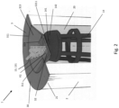
- FIG. 1 and Fig. 2 are partial perspective views of a first embodiment of the present disclosure.
- Figures 3(a) and (b) further illustrate additional features of the first embodiment of the present disclosure.
- a filter cartridge 1 comprises a filtration media arrangement 2 of the pleated filter type, which is arranged in a tubular configuration, and which extends along a longitudinal axis between a first end 21 and a second end 22 and defines an internal volume 20 of the filter cartridge 1.
- the pleated filter pack comprises for instance pleats of constant pleat height, such that both radially inner and outer surfaces of the media arrangement 2 have a cylindrical envelope, the respective cylindrical envelopes being arranged concentrically, i.e. along a common axis.
- the end cap is bound to the first end 21 in a sealing manner.
- the end cap 3 can be bound by plastic injection of the endcap onto the filtration media arrangement or media pack 2, or it can be bonded by direct bonding, or by gluing or using a potting material.
- the first end cap is a closed end cap, in the sense that it does not comprise a feedthrough opening for fluids, preferably air.
- the first end cap 3 comprises a centrally positioned displaceable portion 32 and a deformable portion 31 surrounding the displaceable portion 32.
- the end cap 3 is adapted for allowing a displacement of the displaceable portion 32 along the longitudinal axis between at least a first axial position (P1; Fig. 1 ) and a second axial position (P2; Fig. 2 ) by a deformation of the deformable portion 31.
- the filtration media 2 defines a plane P at or adjacent to the first end 21 of the filtration media 2.
- the displaceable portion 32 is distant from plane P on the side opposite to the side comprising the filtration media 2, when the displaceable portion 32 is in the first axial position P1.
- the displaceable portion 32 is distant from plane P on the side of the filtration media 2, when the displaceable portion 32 is in the second axial position P2.
- the centrally positioned displaceable portion 32 is disc shaped and comprises a circular circumference.
- the deformable portion 31 is an annular portion 313 comprising a circular, radially inner side and a circular radially outer side. On the radially inner side it forms a connection/is connected with the circumference of the displaceable portion 32.
- a fixed annular portion 30 (the portion of the end cap 3 that is attached to the first axial end of the filtration media arrangement or media 2) of the end cap 3, adjacent or directly adjacent to the inner filtration media, i.e., proximate in axial projection (for instance within a radial distance of 5mm, or 3 mm or 1 mm) to the axial projection of the inner surface of the filtration media arrangement.
- the end cap can have a constant thickness, but generally, different portions can have different thicknesses.
- the displaceable portion can have a first thickness
- the deformable portion can have a second, different thickness.
- the second thickness can for instance be smaller than the first thickness.
- the deformable portion 31 further comprises one or more folding lines 311 or portions with reduced thickness 311 to allow folding of the deformable portion 31 in a predetermined manner. These folding lines 311 or portions with reduced thickness 311 can also be referred to as hinge portions 311 and are arranged concentrically in the first end cap 3, preferably in a symmetric manner around the longitudinal axis of the filter element 1.
- the deformable portion comprises two concentric hinge portions 311 connected by a single rigid, but alternatively also flexible, ring portion 313.
- the deformable portion is adapted for deforming only at a predetermined axial threshold force or pressure which is higher than a force or pressure exerted by a differential pressure induced by a predetermined dust loading of the filtration media of the filtration media arrangement 2.
- the displaceable portion 32 should preferably not be able to move between the first and second positions (P1, P2) during use, due to pressures building up over the filter element 1.
- the displaceable portion 32 comprises an inner surface 321 and an outer surface 322 and a first member 3211 of a projection-receiver arrangement arranged on the inner surface 322, which is embodied here as a fin or rib 3211 having elongate shape.
- the first member 3211 of a projection-receiver arrangement is received by a corresponding second member 141 of the projection-receiver arrangement, arranged on a central support structure 14 for supporting the filter cartridge arranged in the main filter housing 10 (see Fig. 3(a) (b) ).
- the support structure is a tower construction having a first end which is arranged around an inlet or outlet of the filter housing 10.
- the tower construction 14 comprises a distal end, remote and at a position opposed to the first end, which comprises an end surface 142.
- the end surface comprises a slot 141 for receiving the fin or rib 3211 and locking the rotational degree of freedom of a filter element around its longitudinal axis.
- the filter cartridge 1 further comprises a second end cap 5 arranged on or at the second end of the filtration media, the second end cap being open and possibly further defining the internal volume of the filter cartridge 1.
- the second end cap 5 is bound to the second end 22 in a sealing manner. For instance, also this end cap can be bound by plastic injection of the endcap onto the media pack 2, or it can be bonded by direct bonding, or by gluing or using a potting material.
- the second end cap 5 is an open end cap in the sense that it comprises a feedthrough opening for fluids, preferably air.
- the second end cap 5 comprises a circumferential seal 6 around the feedthrough opening, which in the example is arranged and adapted for axial sealing, i.e., for sealing towards a filter housing 10 in the axial direction. Alternatively, the seal 6 can be arranged and adapted for radially inward of outward sealing towards the filter housing 10.
- the displaceable portion 32 further comprises a gripping portion 323 on its outer surface 322, allowing the exertion of an axial pulling force by at least one human adult finger, aiding the manipulating from second to first position of the displaceable portion 32.
- a filter assembly comprising the disclosed filter cartridge 1, can receive the filter cartridge 1 in the housing 10 when the displaceable portion 32 is in a first ("elongate") state.
- the element thereby forms a seal with the housing 10 ( Fig. 3(a) ).
- the displaceable portion 32 can be brought into a second ("shortened") state by pushing the displaceable portion towards the tower construction 14 and thereby deforming the deformable portion 31 in a predetermined manner.
- the tower construction 14 comprises a slot 141 at its distal end surface 142, which receives the rib or fin 3211 of the displaceable portion 32, a step that locks the rotation of the filter element 1 along its longitudinal axis ( Fig.
- the housing 10 further comprises a housing cover 13.
- the cover comprises a protrusion 131 on its lower surface (directed towards the housing internal volume) which is arranged and adapted to lock the axial movement of the displaceable portion 32 of the filter cartridge 1, by contacting the displaceable portion or by being directly adjacent to it.
- the tower construction 14 After installation, the tower construction 14 reaches into the inner volume 20 of the filter element 1 and extends up until a level which is below the plane P at the first end 21 of the filtration media 2.
- Figure 3 (c) illustrates further details of a generic filter housing 10 and air cleaner assembly 100, which has not been depicted in relation with the other embodiments for simplicity.
- a main filter housing 100 comprised a filter replacement opening 15 and an internal volume 16 for receiving the filter cartridge 1, which is arranged operatively in the main filter housing 10.
- Cover 13 closes off the main filter housing 10.
- the housing further comprises a fluid inlet (such as a gas, e.g. air) 11 for receiving fluid to be filtered and a fluid outlet 12 for guiding the filtered fluid out of the housing 10 after it is filtered by the media of the filter cartridge 1.
- a support structure/tower construction is arranged with a second end near the outlet 12 of the housing 10, preferably surrounding the outlet 12.
- Fig. 4 (a) and (b) illustrate a second preferred embodiment of the present disclosure.
- This embodiment is similar to the first preferred embodiment but differs in the nature of displacement of the displaceable portion 32 between the first and second positions (P1 ( Fig. 4 (a) ), P2 ( Fig. 4(b) )).
- This cartridge 1 can be used in an associated filter assembly wherein the support structure/tower 114 extends up until a level which is above the plane P at the first end 21 of the filtration media 2.
- the displaceable portion 32 is distant from plane P on the side opposite to the side comprising the filtration media 2, when the displaceable portion 32 is in the first axial position P1.
- the displaceable portion 32 is distant from the plane P on the side opposite to the side comprising the filtration media 2, when said displaceable portion 32 is in said second axial position P2.
- the second axial position P2 is closer to the plane P than the first axial position P1.
- Fig. 5(a) and (b) illustrate a third preferred embodiment of the present disclosure.
- This embodiment is again similar to the first preferred embodiment but differs in the nature of displacement of the displaceable portion 32 between the first and second positions (P1 ( Fig. 5(a) ), P2 ( Fig. 5(b) )).
- the displaceable portion is distant from the plane P on the side of the filtration media when the displaceable portion is in both the first and second axial position; and the second axial position P2 is more distant from the plane P than the first axial position P1.
- the tower construction 114 reaches into the inner volume 20 of the filter element 1 and extends up until a level which is far below the plane P at the first end 21 of the filtration media 2.
- Fig. 6 illustrates an alternative arrangement applicable to any of the first to third embodiments of the present disclosure.
- the support structure for the filter cartridge 1 is a smaller second filter cartridge 1', the second filter cartridge 1' itself being supported in the main filter housing 10 by a support structure or tower 14.
- the second cartridge 1' can be a safety cartridge. It has for instance comprise a filtration media arrangement 2' arranged in a tubular configuration between a first end 21' and a second end 22'. It comprises a first, preferably closed end cap 3', and a second, preferably open, end cap 5' at the second end 22'.
- the end caps can be attached to the respective ends of the filtration media arrangement 2' in a manner as disclosed for the first cartridge 1.
- the end cap 3' comprises a second member of the projection-receiver arrangement 141' on its outer surface, for instance a recess or groove, adapted for cooperating with the fin or rib or other structure of the first member 3211 of a projection-receiver arrangement arranged on the inner surface 321 of the displaceable portion 32 of the first cartridge 1.
- the second cartridge 1' can comprises a circumferential axial or radial seal 6' on the second end cap 5', which seals against the tower 14 or against another portion of the housing 10.
- the second filter cartridge 1' has a rotational fixation with respect to the housing 10 or tower 14, such that the first cartridge 1' also cannot rotate about its axis within the filter housing 10.
- FIGS 7, 8, 9(a) and (b) , 10(a) and (b), 11, 12, 13 and 14 illustrate examples of configurations of the deformable portion, which can be applied to any of the embodiments of the present disclosure.
- All examples describe a filter cartridge 1 comprising a first end cap 3 arranged at the first end 21 of the filtration media 2, the first end cap 3 comprising a deformable portion 31 and a displaceable portion 32 surrounded by said deformable portion 31, wherein said end cap 3 is adapted for allowing a displacement of said displaceable portion 32 along said longitudinal axis between at least a first axial position and a second axial position by a deformation of said deformable portion 31.
- the displaceable portion 32 comprises an inner surface 321 and an outer 322 surface and a first member 3211 of a projection-receiver arrangement arranged on said inner surface 322, for example a fin or rib structure.
- the first end cap 3 further comprises a fixed annular portion 30 (the portion of the end cap 3 that is attached to the first axial end of the filtration media arrangement or media 2).
- the displaceable portion 32 preferably further comprises a gripping portion 323 on its outer surface 322, which is not depicted for simplicity of the drawings.
- the first end cap (3, 30, 31, 32) is all made of, preferably hard, plastic.
- the deformable portion 31 forms a hinged connection with the displaceable portion 32 on one side and a hinged connection with the portion 30 of the end cap 3 that is attached to the first axial end of the filtration media arrangement or media 2 on the opposed side.
- the first member 3211 is also made of hard plastic.
- Fig. 8 illustrates a similar example, wherein the first end cap (3, 30, 31, 32) is all made of, preferably hard, plastic, but wherein the deformable portion 31 comprises two (more generally; a plurality) of concentric rings which are connected by means of a hinge-like connection.
- the deformable portion 31 also forms hinge-like connections with the portion 30 of the end cap 3 that is attached to the first axial end of the filtration media arrangement or media 2 and with the displaceable portion 32.
- Fig. 9(a) (b) illustrate an example wherein the first end cap (3, 30, 31, 32) is made of a preferably soft, preferably foamed, preferably applied by potting, polyurethane (PU) material.
- PU polyurethane
- This material can stretch when having relatively low thickness, and is less or not stretchable for relatively high thickness.
- the portion 30 of the end cap 3 that is attached to the first axial end of the filtration media arrangement or media 2, and the displaceable portion 32 have relatively high thickness and are not deformed under typical manipulation according to the present disclosure.
- the deformable portion 31 is thinner and stretches under applied downward force/pressure.
- the first member 3211 is also made of a PU material or could be for instance a hard plastic component embedded in the PU material of the displaceable portion 32.
- Fig. 10(a) (b) illustrate a similar example as Fig. 9(a) (b) , wherein all of the displaceable portion 32, inclusive the first member 3211, are made of hard plastic and wherein the displaceable portion 32 is embedded in the PU material constituting the rest of the first end cap 3 (30, 31).
- Fig. 11 illustrates an example which is similar to the example of Fig. 8 , but wherein the first member 3211 comprises or is made of a thermo plastic elastomere (TPE).
- TPE thermo plastic elastomere
- Fig. 13 illustrates a further example, that is based on the configurations of Fig. 8 and Fig. 11 , but wherein the fixed portion 30 comprises of consist of PU as discussed for the example of Fig. 9 .
- the fixed portion 30 embeds an anchoring end portion 3a of the plastic deformable portion 31, for instance by overmolding of the PU over the anchoring end portion 3a of the (e.g. hard) plastic deformable portion 31.
- the anchoring end portion 3a of the deformable portion 31 does not deform, but only the complementary portion of the deformable portion 31 can deform.
- the anchoring end portion 3a of the deformable portion 31 is the part of the fixed annular portion 30 of the first end cap 3.
- Fig. 12 illustrates a still further example.
- the fixed portion 30 of the first end cap and the displaceable portion 32, inclusive the first member 3211 comprise or are made of, preferably hard, plastic.
- the deformable portion 31 forms a stretchable connection in between the fixed portion 30 and the displaceable portion 32 and comprises or consists of TPE material, preferably stretchable TPE material.
- the displaceable portion is preferably embedded circumferentially by the TPE material of the deformable portion 31.
- Fig. 14 illustrates another example wherein the first end cap 3 (fixed portion 30, deformable portion 31, displaceable portion 32) comprises or consists of TPE.
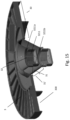
- Fig. 15 illustrates a further advantageous embodiment of the present disclosure.
- the fixed portion 30 is adapted for being fixed to the filtration media 2 and comprises an annular slot 300 for receiving an axial end portion of a tubular filtration media 2. It preferably comprises a hard plastic material, and preferably extends radially, to a limited extent (e.g. 1, 2, 3 cm), into the inner volume 20 of the filter element 1.
- the deformable portion (31, 31') is depicted 'virtually' both in a first axial position and in a second axial position and comprises a flexible and/or stretchable material.
- the deformable portion connects the fixed portion 30 with the displaceable portion 32, which comprises the first member 3211 of the projection-receiver arrangement, protruding into the inner volume 20.
- the displaceable portion 32 consists of the first member 3211, but this is not necessary.
- the first member comprises different cross-sections perpendicular on the longitudinal axis, for different axial positions.
- the cross-section is regular polygon (hexagon).
- the cross-section is circular.
Priority Applications (2)
| Application Number | Priority Date | Filing Date | Title |
|---|---|---|---|
| EP22186803.7A EP4311593A1 (fr) | 2022-07-25 | 2022-07-25 | Éléments et ensembles filtre |
| PCT/US2023/070943 WO2024026310A1 (fr) | 2022-07-25 | 2023-07-25 | Éléments filtrants et ensembles |
Applications Claiming Priority (1)
| Application Number | Priority Date | Filing Date | Title |
|---|---|---|---|
| EP22186803.7A EP4311593A1 (fr) | 2022-07-25 | 2022-07-25 | Éléments et ensembles filtre |
Publications (1)
| Publication Number | Publication Date |
|---|---|
| EP4311593A1 true EP4311593A1 (fr) | 2024-01-31 |
Family
ID=82742612
Family Applications (1)
| Application Number | Title | Priority Date | Filing Date |
|---|---|---|---|
| EP22186803.7A Pending EP4311593A1 (fr) | 2022-07-25 | 2022-07-25 | Éléments et ensembles filtre |
Country Status (2)
| Country | Link |
|---|---|
| EP (1) | EP4311593A1 (fr) |
| WO (1) | WO2024026310A1 (fr) |
Citations (3)
| Publication number | Priority date | Publication date | Assignee | Title |
|---|---|---|---|---|
| WO2009014988A1 (fr) | 2007-07-20 | 2009-01-29 | Donaldson Company, Inc. | Agencements de filtre à air, composants, et procédés |
| US20140008289A1 (en) * | 2008-07-04 | 2014-01-09 | Emerson Electric Co. | Vacuum Appliance Filter Assemblies and Associated Vacuum Systems |
| WO2017108835A1 (fr) * | 2015-12-23 | 2017-06-29 | Mahle Metal Leve S/A | Système de filtre à air, élément filtrant de filtre à air de moteur, et structure interne de support pour un élément filtrant de filtre à air de moteur |
-
2022
- 2022-07-25 EP EP22186803.7A patent/EP4311593A1/fr active Pending
-
2023
- 2023-07-25 WO PCT/US2023/070943 patent/WO2024026310A1/fr unknown
Patent Citations (3)
| Publication number | Priority date | Publication date | Assignee | Title |
|---|---|---|---|---|
| WO2009014988A1 (fr) | 2007-07-20 | 2009-01-29 | Donaldson Company, Inc. | Agencements de filtre à air, composants, et procédés |
| US20140008289A1 (en) * | 2008-07-04 | 2014-01-09 | Emerson Electric Co. | Vacuum Appliance Filter Assemblies and Associated Vacuum Systems |
| WO2017108835A1 (fr) * | 2015-12-23 | 2017-06-29 | Mahle Metal Leve S/A | Système de filtre à air, élément filtrant de filtre à air de moteur, et structure interne de support pour un élément filtrant de filtre à air de moteur |
Also Published As
| Publication number | Publication date |
|---|---|
| WO2024026310A1 (fr) | 2024-02-01 |
Similar Documents
| Publication | Publication Date | Title |
|---|---|---|
| US10737208B2 (en) | Air filter with improved performance or positioning | |
| JP5933572B2 (ja) | フィルタ及びエレメント本体 | |
| US11536171B2 (en) | Filter and removable cartridge including a bypass valve | |
| US5755842A (en) | Air cleaner having removable end cap | |
| US7237682B2 (en) | Filter assembly with slip thread | |
| US7857974B2 (en) | Filter cartridge with snap fit connection | |
| CA2745560C (fr) | Element filtrant et filtre a air comprime pour separer des substances etrangeres se trouvant dans un courant d'air comprime | |
| JP2014502326A5 (fr) | ||
| US20110073538A1 (en) | Standpipe with flow restriction valve, and filter cartridge | |
| US20190293033A1 (en) | Filter with perforated end cap and pre-formed gasket capping perforations | |
| US7749383B2 (en) | Filter cartridge with crush ribs | |
| US11305221B2 (en) | Air filter system, air filter element for use in same, and method for servicing same | |
| US20220347608A1 (en) | Fuel filter cartridge with keyed profile | |
| EP4311593A1 (fr) | Éléments et ensembles filtre | |
| AU2018313998B2 (en) | A spin-on fluid treatment device and methods | |
| US11291934B2 (en) | End cap assembly, filter, and method of use | |
| US20070227964A1 (en) | Fluid filter element and bypass insert | |
| EP2906327B1 (fr) | Élément filtrant et cuve de filtre pour filtre à air comprimé | |
| CN110418675A (zh) | 包括用于联接到流体滤芯的连接器的系统、流体滤芯以及用于生产该流体滤芯的方法 | |
| CN110755953B (zh) | 过滤单元 |
Legal Events
| Date | Code | Title | Description |
|---|---|---|---|
| PUAI | Public reference made under article 153(3) epc to a published international application that has entered the european phase |
Free format text: ORIGINAL CODE: 0009012 |
|
| STAA | Information on the status of an ep patent application or granted ep patent |
Free format text: STATUS: THE APPLICATION HAS BEEN PUBLISHED |
|
| AK | Designated contracting states |
Kind code of ref document: A1 Designated state(s): AL AT BE BG CH CY CZ DE DK EE ES FI FR GB GR HR HU IE IS IT LI LT LU LV MC MK MT NL NO PL PT RO RS SE SI SK SM TR |