EP3777704B1 - Dispositifs d'occlusion intravasculaire dirigés par cathéter percutané - Google Patents
Dispositifs d'occlusion intravasculaire dirigés par cathéter percutané Download PDFInfo
- Publication number
- EP3777704B1 EP3777704B1 EP20192239.0A EP20192239A EP3777704B1 EP 3777704 B1 EP3777704 B1 EP 3777704B1 EP 20192239 A EP20192239 A EP 20192239A EP 3777704 B1 EP3777704 B1 EP 3777704B1
- Authority
- EP
- European Patent Office
- Prior art keywords
- diameter
- disk
- occlusion device
- catheter
- delivery
- Prior art date
- Legal status (The legal status is an assumption and is not a legal conclusion. Google has not performed a legal analysis and makes no representation as to the accuracy of the status listed.)
- Active
Links
- 239000004744 fabric Substances 0.000 claims abstract description 46
- 239000002184 metal Substances 0.000 claims abstract description 21
- 229910052751 metal Inorganic materials 0.000 claims abstract description 21
- 230000007704 transition Effects 0.000 claims abstract description 15
- 230000014759 maintenance of location Effects 0.000 claims abstract description 10
- 239000000835 fiber Substances 0.000 claims description 12
- 230000033001 locomotion Effects 0.000 claims description 8
- 229910001000 nickel titanium Inorganic materials 0.000 claims description 8
- HLXZNVUGXRDIFK-UHFFFAOYSA-N nickel titanium Chemical compound [Ti].[Ti].[Ti].[Ti].[Ti].[Ti].[Ti].[Ti].[Ti].[Ti].[Ti].[Ni].[Ni].[Ni].[Ni].[Ni].[Ni].[Ni].[Ni].[Ni].[Ni].[Ni].[Ni].[Ni].[Ni] HLXZNVUGXRDIFK-UHFFFAOYSA-N 0.000 claims description 7
- 238000005452 bending Methods 0.000 claims description 4
- 239000008280 blood Substances 0.000 claims description 4
- 210000004369 blood Anatomy 0.000 claims description 4
- 238000006073 displacement reaction Methods 0.000 claims description 2
- 208000007536 Thrombosis Diseases 0.000 claims 1
- 230000015572 biosynthetic process Effects 0.000 claims 1
- 230000002401 inhibitory effect Effects 0.000 claims 1
- 238000011282 treatment Methods 0.000 abstract description 9
- 206010053648 Vascular occlusion Diseases 0.000 abstract description 2
- 230000002829 reductive effect Effects 0.000 abstract description 2
- 208000021331 vascular occlusion disease Diseases 0.000 abstract description 2
- 230000002159 abnormal effect Effects 0.000 abstract 1
- 210000000056 organ Anatomy 0.000 abstract 1
- 208000013914 atrial heart septal defect Diseases 0.000 description 23
- 238000000034 method Methods 0.000 description 14
- 208000003278 patent ductus arteriosus Diseases 0.000 description 14
- 238000000465 moulding Methods 0.000 description 13
- 208000001910 Ventricular Heart Septal Defects Diseases 0.000 description 8
- 238000013461 design Methods 0.000 description 8
- 238000010438 heat treatment Methods 0.000 description 8
- 230000017531 blood circulation Effects 0.000 description 7
- 229920000728 polyester Polymers 0.000 description 7
- PXHVJJICTQNCMI-UHFFFAOYSA-N Nickel Chemical compound [Ni] PXHVJJICTQNCMI-UHFFFAOYSA-N 0.000 description 6
- 210000003484 anatomy Anatomy 0.000 description 6
- 230000006872 improvement Effects 0.000 description 6
- 230000002792 vascular Effects 0.000 description 6
- 229910045601 alloy Inorganic materials 0.000 description 4
- 239000000956 alloy Substances 0.000 description 4
- 230000003466 anti-cipated effect Effects 0.000 description 4
- 210000004204 blood vessel Anatomy 0.000 description 4
- 230000007547 defect Effects 0.000 description 4
- 239000000463 material Substances 0.000 description 4
- 230000004048 modification Effects 0.000 description 4
- 238000012986 modification Methods 0.000 description 4
- 230000002441 reversible effect Effects 0.000 description 4
- 238000004513 sizing Methods 0.000 description 4
- 210000005166 vasculature Anatomy 0.000 description 4
- 229920002614 Polyether block amide Polymers 0.000 description 3
- 230000009471 action Effects 0.000 description 3
- 238000009954 braiding Methods 0.000 description 3
- 239000003795 chemical substances by application Substances 0.000 description 3
- 229910052759 nickel Inorganic materials 0.000 description 3
- RVTZCBVAJQQJTK-UHFFFAOYSA-N oxygen(2-);zirconium(4+) Chemical compound [O-2].[O-2].[Zr+4] RVTZCBVAJQQJTK-UHFFFAOYSA-N 0.000 description 3
- 230000008569 process Effects 0.000 description 3
- 230000002885 thrombogenetic effect Effects 0.000 description 3
- 238000011265 2D-echocardiography Methods 0.000 description 2
- 208000035478 Interatrial communication Diseases 0.000 description 2
- 206010003664 atrial septal defect Diseases 0.000 description 2
- 210000003157 atrial septum Anatomy 0.000 description 2
- 239000000969 carrier Substances 0.000 description 2
- 238000005520 cutting process Methods 0.000 description 2
- 238000007373 indentation Methods 0.000 description 2
- 238000004519 manufacturing process Methods 0.000 description 2
- 238000013507 mapping Methods 0.000 description 2
- 230000004962 physiological condition Effects 0.000 description 2
- 230000002685 pulmonary effect Effects 0.000 description 2
- 230000000717 retained effect Effects 0.000 description 2
- 238000007789 sealing Methods 0.000 description 2
- 229910001285 shape-memory alloy Inorganic materials 0.000 description 2
- 239000007787 solid Substances 0.000 description 2
- 239000010935 stainless steel Substances 0.000 description 2
- 229910001220 stainless steel Inorganic materials 0.000 description 2
- 206010053567 Coagulopathies Diseases 0.000 description 1
- 206010014666 Endocarditis bacterial Diseases 0.000 description 1
- 206010016717 Fistula Diseases 0.000 description 1
- 206010020772 Hypertension Diseases 0.000 description 1
- 239000004677 Nylon Substances 0.000 description 1
- 230000006978 adaptation Effects 0.000 description 1
- 238000004873 anchoring Methods 0.000 description 1
- 210000000709 aorta Anatomy 0.000 description 1
- 238000013459 approach Methods 0.000 description 1
- 230000001746 atrial effect Effects 0.000 description 1
- 208000009361 bacterial endocarditis Diseases 0.000 description 1
- 230000005540 biological transmission Effects 0.000 description 1
- 229920001400 block copolymer Polymers 0.000 description 1
- 230000035602 clotting Effects 0.000 description 1
- 229910017052 cobalt Inorganic materials 0.000 description 1
- 239000010941 cobalt Substances 0.000 description 1
- GUTLYIVDDKVIGB-UHFFFAOYSA-N cobalt atom Chemical compound [Co] GUTLYIVDDKVIGB-UHFFFAOYSA-N 0.000 description 1
- 238000010276 construction Methods 0.000 description 1
- 230000003247 decreasing effect Effects 0.000 description 1
- 230000001419 dependent effect Effects 0.000 description 1
- 238000003745 diagnosis Methods 0.000 description 1
- 201000010099 disease Diseases 0.000 description 1
- 208000037265 diseases, disorders, signs and symptoms Diseases 0.000 description 1
- 230000010102 embolization Effects 0.000 description 1
- 210000001174 endocardium Anatomy 0.000 description 1
- 230000003511 endothelial effect Effects 0.000 description 1
- 238000001125 extrusion Methods 0.000 description 1
- 210000003191 femoral vein Anatomy 0.000 description 1
- 238000001914 filtration Methods 0.000 description 1
- 230000003890 fistula Effects 0.000 description 1
- 239000012530 fluid Substances 0.000 description 1
- 230000006870 function Effects 0.000 description 1
- 229910000856 hastalloy Inorganic materials 0.000 description 1
- 208000025339 heart septal defect Diseases 0.000 description 1
- 229910001293 incoloy Inorganic materials 0.000 description 1
- 201000007119 infective endocarditis Diseases 0.000 description 1
- 238000003780 insertion Methods 0.000 description 1
- 230000037431 insertion Effects 0.000 description 1
- 210000005246 left atrium Anatomy 0.000 description 1
- 230000013011 mating Effects 0.000 description 1
- 229920001778 nylon Polymers 0.000 description 1
- 239000011368 organic material Substances 0.000 description 1
- 230000036961 partial effect Effects 0.000 description 1
- 239000004810 polytetrafluoroethylene Substances 0.000 description 1
- 229920001343 polytetrafluoroethylene Polymers 0.000 description 1
- 230000000750 progressive effect Effects 0.000 description 1
- 210000001147 pulmonary artery Anatomy 0.000 description 1
- 238000012797 qualification Methods 0.000 description 1
- 230000004044 response Effects 0.000 description 1
- 238000000926 separation method Methods 0.000 description 1
- 229910000679 solder Inorganic materials 0.000 description 1
- 229910000601 superalloy Inorganic materials 0.000 description 1
- 201000009371 venous hemangioma Diseases 0.000 description 1
- 201000003130 ventricular septal defect Diseases 0.000 description 1
- 239000002759 woven fabric Substances 0.000 description 1
Images


Classifications
-
- A—HUMAN NECESSITIES
- A61—MEDICAL OR VETERINARY SCIENCE; HYGIENE
- A61B—DIAGNOSIS; SURGERY; IDENTIFICATION
- A61B17/00—Surgical instruments, devices or methods, e.g. tourniquets
-
- A—HUMAN NECESSITIES
- A61—MEDICAL OR VETERINARY SCIENCE; HYGIENE
- A61B—DIAGNOSIS; SURGERY; IDENTIFICATION
- A61B17/00—Surgical instruments, devices or methods, e.g. tourniquets
- A61B17/0057—Implements for plugging an opening in the wall of a hollow or tubular organ, e.g. for sealing a vessel puncture or closing a cardiac septal defect
-
- A—HUMAN NECESSITIES
- A61—MEDICAL OR VETERINARY SCIENCE; HYGIENE
- A61B—DIAGNOSIS; SURGERY; IDENTIFICATION
- A61B17/00—Surgical instruments, devices or methods, e.g. tourniquets
- A61B17/08—Wound clamps or clips, i.e. not or only partly penetrating the tissue ; Devices for bringing together the edges of a wound
-
- A—HUMAN NECESSITIES
- A61—MEDICAL OR VETERINARY SCIENCE; HYGIENE
- A61B—DIAGNOSIS; SURGERY; IDENTIFICATION
- A61B17/00—Surgical instruments, devices or methods, e.g. tourniquets
- A61B17/12—Surgical instruments, devices or methods, e.g. tourniquets for ligaturing or otherwise compressing tubular parts of the body, e.g. blood vessels, umbilical cord
- A61B17/12022—Occluding by internal devices, e.g. balloons or releasable wires
- A61B17/12099—Occluding by internal devices, e.g. balloons or releasable wires characterised by the location of the occluder
- A61B17/12109—Occluding by internal devices, e.g. balloons or releasable wires characterised by the location of the occluder in a blood vessel
-
- A—HUMAN NECESSITIES
- A61—MEDICAL OR VETERINARY SCIENCE; HYGIENE
- A61B—DIAGNOSIS; SURGERY; IDENTIFICATION
- A61B17/00—Surgical instruments, devices or methods, e.g. tourniquets
- A61B17/12—Surgical instruments, devices or methods, e.g. tourniquets for ligaturing or otherwise compressing tubular parts of the body, e.g. blood vessels, umbilical cord
- A61B17/12022—Occluding by internal devices, e.g. balloons or releasable wires
- A61B17/12099—Occluding by internal devices, e.g. balloons or releasable wires characterised by the location of the occluder
- A61B17/12122—Occluding by internal devices, e.g. balloons or releasable wires characterised by the location of the occluder within the heart
-
- A—HUMAN NECESSITIES
- A61—MEDICAL OR VETERINARY SCIENCE; HYGIENE
- A61B—DIAGNOSIS; SURGERY; IDENTIFICATION
- A61B17/00—Surgical instruments, devices or methods, e.g. tourniquets
- A61B17/12—Surgical instruments, devices or methods, e.g. tourniquets for ligaturing or otherwise compressing tubular parts of the body, e.g. blood vessels, umbilical cord
- A61B17/12022—Occluding by internal devices, e.g. balloons or releasable wires
- A61B17/12131—Occluding by internal devices, e.g. balloons or releasable wires characterised by the type of occluding device
- A61B17/12168—Occluding by internal devices, e.g. balloons or releasable wires characterised by the type of occluding device having a mesh structure
- A61B17/12172—Occluding by internal devices, e.g. balloons or releasable wires characterised by the type of occluding device having a mesh structure having a pre-set deployed three-dimensional shape
-
- A—HUMAN NECESSITIES
- A61—MEDICAL OR VETERINARY SCIENCE; HYGIENE
- A61B—DIAGNOSIS; SURGERY; IDENTIFICATION
- A61B17/00—Surgical instruments, devices or methods, e.g. tourniquets
- A61B17/12—Surgical instruments, devices or methods, e.g. tourniquets for ligaturing or otherwise compressing tubular parts of the body, e.g. blood vessels, umbilical cord
- A61B17/12022—Occluding by internal devices, e.g. balloons or releasable wires
- A61B17/12131—Occluding by internal devices, e.g. balloons or releasable wires characterised by the type of occluding device
- A61B17/12168—Occluding by internal devices, e.g. balloons or releasable wires characterised by the type of occluding device having a mesh structure
- A61B17/12177—Occluding by internal devices, e.g. balloons or releasable wires characterised by the type of occluding device having a mesh structure comprising additional materials, e.g. thrombogenic, having filaments, having fibers or being coated
-
- A—HUMAN NECESSITIES
- A61—MEDICAL OR VETERINARY SCIENCE; HYGIENE
- A61F—FILTERS IMPLANTABLE INTO BLOOD VESSELS; PROSTHESES; DEVICES PROVIDING PATENCY TO, OR PREVENTING COLLAPSING OF, TUBULAR STRUCTURES OF THE BODY, e.g. STENTS; ORTHOPAEDIC, NURSING OR CONTRACEPTIVE DEVICES; FOMENTATION; TREATMENT OR PROTECTION OF EYES OR EARS; BANDAGES, DRESSINGS OR ABSORBENT PADS; FIRST-AID KITS
- A61F2/00—Filters implantable into blood vessels; Prostheses, i.e. artificial substitutes or replacements for parts of the body; Appliances for connecting them with the body; Devices providing patency to, or preventing collapsing of, tubular structures of the body, e.g. stents
-
- A—HUMAN NECESSITIES
- A61—MEDICAL OR VETERINARY SCIENCE; HYGIENE
- A61M—DEVICES FOR INTRODUCING MEDIA INTO, OR ONTO, THE BODY; DEVICES FOR TRANSDUCING BODY MEDIA OR FOR TAKING MEDIA FROM THE BODY; DEVICES FOR PRODUCING OR ENDING SLEEP OR STUPOR
- A61M25/00—Catheters; Hollow probes
- A61M25/01—Introducing, guiding, advancing, emplacing or holding catheters
-
- A—HUMAN NECESSITIES
- A61—MEDICAL OR VETERINARY SCIENCE; HYGIENE
- A61B—DIAGNOSIS; SURGERY; IDENTIFICATION
- A61B17/00—Surgical instruments, devices or methods, e.g. tourniquets
- A61B17/0057—Implements for plugging an opening in the wall of a hollow or tubular organ, e.g. for sealing a vessel puncture or closing a cardiac septal defect
- A61B2017/00575—Implements for plugging an opening in the wall of a hollow or tubular organ, e.g. for sealing a vessel puncture or closing a cardiac septal defect for closure at remote site, e.g. closing atrial septum defects
- A61B2017/00592—Elastic or resilient implements
-
- A—HUMAN NECESSITIES
- A61—MEDICAL OR VETERINARY SCIENCE; HYGIENE
- A61B—DIAGNOSIS; SURGERY; IDENTIFICATION
- A61B17/00—Surgical instruments, devices or methods, e.g. tourniquets
- A61B17/0057—Implements for plugging an opening in the wall of a hollow or tubular organ, e.g. for sealing a vessel puncture or closing a cardiac septal defect
- A61B2017/00575—Implements for plugging an opening in the wall of a hollow or tubular organ, e.g. for sealing a vessel puncture or closing a cardiac septal defect for closure at remote site, e.g. closing atrial septum defects
- A61B2017/00606—Implements H-shaped in cross-section, i.e. with occluders on both sides of the opening
-
- A—HUMAN NECESSITIES
- A61—MEDICAL OR VETERINARY SCIENCE; HYGIENE
- A61B—DIAGNOSIS; SURGERY; IDENTIFICATION
- A61B17/00—Surgical instruments, devices or methods, e.g. tourniquets
- A61B17/0057—Implements for plugging an opening in the wall of a hollow or tubular organ, e.g. for sealing a vessel puncture or closing a cardiac septal defect
- A61B2017/00575—Implements for plugging an opening in the wall of a hollow or tubular organ, e.g. for sealing a vessel puncture or closing a cardiac septal defect for closure at remote site, e.g. closing atrial septum defects
- A61B2017/00628—T-shaped occluders
-
- A—HUMAN NECESSITIES
- A61—MEDICAL OR VETERINARY SCIENCE; HYGIENE
- A61B—DIAGNOSIS; SURGERY; IDENTIFICATION
- A61B17/00—Surgical instruments, devices or methods, e.g. tourniquets
- A61B17/0057—Implements for plugging an opening in the wall of a hollow or tubular organ, e.g. for sealing a vessel puncture or closing a cardiac septal defect
- A61B2017/00575—Implements for plugging an opening in the wall of a hollow or tubular organ, e.g. for sealing a vessel puncture or closing a cardiac septal defect for closure at remote site, e.g. closing atrial septum defects
- A61B2017/00632—Occluding a cavity, i.e. closing a blind opening
-
- A—HUMAN NECESSITIES
- A61—MEDICAL OR VETERINARY SCIENCE; HYGIENE
- A61B—DIAGNOSIS; SURGERY; IDENTIFICATION
- A61B17/00—Surgical instruments, devices or methods, e.g. tourniquets
- A61B2017/00831—Material properties
- A61B2017/00867—Material properties shape memory effect
Definitions
- the present invention generally relates to intravascular devices for treating certain medical conditions and, more particularly, relates to intravascular occlusion devices for selective occlusion of a vessel anywhere in the body's circulatory system where it is desired to stop the flow of blood.
- the devices made in accordance with the invention are particularly well suited for delivery through a catheter or the like to a remote location in a patient's vascular system within a patient's body whereby a passageway to be occluded, has an axis and at least one aperture which intersects another vessel wall somewhat perpendicular to the axis.
- intravascular devices are used in various medical procedures. Certain intravascular devices, such as catheters and guidewires, are generally used simply to deliver fluids or other medical devices to specific locations within a patient's body, such as a selective site within the vascular system. Other, frequently more complex, devices are used in treating specific conditions, such as devices used in removing vascular occlusions or for treating septal defects and the like.
- Patents 6,123,715 by Amplatz and patent 5,725,552 by Kotula disclose intravascular occlusion devices fabricated from Nitinol braided metal fabric which are heat-set in molds to an expanded shape, but which can be compressed for delivery through a catheter to a treatment site, whereby the device, when urged out of the delivery catheter, self expands within the vasculature to occlude blood flow at the treatment site.
- the details of the various designs and configurations, as well as methods of fabricating and using the devices, are detailed in the aforementioned patents.
- VSD Ventricular Septal Defects
- ASD Atrial Septal Defects
- PFO Patent Foraman Ovale
- WO 02/071977 A2 discloses a device for filtering blood flow through a body aperture comprising a proximal cover substructure formed to a cylinder-shaped wire braid device structure.
- the prior art devices represented by the Amplatz and Kotula patents are retained in place, as deployed, by sizing the cylindrical portion diameter larger in its unrestrained self expanding condition larger than the diameter of the vessel to be occluded. This imparts a load from the Nitinol braid's desire to expand larger to be imparted against the body lumen tissue to secure the device in place. Due to lack of precision in estimating the diameter of the vessel to be occluded or the body's ability to yield or dilate in response to pressure changes, and movement of the body, the retention force can occasionally be insufficient to retain the device in place as desired.
- the occlusion device is defined in claim 1. Particular embodiments are defined in the dependent claims.
- the present invention is well suited for the selective occlusion of a vessel, lumen, channel, or cavity having an axis and at least one aperture which intersects another vessel wall somewhat perpendicular (+ or - 45 degrees) to the axis.
- PDA Patent Ductus Arteriosus
- ASD Atrial Septal Defect
- VSD Ventricular Septal Defect
- ASD Atrial Septal Defect
- VSD Ventricular Septal Defect
- Another example could be an arterial venous fistula (AVF) or arterial venous malformation (AVM).
- a plurality of resilient strands is provided, with the wires being formed by braiding to create a resilient metallic fabric which can be heat treated to substantially set a desired shape.
- This braided fabric is then deformed to generally conform to a molding surface of a molding element and the braided fabric is heat treated in contact with the surface of the molding element at an elevated temperature.
- the time and temperature of the heat treatment is selected to substantially set the braided fabric in its deformed state.
- the fabric is removed from contact with the molding element and will substantially retain its shape in the deformed state.
- the braided fabric, so treated defines an expanded state of a medical device which can be deployed through a catheter into a channel in a patient's body.
- Embodiments of the present invention provide specific shape improvements over prior art medical devices to address occlusion of vessels having specific anatomical conditions.
- Such devices of the present invention are formed of a braided metal fabric and have an expanded configuration and a collapsed configuration.
- a guide catheter can be positioned in a channel in a patient's body and advanced to position the distal end of the catheter adjacent a treatment site for treating a physiological condition.
- a medical device formed in a predetermined shape, and made in accordance with the process outlined above, can be collapsed and inserted into the lumen of the catheter. The device is urged through the catheter and out the distal end, whereupon, due to its memory property, it will tend to substantially return to its expanded state adjacent the treatment site.
- a generally elongate medical device has a generally cylindrical middle portion and a pair of expanded diameter disk portions, with one expanded diameter portion positioned at either end of the middle portion.
- the medical device is generally bell-shaped, having an elongate cylindrical portion having a tapered first end and a larger diameter second disked end, the second end presenting a fabric disc which will be oriented generally perpendicular to an axis of a vessel, channel, lumen, or cavity when deployed therein.
- the inventive device improves the flexibility between the disk portion and the cylindrical middle portion by providing a very small transition diameter between the disk portion and middle portion, the transition diameter being much smaller than the middle portion diameter.
- This small transition diameter allows the disk to easily flex about this diameter to orient itself to the wall of the vessel containing the aperture to accommodate a wide range of anatomical variations between the axis of the lumen to be occluded and the wall containing the aperture to the lumen.
- the improved single disk device also has improved retention when compared to the prior art by the addition of flexible Nitinol shape memory wires sutured or fastened to or a part of the braided structure middle portion.
- the wires have a resilient hook end, designed to extend outward from the device middle portion surface, upon deployment, to reversibly engage the vessel wall to resist motion of the device toward the disk end.
- the hook end has no barb and allows the device to be repositioned by device movement opposite in direction (away from disk) to the pointed end of the hook.
- the device may also be withdrawn back into the delivery catheter after deployment by resiliently un-bending the hook as it is drawn back into the distal end of the catheter.
- the hook shaped wires add additional device retention to that provided by the sizing of the middle portion diameter larger than the vessel to be occluded.
- the present invention provides an improved percutaneous catheter directed intravascular occlusion device for use in the vasculature in patients' bodies, such as blood vessels, channels, lumens, a hole through tissue, cavities and the like.
- a metal fabric is formed of a plurality of wire strands having a predetermined relative orientation between the strands.
- the metal strands define two sets of essentially parallel generally helical strands, with the strands of one set having a "hand", i.e. a direction of rotation, opposite that of the other set.
- This defines a generally tubular fabric, known in the fabric industry as a tubular braid.
- the Amplatz and Kotula patents previously discussed describe medical devices and the methods of fabrication of such devices in great detail and detailed further discussion is not needed.
- the pitch of the wire strands i.e. the angle defined between the turns of the wire and the axis of the braid
- the pick of the fabric i.e. the number of wire crossovers per unit length
- the wire strands of the metal fabric used in the present method should be formed of a material which is both resilient and which can be heat treated to substantially set a desired shape.
- Materials which are suitable for this purpose include a cobalt-based low thermal expansion alloy referred to in the field as Elgeloy, nickel-based high temperature high-strength "superalloys" commercially available from Haynes International under the trade name Hastelloy, nickel-based heat treatable alloys sold under the name Incoloy by International Nickel, and a number of different grades of stainless steel.
- a cobalt-based low thermal expansion alloy referred to in the field as Elgeloy
- nickel-based high temperature high-strength "superalloys” commercially available from Haynes International under the trade name Hastelloy
- nickel-based heat treatable alloys sold under the name Incoloy by International Nickel and a number of different grades of stainless steel.
- the important factor in choosing a suitable material for the wires is that the wires retain a suitable amount of the deformation induced by the molding surface (as described below) when subjected to a predetermined heat treatment.
- shape memory alloys One class of materials which meet these qualifications is so-called shape memory alloys.
- One particularly preferred shape memory alloy for use in the present method is Nitinol.NiTi alloys are also very elastic--they are said to be “superelastic” or “pseudoelastic”. This elasticity will help a device of the invention return to a present expanded configuration for deployment following passage in a distorted form through a delivery catheter.
- an appropriately sized piece of the metal fabric is cut from the larger piece of fabric which is formed, for example, by braiding wire strands to form a long tubular braid.
- the fabric is deformed to generally conform to a surface of a molding element. Deforming the fabric will reorient the relative positions of the strands of the metal fabric from their initial order to a second, reoriented configuration.
- the shape of the molding element should be selected to deform the fabric into substantially the shape of the desired medical device when unconstrained.
- the fabric can be subjected to a heat treatment while it remains in contact with that molding surface.
- Suitable heat treatments of Nitinol wire to set a desired shape are well known in the art. It has been found that holding a Nitinol fabric at about 500 deg. C to about 550 deg. C for a period of about 1 to about 30 minutes, depending on the softness or harness of the device to be made, will tend to set the fabric in its deformed state, i.e. wherein it conforms to the molding surface of the molding element. At lower temperatures the heat treatment time will tend to be greater (e.g. about one hour at about 350 deg. C.) and at higher temperatures the time will tend to be shorter (e.g. about 30 seconds at about 900 deg. C).
- the fabric After the heat treatment, the fabric is removed from contact with the molding element and will substantially retain its shape in a deformed state
- FIGS. 5A and 5B illustrate an embodiment of a medical device 10 in accordance with the present invention.
- This device 10 has a generally cylindrical body portion 12 and an outwardly extending forward disk end 14.
- the cylindrical body portion 12 is sized to be somewhat larger (about 10-30%), than the vessel to be occluded. This sizing is intended to provide one element of anchoring the device to prevent dislodgement.
- the disk portion of the device 14 is intended to abut the adjacent wall surrounding the aperture, to prevent device movement toward the cylindrical portion direction and to assist is sealing the aperture.
- the improvement over the prior art incorporates a transition diameter H, between the cylindrical portion 12, and the disk portion 14 that is small in relationship to the cylindrical diameter B, and the disk diameter A.
- This small transition diameter allow the disk portion to easily orient itself to the vessel wall containing the aperture where the wall is not truly perpendicular (perpendicular + or - 45 degrees).
- the recessed transition diameter H within an indentation 15 in the end of the cylindrical body will allow the device to conform to the anatomy in which the device is being positioned by acting like a spring member for maintaining tension between the disk and the cylindrical body. Separation between the disk and the cylindrical body will not impact device performance.
- PDA patent ductus arteriosus
- aorta and pulmonary artery adjacent the heart have a blood flow shunt between their lumens. Blood can flow directly between these two blood vessels through the passageway, compromising the normal flow of blood through the patient's vessels.
- Other physiologic conditions in the body occur where it is also desirous to occlude a vessel to prevent blood flow through the vessel.
- This device embodiment may be used anywhere in the vasculature where the anatomical conditions are appropriate for the design.
- the cylindrical shaped body 12 is adapted to be deployed within the vessel to be occluded, while the disk 14 is adapted to be positioned adjacent the wall surrounding the aperture associated with the vessel to be occluded.
- the braided metal fabric extends from the proximal disk end clamp 16, radially outward to the disk maximum diameter A and back radially inward against itself to the transitional diameter H.
- the transitional diameter extends distally a distance J whereby the fabric forms a reverse cone toward the disk with a diameter K where the fabric turns to follow parallel to the disk but spaced from the disk a distance E, radially outward to a diameter B.
- the fabric continues to maintain cylindrical diameter B distally a distance D, then forming a taper surface of angle C to a total cylindrical portion length G.
- the distal end clamp 18 and the proximal end clamp 16 hold the braided wire ends from unraveling.
- the proximal end clamp 16 also contains a threaded portion that reversibly connects to a delivery system (not shown) such as a cable or shaft with mating threads at its end.
- the improvement in disk flexibility and conformance to a vessel wall which are not perpendicular to the axis of the vessel to be occluded comes from the disk maximum diameter A in relation to the small diameter H, or the ratio of A/H.
- this ratio is about 1.9, but in the improved design of FIGs. 5A and 5B the ratio is in the range of 3 to 30, preferably about 10 to 20-25.
- the ratio for the cylindrical body 12 diameter B to the disk transition diameter H is 1.0 since there is no reduced transition diameter.
- the ratio B/H is in the range of 2-25 and preferably 10-20.
- the transition diameter H has a length J which is about 2-5 times the diameter H. This length J is necessary to allow a small dimension E between the disk inner surface and the cylindrical portion proximal end wall as shown in FIG. 5A . This improves the device fit and improves the sealing of the device.
- the fabric is shaped to form a conical surface at an angle L to the proximal end wall of the cylindrical portion. This conical surface accommodates user displacement of the cylindrical portion from adjacent the disk by cone flattening and thereby provides increased radial expansive force for device retention on the proximal cylindrical outer diameter. Additionally, the conical surface acts as a spring to provide axial tension between the disk and cylindrical portion when they are displaced apart to keep the hooks 20 engaged in the wall of the vessel being occluded, thus improving device retention.
- retention hooks 20 are preferably fabricated from Nitinol wire heat set into a hook shape at each end and a bend of about 180 degrees in the mid length segment of the wire to create 2 interconnected hooks.
- the hooks could be a part of the device - i.e. individual wires within the braided structure that are isolated and formed into hooks. The ends of the hooks are oriented toward the disk and sutured 22 or fastened by any known means to the braided fabric on the cylindrical portion 12 of the device.
- the hook wires 20 are preferably about .007 inches (one inch corresponds to 2,54 cm) in diameter and 3 mm in length and flexible enough to be back loaded into the delivery catheter or forward loaded, if introduced in a straightened out configuration.
- the device may have any number of these hooks, but preferably has three pairs of hooks. The number of hooks would preferable range from 6 to 12.
- the hooks assist in the retention of the device by resisting motion of the device in the vessel in a direction that would cause the hooks to engage the tissue.
- the hooks 20 do not have barbs so that the engagement is reversible by movement of the device opposite to the open end of the hook.
- the art pertaining to vascular grafts has many examples of alternative hooks that maybe incorporated into vascular implantable devices.
- the device may be coated with a suitable thrombogenic agent, filled with a polyester fiber or braided with an increased number of wire strands.
- the prior art devices have preferably used a polyester fiber (303 as shown in FIG 6 ) within the braided device. This fiber easily collapses with the device for delivery through a catheter. The interwoven fiber by attachment to clot retains the clot firmly within the device as it forms the occlusion.
- the delivery device 28 shown in FIG. 6 can be used to urge the PDA occlusion device 10 through the lumen of a catheter or long introducer sheath for deployment in a channel of the patient's body. When the device is deployed out the distal end of the catheter, the device will still be retained by the delivery device. Once the proper position of the device 10 in the vessel is confirmed, the shaft of the delivery device 28 can be rotated about its axis to unscrew the clamp 16 from the threaded end of delivery means.
- the threaded connection could be at either end of the device depending on the anatomical situation and the desired or available means of access to the treatment site.
- the tubular braid used to fabricate occlusion devices of this invention may range from wire having a diameter of 0.002 to 0.005 in., preferably in the range of 0.003 to 0.0035 in., and for a PDA device, preferably 0.003 in. diameter.
- the number of wires in the tubular braid may vary from 36 to 144 but preferably is in the range of 72 to 144 and for a PDA device is preferably 144 wires.
- the pick count of the braid may vary from 30 to 100 and preferably from 50 to 80 and for a PDA device is preferably 70.
- the sizes of the body 12 and the disk 14 and device length can be varied as desired for differently sized vessels, channels, lumens or cavities.
- a table of dimensional ranges and for select devices is provided below in mm. TABLE I A B C D E F G H J K L Range 6 to 35 2 to 28 20 to 70 2 to 20 0 to 6 1 to 3 3 to 25 1 to 8 0 to 10 3 to 20 20 to 70 PDA 8 4 45 4 1 1 6 1 2 3 20 Another 23 18 45 10 0 2 14 2 4 8 30
- the operator may still retract the device back into a delivery sheath for repositioning if it is determined that the device is not properly positioned in the first attempt.
- This threaded attachment will also allow the operator to control the manner in which the device 10 is deployed out of the distal end of the delivery catheter. As explained below, when the device exits the delivery catheter it will tend to resiliently return to a preferred expanded shape which was set when the fabric was heat treated. When the device springs back into this shape, it may tend to act against the distal end of the catheter, effectively urging itself forward beyond the end of the catheter. This spring action could conceivably result in improper positioning of the device. Since the threaded clamp 16 can enable the operator to maintain a hold on the device during deployment, the spring action of the device can be controlled and the operator can control the deployment to ensure proper positioning.
- the device as shown in FIG. 6 could be configured with a hollow inner clamp member 23 at both wire ends and a outer clamp proximal member 21 and a distal outer clamp member 26.
- the wire ends 24 are crimped between the inner and outer clamp members 21, 26 by swaging or alternatively may be bonded or welded between the clamp members.
- the inner clamp member is tubular and is sized with an inside diameter to freely pass a push wire 27.
- the distal outer clamp member 26 is sized with an inside diameter sufficient to accommodate the braid wire ends 24 surrounding the inner clamp member prior to swaging.
- the distal end on the distal outer clamp member 26 is solid (closed end) to accept the push force from the push wire 27 placed through both inner clamp members against this solid end.
- the proximal outer clamp member 21 is shown with external threads to reversibly connect to the delivery system 28, which is preferably a nylon block co-polymer such as Pebax with a .001 in. braided wire over the Pebax inner tube extrusion, followed by another outer layer of Pebax to cover the braid.
- the delivery catheter/sheath 29 may be similarly constructed except larger in diameter to accommodate the passage of the device 10 and delivery system 28. Such construction is typical in intravascular catheters where a flexibility and torque transmission are needed.
- the delivery catheter sheath 29 may have a .001 in thick layer of PTFE to lower friction for ease of device passage therethrough.
- the hollow delivery system sized to allow a push wire 27, made of stainless steel .008-.014 in. to pass through the delivery system and the proximal clamp and to engage the distal clamp to push the distal clamp away from the proximal clamp to elongate the device, facilitate release of the hooks and facilitate recapture of the device into the delivery sheath 29.
- the distal end of the push wire 27 and the distal inner clamp 23 may be designed to attach by a threaded connection or other reversible means to ensure the wire does not inadvertently get positioned proximal to the distal inner clamp 23.
- a spring positioned between the delivery system 28 and the push wire 27 could maintain the push wire against the distal outer clamp 26.
- the delivery system 28 maintaining control of the proximal end of the device 10 and the push wire 27 being able to exert a push force on the distal end of the device, the device may be elongated or allowed to self expand and contract in length as desired. This aids in repositioning with the hooks being easily released by pushing on the push wire to force the device in the distal direction. This also aids in withdrawing the device back into the sheath 29 should the need occur, such as in incorrect device sizing to the anatomy.
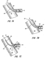
- FIGS. 7A-C schematically illustrates how a medical device 10, generally as outlined above, can be used to occlude a vessel having a wall surrounding an aperture to a vessel, channel, lumen, or cavity which is to be occluded.
- the device 10, in it's collapsed for delivery configuration and attached to the delivery system 28, can be passed through a delivery catheter 29 such that the distal end of the delivery catheter is adjacent the aperture 30 in the vessel wall 31 as shown in Fig. 7A .
- the delivery system 28 is advanced distally while holding back the delivery catheter 29 to urge the distal end of the device 10 out from the catheter 29 to elastically self expand substantially to its predetermined heat set molded state, where by it contacts the vessel wall.
- the distal end of catheter 29 may react to the expansion force and move proximally a small amount as shown in figure 7B .
- the hooks 20 begin to make contact with the vessel wall to hold the device in place. If needed to be positioned distally this can be done because the hooks will release in that direction.
- Figure 7C the device is full exited from the catheter 29 but still attached to the delivery system 28. As shown in this figure the disk 14 self aligns with the wall 31 by pivoting about the small diameter H. After the device is positioned as desired, the delivery system is disconnected by turning the delivery system 28 in a direction to release the threaded connection at the proximal end clamp 16.
- the body portion 12 should be sized so that it will frictionally engage the lumen of the vessel to be occluded.
- the device 10 will then be held in place by the combination of the friction between the body portion and the lumen of the vessel and the hooks 20 which engage the wall. Over a relatively short period of time, thrombi will form in and on the device 10 and the thrombi will occlude the vessel.
- the device may be coated with a suitable thrombogenic agent, filled with a polyester fiber or braided with an increased number of wire strands.
- Pulmonary vascular occlusive disease and pulmonary atrial hypertension develops in adulthood.
- Patients with secundum atrial septal defect (ASD) with a significant shunt are operated upon ideally at five years of age or whenever a diagnosis is made in later years.
- ASD secundum atrial septal defect
- the size of the defect will correspond to the selected size of the ASD occlusive device to be used.
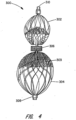
- FIGS. 2 through 4 illustrate an alternate preferred embodiment of a medical occlusive device for correcting an ASD. It is proposed that this device 300 may also be well suited in occluding defects known in the art as patent foraman ovale (hereinafter PFO) or for ventricular septal defects (VSD). With reference to FIGS. 2-4 , the device 300 in its relaxed, unstretched state has two disks 302 and 304 aligned in spaced relation, linked together by a short cylinder 306. The length of the cylindrical segment 306 preferably approximates the thickness of the atrial septum, and ranges between 2 to 20 mm.
- PFO patent foraman ovale
- VSD ventricular septal defects
- the proximal 302 and distal 304 disks preferably have an outer diameter sufficiently larger than the shunt to prevent dislodging of the device.
- the proximal disk 302 has a relatively flat configuration, whereas the distal disk 304 is cupped towards the proximal end slightly overlapping the proximal disk 302.
- FIG 3 is a cross-sectional view of the device of FIG 2 .
- the fabric of the short cylinder 306 connected with the inside wall fabric of each disk at the diameter of the short cylinder.
- the short cylinder connects with the disk walls at a small diameter 309 which is much smaller than the diameter of the short cylinder which is much smaller than the diameter of the disk. This allows the disk to easily pivot about diameter 309 to allow the disks to align themselves with anatomical vessel walls that are not perpendicular (at an angle) to the aperture there between.
- the ends of this braided metal fabric device 300 are welded or clamped together with clamps 308 and 310, as described above, to avoid fraying. Of course the ends may alternately be held together by other means readily known to those skilled in the art.
- the clamp 310 tying together the wire strands at the proximal end also serves to connect the device to a delivery system.
- the clamp 310 is generally cylindrical in shape and has a recess for receiving the ends of the metal fabric to substantially prevent the wires comprising the woven fabric from moving relative to one another.
- the clamp 310 also has a threaded surface within the recess. The threaded recess is adapted to receive and engage the threaded distal end of a delivery device 28 ( FIG. 6 ).
- the ASD occlusion device 300 of this embodiment can advantageously be made in accordance with the method outlined above.
- the device 300 is preferably made from a 0.005 inch Nitinol wire mesh.
- the braiding of the wire mesh may be carried out with 28 picks per inch at a shield angle of about 64 degrees using a Maypole braider with 72 wire carriers.
- the stiffness of the ASD device 300 may be increased or decreased by altering the wire size, the shield angle, the pick size, the number of wire carriers or the heat treatment process.
- the cavities of the mold must be shaped consistent with the desired shape of the ASD device.
- the mold In the case of the improvement the mold must be shaped to provide for forming the small pivot diameter 309.
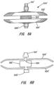
- FIGS. 8A through 8C illustrate an ASD device having a modified configuration.
- the proximal disk 302 is a mirror image of distal disk 304'.
- the distance separating the proximal and distal disks 302' and 304' is less than the length of the cylindrical segment 306.
- the cup shape of the disk as illustrated in FIG. 8B , ensures complete contact between the occlusion device 300' and the atrial septum. As such, a neo endocardium layer of endothelial tissue forms over the occlusion device 300, thereby reducing the chance of bacterial endocarditis.
- the device may be coated with a suitable thrombogenic agent, filled with a polyester fiber or braided with an increased number of wire strands.
- a polyester fiber 303 (as shown in FIGs. 4 and 8c ) is optionally placed within the braided device to speed the clotting process. This fiber easily collapses with the device for delivery through a catheter and can be placed in the disks, or middle portions or a combination of portions.
- the interwoven fiber by attachment to clot retains the clot firmly within the device as it forms the occlusion.
- the device may be delivered and properly placed using two dimensional echocardiography and Doppler color flow mapping.
- the delivery device 28 of FIG. 7C can take any suitable shape, preferably comprising an elongated flexible metal shaft similar to a conventional guidewire or may be a hollow shaft similar 27 as described for FIG. 6 above.
- the delivery device 28 is used to advance the ASD occlusion device 300 through the lumen 25 of a small diameter cylindrical tube, such as a delivery catheter 29 for deployment.
- the ASD device 300' is loaded into the lumen 25 by stretching the same to put it in an elongated condition.
- the device may be inserted into the lumen 25 during the procedure or preassembled at a manufacturing facility, in that the devices do not take on a permanent set when maintained in a compressed state.
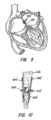
- FIG. 10 illustrates how the disks 302' and 304' can assume a non-parallel relationship to intimately engage opposed walls of a septum 318 of non-uniform thickness and with the central cylindrical portion 306' expanded against the walls defining the ASD.
- FIG. 10 depicts the device 300' occluding an ASK in the heart.
- the delivery catheter 29 is passed across the ASD.
- the device 300' is advanced through the delivery catheter until the distal end 304' becomes unconstrained on exiting the end of the catheter, whereupon it assumes its disk-like shape in the left atrium.
- the delivery catheter 29 is then pulled back in the proximal direction across the ASD and the delivery device 28 is held stationary, urging the distal disk 304' against the septum 318.
- the delivery catheter 29 is then further pulled away from the septum 318, allowing the proximal disk 302' to extend out of the delivery catheter 29, where it resiliently returns to its predefined expanded disk-like shape.
- the ASD device 300' is positioned such that the distal disk 304' presses against one side of the septum 318 while the proximal disk 302' presses against the other side of the septum 318.
- the device can contain polyester fibers 303'. (See FIG. 8C .)
- the device 300' may be recovered by pulling the delivery device 28 proximally, thereby retracting the device 300' back into the delivery catheter 29 prior to a second attempt at positioning the device 300' relative to the defect.
- the physician rotates the delivery device 28, unscrewing the delivery device 28 from the clamp 310' of the occluding device 300'.
- the threads on the clamp 310' are such that the rotation of the delivery device 28 unscrews the delivery device from the clamp 310' of the occluding device 300', rather than merely rotating the occluding device 300'.
- the threaded clamp can enable the operator to maintain a hold on the device during deployment, or enables the operator to control the spring action during deployment of the device to ensure proper positioning.
- the method disclosed further includes a method of treating a physiological condition of a patient.
- the methods disclosed do not form part of the claimed invention.
- a medical device suitable for treating the condition which may be substantially in accordance with one of the embodiments described in detail above, is selected.
- the PDA occlusion device 10 of FIGS. 5A , 5B and 6 can be selected.
- a catheter may be positioned within a channel in patient's body to place the distal end of the catheter adjacent the desired treatment site, such as immediately adjacent (or even within) the passageway or channel of the PDA.
- the medical device can be collapsed into its collapsed configuration and inserted into the lumen of the catheter.
- the collapsed configuration of the device may be of any shape suitable for easy passage through the lumen of a catheter and proper deployment out the distal end of the catheter.
- the devices shown in FIGS. 2 , 3 , 4 , 5A , 5B , 6 and 8A-8C have a relatively elongated collapsed configuration wherein the devices are stretched along their axes as shown in FIGS. 4 and 8C .
- This collapsed configuration can be achieved simply by stretching the device generally along its axis, e.g.
- the PDA occlusion device 10 of FIGS. 2 and 3 also operates in much the same fashion and can be collapsed into its collapsed configuration for insertion into the catheter by applying tension generally along the axis of the device.
- these devices 10 and 300 are not unlike "Chinese handcuffs", which tend to constrict in diameter under axial tension.
- the medical device Once the medical device is collapsed and inserted into the catheter, it may be urged along the lumen of the catheter toward the distal end of the catheter. This may be accomplished by using a delivery system or the like removably connected to the device to urge it along the catheter.
- a delivery system or the like removably connected to the device to urge it along the catheter.
- the device When the device begins to exit the distal end of the catheter, which is positioned adjacent the desired treatment site, it will tend to resiliently return substantially entirely to its preset expanded configuration.
- Superelastic alloys, such as Nitinol are particularly useful in this application because of their ability to readily return to a particular configuration after being elastically deformed to a great extent. Hence, simply urging the medical device out of the distal end of the catheter tends to properly deploy the device at the treatment site.
- the device will tend to resiliently return to its initial expanded configuration (i.e. its shape prior to being collapsed for passage through the catheter), it should be understood that it may not always return entirely to that shape.
- the member 12 of FIG. 5A is intended to have a maximum outer diameter in its expanded configuration at least as large as and preferably larger than, the inner diameter of the lumen in which it is to be deployed. If such a device is deployed in a vessel having a small lumen, the lumen will prevent the device from completely returning to its expanded configuration. Nonetheless, the device would be properly deployed because it would engage the inner wall of the lumen to seat the device therein, as detailed above.
- the device is to be used to permanently occlude a channel in the patient's body, such as the devices 10 and 300 described above may be, one can simply disconnect the delivery system (example shown FIG. 6 ) by reversing the reversible connection to the device and retract the catheter and delivery system from the patient's body. This will leave the medical device deployed in the patient's vascular system so that it may occlude the blood vessel or other channel in the patient's body.
Landscapes
- Health & Medical Sciences (AREA)
- Life Sciences & Earth Sciences (AREA)
- Surgery (AREA)
- Veterinary Medicine (AREA)
- Engineering & Computer Science (AREA)
- Biomedical Technology (AREA)
- Heart & Thoracic Surgery (AREA)
- Animal Behavior & Ethology (AREA)
- General Health & Medical Sciences (AREA)
- Public Health (AREA)
- Nuclear Medicine, Radiotherapy & Molecular Imaging (AREA)
- Medical Informatics (AREA)
- Molecular Biology (AREA)
- Vascular Medicine (AREA)
- Reproductive Health (AREA)
- Cardiology (AREA)
- Biophysics (AREA)
- Pulmonology (AREA)
- Anesthesiology (AREA)
- Hematology (AREA)
- Oral & Maxillofacial Surgery (AREA)
- Transplantation (AREA)
- Surgical Instruments (AREA)
- Media Introduction/Drainage Providing Device (AREA)
- Prostheses (AREA)
- Materials For Medical Uses (AREA)
- Pharmaceuticals Containing Other Organic And Inorganic Compounds (AREA)
- Infusion, Injection, And Reservoir Apparatuses (AREA)
Claims (12)
- Dispositif d'occlusion (10), comprenant une pluralité de brins métalliques tissés en un tissu métallique tissé dans lequel le tissu métallique a une propriété de mémoire par laquelle le dispositif d'occlusion a tendance à revenir à une configuration prédéfinie déployée lorsqu'il n'est pas contraint, le dispositif d'occlusion comprenant une configuration déployée et une configuration repliée et ayant un moyen (16, 18) pour fixer ledit tissu métallique tissé, empêchant ainsi un effilochage des brins, ladite configuration prédéfinie déployée ayant une partie en forme de disque (14) d'un premier diamètre (A) et une partie de forme cylindrique (12) adjacente d'un second diamètre (B), les parties de disque et cylindrique (14, 12) étant reliées par un segment de transition dont le diamètre (H) est inférieur à la fois aux premier et second diamètres,
caractérisé par : la seconde partie cylindrique (12) est formée au niveau de son extrémité adjacente à la partie de disque, pour former une surface conique concave selon un angle oblique par rapport à l'axe de dispositif, la surface conique étant conçue pour permettre un déplacement de la partie cylindrique depuis une position adjacente à la partie de disque par aplatissement de cône et pour fournir ainsi une force de déploiement radial pour un maintien de dispositif sur le diamètre extérieur cylindrique et pour fournir une tension axiale entre la partie de disque et la partie cylindrique lorsqu'elles sont éloignées. - Dispositif d'occlusion selon la revendication 1, dans lequel le premier diamètre (A) est de 6 à 35 mm et le second diamètre (B) est de 2 à 28 mm, et le premier diamètre (A) est supérieur au second diamètre (B).
- Dispositif d'occlusion selon la revendication 1 ou 2, dans lequel le diamètre de transition (H) est sensiblement inférieur aux premier et second diamètres (A, B).
- Dispositif d'occlusion selon la revendication 1, dans lequel la partie en forme de disque (14) et la partie en forme de cylindre (12) comprennent chacune des fibres d'occlusion.
- Dispositif d'occlusion selon la revendication 1, comprenant en outre une pluralité de crochets sans indentations (20) s'étendant vers l'extérieur depuis la surface de la seconde partie (12) et conçus pour venir en prise de manière réversible avec la paroi de cavité à l'intérieur d'une cavité lors du déploiement de dispositif afin de résister à un mouvement du dispositif vers l'extrémité de la première partie (14).
- Dispositif d'occlusion selon la revendication 5, dans lequel les crochets comprennent des fils de nitinol souples à mémoire en forme suturés ou fixés à la partie cylindrique ou à une partie de celle-ci.
- Dispositif d'occlusion selon la revendication 1, dans lequel la première partie (14) et la seconde partie (12) sont conçues pour être contraintes à une configuration plus petite que la configuration prédéfinie déployée pour une administration à travers un cathéter vers une cavité et pour s'auto-déployer jusqu'à la configuration déployée prédéfinie lorsqu'elles ne sont pas contraintes.
- Dispositif d'occlusion selon la revendication 1, dans lequel au moins une couche de brins métalliques tressés associés aux première et seconde parties (14, 12) respectives comprend une surface conçue pour être orientée généralement transversalement au flux sanguin de manière à faciliter la formation de thrombus.
- Dispositif d'occlusion selon la revendication 5, dans lequel les éléments de crochet sont conçus pour permettre au dispositif d'être repositionné par un mouvement de dispositif à distance de l'extrémité de la partie de disque (14), opposé à la direction du crochet et d'être retiré dans un cathéter d'administration après un déploiement en dépliant de manière élastique les éléments de crochet tandis que le dispositif est ramené dans l'extrémité distale du cathéter.
- Dispositif d'occlusion selon la revendication 1, conçu pour s'étendre à une profondeur d'environ 3 mm à environ 31 mm à l'intérieur d'une cavité.
- Dispositif d'occlusion selon la revendication 3, dans lequel la première partie (14) est conçue pour fléchir de ±45 degrés par rapport à la seconde partie (12) le long d'un axe central s'étendant à travers la première partie et la seconde partie.
- Ensemble d'administration pour administrer un dispositif d'occlusion (10) selon l'une quelconque des revendications 1 à 11, l'ensemble d'administration comprenant :un dispositif d'administration (28) couplé au dispositif d'occlusion (10) selon l'une quelconque des revendications 1 à 11 ; etun cathéter (29) conçu pour recouvrir le dispositif d'administration (28) et retenir le dispositif d'occlusion à l'intérieur de celui-ci, dans lequel le cathéter peut être déplacé axialement par rapport au dispositif d'administration.
Applications Claiming Priority (5)
| Application Number | Priority Date | Filing Date | Title |
|---|---|---|---|
| US11/827,590 US8034061B2 (en) | 2007-07-12 | 2007-07-12 | Percutaneous catheter directed intravascular occlusion devices |
| EP10011146.7A EP2263553B1 (fr) | 2007-07-12 | 2007-10-31 | Dispositifs d'occlusions dirigés par cathéter percutané intravasculaire |
| EP20070254329 EP2014240B1 (fr) | 2007-07-12 | 2007-10-31 | Dispositifs d'occlusions dirigés par cathéter percutané intravasculaire |
| EP19164418.6A EP3524170B8 (fr) | 2007-07-12 | 2007-10-31 | Dispositifs d'occlusion intravasculaire dirigés par cathéter percutané |
| EP15151167.2A EP2878273B1 (fr) | 2007-07-12 | 2007-10-31 | Dispositifs d'occlusions dirigés par cathéter percutané intravasculaire |
Related Parent Applications (5)
| Application Number | Title | Priority Date | Filing Date |
|---|---|---|---|
| EP19164418.6A Division-Into EP3524170B8 (fr) | 2007-07-12 | 2007-10-31 | Dispositifs d'occlusion intravasculaire dirigés par cathéter percutané |
| EP19164418.6A Division EP3524170B8 (fr) | 2007-07-12 | 2007-10-31 | Dispositifs d'occlusion intravasculaire dirigés par cathéter percutané |
| EP20070254329 Division EP2014240B1 (fr) | 2007-07-12 | 2007-10-31 | Dispositifs d'occlusions dirigés par cathéter percutané intravasculaire |
| EP10011146.7A Division EP2263553B1 (fr) | 2007-07-12 | 2007-10-31 | Dispositifs d'occlusions dirigés par cathéter percutané intravasculaire |
| EP15151167.2A Division EP2878273B1 (fr) | 2007-07-12 | 2007-10-31 | Dispositifs d'occlusions dirigés par cathéter percutané intravasculaire |
Publications (2)
| Publication Number | Publication Date |
|---|---|
| EP3777704A1 EP3777704A1 (fr) | 2021-02-17 |
| EP3777704B1 true EP3777704B1 (fr) | 2023-05-10 |
Family
ID=38879277
Family Applications (5)
| Application Number | Title | Priority Date | Filing Date |
|---|---|---|---|
| EP19164418.6A Active EP3524170B8 (fr) | 2007-07-12 | 2007-10-31 | Dispositifs d'occlusion intravasculaire dirigés par cathéter percutané |
| EP20070254329 Revoked EP2014240B1 (fr) | 2007-07-12 | 2007-10-31 | Dispositifs d'occlusions dirigés par cathéter percutané intravasculaire |
| EP15151167.2A Active EP2878273B1 (fr) | 2007-07-12 | 2007-10-31 | Dispositifs d'occlusions dirigés par cathéter percutané intravasculaire |
| EP20192239.0A Active EP3777704B1 (fr) | 2007-07-12 | 2007-10-31 | Dispositifs d'occlusion intravasculaire dirigés par cathéter percutané |
| EP10011146.7A Active EP2263553B1 (fr) | 2007-07-12 | 2007-10-31 | Dispositifs d'occlusions dirigés par cathéter percutané intravasculaire |
Family Applications Before (3)
| Application Number | Title | Priority Date | Filing Date |
|---|---|---|---|
| EP19164418.6A Active EP3524170B8 (fr) | 2007-07-12 | 2007-10-31 | Dispositifs d'occlusion intravasculaire dirigés par cathéter percutané |
| EP20070254329 Revoked EP2014240B1 (fr) | 2007-07-12 | 2007-10-31 | Dispositifs d'occlusions dirigés par cathéter percutané intravasculaire |
| EP15151167.2A Active EP2878273B1 (fr) | 2007-07-12 | 2007-10-31 | Dispositifs d'occlusions dirigés par cathéter percutané intravasculaire |
Family Applications After (1)
| Application Number | Title | Priority Date | Filing Date |
|---|---|---|---|
| EP10011146.7A Active EP2263553B1 (fr) | 2007-07-12 | 2007-10-31 | Dispositifs d'occlusions dirigés par cathéter percutané intravasculaire |
Country Status (15)
| Country | Link |
|---|---|
| US (8) | US8034061B2 (fr) |
| EP (5) | EP3524170B8 (fr) |
| JP (3) | JP5248103B2 (fr) |
| KR (1) | KR101164479B1 (fr) |
| CN (2) | CN103381102B (fr) |
| AT (1) | ATE490733T1 (fr) |
| AU (1) | AU2007231904B2 (fr) |
| BR (1) | BRPI0704145A8 (fr) |
| CA (1) | CA2609933C (fr) |
| DE (2) | DE202007019662U1 (fr) |
| ES (3) | ES2718481T3 (fr) |
| MX (1) | MX2007014644A (fr) |
| RU (1) | RU2432128C1 (fr) |
| SG (1) | SG149740A1 (fr) |
| WO (1) | WO2009008868A1 (fr) |
Families Citing this family (138)
| Publication number | Priority date | Publication date | Assignee | Title |
|---|---|---|---|---|
| US7569066B2 (en) | 1997-07-10 | 2009-08-04 | Boston Scientific Scimed, Inc. | Methods and devices for the treatment of aneurysms |
| US20030195553A1 (en) | 2002-04-12 | 2003-10-16 | Scimed Life Systems, Inc. | System and method for retaining vaso-occlusive devices within an aneurysm |
| US9861346B2 (en) | 2003-07-14 | 2018-01-09 | W. L. Gore & Associates, Inc. | Patent foramen ovale (PFO) closure device with linearly elongating petals |
| US9039724B2 (en) * | 2004-03-19 | 2015-05-26 | Aga Medical Corporation | Device for occluding vascular defects |
| US8398670B2 (en) * | 2004-03-19 | 2013-03-19 | Aga Medical Corporation | Multi-layer braided structures for occluding vascular defects and for occluding fluid flow through portions of the vasculature of the body |
| US8777974B2 (en) | 2004-03-19 | 2014-07-15 | Aga Medical Corporation | Multi-layer braided structures for occluding vascular defects |
| US8313505B2 (en) * | 2004-03-19 | 2012-11-20 | Aga Medical Corporation | Device for occluding vascular defects |
| US8747453B2 (en) | 2008-02-18 | 2014-06-10 | Aga Medical Corporation | Stent/stent graft for reinforcement of vascular abnormalities and associated method |
| EP3150177B1 (fr) * | 2006-10-22 | 2021-06-02 | Idev Technologies, Inc. | Procédés de fixation d'extrémités de brins et dispositifs résultants |
| US8882697B2 (en) | 2006-11-07 | 2014-11-11 | Dc Devices, Inc. | Apparatus and methods to create and maintain an intra-atrial pressure relief opening |
| US9232997B2 (en) | 2006-11-07 | 2016-01-12 | Corvia Medical, Inc. | Devices and methods for retrievable intra-atrial implants |
| US20110257723A1 (en) | 2006-11-07 | 2011-10-20 | Dc Devices, Inc. | Devices and methods for coronary sinus pressure relief |
| US8460372B2 (en) | 2006-11-07 | 2013-06-11 | Dc Devices, Inc. | Prosthesis for reducing intra-cardiac pressure having an embolic filter |
| JP2010508093A (ja) | 2006-11-07 | 2010-03-18 | セラマジャー,デイヴィッド,スティーヴン | 心不全を治療するための装置及び方法 |
| US10413284B2 (en) | 2006-11-07 | 2019-09-17 | Corvia Medical, Inc. | Atrial pressure regulation with control, sensing, monitoring and therapy delivery |
| US9005242B2 (en) | 2007-04-05 | 2015-04-14 | W.L. Gore & Associates, Inc. | Septal closure device with centering mechanism |
| US8034061B2 (en) | 2007-07-12 | 2011-10-11 | Aga Medical Corporation | Percutaneous catheter directed intravascular occlusion devices |
| US20090112251A1 (en) * | 2007-07-25 | 2009-04-30 | Aga Medical Corporation | Braided occlusion device having repeating expanded volume segments separated by articulation segments |
| US8361138B2 (en) * | 2007-07-25 | 2013-01-29 | Aga Medical Corporation | Braided occlusion device having repeating expanded volume segments separated by articulation segments |
| US20090171386A1 (en) | 2007-12-28 | 2009-07-02 | Aga Medical Corporation | Percutaneous catheter directed intravascular occlusion devices |
| US9743918B2 (en) * | 2008-01-18 | 2017-08-29 | St. Jude Medical, Cardiology Division, Inc. | Percutaneous catheter directed intravascular occlusion device |
| US20130165967A1 (en) | 2008-03-07 | 2013-06-27 | W.L. Gore & Associates, Inc. | Heart occlusion devices |
| US20120029556A1 (en) | 2009-06-22 | 2012-02-02 | Masters Steven J | Sealing device and delivery system |
| US9381006B2 (en) | 2009-06-22 | 2016-07-05 | W. L. Gore & Associates, Inc. | Sealing device and delivery system |
| US8956389B2 (en) | 2009-06-22 | 2015-02-17 | W. L. Gore & Associates, Inc. | Sealing device and delivery system |
| US9757107B2 (en) | 2009-09-04 | 2017-09-12 | Corvia Medical, Inc. | Methods and devices for intra-atrial shunts having adjustable sizes |
| AU2011210741B2 (en) * | 2010-01-29 | 2013-08-15 | Corvia Medical, Inc. | Devices and methods for reducing venous pressure |
| JP5730909B2 (ja) | 2010-01-29 | 2015-06-10 | ディーシー ディヴァイシーズ インコーポレイテッド | 心不全を治療するためのデバイス及びシステム |
| EP2387950A1 (fr) | 2010-05-23 | 2011-11-23 | Occlutech Holding AG | Implant médical et son procédé de fabrication |
| EP2387951B1 (fr) * | 2010-05-23 | 2012-12-26 | Occlutech Holding AG | Dispositif médical tressé et son procédé de fabrication |
| US9247942B2 (en) | 2010-06-29 | 2016-02-02 | Artventive Medical Group, Inc. | Reversible tubal contraceptive device |
| WO2012002944A1 (fr) | 2010-06-29 | 2012-01-05 | Artventive Medical Group, Inc. | Réduction d'un écoulement à travers une structure tubulaire |
| US8974512B2 (en) * | 2010-09-10 | 2015-03-10 | Medina Medical, Inc. | Devices and methods for the treatment of vascular defects |
| US9149277B2 (en) | 2010-10-18 | 2015-10-06 | Artventive Medical Group, Inc. | Expandable device delivery |
| US10201336B2 (en) | 2011-03-25 | 2019-02-12 | St. Jude Medical, Cardiology Division, Inc. | Device and method for delivering a vascular device |
| US8821529B2 (en) | 2011-03-25 | 2014-09-02 | Aga Medical Corporation | Device and method for occluding a septal defect |
| US8764787B2 (en) | 2011-06-17 | 2014-07-01 | Aga Medical Corporation | Occlusion device and associated deployment method |
| US9770232B2 (en) | 2011-08-12 | 2017-09-26 | W. L. Gore & Associates, Inc. | Heart occlusion devices |
| EP2757960B1 (fr) | 2011-10-27 | 2022-06-01 | Occlutech Holding AG | Implant médical et procédé de fabrication d'un tissu 3d de fils pour former un implant médical |
| US8758389B2 (en) * | 2011-11-18 | 2014-06-24 | Aga Medical Corporation | Devices and methods for occluding abnormal openings in a patient's vasculature |
| EP2596754A1 (fr) | 2011-11-23 | 2013-05-29 | Occlutech Holding AG | Implant médical et son procédé de fabrication |
| US8951223B2 (en) | 2011-12-22 | 2015-02-10 | Dc Devices, Inc. | Methods and devices for intra-atrial shunts having adjustable sizes |
| BR112014016789A8 (pt) * | 2012-01-06 | 2017-07-04 | Inceptus Medical LLC | dispositivos de oclusão expansíveis e métodos de uso |
| US9005155B2 (en) | 2012-02-03 | 2015-04-14 | Dc Devices, Inc. | Devices and methods for treating heart failure |
| US9113890B2 (en) | 2012-02-06 | 2015-08-25 | Aga Medical Corporation | Devices and methods for occluding vascular abnormalities |
| JP5931508B2 (ja) * | 2012-03-02 | 2016-06-08 | 株式会社東芝 | 医用画像処理装置 |
| US10588611B2 (en) | 2012-04-19 | 2020-03-17 | Corvia Medical Inc. | Implant retention attachment and method of use |
| US9649480B2 (en) | 2012-07-06 | 2017-05-16 | Corvia Medical, Inc. | Devices and methods of treating or ameliorating diastolic heart failure through pulmonary valve intervention |
| US10828019B2 (en) | 2013-01-18 | 2020-11-10 | W.L. Gore & Associates, Inc. | Sealing device and delivery system |
| US9095344B2 (en) | 2013-02-05 | 2015-08-04 | Artventive Medical Group, Inc. | Methods and apparatuses for blood vessel occlusion |
| US8984733B2 (en) | 2013-02-05 | 2015-03-24 | Artventive Medical Group, Inc. | Bodily lumen occlusion |
| US10716549B2 (en) * | 2013-03-05 | 2020-07-21 | St. Jude Medical, Cardiology Division, Inc. | Medical device for treating a target site |
| US10973523B2 (en) * | 2013-03-08 | 2021-04-13 | Aga Medical Corporation | Medical device for treating a target site |
| US10028746B2 (en) * | 2013-03-08 | 2018-07-24 | St. Jude Medical, Cardiology Division, Inc. | Medical device for treating a target site |
| US9775636B2 (en) | 2013-03-12 | 2017-10-03 | Corvia Medical, Inc. | Devices, systems, and methods for treating heart failure |
| US9737308B2 (en) | 2013-06-14 | 2017-08-22 | Artventive Medical Group, Inc. | Catheter-assisted tumor treatment |
| US9737306B2 (en) | 2013-06-14 | 2017-08-22 | Artventive Medical Group, Inc. | Implantable luminal devices |
| US10149968B2 (en) | 2013-06-14 | 2018-12-11 | Artventive Medical Group, Inc. | Catheter-assisted tumor treatment |
| US9636116B2 (en) | 2013-06-14 | 2017-05-02 | Artventive Medical Group, Inc. | Implantable luminal devices |
| US10010328B2 (en) | 2013-07-31 | 2018-07-03 | NeuVT Limited | Endovascular occlusion device with hemodynamically enhanced sealing and anchoring |
| WO2015015314A2 (fr) | 2013-07-31 | 2015-02-05 | EMBA Medical Limited | Procédés et dispositifs pour embolisation endovasculaire |
| JP6661539B2 (ja) | 2013-12-20 | 2020-03-11 | テルモ株式会社 | 血管閉鎖 |
| US10675450B2 (en) | 2014-03-12 | 2020-06-09 | Corvia Medical, Inc. | Devices and methods for treating heart failure |
| US11154302B2 (en) | 2014-03-31 | 2021-10-26 | DePuy Synthes Products, Inc. | Aneurysm occlusion device |
| US11076860B2 (en) | 2014-03-31 | 2021-08-03 | DePuy Synthes Products, Inc. | Aneurysm occlusion device |
| ES2732752T3 (es) | 2014-04-30 | 2019-11-25 | Cerus Endovascular Ltd | Dispositivo de oclusión |
| US9913744B2 (en) | 2014-04-30 | 2018-03-13 | Lean Medical Technologies, Inc. | Gastrointestinal device |
| US10363043B2 (en) | 2014-05-01 | 2019-07-30 | Artventive Medical Group, Inc. | Treatment of incompetent vessels |
| US9808230B2 (en) | 2014-06-06 | 2017-11-07 | W. L. Gore & Associates, Inc. | Sealing device and delivery system |
| CN104116574A (zh) * | 2014-07-04 | 2014-10-29 | 先健科技(深圳)有限公司 | 封堵器及封堵装置 |
| CA2955389C (fr) | 2014-07-23 | 2023-04-04 | Corvia Medical, Inc. | Dispositifs et procedes de traitement d'insuffisance cardiaque |
| US10452713B2 (en) * | 2014-09-30 | 2019-10-22 | Apple Inc. | Video analysis techniques for improved editing, navigation, and summarization |
| CN104490452B (zh) * | 2014-12-19 | 2016-09-14 | 苏津自 | 一种先天性心脏病封堵器回收钳 |
| CN105796148B (zh) * | 2014-12-31 | 2018-06-05 | 先健科技(深圳)有限公司 | 左心耳封堵器 |
| US10478194B2 (en) | 2015-09-23 | 2019-11-19 | Covidien Lp | Occlusive devices |
| EP3146903B1 (fr) * | 2015-09-23 | 2019-05-08 | Lepu Medical Technology (Beijing) Co., Ltd. | Dispositif d'occlusion pour fermer un trou apical dans la paroi cardiaque |
| EP3373829A1 (fr) | 2015-11-13 | 2018-09-19 | Cardiac Pacemakers, Inc. | Fermeture d'appendice bioabsorbable atrial gauche à surface favorisant l'endothélialisation |
| US10285711B2 (en) | 2015-12-07 | 2019-05-14 | Cerus Endovascular Limited | Occlusion device |
| CN106923886B (zh) * | 2015-12-31 | 2022-04-22 | 先健科技(深圳)有限公司 | 左心耳封堵器 |
| WO2017153603A1 (fr) | 2016-03-11 | 2017-09-14 | Cerus Endovascular Limited | Dispositif d'occlusion |
| JP6937327B2 (ja) * | 2016-03-17 | 2021-09-22 | スワミナサン ジャヤラマン | 解剖学的構造の閉塞 |
| US10813644B2 (en) | 2016-04-01 | 2020-10-27 | Artventive Medical Group, Inc. | Occlusive implant and delivery system |
| CN107753068B (zh) * | 2016-08-18 | 2020-07-21 | 先健科技(深圳)有限公司 | 封堵器 |
| WO2018058033A1 (fr) | 2016-09-26 | 2018-03-29 | St. Jude Medical, Cardiology Division, Inc. | Dispositifs d'occlusion intravasculaire dirigés par cathéter percutané avec fils de stabilisation rétractables |
| EP3526379B1 (fr) | 2016-10-14 | 2021-08-11 | Inceptus Medical, LLC | Machine à tresser et ses procédés d'utilisation |
| US10531867B2 (en) | 2017-02-13 | 2020-01-14 | Muath Alanbaei | Sinus venosus atrial septal defect treatment device |
| US11395644B2 (en) | 2017-02-13 | 2022-07-26 | Gulf Medical Technologies | Sinus venosus atrial septal defect treatment device |
| KR20190115474A (ko) | 2017-02-23 | 2019-10-11 | 디퍼이 신테스 프로덕츠, 인코포레이티드 | 동맥류 장치 및 전달 시스템 |
| US11235137B2 (en) | 2017-02-24 | 2022-02-01 | Tc1 Llc | Minimally invasive methods and devices for ventricular assist device implantation |
| CN110573092B (zh) | 2017-02-24 | 2023-04-18 | 因赛普特斯医学有限责任公司 | 血管阻塞装置和方法 |
| WO2018218210A1 (fr) | 2017-05-25 | 2018-11-29 | Microvention, Inc. | Systèmes d'occlusion adhésifs |
| CN109247959B (zh) * | 2017-07-13 | 2020-07-03 | 先健科技(深圳)有限公司 | 封堵器推送装置及输送系统 |
| JP6868867B2 (ja) * | 2017-07-19 | 2021-05-12 | 国立大学法人徳島大学 | 医療用材料 |
| IL272716B2 (en) | 2017-08-21 | 2023-09-01 | Cerus Endovascular Ltd | Install a block |
| EP3459469A1 (fr) | 2017-09-23 | 2019-03-27 | Universität Zürich | Dispositif occlusif médical |
| EP3695037B1 (fr) | 2017-10-14 | 2024-03-27 | Inceptus Medical, LLC | Machine à tresser et ses procédés d'utilisation |
| EP3716868B8 (fr) | 2017-11-30 | 2024-02-14 | Boston Scientific Scimed, Inc. | Dispositifs de pose et d'occlusion pour fuite paravalvulaire |
| US10905430B2 (en) | 2018-01-24 | 2021-02-02 | DePuy Synthes Products, Inc. | Aneurysm device and delivery system |
| WO2019161072A1 (fr) | 2018-02-14 | 2019-08-22 | Boston Scientific Scimed, Inc. | Dispositif médical occlusif |
| US11596412B2 (en) | 2018-05-25 | 2023-03-07 | DePuy Synthes Products, Inc. | Aneurysm device and delivery system |
| US11058430B2 (en) | 2018-05-25 | 2021-07-13 | DePuy Synthes Products, Inc. | Aneurysm device and delivery system |
| US10939915B2 (en) | 2018-05-31 | 2021-03-09 | DePuy Synthes Products, Inc. | Aneurysm device and delivery system |
| CN110652323A (zh) * | 2018-06-28 | 2020-01-07 | 先健科技(深圳)有限公司 | 封堵器 |
| US11051825B2 (en) | 2018-08-08 | 2021-07-06 | DePuy Synthes Products, Inc. | Delivery system for embolic braid |
| US11123077B2 (en) | 2018-09-25 | 2021-09-21 | DePuy Synthes Products, Inc. | Intrasaccular device positioning and deployment system |
| US11076861B2 (en) | 2018-10-12 | 2021-08-03 | DePuy Synthes Products, Inc. | Folded aneurysm treatment device and delivery method |
| US11564692B2 (en) | 2018-11-01 | 2023-01-31 | Terumo Corporation | Occlusion systems |
| WO2020123386A1 (fr) * | 2018-12-10 | 2020-06-18 | Boston Scientific Scimed, Inc. | Implant d'auricule gauche avec ballonnet d'étanchéité |
| US11406392B2 (en) | 2018-12-12 | 2022-08-09 | DePuy Synthes Products, Inc. | Aneurysm occluding device for use with coagulating agents |
| US11272939B2 (en) | 2018-12-18 | 2022-03-15 | DePuy Synthes Products, Inc. | Intrasaccular flow diverter for treating cerebral aneurysms |
| US11134953B2 (en) | 2019-02-06 | 2021-10-05 | DePuy Synthes Products, Inc. | Adhesive cover occluding device for aneurysm treatment |
| US11337706B2 (en) | 2019-03-27 | 2022-05-24 | DePuy Synthes Products, Inc. | Aneurysm treatment device |
| US10653425B1 (en) | 2019-05-21 | 2020-05-19 | DePuy Synthes Products, Inc. | Layered braided aneurysm treatment device |
| US11672542B2 (en) | 2019-05-21 | 2023-06-13 | DePuy Synthes Products, Inc. | Aneurysm treatment with pushable ball segment |
| US11607226B2 (en) | 2019-05-21 | 2023-03-21 | DePuy Synthes Products, Inc. | Layered braided aneurysm treatment device with corrugations |
| US11413046B2 (en) | 2019-05-21 | 2022-08-16 | DePuy Synthes Products, Inc. | Layered braided aneurysm treatment device |
| US11278292B2 (en) | 2019-05-21 | 2022-03-22 | DePuy Synthes Products, Inc. | Inverting braided aneurysm treatment system and method |
| US11602350B2 (en) | 2019-12-05 | 2023-03-14 | DePuy Synthes Products, Inc. | Intrasaccular inverting braid with highly flexible fill material |
| US11497504B2 (en) | 2019-05-21 | 2022-11-15 | DePuy Synthes Products, Inc. | Aneurysm treatment with pushable implanted braid |
| CN110477969B (zh) * | 2019-07-08 | 2023-07-21 | 江苏省肿瘤医院 | 一种瘘孔封堵系统 |
| CN114206260A (zh) * | 2019-08-20 | 2022-03-18 | 霍利斯蒂克医疗公司 | 定位装置及方法 |
| US11471650B2 (en) | 2019-09-20 | 2022-10-18 | Biosense Webster (Israel) Ltd. | Mechanism for manipulating a puller wire |
| US11944315B2 (en) | 2019-09-26 | 2024-04-02 | Universität Zürich | Left atrial appendage occlusion devices |
| US11457926B2 (en) | 2019-12-18 | 2022-10-04 | DePuy Synthes Products, Inc. | Implant having an intrasaccular section and intravascular section |
| RU198197U1 (ru) * | 2020-02-10 | 2020-06-23 | Федеральное государственное бюджетное научное учреждение "Научно-исследовательский институт пушного звероводства и кролиководства имени В.А. Афанасьева" (ФГБНУ НИИПЗК) | Фистула для изучения физиологических процессов пищеварения млекопитающих |
| US11406404B2 (en) | 2020-02-20 | 2022-08-09 | Cerus Endovascular Limited | Clot removal distal protection methods |
| JP2023525675A (ja) | 2020-04-28 | 2023-06-19 | テルモ株式会社 | 閉塞システム |
| US11890135B2 (en) | 2020-07-02 | 2024-02-06 | Evalve, Inc. | Integrated imaging and device deployment platform |
| WO2022010908A1 (fr) * | 2020-07-07 | 2022-01-13 | St. Jude Medical, Cardiology Division, Inc. | Dispositifs et méthodes d'occlusion d'anormalités du système vasculaire |
| EP4420618A3 (fr) * | 2020-08-03 | 2024-09-25 | St. Jude Medical, Cardiology Division, Inc. | Dispositifs pour le traitement d'anomalies vasculaires |
| DE102020006473A1 (de) | 2020-10-21 | 2022-04-21 | Peter Osypka Stiftung Grenzach-Wyhlen, Stiftung des bürgerlichen Rechts | Verfahren zur Herstellung von Geflecht-Schmuck |
| WO2022232399A1 (fr) * | 2021-04-29 | 2022-11-03 | Boston Scientific Scimed, Inc. | Dispositifs, systèmes et procédés d'occlusion d'un passage anatomique |
| RU2766867C1 (ru) * | 2021-06-07 | 2022-03-16 | Сергей Петрович Семитко | Устройство для перекрытия просвета сосуда, способ его изготовления и способ его доставки к целевому участку |
| RU206863U1 (ru) * | 2021-06-07 | 2021-09-30 | Сергей Петрович Семитко | Окклюдер |
| JP2023032559A (ja) * | 2021-08-27 | 2023-03-09 | グンゼ株式会社 | 医療用材料 |
| KR102637024B1 (ko) * | 2021-11-10 | 2024-02-15 | 서울대학교산학협력단 | 동물의 동맥관 개존증의 치료를 위한 카테터와 오클루더 및 이를 포함하는 폐색 기구 |
| CN115120305B (zh) * | 2022-07-13 | 2024-04-30 | 苏州中天医疗器械科技有限公司 | 一种取栓装置及取栓系统 |
| CN116077126B (zh) * | 2023-02-15 | 2024-05-07 | 晨兴(南通)医疗器械有限公司 | 血管封堵器及其制作方法和安装方法 |
Family Cites Families (59)
| Publication number | Priority date | Publication date | Assignee | Title |
|---|---|---|---|---|
| US3874388A (en) | 1973-02-12 | 1975-04-01 | Ochsner Med Found Alton | Shunt defect closure system |
| US4007743A (en) | 1975-10-20 | 1977-02-15 | American Hospital Supply Corporation | Opening mechanism for umbrella-like intravascular shunt defect closure device |
| DK151404C (da) | 1984-05-23 | 1988-07-18 | Cook Europ Aps William | Sammenklappeligt filter til implantation i en patients blodkar |
| SU1468511A1 (ru) | 1987-02-17 | 1989-03-30 | Целиноградский государственный медицинский институт | Устройство дл фиксации |
| US4836204A (en) | 1987-07-06 | 1989-06-06 | Landymore Roderick W | Method for effecting closure of a perforation in the septum of the heart |
| US4921484A (en) | 1988-07-25 | 1990-05-01 | Cordis Corporation | Mesh balloon catheter device |
| US5067489A (en) | 1988-08-16 | 1991-11-26 | Flexmedics Corporation | Flexible guide with safety tip |
| US4917089A (en) | 1988-08-29 | 1990-04-17 | Sideris Eleftherios B | Buttoned device for the transvenous occlusion of intracardiac defects |
| JP2754067B2 (ja) | 1989-01-17 | 1998-05-20 | 日本ゼオン株式会社 | 医療用体壁穴栓塞治具 |
| US4991602A (en) | 1989-06-27 | 1991-02-12 | Flexmedics Corporation | Flexible guide wire with safety tip |
| WO1991015155A1 (fr) | 1990-04-02 | 1991-10-17 | Kanji Inoue | Procede pour refermer une ouverture de shunt au moyen d'un procede sans operateur |
| US5064435A (en) | 1990-06-28 | 1991-11-12 | Schneider (Usa) Inc. | Self-expanding prosthesis having stable axial length |
| US5108420A (en) | 1991-02-01 | 1992-04-28 | Temple University | Aperture occlusion device |
| AU2323692A (en) | 1991-07-09 | 1993-02-11 | Automotive Technologies International, Inc. | Improved tape switch crush sensor |
| DE69229539T2 (de) | 1991-11-05 | 2000-02-17 | Children's Medical Center Corp., Boston | Okklusionsvorrichtung zur Reparatur von Herz- und Gefäss-Defekten |
| CA2082090C (fr) | 1991-11-05 | 2004-04-27 | Jack Fagan | Dispositif d'occlusion pour la reparation des anomalies cardiaques et vasculaires |
| EP0614342B1 (fr) | 1991-11-29 | 1999-07-14 | William Cook Europe A/S | Prothese de fermeture a mettre en place par l'intermediaire d'un catheter |
| DE69324239T2 (de) | 1992-01-21 | 1999-11-04 | The Regents Of The University Of Minnesota, Minneapolis | Verschlusseinrichtung eines septumschadens |
| WO1994006460A1 (fr) | 1992-09-21 | 1994-03-31 | Vitaphore Corporation | Bouchons d'embolisation pour vaisseaux sanguins |
| US5382259A (en) | 1992-10-26 | 1995-01-17 | Target Therapeutics, Inc. | Vasoocclusion coil with attached tubular woven or braided fibrous covering |
| US5466242A (en) | 1994-02-02 | 1995-11-14 | Mori; Katsushi | Stent for biliary, urinary or vascular system |
| US6123715A (en) | 1994-07-08 | 2000-09-26 | Amplatz; Curtis | Method of forming medical devices; intravascular occlusion devices |
| US5846261A (en) * | 1994-07-08 | 1998-12-08 | Aga Medical Corp. | Percutaneous catheter directed occlusion devices |
| US5725552A (en) * | 1994-07-08 | 1998-03-10 | Aga Medical Corporation | Percutaneous catheter directed intravascular occlusion devices |
| US5879366A (en) | 1996-12-20 | 1999-03-09 | W.L. Gore & Associates, Inc. | Self-expanding defect closure device and method of making and using |
| US5846216A (en) * | 1995-04-06 | 1998-12-08 | G & P Technologies, Inc. | Mucous membrane infusor and method of use for dispensing medications |
| FI103263B (fi) | 1996-01-02 | 1999-05-31 | Haapasalo Pauli | Sahakoneen terälaite |
| US6168622B1 (en) | 1996-01-24 | 2001-01-02 | Microvena Corporation | Method and apparatus for occluding aneurysms |
| GB9614950D0 (en) * | 1996-07-16 | 1996-09-04 | Anson Medical Ltd | A ductus stent and delivery catheter |
| GB9716497D0 (en) * | 1997-08-05 | 1997-10-08 | Bridport Gundry Plc | Occlusion device |
| US6020222A (en) | 1997-12-16 | 2000-02-01 | Advanced Micro Devices, Inc. | Silicon oxide insulator (SOI) semiconductor having selectively linked body |
| US5944738A (en) * | 1998-02-06 | 1999-08-31 | Aga Medical Corporation | Percutaneous catheter directed constricting occlusion device |
| JP2002521948A (ja) | 1998-07-31 | 2002-07-16 | ビテッセ セミコンダクター コーポレイション | 多相補間lc電圧制御発振器 |
| US6375668B1 (en) * | 1999-06-02 | 2002-04-23 | Hanson S. Gifford | Devices and methods for treating vascular malformations |
| JP4378800B2 (ja) | 1999-08-09 | 2009-12-09 | 株式会社ニコン | 表示装置、該表示装置を備えたカメラ |
| US6652555B1 (en) | 1999-10-27 | 2003-11-25 | Atritech, Inc. | Barrier device for covering the ostium of left atrial appendage |
| US6689150B1 (en) * | 1999-10-27 | 2004-02-10 | Atritech, Inc. | Filter apparatus for ostium of left atrial appendage |
| US6468303B1 (en) | 2000-03-27 | 2002-10-22 | Aga Medical Corporation | Retrievable self expanding shunt |
| US6214029B1 (en) | 2000-04-26 | 2001-04-10 | Microvena Corporation | Septal defect occluder |
| US6551344B2 (en) | 2000-04-26 | 2003-04-22 | Ev3 Inc. | Septal defect occluder |
| JP2002043224A (ja) | 2000-07-18 | 2002-02-08 | Applied Materials Inc | アダプター、チャンバ及びプラズマ処理装置 |
| JP3988364B2 (ja) | 2000-08-02 | 2007-10-10 | オムロン株式会社 | セーフティスイッチ |
| US20030057156A1 (en) * | 2001-03-08 | 2003-03-27 | Dean Peterson | Atrial filter implants |
| JP2003051212A (ja) | 2001-05-29 | 2003-02-21 | Denso Corp | 車両用前照灯 |
| JP2003190175A (ja) * | 2001-11-15 | 2003-07-08 | Cordis Neurovascular Inc | 動脈瘤を密閉するための動脈瘤頚部プラグ |
| US6638257B2 (en) | 2002-03-01 | 2003-10-28 | Aga Medical Corporation | Intravascular flow restrictor |
| AU2003240549A1 (en) * | 2002-06-05 | 2003-12-22 | Nmt Medical, Inc. | Patent foramen ovale (pfo) closure device with radial and circumferential support |
| US7087072B2 (en) * | 2003-01-22 | 2006-08-08 | Cardia, Inc. | Articulated center post |
| EP1648311A4 (fr) * | 2003-06-27 | 2010-11-17 | Conceptus Inc | Procedes et dispositifs d'occlusion d'une lumiere corporelle et/ou d'administration d'agents therapeutiques |
| US6991037B2 (en) | 2003-12-30 | 2006-01-31 | Geosierra Llc | Multiple azimuth control of vertical hydraulic fractures in unconsolidated and weakly cemented sediments |
| US20050228434A1 (en) * | 2004-03-19 | 2005-10-13 | Aga Medical Corporation | Multi-layer braided structures for occluding vascular defects |
| US8777974B2 (en) * | 2004-03-19 | 2014-07-15 | Aga Medical Corporation | Multi-layer braided structures for occluding vascular defects |
| ES2551618T3 (es) | 2004-04-08 | 2015-11-20 | Aga Medical Corporation | Dispositivos de oclusión embridados. |
| JP2005050820A (ja) | 2004-08-25 | 2005-02-24 | Ibiden Co Ltd | ホットプレート |
| US7972359B2 (en) * | 2005-09-16 | 2011-07-05 | Atritech, Inc. | Intracardiac cage and method of delivering same |
| US10143456B2 (en) * | 2005-10-07 | 2018-12-04 | Alex Javois | Left atrial appendage occlusion device |
| US7665466B2 (en) * | 2005-11-14 | 2010-02-23 | Occlutech Gmbh | Self-expanding medical occlusion device |
| US20080051830A1 (en) * | 2006-08-24 | 2008-02-28 | Boston Scientific Scimed, Inc. | Occluding device and method |
| US8034061B2 (en) * | 2007-07-12 | 2011-10-11 | Aga Medical Corporation | Percutaneous catheter directed intravascular occlusion devices |
-
2007
- 2007-07-12 US US11/827,590 patent/US8034061B2/en active Active
- 2007-09-05 WO PCT/US2007/019347 patent/WO2009008868A1/fr active Application Filing
- 2007-09-05 KR KR20097026325A patent/KR101164479B1/ko active IP Right Grant
- 2007-09-05 CN CN201310234477.1A patent/CN103381102B/zh not_active Ceased
- 2007-09-05 RU RU2010104839A patent/RU2432128C1/ru not_active IP Right Cessation
- 2007-09-05 CN CN200780100580XA patent/CN101795628B/zh active Active
- 2007-10-31 EP EP19164418.6A patent/EP3524170B8/fr active Active
- 2007-10-31 EP EP20070254329 patent/EP2014240B1/fr not_active Revoked
- 2007-10-31 DE DE200720019662 patent/DE202007019662U1/de not_active Expired - Lifetime
- 2007-10-31 DE DE200760011049 patent/DE602007011049D1/de active Active
- 2007-10-31 ES ES10011146T patent/ES2718481T3/es active Active
- 2007-10-31 ES ES20192239T patent/ES2946358T3/es active Active
- 2007-10-31 EP EP15151167.2A patent/EP2878273B1/fr active Active
- 2007-10-31 EP EP20192239.0A patent/EP3777704B1/fr active Active
- 2007-10-31 EP EP10011146.7A patent/EP2263553B1/fr active Active
- 2007-10-31 ES ES19164418T patent/ES2832559T3/es active Active
- 2007-10-31 AT AT07254329T patent/ATE490733T1/de not_active IP Right Cessation
- 2007-11-01 SG SG200717407-1A patent/SG149740A1/en unknown
- 2007-11-05 BR BRPI0704145A patent/BRPI0704145A8/pt not_active Application Discontinuation
- 2007-11-07 CA CA2609933A patent/CA2609933C/fr active Active
- 2007-11-09 AU AU2007231904A patent/AU2007231904B2/en active Active
- 2007-11-22 MX MX2007014644A patent/MX2007014644A/es active IP Right Grant
- 2007-12-27 JP JP2007337174A patent/JP5248103B2/ja active Active
-
2011
- 2011-08-24 US US13/216,784 patent/US8454633B2/en active Active
-
2013
- 2013-03-15 US US13/837,351 patent/US8961556B2/en active Active
- 2013-04-10 JP JP2013082265A patent/JP5964778B2/ja active Active
-
2015
- 2015-01-09 US US14/593,039 patent/US10149669B2/en active Active
- 2015-02-02 JP JP2015018494A patent/JP6006348B2/ja active Active
-
2018
- 2018-11-02 US US16/179,503 patent/US11116486B2/en active Active
-
2021
- 2021-07-26 US US17/384,874 patent/US11925338B2/en active Active
- 2021-08-20 US US17/407,736 patent/US12114844B2/en active Active
-
2024
- 2024-06-25 US US18/753,059 patent/US20240341740A1/en active Pending
Also Published As
Similar Documents
| Publication | Publication Date | Title |
|---|---|---|
| US11925338B2 (en) | Percutaneous catheter directed intravascular occlusion devices | |
| US11317920B2 (en) | Percutaneous catheter directed intravascular occlusion devices | |
| AU2013270508B2 (en) | Percutaneous catheter directed intravascular occlusion devices |
Legal Events
| Date | Code | Title | Description |
|---|---|---|---|
| PUAI | Public reference made under article 153(3) epc to a published international application that has entered the european phase |
Free format text: ORIGINAL CODE: 0009012 |
|
| STAA | Information on the status of an ep patent application or granted ep patent |
Free format text: STATUS: REQUEST FOR EXAMINATION WAS MADE |
|
| 17P | Request for examination filed |
Effective date: 20200824 |
|
| AC | Divisional application: reference to earlier application |
Ref document number: 3524170 Country of ref document: EP Kind code of ref document: P Ref document number: 2263553 Country of ref document: EP Kind code of ref document: P Ref document number: 2014240 Country of ref document: EP Kind code of ref document: P Ref document number: 2878273 Country of ref document: EP Kind code of ref document: P |
|
| AK | Designated contracting states |
Kind code of ref document: A1 Designated state(s): AT BE BG CH CY CZ DE DK EE ES FI FR GB GR HU IE IS IT LI LT LU LV MC MT NL PL PT RO SE SI SK TR |
|
| STAA | Information on the status of an ep patent application or granted ep patent |
Free format text: STATUS: EXAMINATION IS IN PROGRESS |
|
| 17Q | First examination report despatched |
Effective date: 20211025 |
|
| GRAP | Despatch of communication of intention to grant a patent |
Free format text: ORIGINAL CODE: EPIDOSNIGR1 |
|
| STAA | Information on the status of an ep patent application or granted ep patent |
Free format text: STATUS: GRANT OF PATENT IS INTENDED |
|
| INTG | Intention to grant announced |
Effective date: 20220708 |
|
| GRAJ | Information related to disapproval of communication of intention to grant by the applicant or resumption of examination proceedings by the epo deleted |
Free format text: ORIGINAL CODE: EPIDOSDIGR1 |
|
| STAA | Information on the status of an ep patent application or granted ep patent |
Free format text: STATUS: EXAMINATION IS IN PROGRESS |
|
| INTC | Intention to grant announced (deleted) | ||
| GRAP | Despatch of communication of intention to grant a patent |
Free format text: ORIGINAL CODE: EPIDOSNIGR1 |
|
| STAA | Information on the status of an ep patent application or granted ep patent |
Free format text: STATUS: GRANT OF PATENT IS INTENDED |
|
| INTG | Intention to grant announced |
Effective date: 20230103 |
|
| GRAS | Grant fee paid |
Free format text: ORIGINAL CODE: EPIDOSNIGR3 |
|
| GRAA | (expected) grant |
Free format text: ORIGINAL CODE: 0009210 |
|
| STAA | Information on the status of an ep patent application or granted ep patent |
Free format text: STATUS: THE PATENT HAS BEEN GRANTED |
|
| AC | Divisional application: reference to earlier application |
Ref document number: 2014240 Country of ref document: EP Kind code of ref document: P Ref document number: 2263553 Country of ref document: EP Kind code of ref document: P Ref document number: 2878273 Country of ref document: EP Kind code of ref document: P Ref document number: 3524170 Country of ref document: EP Kind code of ref document: P |
|
| AK | Designated contracting states |
Kind code of ref document: B1 Designated state(s): AT BE BG CH CY CZ DE DK EE ES FI FR GB GR HU IE IS IT LI LT LU LV MC MT NL PL PT RO SE SI SK TR |
|
| REG | Reference to a national code |
Ref country code: GB Ref legal event code: FG4D |
|
| REG | Reference to a national code |
Ref country code: AT Ref legal event code: REF Ref document number: 1565968 Country of ref document: AT Kind code of ref document: T Effective date: 20230515 Ref country code: CH Ref legal event code: EP |
|
| REG | Reference to a national code |
Ref country code: DE Ref legal event code: R096 Ref document number: 602007061666 Country of ref document: DE |
|
| REG | Reference to a national code |
Ref country code: IE Ref legal event code: FG4D |
|
| REG | Reference to a national code |
Ref country code: ES Ref legal event code: FG2A Ref document number: 2946358 Country of ref document: ES Kind code of ref document: T3 Effective date: 20230717 |
|
| P01 | Opt-out of the competence of the unified patent court (upc) registered |
Effective date: 20230616 |
|
| REG | Reference to a national code |
Ref country code: LT Ref legal event code: MG9D |
|
| REG | Reference to a national code |
Ref country code: NL Ref legal event code: MP Effective date: 20230510 |
|
| REG | Reference to a national code |
Ref country code: AT Ref legal event code: MK05 Ref document number: 1565968 Country of ref document: AT Kind code of ref document: T Effective date: 20230510 |
|
| PG25 | Lapsed in a contracting state [announced via postgrant information from national office to epo] |
Ref country code: SE Free format text: LAPSE BECAUSE OF FAILURE TO SUBMIT A TRANSLATION OF THE DESCRIPTION OR TO PAY THE FEE WITHIN THE PRESCRIBED TIME-LIMIT Effective date: 20230510 Ref country code: PT Free format text: LAPSE BECAUSE OF FAILURE TO SUBMIT A TRANSLATION OF THE DESCRIPTION OR TO PAY THE FEE WITHIN THE PRESCRIBED TIME-LIMIT Effective date: 20230911 Ref country code: NL Free format text: LAPSE BECAUSE OF FAILURE TO SUBMIT A TRANSLATION OF THE DESCRIPTION OR TO PAY THE FEE WITHIN THE PRESCRIBED TIME-LIMIT Effective date: 20230510 Ref country code: AT Free format text: LAPSE BECAUSE OF FAILURE TO SUBMIT A TRANSLATION OF THE DESCRIPTION OR TO PAY THE FEE WITHIN THE PRESCRIBED TIME-LIMIT Effective date: 20230510 |
|
| PG25 | Lapsed in a contracting state [announced via postgrant information from national office to epo] |
Ref country code: PL Free format text: LAPSE BECAUSE OF FAILURE TO SUBMIT A TRANSLATION OF THE DESCRIPTION OR TO PAY THE FEE WITHIN THE PRESCRIBED TIME-LIMIT Effective date: 20230510 Ref country code: LV Free format text: LAPSE BECAUSE OF FAILURE TO SUBMIT A TRANSLATION OF THE DESCRIPTION OR TO PAY THE FEE WITHIN THE PRESCRIBED TIME-LIMIT Effective date: 20230510 Ref country code: LT Free format text: LAPSE BECAUSE OF FAILURE TO SUBMIT A TRANSLATION OF THE DESCRIPTION OR TO PAY THE FEE WITHIN THE PRESCRIBED TIME-LIMIT Effective date: 20230510 Ref country code: IS Free format text: LAPSE BECAUSE OF FAILURE TO SUBMIT A TRANSLATION OF THE DESCRIPTION OR TO PAY THE FEE WITHIN THE PRESCRIBED TIME-LIMIT Effective date: 20230910 Ref country code: GR Free format text: LAPSE BECAUSE OF FAILURE TO SUBMIT A TRANSLATION OF THE DESCRIPTION OR TO PAY THE FEE WITHIN THE PRESCRIBED TIME-LIMIT Effective date: 20230811 |
|
| PG25 | Lapsed in a contracting state [announced via postgrant information from national office to epo] |
Ref country code: FI Free format text: LAPSE BECAUSE OF FAILURE TO SUBMIT A TRANSLATION OF THE DESCRIPTION OR TO PAY THE FEE WITHIN THE PRESCRIBED TIME-LIMIT Effective date: 20230510 |
|
| PG25 | Lapsed in a contracting state [announced via postgrant information from national office to epo] |
Ref country code: SK Free format text: LAPSE BECAUSE OF FAILURE TO SUBMIT A TRANSLATION OF THE DESCRIPTION OR TO PAY THE FEE WITHIN THE PRESCRIBED TIME-LIMIT Effective date: 20230510 |
|
| PGFP | Annual fee paid to national office [announced via postgrant information from national office to epo] |
Ref country code: ES Payment date: 20231108 Year of fee payment: 17 |
|
| PG25 | Lapsed in a contracting state [announced via postgrant information from national office to epo] |
Ref country code: SK Free format text: LAPSE BECAUSE OF FAILURE TO SUBMIT A TRANSLATION OF THE DESCRIPTION OR TO PAY THE FEE WITHIN THE PRESCRIBED TIME-LIMIT Effective date: 20230510 Ref country code: RO Free format text: LAPSE BECAUSE OF FAILURE TO SUBMIT A TRANSLATION OF THE DESCRIPTION OR TO PAY THE FEE WITHIN THE PRESCRIBED TIME-LIMIT Effective date: 20230510 Ref country code: EE Free format text: LAPSE BECAUSE OF FAILURE TO SUBMIT A TRANSLATION OF THE DESCRIPTION OR TO PAY THE FEE WITHIN THE PRESCRIBED TIME-LIMIT Effective date: 20230510 Ref country code: DK Free format text: LAPSE BECAUSE OF FAILURE TO SUBMIT A TRANSLATION OF THE DESCRIPTION OR TO PAY THE FEE WITHIN THE PRESCRIBED TIME-LIMIT Effective date: 20230510 Ref country code: CZ Free format text: LAPSE BECAUSE OF FAILURE TO SUBMIT A TRANSLATION OF THE DESCRIPTION OR TO PAY THE FEE WITHIN THE PRESCRIBED TIME-LIMIT Effective date: 20230510 |
|
| PGFP | Annual fee paid to national office [announced via postgrant information from national office to epo] |
Ref country code: IT Payment date: 20231012 Year of fee payment: 17 Ref country code: DE Payment date: 20230915 Year of fee payment: 17 |
|
| REG | Reference to a national code |
Ref country code: DE Ref legal event code: R097 Ref document number: 602007061666 Country of ref document: DE |
|
| PLBE | No opposition filed within time limit |
Free format text: ORIGINAL CODE: 0009261 |
|
| STAA | Information on the status of an ep patent application or granted ep patent |
Free format text: STATUS: NO OPPOSITION FILED WITHIN TIME LIMIT |
|
| 26N | No opposition filed |
Effective date: 20240213 |
|
| PG25 | Lapsed in a contracting state [announced via postgrant information from national office to epo] |
Ref country code: SI Free format text: LAPSE BECAUSE OF FAILURE TO SUBMIT A TRANSLATION OF THE DESCRIPTION OR TO PAY THE FEE WITHIN THE PRESCRIBED TIME-LIMIT Effective date: 20230510 |
|
| PG25 | Lapsed in a contracting state [announced via postgrant information from national office to epo] |
Ref country code: SI Free format text: LAPSE BECAUSE OF FAILURE TO SUBMIT A TRANSLATION OF THE DESCRIPTION OR TO PAY THE FEE WITHIN THE PRESCRIBED TIME-LIMIT Effective date: 20230510 Ref country code: MC Free format text: LAPSE BECAUSE OF FAILURE TO SUBMIT A TRANSLATION OF THE DESCRIPTION OR TO PAY THE FEE WITHIN THE PRESCRIBED TIME-LIMIT Effective date: 20230510 |
|
| REG | Reference to a national code |
Ref country code: CH Ref legal event code: PL |
|
| REG | Reference to a national code |
Ref country code: BE Ref legal event code: MM Effective date: 20231031 |
|
| PG25 | Lapsed in a contracting state [announced via postgrant information from national office to epo] |
Ref country code: LU Free format text: LAPSE BECAUSE OF NON-PAYMENT OF DUE FEES Effective date: 20231031 |
|
| PG25 | Lapsed in a contracting state [announced via postgrant information from national office to epo] |
Ref country code: LU Free format text: LAPSE BECAUSE OF NON-PAYMENT OF DUE FEES Effective date: 20231031 |
|
| PG25 | Lapsed in a contracting state [announced via postgrant information from national office to epo] |
Ref country code: CH Free format text: LAPSE BECAUSE OF NON-PAYMENT OF DUE FEES Effective date: 20231031 |
|
| PG25 | Lapsed in a contracting state [announced via postgrant information from national office to epo] |
Ref country code: CH Free format text: LAPSE BECAUSE OF NON-PAYMENT OF DUE FEES Effective date: 20231031 |
|
| PG25 | Lapsed in a contracting state [announced via postgrant information from national office to epo] |
Ref country code: BE Free format text: LAPSE BECAUSE OF NON-PAYMENT OF DUE FEES Effective date: 20231031 |
|
| PG25 | Lapsed in a contracting state [announced via postgrant information from national office to epo] |
Ref country code: IE Free format text: LAPSE BECAUSE OF NON-PAYMENT OF DUE FEES Effective date: 20231031 |
|
| PGFP | Annual fee paid to national office [announced via postgrant information from national office to epo] |
Ref country code: GB Payment date: 20240912 Year of fee payment: 18 |
|
| PGFP | Annual fee paid to national office [announced via postgrant information from national office to epo] |
Ref country code: FR Payment date: 20240913 Year of fee payment: 18 |