EP3768043A1 - Induktionserwärmungskocher - Google Patents
Induktionserwärmungskocher Download PDFInfo
- Publication number
- EP3768043A1 EP3768043A1 EP18909385.9A EP18909385A EP3768043A1 EP 3768043 A1 EP3768043 A1 EP 3768043A1 EP 18909385 A EP18909385 A EP 18909385A EP 3768043 A1 EP3768043 A1 EP 3768043A1
- Authority
- EP
- European Patent Office
- Prior art keywords
- heating
- heating coils
- target
- electric power
- heating coil
- Prior art date
- Legal status (The legal status is an assumption and is not a legal conclusion. Google has not performed a legal analysis and makes no representation as to the accuracy of the status listed.)
- Granted
Links
- 238000010438 heat treatment Methods 0.000 title claims abstract description 1101
- 230000006698 induction Effects 0.000 title claims abstract description 151
- 230000008859 change Effects 0.000 claims abstract description 13
- 239000003990 capacitor Substances 0.000 claims description 40
- 238000001514 detection method Methods 0.000 claims description 16
- 238000010411 cooking Methods 0.000 description 153
- 239000007788 liquid Substances 0.000 description 102
- 238000010586 diagram Methods 0.000 description 45
- 230000000694 effects Effects 0.000 description 20
- 238000000034 method Methods 0.000 description 13
- XEEYBQQBJWHFJM-UHFFFAOYSA-N Iron Chemical compound [Fe] XEEYBQQBJWHFJM-UHFFFAOYSA-N 0.000 description 12
- 230000004048 modification Effects 0.000 description 11
- 238000012986 modification Methods 0.000 description 11
- 230000002093 peripheral effect Effects 0.000 description 11
- 230000008569 process Effects 0.000 description 11
- 239000000796 flavoring agent Substances 0.000 description 6
- 235000019634 flavors Nutrition 0.000 description 6
- 229910052742 iron Inorganic materials 0.000 description 6
- 239000007787 solid Substances 0.000 description 6
- 239000004065 semiconductor Substances 0.000 description 5
- 229910052751 metal Inorganic materials 0.000 description 4
- 239000002184 metal Substances 0.000 description 4
- 230000001550 time effect Effects 0.000 description 4
- 230000006870 function Effects 0.000 description 3
- 230000035515 penetration Effects 0.000 description 3
- 230000005611 electricity Effects 0.000 description 2
- 238000009499 grossing Methods 0.000 description 2
- 230000006872 improvement Effects 0.000 description 2
- 238000004804 winding Methods 0.000 description 2
- RYGMFSIKBFXOCR-UHFFFAOYSA-N Copper Chemical compound [Cu] RYGMFSIKBFXOCR-UHFFFAOYSA-N 0.000 description 1
- 229910002601 GaN Inorganic materials 0.000 description 1
- JMASRVWKEDWRBT-UHFFFAOYSA-N Gallium nitride Chemical compound [Ga]#N JMASRVWKEDWRBT-UHFFFAOYSA-N 0.000 description 1
- XUIMIQQOPSSXEZ-UHFFFAOYSA-N Silicon Chemical compound [Si] XUIMIQQOPSSXEZ-UHFFFAOYSA-N 0.000 description 1
- ATJFFYVFTNAWJD-UHFFFAOYSA-N Tin Chemical compound [Sn] ATJFFYVFTNAWJD-UHFFFAOYSA-N 0.000 description 1
- 229910052782 aluminium Inorganic materials 0.000 description 1
- XAGFODPZIPBFFR-UHFFFAOYSA-N aluminium Chemical compound [Al] XAGFODPZIPBFFR-UHFFFAOYSA-N 0.000 description 1
- 238000009835 boiling Methods 0.000 description 1
- 239000011248 coating agent Substances 0.000 description 1
- 238000000576 coating method Methods 0.000 description 1
- 239000002131 composite material Substances 0.000 description 1
- 229910052802 copper Inorganic materials 0.000 description 1
- 239000010949 copper Substances 0.000 description 1
- 230000008878 coupling Effects 0.000 description 1
- 238000010168 coupling process Methods 0.000 description 1
- 238000005859 coupling reaction Methods 0.000 description 1
- 230000004907 flux Effects 0.000 description 1
- 239000011521 glass Substances 0.000 description 1
- 230000017525 heat dissipation Effects 0.000 description 1
- 239000004973 liquid crystal related substance Substances 0.000 description 1
- 238000004519 manufacturing process Methods 0.000 description 1
- 230000003287 optical effect Effects 0.000 description 1
- 230000001737 promoting effect Effects 0.000 description 1
- 230000009467 reduction Effects 0.000 description 1
- 229910052710 silicon Inorganic materials 0.000 description 1
- 239000010703 silicon Substances 0.000 description 1
- HBMJWWWQQXIZIP-UHFFFAOYSA-N silicon carbide Chemical compound [Si+]#[C-] HBMJWWWQQXIZIP-UHFFFAOYSA-N 0.000 description 1
- 229910010271 silicon carbide Inorganic materials 0.000 description 1
- 239000005341 toughened glass Substances 0.000 description 1
- 239000012780 transparent material Substances 0.000 description 1
- XLYOFNOQVPJJNP-UHFFFAOYSA-N water Substances O XLYOFNOQVPJJNP-UHFFFAOYSA-N 0.000 description 1
Images


Classifications
-
- H—ELECTRICITY
- H05—ELECTRIC TECHNIQUES NOT OTHERWISE PROVIDED FOR
- H05B—ELECTRIC HEATING; ELECTRIC LIGHT SOURCES NOT OTHERWISE PROVIDED FOR; CIRCUIT ARRANGEMENTS FOR ELECTRIC LIGHT SOURCES, IN GENERAL
- H05B6/00—Heating by electric, magnetic or electromagnetic fields
- H05B6/02—Induction heating
- H05B6/06—Control, e.g. of temperature, of power
- H05B6/062—Control, e.g. of temperature, of power for cooking plates or the like
- H05B6/065—Control, e.g. of temperature, of power for cooking plates or the like using coordinated control of multiple induction coils
-
- H—ELECTRICITY
- H02—GENERATION; CONVERSION OR DISTRIBUTION OF ELECTRIC POWER
- H02M—APPARATUS FOR CONVERSION BETWEEN AC AND AC, BETWEEN AC AND DC, OR BETWEEN DC AND DC, AND FOR USE WITH MAINS OR SIMILAR POWER SUPPLY SYSTEMS; CONVERSION OF DC OR AC INPUT POWER INTO SURGE OUTPUT POWER; CONTROL OR REGULATION THEREOF
- H02M7/00—Conversion of ac power input into dc power output; Conversion of dc power input into ac power output
- H02M7/42—Conversion of dc power input into ac power output without possibility of reversal
- H02M7/44—Conversion of dc power input into ac power output without possibility of reversal by static converters
- H02M7/48—Conversion of dc power input into ac power output without possibility of reversal by static converters using discharge tubes with control electrode or semiconductor devices with control electrode
- H02M7/53—Conversion of dc power input into ac power output without possibility of reversal by static converters using discharge tubes with control electrode or semiconductor devices with control electrode using devices of a triode or transistor type requiring continuous application of a control signal
- H02M7/537—Conversion of dc power input into ac power output without possibility of reversal by static converters using discharge tubes with control electrode or semiconductor devices with control electrode using devices of a triode or transistor type requiring continuous application of a control signal using semiconductor devices only, e.g. single switched pulse inverters
-
- H—ELECTRICITY
- H05—ELECTRIC TECHNIQUES NOT OTHERWISE PROVIDED FOR
- H05B—ELECTRIC HEATING; ELECTRIC LIGHT SOURCES NOT OTHERWISE PROVIDED FOR; CIRCUIT ARRANGEMENTS FOR ELECTRIC LIGHT SOURCES, IN GENERAL
- H05B6/00—Heating by electric, magnetic or electromagnetic fields
- H05B6/02—Induction heating
- H05B6/10—Induction heating apparatus, other than furnaces, for specific applications
- H05B6/12—Cooking devices
- H05B6/1209—Cooking devices induction cooking plates or the like and devices to be used in combination with them
- H05B6/1245—Cooking devices induction cooking plates or the like and devices to be used in combination with them with special coil arrangements
- H05B6/1272—Cooking devices induction cooking plates or the like and devices to be used in combination with them with special coil arrangements with more than one coil or coil segment per heating zone
-
- H—ELECTRICITY
- H05—ELECTRIC TECHNIQUES NOT OTHERWISE PROVIDED FOR
- H05B—ELECTRIC HEATING; ELECTRIC LIGHT SOURCES NOT OTHERWISE PROVIDED FOR; CIRCUIT ARRANGEMENTS FOR ELECTRIC LIGHT SOURCES, IN GENERAL
- H05B2213/00—Aspects relating both to resistive heating and to induction heating, covered by H05B3/00 and H05B6/00
- H05B2213/05—Heating plates with pan detection means
-
- Y—GENERAL TAGGING OF NEW TECHNOLOGICAL DEVELOPMENTS; GENERAL TAGGING OF CROSS-SECTIONAL TECHNOLOGIES SPANNING OVER SEVERAL SECTIONS OF THE IPC; TECHNICAL SUBJECTS COVERED BY FORMER USPC CROSS-REFERENCE ART COLLECTIONS [XRACs] AND DIGESTS
- Y02—TECHNOLOGIES OR APPLICATIONS FOR MITIGATION OR ADAPTATION AGAINST CLIMATE CHANGE
- Y02B—CLIMATE CHANGE MITIGATION TECHNOLOGIES RELATED TO BUILDINGS, e.g. HOUSING, HOUSE APPLIANCES OR RELATED END-USER APPLICATIONS
- Y02B40/00—Technologies aiming at improving the efficiency of home appliances, e.g. induction cooking or efficient technologies for refrigerators, freezers or dish washers
Definitions
- the present invention relates to an induction cooker including a plurality of heating coils.
- a conventional induction cooker includes a body having a top plate on which a heating target is placed and a heating coil unit configured to inductively heat the heating target placed on the top plate.
- the heating coil unit has at least four heating coils aligned in one row on the same plane (see, for example, Patent Literature 1).
- Patent Literature 1 Japanese Unexamined Patent Application Publication No. 2016-207255
- an induction cooker be configured to, in heating a liquid cooking target contained in a heating target such as a pot, perform a heating operation of promoting convection in the liquid cooking target and thereby reduce nonuniformity in temperature of the cooking target and scorching of the cooking target.
- Patent Literature 1 exercises no control of any sort to produce convection in a cooking target contained in a heating target. For this reason, there arises a problem that heating a liquid cooking target contained in a heating target causes nonuniformity in temperature of the cooking target and scorching of the cooking target.
- the present invention was made to solve the above problem and provides an induction cooker configured to promote convection in a liquid cooking target contained in a heating target and reduce nonuniformity in temperature of the cooking target and scorching of the cooking target.
- An induction cooker includes: a plurality of heating coils aligned in one row on a same plane; a plurality of inverter circuits configured to supply high-frequency power to the plurality of heating coils; a load determination unit configured to determine whether a heating target is placed above each of the plurality of heating coils; and a controller configured to control driving of the plurality of inverter circuits based on a result of detection by the load determination unit, the controller being configured to, when the heating target is placed over adjacent two or more of the plurality of heating coils, supply electric power to at least one, but not all, of the two or more adjacent ones of the plurality of heating coils and change, over time, the heating coils to which the power is supplied.
- the embodiment of the present invention is configured to supply electric power to at least one, but not all, of the two or more adjacent ones of the plurality of heating coils and change, over time, the heating coils to which the power is supplied. This makes it possible to promote convection in a liquid cooking target contained in the heating target and reduce nonuniformity in temperature of the cooking target and scorching of the
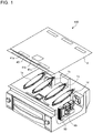
- Fig. 1 is an exploded perspective view showing an induction cooker according to Embodiment 1.
- Fig. 2 is a plan view schematically showing a plurality of heating coils of the induction cooker according to Embodiment 1.
- the induction cooker 100 has at the top thereof a top plate 4 on which a heating target such as a pot is placed.
- the top plate 4 is made entirely of an infrared-transparent material such as heat-resistant tempered glass or crystallized glass.
- the induction cooker 100 includes a plurality of heating coils aligned in one row on the same plane.
- the plurality of heating coils are disposed below the top plate 4.
- the induction cooker 100 includes a four heating coils, namely a first heating coil 1a, a second heating coil 1 b, a third heating coil 1c, and a fourth heating coil 1d.
- the first to fourth heating coils 1a to 1d are aligned in one row in a transverse direction of the top plate 4.
- the first to fourth heating coils 1a to 1d are each constituted by winding a conducting wire subjected to insulating coating and made of metal.
- the conducting wires may be made of any metal such as copper or aluminum. Further, the first to fourth heating coils 1a to 1d have their conducting wires wound independently of one another.
- the first to fourth heating coils 1a to 1d are formed, for example, in elliptical shapes in plan view.
- the first to fourth heating coils 1a to 1d have the same shape and the same size as one another. Note here that the phrase "the same shape and the same size" is not limited to strictly the same shape and the same size but encompasses errors caused by manufacturing errors or other errors and allows for substantially the same shape and substantially the same size.
- the shapes of the first to fourth heating coils 1a to 1d are not limited to elliptical shapes.
- the shapes of the first to fourth heating coils 1a to 1d may for example be quadrangular shapes or other shapes.
- first heating coil 1a the second heating coil 1b, the third heating coil 1c, and the fourth heating coil 1d are sometimes collectively referred to as "each heating coil”.
- an operation unit 40 is provided as an input device for configuring the settings for input power and a cooking menu or other settings in heating a heating target with the first to fourth heating coils 1a to 1d.
- the cooking menu includes, for example, a water boiler mode, a fryer mode, a convector mode, or other modes.
- the convector mode is a cooking menu of causing convection in a liquid cooking target contained in a heating target in cooking such as stewing or noddle boiling. Details will be described later.
- a display unit 41 configured to display, for example, an operating status of each heating coil and the contents of an input and an operation from the operation unit 40 is provided as a notification unit.
- the display unit 41 is divided into a display unit 41a, a display unit 41b, and a display unit 41c for each separate induction heating unit.
- the operation unit 40 is constituted, for example, by a mechanical switch such as a push switch and a tactile switch, a touch switch that senses an input operation through a change in electrostatic capacitance of an electrode, or other switches.
- the display unit 41 is constituted, for example, by an LCD, an LED, or other devices.
- the operation unit 40 and the display unit 41 may be integrated to constitute an operation display unit 43.
- the operation display unit 43 is constituted, for example, by a touch panel including an LCD and a touch switch disposed on an upper surface of the LCD.
- LCD is an abbreviation for liquid crystal device. Further, LED is an abbreviation for light-emitting diode.
- a driver circuit 50 configured to supply high-frequency power to the first to fourth heating coils 1a to 1d is provided. Further, inside the induction cooker 100, a control unit 45 for controlling operation of the induction cooker 100 as a whole including the driver circuit 50 is provided.
- the supply of high-frequency power to the first to fourth heating coils 1a to 1d by the driver circuit 50 causes high-frequency magnetic fields to be generated from the first to fourth heating coils 1a to 1d.
- the driver circuit 50 is provided for each heating coil.
- the driver circuit 50 may be the same in circuit configuration or may vary in circuit configuration from one heating coil to another. A configuration of the driver circuit 50 will be described in detail later.
- Fig. 3 is a plan view explaining alignment of the plurality of heating coils of the induction cooker according to Embodiment 1.
- the elliptical shapes of the first to fourth heating coils 1a to 1d have their minor axes aligned in a straight line CL. That is, the first to fourth heating coils 1a to 1d are aligned in one row so that major axes LA of the elliptical shapes are orthogonal to the straight line CL. Further, the first to fourth heating coils 1a to 1d are aligned so that a spacing L2 between adjacent two of the first to fourth heating coils 1a to 1d is shorter than a half of a length L1 of the minor axis of each of the first to fourth heating coils 1a to 1d.
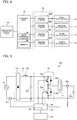
- Fig. 4 is a block diagram showing a configuration of the induction cooker according to Embodiment 1.
- the driver circuit 50 includes a driver circuit 50a, a driver circuit 50b, a driver circuit 50c, and a driver circuit 50d.
- the driver circuit 50a controls driving of the first heating coil 1a.
- the driver circuit 50b controls driving of the second heating coil 1b.
- the driver circuit 50c controls driving of the third heating coil 1c.
- the driver circuit 50d controls driving of the fourth heating coil 1d.
- the supply of a high-frequency current from the driver circuit 50a to the first heating coil 1a causes a high-frequency magnetic field to be generated from the first heating coil 1a.
- the supply of a high-frequency current from the driver circuit 50b to the second heating coil 1b causes a high-frequency magnetic field to be generated from the second heating coil 1b.
- the supply of a high-frequency current from the driver circuit 50c to the third heating coil 1c causes a high-frequency magnetic field to be generated from the third heating coil 1c.
- the supply of a high-frequency current from the driver circuit 50d to the fourth heating coil 1d causes a high-frequency magnetic field to be generated from the fourth heating coil 1d.
- the control unit 45 is constituted by dedicated hardware or a CPU that executes a program stored in a memory 48. Further, the control unit 45 includes a load determination unit 46 configured to determine whether a heating target is placed above each of the first to fourth heating coils 1a to 1d.
- CPU central processing unit
- processing unit processing unit
- arithmetic unit central processing unit
- control unit 45 In a case where the control unit 45 is dedicated hardware, the control unit 45 corresponds, for example, to a single circuit, a composite circuit, an ASIC, an FPGA, or a combination thereof. Each functional unit that is implemented by the control unit 45 may be implemented by individual hardware, or each functional unit may be implemented by one piece of hardware.
- ASIC is an abbreviation for application-specific integrated circuit.
- FPGA is an abbreviation for field-programmable gate array.
- each function that is executed by the control unit 45 is implemented by software, firmware, or a combination thereof.
- the software and the firmware are described as programs and stored in the memory 48.
- the CPU implements each function of the control unit 45 by reading out and executing a program stored in the memory 48.
- an example of the memory 48 is a nonvolatile or volatile semiconductor memory such as a RAM, a ROM, a flash memory, an EPROM, or an EEPROM.
- control unit 45 may be implemented by dedicated hardware, and others may be implemented by software or firmware.
- RAM is an abbreviation for random-access memory.
- ROM is an abbreviation for read-only memory.
- EPROM is an abbreviation for erasable programmable read-only memory.
- EEPROM is an abbreviation for electrically erasable programmable read-only memory.
- Fig. 5 is a diagram showing a driver circuit of the induction cooker according to Embodiment 1.
- the driver circuits 50a to 50d may be the same in circuit configuration, or may vary in circuit configuration from one heating coil to another.
- Fig. 5 illustrates the driver circuit 50a, which drives the first heating coil 1a.
- the driver circuit 50a includes a DC power supply circuit 22, an inverter circuit 23, and a resonant capacitor 24a.
- the DC power supply circuit 22 includes a diode bridge 22a, a reactor 22b, and a smoothing capacitor 22c.
- the DC power supply circuit 22 converts an AC voltage inputted from an AC power supply 21 into a DC voltage and outputs the DC voltage to the inverter circuit 23.
- the DC power source circuit 22 may be shared by the driver circuits 50a to 50d.
- the inverter circuit 23 includes an IGBT 23a and an IGBT 23b, connected in series to an output of the DC power supply circuit 22, that serve as switching elements.
- the inverter circuit 23 includes a diode 23c and a diode 23d, connected in parallel to the IGBT 23a and the IGBT 23b, respectively, that serve as flywheel diodes.
- the inverter circuit 23 is a so-called half-bridge inverter.
- the IGBT 23a and the IGBT 23b are subjected to on-off driving by a driving signal outputted from the control unit 45.
- the control unit 45 outputs an alternately on-off driving signal by bringing the IGBT 23b into an off state while the IGBT 23a is turned on and bringing the IGBT 23b into an on state while the IGBT 23a is turned off.
- This causes the inverter circuit 23 to convert DC power outputted from the DC power supply circuit 22 into AC power of a high frequency of 20 to 100 kHz and supply the power to a resonant circuit composed of the first heating coil 1a and the resonant capacitor 24a.
- the resonant capacitor 24a is connected in series to the first heating coil 1a.
- the resonant circuit composed of the first heating coil 1a and the resonant capacitor 24a has a resonant frequency that depends on the inductance of the first heating coil 1a and the capacitance of the resonant capacitor 24a.
- the inductance of the first heating coil 1a changes according to the characteristics of a metal load, when the heating target, which is the metal load, is subjected to magnetic coupling, and the resonant frequency of the resonant circuit changes according to this change in inductance.
- a heating target placed on the top plate 4 directly above the first heating coil 1a is inductively heated by a high-frequency magnetic flux produced by the high-frequency current flowing through the first heating coil 1a.
- the IGBT 23a and the IGBT 23b which serve as switching elements, are each constituted, for example, by a silicon semiconductor but may alternatively be each constituted by a wide bandgap semiconductor such as silicon carbide or gallium nitride.
- the driver circuit 50 can have a small-sized heat-dissipating fin, as the driver circuit 50a is satisfactory in heat dissipation. This makes it possible to achieve reductions in size and cost of the driver circuit 50a.
- the driver circuit 50a includes an input current detection unit 25a and a coil current detection unit 25b.
- the input current detection unit 25a is constituted, for example, by a current sensor, detects an electric current inputted from the AC power supply 21 to the DC power supply circuit 22, and outputs a voltage signal equivalent to an input current value to the control unit 45.
- the coil current detection unit 25b is constituted, for example, by a current sensor, detects an electric current flowing through the first heating coil 1a, and outputs a voltage signal equivalent to a coil current value to the control unit 45.
- the load determination unit 46 of the control unit 45 performs a load determination process.
- the load determination unit 46 determines, for example on the basis of a relationship between a coil current of each of the first to fourth heating coils 1a to 1d and an input current, whether a heating target is placed above each heating coil. Specifically, the load determination unit 46 drives the inverter circuit 23 of each of the driver circuits 50a to 50d with a particular driving signal for use in load determination. The control unit 45 detects an input current from an output signal of the input current detection unit 25a. Further, at the same time, the control unit 45 detects a coil current from an output signal of the coil current detection unit 25b. The load determination unit 46 determines, from the input current thus detected, the coil current thus detected, and a load determination table stored in advance in the memory 48, whether a heating target is placed above each heating coil.
- the load determination unit 46 needs only be configured to determine whether a heating target is placed above each heating coil. For example, the load determination unit 46 may determine the presence or absence of a heating target by an optical method. Specifically, the load determination unit 46 may determine the presence or absence of a heating target by projecting light upward from below the top plate 4 and detecting reflected light from the heating target.
- control unit 45 controls the driver circuits 50a to 50d according to a result of the load determination process and performs a heating operation of supplying high-frequency power appropriate to induction heating power and the cooking menu.
- the following describes, in relation to an operation that is performed in a case where the convector mode has been selected as a cooking menu by an input from the operation unit 40, a case where the size of a heating target placed on the top plate 4 is a small diameter, a case where the size of a heating target placed on the top plate 4 is a medium diameter, and a case where the size of a heating target placed on the top plate 4 is a large diameter.
- the size of a heating target 5a that is placed over two of the first to fourth heating coils 1a to 1d is referred to as "small diameter”.
- the size of a heating target 5b that is placed over three of the first to fourth heating coils 1a to 1d is referred to as “medium diameter”.
- the size of a heating target 5c that is placed over four of the first to fourth heating coils 1a to 1d is referred to as "large diameter”.
- heating target 5a, the heating target 5b, and the heating target 5c they are referred to as "heating target 5".
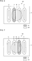
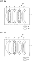
- Figs. 6 and 7 are each a plan view schematically showing a conducting state of the plurality of heating coils of the induction cooker according to Embodiment 1.
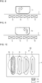
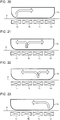
- Figs. 8 and 9 are each a diagram showing the plurality of heating coils of the induction cooker according to Embodiment 1 and a heating target.
- the solid lines indicate the first to fourth heating coils 1a to 1d disposed below the top plate 4, and the dotted line indicates the heating target 5a placed on the top plate 4.
- Figs. 8 and 9 each schematically show a longitudinal section with the heating target 5a placed on the top plate 4. Further, in Figs. 8 and 9 , the arrows indicate directions of convection having occurred in a liquid cooking target contained in the heating target 5a.
- the control unit 45 alternately switches between the supply of electric power to the second heating coil 1b and the supply of electric power to the third heating coil 1c over time.
- control unit 45 supplies electric power to one of the two heating coils and sequentially changes, over time, the heating coils to which the power is supplied.
- control unit 45 equalizes an amount of electric power represented by the product of electric power that is supplied to the second heating coil 1b and the duration of conduction and an amount of electric power represented by the product of electric power that is supplied to the third heating coil 1c and the duration of conduction. That is, the control unit 45 equalizes the products of electric power that is supplied to adjacent two of the first to fourth heating coils 1a to 1d and the duration of conduction.
- the phrase "the same amount of electric power” is not limited to strictly the same value but encompasses errors caused by control errors or other errors and allows for substantially the same amount of electric power. The same applies to the following description.
- the alternate conduction of electricity through the two adjacent heating coils effects convection in the liquid cooking target, such as broth, contained in the heating target 5a, allowing the liquid cooking target to disperse.
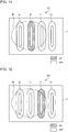
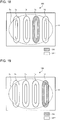
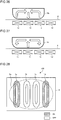
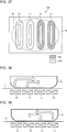
- Figs. 10 to 12 are each a plan view schematically showing a conducting state of the plurality of heating coils of the induction cooker according to Embodiment 1.
- Figs. 13 to 15 are each a diagram showing the plurality of heating coils of the induction cooker according to Embodiment 1 and a heating target.
- the solid lines indicate the first to fourth heating coils 1a to 1d disposed below the top plate 4, and the dotted line indicates the heating target 5b placed on the top plate 4.
- Figs. 13 to 15 each schematically show a longitudinal section with the heating target 5b placed on the top plate 4. Further, in Figs. 13 to 15 , the arrows indicate directions of convection having occurred in a liquid cooking target contained in the heating target 5b.
- the control unit 45 When, as shown in Figs. 10 to 12 , the heating target 5b is placed over the first heating coil 1a, the second heating coil 1b, and the third heating coil 1c, the control unit 45 performs the following operation.
- the control unit 45 sequentially switches among the supply of electric power to the first heating coil 1a, the supply of electric power to the second heating coil 1b, and the supply of electric power to the third heating coil 1c over time.
- control unit 45 supplies electric power to one of the three adjacent heating coils and sequentially changes, over time, the heating coils to which the power is supplied.
- control unit 45 equalizes amounts of electric power that are the products of electric power that is supplied to the first heating coil 1a, the second heating coil 1b, and the third heating coil 1c and the duration of conduction. That is, the control unit 45 equalizes the products of electric power that is supplied to adjacent three of the first to fourth heating coils 1a to 1d and the duration of conduction.
- the sequential switching of the supply of electric power to the three adjacent heating coils effects convection in the liquid cooking target, such as broth, contained in the heating target 5b, allowing the liquid cooking target to disperse.
- the order in which electric power is supplied to the three adjacent heating coils is not limited to the order of the first heating coil 1a, the second heating coil 1b, and the third heating coil 1c, but may be any order.
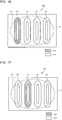
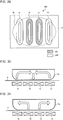
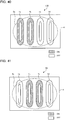
- Figs. 16 to 19 are each a plan view schematically showing a conducting state of the plurality of heating coils of the induction cooker according to Embodiment 1.
- Figs. 20 to 23 are each a diagram showing the plurality of heating coils of the induction cooker according to Embodiment 1 and a heating target.
- the solid lines indicate the first to fourth heating coils 1a to 1d disposed below the top plate 4, and the dotted line indicates the heating target 5c placed on the top plate 4.
- Figs. 20 to 23 each schematically show a longitudinal section with the heating target 5c placed on the top plate 4. Further, in Figs. 20 to 23 , the arrows indicate directions of convection having occurred in a liquid cooking target contained in the heating target 5c.
- the control unit 45 When, as shown in Figs. 16 to 19 , the heating target 5c is placed over the first heating coil 1a, the second heating coil 1b, the third heating coil 1c, and the fourth heating coil 1d, the control unit 45 performs the following operation.
- the control unit 45 sequentially switches among the supply of electric power to the first heating coil 1a, the supply of electric power to the second heating coil 1b, the supply of electric power to the third heating coil 1c, and the supply of electric power to the fourth heating coil 1d over time.
- control unit 45 supplies electric power to one of the four heating coils and sequentially changes, over time, the heating coils to which the power is supplied.
- control unit 45 equalizes amounts of electric power that are the products of electric power that is supplied to the first heating coil 1a, the second heating coil 1b, the third heating coil 1c, and the fourth heating coil 1d and the duration of conduction. That is, the control unit 45 equalizes the products of electric power that is supplied to the first to fourth heating coils 1a to 1d and the duration of conduction.
- the sequential switching of the supply of electric power to the four adjacent heating coils effects convection in the liquid cooking target, such as broth, contained in the heating target 5c, allowing the liquid cooking target to disperse.
- the order in which electric power is supplied to the four adjacent heating coils is not limited to the order of the first heating coil 1a, the second heating coil 1b, the third heating coil 1c, and the fourth heating coil 1d, but may be any order.
- control unit 45 may supply more electric power to at least one, but not all, of the two or more adjacent heating coils than to one or more, but not all, other ones of the two or more adjacent heating coils and change, over time, the heating coils to which the more power is supplied.
- the control unit 45 supplies electric power to at least one of the adjacent two or more heating coils and changes, over time, the heating coils to which the power is supplied.
- cooking with heat is performed by those ones of the first to fourth heating coils 1a to 1d over which the heating target 5 is placed. This makes it possible to handle heating targets 5 whose sizes vary from small to large in diameter and brings about improvement in user-friendliness.
- Embodiment 1 electric power is supplied to one of the two or more heating coils over which the heating target 5 is placed, and the heating coils to which the power is supplied are sequentially changed over time.
- control unit 45 equalizes the products of electric power that is supplied to adjacent two or more of the first to fourth heating coils 1a to 1d and the duration of conduction.
- the first to fourth heating coils 1a to 1d have the same shape and the same size as one another.
- each heating coil to have the same area in plan view and makes it possible to reduce nonuniformity in heating temperature of the heating target 5.
- the first to fourth heating coils 1a to 1d are aligned so that the spacing L2 between adjacent two of the first to fourth heating coils 1a to 1d is shorter than a half of the length L1 of the minor axis of each of the first to fourth heating coils 1a to 1d.
- the aforementioned heating operation may also be applied to a cooking mode of heating a heating target 5, such as a frying pan or an iron plate, on which a solid cooking target is placed.
- the solid cooking target placed on the heating target 5 can be heated or kept warm with reduced scorching.
- control unit 45 equalizes the products of electric power that is supplied to adjacent three or more of the first to fourth heating coils 1a to 1d and the duration of conduction.
- An outer peripheral part of the heating target 5 is larger in heat transfer amount than a central part of the heating target 5. For this reason, the outer peripheral part of the heating target 5 may be more likely to become lower in temperature than the central part of the heating target 5. For this reason, the following operation may be performed instead of the foregoing operation.
- control unit 45 When the heating target 5 is placed over adjacent three or more of the first to fourth heating coils 1a to 1d, the control unit 45 performs the following operation.
- the control unit 45 makes the product of electric power that is supplied to outside two or more of the three or more adjacent heating coils and the duration of conduction larger than the product of electric power that is supplied to inside one or more of the three or more adjacent heating coils and the duration of conduction, the inside being the direction to center of the plane on which the coils are aligned.
- the control unit 45 performs the following operation.
- the control unit 45 makes an amount of electric power represented by the product of electric power that is supplied to the first heating coil 1a and the third heating coil 1c and the duration of conduction larger than an amount of electric power represented by the product of electric power that is supplied to the second heating coil 1b and the duration of conduction.
- control unit 45 when the large-diameter heating target 5c is placed over the first heating coil 1a, the second heating coil 1b, the third heating coil 1c, and the fourth heating coil 1d, the control unit 45 performs the following operation.
- the control unit 45 makes an amount of electric power represented by the product of electric power that is supplied to the first heating coil 1a and the fourth heating coil 1d and the duration of conduction larger than an amount of electric power represented by the product of electric power that is supplied to the second heating coil 1b and the third heating coil 1c and the duration of conduction.
- This operation can make the outer peripheral part of the heating target 5 larger in heat transfer amount than the central part of the heating target 5 and makes it possible to reduce nonuniformity in heating temperature of the heating target 5. This makes it possible to reduce nonuniformity in temperature of the cooking target and scorching of the cooking target.
- Embodiment 2 The following describes operation of an induction cooker 100 according to Embodiment 2 with a focus on differences from Embodiment 1.
- the induction cooker 100 according to Embodiment 2 is the same in configuration as that of Embodiment 1.
- Components that are the same as those of Embodiment 1 are given the same reference signs, and a description of such components is omitted.
- the load determination unit 46 of the control unit 45 performs a load determination process.
- the control unit 45 controls the driver circuits 50a to 50d according to a result of the load determination process and performs a heating operation appropriate to induction heating power and the cooking menu.
- the following describes, in relation to an operation that is performed in a case where the convector mode has been selected as a cooking menu by an input from the operation unit 40, a case where the size of a heating target placed on the top plate 4 is a medium diameter and a case where the size of a heating target placed on the top plate 4 is a large diameter.
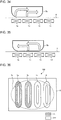
- Figs. 24 and 25 are each a plan view schematically showing a conducting state of the plurality of heating coils of the induction cooker according to Embodiment 2.
- Figs. 26 and 27 are each a diagram showing the plurality of heating coils of the induction cooker according to Embodiment 2 and a heating target.
- the solid lines indicate the first to fourth heating coils 1a to 1d disposed below the top plate 4, and the dotted line indicates the heating target 5b placed on the top plate 4.
- Figs. 26 and 27 each schematically show a longitudinal section with the heating target 5b placed on the top plate 4. Further, in Figs. 26 and 27 , the arrows indicate directions of convection having occurred in a liquid cooking target contained in the heating target 5b.
- the control unit 45 When, as shown in Figs. 24 and 25 , the heating target 5b is placed over the first heating coil 1a, the second heating coil 1b, and the third heating coil 1c, the control unit 45 performs the following operation.
- the control unit 45 alternately switches between the supply of electric power to the first heating coil 1a and the third heating coil 1c and the supply of electric power to the second heating coil 1b.
- control unit 45 alternately switches between the supply of electric power to inside one of the three heating coils and the supply of electric power to outside two of the three heating coils.
- control unit 45 equalizes an amount of electric power represented by the product of a total of electric power that is supplied to the first heating coil 1a and the third heating coil 1c and the duration of conduction and an amount of electric power represented by the product of electric power that is supplied to the second heating coil 1b and the duration of conduction.
- the liquid cooking target contained in the heating target 5b convects in such a manner that a portion of the liquid cooking target located above the third heating coil 1c is heated, moves upward from the lower part of the heating target 5b, and then moves toward the left as see from the front of the drawing sheet of Fig. 26 , that is, toward an area above the second heating coil 1b.
- the liquid cooking target contained in the heating target 5b convects in such a manner as to move downward in a central part of the heating target 5b.
- the alternate switching between the supply of electric power to inside one of the three adjacent heating coils and the supply of electric power to outside two of the three adjacent heating coils effects convection in the liquid cooking target, such as broth, contained in the heating target 5b, allowing the liquid cooking target to disperse.
- Figs. 28 and 29 are each a plan view schematically showing a conducting state of the plurality of heating coils of the induction cooker according to Embodiment 2.
- Figs. 30 and 31 are each a diagram showing the plurality of heating coils of the induction cooker according to Embodiment 2 and a heating target.
- the solid lines indicate the first to fourth heating coils 1a to 1d disposed below the top plate 4, and the dotted line indicates the heating target 5c placed on the top plate 4.
- Figs. 30 and 31 each schematically show a longitudinal section with the heating target 5c placed on the top plate 4. Further, in Figs. 30 and 31 , the arrows indicate directions of convection having occurred in a liquid cooking target contained in the heating target 5c.
- the control unit 45 When, as shown in Figs. 28 and 29 , the heating target 5c is placed over the first heating coil 1a, the second heating coil 1b, the third heating coil 1c, and the fourth heating coil 1d, the control unit 45 performs the following operation.
- the control unit 45 alternately switches between the supply of electric power to the first heating coil 1a and the fourth heating coil 1d and the supply of electric power to the second heating coil 1b and the third heating coil 1c.
- control unit 45 alternately switches between the supply of electric power to inside two of the four adjacent heating coils and the supply of electric power to outside two of the four adjacent heating coils.
- control unit 45 equalizes an amount of electric power represented by the product of a total of electric power that is supplied to the first heating coil 1a and the fourth heating coil 1d and the duration of conduction and an amount of electric power represented by the product of a total of electric power that is supplied to the second heating coil 1b and the third heating coil 1c and the duration of conduction.
- the liquid cooking target contained in the heating target 5c convects in such a manner that a portion of the liquid cooking target located above the fourth heating coil 1d is heated, moves upward from the lower part of the heating target 5c, and then moves toward the left as see from the front of the drawing sheet of Fig. 30 , that is, toward an area above the third heating coil 1c.
- the liquid cooking target contained in the heating target 5c convects in such a manner as to move downward in a central part of the heating target 5c.
- the liquid cooking target contained in the heating target 5c convects in such a manner that a portion of the liquid cooking target located above the third heating coil 1c is heated, moves upward from the lower part of the heating target 5c, and then moves toward the right as see from the front of the drawing sheet of Fig. 31 , that is, toward an area above the fourth heating coil 1d.
- the alternate switching between the supply of electric power to inside two of the four adjacent heating coils and the supply of electric power to outside two of the four adjacent heating coils effects convection in the liquid cooking target, such as broth, contained in the heating target 5b, allowing the liquid cooking target to disperse.
- control unit 45 may supply more electric power to at least one of the three or more adjacent heating coils than to one or more other ones of the three or more adjacent heating coils.
- the control unit 45 when the heating target 5 is placed over adjacent three or more of the first to fourth heating coils 1a to 1d, the control unit 45 alternately switches between the supply of electric power to inside one or more of the three or more adjacent heating coils and the supply of electric power to outside two or more of the three or more adjacent heating coils.
- control unit 45 equalizes the products of electric power that is supplied to adjacent three or more of the first to fourth heating coils 1a to 1d and the duration of conduction. This makes it possible to reduce nonuniformity in heating temperature of the heating target 5 and reduce nonuniformity in temperature of the cooking target.
- the aforementioned heating operation may also be applied to a cooking mode of heating a heating target 5, such as a frying pan or an iron plate, on which a solid cooking target is placed.
- the solid cooking target placed on the heating target 5 can be heated or kept warm with reduced scorching.
- a heating operation of the induction cooker 100 according to Embodiment 2 and a heating operation of the induction cooker 100 according to Embodiment 1 may be combined with each other.
- the control unit 45 may alternately perform a heating operation of the induction cooker 100 according to Embodiment 2 and a heating operation of the induction cooker 100 according to Embodiment 1.
- control unit 45 equalizes the products of electric power that is supplied to adjacent three or more of the first to fourth heating coils 1a to 1d and the duration of conduction.
- the outer peripheral part of the heating target 5 is larger in heat transfer amount than the central part of the heating target 5. For this reason, the outer peripheral part of the heating target 5 may be more likely to become lower in temperature than the central part of the heating target 5. For this reason, the following operation may be performed instead of the foregoing operation.
- control unit 45 When the heating target 5 is placed over adjacent three or more of the first to fourth heating coils 1a to 1d, the control unit 45 performs the following operation.
- the control unit 45 makes the product of electric power that is supplied to outside two of the three or more adjacent heating coils and the duration of conduction larger than the product of electric power that is supplied to inside one or more of the three or more adjacent heating coils and the duration of conduction.
- control unit 45 when the medium-diameter heating target 5b is placed over the first heating coil 1a, the second heating coil 1b, and the third heating coil 1c, the control unit 45 performs the following operation.
- the control unit 45 makes an amount of electric power represented by the product of a total of electric power that is supplied to the first heating coil 1a and the third heating coil 1c and the duration of conduction larger than an amount of electric power represented by the product of electric power that is supplied to the second heating coil 1b and the duration of conduction.
- control unit 45 when the large-diameter heating target 5c is placed over the first heating coil 1a, the second heating coil 1b, the third heating coil 1c, and the fourth heating coil 1d, the control unit 45 performs the following operation.
- the control unit 45 makes an amount of electric power represented by the product of a total of electric power that is supplied to the first heating coil 1a and the fourth heating coil 1d and the duration of conduction larger than an amount of electric power represented by the product of a total of electric power that is supplied to the second heating coil 1b and the third heating coil 1c and the duration of conduction.
- This operation can make the outer peripheral part of the heating target 5 larger in heat transfer amount than the central part of the heating target 5 and makes it possible to reduce nonuniformity in heating temperature of the heating target 5. This makes it possible to reduce nonuniformity in temperature of the cooking target and scorching of the cooking target.
- Embodiment 3 The following describes operation of an induction cooker 100 according to Embodiment 3 with a focus on differences from Embodiments 1 and 2.
- the induction cooker 100 according to Embodiment 3 is the same in configuration as that of Embodiment 1.
- Components that are the same as those of Embodiment 1 are given the same reference signs, and a description of such components is omitted.
- the load determination unit 46 of the control unit 45 performs a load determination process.
- the control unit 45 controls the driver circuits 50a to 50d according to a result of the load determination process and performs a heating operation appropriate to induction heating power and the cooking menu.
- the following describes, in relation to an operation that is performed in a case where the convector mode has been selected as a cooking menu by an input from the operation unit 40, a case where the size of a heating target placed on the top plate 4 is a medium diameter and a case where the size of a heating target placed on the top plate 4 is a large diameter.
- Figs. 32 and 33 are each a plan view schematically showing a conducting state of the plurality of heating coils of the induction cooker according to Embodiment 3.
- Figs. 34 and 35 are each a diagram showing the plurality of heating coils of the induction cooker according to Embodiment 3 and a heating target.
- the solid lines indicate the first to fourth heating coils 1a to 1d disposed below the top plate 4, and the dotted line indicates the heating target 5b placed on the top plate 4.
- Figs. 34 and 35 each schematically show a longitudinal section with the heating target 5b placed on the top plate 4. Further, in Figs. 34 and 35 , the arrows indicate directions of convection having occurred in a liquid cooking target contained in the heating target 5b.
- the control unit 45 When, as shown in Figs. 32 and 33 , the heating target 5b is placed over the first heating coil 1a, the second heating coil 1b, and the third heating coil 1c, the control unit 45 performs the following operation.
- the control unit 45 alternately switches between the supply of electric power to a set of the first heating coil 1a and the second heating coil 1b and the supply of electric power to a set of the second heating coil 1b and the third heating coil 1c.
- control unit 45 supplies electric power to a set of adjacent two of the three adjacent ones of the first to fourth heating coils 1a to 1d and changes the set of the two of the three adjacent ones of the first to fourth heating coils 1a to 1d over time.
- control unit 45 equalizes an amount of electric power represented by the product of a total of electric power that is supplied to the first heating coil 1a and the second heating coil 1b and the duration of conduction and an amount of electric power represented by the product of a total of electric power that is supplied to the second heating coil 1b and the third heating coil 1c and the duration of conduction.
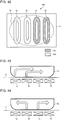
- Figs. 36 and 37 are each a plan view schematically showing a conducting state of the plurality of heating coils of the induction cooker according to Embodiment 3.
- Figs. 38 and 39 are each a diagram showing the plurality of heating coils of the induction cooker according to Embodiment 3 and a heating target.
- the solid lines indicate the first to fourth heating coils 1a to 1d disposed below the top plate 4, and the dotted line indicates the heating target 5c placed on the top plate 4.
- Figs. 38 and 39 each schematically show a longitudinal section with the heating target 5c placed on the top plate 4. Further, in Figs. 38 and 39 , the arrows indicate directions of convection having occurred in a liquid cooking target contained in the heating target 5c.
- the control unit 45 When, as shown in Figs. 36 and 37 , the heating target 5c is placed over the first heating coil 1a, the second heating coil 1b, the third heating coil 1c, and the fourth heating coil 1d, the control unit 45 performs the following operation.
- the control unit 45 alternately switches between the supply of electric power to a set of the first heating coil 1a and the second heating coil 1b and the supply of electric power to a set of the third heating coil 1c and the fourth heating coil 1d.
- control unit 45 supplies electric power to a set of adjacent two of the four adjacent heating coils and changes the set of the two of the four adjacent heating coils over time.
- control unit 45 equalizes an amount of electric power represented by the product of a total of electric power that is supplied to the first heating coil 1a and the second heating coil 1b and the duration of conduction and an amount of electric power represented by the product of a total of electric power that is supplied to the third heating coil 1c and the fourth heating coil 1d and the duration of conduction.
- control unit 45 may supply more electric power to at least one of the three or more adjacent heating coils than to one or more other ones of the three or more adjacent heating coils.
- control unit 45 is configured to, when the heating target 5 is placed over adjacent three or more of the first to fourth heating coils 1a to 1d, supply electric power to a set of adjacent two of the three or more adjacent ones of the first to fourth heating coils 1a to 1d and change the set of the two of the three or more adjacent ones of the first to fourth heating coils 1a to 1d over time.
- the supply of electric power to two adjacent heating coils allows the liquid cooking target contained in the heating target 5 to convect in a larger way than the supply of electric power to one heating coil or two non-adjacent heating coils.
- control unit 45 equalizes the products of electric power that is supplied to adjacent two of the first to fourth heating coils 1a to 1d and the duration of conduction. This makes it possible to reduce nonuniformity in heating temperature of the heating target 5 and reduce nonuniformity in temperature of the cooking target.
- the aforementioned heating operation may also be applied to a cooking mode of heating a heating target 5, such as a frying pan or an iron plate, on which a solid cooking target is placed.
- the solid cooking target placed on the heating target 5 can be heated or kept warm with reduced scorching.
- a heating operation of the induction cooker 100 according to Embodiment 3 and heating operations of the induction cookers 100 according to Embodiments 1 and 2 may be combined with one another.
- the control unit 45 may sequentially perform heating operations of the induction cookers 100 according to Embodiments 1 to 3.
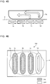
- Figs. 40 to 42 are each a plan view schematically showing a conducting state of the plurality of heating coils of the induction cooker according to Embodiment 3.
- Figs. 43 to 45 are each a diagram showing the plurality of heating coils of the induction cooker according to Embodiment 3 and a heating target.
- the solid lines indicate the first to fourth heating coils 1a to 1d disposed below the top plate 4, and the dotted line indicates the heating target 5c placed on the top plate 4.
- Figs. 43 to 45 each schematically show a longitudinal section with the heating target 5c placed on the top plate 4. Further, in Figs. 43 to 45 , the arrows indicate directions of convection having occurred in a liquid cooking target contained in the heating target 5c.
- the control unit 45 When, as shown in Figs. 40 to 42 , the heating target 5c is placed over the first heating coil 1a, the second heating coil 1b, the third heating coil 1c, and the fourth heating coil 1d, the control unit 45 performs the following operation.
- the control unit 45 sequentially switches among the supply of electric power to a set of the first heating coil 1a and the second heating coil 1b, the supply of electric power to a set of the second heating coil 1b and the third heating coil 1c, and the supply of electric power to a set of the third heating coil 1c and the fourth heating coil 1d.
- control unit 45 supplies electric power to a set of adjacent two of the four adjacent heating coils and changes the set of the two of the four adjacent heating coils over time.
- control unit 45 equalizes an amount of electric power represented by the product of a total of electric power that is supplied to the first heating coil 1a and the second heating coil 1b and the duration of conduction, an amount of electric power represented by the product of a total of electric power that is supplied to the second heating coil 1b and the third heating coil 1c and the duration of conduction, and an amount of electric power represented by the product of a total of electric power that is supplied to the third heating coil 1c and the fourth heating coil 1d and the duration of conduction.
- the liquid cooking target contained in the heating target 5c convects in such a manner that a portion of the liquid cooking target located above the third heating coil 1c is heated, moves upward from the lower part of the heating target 5c, and then moves toward the right as see from the front of the drawing sheet of Fig. 44 , that is, toward an area above the fourth heating coil 1d.
- this operation more disperses heating positions of the heating target 5 over time than the operation of alternately switching between two sets, so that the liquid cooking target contained in the heating target 5 can be warmed or kept warm with reduced scorching.
- Electric power may be supplied to a set of adjacent three of the first to fourth heating coils 1a to 1d, and the supply of electric power to the set of three heating coils may be sequentially changed over time.
- a specific example is described below.
- Figs. 46 and 47 are each a plan view schematically showing a conducting state of the plurality of heating coils of the induction cooker according to Embodiment 3.
- Figs. 48 and 49 are each a diagram showing the plurality of heating coils of the induction cooker according to Embodiment 3 and a heating target.
- the solid lines indicate the first to fourth heating coils 1a to 1d disposed below the top plate 4, and the dotted line indicates the heating target 5c placed on the top plate 4.
- Figs. 48 and 49 each schematically show a longitudinal section with the heating target 5c placed on the top plate 4. Further, in Figs. 48 and 49 , the arrows indicate directions of convection having occurred in a liquid cooking target contained in the heating target 5c.
- the control unit 45 When, as shown in Figs. 46 and 47 , the heating target 5c is placed over the first heating coil 1a, the second heating coil 1b, the third heating coil 1c, and the fourth heating coil 1d, the control unit 45 performs the following operation.
- the control unit 45 sequentially switches between the supply of electric power to a set of the first heating coil 1a, the second heating coil 1b, and the third heating coil 1c and the supply of electric power to a set of the second heating coil 1b, the third heating coil 1c, and the fourth heating coil 1d.
- control unit 45 supplies electric power to a set of adjacent three of the four adjacent heating coils and changes the set of the three of the four adjacent heating coils over time.
- control unit 45 equalizes an amount of electric power represented by the product of a total of electric power that is supplied to the first heating coil 1a, the second heating coil 1b, and the third heating coil 1c and the duration of conduction and an amount of electric power represented by the product of a total of electric power that is supplied to the second heating coil 1b, the third heating coil 1c, and the fourth heating coil 1d and the duration of conduction.
- control unit 45 equalizes the products of electric power that is supplied to adjacent three or more of the first to fourth heating coils 1a to 1d and the duration of conduction.
- An outer peripheral part of the heating target 5 is larger in heat transfer amount than a central part of the heating target 5. For this reason, the outer peripheral part of the heating target 5 may be more likely to become lower in temperature than the central part of the heating target 5. For this reason, the following operation may be performed instead of the foregoing operation.
- control unit 45 When the heating target 5 is placed over adjacent three or more of the first to fourth heating coils 1a to 1d, the control unit 45 performs the following operation.
- the control unit 45 makes the product of electric power that is supplied to outside two of the three or more adjacent heating coils and the duration of conduction larger than the product of electric power that is supplied to inside one or more of the three or more adjacent heating coils and the duration of conduction.
- control unit 45 when the medium-diameter heating target 5b is placed over the first heating coil 1a, the second heating coil 1b and the third heating coil 1c, the control unit 45 performs the following operation.
- the control unit 45 makes an amount of electric power represented by the product of a total of electric power that is supplied to the first heating coil 1a and the third heating coil 1c and the duration of conduction larger than an amount of electric power represented by the product of electric power that is supplied to the second heating coil 1b and the duration of conduction.
- control unit 45 when the large-diameter heating target 5c is placed over the first heating coil 1a, the second heating coil 1b, the third heating coil 1c, and the fourth heating coil 1d, the control unit 45 performs the following operation.
- the control unit 45 makes an amount of electric power represented by the product of a total of electric power that is supplied to the first heating coil 1a and the fourth heating coil 1d and the duration of conduction larger than an amount of electric power represented by the product of a total of electric power that is supplied to the second heating coil 1b and the third heating coil 1c and the duration of conduction.
- This operation can make the outer peripheral part of the heating target 5 larger in heat transfer amount than the central part of the heating target 5 and makes it possible to reduce nonuniformity in heating temperature of the heating target 5. This makes it possible to reduce nonuniformity in temperature of the cooking target and scorching of the cooking target.
- Embodiment 4 describes operation of an induction cooker 100 according to Embodiment 4 with a focus on differences from Embodiments 1 to 3.
- the induction cooker 100 according to Embodiment 4 is the same in configuration as that of Embodiment 1.
- Components that are the same as those of Embodiment 1 are given the same reference signs, and a description of such components is omitted.
- Fig. 50 is a perspective view showing an induction cooker according to Embodiment 4 and a heating target. It should be noted that Fig. 50 omits illustration of a lower configuration of the top plate 4.
- the control unit 45 When, as shown in Fig. 50 , a small-diameter heating target 5a1 is placed over the first heating coil 1a and the second heating coil 1b by a user and a small-diameter heating target 5a2 is placed over the third heating coil 1c and the fourth heating coil 1d by the user, the control unit 45 performs the following operation. As in the case of Embodiment 1, when the operation unit 40 is given an instruction to start heating, the load determination unit 46 of the control unit 45 performs a load determination process. The control unit 45 controls the driver circuits 50a to 50d according to a result of the load determination process and performs a heating operation appropriate to induction heating power and the cooking menu.
- the control unit 45 When a cooking menu in which the two heating targets 5a1 and 5a2 are simultaneously subjected to cooking with heat in the convector mode is selected by an input from the operation unit 40, the control unit 45 simultaneously performs a heating operation of producing convection in a liquid cooking target contained in the heating target 5a1 and a heating operation of producing convection in a liquid cooking target contained in the heating target 5a2. Specifically, the control unit 45 alternately switches between the supply of electric power to the first heating coil 1a and the supply of electric power to the second heating coil 1b over time. At the same time, the control unit 45 alternately switches between the supply of electric power to the third heating coil 1c and the supply of electric power to the fourth heating coil 1d over time.
- the heating target 5a when the heating target 5a is placed over a set of adjacent two of the first to fourth heating coils 1a to 1d and there are two adjacent sets of adjacent two of the first to fourth heating coils 1a to 1d, the supply of electric power to the two adjacent heating coils of each of the two sets is alternately switched.
- the alternate conduction of electricity through the two adjacent heating coils of each of the two sets effects convection in each of the liquid cooking targets, such as broth, contained in the heating targets 5a1 and 5a2, allowing the liquid cooking targets to disperse. Further, this makes it possible to simultaneously heat two heating targets 5a1 and 5a1 in the convector mode and brings about improvement in user-friendliness.
- control unit 45 of the induction cooker 100 performs the following operation.
- the control unit 45 makes the duration of simultaneous supply of electric power to the first heating coil 1a and the fourth heating coil 1d shorter than the duration of simultaneous supply of electric power to the second heating coil 1b and the third heating coil 1c. That is, the control unit 45 makes the duration of simultaneous supply of electric power to outside two of the plurality of heating coils shorter than the duration of simultaneous supply of electric power to inside two of the plurality of heating coils. Specific examples are described with reference to Figs. 51 and 52 .
- Fig. 51 is a diagram explaining a heating operation of the induction cooker according to Embodiment 4.
- the legend "ON” represents a state where electric power is supplied to a heating coil
- the legend "OFF” represents a state where the supply of electric power is stopped.
- the control unit 45 equalizes cycles of switching T1 of electric power that is supplied to each heating coil. Further, in a period of time T1 a, the control unit 45 turns on the first heating coil 1a and the third heating coil 1c and turns off the second heating coil 1b and the fourth heating coil 1d. Further, in a period of time T1 b, the control unit 45 turns off the first heating coil 1a and the third heating coil 1c and turns on the second heating coil 1b and the fourth heating coil 1d.
- the period of time T1 a and the period of time T1 b are equal in length of time.
- This operation zeroes the duration of simultaneous supply of electric power to the first heating coil 1a and the fourth heating coil 1d, which are disposed toward the outside. Further, this operation zeroes the duration of simultaneous supply of electric power to the second heating coil 1b and the third heating coil 1c, which are disposed toward the center.
- Fig. 52 is a diagram explaining a heating operation of the induction cooker according to Embodiment 4.
- the legend "ON” represents a state where electric power is supplied to a heating coil
- the legend "OFF” represents a state where the supply of electric power is stopped.
- the control unit 45 sets, to T1, cycles of switching of electric power that is supplied to the first heating coil 1a and the second heating coil 1b.
- T1 a the control unit 45 turns on the first heating coil 1a and turns off the second heating coil 1b.
- T1 b the control unit 45 turns off the first heating coil 1a and turns on the second heating coil 1b.
- the period of time T1a and the period of time T1b are equal in length of time.
- control unit 45 sets, to T2, cycles of switching of electric power that is supplied to the third heating coil 1c and the fourth heating coil 1d.
- T2 is longer than T1.
- the control unit 45 turns off the third heating coil 1c and turns on the fourth heating coil 1d.
- the control unit 45 turns on the third heating coil 1c and turns off the fourth heating coil 1d.
- the period of time T2a and the period of time T2b are equal in length of time.
- This operation makes the duration Tout of simultaneous supply of electric power to the first heating coil 1a and the fourth heating coil 1d, which are disposed toward the outside, shorter than the duration Tin of simultaneous supply of electric power to the second heating coil 1b and the third heating coil 1c, which are disposed toward the center.
- Embodiment 4 has described a case where the two heating targets 5a1 and 5a2 are placed over four heating coils, namely the first to fourth heating coils 1a to 1d, this is not intended to impose any limitation on the number of heating coils or the number of heating targets 5a.
- heating coils may be aligned in one row, and three heating targets 5a may be placed and each heated in the convector mode by two heating coils.
- Embodiment 5 The following describes operation of an induction cooker 100 according to Embodiment 5 with a focus on differences from Embodiments 1 to 4.
- the induction cooker 100 according to Embodiment 5 is the same in configuration as that of Embodiment 1.
- Components that are the same as those of Embodiment 1 are given the same reference signs, and a description of such components is omitted.
- control unit 45 of the induction cooker 100 according to Embodiment 5 performs the following operation.
- control unit 45 In supplying electric power to adjacent two of the first to fourth heating coils 1a to 1d, the control unit 45 causes electric currents to flow in directions opposite to each other through facing portions of the two adjacent heating coils.
- Fig. 53 is a perspective view schematically showing a plurality of heating coils of an induction cooker according to Embodiment 5.
- the solid lines indicate the first to fourth heating coils 1a to 1d disposed below the top plate 4, and the dotted lines indicate the heating targets 5a1 and 5a2 placed on the top plate 4.
- the arrows indicate the instantaneous electric current directions of high-frequency currents passing through the second heating coil 1b and the third heating coil 1c in a state where electric power is simultaneously supplied to the second heating coil 1b and the third heating coil 1c.
- the control unit 45 drives the inverter circuits 23 of the driver circuits 50b and 50c so that electric currents flows in the same direction as each other through facing portions of the second heating coil 1b and the third heating coil 1c.
- This operation causes the direction of a magnetic field generated from the second heating coil 1b and the direction of a magnetic field generated from the third heating coil 1c to be the same in the facing portions of the second heating coil 1b and the third heating coil 1c, so that the magnetic fields can be intensified.
- This makes it possible to increase the amounts of heat that are transferred to the heating targets 5 placed over the facing portions. This brings about an effect of intensifying convection over the facing portions.
- Embodiment 6 The following describes a configuration and operation of an induction cooker 100 according to Embodiment 6 with a focus on differences from Embodiments 1 to 5. Components that are the same as those of Embodiment 1 are given the same reference signs, and a description of such components is omitted.
- Fig. 54 is a block diagram showing a configuration of an induction cooker according to Embodiment 6.
- driving of the first heating coil 1a and the second heating coil 1b is controlled by a driver circuit 50e.
- Driving of the third heating coil 1c and the fourth heating coil 1d is controlled by a driver circuit 50f.
- the supply of a high-frequency current to the first heating coil 1a from the driver circuit 50e causes a high-frequency magnetic field to be generated from the first heating coil 1a.
- the supply of a high-frequency current to the second heating coil 1b from the driver circuit 50e causes a high-frequency magnetic field to be generated from the second heating coil 1b.
- the supply of a high-frequency current to the third heating coil 1c from the driver circuit 50f causes a high-frequency magnetic field to be generated from the third heating coil 1c.
- the supply of a high-frequency current to the fourth heating coil 1d from the driver circuit 50f causes a high-frequency magnetic field to be generated from the fourth heating coil 1d.
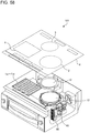
- Fig. 55 is a diagram showing a driver circuit of the induction cooker according to Embodiment 6.
- Fig. 55 illustrates the driver circuit 50e, which drives the first heating coil 1a and the second heating coil 1b.
- the driver circuit 50e includes a DC power supply circuit 22, an inverter circuit 23, a resonant capacitor 24a, a resonant capacitor 24b, a resonant capacitor 24c, and a switch 26.
- the DC power supply circuit 22 and the inverter circuit 23 are the same in configuration as those of Embodiment 1.
- the resonant capacitor 24a is connected in series to the first heating coil 1a.
- the resonant capacitor 24b is connected in series to the second heating coil 1b. Further, the resonant capacitor 24c is connected in parallel to the resonant capacitor 24b via the switch 26.
- the first heating coil 1a and the resonant capacitor 24a constitute a first resonant circuit.
- the second heating coil 1b, the resonant capacitor 24b, and the resonant capacitor 24c constitute a second resonant circuit.
- the first resonant circuit and the second resonant circuit are connected in parallel to each other.
- the first resonant circuit has a resonant frequency that depends on the inductance of the first heating coil 1a and the capacitance of the resonant capacitor 24a.
- the second resonant circuit has a resonant frequency that depends on the inductance of the second heating coil 1b and the capacitances of the resonant capacitor 24b and the resonant capacitor 24c.
- the switch 26 is turned on and off by the control unit 45. In a case where the switch 26 is in an on state, the resonant capacitor 24c is connected in parallel to the resonant capacitor 24b.
- the switch 26 is constituted, for example, by a power semiconductor, a relay, or other devices.
- the resonant frequency of the second resonant circuit is a first resonant frequency f1 that depends on the resultant capacitance of the resonant capacitor 24b and the resonant capacitor 24c and the inductance of the second heating coil 1b.
- the resonant frequency of the second resonant circuit is a second resonant frequency f2 that depends on the capacitance of the resonant capacitor 24b alone and the inductance of the second heating coil 1b. That is, the second resonant frequency f2, which is taken on in a case where the switch 26 is in an off state, is higher than the first resonant frequency f1, which is taken on in a case where the switch 26 is in an on state.
- the first heating coil 1a and the second heating coil 1b are configured such that their inductances take on substantially the same value.
- the resonant capacitor 24a, the resonant capacitor 24b, and the resonant capacitor 24b are configured such that the capacitance of the resonant capacitor 24a and the resultant capacitance of the resonant capacitor 24b and the resonant capacitor 24b take on substantially the same value. That is, the resonant frequency of the first resonant circuit takes on substantially the same value as the first resonant frequency f1, which the second resonant circuit takes on in a case where the switch 26 is in an on state.
- the coil current detection unit 25b detects an electric current flowing through the first heating coil 1a and outputs, to the control unit 45, a voltage signal representing a coil current value. Further, the coil current detection unit 25c detects an electric current flowing through the second heating coil 1b and outputs, to the control unit 45, a voltage signal representing a coil current value.
- Fig. 55 has described the driver circuit 50e, which drives the first heating coil 1a and the second heating coil 1b, the same configuration may be applied to the driver circuit 50f, which drives the third heating coil 1c and the fourth heating coil 1d.
- Fig. 55 has described a configuration in which two heating coils, namely the first heating coil 1a and the second heating coil 1b, are driven by one driver circuit, namely the driver circuit 50e, this is not intended to impose any limitation on the number of heating coils.
- the single driver circuit 50e may be configured to supply high-frequency power to two or more heating coils and may include a plurality of resonant capacitors forming a resonant circuit with each of the two or more heating coils, and at least one of the plurality of resonant capacitors may be configured to have a variable capacitance.
- the control unit 45 of the induction cooker 100 according to Embodiment 6 performs an operation of, by changing the capacitances of the resonant capacitors of the second resonant circuit and the driving frequency of the inverter circuit 23, changing the magnitude of electric power that is supplied to two heating coils, namely the first heating coil 1a and the second heating coil 1b.
- control unit 45 performs when, as described in Fig. 50 , a small-diameter heating target 5a1 is placed over the first heating coil 1a and the second heating coil 1b by a user.
- the load determination unit 46 of the control unit 45 performs a load determination process.
- the load determination unit 46 detects an input current from an output signal of the input current detection unit 25a.
- the control unit 45 detects coil currents from output signals of the coil current detection unit 25b and the coil current detection unit 25c.
- the load determination unit 46 determines, from the input current thus detected, the coil currents thus detected, and the load determination table stored in advance in the memory 48, whether a heating target is placed above each heating coil.
- the control unit 45 controls the driver circuit 50e and the driver circuit 50f according to a result of the load determination process and performs a heating operation appropriate to induction heating power and the cooking menu.
- the control unit 45 When a cooking menu in which the heating target 5a1 is subjected to cooking with heat in the convector mode is selected by an input from the operation unit 40, the control unit 45 performs a heating operation of producing convection in a liquid cooking target contained in the heating target 5a1.
- the control unit 45 brings the switch 26 of the driver circuit 50e into an off state. This causes the resonant frequency of the second resonant circuit to be changed from the first resonant frequency f1 to the second resonant frequency f2.
- the control unit 45 changes the magnitude of electric power that is supplied to the first heating coil 1a and the second heating coil 1b.
- Fig. 56 is a conceptual diagram showing a relationship between a driving frequency of the induction cooker according to Embodiment 6 and electric power that is supplied to the heating coils.
- the first resonant circuit and the second resonant circuit whose switch 26 is in an on state have a characteristic that peaks at the first resonant frequency f1 as indicated by an electric power characteristic 60.
- the second resonant circuit whose switch 26 is in an off state has a characteristic that peaks at the second resonant frequency f2 as indicated by an electric power characteristic 61.
- the control unit 45 has, as a preset operation region A, a range of frequencies that are equal to or higher than the first resonant frequency f1 and at which the electric power characteristic 60 is greater in electric power than the electric power characteristic 61. Further, the control unit 45 has, as a preset operation region B, a range of frequencies that are equal to or higher than the second resonant frequency f2. An upper-limit frequency of the operation region B is set at an upper limit value of an operating range of the driver circuit 50e, for example, 100 kHz.
- the driver circuit 50e When the driver circuit 50e is driven at a driving frequency falling within the range of the operation region A, the first resonant circuit and the second resonant circuit whose switch 26 is in an on state are supplied with more electric power than the second resonant circuit whose switch 26 is in an off state.
- the driver circuit 50e when the driver circuit 50e is driven at a driving frequency falling within the range of the operation region B, the first resonant circuit and the second resonant circuit whose switch 26 is in an on state is supplied with less electric power than the second resonant circuit whose switch 26 is in an off state.
- control unit 45 alternately switches the driving frequency of the inverter circuit 23 of the driver circuit 50e between a driving frequency falling within the range of the operation region A and a driving frequency falling within the range of the operation region B.
- the control unit 45 brings the switch 26 into an on state and changes the resonant frequency of the second resonant circuit to the first resonant frequency f1. As a result, the same electric power is supplied to the first heating coil 1a and the second heating coil 1b.
- Embodiment 6 two heating coils can be driven by the single driver circuit 50e. This makes it possible to make the driver circuit 50 simpler in configuration than those of the induction cookers 100 according to Embodiments 1 to 5.
- the magnitude of electric power that is supplied to two or more heating coils can be changed by changing the driving frequency of the driver circuit 50 and the capacitance of the second resonant circuit.
- a single driver circuit 50 may be configured to drive the first to fourth heating coils 1a to 1d, and a resonant capacitor forming a resonant circuit with each of the heating coils has a variable capacitance.
- the control unit 45 can arbitrarily change the magnitude of electric power that is supplied to two or more heating coils.
- Fig. 57 is a plan view schematically showing a plurality of heating coils of an induction cooker according to Modification 1.
- the first to fourth heating coils 1a to 1d may be aligned in one row, for example, in a longitudinal direction of the top plate 4. This configuration makes it possible to perform an operation that is the same as those of Embodiments 1 to 6 and bring about effects that are the same as those of Embodiments 1 to 6.
- Embodiments 1 to 6 has described a configuration in which the induction cooker 100 includes four heating coils, namely the first to fourth heating coils 1a to 1d, this is not intended to impose any limitation on the present invention.
- a configuration may be provided such that a plurality of heating openings are provided and a plurality of heating coils are aligned in one row for one of the plurality of heating openings.
- Fig. 58 is an exploded perspective view showing an induction cooker according to Modification 2.
- the first to fourth heating coils 1a to 1d may be aligned in one row below the first heating opening 1.
- a heating coil 12 disposed below the second heating opening 2 and a heating coil 13 disposed below the third heating opening 3 are constituted, for example, by circular coils.
Landscapes
- Physics & Mathematics (AREA)
- Electromagnetism (AREA)
- Engineering & Computer Science (AREA)
- Power Engineering (AREA)
- Induction Heating Cooking Devices (AREA)
Applications Claiming Priority (1)
| Application Number | Priority Date | Filing Date | Title |
|---|---|---|---|
| PCT/JP2018/010610 WO2019176110A1 (ja) | 2018-03-16 | 2018-03-16 | 誘導加熱調理器 |
Publications (3)
| Publication Number | Publication Date |
|---|---|
| EP3768043A1 true EP3768043A1 (de) | 2021-01-20 |
| EP3768043A4 EP3768043A4 (de) | 2021-03-17 |
| EP3768043B1 EP3768043B1 (de) | 2024-08-14 |
Family
ID=67907067
Family Applications (1)
| Application Number | Title | Priority Date | Filing Date |
|---|---|---|---|
| EP18909385.9A Active EP3768043B1 (de) | 2018-03-16 | 2018-03-16 | Induktionserwärmungskocher |
Country Status (5)
| Country | Link |
|---|---|
| US (1) | US11659632B2 (de) |
| EP (1) | EP3768043B1 (de) |
| JP (1) | JP6991309B2 (de) |
| CN (1) | CN111837454B (de) |
| WO (1) | WO2019176110A1 (de) |
Families Citing this family (2)
| Publication number | Priority date | Publication date | Assignee | Title |
|---|---|---|---|---|
| JP2021154065A (ja) * | 2020-03-30 | 2021-10-07 | 三菱電機株式会社 | 加熱調理器 |
| US11910509B2 (en) * | 2021-03-02 | 2024-02-20 | Whirlpool Corporation | Method for improving accuracy in load curves acquisition on an induction cooktop |
Family Cites Families (24)
| Publication number | Priority date | Publication date | Assignee | Title |
|---|---|---|---|---|
| US3710062A (en) * | 1971-04-06 | 1973-01-09 | Environment One Corp | Metal base cookware induction heating apparatus having improved power supply and gating control circuit using infra-red temperature sensor and improved induction heating coil arrangement |
| US3786222A (en) * | 1972-04-19 | 1974-01-15 | Gen Electric | Metallic foil induction cooking |
| JP2978069B2 (ja) * | 1994-09-06 | 1999-11-15 | 島田理化工業株式会社 | 電磁調理器 |
| DE19945297A1 (de) * | 1999-09-22 | 2001-03-29 | Diehl Ako Stiftung Gmbh & Co | Topferkennung |
| JP4915278B2 (ja) * | 2007-05-15 | 2012-04-11 | 三菱電機株式会社 | 誘導加熱調理器 |
| JP4804450B2 (ja) | 2007-12-26 | 2011-11-02 | 三菱電機株式会社 | 誘導加熱調理器 |
| US9055615B2 (en) * | 2008-12-26 | 2015-06-09 | Panasonic Corporation | Induction heating cooker |
| WO2010089809A1 (ja) * | 2009-02-06 | 2010-08-12 | パナソニック株式会社 | 電磁調理器 |
| JP5358673B2 (ja) * | 2009-03-06 | 2013-12-04 | 三菱電機株式会社 | 誘導加熱調理器 |
| ES2640965T3 (es) * | 2010-09-03 | 2017-11-07 | Mitsubishi Electric Corporation | Aparato de cocción por inducción |
| JP5645577B2 (ja) * | 2010-10-04 | 2014-12-24 | 三菱電機株式会社 | 誘導加熱調理器 |
| KR101835714B1 (ko) * | 2011-04-01 | 2018-03-08 | 삼성전자주식회사 | 유도가열조리기 및 그 제어방법 |
| JP2013109889A (ja) * | 2011-11-18 | 2013-06-06 | Panasonic Corp | 誘導加熱装置 |
| JP5943683B2 (ja) | 2012-04-11 | 2016-07-05 | 三菱電機株式会社 | 誘導加熱装置 |
| JP6292485B2 (ja) | 2013-04-25 | 2018-03-14 | パナソニックIpマネジメント株式会社 | 誘導加熱調理器 |
| JP5561409B2 (ja) * | 2013-06-24 | 2014-07-30 | パナソニック株式会社 | 誘導加熱調理器 |
| EP2846607B1 (de) * | 2013-09-05 | 2016-05-18 | Electrolux Appliances Aktiebolag | Induktionskochfeld mit einer Kochstelle mit drei oder mehr Induktionsspulen und Verfahren zur Steuerung einer Kochstelle |
| JP5674896B2 (ja) * | 2013-10-29 | 2015-02-25 | 三菱電機株式会社 | 誘導加熱調理器 |
| CN204377176U (zh) * | 2014-10-24 | 2015-06-03 | 三菱电机株式会社 | 感应加热烹调器 |
| JP6528119B2 (ja) | 2015-04-15 | 2019-06-12 | パナソニックIpマネジメント株式会社 | 加熱調理器 |
| EP3297400B1 (de) * | 2015-05-14 | 2019-07-03 | Panasonic Intellectual Property Management Co., Ltd. | Kochutensil mit induktionserhitzung |
| JP6960568B2 (ja) * | 2015-11-13 | 2021-11-05 | パナソニックIpマネジメント株式会社 | 誘導加熱調理器 |
| EP3291642A1 (de) * | 2016-09-02 | 2018-03-07 | Electrolux Appliances Aktiebolag | Induktionskochplatte und verfahren zur steuerung eines kochbereichs |
| JP6395890B2 (ja) * | 2017-03-28 | 2018-09-26 | 三菱電機株式会社 | 誘導加熱調理器 |
-
2018
- 2018-03-16 WO PCT/JP2018/010610 patent/WO2019176110A1/ja active Application Filing
- 2018-03-16 JP JP2020506098A patent/JP6991309B2/ja active Active
- 2018-03-16 EP EP18909385.9A patent/EP3768043B1/de active Active
- 2018-03-16 CN CN201880091106.3A patent/CN111837454B/zh active Active
- 2018-03-16 US US16/970,817 patent/US11659632B2/en active Active
Also Published As
| Publication number | Publication date |
|---|---|
| CN111837454A (zh) | 2020-10-27 |
| US11659632B2 (en) | 2023-05-23 |
| EP3768043B1 (de) | 2024-08-14 |
| WO2019176110A1 (ja) | 2019-09-19 |
| EP3768043A4 (de) | 2021-03-17 |
| JPWO2019176110A1 (ja) | 2020-12-17 |
| JP6991309B2 (ja) | 2022-01-12 |
| US20210307124A1 (en) | 2021-09-30 |
| CN111837454B (zh) | 2022-08-09 |
Similar Documents
| Publication | Publication Date | Title |
|---|---|---|
| JP4864850B2 (ja) | 誘導加熱調理器 | |
| US9006621B2 (en) | Hob with several heating elements with energy efficiency control | |
| JP6559348B2 (ja) | 非接触電力伝送システム及び誘導加熱調理器 | |
| EP3768043B1 (de) | Induktionserwärmungskocher | |
| KR20110092070A (ko) | 유도가열 조리기기 | |
| JP6211175B2 (ja) | 誘導加熱調理器 | |
| JP6143815B2 (ja) | 電力変換装置、及び誘導加熱調理器 | |
| JP5807161B2 (ja) | 誘導加熱装置およびそれを用いた炊飯器 | |
| WO2019092803A1 (ja) | 誘導加熱調理器 | |
| JP5642035B2 (ja) | 誘導加熱調理器 | |
| JP6991304B2 (ja) | 誘導加熱調理器 | |
| JP7038812B2 (ja) | 誘導加熱調理器 | |
| JP7233390B2 (ja) | 誘導加熱コイルおよび誘導加熱装置 | |
| JP5734390B2 (ja) | 誘導加熱調理器 | |
| JP5674896B2 (ja) | 誘導加熱調理器 | |
| KR102165579B1 (ko) | 이종의 인버터 회로들을 포함하는 유도 가열 장치 | |
| JP5289537B2 (ja) | 誘導加熱調理器 | |
| JP5404743B2 (ja) | 誘導加熱調理器 | |
| JP5625296B2 (ja) | 誘導加熱装置 | |
| US11399417B2 (en) | Induction heating cooker | |
| WO2017081859A1 (ja) | 誘導加熱調理器 | |
| JP6818467B2 (ja) | 誘導加熱調理器 | |
| EP4106491A1 (de) | Induktionskochvorrichtung |
Legal Events
| Date | Code | Title | Description |
|---|---|---|---|
| STAA | Information on the status of an ep patent application or granted ep patent |
Free format text: STATUS: THE INTERNATIONAL PUBLICATION HAS BEEN MADE |
|
| PUAI | Public reference made under article 153(3) epc to a published international application that has entered the european phase |
Free format text: ORIGINAL CODE: 0009012 |
|
| STAA | Information on the status of an ep patent application or granted ep patent |
Free format text: STATUS: REQUEST FOR EXAMINATION WAS MADE |
|
| 17P | Request for examination filed |
Effective date: 20200909 |
|
| AK | Designated contracting states |
Kind code of ref document: A1 Designated state(s): AL AT BE BG CH CY CZ DE DK EE ES FI FR GB GR HR HU IE IS IT LI LT LU LV MC MK MT NL NO PL PT RO RS SE SI SK SM TR |
|
| AX | Request for extension of the european patent |
Extension state: BA ME |
|
| REG | Reference to a national code |
Ref country code: DE Ref legal event code: R079 Ref document number: 602018073228 Country of ref document: DE Free format text: PREVIOUS MAIN CLASS: H05B0006120000 Ipc: H05B0006060000 Ref country code: DE Ref legal event code: R079 Free format text: PREVIOUS MAIN CLASS: H05B0006120000 Ipc: H05B0006060000 |
|
| A4 | Supplementary search report drawn up and despatched |
Effective date: 20210212 |
|
| RIC1 | Information provided on ipc code assigned before grant |
Ipc: H05B 6/06 20060101AFI20210208BHEP |
|
| DAV | Request for validation of the european patent (deleted) | ||
| DAX | Request for extension of the european patent (deleted) | ||
| STAA | Information on the status of an ep patent application or granted ep patent |
Free format text: STATUS: EXAMINATION IS IN PROGRESS |
|
| 17Q | First examination report despatched |
Effective date: 20231010 |
|
| GRAP | Despatch of communication of intention to grant a patent |
Free format text: ORIGINAL CODE: EPIDOSNIGR1 |
|
| STAA | Information on the status of an ep patent application or granted ep patent |
Free format text: STATUS: GRANT OF PATENT IS INTENDED |
|
| INTG | Intention to grant announced |
Effective date: 20240322 |
|
| GRAS | Grant fee paid |
Free format text: ORIGINAL CODE: EPIDOSNIGR3 |
|
| GRAA | (expected) grant |
Free format text: ORIGINAL CODE: 0009210 |
|
| STAA | Information on the status of an ep patent application or granted ep patent |
Free format text: STATUS: THE PATENT HAS BEEN GRANTED |
|
| AK | Designated contracting states |
Kind code of ref document: B1 Designated state(s): AL AT BE BG CH CY CZ DE DK EE ES FI FR GB GR HR HU IE IS IT LI LT LU LV MC MK MT NL NO PL PT RO RS SE SI SK SM TR |
|
| REG | Reference to a national code |
Ref country code: GB Ref legal event code: FG4D |
|
| REG | Reference to a national code |
Ref country code: CH Ref legal event code: EP |
|
| REG | Reference to a national code |
Ref country code: DE Ref legal event code: R096 Ref document number: 602018073228 Country of ref document: DE |