EP3753787A1 - Véhicule automobile doté d'un recouvrement de compartiment pour loger des marchandises - Google Patents
Véhicule automobile doté d'un recouvrement de compartiment pour loger des marchandises Download PDFInfo
- Publication number
- EP3753787A1 EP3753787A1 EP20185415.5A EP20185415A EP3753787A1 EP 3753787 A1 EP3753787 A1 EP 3753787A1 EP 20185415 A EP20185415 A EP 20185415A EP 3753787 A1 EP3753787 A1 EP 3753787A1
- Authority
- EP
- European Patent Office
- Prior art keywords
- tailgate
- cargo space
- motor vehicle
- space cover
- transmission means
- Prior art date
- Legal status (The legal status is an assumption and is not a legal conclusion. Google has not performed a legal analysis and makes no representation as to the accuracy of the status listed.)
- Granted
Links
Images


Classifications
-
- B—PERFORMING OPERATIONS; TRANSPORTING
- B60—VEHICLES IN GENERAL
- B60R—VEHICLES, VEHICLE FITTINGS, OR VEHICLE PARTS, NOT OTHERWISE PROVIDED FOR
- B60R5/00—Compartments within vehicle body primarily intended or sufficiently spacious for trunks, suit-cases, or the like
- B60R5/04—Compartments within vehicle body primarily intended or sufficiently spacious for trunks, suit-cases, or the like arranged at rear of vehicle
- B60R5/044—Compartments within vehicle body primarily intended or sufficiently spacious for trunks, suit-cases, or the like arranged at rear of vehicle luggage covering means, e.g. parcel shelves
-
- B—PERFORMING OPERATIONS; TRANSPORTING
- B60—VEHICLES IN GENERAL
- B60R—VEHICLES, VEHICLE FITTINGS, OR VEHICLE PARTS, NOT OTHERWISE PROVIDED FOR
- B60R5/00—Compartments within vehicle body primarily intended or sufficiently spacious for trunks, suit-cases, or the like
- B60R5/04—Compartments within vehicle body primarily intended or sufficiently spacious for trunks, suit-cases, or the like arranged at rear of vehicle
Definitions
- the present invention relates to a motor vehicle with a cargo space cover according to the preamble of claim 1.
- Load space covers for motor vehicles for covering a load space located behind a seat of the motor vehicle and located within a passenger compartment are generally known.
- luggage compartment covers offer a privacy screen when the tailgate is closed, so that the inside of the luggage compartment cannot be seen from the outside when the tailgate is closed, and on the other hand they can also be pivoted to release access to the luggage compartment when the tailgate is opened, so that objects in the loading space can be placed or removed from it without parts of the loading space cover having to be removed or moved away manually.
- a closed loading space cover advantageously reduces the transmission of undesired noises from the loading space or the rear area of the motor vehicle into the passenger compartment and thus improves its NVH properties (noise, vibration, harshness).
- Such cargo space covers are pivotably mounted with their front end area on the vehicle body, for example on side parts of the cargo space in the area of a rear seat backrest upper edge, and with their rear end area connected to the tailgate via a strap or pull cord attached to each side of the cargo space cover, so that the When swiveling the tailgate up and back, the cargo space cover is also pivoted upwards in order to enable access to the cargo space.
- Such cargo space covers for motor vehicles disclose, for example, the DE 10 2014 224 887 A1 and the US 8 528 957 B2 (also DE 10 2012 210 964 A1 ).
- FIG US 8 172 296 B2 A variant of a loading space cover for a motor vehicle that is very similar to this is also shown in FIG US 8 172 296 B2 , the cargo space cover here additionally being divided into a front cover section and a rear cover section is divided in order to enlarge the access area to the cargo space of the motor vehicle and thereby simplify the introduction and removal of larger objects in or from the cargo space.
- the front cover portion of the trunk cover is attached to the motor vehicle as described above.
- the rear cover section is firmly connected to the tailgate so that it moves completely with the tailgate and only adjoins the front cover section of the load compartment cover when the tailgate is closed in such a way that both sections form a single, flat, horizontal surface.
- FIG JP 2003-2120 A A cargo space cover that is rigidly connected to the tailgate of a motor vehicle relative to the latter is also shown in FIG JP 2003-2120 A .
- the cargo space cover is formed from a frame spanning a net.
- the attachment of the trunk cover to the tailgate provides on each vehicle side of the tailgate a strut that is attached to the inside of the tailgate and extends downwards with a hook-shaped free end that is detachable with a recess formed in a side part of the frame of the trunk cover on the underside Can be brought into engagement.
- On the rear part of the frame pins are provided which can be inserted into corresponding recesses in the tailgate.
- the frame of the load compartment cover can be lifted out of the hooks of the side struts and then the pins can be pulled out of the receptacles in the tailgate.
- the cargo space cover covers a cargo space of the motor vehicle located behind a vehicle seat and located within a passenger compartment.
- the load compartment cover does not hang vertically downwards due to gravity when the tailgate is open and obstructs access to the load compartment, it is pulled in this state by the front and vehicle body connection at a certain angle against the vertical direction in the direction of the passenger compartment to enlarge the access area to the hold.
- the DE 196 04 214 A1 provides for this purpose a force transmission means that is elastic in its longitudinal extension in the form of a rubber band, which is fastened at one end to the vehicle body, in particular to the vehicle floor, and at the other end to the front section of the cargo space cover.
- a force transmission means that is elastic in its longitudinal extension in the form of a rubber band, which is fastened at one end to the vehicle body, in particular to the vehicle floor, and at the other end to the front section of the cargo space cover.
- the rubber band is deflected along its course between the vehicle floor and the cargo space cover on a deflection means attached to a rear side of a vehicle seat.
- the front section of the cargo space cover is fastened to a roof structure of the vehicle body by means of rope-shaped force transmission means, which pull the front section of the cargo space cover towards the roof structure when the tailgate is open.
- the power transmission cables can be hooked into eyelets provided on the roof structure.
- the FR 2 819 459 A1 suggests attaching a rope-like power transmission means to the front section of the cargo space cover and to a side wall section of a vehicle body, the power transmission cable being deflected at a loop-like deflection means attached to the tailgate, through which the power transmission cable passes and through which it slides depending on the opening state of the tailgate can to pull the cargo space cover in the fully open state of the tailgate in the direction of the tailgate.
- the pivotable connection of the rear section of the cargo space cover provides a hook-and-eye connection, with a hook-shaped, arc-shaped one fastened to the tailgate Holding means engages in an opening of an eyelet provided on the cargo hold cover.
- the eyelet opening first slides along the curved hook section in order to enable the cargo space cover to pivot relative to the tailgate in order to finally hit an end stop of the hook that forms a form fit with the eyelet when the tailgate is fully open.
- the front-side fastening of the load compartment cover on the vehicle body is first loosened in order to be able to pivot the load compartment cover manually into a vertical position when the tailgate is open, in which the eye can be pushed over the end stop of the hook .
- the DE 20 2015 005 733 U1 discloses a parcel shelf for the upper limit and covering of a trunk of a motor vehicle comprising bearing elements for movably mounting the parcel shelf on a front end region of the parcel shelf, and counter bearing elements to be attached to a motor vehicle, one bearing element being insertable into the counter bearing element via a bearing slot of a counter bearing element.
- bearing elements and the counter-bearing elements are designed in such a way that in a locking position in which the bearing elements are received in the counter-bearing elements, the bearing elements and counter-bearing elements can be moved relative to one another in a direction that is essentially vertical to a pivot axis of the bearing elements by the bearing elements through additional openings from the counter-bearing elements or the counter-bearing elements can be moved out of the bearing elements (through additional openings, so that after moving out the mounting of the bearing elements on the counter-bearing elements is canceled in an unlocked position.
- the present invention is based on the object of creating a motor vehicle with a cargo space cover for a cargo space located behind a seat of the motor vehicle and located within a passenger compartment, the motor vehicle providing the greatest possible access to the cargo space when the tailgate is open in order to allow the vehicle to be brought in and removing large objects in and out of the hold facilitate.
- the mechanism for releasing and closing the access to the cargo space should also have a simple and thus inexpensive to manufacture structure.
- a motor vehicle has a tailgate that can be swung open to the rear and on which, with its rear end region facing the tailgate, a cargo space cover for covering a cargo space located behind a seat and located inside a passenger compartment is held pivotably about a pivot axis. So that the tailgate can be pivoted upwards towards the rear, it can be fastened in a manner known per se at its upper end region to a vehicle body, for example to the vehicle roof, so that it can pivot about a vehicle transverse axis.
- the cargo space cover is also held in an area spaced apart from the pivot axis on a vehicle body via at least one force transmission means, the force transmission means pivoting the cargo space cover when the tailgate is pivoted open, releasing access to the cargo space towards the tailgate.
- the force transmission means is deflected at a force deflection means attached to the tailgate. This is to be understood as meaning that the force action direction of the force transmission means is changed by the force deflection means from a first direction to a second direction different from the first direction.
- the power transmission means is a pull rope and the power deflection means is an on Power transmission means attached, diagonal or transverse to the power transmission means deflection cable.
- the cargo space cover is pulled towards the tailgate when the tailgate is pivoted open and is held essentially parallel to the tailgate after the tailgate has been pivoted open.
- the size of the access to the cargo space is thus only determined by the opening angle of the tailgate, since after the tailgate has been completely pivoted open, no area of the cargo space cover is arranged to reduce the access area to the cargo space.
- the cargo space cover completely closes the access to the cargo space in a conventional manner, so that the inside of the cargo space cannot be seen from the outside when the tailgate is closed.
- the invention thus provides the greatest possible access to the cargo space when the tailgate is open, so that the introduction and removal of large objects into and out of the cargo space is also made much easier.
- the pivoting mechanism of the loading space cover for opening and closing the access to the loading space can have a very simple and inexpensive construction, since the loading space cover can only be attached to the tailgate in a pivotable manner on the one hand and the power transmission means between the vehicle body and the loading space cover, deflected via the the tailgate attached force deflection means is arranged and a connection holding the cargo space cover on the vehicle body is provided.
- the deflection cable can be attached to the power transmission means via a fixed connection that does not allow any relative movement between the power transmission means and the power deflection means, so that no friction or frictional forces occur between the power transmission means and the power deflection means during the upward and downward pivoting movement of the tailgate.
- the force deflection of the force transmission means by means of the deflection pull cable firmly connected to it is particularly cost-effective
- the non-moving connection can be, for example, a plug-in, clamping, clip or sewing connection, or it can also be produced by a material connection technology, for example by gluing.
- the power transmission means are designed as a pull rope or tension band and the force deflection means as a deflection rope or deflection band. Both the power transmission means and the power deflection means are accordingly designed to only transmit tensile forces. This considerably simplifies the construction of the motor vehicle with a cargo space cover, since the force transmission means and the force deflection means are only to be designed for the transmission of tensile forces and not also for the transmission of thrust forces.
- the pivoting of the cargo space cover to release access to the cargo space during the pivoting of the tailgate into its open position can take place by a tensile force transmitted by the force transmission means between the vehicle body and the cargo space cover and by a tensile force transmitted by the force deflection means between the tailgate and the force transmission means, during the pivoting back the loading space cover for closing the access to the loading space during the pivoting of the tailgate into its closed position with the aid of the force of gravity acting on the loading space cover can take place.
- This structure can be implemented with simple, inexpensive means.
- an advantageous embodiment of the invention provides that the power transmission means and / or the power deflection means in each case The direction of force transmission is / are essentially not elastic or inelastic.
- the region of the cargo space cover which is spaced apart from the pivot axis and to which the force transmission means is connected to the cargo space cover is a front end region of the cargo space cover.
- the front end area can, for example, be about 1/3 of the longitudinal extent of the cargo space cover in the longitudinal direction of the vehicle have less, preferably for example about 1/4 and particularly preferably about 1/5 of the entire longitudinal extent of the cargo space cover in the longitudinal direction of the vehicle.
- a further advantageous embodiment of the invention provides that the vehicle body-side connection of the power transmission means to a vehicle pillar in front of the tailgate, in particular a vehicle pillar immediately in front of the tailgate, such as a C-pillar or D-pillar.
- the power transmission means can be routed directly to the power deflection means without further force deflection means having to be provided for guiding the power transmission means from its connection point on the vehicle body side to the power deflection means on the tailgate side. This simplifies the structure considerably.
- a still further simplification of the motor vehicle structure is given according to a further advantageous embodiment of the invention in that the force transmission means and the force deflection means are arranged in the passenger compartment and are therefore also accessible from this. For example, they can be replaced easily and without great effort in the event of maintenance.
- the arrangement of the power transmission means for example, on or along an inner side of the vehicle body surrounding the passenger compartment, is also possible in a simple manner and without great effort.
- Temporary dismantling of the cargo space cover for example for the transport of particularly bulky objects, can also be carried out easily in this way.
- the cargo space cover is releasably attached to the tailgate and the force transmission means is releasably fastened to the cargo space cover and / or releasably fastened to the vehicle body and the force deflection means is releasably fastened to the tailgate and / or releasably fastened to the force transmission means.
- the cargo space cover can thus be completely removed from the passenger compartment of the motor vehicle if necessary.
- At least one hook connection which connects the tailgate to the cargo space cover and fixes the pivot axis is provided, which has a hook-shaped holding means and a counter-holding means that can be brought into engagement therewith. It should be understood that for this purpose either the hook-shaped holding means is attached to the tailgate and the counter-holding means is fastened to the end region of the cargo space cover or the hook-shaped holding means is fastened to the end region of the cargo-space cover and the counter-holding means is fastened to the tailgate.
- a hook-shaped holding means in the context of the present invention is to be understood as any means (hereinafter also referred to as a hook for the sake of simplicity) that is essentially U-, J- or L-shaped, that is accordingly curved and / or angularly curved.
- the hook-shaped holding means is not completely closed around the circumference, such as a ring, but has a circumferential interruption which serves to introduce the counter-holding means into the hook and, if necessary, to remove it again in order to release the hook connection non-destructively.
- a counter-holding means is to be understood as any means that is suitable for entering into a releasable positive connection with the hook-shaped holding means in relation to at least one effective direction of a force acting on the counter-holding means.
- a force can for example be a tensile force acting between the hook and the counter-holding means.
- the counter-holding means can accordingly be designed, for example, as a completely closed ring or eyelet.
- the counter-holding means can, however, also be designed in the shape of a hook, as defined above, or also in the shape of a pin.
- the hook connection described above represents an easily and inexpensively realizable pivoting mechanism of the cargo space cover for opening and closing the cargo space access depending on the pivoting angle of the tailgate.
- the hook connection can be easily released manually and non-destructively in order to completely remove the cargo space cover from the passenger compartment of the motor vehicle if necessary to remove.
- the hook-shaped holding means has an inside holding surface with an ⁇ -shaped (omega-shaped) contour which circumferentially surrounds an outside of the counter-holding means engaging with the hook-shaped holding means in some areas.
- the hook-shaped holding means is not completely closed on the periphery, but has a circumferential interruption via which the counter-holding means can be brought into engagement with the hook.
- an ⁇ -shaped contour of the inside holding surface of the hook-shaped holding means is to be understood as a contour which circumferentially surrounds the outside of the counter holding means engaging with the hook-shaped holding means at a circumferential angle greater than 180 degrees and less than 360 degrees . Accordingly, the direct distance between the two free peripheral ends of the holding surface, which limit the circumferential interruption of the hook-shaped holding means, also referred to herein as the opening width, is smaller than the inner diameter of the contour of the inside holding surface.
- an outer diameter of the counter-holding means engaged with the hook-shaped holding means is selected so that it is larger than the opening width of the hook-shaped holding means and the same size or smaller than the inner diameter of the hook-holding surface contour, a certain resistance force must be applied to insert the counter-holding means into the hook Overcome in order to push the counter-holding means through the smaller opening width of the hook compared to its outer diameter. The same applies to the reverse process, that is, when the counter-holding means is released from the hook-shaped holding means.
- the hook-shaped holding means must have a certain elasticity, especially in the area of the peripheral ends of the holding surface, for a non-destructive production and release of the hook connection, which allows at least a short-term, non-destructive, elastic widening of the opening width for passing through the counter-holding means.
- the configuration described above offers the advantage that once a hook connection has been established between the hook-shaped retaining means and the counter-retaining means received by it, it can only be released by overcoming a certain resistance force, so that secure, stable storage of the cargo space cover on the tailgate is ensured under normal operating conditions and only in the event of the occurrence of a force acting on the hook connection and overcoming the resistance force, the hook connection is released. A manual release of the hook connection is thus possible.
- a largest inside diameter of the inside holding surface of the hook-shaped holding means has a size that corresponds at least to the size of an outside diameter of the outside of the counter-holding means that can be brought into engagement with the hook-shaped holding means. This ensures that the counter-holding means can be pivoted easily in the hook-shaped holding means with low friction losses.
- the hook connection is designed in such a way that the hook-shaped holding means holds the counter-holding means in a form-fitting manner when the tailgate is swiveled open, and the counter-holding means from a predetermined force acting on the cargo space cover when the tailgate swings open opposite to the swiveling movement Size releases non-destructively.
- the form-fitting holding of the counter-holding means by the hook when the tailgate is swiveled up and backwards ensures that the load compartment cover also moves upwards together with the tailgate.
- the connection of the area of the cargo space cover spaced apart from the pivot axis to the vehicle body via the force transmission means causes the cargo space cover to pivot towards the tailgate, thereby increasing access to the cargo space of the motor vehicle.
- the force of gravity acting on the cargo space cover can be used advantageously to move the cargo space cover back into its intended position for covering the cargo space with the tailgate fully closed, so that the inside of the cargo space is not visible from the outside when the tailgate is closed.
- the cargo compartment cover is at the pivoting movement of the tailgate, for example with its front edge, against the oversized object, so that this counteracts a movement of the cargo space cover following the pivoting movement of the tailgate and hinders or blocks it.
- the cargo space cover can consequently in the further course of the closing movement of the tailgate between the object and the tailgate become trapped, as a result of which the oversized object in the cargo space of the motor vehicle could be damaged by the compressive force exerted on the cargo space cover by the tailgate.
- the hook-shaped holding means has a sliding surface spaced from an inside of the tailgate, along which the counter-holding means slides and is guided after being released by the hook-shaped holding means.
- the sliding surface which is spaced apart from the inside of the tailgate, considerably reduces the possibility that the end region of the cargo space cover facing the tailgate, when it moves relative to the tailgate, for example, comes into positive engagement with an element or component of the tailgate protruding from the inside of the tailgate, which again would lead to a large, possibly damaging force from the tailgate over the luggage compartment cover on the oversized object.
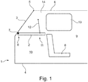
- FIG. 1 shows schematically a side sectional view of a rear area of an exemplary embodiment of a motor vehicle 1 with a cargo space cover 2 and a closed tailgate 3.
- FIG Fig. 1 a side sectional view through the motor vehicle 1 along its central longitudinal plane (corresponds to the plane of the drawing here) on the left side of the vehicle.
- the embodiment of the motor vehicle 1 shown here is in particular in its Fig. 1
- the rear area shown is constructed essentially symmetrically with respect to its center longitudinal plane, so that parts of the left-hand side of the vehicle described hereinafter in the same way on the in Fig. 1 Not to be recognized right vehicle side of the motor vehicle 1 are provided and arranged accordingly.
- the tailgate 3 can be swiveled open to the rear and upward about a tailgate pivot axis 5 fixed on a vehicle body 4, in particular on a roof area (see also FIG Fig. 2 ).
- Fig. 1 It can be seen that the cargo space cover 2 with its rear end region 6 facing the tailgate 3 is fastened to the tailgate 3 such that it can pivot about a pivot axis 7.
- the luggage compartment cover 2 covers in the in Fig. 1
- the closed state of the tailgate 3 shown in the illustrated closed state provides access to a cargo space 10 located behind a seat 8 of the motor vehicle 1, which here is a rear seat of the motor vehicle 1 arranged behind a front seat (not shown) of the motor vehicle 1 and located within a passenger compartment 9.
- the loading space cover 2 extends in the case of the in Fig.
- the illustrated state is essentially horizontal between its rear end area 6, which is held pivotably on the pivot axis 7, and a rear upper backrest edge of the seat 8, which is adjoined by a front end area 11 of the load compartment cover 2 spaced from the pivot axis 7.
- Fig. 1 It can be seen that, in the exemplary embodiment of the motor vehicle 1 shown here, the cargo space cover 2 is held on the vehicle body 4 via a force transmission means 12 in the form of a pull cable that is essentially non-elastic in the force transmission direction and only transmits tensile forces at the front end region 11 of the cargo space cover 2 spaced apart from the pivot axis 7 is.
- the power transmission means 12 is in the in Fig. 1
- the illustrated motor vehicle 1 is attached to a vehicle pillar 14 located behind a window 13 and directly in front of the tailgate 3, here a C pillar of the motor vehicle 1, and attached to the vehicle body 4.
- the D-pillar is preferred as a connection location instead of the C-pillar of the power transmission means 12 on the vehicle body 4 is used.
- Fig. 2 exhibits the rear area of the motor vehicle 1 Fig. 1 with the tailgate 3 open.
- the tailgate 3 is in one about the tailgate pivot axis 5 pivoted upwards to the rear, the load compartment cover 2 being pivoted by the power transmission means or pull rope 12 when the tailgate 3 is pivoted open, releasing access to the cargo space 10 towards the tailgate 3 and being held in the state shown for maximum access to provide for loading space 10.
- the force transmission means 12 which is essentially non-elastic in the force transmission direction and consequently does not lengthen in the force transmission direction, pulls the load compartment cover 2 upwards when the tailgate 3 is pivoted open, as a result of which the front end region 11 of the load compartment cover 2 about the pivot axis 7 in the direction of the tailgate 3 is pivoted.
- a power transmission means 12 is also connected to the front end region 11 of the right side of the load compartment cover 2 and to the right-hand vehicle body 4, in particular to the right C-pillar 14 of the motor vehicle 1.
- FIG. 10 shows a perspective view of the rear of the automobile 1 Fig. 1 with the tailgate 3 closed, from the rear left, whereby in the in Fig. 3 The view shown, the tailgate 3 cannot be seen in order to reveal the load space cover 2 and the load space 10.
- the motor vehicle 1 has, in a particularly advantageous manner, no lateral support pads, usually attached to the vehicle body 4, for the cargo space cover 2, on which a normal cargo space cover would rest in the closed state of the tailgate 3.
- the position of the cargo space cover 2 of the motor vehicle 1 is determined only by the force transmission means 12 and the pivotable holder on the tailgate 3.
- the access to the cargo space 10 can be further increased by omitting the lateral support pads for the cargo space cover 2. This also applies to all of the exemplary embodiments described below.
- FIG. 10 shows a perspective view of the rear of the automobile 1 Fig. 3 with the tailgate open from the rear left.
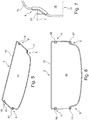
- FIG. 10 shows a perspective view of the cargo space cover 2 of the motor vehicle 1 Fig. 3 dar and Fig. 6 shows a top view of this cargo space cover 2.
- the cargo space cover 2 is formed from a frame 15 which surrounds the cargo space cover 2 and can be made of a light metal or a plastic, for example.
- the frame 15 spans a textile fabric 16 which forms the actual (storage or privacy protection) surface of the cargo space cover 2.
- the loading space cover 2 can advantageously be manufactured with a low weight and a low overall height, so that the loading space cover 2 can be mounted or dismantled on the motor vehicle 1 without great effort and, after dismantling, it is also accommodated in the motor vehicle 1 in a space-saving manner can be.
- the cargo space cover 2 has two loop-shaped counter-holding means 17 which can be hooked into a hook-shaped holding means (not shown here) in its rear end region 6 facing the tailgate 3. Furthermore, the loading space cover 2 has two further holding means 18 in its front end region 11, which is spaced apart from the rear end region 6, with each of which one of the force transmission means 12 can be connected.
- both the rear counter-holding means 17 and the two front holding means 18 are formed by a section of the frame 15 that is not covered by the textile fabric 16, so that no additional components need to be provided for this.
- Fig. 7 shows a partial view of a further exemplary embodiment of a load space cover 19, which can also be used in place of the load space cover 2 in all the exemplary embodiments of motor vehicles described here.
- the partial view shows a side part of the rear end region 6 of the cargo space cover 19.
- the load space cover 2 shown consists in that in the rear end region 6 of the load space cover 19 on both sides an eyelet-shaped counter-holding means 20 which can be hooked into a hook-shaped holding means (not shown here) is provided, which in this case is not formed by the frame 15 itself, but rather can be attached to the frame 15 as a separate component.
- the counter-holding means 20 can be placed on the frame 15, clamped and the like and / or glued to it.
- the advantage of this embodiment is that no recess has to be provided in the textile fabric 16 for the provision of the counter-holding means 20 and the (storage or privacy screen) surface of the loading space cover 19 can thus be completely closed.
- the pivot axis 7 is fixed by the counter holding means 20.
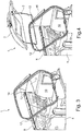
- FIG. 10 shows an interior perspective view of a rear side interior of the automobile 1 Fig. 1 with the trunk cover 19 closed when the tailgate is closed Fig. 7 represent.
- Fig. 9 shows an enlarged partial view Fig. 8 which shows an embodiment of a connection of the force transmission means 12 to the cargo space cover 19.
- Fig. 10 shows an enlarged partial view Fig. 8 which shows an embodiment of a pivotable mounting of the cargo space cover 19 on the tailgate 3.
- FIG. 11 FIG. 13 is a perspective sectional view along the line in FIG Fig. 10 Section line AA shown.
- the force transmission means 12 has an ⁇ -shaped (omega-shaped) connecting means 21 at its end on the load space cover, which can be releasably plugged directly onto the frame 15 of the load space cover 19.
- a special holding means 18, as in the luggage compartment cover 2 of the Figures 5 and 6 shown is not required in the cargo space cover 19.
- a second connection means 22 suitable for the connection to the vehicle body 4 or here with the C-pillar 14 is provided.
- the connecting means 21 shown on the loading space cover side and releasably attachable to the frame 15 of the loading space cover 19 can also be non-detachably connected to the loading space cover 19, for example sewn to the textile fabric 16.
- the connecting means 22 on the vehicle body side can be releasably or permanently connected to the vehicle body 4 or here the C-pillar 14, for example by means of a hook or clip connection.
- the vehicle body-side connecting means 22 is preferably releasably connected to the vehicle body 4 in order to ensure that the cargo space cover 19 can be easily removed from the motor vehicle 1.
- the hook connection which defines the pivot axis 7 and connects the cargo space cover 19 to the tailgate 3 in a pivotable manner can be clearly seen.
- the hook connection has a hook-shaped holding means 23 which is firmly connected to the tailgate 3 and with which the counter holding means 20 of the cargo space cover 19 can be brought into engagement.
- the hook-shaped holding means 23 in the illustrated embodiment of the motor vehicle 1 is designed and arranged in such a way that it holds the counter-holding means 20 of the cargo space cover 19 in a form-fitting manner when the tailgate 3 is pivoted open and the counter-holding means 20 during the pivoting movement of the tailgate 3 opposite to the pivoting movement from one of the Swiveling movement opposing, on the cargo space cover 19 acting force of a predetermined size releases non-destructively.
- the hook-shaped holding means 23 is essentially J-shaped in the area which can be brought into engagement with the counter holding means 20 of the cargo space cover 19, with a circumferential interruption 24 which is oriented towards the tailgate 3. Due to the interruption 24, the counter-holding means 20 of the cargo space cover 19 can be inserted into the hook and also detached from it again without being destroyed.
- Fig. 12 which shows a sectional side view through the cargo space 10 of the motor vehicle 1
- Fig. 8 shows along its central longitudinal plane (corresponds to the plane of the drawing) with an oversized object 25 located in the cargo space 10, however, a situation is shown when the tailgate 3 is pivoted into its closed position, in which the cargo space cover 19 with its front edge against due to the oversized object 25 in the cargo space 10 the object 25 will hit and consequently can be pinched between the object 25 and the inside of the tailgate 3, which could lead to damage to the object 25 as a result.
- the hook-shaped holding means 23 additionally has one to an inside of the Tailgate 3 spaced sliding surface 26, along which the counter holding means 20 of the loading space cover 19 slides and is guided after its release by the hook-shaped holding means 23.
- Fig. 14 Fig. 10 shows an enlarged partial view of the pivotable bracket Fig. 13 shortly after the engagement of the counter-holding means 20 of the cargo space cover 19 has been released from the hook-shaped holding means 23 Fig. 14 it can be seen that the hook-shaped holding means 23 has an inside holding surface with an ⁇ -shaped contour which circumferentially surrounds an outside of the counter-holding means 20 which is in engagement with the hook-shaped holding means 23.
- a largest inside diameter Di of the inside holding surface of the hook-shaped holding means 23 has a size which corresponds at least to the size of an outside diameter Da of the outside of the counter-holding means 20 that can be brought into engagement with the hook-shaped holding means 23 (Di ⁇ Da).
- the level of a resistance force can be determined, which must be overcome in order to release the counter-holding means 20 of the cargo space cover 19, which is in positive engagement with the hook-shaped holding means 23, from this engagement, as is shown in FIG Fig. 13 is shown.
- FIG. 15 shows a side sectional view of a rear area of a further exemplary embodiment of a motor vehicle 27 with a cargo space cover 19 and a closed tailgate 3.
- FIG Fig. 15 a side sectional view through the motor vehicle 27 along its central longitudinal plane (corresponds here to the plane of the drawing) on the left side of the vehicle.
- the exemplary embodiment of the motor vehicle 27 shown here is particularly illustrated in its FIG Fig. 15
- the rear area shown is constructed essentially symmetrically with respect to its center longitudinal plane, so that parts of the left-hand side of the vehicle described hereinafter in the same way on the in Fig. 27 undetectable right vehicle side of the motor vehicle 27 are provided and arranged accordingly.
- the tailgate 3 can be swiveled open to the rear and upward about a tailgate pivot axis 5 fixed on a vehicle body 4, in particular on a roof area (see also FIG Fig. 16 ).
- the luggage compartment cover 19 is fastened with its rear end region 6 facing the tailgate 3 to the tailgate 3 such that it can pivot about a pivot axis 7.
- the cargo space cover 19 covers in the in Fig. 15
- the closed state of the tailgate 3 shown in the figure provides access to a cargo space 10 located behind a seat 8 of the motor vehicle 27, which is here a rear seat of the motor vehicle 27 located behind a front seat (not shown) of the motor vehicle 27 and located within a passenger compartment 9.
- the loading space cover 19 extends in the case of the in Fig.
- the illustrated state is essentially horizontal between its rear end region 6, which is held pivotably on the pivot axis 7, and a rear upper edge of the seat backrest 8, which is adjoined by a front end region 11 of the load compartment cover 19 spaced from the pivot axis 7.
- Fig. 15 It can be seen that in the exemplary embodiment of the motor vehicle 27 shown here, the loading space cover 19 is held on the vehicle body 4 via a force transmission means 12 in the form of a tension cable that is essentially non-elastic in the direction of force transmission and only transmits tensile forces at the front end region 11 of the load space cover 19 spaced apart from the pivot axis 7 is.
- the power transmission means 12 is in the in Fig. 15
- the illustrated motor vehicle 27 is attached to a vehicle pillar 28 located behind a window 13 and directly in front of the tailgate 3, here a D pillar of the motor vehicle 27, and attached to the vehicle body 4. It is to be understood that if there is only one C-pillar directly in front of the tailgate 3 in a motor vehicle, this C-pillar instead of the D-pillar 28 is preferably used as a connection point of the power transmission means 12 on the vehicle body 4.
- the force transmission means 12 in the motor vehicle 27 is additionally deflected at a force deflection means 29 attached to the tailgate 3.
- the force transmission means 12 is a traction cable and the force deflection means 29 is a deflection cable which is attached to the force transmission means 12 and runs obliquely or transversely to the force transmission means 12.
- Fig. 16 exhibits the rear of the motor vehicle 27 Fig. 15 with the tailgate 3 open.
- the tailgate 3 is in a state pivoted upwards around the tailgate pivot axis 5, with the cargo space cover 19 providing access to the cargo space 10 through the power transmission means or pull cable 12 when the tailgate 3 is pivoted open is pivoted releasing to the tailgate 3 and is held in the state shown.
- the force deflection means 29 causes the power transmission means 12 to be pulled further upwards in the open position of the tailgate 3, as a result of which the cargo space cover 19 also pivots further about the pivot axis 7 in the direction of the tailgate 3. This provides the greatest possible access to the cargo space 10.
- the load space cover 19 when the tailgate 3 is pivoted open Pull up to the front, whereby the front end region 11 of the cargo space cover 19 is pivoted about the pivot axis 7 in the direction of the tailgate 3.
- Fig. 15 and 16 represent only the left side of the vehicle of the motor vehicle 27, but the motor vehicle 27 is constructed essentially symmetrically, particularly in its illustrated rear area, it is to be understood that at the in the Fig. 15 and 16 right vehicle side of the motor vehicle 27, not shown, also a power transmission means 12 is connected to the front end region 11 of the right side of the cargo space cover 19 and to the right-hand vehicle body 4, in particular to the right D-pillar 28 of the motor vehicle 27, and the power transmission means 12 is also connected by a Power deflection means 29 attached to the right of the vehicle side of the tailgate 3 is deflected.
- FIG. 10 shows an interior perspective view of a rear side interior of the automobile 27 Fig. 15 when the tailgate is closed.
- the power transmission means 12 has an ⁇ -shaped (omega-shaped) connecting means 21 at its cargo space cover-side end, which can be releasably plugged directly onto the frame 15 of the cargo space cover 19.
- a special holding means 18, as in the case of the cargo space cover 2 of Figures 5 and 6 shown is not required in the cargo space cover 19.
- a second connection means 22 suitable for connection to the vehicle body 4 or here with the D-pillar 28 is provided.
- connection means 21 shown on the load space cover side and releasably attachable to the frame 15 of the load space cover 2 can also be non-detachably connected to the load space cover 19, for example sewn to the textile fabric 16.
- the connection means 22 on the vehicle body side can be releasably or permanently connected to the vehicle body 4 or here the D-pillar 28, for example by means of a hook or clip connection.
- the vehicle body-side connecting means 22 is preferably releasably connected to the vehicle body 4 in order to ensure that the cargo space cover 19 can be easily removed from the motor vehicle 27.
- Fig. 18 shows an enlarged partial view Fig. 17 which shows the power transmission means 12 and the power deflection means 29.
- the attachment of the force deflection means 29 to the force transmission means 12 can be detachable, for example by means of a plug, clamp or clip connection, or non-detachable, for example by sewing onto the power transmission means 12.
- a tailgate-side connecting means 30 of the force deflection means 29 can be designed similar to the vehicle body-side connecting means 22 of the power transmission means 12, so for example be releasably attached to the tailgate 3 by means of a hook or clip connection or non-releasably.
- FIG. 10 shows a plan view of the cargo space cover 2 Fig. 5 dar and Fig. 20 an enlarged partial view Fig. 19 which shows a further exemplary embodiment of a pivotable mounting of the cargo space cover 2 on a tailgate 3.
- the pivotable holder of the trunk cover 2 on the tailgate 3 has at least one hook connection that connects the tailgate 3 to the trunk cover 2 and fixes the pivot axis 7, a hook-shaped holding means 31 that is firmly connected to the tailgate 3 and that can be brought into engagement therewith Has counter holding means 17.
- the hook-shaped holding means 31 is essentially U-shaped and has a circumferential interruption 24 which is oriented towards the cargo space cover 2. Through the interruption 24, the counter-holding means 17 of the cargo space cover 2 can be inserted into the hook and also detached from it again without being destroyed.
- Fig. 21 Fig. 10 shows an enlarged partial view of the pivotable bracket Fig. 20 in this Fig. 21 it can be seen that the hook-shaped holding means 31 has an inside holding surface with an ⁇ -shaped contour which circumferentially surrounds an outer side of the counter-holding means 17 that can be brought into engagement with the hook-shaped holding means 31.
- a largest inside diameter Di of the inside holding surface of the hook-shaped holding means 31 has a size which corresponds at least to the size of an outside diameter Da of the outside of the counter-holding means 17 that can be brought into engagement with the hook-shaped holding means 31 (Di Da Da).
- the level of a resistance force can be determined via the difference between the opening width W and the inner diameter Di, the overcoming of which is necessary in order to release the counter-holding means 17 of the cargo space cover 2, which is in positive engagement with the hook-shaped holding means 31, from this engagement.
- FIG. 3 schematically shows a side sectional view of a rear area of yet another exemplary embodiment of a motor vehicle 32 with a cargo space cover 2 and a closed tailgate 3.
- FIG Fig. 22 a schematic side cross-sectional view through the motor vehicle 32 along its central longitudinal plane (here corresponds to the plane of the drawing) Fig. 22 is therefore the part of the left side of the vehicle, based on the forward direction of travel.
- the exemplary embodiment of the motor vehicle 32 shown here is constructed essentially symmetrically with respect to the central longitudinal plane, in particular in its illustrated rear region, so that parts of the left-hand side of the vehicle described below in the same way also on the in Fig. 22 not to be recognized right side of the vehicle are provided and arranged accordingly.
- the tailgate 3 can be swiveled open to the rear and upward about a tailgate pivot axis 5 fixed on a vehicle body 4, in particular on a roof area (see also FIG Fig. 23 ).
- the luggage compartment cover 2 is attached with its rear end region 6 to the tailgate 3 so that it can pivot about a pivot axis 7.
- the luggage compartment cover 2 covers in the in Fig. 22
- the closed state of the tailgate 3 shown in the illustrated closed state provides access to a cargo space 10 located behind a seat 8 of the motor vehicle 32, which is here a rear seat of the motor vehicle 32 arranged behind a front seat (not shown) of the motor vehicle 32 and located within a passenger compartment 9.
- the loading space cover 2 extends in the case of the in Fig. 22
- the illustrated state is essentially horizontal between its rear end area 6, which is held pivotably on the pivot axis 7, and a rear seat back upper edge of the seat 8, which is adjoined by a front end area 11 of the cargo space cover 2.
- Fig. 22 It can be seen that in the exemplary embodiment of the motor vehicle 32 shown here, the loading space cover 2 is held on the vehicle body 4 via a force transmission means 12 in the form of a pulling cable that is essentially non-elastic in the force transmission direction and only transmits tensile forces at the front end region 11 of the load space cover 2 spaced apart from the pivot axis 7 is.
- the power transmission means 12 is in the in Fig. 22
- the illustrated motor vehicle 32 is connected to a vehicle pillar 14 located behind a window 13 and directly in front of the tailgate, here a C pillar of the motor vehicle 32, and attached to the vehicle body 4.
- a force deflection means 33 which deflects the force transmission means 12, is arranged and attached to the tailgate 3 can be seen.
- the force deflection means 33 can be designed, for example, as an eyelet or as a deflection roller.
- Fig. 23 exhibits the rear of the motor vehicle 32 Fig. 22 with the tailgate 3 open.
- the tailgate 3 is in a state pivoted back and up about the tailgate pivot axis 5, the load compartment cover 2 providing access to the cargo space 10 through the power transmission means or pull cable 12 when the tailgate 3 is pivoted open is pivoted releasing and held in the state shown.
- the cargo space cover 2 is arranged essentially completely parallel to the tailgate 3 when the tailgate 3 is fully open, as in FIG Fig. 23 is shown. This is achieved in that the distance between the force deflection means 33 in FIG Fig.
- the illustrated closed state of the tailgate 3 and the connection point of the power transmission means 12 in the front end region 11 of the cargo space cover 2 corresponds approximately to the pivoting distance of the force deflection means 33 when the tailgate 3 is pivoted open, so that the pivoting movement of the tailgate 3 and the resulting displacement of the force deflection means 33 pulls the force transmission means 12 upwards, which is essentially non-elastic in the force transmission direction and consequently does not lengthen in the force transmission direction, as a result of which the front end region 11 of the cargo space cover 2 is pivoted about the pivot axis 7 in the direction of the tailgate 3.
- Fig. 22 and 23 represent only the left vehicle side of the motor vehicle 32, but the motor vehicle 32 is constructed essentially symmetrically, in particular in its illustrated rear area, it is to be understood that on the in the Fig. 22 and 23 right vehicle side, not shown, also a power transmission means 12 is connected to the front end area 11 of the right side of the cargo space cover 2 and to the right-hand vehicle body 4, in particular to the right C-pillar 14 of the motor vehicle 32, and the power transmission means 12 is also connected by a on the right side of the vehicle Tailgate 3 attached force deflection means 33 is guided or deflected.
- Fig. 24 shows a rear area of a further exemplary embodiment of a motor vehicle 34 with a cargo space cover 35 and an open tailgate 3 Fig. 24 the force transmission means 12, which are arranged on both sides of the cargo space cover 35 and which are also designed here as essentially inelastic pulling cables, can be seen.
- FIG. 10 shows an interior side view of the vehicle right side of the automobile 34 Fig. 24 with the tailgate 3 closed. It can be clearly seen that the force transmission means 12 is connected at one end to the front end region 11 of the cargo space cover 35 and is attached to the vehicle body 4 at the other end.
- the vehicle body-side connection of the power transmission means 12 to a D-pillar 28 of the motor vehicle 34 immediately in front of the tailgate 3, as in FIG Fig. 26 can be seen, which is a detailed view of the rear right area of the motor vehicle 34 Fig. 24 with the tailgate 3 open and additionally recognizable C-pillar 14 of the motor vehicle 34.
- the loading space cover 35 is detachably attached to the tailgate 3 and the force transmission means 12 is detachably attached to the loading space cover 35 and / or detachably to the vehicle body 4.
Applications Claiming Priority (3)
| Application Number | Priority Date | Filing Date | Title |
|---|---|---|---|
| DE102017206309.2A DE102017206309B4 (de) | 2017-04-12 | 2017-04-12 | Kraftfahrzeug mit einer Laderaumabdeckung |
| DE102018200940.6A DE102018200940A1 (de) | 2018-01-22 | 2018-01-22 | Kraftfahrzeug mit einer Laderaumabdeckung |
| EP18160714.4A EP3388287B1 (fr) | 2017-04-12 | 2018-03-08 | Véhicule automobile doté d'un recouvrement de compartiment pour loger des marchandises |
Related Parent Applications (2)
| Application Number | Title | Priority Date | Filing Date |
|---|---|---|---|
| EP18160714.4A Division EP3388287B1 (fr) | 2017-04-12 | 2018-03-08 | Véhicule automobile doté d'un recouvrement de compartiment pour loger des marchandises |
| EP18160714.4A Division-Into EP3388287B1 (fr) | 2017-04-12 | 2018-03-08 | Véhicule automobile doté d'un recouvrement de compartiment pour loger des marchandises |
Publications (2)
| Publication Number | Publication Date |
|---|---|
| EP3753787A1 true EP3753787A1 (fr) | 2020-12-23 |
| EP3753787B1 EP3753787B1 (fr) | 2021-11-10 |
Family
ID=61599068
Family Applications (2)
| Application Number | Title | Priority Date | Filing Date |
|---|---|---|---|
| EP18160714.4A Active EP3388287B1 (fr) | 2017-04-12 | 2018-03-08 | Véhicule automobile doté d'un recouvrement de compartiment pour loger des marchandises |
| EP20185415.5A Active EP3753787B1 (fr) | 2017-04-12 | 2018-03-08 | Véhicule automobile doté d'un recouvrement de compartiment pour loger des marchandises |
Family Applications Before (1)
| Application Number | Title | Priority Date | Filing Date |
|---|---|---|---|
| EP18160714.4A Active EP3388287B1 (fr) | 2017-04-12 | 2018-03-08 | Véhicule automobile doté d'un recouvrement de compartiment pour loger des marchandises |
Country Status (1)
| Country | Link |
|---|---|
| EP (2) | EP3388287B1 (fr) |
Citations (8)
| Publication number | Priority date | Publication date | Assignee | Title |
|---|---|---|---|---|
| DE19604214A1 (de) | 1995-02-15 | 1996-08-22 | Volkswagen Ag | Kraftfahrzeug mit einer Laderaumabdeckung |
| FR2819459A1 (fr) | 2001-01-17 | 2002-07-19 | Sai Automotive Sommer Ind | Dispositif de retenue et d'articulation d'une tablette arriere amovible de vehicule automobile |
| JP2003002120A (ja) | 2001-06-21 | 2003-01-08 | Honda Motor Co Ltd | 車両のリヤゲート構造 |
| US8172296B2 (en) | 2009-09-08 | 2012-05-08 | Honda Motor Co., Ltd. | Parcel shelf structure |
| DE102012210964A1 (de) | 2011-06-29 | 2013-01-03 | Ford Global Technologies, Llc | Frachtmanagementsystem |
| JP2013035380A (ja) | 2011-08-08 | 2013-02-21 | Mazda Motor Corp | 車両のトノボード装置 |
| DE102014224887A1 (de) | 2014-12-04 | 2016-06-09 | Bayerische Motoren Werke Aktiengesellschaft | Kraftfahrzeug |
| DE202015005733U1 (de) | 2015-08-12 | 2016-11-15 | GM Global Technology Operations LLC (n. d. Ges. d. Staates Delaware) | Hutablage sowie Kraftfahrzeug mit Hutablage |
-
2018
- 2018-03-08 EP EP18160714.4A patent/EP3388287B1/fr active Active
- 2018-03-08 EP EP20185415.5A patent/EP3753787B1/fr active Active
Patent Citations (9)
| Publication number | Priority date | Publication date | Assignee | Title |
|---|---|---|---|---|
| DE19604214A1 (de) | 1995-02-15 | 1996-08-22 | Volkswagen Ag | Kraftfahrzeug mit einer Laderaumabdeckung |
| FR2819459A1 (fr) | 2001-01-17 | 2002-07-19 | Sai Automotive Sommer Ind | Dispositif de retenue et d'articulation d'une tablette arriere amovible de vehicule automobile |
| JP2003002120A (ja) | 2001-06-21 | 2003-01-08 | Honda Motor Co Ltd | 車両のリヤゲート構造 |
| US8172296B2 (en) | 2009-09-08 | 2012-05-08 | Honda Motor Co., Ltd. | Parcel shelf structure |
| DE102012210964A1 (de) | 2011-06-29 | 2013-01-03 | Ford Global Technologies, Llc | Frachtmanagementsystem |
| US8528957B2 (en) | 2011-06-29 | 2013-09-10 | Ford Global Technologies, Llc | Cargo management system |
| JP2013035380A (ja) | 2011-08-08 | 2013-02-21 | Mazda Motor Corp | 車両のトノボード装置 |
| DE102014224887A1 (de) | 2014-12-04 | 2016-06-09 | Bayerische Motoren Werke Aktiengesellschaft | Kraftfahrzeug |
| DE202015005733U1 (de) | 2015-08-12 | 2016-11-15 | GM Global Technology Operations LLC (n. d. Ges. d. Staates Delaware) | Hutablage sowie Kraftfahrzeug mit Hutablage |
Also Published As
| Publication number | Publication date |
|---|---|
| EP3753787B1 (fr) | 2021-11-10 |
| EP3388287B1 (fr) | 2020-12-02 |
| EP3388287A1 (fr) | 2018-10-17 |
Similar Documents
| Publication | Publication Date | Title |
|---|---|---|
| DE102018200940A1 (de) | Kraftfahrzeug mit einer Laderaumabdeckung | |
| DE102012204383B4 (de) | Abteil mit einem hohldrehstab für eine verschlussplatte | |
| DE10044826B4 (de) | Verkleidung einer Hecktür eines Kraftfahrzeuges | |
| EP2877372B1 (fr) | Structure de barres de toit pour véhicule automobile | |
| EP3753787B1 (fr) | Véhicule automobile doté d'un recouvrement de compartiment pour loger des marchandises | |
| DE102017206309B4 (de) | Kraftfahrzeug mit einer Laderaumabdeckung | |
| DE10102662A1 (de) | Windschotteinrichtung | |
| DE19650768C2 (de) | Sicherheitsnetzanordnung mit vereinfachter Bedienung | |
| DE69924444T2 (de) | Schutzvorrichtung insbesondere Sicherheitsnetz für Kraftfahrzeuge | |
| EP2842841B1 (fr) | Structure et bâchage latérale d'un véhicule utilitaire | |
| DE102013019243B4 (de) | Seilbremse, Spannset und Vorhangsystem | |
| DE102015211334A1 (de) | Sicherheits-Verriegelungsvorrichtung in einem Kraftfahrzeug und Kraftfahrzeug mit einer derartigen Sicherheits-Verriegelungsvorrichtung | |
| DE102007045048B4 (de) | Einhängehaken | |
| DE102020109274B3 (de) | Zurröse mit Mittelstück zur Anordnung an einer Ladefläche eines Transportfahrzeuges | |
| EP3546260B1 (fr) | Élément de fermeture bâche, bâche et carrosserie | |
| DE102015109172B4 (de) | Nutzfahrzeugaufbau mit einer Plane, Nutzfahrzeug mit einem derartigen Nutzfahrzeugaufbau und Verfahren zur Herstellung eines Nutzfahrzeugaufbaus | |
| DE102009055836A1 (de) | Verschwenkbare Platte für ein Kraftfahrzeug und Kraftfahrzeug mit einer solchen verschwenkbaren Platte | |
| DE102018217068A1 (de) | Anordnung zur Befestigung eines Gepäckraumdeckels eines Kraftfahrzeugs an demselben sowie Kraftfahrzeug mit einer solchen Befestigungsanordnung | |
| DE102016120879B3 (de) | Laderaumtrennnetz mit Sicherheitsbefestigung | |
| DE202009007533U1 (de) | Befestigungseinrichtung | |
| DE102011122390B4 (de) | Rolloverschluss für eine Ablage eines Kraftfahrzeugs | |
| DE102006051645A1 (de) | Kraftfahrzeug mit einem Kofferraum | |
| DE102012108359A1 (de) | Nutzfahrzeug mit einem von einem Chassis getragenen, einen Laderaum umgrenzenden Planenaufbau | |
| DE102014222186B3 (de) | Einhängevorrichtung für eine Laderaumabtrennung in einem Fahrzeuginnenraum | |
| EP3034340B1 (fr) | Structure de vehicule dotee d'une bache coulissante |
Legal Events
| Date | Code | Title | Description |
|---|---|---|---|
| PUAI | Public reference made under article 153(3) epc to a published international application that has entered the european phase |
Free format text: ORIGINAL CODE: 0009012 |
|
| STAA | Information on the status of an ep patent application or granted ep patent |
Free format text: STATUS: THE APPLICATION HAS BEEN PUBLISHED |
|
| AC | Divisional application: reference to earlier application |
Ref document number: 3388287 Country of ref document: EP Kind code of ref document: P |
|
| AK | Designated contracting states |
Kind code of ref document: A1 Designated state(s): AL AT BE BG CH CY CZ DE DK EE ES FI FR GB GR HR HU IE IS IT LI LT LU LV MC MK MT NL NO PL PT RO RS SE SI SK SM TR |
|
| RIN1 | Information on inventor provided before grant (corrected) |
Inventor name: BAUMANN, MATTHIAS Inventor name: CAUSEMANN, CHRISTIAN Inventor name: SCHNEIDER, FRANK Inventor name: LOEWE, THOMAS Inventor name: KAATZ, SASCHA Inventor name: FUSS, CHRISTOPH |
|
| STAA | Information on the status of an ep patent application or granted ep patent |
Free format text: STATUS: REQUEST FOR EXAMINATION WAS MADE |
|
| 17P | Request for examination filed |
Effective date: 20210623 |
|
| RBV | Designated contracting states (corrected) |
Designated state(s): AL AT BE BG CH CY CZ DE DK EE ES FI FR GB GR HR HU IE IS IT LI LT LU LV MC MK MT NL NO PL PT RO RS SE SI SK SM TR |
|
| GRAP | Despatch of communication of intention to grant a patent |
Free format text: ORIGINAL CODE: EPIDOSNIGR1 |
|
| STAA | Information on the status of an ep patent application or granted ep patent |
Free format text: STATUS: GRANT OF PATENT IS INTENDED |
|
| INTG | Intention to grant announced |
Effective date: 20210830 |
|
| GRAS | Grant fee paid |
Free format text: ORIGINAL CODE: EPIDOSNIGR3 |
|
| GRAA | (expected) grant |
Free format text: ORIGINAL CODE: 0009210 |
|
| STAA | Information on the status of an ep patent application or granted ep patent |
Free format text: STATUS: THE PATENT HAS BEEN GRANTED |
|
| AC | Divisional application: reference to earlier application |
Ref document number: 3388287 Country of ref document: EP Kind code of ref document: P |
|
| AK | Designated contracting states |
Kind code of ref document: B1 Designated state(s): AL AT BE BG CH CY CZ DE DK EE ES FI FR GB GR HR HU IE IS IT LI LT LU LV MC MK MT NL NO PL PT RO RS SE SI SK SM TR |
|
| REG | Reference to a national code |
Ref country code: GB Ref legal event code: FG4D Free format text: NOT ENGLISH |
|
| REG | Reference to a national code |
Ref country code: AT Ref legal event code: REF Ref document number: 1445794 Country of ref document: AT Kind code of ref document: T Effective date: 20211115 Ref country code: CH Ref legal event code: EP |
|
| REG | Reference to a national code |
Ref country code: DE Ref legal event code: R096 Ref document number: 502018007838 Country of ref document: DE |
|
| REG | Reference to a national code |
Ref country code: IE Ref legal event code: FG4D Free format text: LANGUAGE OF EP DOCUMENT: GERMAN |
|
| REG | Reference to a national code |
Ref country code: LT Ref legal event code: MG9D |
|
| REG | Reference to a national code |
Ref country code: NL Ref legal event code: MP Effective date: 20211110 |
|
| PG25 | Lapsed in a contracting state [announced via postgrant information from national office to epo] |
Ref country code: RS Free format text: LAPSE BECAUSE OF FAILURE TO SUBMIT A TRANSLATION OF THE DESCRIPTION OR TO PAY THE FEE WITHIN THE PRESCRIBED TIME-LIMIT Effective date: 20211110 Ref country code: LT Free format text: LAPSE BECAUSE OF FAILURE TO SUBMIT A TRANSLATION OF THE DESCRIPTION OR TO PAY THE FEE WITHIN THE PRESCRIBED TIME-LIMIT Effective date: 20211110 Ref country code: FI Free format text: LAPSE BECAUSE OF FAILURE TO SUBMIT A TRANSLATION OF THE DESCRIPTION OR TO PAY THE FEE WITHIN THE PRESCRIBED TIME-LIMIT Effective date: 20211110 Ref country code: BG Free format text: LAPSE BECAUSE OF FAILURE TO SUBMIT A TRANSLATION OF THE DESCRIPTION OR TO PAY THE FEE WITHIN THE PRESCRIBED TIME-LIMIT Effective date: 20220210 |
|
| PG25 | Lapsed in a contracting state [announced via postgrant information from national office to epo] |
Ref country code: IS Free format text: LAPSE BECAUSE OF FAILURE TO SUBMIT A TRANSLATION OF THE DESCRIPTION OR TO PAY THE FEE WITHIN THE PRESCRIBED TIME-LIMIT Effective date: 20220310 Ref country code: SE Free format text: LAPSE BECAUSE OF FAILURE TO SUBMIT A TRANSLATION OF THE DESCRIPTION OR TO PAY THE FEE WITHIN THE PRESCRIBED TIME-LIMIT Effective date: 20211110 Ref country code: PT Free format text: LAPSE BECAUSE OF FAILURE TO SUBMIT A TRANSLATION OF THE DESCRIPTION OR TO PAY THE FEE WITHIN THE PRESCRIBED TIME-LIMIT Effective date: 20220310 Ref country code: PL Free format text: LAPSE BECAUSE OF FAILURE TO SUBMIT A TRANSLATION OF THE DESCRIPTION OR TO PAY THE FEE WITHIN THE PRESCRIBED TIME-LIMIT Effective date: 20211110 Ref country code: NO Free format text: LAPSE BECAUSE OF FAILURE TO SUBMIT A TRANSLATION OF THE DESCRIPTION OR TO PAY THE FEE WITHIN THE PRESCRIBED TIME-LIMIT Effective date: 20220210 Ref country code: NL Free format text: LAPSE BECAUSE OF FAILURE TO SUBMIT A TRANSLATION OF THE DESCRIPTION OR TO PAY THE FEE WITHIN THE PRESCRIBED TIME-LIMIT Effective date: 20211110 Ref country code: LV Free format text: LAPSE BECAUSE OF FAILURE TO SUBMIT A TRANSLATION OF THE DESCRIPTION OR TO PAY THE FEE WITHIN THE PRESCRIBED TIME-LIMIT Effective date: 20211110 Ref country code: HR Free format text: LAPSE BECAUSE OF FAILURE TO SUBMIT A TRANSLATION OF THE DESCRIPTION OR TO PAY THE FEE WITHIN THE PRESCRIBED TIME-LIMIT Effective date: 20211110 Ref country code: GR Free format text: LAPSE BECAUSE OF FAILURE TO SUBMIT A TRANSLATION OF THE DESCRIPTION OR TO PAY THE FEE WITHIN THE PRESCRIBED TIME-LIMIT Effective date: 20220211 |
|
| PG25 | Lapsed in a contracting state [announced via postgrant information from national office to epo] |
Ref country code: SM Free format text: LAPSE BECAUSE OF FAILURE TO SUBMIT A TRANSLATION OF THE DESCRIPTION OR TO PAY THE FEE WITHIN THE PRESCRIBED TIME-LIMIT Effective date: 20211110 Ref country code: SK Free format text: LAPSE BECAUSE OF FAILURE TO SUBMIT A TRANSLATION OF THE DESCRIPTION OR TO PAY THE FEE WITHIN THE PRESCRIBED TIME-LIMIT Effective date: 20211110 Ref country code: RO Free format text: LAPSE BECAUSE OF FAILURE TO SUBMIT A TRANSLATION OF THE DESCRIPTION OR TO PAY THE FEE WITHIN THE PRESCRIBED TIME-LIMIT Effective date: 20211110 Ref country code: ES Free format text: LAPSE BECAUSE OF FAILURE TO SUBMIT A TRANSLATION OF THE DESCRIPTION OR TO PAY THE FEE WITHIN THE PRESCRIBED TIME-LIMIT Effective date: 20211110 Ref country code: EE Free format text: LAPSE BECAUSE OF FAILURE TO SUBMIT A TRANSLATION OF THE DESCRIPTION OR TO PAY THE FEE WITHIN THE PRESCRIBED TIME-LIMIT Effective date: 20211110 Ref country code: DK Free format text: LAPSE BECAUSE OF FAILURE TO SUBMIT A TRANSLATION OF THE DESCRIPTION OR TO PAY THE FEE WITHIN THE PRESCRIBED TIME-LIMIT Effective date: 20211110 Ref country code: CZ Free format text: LAPSE BECAUSE OF FAILURE TO SUBMIT A TRANSLATION OF THE DESCRIPTION OR TO PAY THE FEE WITHIN THE PRESCRIBED TIME-LIMIT Effective date: 20211110 |
|
| REG | Reference to a national code |
Ref country code: DE Ref legal event code: R097 Ref document number: 502018007838 Country of ref document: DE |
|
| PLBE | No opposition filed within time limit |
Free format text: ORIGINAL CODE: 0009261 |
|
| STAA | Information on the status of an ep patent application or granted ep patent |
Free format text: STATUS: NO OPPOSITION FILED WITHIN TIME LIMIT |
|
| 26N | No opposition filed |
Effective date: 20220811 |
|
| PG25 | Lapsed in a contracting state [announced via postgrant information from national office to epo] |
Ref country code: MC Free format text: LAPSE BECAUSE OF FAILURE TO SUBMIT A TRANSLATION OF THE DESCRIPTION OR TO PAY THE FEE WITHIN THE PRESCRIBED TIME-LIMIT Effective date: 20211110 Ref country code: AL Free format text: LAPSE BECAUSE OF FAILURE TO SUBMIT A TRANSLATION OF THE DESCRIPTION OR TO PAY THE FEE WITHIN THE PRESCRIBED TIME-LIMIT Effective date: 20211110 |
|
| REG | Reference to a national code |
Ref country code: CH Ref legal event code: PL |
|
| PG25 | Lapsed in a contracting state [announced via postgrant information from national office to epo] |
Ref country code: SI Free format text: LAPSE BECAUSE OF FAILURE TO SUBMIT A TRANSLATION OF THE DESCRIPTION OR TO PAY THE FEE WITHIN THE PRESCRIBED TIME-LIMIT Effective date: 20211110 |
|
| REG | Reference to a national code |
Ref country code: BE Ref legal event code: MM Effective date: 20220331 |
|
| PG25 | Lapsed in a contracting state [announced via postgrant information from national office to epo] |
Ref country code: LU Free format text: LAPSE BECAUSE OF NON-PAYMENT OF DUE FEES Effective date: 20220308 Ref country code: LI Free format text: LAPSE BECAUSE OF NON-PAYMENT OF DUE FEES Effective date: 20220331 Ref country code: IE Free format text: LAPSE BECAUSE OF NON-PAYMENT OF DUE FEES Effective date: 20220308 Ref country code: CH Free format text: LAPSE BECAUSE OF NON-PAYMENT OF DUE FEES Effective date: 20220331 |
|
| PG25 | Lapsed in a contracting state [announced via postgrant information from national office to epo] |
Ref country code: BE Free format text: LAPSE BECAUSE OF NON-PAYMENT OF DUE FEES Effective date: 20220331 |
|
| PGFP | Annual fee paid to national office [announced via postgrant information from national office to epo] |
Ref country code: FR Payment date: 20230209 Year of fee payment: 6 |
|
| PG25 | Lapsed in a contracting state [announced via postgrant information from national office to epo] |
Ref country code: IT Free format text: LAPSE BECAUSE OF FAILURE TO SUBMIT A TRANSLATION OF THE DESCRIPTION OR TO PAY THE FEE WITHIN THE PRESCRIBED TIME-LIMIT Effective date: 20211110 |
|
| PGFP | Annual fee paid to national office [announced via postgrant information from national office to epo] |
Ref country code: GB Payment date: 20230208 Year of fee payment: 6 Ref country code: DE Payment date: 20230210 Year of fee payment: 6 |
|
| P01 | Opt-out of the competence of the unified patent court (upc) registered |
Effective date: 20230620 |