EP3746847B1 - Erfassung der grösse eines druckmediums unter verwendung von sensoren, die entlang eines papierwegs verfügbar sind - Google Patents
Erfassung der grösse eines druckmediums unter verwendung von sensoren, die entlang eines papierwegs verfügbar sind Download PDFInfo
- Publication number
- EP3746847B1 EP3746847B1 EP19777720.4A EP19777720A EP3746847B1 EP 3746847 B1 EP3746847 B1 EP 3746847B1 EP 19777720 A EP19777720 A EP 19777720A EP 3746847 B1 EP3746847 B1 EP 3746847B1
- Authority
- EP
- European Patent Office
- Prior art keywords
- print medium
- state
- overload
- feeder
- Prior art date
- Legal status (The legal status is an assumption and is not a legal conclusion. Google has not performed a legal analysis and makes no representation as to the accuracy of the status listed.)
- Active
Links
Images

Classifications
-
- G—PHYSICS
- G03—PHOTOGRAPHY; CINEMATOGRAPHY; ANALOGOUS TECHNIQUES USING WAVES OTHER THAN OPTICAL WAVES; ELECTROGRAPHY; HOLOGRAPHY
- G03G—ELECTROGRAPHY; ELECTROPHOTOGRAPHY; MAGNETOGRAPHY
- G03G15/00—Apparatus for electrographic processes using a charge pattern
- G03G15/70—Detecting malfunctions relating to paper handling, e.g. jams
-
- G—PHYSICS
- G03—PHOTOGRAPHY; CINEMATOGRAPHY; ANALOGOUS TECHNIQUES USING WAVES OTHER THAN OPTICAL WAVES; ELECTROGRAPHY; HOLOGRAPHY
- G03G—ELECTROGRAPHY; ELECTROPHOTOGRAPHY; MAGNETOGRAPHY
- G03G15/00—Apparatus for electrographic processes using a charge pattern
- G03G15/50—Machine control of apparatus for electrographic processes using a charge pattern, e.g. regulating differents parts of the machine, multimode copiers, microprocessor control
- G03G15/5029—Machine control of apparatus for electrographic processes using a charge pattern, e.g. regulating differents parts of the machine, multimode copiers, microprocessor control by measuring the copy material characteristics, e.g. weight, thickness
-
- B—PERFORMING OPERATIONS; TRANSPORTING
- B65—CONVEYING; PACKING; STORING; HANDLING THIN OR FILAMENTARY MATERIAL
- B65H—HANDLING THIN OR FILAMENTARY MATERIAL, e.g. SHEETS, WEBS, CABLES
- B65H1/00—Supports or magazines for piles from which articles are to be separated
- B65H1/04—Supports or magazines for piles from which articles are to be separated adapted to support articles substantially horizontally, e.g. for separation from top of pile
-
- B—PERFORMING OPERATIONS; TRANSPORTING
- B65—CONVEYING; PACKING; STORING; HANDLING THIN OR FILAMENTARY MATERIAL
- B65H—HANDLING THIN OR FILAMENTARY MATERIAL, e.g. SHEETS, WEBS, CABLES
- B65H31/00—Pile receivers
- B65H31/02—Pile receivers with stationary end support against which pile accumulates
-
- B—PERFORMING OPERATIONS; TRANSPORTING
- B65—CONVEYING; PACKING; STORING; HANDLING THIN OR FILAMENTARY MATERIAL
- B65H—HANDLING THIN OR FILAMENTARY MATERIAL, e.g. SHEETS, WEBS, CABLES
- B65H43/00—Use of control, checking, or safety devices, e.g. automatic devices comprising an element for sensing a variable
- B65H43/06—Use of control, checking, or safety devices, e.g. automatic devices comprising an element for sensing a variable detecting, or responding to, completion of pile
-
- B—PERFORMING OPERATIONS; TRANSPORTING
- B65—CONVEYING; PACKING; STORING; HANDLING THIN OR FILAMENTARY MATERIAL
- B65H—HANDLING THIN OR FILAMENTARY MATERIAL, e.g. SHEETS, WEBS, CABLES
- B65H7/00—Controlling article feeding, separating, pile-advancing, or associated apparatus, to take account of incorrect feeding, absence of articles, or presence of faulty articles
- B65H7/02—Controlling article feeding, separating, pile-advancing, or associated apparatus, to take account of incorrect feeding, absence of articles, or presence of faulty articles by feelers or detectors
- B65H7/04—Controlling article feeding, separating, pile-advancing, or associated apparatus, to take account of incorrect feeding, absence of articles, or presence of faulty articles by feelers or detectors responsive to absence of articles, e.g. exhaustion of pile
-
- B—PERFORMING OPERATIONS; TRANSPORTING
- B65—CONVEYING; PACKING; STORING; HANDLING THIN OR FILAMENTARY MATERIAL
- B65H—HANDLING THIN OR FILAMENTARY MATERIAL, e.g. SHEETS, WEBS, CABLES
- B65H7/00—Controlling article feeding, separating, pile-advancing, or associated apparatus, to take account of incorrect feeding, absence of articles, or presence of faulty articles
- B65H7/02—Controlling article feeding, separating, pile-advancing, or associated apparatus, to take account of incorrect feeding, absence of articles, or presence of faulty articles by feelers or detectors
- B65H7/06—Controlling article feeding, separating, pile-advancing, or associated apparatus, to take account of incorrect feeding, absence of articles, or presence of faulty articles by feelers or detectors responsive to presence of faulty articles or incorrect separation or feed
- B65H7/12—Controlling article feeding, separating, pile-advancing, or associated apparatus, to take account of incorrect feeding, absence of articles, or presence of faulty articles by feelers or detectors responsive to presence of faulty articles or incorrect separation or feed responsive to double feed or separation
-
- B—PERFORMING OPERATIONS; TRANSPORTING
- B65—CONVEYING; PACKING; STORING; HANDLING THIN OR FILAMENTARY MATERIAL
- B65H—HANDLING THIN OR FILAMENTARY MATERIAL, e.g. SHEETS, WEBS, CABLES
- B65H7/00—Controlling article feeding, separating, pile-advancing, or associated apparatus, to take account of incorrect feeding, absence of articles, or presence of faulty articles
- B65H7/20—Controlling associated apparatus
-
- G—PHYSICS
- G03—PHOTOGRAPHY; CINEMATOGRAPHY; ANALOGOUS TECHNIQUES USING WAVES OTHER THAN OPTICAL WAVES; ELECTROGRAPHY; HOLOGRAPHY
- G03G—ELECTROGRAPHY; ELECTROPHOTOGRAPHY; MAGNETOGRAPHY
- G03G15/00—Apparatus for electrographic processes using a charge pattern
- G03G15/50—Machine control of apparatus for electrographic processes using a charge pattern, e.g. regulating differents parts of the machine, multimode copiers, microprocessor control
-
- G—PHYSICS
- G03—PHOTOGRAPHY; CINEMATOGRAPHY; ANALOGOUS TECHNIQUES USING WAVES OTHER THAN OPTICAL WAVES; ELECTROGRAPHY; HOLOGRAPHY
- G03G—ELECTROGRAPHY; ELECTROPHOTOGRAPHY; MAGNETOGRAPHY
- G03G15/00—Apparatus for electrographic processes using a charge pattern
- G03G15/65—Apparatus which relate to the handling of copy material
- G03G15/6502—Supplying of sheet copy material; Cassettes therefor
- G03G15/6511—Feeding devices for picking up or separation of copy sheets
-
- B—PERFORMING OPERATIONS; TRANSPORTING
- B65—CONVEYING; PACKING; STORING; HANDLING THIN OR FILAMENTARY MATERIAL
- B65H—HANDLING THIN OR FILAMENTARY MATERIAL, e.g. SHEETS, WEBS, CABLES
- B65H2301/00—Handling processes for sheets or webs
- B65H2301/40—Type of handling process
- B65H2301/42—Piling, depiling, handling piles
- B65H2301/421—Forming a pile
- B65H2301/4212—Forming a pile of articles substantially horizontal
-
- B—PERFORMING OPERATIONS; TRANSPORTING
- B65—CONVEYING; PACKING; STORING; HANDLING THIN OR FILAMENTARY MATERIAL
- B65H—HANDLING THIN OR FILAMENTARY MATERIAL, e.g. SHEETS, WEBS, CABLES
- B65H2511/00—Dimensions; Position; Numbers; Identification; Occurrences
- B65H2511/10—Size; Dimensions
- B65H2511/12—Width
-
- B—PERFORMING OPERATIONS; TRANSPORTING
- B65—CONVEYING; PACKING; STORING; HANDLING THIN OR FILAMENTARY MATERIAL
- B65H—HANDLING THIN OR FILAMENTARY MATERIAL, e.g. SHEETS, WEBS, CABLES
- B65H2511/00—Dimensions; Position; Numbers; Identification; Occurrences
- B65H2511/20—Location in space
-
- B—PERFORMING OPERATIONS; TRANSPORTING
- B65—CONVEYING; PACKING; STORING; HANDLING THIN OR FILAMENTARY MATERIAL
- B65H—HANDLING THIN OR FILAMENTARY MATERIAL, e.g. SHEETS, WEBS, CABLES
- B65H2511/00—Dimensions; Position; Numbers; Identification; Occurrences
- B65H2511/40—Identification
- B65H2511/414—Identification of mode of operation
-
- B—PERFORMING OPERATIONS; TRANSPORTING
- B65—CONVEYING; PACKING; STORING; HANDLING THIN OR FILAMENTARY MATERIAL
- B65H—HANDLING THIN OR FILAMENTARY MATERIAL, e.g. SHEETS, WEBS, CABLES
- B65H2513/00—Dynamic entities; Timing aspects
- B65H2513/10—Speed
-
- B—PERFORMING OPERATIONS; TRANSPORTING
- B65—CONVEYING; PACKING; STORING; HANDLING THIN OR FILAMENTARY MATERIAL
- B65H—HANDLING THIN OR FILAMENTARY MATERIAL, e.g. SHEETS, WEBS, CABLES
- B65H2553/00—Sensing or detecting means
- B65H2553/60—Details of intermediate means between the sensing means and the element to be sensed
- B65H2553/61—Mechanical means, e.g. contact arms
-
- B—PERFORMING OPERATIONS; TRANSPORTING
- B65—CONVEYING; PACKING; STORING; HANDLING THIN OR FILAMENTARY MATERIAL
- B65H—HANDLING THIN OR FILAMENTARY MATERIAL, e.g. SHEETS, WEBS, CABLES
- B65H2553/00—Sensing or detecting means
- B65H2553/80—Arangement of the sensing means
- B65H2553/82—Arangement of the sensing means with regard to the direction of transport of the handled material
-
- B—PERFORMING OPERATIONS; TRANSPORTING
- B65—CONVEYING; PACKING; STORING; HANDLING THIN OR FILAMENTARY MATERIAL
- B65H—HANDLING THIN OR FILAMENTARY MATERIAL, e.g. SHEETS, WEBS, CABLES
- B65H2601/00—Problem to be solved or advantage achieved
- B65H2601/10—Ensuring correct operation
-
- B—PERFORMING OPERATIONS; TRANSPORTING
- B65—CONVEYING; PACKING; STORING; HANDLING THIN OR FILAMENTARY MATERIAL
- B65H—HANDLING THIN OR FILAMENTARY MATERIAL, e.g. SHEETS, WEBS, CABLES
- B65H2601/00—Problem to be solved or advantage achieved
- B65H2601/20—Avoiding or preventing undesirable effects
- B65H2601/27—Other problems
- B65H2601/271—Over stacking
-
- B—PERFORMING OPERATIONS; TRANSPORTING
- B65—CONVEYING; PACKING; STORING; HANDLING THIN OR FILAMENTARY MATERIAL
- B65H—HANDLING THIN OR FILAMENTARY MATERIAL, e.g. SHEETS, WEBS, CABLES
- B65H2801/00—Application field
- B65H2801/03—Image reproduction devices
- B65H2801/06—Office-type machines, e.g. photocopiers
-
- G—PHYSICS
- G03—PHOTOGRAPHY; CINEMATOGRAPHY; ANALOGOUS TECHNIQUES USING WAVES OTHER THAN OPTICAL WAVES; ELECTROGRAPHY; HOLOGRAPHY
- G03G—ELECTROGRAPHY; ELECTROPHOTOGRAPHY; MAGNETOGRAPHY
- G03G2215/00—Apparatus for electrophotographic processes
- G03G2215/00362—Apparatus for electrophotographic processes relating to the copy medium handling
- G03G2215/00443—Copy medium
- G03G2215/00447—Plural types handled
-
- G—PHYSICS
- G03—PHOTOGRAPHY; CINEMATOGRAPHY; ANALOGOUS TECHNIQUES USING WAVES OTHER THAN OPTICAL WAVES; ELECTROGRAPHY; HOLOGRAPHY
- G03G—ELECTROGRAPHY; ELECTROPHOTOGRAPHY; MAGNETOGRAPHY
- G03G2215/00—Apparatus for electrophotographic processes
- G03G2215/00362—Apparatus for electrophotographic processes relating to the copy medium handling
- G03G2215/00535—Stable handling of copy medium
- G03G2215/00556—Control of copy medium feeding
- G03G2215/0059—Effect of changed recording medium size, e.g. originating from heating
-
- G—PHYSICS
- G03—PHOTOGRAPHY; CINEMATOGRAPHY; ANALOGOUS TECHNIQUES USING WAVES OTHER THAN OPTICAL WAVES; ELECTROGRAPHY; HOLOGRAPHY
- G03G—ELECTROGRAPHY; ELECTROPHOTOGRAPHY; MAGNETOGRAPHY
- G03G2215/00—Apparatus for electrophotographic processes
- G03G2215/00362—Apparatus for electrophotographic processes relating to the copy medium handling
- G03G2215/00535—Stable handling of copy medium
- G03G2215/00611—Detector details, e.g. optical detector
- G03G2215/00628—Mechanical detector or switch
-
- G—PHYSICS
- G03—PHOTOGRAPHY; CINEMATOGRAPHY; ANALOGOUS TECHNIQUES USING WAVES OTHER THAN OPTICAL WAVES; ELECTROGRAPHY; HOLOGRAPHY
- G03G—ELECTROGRAPHY; ELECTROPHOTOGRAPHY; MAGNETOGRAPHY
- G03G2215/00—Apparatus for electrophotographic processes
- G03G2215/00362—Apparatus for electrophotographic processes relating to the copy medium handling
- G03G2215/00535—Stable handling of copy medium
- G03G2215/00717—Detection of physical properties
- G03G2215/00721—Detection of physical properties of sheet position
-
- G—PHYSICS
- G03—PHOTOGRAPHY; CINEMATOGRAPHY; ANALOGOUS TECHNIQUES USING WAVES OTHER THAN OPTICAL WAVES; ELECTROGRAPHY; HOLOGRAPHY
- G03G—ELECTROGRAPHY; ELECTROPHOTOGRAPHY; MAGNETOGRAPHY
- G03G2215/00—Apparatus for electrophotographic processes
- G03G2215/00362—Apparatus for electrophotographic processes relating to the copy medium handling
- G03G2215/00535—Stable handling of copy medium
- G03G2215/00717—Detection of physical properties
- G03G2215/00725—Detection of physical properties of sheet presence in input tray
-
- G—PHYSICS
- G03—PHOTOGRAPHY; CINEMATOGRAPHY; ANALOGOUS TECHNIQUES USING WAVES OTHER THAN OPTICAL WAVES; ELECTROGRAPHY; HOLOGRAPHY
- G03G—ELECTROGRAPHY; ELECTROPHOTOGRAPHY; MAGNETOGRAPHY
- G03G2215/00—Apparatus for electrophotographic processes
- G03G2215/00362—Apparatus for electrophotographic processes relating to the copy medium handling
- G03G2215/00535—Stable handling of copy medium
- G03G2215/00717—Detection of physical properties
- G03G2215/00729—Detection of physical properties of sheet amount in input tray
-
- G—PHYSICS
- G03—PHOTOGRAPHY; CINEMATOGRAPHY; ANALOGOUS TECHNIQUES USING WAVES OTHER THAN OPTICAL WAVES; ELECTROGRAPHY; HOLOGRAPHY
- G03G—ELECTROGRAPHY; ELECTROPHOTOGRAPHY; MAGNETOGRAPHY
- G03G2215/00—Apparatus for electrophotographic processes
- G03G2215/00362—Apparatus for electrophotographic processes relating to the copy medium handling
- G03G2215/00535—Stable handling of copy medium
- G03G2215/00717—Detection of physical properties
- G03G2215/00734—Detection of physical properties of sheet size
-
- G—PHYSICS
- G03—PHOTOGRAPHY; CINEMATOGRAPHY; ANALOGOUS TECHNIQUES USING WAVES OTHER THAN OPTICAL WAVES; ELECTROGRAPHY; HOLOGRAPHY
- G03G—ELECTROGRAPHY; ELECTROPHOTOGRAPHY; MAGNETOGRAPHY
- G03G2215/00—Apparatus for electrophotographic processes
- G03G2215/00362—Apparatus for electrophotographic processes relating to the copy medium handling
- G03G2215/00535—Stable handling of copy medium
- G03G2215/00717—Detection of physical properties
- G03G2215/00746—Detection of physical properties of sheet velocity
-
- G—PHYSICS
- G03—PHOTOGRAPHY; CINEMATOGRAPHY; ANALOGOUS TECHNIQUES USING WAVES OTHER THAN OPTICAL WAVES; ELECTROGRAPHY; HOLOGRAPHY
- G03G—ELECTROGRAPHY; ELECTROPHOTOGRAPHY; MAGNETOGRAPHY
- G03G2215/00—Apparatus for electrophotographic processes
- G03G2215/00362—Apparatus for electrophotographic processes relating to the copy medium handling
- G03G2215/00886—Sorting or discharging
- G03G2215/00911—Detection of copy amount or presence in discharge tray
-
- G—PHYSICS
- G03—PHOTOGRAPHY; CINEMATOGRAPHY; ANALOGOUS TECHNIQUES USING WAVES OTHER THAN OPTICAL WAVES; ELECTROGRAPHY; HOLOGRAPHY
- G03G—ELECTROGRAPHY; ELECTROPHOTOGRAPHY; MAGNETOGRAPHY
- G03G2215/00—Apparatus for electrophotographic processes
- G03G2215/00362—Apparatus for electrophotographic processes relating to the copy medium handling
- G03G2215/00919—Special copy medium handling apparatus
- G03G2215/00949—Copy material feeding speed switched according to current mode of the apparatus, e.g. colour mode
-
- G—PHYSICS
- G03—PHOTOGRAPHY; CINEMATOGRAPHY; ANALOGOUS TECHNIQUES USING WAVES OTHER THAN OPTICAL WAVES; ELECTROGRAPHY; HOLOGRAPHY
- G03G—ELECTROGRAPHY; ELECTROPHOTOGRAPHY; MAGNETOGRAPHY
- G03G2215/00—Apparatus for electrophotographic processes
- G03G2215/20—Details of the fixing device or porcess
- G03G2215/2003—Structural features of the fixing device
- G03G2215/2045—Variable fixing speed
Definitions
- An electrophotographic image forming apparatus forms a visible toner image on a photoconductor by supplying toner to an electrostatic latent image formed on the photoconductor, transfers the toner image to a print medium, fixes the transferred toner image on the print medium, and prints an image on the print medium.
- a fusing unit may include a heating member and a pressing member that are engaged with each other to form a fixing nip. The print medium is subjected to heat and pressure as the print medium passes the fixing nip. Accordingly, the toner image is fixed onto the print medium.
- JP2005263402A discloses a recording sheet detecting device.
- US2007002089A1 discloses a sheet size detecting apparatus.
- a width of a heating member corresponds to a width of a print medium having a maximum available size. The entire width of the heating member is heated during a printing process.
- a temperature of the portion where the print medium does not pass may be higher than that of a portion passed by the print medium.
- a temperature of the portion where the print medium does not pass may be much higher than that of the portion passed by the print medium.
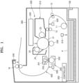
- FIG. 1 is a view illustrating a configuration of an electrophotographic image forming apparatus according to an example.
- a feeder 100 on which a print medium P is loaded, and a discharger 300 on which the print medium P that has been completely printed is loaded are illustrated.
- a print path 400 connects the feeder 100 and the discharger 300.
- An image former 200 is located in the print path 400.
- the print medium P loaded on the feeder 100 is taken out one by one, and is conveyed along the print path 400.
- the feeder 100 is a feed cassette in the present example, the feeder 100 is not limited thereto.
- the feeder 100 may be a multi-purpose feed tray.
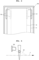
- FIG. 2 is a plan view of the feeder 100.
- the print medium P is loaded in a center alignment method on the feeder 100.
- the feeder 100 may include one pair of guide members 101 and 102.
- the one pair of guide members 101 and 102 guide both end portions of the print medium P in a width direction of the print medium P so that the print medium P is loaded in the center alignment method on the feeder 100.
- the one pair of guide members 101 and 102 may be moved toward/away from each other.
- the one pair of guide members 101 and 102 may be synchronized and may be moved toward/away from each other.
- the one pair of guide members 101 and 102 may be located as indicated by a solid line of FIG. 2 , and in order to load a print medium P2 having a small width, the one pair of guide members 101 and 102 may be located as indicated by a dashed line of FIG. 2 .
- the image former 200 forms an image by using an electrophotographic method on the print medium P that is conveyed along the print path 400.
- the image former 200 may include a developing unit 210, an exposure unit 220, a transfer roller 230, and a fusing unit 240.
- the developing unit 210 supplies toner contained in the developing unit 210 to an electrostatic latent image formed on a photosensitive drum 21 and develops the electrostatic latent image into a visible toner image.
- the photosensitive drum 21 that is a photoconductor on a surface of which the electrostatic latent image is formed may include a conductive metal pipe and a photosensitive layer formed on an outer circumferential surface of the conductive metal pipe.
- a charging roller 22 charges a surface of the photosensitive drum 21 to a uniform potential.
- the exposure unit 220 emits light modulated to correspond to image formation to the photosensitive drum 21 and forms the electrostatic latent image on the photosensitive drum 21.
- a laser scanning unit (LSU) using a laser diode as a light source or a light-emitting diode (LED) exposure unit using an LED as a light source may be used as the exposure unit 220.
- a developing roller 23 supplies a developer, e.g., the toner, contained in the developing unit 210 to the photosensitive drum 21 and develops the electrostatic latent image into the visible toner image.
- a development bias voltage may be applied to the developing roller 23.
- the toner may be contained in the developing unit 210.
- the toner, or the toner and a carrier may be contained in the developing unit 210.
- the developing unit 210 may further include a supply roller configured to supply the developer contained in the developing unit 210 to the developing roller 23, a regulation member configured to regulate the amount of the developer attached to a surface of the developing roller 23 and supplied to a development area where the photosensitive drum 21 and the developing roller 23 face each other, and an agitator configured to agitate the developer contained in the developing unit 210.
- the transfer roller 230 is a transfer unit configured to transfer the toner image from the photosensitive drum 21 to the print medium P.
- a transfer bias voltage for transferring the toner image to the print medium P is applied to the transfer roller 230.
- a coroner transfer unit or a transfer unit using a pin scorotron method may be used, instead of the transfer roller 230.
- the print medium P is picked up one by one from the feeder 100 by a pickup roller 11, and is conveyed to an area where the photosensitive drum 21 and the transfer roller 230 face each other by conveying rollers 12 and 13.
- the fusing unit 240 fixes the toner image transferred to the print medium P onto the print medium P by applying heat and pressure to the toner image.
- the print medium P passing through the fusing unit 240 is discharged to and loaded on the discharger 300 by a discharging roller 19.
- a cleaning blade 24 is a cleaning unit for removing the toner and a foreign material remaining on the surface of the photosensitive drum 21 after a transfer process.
- Another type of cleaning device such as a rotating brush may be used, instead of the cleaning blade 24.
- the exposure unit 220 forms the electrostatic latent image by scanning light modulated to correspond to the image information to the photosensitive drum 21.
- the developing roller 23 forms the visible toner image on the surface of the photosensitive drum 21 by supplying the toner to the electrostatic latent image.
- the print medium P loaded on the feeder 100 is conveyed to the area where the photosensitive drum 21 and the transfer roller 230 face each other by the pickup roller 11 and the conveying rollers 12 and 13, and the toner image is transferred to the print medium P from the photosensitive drum 21 due to the transfer bias voltage applied to the transfer roller 230.
- the toner image is fixed onto the print medium P due to heat and pressure.
- the print medium P that has been completely fixed is discharged by the discharging roller 19 and is loaded on the discharger 300.
- the fusing unit 240 may include a heating member 241 and a pressing member 242 that are engaged with each other and form a fixing nip through which the print medium P passes.
- the heating member 241 may be heated by a heat source 243.
- the heating member 241 may be, for example, a metal roller or an endless belt.
- the heat source 243 may be, for example, a halogen lamp or a ceramic heater.
- a width of the heating member 241 may correspond to a width of the print medium P. While the print medium P passes through the fixing nip, heat of the heating member 241 is transmitted to the print medium P and the toner image. While printing is performed, the entire width of the heating member 241 is heated.
- a surface of the heating member 241 is divided into a contact portion contacting the print medium P2 and a non-contact portion not contacting the print medium P2 in a width direction. Since heat of the non-contact portion of the heating member 241 is not transmitted, a temperature of the non-contact portion may be higher than a temperature of the contact portion. When a plurality of pieces of paper are continuously printed as the print medium P2 having a small width, a temperature of the non-contact area may be much higher than that of the contact portion. A temperature increase of the heating member 241 may adversely affect a lifetime of the fusing unit 240. Also, heat may be transmitted to other members in the image forming apparatus, and may adversely affect a lifetime of the image forming apparatus.
- the controller 500 controls the image former 200 to print an image in one mode selected from different print modes, for example, a first mode and a second mode, according to a width of the print medium P.
- the controller 500 may stop the printing and may output a print error signal according to a feeding state of the print medium P.
- the first mode that is a normal print mode is applied to the print medium P1 having a maximum size that may be loaded on the feeder 100.
- the second mode that is a low-speed print mode is applied to the print medium P2 having a width less than that of the print medium P1.
- the print medium P1 may be an A4 or LTR sheet
- the print medium P2 may be an A5 or B5 sheet.
- the controller 500 may control the image former 200 to print an image at a first process speed in the first mode, and may control the image former 200 to print an image at a second process speed, which is less than the first process speed, in the second mode.
- the process speed that is a speed at which the image former 200 forms an image refers to a linear speed of the photosensitive drum 21 or a feed speed of the print medium P.
- the controller 500 may set an interval between a previous printing operation and a next printing operation as a first interval in the first mode, and a second interval, which is greater than the first interval, in the second mode.
- the first process speed and the second process speed may be the same, or the second process speed may be less than the first process speed.
- the controller 500 detects the width of the print medium P by combining detection signals of two sensors (a first sensor and a second sensor) for detecting the print medium P in an image forming process, and controls the image former 200 to perform printing in one mode selected from among the first mode and the second mode whose print speed is less than that of the first mode according to the detected width of the print medium P.
- the controller 500 may detect a feeding state of the print medium P by combining detection signals of two sensors (the first sensor and the second sensor) for detecting the print medium P in an image forming process and may stop printing and may output a print error signal according to the detected feeding state of the print medium P.
- FIG. 3 is a view of a sensor according to an example.
- the sensor may include an actuator 551 that contacts the print medium P and is rotated, and a sensing unit 552 that is turned on/off by the actuator 551.
- the sensing unit 552 may be a photointerrupter including, for example, a light emitter and a light receiver.
- the actuator 551 when the print medium P is not detected, the actuator 551 is located on a position indicated by a solid line of FIG. 3 , light emitted from the light emitter is received by the light receiver, and the sensing unit 552 is turned off.
- the actuator 551 pushes the actuator 551 and the actuator 551 is pivoted to a position indicated by a dashed line of FIG.
- the actuator 551 is located between the light emitter and the light receiver, light emitted from the light emitter is blocked by the actuator 551 and is not detected by the light receiver, and the sensing unit 552 is turned on.
- the sensing unit 552 may be connected to the controller 500 by an electrical unit (not shown).
- a state of a detection signal of the sensor is an "on state” when the print medium P is detected by the sensor and is an “off state” when the print medium P is not detected.
- FIG. 4 is a plan view illustrating positions of a first sensor and a second sensor. Referring to FIG. 4 , the first print medium P1 to which the first mode is applied and the second print medium P2 to which the second mode is applied are illustrated.
- the second print medium P2 has a width less than a width of the first print medium P1.
- the second print medium P2 is a print medium having a maximum width to which the second mode is applied.
- the first print medium P1 that is center-aligned includes a first end portion P1-1 and a second end portion P1-2 in a width direction.
- a second print medium P2C that is center-aligned includes a first end portion P2C-1 and a second end portion P2C-2 in the width direction.
- a first sensor 561 is located to detect the print medium P in a region S1 between the first end portion P1-1 of the first print medium P1 that is center-aligned and the first end portion P2C-1 of the second print medium P2C that is center-aligned.
- the actuator 551 of the first sensor 561 may be located in the region S1.
- the second print medium P2 may be loaded as the second print medium P2C on the feeder 100 in a center alignment method as shown in FIG. 4 .
- the first print medium P1 and the second print medium P2 may be distinguishably detected by the first sensor 561.
- the controller 500 may recognize that the first print medium P1 is detected.
- the controller 500 may recognize that the second print medium P2 is detected.
- the controller 500 may detect a width of the print medium P and a feeding state of the print medium P according to a detection signal input from the first sensor 561.
- a feeding state of the print medium P may be an abnormal feeding state.
- the second print medium P2 may be loaded on the feeder 100.
- the second print medium P2 may be side-aligned as a second print medium P2R with the first end portion P1-1 of the first print medium P1 as shown in FIG. 4 , or may be side-aligned as a second print medium P2L with the second end portion P1-2 of the first print medium P1 as shown in FIG. 4 .
- the controller 500 may distinguishably detect the first print medium P1 and the second print medium P2 based on the detection signal of the first sensor 561.
- the controller 500 may not distinguishably detect the first print medium P1 and the second print medium P2 based on the detection signal of the first sensor 561.
- a second sensor 562 is additionally used.
- the second sensor 562 is located to detect the print medium P in a region S2 between a second end portion P2R-2 of the second print medium P2 (i.e., the second print medium P2R of FIG. 4 ) that is side-aligned with the first end portion P1-1 of the first print medium P1 that is center-aligned and the second end portion P2C-2 of the second print medium P2 (i.e., the second print medium P2C of FIG. 4 ) that is center-aligned.
- the actuator 551 of the second sensor 562 may be located in the region S2. Since the second sensor 562 is located to detect the print medium P in the region S2, a plurality of sensors that detect the print medium P in an image forming process may perform their own functions and may be each used as the second sensor 562.
- the controller 500 may distinguishably detect the first print medium P1 and the second print medium P2 both when the first print medium P1 and the second print medium P2 are loaded on the feeder 100 in a normal feeding state in a center alignment method and when the second print medium P2 is wrongly loaded in a side alignment method by combining detection signals of the first sensor 561 and the second sensor 562.
- the controller 500 may control the image former 200 by applying one mode selected from among the first mode and the second mode according to a detection result of a width of the print medium P.
- the controller 500 may stop printing and may output a print error signal according to a detection result of a feeding state of the print medium P.
- Table 1 shows a type of the print medium P, a combination of detection signals of the first sensor 561 and the second sensor 562, and a print mode.
- Table 1 Print medium/feeding state First sensor Second sensor Print mode First print medium P1 On On First mode Second print medium P2/P2C Off On Second mode Second print medium P2/P2R On Off Print error Second print medium P2/P2L Off On Second mode
- the controller 500 may control the image former 200 to perform printing in the first mode.
- a detection signal in an off signal is input from the first sensor 561 (in other words, when a detection signal in an on state is not input)
- the controller 500 may control the image former 200 to perform printing in the second mode.
- the controller 500 may recognize a feeding error state and may output a print error signal. Accordingly, a user may be guided to check a load state of the print medium P and a feeding state of the print medium P, and unnecessary printing and overheating of the fusing unit 240 may be prevented.
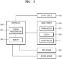
- FIG. 5 is a block diagram of the controller 500 according to an example.
- the controller 500 may include a central processing unit (CPU) 501 and a memory 502.
- First and second control factors respectively corresponding to the first mode and the second mode may be stored in the memory 502.
- the controller 500 may select one mode from among the first and second modes by combining detection signals of the first and second sensors 561 and 562, and may control the image former 200 by reading a corresponding control factor from among the first and second control factors from the memory 502.
- the control factor may be a driving speed of a driving motor 201 that drives rotating members of the image former 200.
- the control factor may be, for example, an operation interval of a clutch 202 that controls driving of the pickup roller 11.
- the image forming apparatus may include a plurality of sensors that detect the print medium P conveyed along the print path 400.
- an additional sensor for detecting a width of the print medium P is not used.
- the controller 500 detects a width of the print medium P by combining detection signals of two sensors from among the plurality of sensors, and controls the image former 200 to perform printing in one mode selected from among the first mode and the second mode whose print speed is less than that of the first mode according to the detected width of the print medium P.
- the controller 500 may detect a feeding state of the print medium P by combining detection signals of two sensors from among the plurality of sensors, and may stop printing and may output a print error signal according to the detected feeding state of the print medium P.
- the image forming apparatus may be made compact.
- the plurality of sensors includes a load detection sensor (e.g., a paper empty sensor) 510 configured to detect whether the print medium P is loaded on the feeder 100, may include an alignment sensor (e.g., a registration sensor) 520 configured to provide a reference position of the print medium P supplied to the image former 200 and a paper jam sensor 530 located at an outlet of the fusing unit 240 and configured to detect a jam on the fusing unit 240, and includes an overload detection sensor 540 provided on the discharger 300 and configured to detect an overload of the discharger 300.
- a load detection sensor e.g., a paper empty sensor
- an alignment sensor e.g., a registration sensor
- a paper jam sensor 530 located at an outlet of the fusing unit 240 and configured to detect a jam on the fusing unit 240
- an overload detection sensor 540 provided on the discharger 300 and configured to detect an overload of the discharger 300.
- Each of the load detection sensor 510, the alignment sensor 520, paper jam sensor 530, and the overload detection sensor 540 may have, for example, a structure as shown in FIG. 3 .
- the load detection sensor 510 is located at a position indicated by a solid line of FIG. 3 when the print medium P is not loaded on the feeder 10, and a detection signal is maintained in an off state.
- the alignment sensor 520 may be located at an inlet of the conveying roller 13. When the print medium P is detected by the alignment sensor 520, the controller 500 recognizes that a front end of the print medium P passes through the alignment sensor 520. Accordingly, a reference position of the print medium P may be provided.
- the controller 500 may control an exposure start time of the exposure unit 220 so that a front end of a toner image formed on the photosensitive drum 21 reaches a transfer nip at a time when the front end of the print medium P reaches the transfer nip where the photosensitive drum 21 and the transfer roller 230 face each other.
- the paper jam sensor 530 is turned on as indicated by a dashed line of FIG. 3 when the print medium P passes. If the paper jam sensor 530 is not turned off even after a predetermined period of time elapses after the paper jam sensor 530 is turned on, the controller 500 may recognize that a jam occurs on the fusing unit 240.
- the overload detection sensor 540 is turned on as indicated by a dashed line of FIG.
- the controller 500 may recognize that the amount of the print medium P loaded on the discharger 300 exceeds a load capacity.
- the first sensor 561 may be the overload detection sensor 540.
- the overload detection sensor 540 is located to detect the print medium P discharged in the region S1 of FIG. 4 in a width direction.
- the second sensor 562 may be selected from among sensors that are provided in the feeder 100 and in the print path 400 between the feeder 100 and the discharger 300 and detect the print medium P.
- the load detection sensor 510, the alignment sensor 520, and the paper jam sensor 530 are illustrated in FIG. 1 , an additional sensor may be further located between the pickup roller 11 and the conveying roller 13.
- any one of the load detection sensor 510, the alignment sensor 520, and the paper jam sensor 530 is used as the second sensor 562.
- Any one of the load detection sensor 510, the alignment sensor 520, and the paper jam sensor 530 is located to detect the print medium P in the region S2 of FIG. 4 in the width direction.
- the plurality of sensors for example, the load detection sensor 510, the alignment sensor 520, and the paper jam sensor 530, may be used as the second sensor 562. Since the load detection sensor 510, the alignment sensor 520, and the paper jam sensor 530 are located in the region S2, the sensors may perform their own functions and may also perform a function of the second sensor 562 that detects a width and a feeding state of the print medium P.
- the controller 500 may control the image former 200 to perform printing in one mode from among the first mode and the second mode by combining detection signals of any one of the load detection sensor 510, the alignment sensor 520, and the paper jam sensor 530 functioning as the second sensor 562 and the overload detection sensor 540 functioning as the first sensor 561 as shown in Table 1. Also, the controller 500 may stop the printing and may output a print error signal according to a combination result of the detection signals. Accordingly, without employing an additional sensor that detects a width of the print medium P, the controller 500 may distinguishably recognize the first print medium P1 and the second print medium P2 (e.g., the second print medium P2C, P2L, or P2R of FIG.
- the first print medium P1 and the second print medium P2 e.g., the second print medium P2C, P2L, or P2R of FIG.
- a print error signal may be output.
- an image is successfully printed on the first print medium P1 and the second print medium P2 loaded as the second print medium P2C, and an image is not successfully printed on the second print medium P2 loaded as the second print medium P2L or the second print medium P2R. That is, only a part of an image to be printed is printed on the second print medium P2 loaded as the second print medium P2L or the second print medium P2R.
- the image forming apparatus is a network printer, the user may not know a load state of the print medium P on the feeder 100.
- the second mode may be applied to the second print medium P2L or the second print medium P2R that is inappropriately loaded on the feeder 100 as well as the second print medium P2 that is appropriately loaded on the feeder 100 as the second print medium P2C, in particular, overheating of the fusing unit 240 may be effectively prevented when a plurality of pieces are continuously printed as the second print medium P2. Also, since a print error signal is output when the second print medium P2 is fed as the second print medium P2R, unnecessary printing and overheating of the fusing unit 240 may be prevented.
- a state of a detection signal of the load detection sensor 510 is an off state in an image forming process, it means that the print medium P is not loaded on the feeder 100, the print medium P loaded on the feeder 100 has been completely used, or the second print medium P2 is loaded as the second print medium P2R. Since normal printing may not be performed in any of the above cases, the controller 500 may stop printing and may output a print error signal. Accordingly, the user may be guided to check a load state of the print medium P. Also, since an image is not appropriately printed on the second print medium P2 loaded as the second print medium P2R, unnecessary printing may be prevented.
- a print error signal may be output through an output device 503 (see FIG. 5 ).
- the output device 503 may be, for example, a buzzer, a display, a lamp, or the user's host device.
- a detection signal of the alignment sensor 520 When a detection signal of the alignment sensor 520 is not changed from an off state to an on state in an image forming process, it means that conveyance failure occurs in the print path 400 from the feeder 100 to the alignment sensor 520 or the second print medium P2 is loaded as the second print medium P2R.
- the controller 500 may drive the image forming apparatus for a time long enough for the print medium P to reach the discharger 300 and may check whether a detection signal in an on state is input from the overload detection sensor 540 during the driving time.
- the controller 500 may stop printing and may output a print error signal.
- a detection signal in an on state is not input from the overload detection sensor 540, it means that conveyance failure occurs. Accordingly, the controller 500 may stop printing and may output a print error signal.
- the print error signal may be output through the output device 503 (see FIG. 5 ).
- the output device 503 may be, for example, a buzzer, a display, a lamp, or the user's host device.
- a detection signal of the paper jam sensor 530 When a detection signal of the paper jam sensor 530 is not changed from an off state to an on state in an image forming process, it means that conveyance failure occurs in the print path 400 from the feeder 100 to the fusing unit 240, or the second print medium P2 is loaded as the second print medium P2R.
- the controller 500 may drive the image forming apparatus for a time long enough for the print medium P to reach the discharger 300, and may check whether a detection signal in an on state is input from the overload detection sensor 540 during the driving time.
- the controller 500 may stop printing and may output a print error signal.
- a detection signal in an on state is not input from the overload detection sensor 540, it means that conveyance failure occurs. Accordingly, the controller 500 may stop printing and may output a print error signal.
- the print error signal may be output through the output device 503 (see FIG. 5 ).
- the output device 503 may be, for example, a buzzer, a display, a lamp, or the user's host device.
Landscapes
- Physics & Mathematics (AREA)
- General Physics & Mathematics (AREA)
- Engineering & Computer Science (AREA)
- Microelectronics & Electronic Packaging (AREA)
- Mechanical Engineering (AREA)
- Controlling Sheets Or Webs (AREA)
- Control Or Security For Electrophotography (AREA)
Claims (9)
- Bilderzeugungsvorrichtung, die umfasst:eine Zuführeinrichtung (100), auf der ein Druckmedium in einem zentralen Ausrichtungsverfahren ladbar ist;einen Bilderzeuger (200), ein Bild durch Verwenden eines elektrofotografischen Verfahrens auf dem Druckmedium, das von dem Bilderzeuger zugeführt wird, zu drucken;einen Entlader (300), auf dem das Druckmedium, das das Bild darauf gedruckt aufweist, entladbar ist;einen Ladungserfassungssensor (510), der sich auf der Zuführeinrichtung befindet, um zu erfassen, ob das Druckmedium auf die Zuführeinrichtung geladen ist;einen Überladungserfassungssensor (540), um eine Überladung des Entladers zu erfassen; undgekennzeichnet durch eine Steuerung (500) zumErfassen einer Breite des Druckmediums gemäß einer Kombination eines Zuführeinrichtungsladungszustands eines Zuführeinrichtungsladungserfassungssignals des Ladungserfassungssensors und eines Überladungszustands eines Entladerüberladungserfassungssignals des Überladungserfassungssensors undSteuern des Bilderzeugers, um ein Drucken durch ein Anwenden unterschiedlicher Druckmodi gemäß der erfassten Breite des Druckmediums durchzuführen.
- Bilderzeugungsvorrichtung nach Anspruch 1, wobei die unterschiedlichen Druckmodi einen ersten Modus und einen zweiten Modus umfassen, wobei der zweite Modus einer zweiten Druckgeschwindigkeit entspricht, die geringer als eine erste Druckgeschwindigkeit ist, die dem ersten Modus entspricht.
- Bilderzeugungseinrichtung nach Anspruch 2, wobei das Druckmedium eines ist voneinem ersten Druckmedium, das eine erste Breite aufweist, auf die der erste Modus anzuwenden ist odereinem zweiten Druckmedium, das eine zweite Breite aufweist, die geringer als die erste Breite des ersten Druckmediums und eine maximale Breite ist, auf die der zweite Modus anzuwenden ist,wobeider Überladungszustand des Entladerüberladungserfassungssignals von dem Überladungserfassungssensor auf der Basis darauf eingegeben wird, dass der Überladungserfassungssensor das Druckmedium zwischen einem ersten Endabschnitt in einer Breitenrichtung des ersten Druckmediums, der zentral ausgerichtet ist, und einem ersten Endabschnitt in einer Breitenrichtung des zweiten Druckmediums, der zentral ausgerichtet ist, erfasst undder Zuführeinrichtungsladungszustand des Zuführeinrichtungsladungserfassungssignals von dem Ladungserfassungssensor auf der Basis darauf eingegeben wird, dass der Ladungserfassungssensor das Druckmedium zwischen einem zweiten Endabschnitt in Breitenrichtung des zweiten Druckmediums, der mit dem ersten Endabschnitt in Breitenrichtung des ersten Druckmediums seitlich ausgerichtet ist, und einem zweiten Endabschnitt in der Breitenrichtung des zweiten Druckmediums, der zentral ausgerichtet ist, erfasst.
- Bilderzeugungsvorrichtung nach Anspruch 3, wobei die Steuerung ferner dient zumErfassen eines Zuführzustands des Druckmediums gemäß einer Kombination des Zuführeinrichtungsladungszustands des Zuführeinrichtungsladungserfassungssignals des Ladungserfassungssensors und des Überladungszustands des Entladerüberladungserfassungssignals des Überladungserfassungssensors undStoppen des Druckens und Ausgeben eines Druckfehlersignals gemäß dem erfassten Zuführzustand des Druckmediums.
- Bilderzeugungsvorrichtung nach Anspruch 4, wobeidie Zuführeinrichtungsladungs- und Überladungszustände der Zuführeinrichtungsladungs- beziehungsweise Entladerüberladungserfassungssignale die Ein- oder Aus-Zustände einschließen undwenn die Zuführeinrichtungsladungs- und Überladungszustände sowohl der Zuführeinrichtungsladungs- als auch der Entladerüberladungserfassungssignale in An-Zuständen von sowohl dem Überladungserfassungssensor als auch dem Ladungserfassungssensor eingegeben werden, die Steuerung dazu dient, den Bilderzeuger zu steuern, um das Drucken in dem ersten Modus durchzuführen.
- Bilderzeugungsvorrichtung nach Anspruch 4, wobeider Überladungszustand des Entladerüberladungserfassungssignals einen Ein- oder Aus-Zustand einschließt undwenn der Überladungszustand des Entladerüberladungserfassungssignals in einem Aus-Zustand von dem Überladungserfassungssensor eingegeben wird, die Steuerung dazu dient, den Bilderzeuger zu steuern, um das Drucken in dem zweiten Modus durchzuführen.
- Bilderzeugungsvorrichtung nach Anspruch 4, wobeider Zuführeinrichtungsladungszustand des Zuführeinrichtungsladungserfassungssignals einen Ein- oder Aus-Zustand einschließt undwenn der Zuführeinrichtungsladungszustand des Zuführeinrichtungsladungserfassungssignals in einem Aus-Zustand von dem Ladungserfassungssensor eingegeben wird, die Steuerung dazu dient, das Drucken zu stoppen und das Druckfehlersignal auszugeben.
- Bilderzeugungsvorrichtung nach einem der Ansprüche 2, wobei die Steuerung dazu dient, den Bilderzeuger zu steuern, das Bild mit der ersten Druckgeschwindigkeit in dem ersten Modus zu drucken und
den Bilderzeuger zu steuern, das Bild mit der zweiten Druckgeschwindigkeit, die geringer als die erste Druckgeschwindigkeit in dem zweiten Modus ist, zu drucken. - Bilderzeugungsvorrichtung nach Anspruch 2, wobei die Steuerung dazu dient, ein Intervall zwischen Druckvorgängen während des kontinuierlichen Drucks als ein erstes Intervall in dem ersten Modus und ein zweites Intervall, das größer als das erste Intervall ist, in dem zweiten Modus einzustellen.
Applications Claiming Priority (2)
| Application Number | Priority Date | Filing Date | Title |
|---|---|---|---|
| KR1020180034769A KR20190112598A (ko) | 2018-03-26 | 2018-03-26 | 인쇄경로에 존재하는 센서들을 이용하여 인쇄매체의 크기를 감지하는 방법 및 기구 |
| PCT/US2019/023658 WO2019190926A1 (en) | 2018-03-26 | 2019-03-22 | Detecting size of print medium using sensors available along paper path |
Publications (3)
| Publication Number | Publication Date |
|---|---|
| EP3746847A1 EP3746847A1 (de) | 2020-12-09 |
| EP3746847A4 EP3746847A4 (de) | 2022-01-26 |
| EP3746847B1 true EP3746847B1 (de) | 2024-01-03 |
Family
ID=68058441
Family Applications (1)
| Application Number | Title | Priority Date | Filing Date |
|---|---|---|---|
| EP19777720.4A Active EP3746847B1 (de) | 2018-03-26 | 2019-03-22 | Erfassung der grösse eines druckmediums unter verwendung von sensoren, die entlang eines papierwegs verfügbar sind |
Country Status (4)
| Country | Link |
|---|---|
| US (1) | US12013656B2 (de) |
| EP (1) | EP3746847B1 (de) |
| KR (1) | KR20190112598A (de) |
| WO (1) | WO2019190926A1 (de) |
Families Citing this family (1)
| Publication number | Priority date | Publication date | Assignee | Title |
|---|---|---|---|---|
| JP7268482B2 (ja) * | 2019-05-24 | 2023-05-08 | 京セラドキュメントソリューションズ株式会社 | シート搬送装置 |
Family Cites Families (21)
| Publication number | Priority date | Publication date | Assignee | Title |
|---|---|---|---|---|
| JPH05105265A (ja) | 1991-10-15 | 1993-04-27 | Fuji Xerox Co Ltd | 用紙サイズ検出装置 |
| JP3130718B2 (ja) | 1993-11-04 | 2001-01-31 | キヤノン株式会社 | 画像形成装置 |
| US6471429B1 (en) * | 1999-01-29 | 2002-10-29 | Canon Kabushiki Kaisha | Sheet processing apparatus for discharging sheets in a bundle |
| JP2001002279A (ja) | 1999-06-18 | 2001-01-09 | Canon Inc | 画像出力装置及びその制御方法 |
| JP2001072304A (ja) * | 1999-09-01 | 2001-03-21 | Canon Inc | 画像形成装置及び画像形成システム |
| US6722646B2 (en) * | 2002-02-19 | 2004-04-20 | Canon Kabushiki Kaisha | Sheet treating apparatus and image forming apparatus |
| US6807383B2 (en) | 2002-07-31 | 2004-10-19 | Riso Kagaku Corporation | Apparatus, system for forming image, and method for controlling image forming apparatus |
| JP2005263402A (ja) | 2004-03-18 | 2005-09-29 | Fuji Xerox Co Ltd | 記録シート検知装置並びにその検知装置を用いた定着装置および画像形成装置 |
| JP4781173B2 (ja) | 2005-06-29 | 2011-09-28 | キヤノン株式会社 | シートサイズ検知装置 |
| JP5153285B2 (ja) * | 2006-10-18 | 2013-02-27 | キヤノン株式会社 | 画像形成装置 |
| JP2011064773A (ja) | 2009-09-15 | 2011-03-31 | Brother Industries Ltd | 画像形成装置 |
| KR101725093B1 (ko) | 2009-12-24 | 2017-04-10 | 에스프린팅솔루션 주식회사 | 화상형성장치 |
| JP6040714B2 (ja) * | 2012-11-06 | 2016-12-07 | 株式会社リコー | 自動原稿搬送装置、自動原稿搬送装置を備えた画像読取装置および画像形成装置 |
| US9274463B2 (en) * | 2013-06-13 | 2016-03-01 | Lexmark International, Inc. | Heat transfer system for a fuser assembly |
| US9310728B2 (en) * | 2013-06-13 | 2016-04-12 | Lexmark International, Inc. | Latch mechanism for a fuser assembly having a heat transfer roll |
| JP6292873B2 (ja) * | 2013-12-27 | 2018-03-14 | キヤノン株式会社 | シート処理装置及び画像形成システム |
| JP6341443B2 (ja) * | 2014-02-25 | 2018-06-13 | 株式会社リコー | シート載置装置、画像形成装置及び画像読取装置 |
| JP6305166B2 (ja) * | 2014-03-31 | 2018-04-04 | キヤノン株式会社 | 印刷装置 |
| JP2017122768A (ja) * | 2016-01-05 | 2017-07-13 | キヤノン株式会社 | 画像形成装置 |
| JP7370750B2 (ja) * | 2019-07-11 | 2023-10-30 | キヤノン株式会社 | 画像形成装置 |
| JP7475865B2 (ja) * | 2020-01-08 | 2024-04-30 | キヤノン株式会社 | 画像処理装置、画像処理装置の制御方法、並びにプログラム |
-
2018
- 2018-03-26 KR KR1020180034769A patent/KR20190112598A/ko not_active Withdrawn
-
2019
- 2019-03-22 EP EP19777720.4A patent/EP3746847B1/de active Active
- 2019-03-22 US US17/040,918 patent/US12013656B2/en active Active
- 2019-03-22 WO PCT/US2019/023658 patent/WO2019190926A1/en not_active Ceased
Also Published As
| Publication number | Publication date |
|---|---|
| EP3746847A1 (de) | 2020-12-09 |
| KR20190112598A (ko) | 2019-10-07 |
| US12013656B2 (en) | 2024-06-18 |
| US20210034005A1 (en) | 2021-02-04 |
| EP3746847A4 (de) | 2022-01-26 |
| WO2019190926A1 (en) | 2019-10-03 |
Similar Documents
| Publication | Publication Date | Title |
|---|---|---|
| US6728497B2 (en) | Image forming apparatus having a heating member to heat the recording medium | |
| KR101725093B1 (ko) | 화상형성장치 | |
| US20170075273A1 (en) | Fixing device and image forming apparatus having the same | |
| JP2014032236A (ja) | 画像形成装置 | |
| RU2649213C1 (ru) | Устройство регистрации температуры и устройство формирования изображения | |
| JP3800118B2 (ja) | 熱定着装置および画像形成装置 | |
| EP3746847B1 (de) | Erfassung der grösse eines druckmediums unter verwendung von sensoren, die entlang eines papierwegs verfügbar sind | |
| US11747755B2 (en) | Image forming apparatus having controller for setting cooling threshold according to sheet size | |
| US8725012B2 (en) | Image forming apparatus and a method for determining a condition of toner | |
| US20220100129A1 (en) | Image forming apparatus and method for controlling image forming apparatus | |
| JP4962437B2 (ja) | 画像形成装置 | |
| JP2007047390A (ja) | 定着装置 | |
| US10884359B2 (en) | Automatic cleaning image forming apparatus and method of controlling image forming apparatus | |
| US10816925B1 (en) | Image forming apparatus having controller to control stabilization process depending on toner amount | |
| JP7135784B2 (ja) | 媒体厚検出装置、媒体搬送装置および画像形成装置 | |
| US20070201890A1 (en) | Fusing system of image forming apparatus and method for controlling thereof | |
| JP7380232B2 (ja) | 定着装置、画像形成装置 | |
| JP7183755B2 (ja) | 画像形成装置 | |
| KR100555720B1 (ko) | 전자사진방식 화상형성장치 및 그의 정착장치 제어방법 | |
| JP4501831B2 (ja) | 画像形成装置 | |
| JP6331417B2 (ja) | 画像形成装置 | |
| JP2025029477A (ja) | 画像形成装置、画像形成装置の制御方法及びプログラム | |
| JP2025158513A (ja) | 検知装置、画像形成装置 | |
| JP2016175718A (ja) | 媒体搬送装置および画像形成装置 | |
| JP2002162805A (ja) | 画像形成装置 |
Legal Events
| Date | Code | Title | Description |
|---|---|---|---|
| STAA | Information on the status of an ep patent application or granted ep patent |
Free format text: STATUS: THE INTERNATIONAL PUBLICATION HAS BEEN MADE |
|
| PUAI | Public reference made under article 153(3) epc to a published international application that has entered the european phase |
Free format text: ORIGINAL CODE: 0009012 |
|
| STAA | Information on the status of an ep patent application or granted ep patent |
Free format text: STATUS: REQUEST FOR EXAMINATION WAS MADE |
|
| 17P | Request for examination filed |
Effective date: 20200904 |
|
| AK | Designated contracting states |
Kind code of ref document: A1 Designated state(s): AL AT BE BG CH CY CZ DE DK EE ES FI FR GB GR HR HU IE IS IT LI LT LU LV MC MK MT NL NO PL PT RO RS SE SI SK SM TR |
|
| AX | Request for extension of the european patent |
Extension state: BA ME |
|
| DAV | Request for validation of the european patent (deleted) | ||
| DAX | Request for extension of the european patent (deleted) | ||
| REG | Reference to a national code |
Ref country code: DE Ref legal event code: R079 Free format text: PREVIOUS MAIN CLASS: G03G0021140000 Ipc: G03G0015000000 Ref document number: 602019044490 Country of ref document: DE |
|
| A4 | Supplementary search report drawn up and despatched |
Effective date: 20220107 |
|
| RIC1 | Information provided on ipc code assigned before grant |
Ipc: B65H 7/02 20060101ALI20211223BHEP Ipc: G03G 15/00 20060101AFI20211223BHEP |
|
| GRAP | Despatch of communication of intention to grant a patent |
Free format text: ORIGINAL CODE: EPIDOSNIGR1 |
|
| STAA | Information on the status of an ep patent application or granted ep patent |
Free format text: STATUS: GRANT OF PATENT IS INTENDED |
|
| INTG | Intention to grant announced |
Effective date: 20231006 |
|
| GRAS | Grant fee paid |
Free format text: ORIGINAL CODE: EPIDOSNIGR3 |
|
| GRAA | (expected) grant |
Free format text: ORIGINAL CODE: 0009210 |
|
| STAA | Information on the status of an ep patent application or granted ep patent |
Free format text: STATUS: THE PATENT HAS BEEN GRANTED |
|
| AK | Designated contracting states |
Kind code of ref document: B1 Designated state(s): AL AT BE BG CH CY CZ DE DK EE ES FI FR GB GR HR HU IE IS IT LI LT LU LV MC MK MT NL NO PL PT RO RS SE SI SK SM TR |
|
| REG | Reference to a national code |
Ref country code: GB Ref legal event code: FG4D |
|
| REG | Reference to a national code |
Ref country code: DE Ref legal event code: R096 Ref document number: 602019044490 Country of ref document: DE |
|
| REG | Reference to a national code |
Ref country code: CH Ref legal event code: EP |
|
| REG | Reference to a national code |
Ref country code: IE Ref legal event code: FG4D |
|
| REG | Reference to a national code |
Ref country code: NL Ref legal event code: FP |
|
| PGFP | Annual fee paid to national office [announced via postgrant information from national office to epo] |
Ref country code: NL Payment date: 20240220 Year of fee payment: 6 |
|
| REG | Reference to a national code |
Ref country code: LT Ref legal event code: MG9D |
|
| PG25 | Lapsed in a contracting state [announced via postgrant information from national office to epo] |
Ref country code: ES Free format text: LAPSE BECAUSE OF FAILURE TO SUBMIT A TRANSLATION OF THE DESCRIPTION OR TO PAY THE FEE WITHIN THE PRESCRIBED TIME-LIMIT Effective date: 20240103 |
|
| PG25 | Lapsed in a contracting state [announced via postgrant information from national office to epo] |
Ref country code: ES Free format text: LAPSE BECAUSE OF FAILURE TO SUBMIT A TRANSLATION OF THE DESCRIPTION OR TO PAY THE FEE WITHIN THE PRESCRIBED TIME-LIMIT Effective date: 20240103 |
|
| PGFP | Annual fee paid to national office [announced via postgrant information from national office to epo] |
Ref country code: FR Payment date: 20240221 Year of fee payment: 6 |
|
| REG | Reference to a national code |
Ref country code: AT Ref legal event code: MK05 Ref document number: 1647425 Country of ref document: AT Kind code of ref document: T Effective date: 20240103 |
|
| PG25 | Lapsed in a contracting state [announced via postgrant information from national office to epo] |
Ref country code: IS Free format text: LAPSE BECAUSE OF FAILURE TO SUBMIT A TRANSLATION OF THE DESCRIPTION OR TO PAY THE FEE WITHIN THE PRESCRIBED TIME-LIMIT Effective date: 20240503 |
|
| PG25 | Lapsed in a contracting state [announced via postgrant information from national office to epo] |
Ref country code: LT Free format text: LAPSE BECAUSE OF FAILURE TO SUBMIT A TRANSLATION OF THE DESCRIPTION OR TO PAY THE FEE WITHIN THE PRESCRIBED TIME-LIMIT Effective date: 20240103 |
|
| PG25 | Lapsed in a contracting state [announced via postgrant information from national office to epo] |
Ref country code: GR Free format text: LAPSE BECAUSE OF FAILURE TO SUBMIT A TRANSLATION OF THE DESCRIPTION OR TO PAY THE FEE WITHIN THE PRESCRIBED TIME-LIMIT Effective date: 20240404 |
|
| PG25 | Lapsed in a contracting state [announced via postgrant information from national office to epo] |
Ref country code: RS Free format text: LAPSE BECAUSE OF FAILURE TO SUBMIT A TRANSLATION OF THE DESCRIPTION OR TO PAY THE FEE WITHIN THE PRESCRIBED TIME-LIMIT Effective date: 20240403 Ref country code: HR Free format text: LAPSE BECAUSE OF FAILURE TO SUBMIT A TRANSLATION OF THE DESCRIPTION OR TO PAY THE FEE WITHIN THE PRESCRIBED TIME-LIMIT Effective date: 20240103 |
|
| PG25 | Lapsed in a contracting state [announced via postgrant information from national office to epo] |
Ref country code: CZ Free format text: LAPSE BECAUSE OF FAILURE TO SUBMIT A TRANSLATION OF THE DESCRIPTION OR TO PAY THE FEE WITHIN THE PRESCRIBED TIME-LIMIT Effective date: 20240103 Ref country code: AT Free format text: LAPSE BECAUSE OF FAILURE TO SUBMIT A TRANSLATION OF THE DESCRIPTION OR TO PAY THE FEE WITHIN THE PRESCRIBED TIME-LIMIT Effective date: 20240103 |
|
| PG25 | Lapsed in a contracting state [announced via postgrant information from national office to epo] |
Ref country code: RS Free format text: LAPSE BECAUSE OF FAILURE TO SUBMIT A TRANSLATION OF THE DESCRIPTION OR TO PAY THE FEE WITHIN THE PRESCRIBED TIME-LIMIT Effective date: 20240403 Ref country code: NO Free format text: LAPSE BECAUSE OF FAILURE TO SUBMIT A TRANSLATION OF THE DESCRIPTION OR TO PAY THE FEE WITHIN THE PRESCRIBED TIME-LIMIT Effective date: 20240403 Ref country code: LT Free format text: LAPSE BECAUSE OF FAILURE TO SUBMIT A TRANSLATION OF THE DESCRIPTION OR TO PAY THE FEE WITHIN THE PRESCRIBED TIME-LIMIT Effective date: 20240103 Ref country code: IS Free format text: LAPSE BECAUSE OF FAILURE TO SUBMIT A TRANSLATION OF THE DESCRIPTION OR TO PAY THE FEE WITHIN THE PRESCRIBED TIME-LIMIT Effective date: 20240503 Ref country code: HR Free format text: LAPSE BECAUSE OF FAILURE TO SUBMIT A TRANSLATION OF THE DESCRIPTION OR TO PAY THE FEE WITHIN THE PRESCRIBED TIME-LIMIT Effective date: 20240103 Ref country code: GR Free format text: LAPSE BECAUSE OF FAILURE TO SUBMIT A TRANSLATION OF THE DESCRIPTION OR TO PAY THE FEE WITHIN THE PRESCRIBED TIME-LIMIT Effective date: 20240404 Ref country code: CZ Free format text: LAPSE BECAUSE OF FAILURE TO SUBMIT A TRANSLATION OF THE DESCRIPTION OR TO PAY THE FEE WITHIN THE PRESCRIBED TIME-LIMIT Effective date: 20240103 Ref country code: BG Free format text: LAPSE BECAUSE OF FAILURE TO SUBMIT A TRANSLATION OF THE DESCRIPTION OR TO PAY THE FEE WITHIN THE PRESCRIBED TIME-LIMIT Effective date: 20240103 Ref country code: AT Free format text: LAPSE BECAUSE OF FAILURE TO SUBMIT A TRANSLATION OF THE DESCRIPTION OR TO PAY THE FEE WITHIN THE PRESCRIBED TIME-LIMIT Effective date: 20240103 |
|
| PG25 | Lapsed in a contracting state [announced via postgrant information from national office to epo] |
Ref country code: PL Free format text: LAPSE BECAUSE OF FAILURE TO SUBMIT A TRANSLATION OF THE DESCRIPTION OR TO PAY THE FEE WITHIN THE PRESCRIBED TIME-LIMIT Effective date: 20240103 Ref country code: PT Free format text: LAPSE BECAUSE OF FAILURE TO SUBMIT A TRANSLATION OF THE DESCRIPTION OR TO PAY THE FEE WITHIN THE PRESCRIBED TIME-LIMIT Effective date: 20240503 |
|
| PG25 | Lapsed in a contracting state [announced via postgrant information from national office to epo] |
Ref country code: SE Free format text: LAPSE BECAUSE OF FAILURE TO SUBMIT A TRANSLATION OF THE DESCRIPTION OR TO PAY THE FEE WITHIN THE PRESCRIBED TIME-LIMIT Effective date: 20240103 Ref country code: PT Free format text: LAPSE BECAUSE OF FAILURE TO SUBMIT A TRANSLATION OF THE DESCRIPTION OR TO PAY THE FEE WITHIN THE PRESCRIBED TIME-LIMIT Effective date: 20240503 Ref country code: PL Free format text: LAPSE BECAUSE OF FAILURE TO SUBMIT A TRANSLATION OF THE DESCRIPTION OR TO PAY THE FEE WITHIN THE PRESCRIBED TIME-LIMIT Effective date: 20240103 Ref country code: LV Free format text: LAPSE BECAUSE OF FAILURE TO SUBMIT A TRANSLATION OF THE DESCRIPTION OR TO PAY THE FEE WITHIN THE PRESCRIBED TIME-LIMIT Effective date: 20240103 |
|
| REG | Reference to a national code |
Ref country code: DE Ref legal event code: R097 Ref document number: 602019044490 Country of ref document: DE |
|
| PG25 | Lapsed in a contracting state [announced via postgrant information from national office to epo] |
Ref country code: DK Free format text: LAPSE BECAUSE OF FAILURE TO SUBMIT A TRANSLATION OF THE DESCRIPTION OR TO PAY THE FEE WITHIN THE PRESCRIBED TIME-LIMIT Effective date: 20240103 |
|
| PG25 | Lapsed in a contracting state [announced via postgrant information from national office to epo] |
Ref country code: SM Free format text: LAPSE BECAUSE OF FAILURE TO SUBMIT A TRANSLATION OF THE DESCRIPTION OR TO PAY THE FEE WITHIN THE PRESCRIBED TIME-LIMIT Effective date: 20240103 |
|
| PG25 | Lapsed in a contracting state [announced via postgrant information from national office to epo] |
Ref country code: EE Free format text: LAPSE BECAUSE OF FAILURE TO SUBMIT A TRANSLATION OF THE DESCRIPTION OR TO PAY THE FEE WITHIN THE PRESCRIBED TIME-LIMIT Effective date: 20240103 |
|
| PG25 | Lapsed in a contracting state [announced via postgrant information from national office to epo] |
Ref country code: SK Free format text: LAPSE BECAUSE OF FAILURE TO SUBMIT A TRANSLATION OF THE DESCRIPTION OR TO PAY THE FEE WITHIN THE PRESCRIBED TIME-LIMIT Effective date: 20240103 |
|
| PG25 | Lapsed in a contracting state [announced via postgrant information from national office to epo] |
Ref country code: SM Free format text: LAPSE BECAUSE OF FAILURE TO SUBMIT A TRANSLATION OF THE DESCRIPTION OR TO PAY THE FEE WITHIN THE PRESCRIBED TIME-LIMIT Effective date: 20240103 Ref country code: SK Free format text: LAPSE BECAUSE OF FAILURE TO SUBMIT A TRANSLATION OF THE DESCRIPTION OR TO PAY THE FEE WITHIN THE PRESCRIBED TIME-LIMIT Effective date: 20240103 Ref country code: RO Free format text: LAPSE BECAUSE OF FAILURE TO SUBMIT A TRANSLATION OF THE DESCRIPTION OR TO PAY THE FEE WITHIN THE PRESCRIBED TIME-LIMIT Effective date: 20240103 Ref country code: EE Free format text: LAPSE BECAUSE OF FAILURE TO SUBMIT A TRANSLATION OF THE DESCRIPTION OR TO PAY THE FEE WITHIN THE PRESCRIBED TIME-LIMIT Effective date: 20240103 Ref country code: DK Free format text: LAPSE BECAUSE OF FAILURE TO SUBMIT A TRANSLATION OF THE DESCRIPTION OR TO PAY THE FEE WITHIN THE PRESCRIBED TIME-LIMIT Effective date: 20240103 |
|
| REG | Reference to a national code |
Ref country code: CH Ref legal event code: PL |
|
| PLBE | No opposition filed within time limit |
Free format text: ORIGINAL CODE: 0009261 |
|
| STAA | Information on the status of an ep patent application or granted ep patent |
Free format text: STATUS: NO OPPOSITION FILED WITHIN TIME LIMIT |
|
| PG25 | Lapsed in a contracting state [announced via postgrant information from national office to epo] |
Ref country code: LU Free format text: LAPSE BECAUSE OF NON-PAYMENT OF DUE FEES Effective date: 20240322 |
|
| PG25 | Lapsed in a contracting state [announced via postgrant information from national office to epo] |
Ref country code: MC Free format text: LAPSE BECAUSE OF FAILURE TO SUBMIT A TRANSLATION OF THE DESCRIPTION OR TO PAY THE FEE WITHIN THE PRESCRIBED TIME-LIMIT Effective date: 20240103 |
|
| PG25 | Lapsed in a contracting state [announced via postgrant information from national office to epo] |
Ref country code: MC Free format text: LAPSE BECAUSE OF FAILURE TO SUBMIT A TRANSLATION OF THE DESCRIPTION OR TO PAY THE FEE WITHIN THE PRESCRIBED TIME-LIMIT Effective date: 20240103 Ref country code: LU Free format text: LAPSE BECAUSE OF NON-PAYMENT OF DUE FEES Effective date: 20240322 |
|
| PG25 | Lapsed in a contracting state [announced via postgrant information from national office to epo] |
Ref country code: IT Free format text: LAPSE BECAUSE OF FAILURE TO SUBMIT A TRANSLATION OF THE DESCRIPTION OR TO PAY THE FEE WITHIN THE PRESCRIBED TIME-LIMIT Effective date: 20240103 |
|
| 26N | No opposition filed |
Effective date: 20241007 |
|
| REG | Reference to a national code |
Ref country code: BE Ref legal event code: MM Effective date: 20240331 |
|
| GBPC | Gb: european patent ceased through non-payment of renewal fee |
Effective date: 20240403 |
|
| PG25 | Lapsed in a contracting state [announced via postgrant information from national office to epo] |
Ref country code: IT Free format text: LAPSE BECAUSE OF FAILURE TO SUBMIT A TRANSLATION OF THE DESCRIPTION OR TO PAY THE FEE WITHIN THE PRESCRIBED TIME-LIMIT Effective date: 20240103 |
|
| PG25 | Lapsed in a contracting state [announced via postgrant information from national office to epo] |
Ref country code: BE Free format text: LAPSE BECAUSE OF NON-PAYMENT OF DUE FEES Effective date: 20240331 |
|
| PG25 | Lapsed in a contracting state [announced via postgrant information from national office to epo] |
Ref country code: GB Free format text: LAPSE BECAUSE OF NON-PAYMENT OF DUE FEES Effective date: 20240403 |
|
| PG25 | Lapsed in a contracting state [announced via postgrant information from national office to epo] |
Ref country code: IE Free format text: LAPSE BECAUSE OF NON-PAYMENT OF DUE FEES Effective date: 20240322 |
|
| PG25 | Lapsed in a contracting state [announced via postgrant information from national office to epo] |
Ref country code: IE Free format text: LAPSE BECAUSE OF NON-PAYMENT OF DUE FEES Effective date: 20240322 Ref country code: GB Free format text: LAPSE BECAUSE OF NON-PAYMENT OF DUE FEES Effective date: 20240403 Ref country code: BE Free format text: LAPSE BECAUSE OF NON-PAYMENT OF DUE FEES Effective date: 20240331 Ref country code: CH Free format text: LAPSE BECAUSE OF NON-PAYMENT OF DUE FEES Effective date: 20240331 |
|
| PGFP | Annual fee paid to national office [announced via postgrant information from national office to epo] |
Ref country code: DE Payment date: 20250218 Year of fee payment: 7 |
|
| PG25 | Lapsed in a contracting state [announced via postgrant information from national office to epo] |
Ref country code: SI Free format text: LAPSE BECAUSE OF FAILURE TO SUBMIT A TRANSLATION OF THE DESCRIPTION OR TO PAY THE FEE WITHIN THE PRESCRIBED TIME-LIMIT Effective date: 20240103 |
|
| PG25 | Lapsed in a contracting state [announced via postgrant information from national office to epo] |
Ref country code: CY Free format text: LAPSE BECAUSE OF FAILURE TO SUBMIT A TRANSLATION OF THE DESCRIPTION OR TO PAY THE FEE WITHIN THE PRESCRIBED TIME-LIMIT; INVALID AB INITIO Effective date: 20190322 |
|
| PG25 | Lapsed in a contracting state [announced via postgrant information from national office to epo] |
Ref country code: HU Free format text: LAPSE BECAUSE OF FAILURE TO SUBMIT A TRANSLATION OF THE DESCRIPTION OR TO PAY THE FEE WITHIN THE PRESCRIBED TIME-LIMIT; INVALID AB INITIO Effective date: 20190322 |
|
| PG25 | Lapsed in a contracting state [announced via postgrant information from national office to epo] |
Ref country code: FI Free format text: LAPSE BECAUSE OF FAILURE TO SUBMIT A TRANSLATION OF THE DESCRIPTION OR TO PAY THE FEE WITHIN THE PRESCRIBED TIME-LIMIT Effective date: 20240103 |
|
| REG | Reference to a national code |
Ref country code: NL Ref legal event code: MM Effective date: 20250401 |
|
| PG25 | Lapsed in a contracting state [announced via postgrant information from national office to epo] |
Ref country code: TR Free format text: LAPSE BECAUSE OF FAILURE TO SUBMIT A TRANSLATION OF THE DESCRIPTION OR TO PAY THE FEE WITHIN THE PRESCRIBED TIME-LIMIT Effective date: 20240103 |
|
| PG25 | Lapsed in a contracting state [announced via postgrant information from national office to epo] |
Ref country code: NL Free format text: LAPSE BECAUSE OF NON-PAYMENT OF DUE FEES Effective date: 20250401 |
|
| PG25 | Lapsed in a contracting state [announced via postgrant information from national office to epo] |
Ref country code: FR Free format text: LAPSE BECAUSE OF NON-PAYMENT OF DUE FEES Effective date: 20250331 |