EP3735580B1 - Auswerteanordnung für einen thermischen gassensor, verfahren und computerprogramme - Google Patents
Auswerteanordnung für einen thermischen gassensor, verfahren und computerprogramme Download PDFInfo
- Publication number
- EP3735580B1 EP3735580B1 EP19700107.6A EP19700107A EP3735580B1 EP 3735580 B1 EP3735580 B1 EP 3735580B1 EP 19700107 A EP19700107 A EP 19700107A EP 3735580 B1 EP3735580 B1 EP 3735580B1
- Authority
- EP
- European Patent Office
- Prior art keywords
- information
- signal
- detector
- heater
- gas
- Prior art date
- Legal status (The legal status is an assumption and is not a legal conclusion. Google has not performed a legal analysis and makes no representation as to the accuracy of the status listed.)
- Active
Links
Images


Classifications
-
- G—PHYSICS
- G01—MEASURING; TESTING
- G01N—INVESTIGATING OR ANALYSING MATERIALS BY DETERMINING THEIR CHEMICAL OR PHYSICAL PROPERTIES
- G01N25/00—Investigating or analyzing materials by the use of thermal means
- G01N25/18—Investigating or analyzing materials by the use of thermal means by investigating thermal conductivity
-
- G—PHYSICS
- G01—MEASURING; TESTING
- G01F—MEASURING VOLUME, VOLUME FLOW, MASS FLOW OR LIQUID LEVEL; METERING BY VOLUME
- G01F1/00—Measuring the volume flow or mass flow of fluid or fluent solid material wherein the fluid passes through a meter in a continuous flow
- G01F1/68—Measuring the volume flow or mass flow of fluid or fluent solid material wherein the fluid passes through a meter in a continuous flow by using thermal effects
- G01F1/684—Structural arrangements; Mounting of elements, e.g. in relation to fluid flow
- G01F1/688—Structural arrangements; Mounting of elements, e.g. in relation to fluid flow using a particular type of heating, cooling or sensing element
- G01F1/6888—Thermoelectric elements, e.g. thermocouples, thermopiles
-
- G—PHYSICS
- G01—MEASURING; TESTING
- G01N—INVESTIGATING OR ANALYSING MATERIALS BY DETERMINING THEIR CHEMICAL OR PHYSICAL PROPERTIES
- G01N33/00—Investigating or analysing materials by specific methods not covered by groups G01N1/00 - G01N31/00
- G01N33/48—Biological material, e.g. blood, urine; Haemocytometers
- G01N33/483—Physical analysis of biological material
- G01N33/497—Physical analysis of biological material of gaseous biological material, e.g. breath
Definitions
- Embodiments according to the invention relate to evaluation arrangements for a thermal gas sensor, methods and computer programs.
- Gases can currently be analyzed for their properties using a wide variety of sensors.
- various systems for patient ventilation on the market today are differentiated according to use in the clinical and in the home care area (e.g. systems from the companies Heinen+Löwenstein, Dräger and Stephan Medizintechnik).
- Only the top versions of the systems from these providers contain all the necessary measuring devices for determining pressure, respiratory flow and respiratory gas analysis. To do this, several devices must be combined, which mainly measure away from the patient.
- One embodiment relates to an evaluation arrangement for a thermal gas sensor with at least one heater (eg a heating element) and at least one detector (e.g. a thermal chain structure or "thermopile structure", temperature variable resistors or thermistors).
- the evaluation arrangement is z. B. designed to provide information about an amplitude of a detector signal of a first detector (e.g. D1.Uss) and information about a first phase difference between a heater signal and the detector signal of the first detector (e.g. (D1-Hz). phi) to get.
- the evaluation arrangement can also be designed to form a combination signal as an intermediate variable depending on the information about the amplitude of the detector signal (e.g.
- the evaluation arrangement is also designed to B. to determine information about a gas concentration or information about a thermal conductivity of a fluid (e.g. a gas or gas mixture) based on the combination signal (e.g. without considering the individual pieces of information flowing into the combination signal separately again as the calculations progress).
- a fluid e.g. a gas or gas mixture
- the heater and the at least one detector can be exchanged cyclically in order to minimize any (synchronization) errors.
- the detector can act as a heater and the heater as a detector and at a second point in time the detector can act as a detector and the heater as a heater.
- the evaluation arrangement includes two detectors, these two detectors being at the same distance from the heater.
- a sum of the information about the amplitudes of the two detector signals e.g. D1.Uss and D2.Uss
- a sum of the information about the two phase differences ((D1-Hz) .phi and (D2-Hz).phi) of the two detectors.
- One embodiment relates to an evaluation arrangement for a thermal gas sensor with at least one heater (e.g. a heating element) and two detectors arranged at different distances from the heater (e.g. a first thermocouple structure and a second thermocouple structure or temperature-variable resistors or thermistors), the evaluation arrangement being designed to provide information about an amplitude of a detector signal from a first detector (e.g. D1.Uss), information about an amplitude of a detector signal from a second detector (e.g. D2.Uss), information about a first phase difference between a heater signal and the detector signal of the first detector (e.g.
- the evaluation arrangement can be designed as an intermediate variable depending on the information about the amplitudes of the detector signals (e.g. D1.Uss of the first detector and D2.Uss of the second detector) and depending on the information about the first phase difference and depending on the Information about the second phase difference to form a combination signal that can summarize amplitude information and phase information.
- the evaluation arrangement is also designed to determine information about a gas concentration or information about a thermal conductivity of a fluid (e.g. a gas or gas mixture) based on the combination signal (e.g. without further processing of the calculations, the individual information flowing into the combination signal yet to be considered separately).
- gas can be arranged in the thermal gas sensor between the at least one heater and the detectors arranged at different distances or at equal distances (e.g. symmetrically) from the heater, which gas can be analyzed with the evaluation arrangement in cooperation with the thermal gas sensor can.
- heat is transported from the at least one heater to the first detector and the second detector via the gas or gas mixture located between them.
- a detector signal detected by the first detector or a detector signal detected by the second detector can indicate the heat transported from the heater to the respective detector. If a heating signal amplitude (e.g. heater amplitude) of the at least one heater varies (e.g.
- the detector signal from the first detector or the second detector can be sent to the evaluation arrangement.
- the evaluation arrangement can thus receive the respective information about the amplitude from the detector signal of the first detector and from the detector signal of the second detector, as well as information about the first phase difference between the heater signal and the detector signal of the first detector and the information about the second phase difference between the Get heater signal and the detector signal of the second detector.
- the evaluation arrangement can, for example, receive the heater signal from the thermal gas sensor in addition to the detector signals of the first detector or the second detector.
- the evaluation arrangement can, for example, receive the information about the amplitude directly from the thermal gas sensor of the detector signal of the first detector, the information about the amplitude of the detector signal of the second detector, the information about the first phase difference and the information about the second phase difference.
- This exemplary embodiment of the evaluation arrangement is based on the finding that the combination signal, based on the information about the amplitudes of the detector signals and depending on the information about the first phase difference and the information about the second phase difference, represents a very stable signal that is very can be further processed quickly, for example to determine a gas concentration or information about a thermal conductivity of the fluid.
- the evaluation arrangement thus allows rapid gas analysis.
- the evaluation arrangement can be designed to obtain information about a heater amplitude.
- the evaluation arrangement can also be designed to form a linear combination of the information about the heater amplitude, the information about amplitudes of the detector signals, the information about the first phase difference and the information about the second phase difference in order to determine the combination signal (sigX).
- the information about the heater amplitude can be information about a heating power, for example.
- the information about a heater amplitude can also be referred to as Hz.Uss.
- the evaluation arrangement can, for example, receive the information about the heater amplitude directly from the thermal gas sensor or, for example, from a heater signal sent by the thermal gas sensor to the evaluation arrangement.
- the linear combination can have, for example, a first term that has a first linear combination of the information about the heater amplitude and the information about amplitudes of the detector signals, and a second term that has a second linear combination of the information about the first phase difference and the information about the second has phase difference.
- the first term and the second term can be weighted with different constants in the linear combination in order to determine the combination signal. Since the evaluation arrangement takes the heater amplitude into account when determining the combination signal, the heater signal (e.g.
- a signal of periodic temperature waves emitted by the heater can be compared with the detector signal of the first detector or the second detector (e.g a received signal of periodic temperature waves) can be compared, whereby a heat transfer from the heater via the gas to be analyzed to the two detectors can be determined very accurately can. A very precise and rapid gas analysis is thus made possible with the evaluation arrangement.
- sigUss can be amplitude information or an amplitude signal that can be dependent on the information about the amplitude of the detector signal of the first detector and on the information about the amplitude of the detector signal of the second detector.
- the sigPhi term may be phase information or an added phase signal, which may depend on the first phase difference information and on the second phase difference information, and the factors Ka and Kp may be constants.
- Ka and Kp can weight the amplitude information or the phase information separately, so that the evaluation arrangement can receive the combination signal sigX.
- the amplitude information sigUss can be a linear combination of the information about the amplitude of the detector signal of the first detector and the information about the amplitude of the detector signal of the second detector.
- the phase information sigPhi can be a linear combination of the information about the first phase difference and the information about the second phase difference.
- the constants Ka and Kp can represent conversion factors, for example.
- Ka and Kp are weighting factors for an optimized combination signal, with the factors Ka and Kp being able to represent variables without units (for an embedded system such as that used here, which supplies a CO2 concentration, for example, this is not necessary, for example).
- a conversion to amplitude and time/angle is thus e.g. B. given by the technical data of a circuit and the embedded system ( ⁇ Controller) of the evaluation arrangement.
- the factors are e.g. B. selected so that over the measuring range of the CO2 calibration, both signal components (amplitude and phase) are included in the combination signal SigX in approximately equal proportions, so that e.g. B. the largest measurement resolution is obtained in SigX.
- the factors Ka and Kp are e.g. B. empirically determined to z. B. to get the best signal for SigX.
- the constants Ka and Kp can, for example, depend on a concentration, a Temperature or pressure of a gas to be analyzed.
- the amplitude information sigUss can thus be matched to the phase information sigPhi. It is made possible for the evaluation arrangement to be able to further process both amplitude information and phase information with the combination signal in one go, as a result of which, for example, the evaluation arrangement can analyze the gas detected by the gas sensor very quickly, efficiently and precisely.
- the Hz.Uss term can be information about a heater amplitude
- the term D1.Uss can be the information about the amplitude of the detector signal of the first detector
- D2.Uss can be the information about the amplitude of the detector signal of the second detector.
- the amplitude information sigUss can thus represent a relative amplitude signal.
- the amplitude information can be a difference between twice the heater amplitude and a sum of the information about the amplitude of the detector signal of the first detector and the information about the amplitude of the detector signal of the second detector.
- This special calculation of the amplitude information sigUss can ensure that the amplitude information sigUss depends essentially on heat transfer through the fluid and unknown heat transfers, for example from the at least one heater into the gas to be analyzed and from the gas to be analyzed into the first or second Detector are not or only rarely taken into account.
- the combination signal sigX which may depend on the amplitude information sigUss, e.g. B. not or only slightly affected by unknown heat transfer, whereby the evaluation very precisely properties of the gas to be analyzed, such. B can determine the information about the gas concentration or the information about the thermal conductivity of the fluid.
- the evaluation arrangement can be designed to calculate a polynomial (for example first degree, for example Ay(sigX)) of the combination signal in order to obtain information about the gas concentration or information about the thermal conductivity of the fluid.
- a drift correction of the combination signal can be carried out by the polynomial formation of the evaluation arrangement of the combination signal. For example, concentration drift, pressure drift and temperature drift can be corrected by forming polynomials.
- the evaluation arrangement can calculate three polynomials of the combination signal, where a first polynomial can represent a relationship between the gas concentration and the combination signal, a second polynomial can represent a relationship between pressure and signal shift (pressure drift of the combination signal) and a third polynomial can represent a relationship between a temperature and pressure shift can.
- a first polynomial can represent a relationship between the gas concentration and the combination signal
- a second polynomial can represent a relationship between pressure and signal shift (pressure drift of the combination signal)
- a third polynomial can represent a relationship between a temperature and pressure shift can.
- the evaluation arrangement can be designed to multiply a polynomial of the combination signal by a correction term in order to obtain information about the gas concentration or information about the thermal conductivity.
- the correction term can be dependent on the combination signal, information about a pressure (p) and information about a temperature (T).
- the correction term can thus, for example, compensate for a pressure and temperature dependency of the combination signal.
- a polynomial that represents a relationship between a gas concentration and the combination signal can be corrected for a pressure and temperature drift using the correction term.
- the evaluation arrangement can reduce possible error effects, as a result of which the evaluation arrangement can be designed to obtain very precise information about the gas concentration or information about the thermal conductivity. In this way, for example, pressure- and temperature-dependent errors that arise, for example, when a detector signal is detected by the first detector or the second detector of the gas sensor, can be minimized.
- sigX can be the combination signal
- pol(sigX) can be a polynomial of the combination signal sigX
- f(p) can be a function of the pressure p (or a measured pressure p in an environment of the thermal gas sensor)
- const1 can be a first constant
- f(T) can be a function of temperature T (or a measured temperature T in an environment of the thermal gas sensor)
- const2 can be a second constant.
- the function f(p) can be a polynomial, for example, which can represent a relationship between a pressure and a signal shift and f(T) can be a A polynomial that can represent a relationship between a temperature and a signal shift.
- the term sigX can be the combination signal, Ay(sigX) can be a polynomial (e.g.
- By(p) can be a function of the pressure p (or a measured pressure p in an environment of the thermal gas sensor)
- B.ref can be a constant
- Cy(T) can be a function of the temperature T (or a measured temperature T in an environment of the thermal gas sensor)
- C.ref can be a second constant.
- By(p) is, for example, a polynomial function (for example of the second order) which can represent a relationship between the pressure p and a signal shift (for example of the combination signal sigX).
- the function Cy(T) is, for example, a polynomial function (e.g. second order) which e.g. B.
- the evaluation arrangement is thus designed to very precisely determine, for example, information about the gas concentration of a fluid to be analyzed, since the function By(p) of the pressure p and the function Cy(T) of the temperature T can form a correction term that the combination signal sigX can correct.
- the evaluation arrangement can be designed to take into account a pressure and/or a temperature in an area surrounding the thermal gas sensor when determining the information about the gas concentration.
- the evaluation arrangement can receive information about the pressure and/or the temperature in the vicinity of the thermal gas sensor, for example.
- the pressure in the vicinity of the thermal gas sensor is determined, for example, by a pressure sensor and the temperature in the vicinity of the thermal gas sensor is determined, for example, by a temperature sensor and transmitted to the evaluation arrangement.
- the pressure sensor and/or the temperature sensor can be arranged in the vicinity of the thermal gas sensor. This enables the evaluation arrangement to be dependent of the pressure and / or the temperature carries out corrections, and thus can analyze the fluid very precisely and thus can receive very precise information, for example, about the gas concentration or a thermal conductivity of the fluid.
- the evaluation arrangement can be designed to use the combination signal, information about the temperature in an area surrounding the thermal gas sensor and information about a pressure in an area surrounding the thermal gas sensor as input variables for a drift correction when determining the information about the gas concentration and to get the information about the gas concentration as a result of the drift correction.
- the drift correction does not contain any further variables, for example, but only uses (eg additionally) previously obtained constants, for example those determined in the course of a calibration.
- the evaluation arrangement can thus be designed to calculate out possible errors in the calculation of the gas concentration caused by drift and thus carry out a drift correction.
- the drift can occur at different temperatures and pressures and thus falsify a determination of the gas concentration, which can be prevented or suppressed with this feature. It is thus possible to use the evaluation arrangement to determine information about the gas concentration very precisely.
- the evaluation arrangement is designed to calculate the combination signal or a further combination signal based on a quotient between amplitude information which is derived from the information about the amplitude of the detector signal at least from the first detector and optionally also from the information about the amplitude of the detector signal of the second detector and phase information dependent on the information on the first phase difference and optionally on the information on the second phase difference.
- the evaluation arrangement can be designed to provide information about a concentration of a gas, e.g. B. a third gas of a gas mixture to determine.
- the quotient is a ratio between the information about the amplitude and the phase information.
- the third gas shifts this ratio, as a result of which the evaluation arrangement can be designed to infer the concentration of the third gas component based on this ratio.
- sigUss can be an amplitude information dependent on the information on the amplitude of the detector signal of the first detector and optionally on the information on the amplitude of the detector signal of the second detector.
- sigPhi can be phase information that is dependent on the information about the first phase difference and optionally on the information about the second phase difference.
- Kav and Kpv represent constants.
- B. represents the relationship between the information about the amplitude and the phase information.
- the evaluation arrangement is designed to determine a further physical gas parameter by means of the ratio sigV from the amplitude and phase signal, with which the evaluation arrangement z. B. can be closed by correlation to the unknown concentration of a known third gas in the gas mixture to be analyzed.
- Kav and Kpv are new weighting factors that amplify changes in amplitude and phase ratios.
- the evaluation arrangement is designed to obtain information about how much heat is dissipated by the heater during a heating period and, depending on the information about how much energy is dissipated by the heater during the heating period, information about a concentration a gas, e.g. B. a third gas of a gas mixture to determine.
- a heating period can be understood to mean a period of time between a first zero crossing of a heating voltage and a second zero crossing of the heating voltage.
- the heating period can also be a period of time from a first point in time at which the heating voltage changes from zero volts to greater or less than zero volts to a second point in time at which the heating voltage changes from greater than or less than zero volts to zero volts will.
- the heating signal can e.g. B. have a sine signal, a cosine signal, a square wave, a triangle signal or a sawtooth signal.
- B. has a sine signal, a cosine signal, a square wave, a triangle signal or a sawtooth signal.
- the heat is dissipated to the gas mixture surrounding the heater. How much heat is dissipated from the heater to the surrounding gas is z. B. depends on a thermal conductivity of the surrounding gas, or on a thermal conductivity of gas components of the surrounding gas mixture.
- the evaluation arrangement can thus be designed to determine a thermal conductivity of the unknown gas or gas mixture by means of the heat dissipated by the heater.
- the evaluation arrangement is designed to obtain the information on how much heat is dissipated by the heater during a heating period, based on a measurement of a current flow through the heater at a predetermined heating voltage.
- the heating voltage applied to the heater is fixed during the heating period and the current flow changes depending on how much heat is given off to the gas or gas mixture. The more heat is given off, the less the temperature of the heater increases and thus, assuming a positive TKR (temperature coefficient of resistance), the value of the heater resistance increases, which means that the current flow decreases less.
- TKR temperature coefficient of resistance
- the evaluation arrangement is designed to obtain the current flow shortly after the specified heating voltage is switched on and shortly before the specified heating voltage is switched off.
- the evaluation arrangement can determine a change in the current flow during the heating period from a difference between these two current flow data. The greater the difference, the lower the thermal conductivity of the gas or gas mixture to be analyzed.
- the evaluation arrangement is thus designed to determine the thermal conductivity of the gas or gas mixture, e.g. B. as an additional parameter in an analysis of the gas or gas mixture.
- the evaluation arrangement can be designed to use the measurement of the thermal conductivity as a further physical parameter of the unknown gas mixture, in that the evaluation arrangement z. B.
- the heater current is designed to evaluate the difference in the heater current in an initial maxima shortly after switching on the heating voltage and just before switching off the heating voltage (per period). Shortly after the heating voltage is switched on can be a point in time in a period of 10 ⁇ s to 1 ms, 100 ⁇ s to 800 ⁇ s or 300 ⁇ s to 500 ⁇ s, such as e.g. B. at 400 ⁇ s after switching on.
- One embodiment provides a method for evaluating signals from a thermal gas sensor with at least one heater and at least one detector. For example, heat can be transferred from the heater to the detector via a gas to be analyzed.
- the method can include obtaining information about an amplitude of a detector signal of a first detector (e.g. D1.Uss) and information about a first phase difference between a heater signal and the detector signal of the first detector (e.g. (D1-Hz).phi).
- a combination signal can be formed as an intermediate variable depending on the information about the amplitude of the detector signal and depending on the information about the first phase difference.
- the combination signal can, for example, combine amplitude information and phase information.
- Information about a gas concentration or information about a thermal conductivity of a fluid can be determined based on the combination signal. This determination can be made, for example, without once again separately considering the individual items of information flowing into the combination signal in the further course of the calculations.
- One embodiment creates a method for evaluating signals from a thermal gas sensor with at least one heater and two detectors arranged at different distances or the same distances from the heater. For example, heat can be transferred from the heater to the two detectors via a gas to be analyzed.
- the method may include obtaining information about an amplitude of a detector signal of a first detector (e.g. D1.Uss), information about an amplitude of a detector signal of a second detector (e.g. D2.Uss), information about a first phase difference between a heater signal and the detector signal of the first detector (e.g. (D1-Hz).phi), and information about a second phase difference between the heater signal and the detector signal of the second detector (e.g. (D2-Hz).phi).
- a combination signal can be formed as an intermediate variable depending on the information about the amplitudes of the detector signals and depending on the information about the first phase difference and depending on the information about the second phase difference.
- the combination signal can, for example, combine amplitude information and phase information.
- Information about a gas concentration or information about a thermal conductivity of a fluid can be determined based on the combination signal. This determination can be made, for example, without once again separately considering the individual items of information flowing into the combination signal in the further course of the calculations.
- An embodiment relates to a computer program with a program code for carrying out a method when the program runs on a computer.
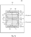
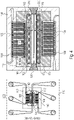
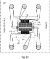
- the gas sensor 100 may include a membrane 110 (e.g., a thin film membrane), a heating element 120 , a first thermocouple structure 130 and a second thermocouple structure 140 .
- the gas sensor can also only have the first thermocouple structure 130 or the second thermocouple structure 140 .
- the membrane 110 can be spanned by a frame 150 and have a first interruption area 160 and a second interruption area 170 .
- the first discontinuous area 160 of the diaphragm 110 may include at least one discontinuous portion 162 and the second discontinuous portion 170 of the diaphragm 110 may include at least one discontinuous portion 172 as well.
- the heating element 120 can be arranged, for example, as a self-supporting bridge structure on the membrane 110 between the first interruption area 160 and the second interruption area 170 of the membrane 110 .
- the first thermocouple structure 130 may have a hot end 132 and a cold end 134 .
- the hot end 132 of the first thermocouple structure 130 may be disposed on the membrane 110 on an opposite side of the first interrupt region 160 from the heating element 120 .
- the second thermocouple structure 140 may also have a hot end 142 and a cold end 144 .
- the hot end 142 may be disposed on the membrane 110 on an opposite side of the second disconnect region 170 from the heating element 120 .
- the membrane 110 can be a thin-layer membrane with a thickness between 200 nm and 4000 nm, 300 nm and 3000 nm, 400 nm and 2000 nm or between 1 ⁇ m and 10 ⁇ m. According to one exemplary embodiment, the thickness of the entire membrane is around 2 ⁇ m (it consists, for example, of several membrane, sensor and passivation layers).
- the membrane layer can e.g. B. Si oxide and / or Si nitride.
- An extension of the membrane 110 into the plane of the page, that is, for example, perpendicular to a surface of the membrane 110 on which the heating element 120, the first thermocouple structure 130 and the second thermocouple structure 140 are arranged, can be defined as the thickness.
- the membrane 110 can comprise conductive material, insulating material or semiconductor material, with the material having a very low thermal conductivity, for example below 5W/(m*K), below 100 mW/(m*K) or below 50 mW/(m*K ), may have.
- a semiconductor with an adapted basic doping can serve as a cost-effective substrate for the production of the membrane 110 in a simple five-mask MEMS process.
- the heating element 120 (the heating element 120 may also be referred to as a heater in the following) may form a cantilevered bridge structure and/or comprise a wire.
- the heating element 120 can be spanned from one side of the frame 150 to an opposite side of the frame 150 .
- a voltage can be applied to the heating element 120, for example, whereby the heating element 120 can transfer heating power to a gas to be analyzed, located for example in the first interruption area 162 and/or in the second interruption area 172.
- the voltage applied to the heating element 120 can be, for example, a periodic voltage signal, such as. B. a sine signal or a periodic square-wave signal.
- the heating element 120 can provide a periodic heater signal (eg the heating power), for example.
- the heater signal may be transmitted to the first thermocouple structure 130 and/or the second thermocouple structure 140, for example, via the membrane 110 and/or via a gas located, for example, in the first break 162 or the second break 172.
- the first thermocouple structure 130 and/or the second thermocouple structure 140 are formed, for example, in a meandering shape, which can correspond, for example, to thermocouples connected in series, which form a thermocouple chain.
- the first thermocouple structure 130 and/or the second thermocouple structure 140 can thus serve as a detector, with the first thermocouple structure 130 and/or the second thermocouple structure 140 being able to detect the heater signal, for example.
- the first thermocouple structure 130 and/or the second thermocouple structure 140 can be completely arranged on the membrane 110 , or at least partially arranged on the membrane 110 and at least partially arranged on the frame 150 .
- a temperature of the frame 150 can serve as a comparison temperature (here, for example, the cold ends 134 of the first thermocouple structure 130 can be arranged and/or the cold ends 144 of the second thermocouple structure 140) and the part of the thermocouple structure that on the membrane 110 (e.g. the hot ends 132, 142) can detect a measurement temperature (e.g. the heater signal).
- the hot ends 132, 142 and the cold ends 134, 144 are connected to a conductor, for example.
- a conductor comprising a first material can connect a first cold end to a first hot end and a second conductor comprising a second material can connect the first hot end to a second cold end.
- a first conductor and a second conductor can represent a thermocouple, which can be connected in series to form a thermal chain, for example, and can thus represent the first thermocouple structure 130 or the second thermocouple structure 140, for example.
- a temperature difference e.g. between the reference temperature and the measurement temperature
- first thermocouple structure 130 and/or the second thermocouple structure 140 may be configured to convert heat into electrical energy.
- the first thermocouple structure 130 and/or the second thermocouple structure 140 may be a wire or a cantilever bridge structure.
- the membrane 110 can be stretched over the frame 150 made of carrier material, which is designed such that the coefficient of thermal expansion and/or a thermal conductivity of membrane material differs from the coefficient of thermal expansion and/or the thermal conductivity of the carrier material.
- the frame 150 may include support material or substrate material with which the membrane 110 may be supported, for example.
- a comparison temperature can be set on the frame 150 .
- the frame 150 and the membrane 110 can also have the same coefficient of thermal expansion.
- the membrane 110 can have a lower thermal conductivity than the frame 150.
- the membrane 110 in particular should have a very low thermal conductivity, for example, so that, for example, the heater signal from the heating element 120 mainly via the gas to be analyzed (arranged, for example, in the first interruption 162 and/or in the second interruption 172) to the first thermocouple structure 130 and/or the second thermocouple structure 140, instead of via the membrane 110.
- heat transport via the membrane 110 can be suppressed, reduced or be slowed down.
- the membrane 110 can thus be formed in order to suppress parasitic heat conduction from the heating element 120 to the first thermocouple structure 130 or to the second thermocouple structure 140 .
- the thermal conductivity of the membrane 110 can be selected, for example, so that little or no heat is conducted from the heating element 120 via the membrane 110 to the first thermocouple structure 130 or the second thermocouple structure 140 and a large part of the heat or the entire heat via the to be analyzed gas is conducted.
- the thermal conductivity of the carrier material of the frame 150 that holds the membrane 110 can be very high.
- a carrier material z. B. silicon with a thermal conductivity of 150 W / (m * K) can be used as a carrier material.
- the carrier material can thus serve as a heat sink.
- the first thermocouple structure 130 and the second thermocouple structure 140 is at least partially, z. B. with the hot ends 132, 142 on the membrane and at least partially, z. B. with the cold ends 134, 144, arranged on the carrier material, whereby a temperature difference can occur within the first thermocouple structure 130 or the second thermocouple structure 140, with the help of which the heat transport from the heating element 120 to the respective thermocouple structure 130, 140 can be detected.
- the cold ends of the first thermocouple structure 130 and the cold ends of the second thermocouple structure 140 can thus be arranged on the carrier material of the frame 150 . They are located, for example, where the membrane 110 is supported by the substrate.
- the first discontinuity region 160 of the membrane 110 can have a continuous discontinuity 162 whose longitudinal extent 164 is large enough to completely cover the region between the first thermocouple structure 130 and the heating element 120 .
- the second discontinuity area 170 of the membrane 110 may have a continuous discontinuity 172 whose longitudinal extent 174 is large enough to completely cover the area between the second thermocouple structure 140 and the heating element 120 .
- the longitudinal extension 164, 174 is, for example, as large as the entire length of the heating element 120 and/or at least as long as the entire length of the first thermocouple structure 130 and/or the second thermocouple structure 140.
- the transverse extent 166 of the at least one interruption 162 of the first interruption area 160 can be different from the transverse extent 176 of the at least one interruption 172 of the second interruption area 170 .
- the transverse extension 166, 176 of the first interruption 162 and the second interruption 172 can be, for example, in a direction perpendicular to a direction of maximum extension of the heating element 120 or in a direction from the heating element 120 to the respective thermocouple structures (e.g. the first thermocouple structure 130 and/or the second thermocouple structure 140).
- the first interruption 162 and the second interruption 172 have the same transverse extent 166, 176.
- the first break 162 may have a longitudinal extent 164 and a transverse extent 166 such that the first break 162 corresponds to the extents of the first break region 160 .
- the second interruption 172 can have a longitudinal extension 174 and a transverse extension 176, for example, so that the second interruption 172 corresponds to the extensions of the second interruption region 170.
- the complete first interruption area 160 can represent the first interruption 162 and the complete interruption area 170 can represent the interruption 172.
- the membrane 110 can have a third and/or a fourth interrupt region on the side of the cold ends 134, 144 of the first thermocouple structure 130 and/or the second thermocouple structure 140.
- the first thermocouple structure 130 can be arranged in the form of a wire or a cantilevered bridge structure between the first interruption area 160 and a third interruption area
- the second thermocouple structure 140 can be arranged, for example, as a wire or as a cantilevered bridge structure between the second interruption area 170 and be arranged in the fourth interruption area.
- the first thermocouple structure 130 and/or the second thermocouple structure 140 can be surrounded by the gas to be analyzed on two sides, for example.
- the first thermocouple structure 130 may have a different distance to the heating element 120 than the second thermocouple structure 140.
- the first thermocouple structure 130 has the same Distance to the heating element 120, like the second thermocouple structure 140.
- the heater signal from the heating element 120 detected by the first thermocouple structure 130 may be referred to as a first sensor signal and the heater signal from the heating element 120 detected by the second thermocouple structure 140 may be referred to as a second sensor signal, for example.
- the first sensor signal and/or the second sensor signal can have, for example, the two unknown heat transfers (e.g.: heating element -> gas, gas -> thermocouple structure) and a heat transfer via the gas to be analyzed.
- the first thermocouple structure 130 is at a different distance from the heating element 120 than the second thermocouple structure 140, then a difference signal can be created by the gas sensor from the first sensor signal and the second sensor signal, for example by using the unknown heat transitions (the first sensor signal can have the same heat transfers as the second sensor signal) can be calculated out and thus the difference signal only or to a large extent has the heat transfer via the gas to be analyzed from the heating element 120 to the respective thermocouple structure 130, 140, but not or to a very small extent Share which has unknown heat transfers.
- first break area 160 and second break area 170 may include multiple breaks (e.g., break 162 and break 162 1 or break 172 and break 172 1 ) that may be arranged such that (e.g., by the remaining membrane material 110) creates a lattice structure (e.g. in the first discontinuity region 160 or the second discontinuity region 170) in which the discontinuities are arranged in rows parallel to the heating element 120 and the rows are arranged offset from one another.
- the interruptions in an interruption area 160, 170 can differ from one another both in the longitudinal extent 164, 174 and in the transverse extent 166, 176. According to Fig.
- the interruption 162 1 of the first interruption area 160 has a smaller longitudinal extension than the longitudinal extension 164 of the interruption 162 .
- the interruption 172 1 of the second interruption region 170 can have a smaller longitudinal extent than the longitudinal extent 174 of the interruption 172.
- the first discontinuity region 160 and the second discontinuity region 170 may include multiple discontinuities, which may be arranged to form a lattice structure in which a thermal conduction path through the membrane 110 is longer than a direct path 122a, 122b.
- the direct path 122a, 122b may be a straight path perpendicular to the heating element 120, from the heating element 120 to the thermocouple structure 130, 140, for example.
- the direct path 122a, 122b can run through the interruptions 162 and 162 1 or through the interruptions 172 and 172 1 , whereby thermal conduction through the gas to be analyzed from the first thermocouple structure 130 and/or the second thermocouple structure 140 can be detected.
- the direct path 122a, 122b would only take place via the membrane 110 and not via the gas to be analyzed, the gas sensor 100 cannot guarantee a meaningful analysis of the gas.
- the at least one interruption 162, 172 in the first interruption area 160 and in the second interruption area 170 can form rectangular sections with optionally rounded corners. This is, for example, a slot. This can also involve oval holes, for example. Even if in Fig. 1a while the discontinuity 162 of the first discontinuity region 160 and the discontinuity 172 of the second discontinuity region 170 are shown as rectangular discontinuities (holes), the discontinuities may have any shape (such as triangular, circular, square, polygonal, etc.).
- the shape of the interruptions 162, 172 can be adjusted so that a heat path from the heating element to the first thermocouple structure 130 and/or to the second thermocouple structure 140 via the membrane 110 is as long as possible and a path via the gas to be analyzed is one very way represents. This enables as much heat as possible to be transported via the gas to be analyzed and not via the membrane 110, as a result of which the gas sensor 100 can analyze the gas very precisely.
- the at least one interruption 162, 172 can be at least three times longer than it is wide.
- the longitudinal extent 164 of the break 162 can be three times longer than the transverse extent 166 or the longitudinal extent 174 of the break 172 can be three times longer than the transverse extent 176.
- the length represents, for example, the longitudinal dimension 164, 174 and the width, for example, the transverse dimension 166, 176.
- the length can be defined, for example, as a direction parallel to the heating element 120 (or to a direction of maximum expansion of the heating element 120) and the Width can be defined as a direction perpendicular to the heating element 120 (or to a direction of maximum extension of the heating element 120).
- a distance 168 between a plurality of interruptions 162, 162 1 in the first interruption region 160 and a distance 178 between a plurality of interruptions 172, 172 1 in the second interruption region 170 can correspond to the smallest structure width that can be realized, which results in a mechanically durable lattice structure.
- the distance 168, 178 can define a width of ridges between two interruptions consisting of membrane material of the membrane 110. FIG. The smaller the distance 168, 178, the less heat is transferred across the membrane 110 from the heating element 120 to the first thermocouple structure 130 and/or the second thermocouple structure 140 and the more heat is transferred via the gas to be analyzed.
- the first thermocouple structure 130 and the second thermocouple structure 140 may be passivated with a protective layer.
- the protective layer can protect the first thermocouple structure 130 and the second thermocouple structure 140 from damage caused by the gas to be analyzed and thus avoid possible inaccuracies in the gas sensor during the gas analysis due to damage to the first thermocouple structure 130 and the second thermocouple structure 140 .
- the hot end 132 of the first thermocouple structure may extend to an edge of the first open area 160 of the membrane 110 and the hot end 142 of the second thermocouple structure 140 may extend to an edge of the second open area 170 of the membrane 110 .
- the distance between the hot end 132 and the first interruption area 160 or the distance between the hot end 142 and the second interruption area 170 should not be greater than 0.5 mm, 100 nm or 10 ⁇ m, for example.
- the interruption 162 or the interruption 142 extends to this edge, the membrane 110 has only a very small distance between the respective hot ends and the respective interruption. This makes it possible for the membrane material of membrane 110 not to affect detection of the heater signal by first thermocouple structure 130 or by second thermocouple structure 140, or only slightly, so that gas sensor 100 can analyze the gas very precisely.
- Fig. 1b shows a schematic representation of an evaluation arrangement 200, which can also be referred to herein as an evaluation device, for a thermal gas sensor 100 with at least one heater 120 and two detectors arranged at different distances 180 1 , 180 2 from the heater 120 (a first detector 130 and a second detector 140).
- the first detector 130 may be spaced from the heater 120 by the distance 180 1 and the second detector 140 may be spaced from the heater 120 by the distance 180 2 .
- Evaluation arrangement 200 can be designed to display information 210 about an amplitude of a detector signal from a first detector 130, information 220 about an amplitude of a detector signal from a second detector 140, information 210 about a first phase difference between a heater signal and the detector signal of the first detector 130 and information 220 about a second phase difference between the heater signal and the detector signal of the second detector 140 to obtain.
- information 210 can include both the amplitude of the detector signal of first detector 130 and the first phase difference between the heater signal and the detector signal of first detector 130, just like information 220 can include both the amplitude of the detector signal of second detector 140 can also include the second phase difference between the heater signal and the detector signal of the second detector 140 .
- the amplitude of the detector signal of the respective detector (the first detector 130 or the second detector 140) to be sent from the thermal gas sensor to the evaluation arrangement separately from the first phase difference or the second phase difference.
- the information 210 and the information 220 not to be transmitted to the evaluation arrangement 200 via separate lines, but for example via a common line or wirelessly.
- the evaluation arrangement 200 can be designed to be an intermediate variable dependent on the information 210, 220 about the amplitudes of the detector signals and to form a combination signal 230 depending on the information 210, 220 about the first phase difference and the second phase difference.
- the combination signal 230 can combine amplitude information and phase information of the detector signal of the first detector 130 and of the detector signal of the second detector 140 .
- the evaluation arrangement 200 can be designed to determine information 240 about a gas concentration or a thermal conductivity of a fluid, for example a gas or gas mixture, based on the combination signal 230 . The evaluation arrangement 200 can carry out this determination, for example, without once again separately considering the individual items of information 210, 220 flowing into the combination signal 230 as the calculations continue.
- the amplitude of the detector signal can, for example, be provided directly as information 210, 220 by the respective detector 130, 140.
- the information 210, 220 about the first phase difference and second phase difference between the heater signal 122 and the detector signal of the respective detector 130, 140 can, for. B. are determined by the thermal gas sensor 100 and transmitted to the evaluation system 200.
- the detector signal of the first detector 130 or the detector signal of the second detector 140 can be transmitted to the evaluation arrangement 200 via the information 210 or the information 220 , and the heater signal 122 can also be transmitted directly to the evaluation arrangement 200 .
- the evaluation arrangement can be designed to determine the respective amplitude from the detector signal of the first detector 130 and from the detector signal of the second detector 140 and to determine the first phase difference and the second phase difference in order to generate the combination signal 230 depending on the information determined in this way form.
- the evaluation arrangement 200 can correct possible errors in the thermal gas sensor 100 very easily and much more quickly in order to obtain the information 240 about the gas concentration and thermal conductivity than if the evaluation arrangement 200 received the information 210 about the Corrected amplitude of the detector signal of the first detector 130 and the first phase difference and the information 220 on the amplitude of the detector signal of the second detector 140 and the second phase difference separately from one another.
- the combination signal 230 can thus make it easier to determine the information 240 about the gas concentration and the thermal conductivity of the gas to be analyzed enable errors generated by the thermal gas sensor 100 to be suppressed or reduced.
- the evaluation arrangement 200 can be designed to obtain information about a heater amplitude, for example information about a heating power from the heater signal 122, and to obtain a linear combination of the information about the heater amplitude, the information 210 and of the information 220 to determine the combination signal 230.
- the evaluation arrangement 200 can not only obtain information about the heater amplitude from the heater signal 122, but also, as already described above, calculate information about the first phase difference and the second phase difference if the information 210, for example, the detector signal of the first detector 130 and the information 220 includes the detector signal of the second detector 140 .
- the heater amplitude which enables the evaluation arrangement 200 as a function of the first distance 180 1 and the second distance 180 2 of the two detectors from the heater 120, which can determine information 240 about the gas concentration and the thermal diffusivity of the gas to be analyzed.
- the detector signal of the first detector 130 has a greater amplitude than the detector signal of the second detector 140, since the distance 180 2 of the second detector 140 from the heater 120 is greater than the distance 180 1 of the first detector 130 from the heater 120.
- the heater amplitude detected by the respective detector 130, 140 can decrease.
- the additional information about the heater amplitude allows the evaluation system 200 to determine the information 240 about the gas concentration and the thermal conductivity even more precisely, since the heater amplitude of the heater signal 122 can be considered as a reference, and the combination signal 230 can therefore be considered a relative May have amplitude signal. For example, a relative amplitude signal is less error-prone than an absolute amplitude signal.
- sigUss can be amplitude information or an amplitude signal that can be dependent on information 210 about the amplitude of the detector signal of first detector 130 and on information 220 about the amplitude of the detector signal of second detector 140 .
- sigUss can be a linear combination of the information 210 about the amplitude of the detector signal of the first detector 130 and the information 220 about the amplitude of the detector signal of the second detector 140 .
- sigPhi may be phase information or an added phase signal, which may be dependent on first phase difference information 210 and second phase difference information 220 .
- sigPhi can be an addition of the information 210 about the first phase difference and the information 220 about the second phase difference.
- Ka and Kp can be constants.
- the combination signal 230 determined in this way can include amplitude information sigUss and phase information sigPhi, whereby four pieces of information (e.g.
- information 210 about the amplitude of the detector signal of the first detector 130, information 220 about the amplitude of the detector signal of the second detector 140, the Information 210 about a first phase difference between the heater signal and the detector signal of the first detector 130 and information 220 about the second phase difference between the heater signal and the detector signal of the second detector 140) are combined in the combination signal 230, whereby the evaluation arrangement 200 can use less power to process the information 210,220.
- the evaluation arrangement 200 can thus be designed to determine information 240 about the gas concentration and thermal conductivity very efficiently, quickly and precisely.
- Hz.Uss can be information about the heater amplitude that can be obtained from the heater signal 122 .
- D1.Uss can be information 210 about the amplitude of the detector signal of the first detector 130 and D2.Uss can be information 220 about the amplitude of the detector signal of the second detector 140 .
- the amplitude information sigUss can thus represent a relative amplitude signal, since the information 210 about the amplitude of the detector signal of the first detector 130, the information 220 about the amplitude of the detector signal of the second detector 140 and the heater amplitude Hz.Uss are offset against each other, so that the detector signal amplitude information 210 of the first detector 130 and the detector signal amplitude information 220 of the second detector 140 can be viewed relative to the heater amplitude.
- the evaluation arrangement 200 can determine the information 240 about the gas concentration and thermal conductivity very precisely.
- the evaluation arrangement 200 can be designed to calculate a polynomial, for example of the first order, of the combination signal 230 in order to obtain the information 240 about the gas concentration or the thermal conductivity.
- the polynomial e.g. polynomial y
- y A0+A1*sigX+A2*sigX 2 , for example.
- the evaluation arrangement 200 can be designed to multiply the polynomial of the combination signal 230 by a correction term in order to obtain the information 240 about the gas concentration and/or the thermal conductivity.
- the correction term of the combination signal 230 can be dependent on information about a pressure and on information about a temperature and can compensate for a pressure and temperature dependency, for example. In other words, the correction term from the combination signal 230 can compensate for a pressure drift and/or a temperature drift. A possible misinterpretation by the evaluation arrangement 200 of the signals detected by the thermal gas sensor 100 is thus reduced.
- sigX can be the combination signal 230
- pol(sigX) can be a polynomial of the combination signal sigX 230
- f(p) can be a function of pressure p
- const1 can be a constant
- f(T) can be a function of temperature T
- const2 can be a second constant.
- f(p) may be a function of a measured pressure p in an environment of thermal gas sensor 100 and f(T) may be a function of a measured temperature T in an environment of thermal gas sensor 100 .
- the second term of the multiplication 1 ⁇ f p signX ⁇ const 1 ⁇ 1 ⁇ f T p ⁇ const 2 can also be used as a correction term of the combination signal 230 to be understood.
- the correction term can be dependent on measurement conditions of the gas sensor 100 (such as an ambient pressure/measurement pressure or an ambient temperature/measurement temperature).
- the correction term can thus correct possible influences of an ambient pressure or an ambient temperature of the thermal gas sensor 100 on the determination of the information 240 about the gas concentration. In this way, possible pressure drift or temperature drift can be suppressed.
- the sigX can be the combination signal 230
- Ay(sigX) can be a polynomial of the combination signal sigX 230 (e.g., first order)
- By(p) can be a function of the pressure p (e.g., a polynomial function, e.g., second order)
- B.ref can be a constant
- Cy(T) can be a function of the temperature T (e.g. a polynomial function, e.g. second order)
- C.ref can be a second constant.
- the function By(p) can be a function of a measured pressure p in an environment of the thermal gas sensor 100 and the function Cy(T) can be a function of a measured temperature T in an environment of the thermal gas sensor 100, for example.
- the second term 1 ⁇ B . y p ⁇ B . ref signX ⁇ B . ref ⁇ 1 ⁇ C . y T ⁇ C . ref p ⁇ C . ref of multiplication to calculate gas concentration information C 240 may define a correction term.
- the correction term can depend on the pressure p and the temperature T, for example.
- By(p) can be a polynomial function depending on the pressure p, whereby, for example, a correction of possible pressure influences on the calculation of the information 240 about the gas concentration can be taken into account.
- Cy(T) a possible influence of the temperature T on the calculation of the information 240 about the gas concentration can be taken into account very precisely.
- the evaluation arrangement 200 can be designed to take into account a pressure and/or a temperature in an environment of the thermal gas sensor 100 when determining the information 240 about the gas concentration and/or the thermal conductivity.
- the thermal gas sensor 100 can have pressure and temperature sensors with which it can detect the pressure and/or the temperature in the environment and transmit it to the evaluation arrangement 200 .
- the evaluation arrangement 200 can, for example, take into account and correct possible miscalculations of the information 240 about the gas concentration and/or the thermal conductivity due to different pressure and/or temperature conditions in the area surrounding the thermal gas sensor 100 .
- the evaluation arrangement 200 can thus react to the pressure and/or the temperature in the area surrounding the thermal gas sensor 100 and accordingly determine the information 240 about the gas concentration and/or the thermal conductivity very precisely.
- evaluation arrangement 200 can be designed to use combination signal 230, information about the temperature in an area surrounding thermal gas sensor 100, when determining information 240 about the gas concentration and/or the thermal conductivity as input variables for a drift correction and using information about a pressure in an environment of the thermal gas sensor 100 to obtain the information about the gas concentration and/or thermal diffusivity as a result of the drift correction.
- the drift correction can be applied to the combination signal depending on the information about the temperature and the pressure in order to obtain the information 240 about the gas concentration and/or the thermal diffusivity.
- the drift correction can, for example, not contain any further variables, but can only use constants previously obtained, for example determined in the course of a calibration.
- the constants can be specific to the thermal gas sensor 100 used.
- the evaluation arrangement 200 can thus be designed to take into account small differences between thermal gas sensors 100 in the calculation of the information 240 about the gas concentration and/or thermal conductivity in order to obtain a very precise result (information 240).
- the drift correction can correct a temperature drift and/or a pressure drift, for example.
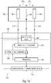
- 1c shows a schematic representation of an exemplary evaluation arrangement 200 for a thermal gas sensor 100 with at least one heater 120 and two detectors (a first detector 130 and a second detector 140).
- the first detector 130 can have a first distance 180 1 from the heater 120 and the second detector 140 can have a second distance 180 2 from the heater 120 .
- the first detector 130 and the second detector 140 have the same distance 180 1 , 180 2 to the heater 120 .
- the first distance 180 1 may differ from the second distance 180 2 .
- the first detector 130 may be spaced a different distance from the heater 120 than the second detector 140 .
- Evaluation arrangement 200 can be designed to calculate a heating power that can be applied to heater 120, depending on at least one sensor signal (e.g.
- a first sensor signal 210 and/or a second sensor signal 220 from at least one of the detectors (e.g. g. the first detector 130 and/or the second detector 140) (for example with a control unit 250 for controlling a heating output) in order to bring the at least one sensor signal 210, 220 into a predetermined value range.
- the detectors e.g. g. the first detector 130 and/or the second detector 140
- a control unit 250 for controlling a heating output
- the at least one sensor signal 210, 220 is brought into the predetermined value range by the evaluation arrangement 200. If the heating power is increased, for example, an amplitude or a frequency of the at least one sensor signal 210, 220 can also be increased, for example. This can be carried out, for example, by evaluation arrangement 200 if the at least one sensor signal 210, 220 is too small and the predetermined value range is very large. The new sensor signal 210, 220 can thus fill out the predetermined value range or lie within it after the heating output has been controlled by the control unit 250.
- the predetermined value range can, for example, depend on the components used in the evaluation arrangement 200, such as e.g. B. an analog-to-digital converter (ADC), be dependent.
- the ADC can, for example, further process the at least one sensor signal 210, 220 very well if the at least one sensor signal 210, 220 is adjusted in the predetermined value range adapted to the ADC (e.g. ADC working range).
- the evaluation arrangement 200 can also be designed to control the heat output of the heater 120 with the control unit 250 such that the heat output of the heater 120 is reduced.
- the at least one sensor signal 210, 220 can also be reduced. This can be advantageous, for example, if the at least one sensor signal 210, 220 exceeds the predetermined value range, ie is too large.
- the fact that the evaluation arrangement 200 is designed to regulate the heating power of the heater 120 with the control unit 250 makes it possible that when the at least one sensor signal 210, 220 is further processed by, for example, components of the evaluation arrangement 200, such as B. the ADC, no or only little information of the at least one sensor signal 210, 220 is lost.
- control unit 250 of the evaluation arrangement 200 can transmit a control signal 252 to the heater 120 in order to control the heating power of the heater 120 .
- control unit 250 can provide information 122 about the controlled heat output of the heater 120 to the evaluation arrangement 200 .
- Evaluation arrangement 200 can be designed to take information 122 about the heating power into account when deriving information 240 about a gas concentration and/or thermal conductivity from the at least one sensor signal 210, 220. It can thus be made possible for the control unit 250 to bring the sensor signal 210, 220 into the predetermined value range and also to take into account the information 122 about the heating power in the analysis, since the at least one sensor signal 210, 220 is dependent on the heating power.
- this evaluation arrangement 200 enables a sensor signal, e.g. B. the first sensor signal 210 or the second sensor signal 220, may be sufficient to derive the information 240 about the gas concentration and / or the thermal conductivity of a gas or fluid (z. B.
- the determination of the information 240 is overdetermined, as a result of which the information 240 can be determined very precisely by the evaluation arrangement 200. If the first distance 180 1 of the first detector 130 differs from the second distance 180 2 of the second detector 140 from the heater 120, then, for example, the information 240 about the gas concentration and/or the thermal conductivity of a gas can also only be obtained from the first sensor signal 210 and be derived from the second sensor signal 220, without the information 122 about the heating output of the heater 120.
- the evaluation arrangement 200 can also receive the information 122 about the heating output from the thermal gas sensor 100 instead of from the control unit 250.
- the evaluation arrangement 200 can be designed to apply a periodic signal (e.g. the control signal 252) to the heater 120 .
- the periodic signal can be a periodic square-wave signal or a sinusoidal signal, for example. If control signal 252, and thus the heat given off by heater 120 to the gas to be analyzed, is a periodic signal, first sensor signal 210 detected by first detector 130 and second sensor signal 220 detected by second detector 140 can also be periodic . Due to the first distance 180 1 and the second distance 180 2 , however, the first sensor signal 210 and/or the second sensor signal 220 can differ in phase from the periodic signal of the heater 120 and in amplitude from the periodic signal of the heater 120. The evaluation arrangement 200 can use these differences, for example, in order to very precisely determine the information 240 about the gas concentration and/or the thermal conductivity.
- the evaluation arrangement 200 can be designed to switch the heating power applied to the heater 120 (for example by the control signal 252) between two values.
- a periodic square-wave signal can be applied to the heater 120 .
- the heater 120 z. B. alternately transmit a first heat output and a second heat output to the gas to be analyzed.
- evaluation arrangement 200 can be designed to regulate an amplitude of the heating power (e.g. with control unit 250) in such a way that both a minimum value of the at least one sensor signal 210, 220 and a maximum value of the at least one sensor signal 210, 220 in the predetermined range of values. If the amplitude of the heating output of heater 120 is increased, for example by control signal 252, then the minimum value of the at least one sensor signal 210, 220 can be reduced and the maximum value of the at least one sensor signal 210, 220 can be increased, for example. If the amplitude of the heating output is reduced by control signal 252, for example, then the minimum value of the at least one sensor signal 210, 220 can be increased and the maximum value of the at least one sensor signal 210, 220 can be reduced.
- the predetermined range of values can be dependent on a range of values of a component, such as e.g. B. an ADC, the evaluation arrangement 200 to be.
- the predetermined value range can be determined as a function of a component value range (for example a component of the evaluation arrangement 200).
- the predetermined value range can specify that the minimum value of the at least one sensor signal 210, 220 should be in a range of 0% to 30%, 1% to 25% or 2% to 20% of the component value range and that the maximum value of the at least a sensor signal 210, 220 should be in a range of 70% to 100%, 75% to 99% or 80% to 98% of the component value range.
- the predetermined value range can thus have, for example, a lower value range in which the minimum value should lie and an upper value range in which the maximum value should lie.
- the evaluation arrangement 200 can be designed to set or regulate an amplitude of the heating power (for example with the control unit 250) such that an amplitude of the at least one sensor signal 210, 220 is in a predetermined amplitude range. If the at least one sensor signal 210, 220 has a periodic sinusoidal signal, for example, then the amplitude of the sensor signal should be within the specified amplitude range at all times. In this case, the amplitude of the at least one sensor signal should utilize the complete predetermined amplitude range.
- the predefined amplitude range can, for example, have/be subdivided into an upper, middle and lower amplitude range.
- the predefined amplitude range is utilized by the amplitude of the at least one sensor signal, a maximum amplitude of the at least one sensor signal should be in the upper range and a minimum amplitude in the lower range.
- the predetermined amplitude range can be dependent on the component area, for example.
- the predefined amplitude range can be determined such that the amplitude of the at least one sensor signal utilizes at least 50% or at least 65% or at least 75% of a component value range of an analog-to-digital converter, for example.
- the evaluation arrangement 200 can be designed to set or regulate sampling times at which a sensor signal 210, 220 can be sampled.
- the sensor signal 210, 220 can optionally be pre-processed, for example, by the evaluation arrangement 200 or the thermal gas sensor 100 and/or be subjected to a DC offset. It can be advantageous if the sensor signal 210, 220 is sampled at a point in time of maximum amplitude and at a point in time of minimum amplitude. These two sampling times can, for example, be set or readjusted by the evaluation system 200 if the evaluation system 200 determines that the sampling times have been selected incorrectly.
- Precise setting of the sampling times can make it possible, for example, for the evaluation arrangement to very easily detect a phase difference or amplitude difference between the first sensor signal 210 and a heater signal (e.g. emitted by the heater 120 and controlled by the control signal 252) or between the second Sensor signal 220 and the heater signal can be determined.
- the evaluation arrangement 200 can very precisely determine or derive the information 240 about the gas concentration and/or thermal conductivity of the gas to be analyzed.
- the evaluation arrangement 200 can be designed to set the sampling times in such a way that sampling, for example with a phase difference of maximum +/- 2°, takes place at a point in time at which the sensor signal 210, 220 reaches a maximum value, and so that the sampling takes place, for example, with a phase difference of maximum +/-2° at a point in time at which the sensor signal 210, 220 reaches a minimum value.
- the maximum value can define a maximum amplitude of the sensor signal 210, 220 and the minimum value can define a minimum amplitude of the sensor signal 210, 220, as already explained above.
- the evaluation device 200 can be designed to combine a sensor signal 210, 220 from at least one of the detectors 130, 140 with an offset signal generated by a digital-to-analog converter to form an input signal for the analog-to-digital converter to obtain.
- the evaluation device 200 can be designed to adjust the offset signal in order to ensure that the input signal of the analog/digital converter remains within a predetermined range over an entire period of the sensor signal 210, 220.
- the offset signal can thus be designed, for example, to adapt the sensor signal 210, 220 in such a way that the input signal that lies in a component value range of the analog/digital converter is produced.
- the offset signal can be adjusted/adapted in order to be able to react to different sensor signals 210, 220 from different gases to be analyzed.
- the offset signal can be designed to to reduce sensor signal 210, 220 that is too large, so that the resulting input signal is within the specified range.
- the offset signal can be designed to increase the sensor signal 210, 220 when the sensor signal 210, 220 is too small, so that an input signal is produced which lies in the predetermined range.
- evaluation arrangement 200 can be designed to bring the amplitude of sensor signal 210, 220 into the predetermined value range by controlling the heating power and to generate an offset of sensor signal 210, 220 by combining sensor signal 210, 220 with the offset signal to change that the sensor signal 210, 220 is in the predetermined value range.
- This makes it possible for the sensor signal 210, 220 to be analyzed very precisely and thus very precise information 240 about the gas concentration and/or thermal conductivity of the gas to be analyzed can be determined by the evaluation arrangement 200.
- the evaluation device 200 can be designed to regulate the heating power only when the sampling times are set or adjusted in a steady state and when the offset signal is adjusted in a steady state.
- a steady state can be understood to mean that the sampling times were determined by the evaluation device 200 in such a way that the sensor signal 210, 220 at predefined events (such as a maximum amplitude (maximum value), a zero crossing or a minimum amplitude (minimum value) ) can be sampled.
- the steady state can also mean that the offset signal has been adjusted in such a way that when the offset signal is combined with the sensor signal 210, 220, the sensor signal 210, 220 generates an input signal that is in the specified range, in order to thus generate the sensor signal 210, 220 can be analyzed very precisely, with little or no loss of information, by means of the evaluation arrangement.
- the evaluation device 200 can determine default settings (such as the sampling times in the steady state or the offset signal in the steady state), so that when the heating power is controlled by the control unit 250, the new sensor signal 210, 220 can be analyzed very precisely with the default settings and, under certain circumstances, no new control of the sampling times or the offset signal is necessary in order to derive the information 240 about the gas concentration and/or the thermal conductivity from the sensor signal 210, 220.
- default settings such as the sampling times in the steady state or the offset signal in the steady state
- the evaluation arrangement 200 can be designed to stop the control of the heating power (for example by the control unit 250) while the sampling times are being set or adjusted and/or while the offset signal is being adjusted. It can thus be ensured, for example, that no changes are made to the sensor signal 210, 220 while the sampling times and the offset signal are not yet in a steady state. It can thus be ensured that the sensor signal 210, 220 can be analyzed very precisely, since the sampling times and the offset signal can be determined very precisely with only very little or no susceptibility to error.
- control unit 250 can, for example, transmit a new heater signal for heater 120 to thermal gas sensor 100 as control signal 252.
- B. has a changed average heat output, maximum heat output or amplitude of the heat output.
- the control signal 152 includes information that states how the average heating power, the maximum heating power or the amplitude of the heating power from the thermal gas sensor for the heater 120 should be changed.
- Fig. 1d shows a schematic representation of an exemplary evaluation arrangement 200 for a thermal gas sensor 100 with at least one heater 120 and two detectors (e.g a first detector 130 and a second detector 140).
- the first detector 130 can have the first distance 180 1 from the heater 120 and the second detector 140 can have the second distance 180 2 from the heater 120 .
- the evaluation arrangement 200 can be designed to apply a periodic signal 260 with a predetermined period to the heater 120 .
- the periodic signal can be, for example, a square-wave signal, a pulsed signal with a known power, or a sinusoidal signal. Optionally, it can also be a sine signal with harmonics or a triangular signal.
- the periodic signal can also be referred to as a heater signal and can be transmitted from the heater 120 in the form of heat to the first detector 130 and/or to the second detector 140 via a gas to be analyzed.
- the transferred heat can be detected by the first detector 130 as the first sensor signal 210 are detected and are detected by the second detector 140 as a second sensor signal 220 .
- the first sensor signal 210 and the second sensor signal 220 can have a first periodic signal or a second periodic signal, each with the specified period. This makes it possible for the gas to be analyzed to be analyzed very precisely with regard to its gas concentration and/or thermal conductivity by the thermal gas sensor 100 or the evaluation arrangement 200 .
- Evaluation arrangement 200 can be designed to sample at least one sensor signal (e.g.
- a second sampling time can, for example, be offset in time by 90° relative to the period duration (for example by +/-2°) compared to a first sampling time.
- the second sampling time can be offset in time by 1/4 period, 5/4 period or by 9/4 period compared to the first sampling time.
- a third sampling time can be offset in time by 180° relative to the first sampling time or by 90° relative to the second sampling time, based on the period duration.
- the first sampling time, the second sampling time and the third sampling time can have a tolerance of +/- 2%.
- the third sampling time can therefore be offset in time by 1/2 period, 3/2 period or 5/2 period compared to the first sampling time.
- the sensor signal 210, 220 can be sampled at precisely defined points, as a result of which information 240 about a gas concentration and/or a thermal conductivity can be determined from the sensor signal 210, 220 very precisely.
- the evaluation arrangement 200 can be designed to recognize, based on three sampled values, which are based on a sampling of the sensor signal at the first sampling time, at the second sampling time and at the third sampling time (carried out by means of the sampling device 270, for example), whether a first sampled value and a third sample representing a maximum value and a minimum value of the sensor signal 210,220.
- Checking device 280 can ignore a DC offset, for example, and thus check, apart from a DC offset, whether the first sampled value represents a maximum value and the third sampled value represents a minimum value of sensor signal 210, 220, for example.
- the second sampling time can thus be a “zero crossing” of sensor signal 210, 220, for example, and can also be taken into account by checking device 280.
- the first sampling time, the second sampling time and/or the third sampling time as well as the first sensor signal 210 and the second sensor signal 220 can be used to provide the information 240 about the gas concentration and/or the thermal conductivity of a gas detected by the thermal gas sensor 100 determine.
- the heater signal 122 can also flow into the determination of the information 240 .
- a phase difference between the first sensor signal 210 and the second sensor signal 220 and an amplitude difference between the first sensor signal 210 and the second sensor signal 220 can be determined, for example, based on the sampling times/sampling values.
- a phase difference and/or an amplitude difference between first sensor signal 210 and heater signal 122 or between second sensor signal 220 and heater signal 122 can also be determined.
- the information 240 about the gas concentration and/or thermal conductivity can be determined from the phase differences and amplitude differences determined in this way.
- the evaluation arrangement 200 can be designed to change the sampling times depending on whether the first sample and the third sample represent a maximum value and/or a minimum value of the sensor signal 210, 220. This can be done by means of a sampling control device 290, for example. Thus, for example, new sampling times can be determined if the first sampling value and the third sampling value do not correspond to a maximum value and/or a minimum value of sensor signal 210, 220. By controlling the sampling times, it can be ensured that the sampled values correspond to predetermined values. If the verification device 280 z. If, for example, it is established that deviations occur outside of a tolerance (for example +/- 2°), the sampling times can be changed/adjusted by the sampling control device 290 .
- a tolerance for example +/- 2°
- evaluation system 200 can be designed to set or regulate the sampling times in such a way that the first sample represents a first extreme value of sensor signal 210, 220, for example a maximum value or minimum value, and the third sample represents a second extreme value, for example the minimum value or represents the maximum value of the sensor signal 210, 220.
- the second sample can, for example, represent an average value or a direct component of the sensor signal 210, 220, such as e.g. B. a "zero crossing".
- evaluation arrangement 200 can be designed to take into account information about a point in time at which sensor signal 210, 220 passes through a predefined threshold value when setting or adjusting the sampling times.
- This point in time can be the second point in time, for example, which can represent a direct component or an average value of sensor signal 210, 220, for example.
- the checking device 280 can use the second sampling time for checking the first sampling time and/or the second sampling time.
- the sampling control device 290 reset or adjust the sampling times.
- the predefined threshold value can, for example, define a "zero crossing" (for example up to a DC offset).
- the evaluation arrangement 200 can be designed to check whether a second sample value at the second sampling time is equal to an average value from the sample value at the first sampling time and the third sample value at the third sampling time and, depending on the check, to recognize whether the first sample and the third sample represent a maximum value and a minimum value of the sensor signal.
- the second sample should be, for example, within a tolerance of at most ⁇ 1% of a difference between the first sample and the third sample or equal to an average of the sample and the second sample. If this is not the case, the checking device 280 can recognize that the sampling times have been selected incorrectly.
- the second sample can lie exactly halfway between the first sample time and the second sample time.
- the second sample can correspond to the average of the other two samples.
- the evaluation arrangement 200 can be designed to apply a periodic square-wave signal 260 with a pulse duty factor of preferably 50% to the heater 120 .
- the periodic square-wave signal it is also possible for the periodic square-wave signal to have a pulse duty factor in the range from 5% to 50%, 8% to 48% or 10% to 45%. That
- the periodic square wave signal 260 applied to the heater 120 may have a tolerance of +/- 2%.
- the duty cycle gives z. B. for a periodic sequence of pulses, a ratio of a pulse duration to a period.
- the evaluation arrangement 200 can be designed to combine a sensor signal 210, 220 with an offset signal generated by a digital-to-analog converter in order to obtain an input signal for an analog-to-digital converter.
- the analog/digital converter can, for example, digitize the signal values present at the sampling times (eg the first sample, the second sample and/or the third sample) and thus sample the sensor signal 210, 220.
- the scanning device 270 can have the analog-to-digital converter, for example.
- the evaluation arrangement 200 can be designed to regulate the offset signal in order to ensure that the input signal of the analog-to-digital converter remains within a predetermined range during an entire period of the sensor signal 210, 220.
- the offset signal can change an offset of the sensor signal 210, 220 in such a way that an input signal is produced which lies within a working range (e.g. the specified range) of the analog/digital converter, so that no information of the sensor signal 210, 220 are lost during digitization or so that a loss of information is reduced.
- the scanning device 270 can check whether an input value of the analog/digital converter exceeds a specified upper threshold value, for example the specified range, or falls below a specified lower threshold value, for example the specified range.
- the sampling device 270 can generate the offset signal, which can be combined with the sensor signal 210, 220 so that the input value, for example a value of the input signal, remains in the predetermined range.
- the evaluation arrangement 200 can be designed to adjust the sampling times after the offset signal has been adjusted and to carry out a new check after a change in the sampling times to determine whether the sampled values obtained with the changed setting of the sampling times are still within the specified range.
- the offset signal can first be generated by means of the evaluation arrangement 200 for the sensor signal 210, 220 and then sampling times can be determined by means of the sampling device 270, checked and, if necessary, readjusted (this can represent a tracking of the sampling times, for example).
- This tracking can result in new sampling values, which can entail a renewed adjustment of the offset signal by the evaluation arrangement 200.
- the offset signal and the sampling times can always be adjusted or tracked alternately until, for example, the analog/digital converter can process the sensor signal 210, 220 further.
- the offset signal and the sampling times can be in a steady state.
- the settings of the sampling times changed by the sampling control device 290 generate new sample values, for example, which can be regarded as input values of the analog/digital converter.
- Both the offset signal and the heating power of the heater 120 can be readjusted so that the input signal of the analog/digital converter remains within the specified range.
- the offset signal can adjust an offset of the sensor signal 210, 220, for example, and the change in the heating power can adjust an amplitude of the sensor signal 210, 220, so that an input signal is produced that lies in the predetermined range.
- evaluation arrangement 200 can be designed to regulate a heating power applied to heater 120 as a function of at least one sensor signal 210, 220 from at least one of detectors 130, 140, in order to convert the at least one sensor signal 210, 220 in bring a predetermined range of values.
- the evaluation arrangement 200 can be designed to take into account information about the heating power (e.g. the heater signal 122) when deriving information 240 about a gas concentration and/or thermal conductivity from the sensor signals 210, 220.
- the sensor signal 210, 220 can experience an increase in the amplitude of the sensor signal 210, 220, or when the heating output decreases, the at least one sensor signal 210, 220 can experience a reduction in the amplitude of the sensor signal 210, 220 Experienced.
- the sensor signal 210, 220 can be brought into the predetermined value range by controlling the heat output of the heater 120.
- thermal gas sensor and the evaluation arrangement are described below with reference to further figures.
- FIG 2a and Figure 2b each show a schematic representation of a gas sensor 100 for measuring physical gas properties.
- the thermal gas sensor 100 can have a thin-film membrane 110 and a heating element 120, which can be arranged, for example, as a cantilevered bridge structure on the membrane 110 between a first interruption area 160 of the membrane 110 and a second interruption area 170 of the membrane 110.
- a thickness of the thin-film membrane 110 (it consists, for example, of several base, sensor and passivation layers) in the case of a wire sensor (an example of the temperature sensor structures 130, 140; see 2 and 3 ) e.g. B. between 1-10 microns.
- the heating element 120 can also be referred to as a heater.
- the complete first discontinuity area 160 may include a discontinuity 162 of the membrane 110 and the complete second discontinuity area 170 may include a discontinuity 172 of the membrane.
- the heating element 120 may be cantilevered between the first interruption 162 and the second interruption 172 .
- the first interruption 162 may be bounded by the heating element 120 and a first temperature sensor structure 130 in the form of a cantilever bridge structure.
- the second interruption 172 can be delimited by the heating element 120 and by a second temperature sensor structure 140, for example in the form of a cantilevered bridge structure.
- the first temperature sensor structure 130 and/or the second temperature sensor structure may be a wire sensor, thermopiles, temperature variable resistors, or thermistors.
- the gas sensor 100 may include a first outer break 192 and a second outer break 194 .
- the first thermocouple structure 130 may be a cantilevered bridge structure between the first interrupt 160 and the second outer interrupt 194 and the second thermocouple structure 140 may be a cantilevered bridge structure between the second interrupt 172 and the first outer interrupt 192.
- the first thermocouple structure 130 may also be referred to as a first detector or first sensor and the second thermocouple structure 140 may also be referred to as a second sensor or second detector.
- the gas sensor 100 includes, for example, a frame 150 made of carrier material.
- the frame 150 made of carrier material can span the membrane 110, for example.
- the membrane 110 may have a thickness 111 (e.g., an extent perpendicular to a surface of the membrane 110 on which the first thermocouple structure 130, the second thermocouple structure 140 and the heating element 120 are arranged) in a range of 1 ⁇ m to 50 ⁇ m, 2 ⁇ m to 25 ⁇ m or 3 ⁇ m to 10 ⁇ m ⁇ m, e.g. B. 8 microns.
- the membrane 110 can be implemented by a recess 190 in the frame 150 .
- the recess 190 can be chosen such that a membrane 110 with the desired thickness 111 can be realized.
- the recess 190 can be designed in such a way that only the heating element 120, the first thermocouple structure 130 and the second thermocouple structure 140 remain stretched between the frame 150.
- a surface of the membrane 110 on which the first thermocouple structure 130, the second thermocouple structure 140 and the heating element 120 are arranged has an expansion in a range from 200x200 ⁇ m 2 to 5x5 mm 2 , 500x500 ⁇ m 2 to 2000 ⁇ 2000 ⁇ m 2 or 800 ⁇ 800 ⁇ m 2 to 1200 ⁇ 1200 ⁇ m 2 , it being possible for the expansion to be a square or rectangular expansion.
- the gas sensor 100 can have a thickness 101 (e.g.
- An expansion of the gas sensor 100, parallel to the surface of the membrane 110 on which the heating element 120 is arranged, can be in a range from 1x1 mm 2 to 1x1 cm 2 , 1.5x1.5 mm 2 to 9x9 mm 2 or from 2x2 mm 2 to 8x8 mm 2 , such as B 6.5x2.5 mm 2 .
- the first thermocouple structure 130, the second thermocouple structure 140 and/or the heating element 120 can be part of the membrane 110.
- a microchip (example of the thermal gas sensor 100) with three filigree bridge structures (e.g. the heating element 120, the first thermocouple structure 130 and the second Thermocouple structure 140) are used, which can be surrounded as microwires from the gas to be analyzed.
- the gas to be analyzed may be located in the first break 162, the second break 172, the first outer break 192, and/or in the second outer break 194.
- a central bridge structure can be designed as a heater 120 and two on both sides in different ones Detector structures remote from heater 120 (e.g., first thermocouple structure 130 and second thermocouple structure 140) may be used as temperature sensors to measure a transmission response from the gas mixture.
- the central wire (the heating element 120) is supplied with a heating signal, for example a periodic one, whereby heat is radiated from the heating element, for example.
- a heat transfer can occur via unknown heat transfers from the heater 120 into the gas to be analyzed and from the gas into the sensor wire (e.g. into the first thermocouple structure 130 and/or the second thermocouple structure 140).
- the heat transfer thus detected by the first thermocouple structure 130 and/or the second thermocouple structure 140 can be understood as a transfer response or as a sensor signal (e.g. a first sensor signal detected by the first thermocouple structure 130 and a second sensor signal detected by the second thermocouple -Structure 140).
- a temperature response e.g.
- the transmission response with, for example, two identical sensors (e.g. the first thermocouple structure 130 and/or the second thermocouple structure 140) at different distances from the heater 120, the unknown heat transfers in of the measurement setup.
- the phase and amplitude of the two sensor signals can essentially depend on the heat transfer through the gas.
- a first variant of the thermal gas sensor 100 can be constructed on the basis of a silicon-on-insulator (SOI) wafer substrate. It consists, for example, of a microchip with self-supporting, filigree bridge structures made of silicon microwires (eg the first temperature sensor structure 130 and the second temperature sensor structure 140), which are spanned in the gas space to be analyzed.
- a middle wire can be designed as a heater 120 and two detector wires (e.g. the first temperature sensor structure 130 and the second temperature sensor structure 140) can serve as temperature sensors on either side of the heater at different distances from it (see Fig Figure 2a , Figure 2b ).
- Figure 2a shows, for example, a photo of the MEMS wire sensor chip (the gas sensor 100) on a light microscope (left)
- Figure 2b shows, for example, a close-up of structures in a scanning electron microscope (right).
- 3 12 shows a schematic representation of a silicon bridge 120/130/140, which can be used, for example, for a heating element, a first thermocouple structure and/or a second thermocouple structure of a gas sensor.
- a silicon bridge 120/130/140 shows 3 a detail of a micro-bridge (SEM, Scanning Electron Microscope) of a thermal MEMS wire sensor (e.g. a gas sensor).
- the silicon bridge 120/130/140 shown can be produced by SOI technology, for example.
- a substrate or support material of a frame 150 may include oxide 152 material, silicon 154 material, and aluminum 156 material.
- silicon material 154 can be at least partially removed, for example, in order to implement incisions 158 (for example trenches) in the carrier material of frame 150 and thereby implement silicon bridge 120/130/140.
- the silicon bridge 120/130/140 can be arranged on the membrane 110 (e.g. consisting of oxide material 152).
- the membrane 110 can have, for example, a first interruption area 160/162 and a second interruption area 170/172. Both the first interruption area 160/162 and the second interruption area 170/172 have an interruption, for example, which can be a cavity, for example.
- the membrane 110 can have a first interruption 162 and a second interruption 172 in which the gas to be analyzed can be arranged and receive heat transfer from the silicon bridge 120/130/140, for example, if the silicon bridge constitutes a heating element 120 or to the silicon bridge 120/130/140 when the silicon bridge 120/130/140 represents the first thermocouple structure 130 and/or the second thermocouple structure 140.
- the silicon bridge 120/130/140 can be contacted through the aluminum material 156, whereby the aluminum material 156 can serve as a bond pad, for example.
- an exciting heater signal can be applied to the heating element 120 through the bond pad or the first thermocouple structure 130 and/or the second thermocouple structure 140 can be read (for example a first or second sensor signal).
- the gas sensor 100 for example, as a MEMS thermopile sensor on a thin-film membrane in combination with the evaluation algorithm according to Section 1.3 (can be used optionally in combination with the signal generation and evaluation according to Section 1.2)
- FIG. 4 shows a schematic representation of a gas sensor 100 on the left side and a detailed view of the gas sensor 100 on the right side.
- the gas sensor 100 may include a membrane 110 and a heating element 120 that may be disposed on the membrane 110 between a first discontinuous area 160 of the membrane 110 and a second discontinuous area 170 of the membrane 110 .
- the first break area 160 may include a break 162 and the second break area 170 may include a break 172 .
- the first interruption 162 and/or the second interruption 172 may have a longitudinal dimension parallel to a direction of maximum extension of the heating element 120 (which may be referred to as a heater, for example) and a transverse dimension, for example in a direction perpendicular to a direction of maximum extension of the heating element 120 , exhibit. According to 4 the first interruption 162 can thus have a greater transverse extent than the second interruption 172. Furthermore, the first interruption 162 and the second interruption 172 according to FIG 4 have the same longitudinal extent. The first interruption 162 and the second interruption 172 have, for example, the longitudinal extent that is so large that the first interruption 162 and the second interruption 172 the area between the first thermocouple structure 130 and the second thermocouple structure 140 and the Cover heating element 120 completely.
- both the first interruption 162 and the second interruption 172 is along the entire length of the heating element 120. This can prevent a large part of the heat radiated from the heating element 120 from being transported across the membrane 110. It can thus be achieved that a large part of the heat is transferred to the respective thermocouple structure 130, 140 via the gas arranged in the first interruption 162 and in the second interruption 172.
- the first thermocouple structure 130 can have a different distance from the heating element 120 than the second thermocouple structure 140, for example 4 For example, the first thermocouple structure 130 has a greater distance to the heating element 120 than the second thermocouple structure 140.
- the first Thermocouple structure 130 can, for example, detect a first heat transfer 210, from the heating element 120 to the gas in the first interruption 162 and from the gas to the first thermocouple structure 130, and record it as the first sensor signal.
- the second thermocouple structure 140 can, for example, detect a second heat transfer 220 from the heating element 120 to the gas in the second interruption 172 and from the gas to the second thermocouple structure 140 and provide it as a second sensor signal.
- thermocouple structure 130 and the second thermocouple structure 140 Due to the different distance of the first thermocouple structure 130 and the second thermocouple structure 140 from the heating element 120, a difference signal can be formed from the first sensor signal and the second sensor signal, whereby unknown transitions (e.g. a transition from the heating element to the Gas or from the gas to the respective thermocouple structure) can be calculated and thus z.
- unknown transitions e.g. a transition from the heating element to the Gas or from the gas to the respective thermocouple structure
- the gas sensor 100 can also have a frame 150 that can span the membrane 110 .
- the first thermocouple structure 130 and the second thermocouple structure 140 may be at least partially disposed on the membrane 110 and at least partially disposed on the frame 150 .
- the first thermocouple structure 130 and the second thermocouple structure 140 can have hot ends 132, 142 which are arranged to face the heating element 120.
- the first thermocouple structure 130 and the second thermocouple structure 140 may have cold ends 134, 144 located on a side of the first thermocouple structure 130 and the second thermocouple structure 140, respectively, opposite the side having the hot ends 132, 142 can be arranged and are thus arranged away from the heating element 120 .
- hot ends 132, 142 may be located on diaphragm 110 and cold ends 134, 144 may be located on frame 150.
- the frame 150 can have a different material than the membrane 110.
- the cold ends 134, 144 can be subjected to a reference temperature through the frame material of the frame 150, in relation to a temperature measured by means of the hot ends 130, 142 transmitted from the heating element 120.
- the left representation of the gas sensor 100 can be a layout and the right side of the 4 a photo of the gas sensor 100 (z. B. a MEMS membrane sensor) for measuring, for example, a gas type-dependent heat transport (embodiment according to aspect 1).
- a variant of the gas sensor 100 with a constant break e.g., a first break 162 and a second break 172
- the constant interruption 162, 172 causes z. B. that a major portion of a heat transport between a heater 120 and the detectors (z. B. the first thermocouple structure 130 and the second thermocouple structure 140) z. B. necessarily takes place via the measurement gas volume enclosed between the two elements, for example via the measurement gas arranged in the first interruption 162 and in the second interruption 172.
- thermopile structures 130, 140 detectors
- the membrane sensor e.g., the gas sensor 100
- the membrane sensor requires only 1/3 of the heating energy with identical sensitivity to the gas concentration of a binary mixture.
- the heater structure e.g the heating element 120
- the heater structure is, for example, centered as a cantilever filigree bridge structure stretched in a measuring space of the gas to be detected.
- the two detector wires arranged on both sides of the heater 120 (for example) at different distances can be replaced by "thermopile" (thermo chain) structures (e.g.
- thermocouple structure 130 and/or the second thermocouple structure 140 which can lie on the laterally spanned membrane surfaces (of the membrane 110) and which can extend, for example, to the edge of the pit (eg an edge of the first interruption 162 or the second interruption 172).
- the cold ends 134, 144 of the thermal chains (thermopiles) 130, 140 should be the carrier material (e.g. of the frame 150), which can have a high thermal conductivity (e.g. silicon approx. 150 W/(m*K)) and as Heat sink can serve (heat sink close to room temperature), contact immediately.
- the carrier material e.g. of the frame 150
- the base membrane material material of the membrane 110
- the excess temperature e.g. measured using the hot ends 132, 142
- a measuring point for temperature compensation is mechanically connected, for example, directly on or with the silicon chip (eg the frame 150).
- membrane 110 can be consistently interrupted so that heat transport 210, 220 from heater 120 can be done to the detectors 130, 140 mainly over a shortest lateral distance and thus z.
- B. traverses a distance across an intermediate volume of the measurement gas (e.g., located in the first disruption 162 and the second disruption 172).
- the gas-type-dependent transmission response eg the first sensor signal and the second sensor signal
- FIG. 5 on the left side a schematic representation of the gas sensor 100 and on the right side an enlarged detailed view of the gas sensor 100.
- the gas sensor 100 from FIG figure 5 may have the same features and functionality as gas sensor 100 4 have, wherein the gas sensor 100 from figure 5 from the gas sensor 100 on 4 in an embodiment of the first interruption area 160 or the second interruption area 170.
- the first disconnection area 160 of the gas sensor 100 can be off figure 5 have a plurality of breaks 162 i and the second break region 170 can also have a plurality of breaks 172 i .
- the index i of the interruptions 162 i of the first interruption area 160 of the gas sensor 100 can go from 1 to 23, since the first interruption area 160 according to the exemplary embodiment in figure 5 23 may have interruptions.
- the index i of the interruptions 172 i of the second interruption area 170 of the gas sensor 100 can go from 1 to 14, for example, since the second interruption area 170 according to an exemplary embodiment of FIG figure 5 14 may have interruptions.
- the index i of both the breaks 162 i and the breaks 172 i can define a natural number, where the index i z. B. indicates how many interruptions 162 i , 172 i in an interruption area 160, 170 are present.
- the interruptions 162 i , 172 i can be arranged in rows parallel to a direction of maximum extension of the heating element 120 in the first interruption area 160 or in the second interruption area 170 and the rows can also be arranged offset in relation to one another.
- This has the effect, for example, that a parasitic heat conduction 114a, 114b in the membrane 110 runs through as long a path as possible.
- the interruptions 162 i , 172 i are arranged, for example, in such a way that a lattice structure is formed in the membrane 110, in which a path of a parasitic heat conduction 114a, 114b through the membrane 110 is longer than a direct path 210, 220.
- a direct path 210, 220 may be, for example, a straight path perpendicular to the heating element 120, from the heating element 120 to the respective thermocouple structure 130, 140, with the direct path 210, 220 passing through a gas to be analyzed located in the discontinuities 162 i , 172 i can.
- the path of parasitic heat conduction 114a, 114b through membrane 110 should not be a straight line, but rather a tortuous path as illustrated in FIG figure 5 , form.
- the interruptions 162 i , 172 i can be, for example, elongated interruptions that are perpendicular to a main direction of heat conduction, for example with a tolerance of +/- 20° (for example, the direct path 210, 220 from the heating element 120 to the thermocouple Structures 130, 140) may lie.
- the interruptions 162 i , 172 i can be rectangular cutouts with rounded corners. These can also be referred to as oblong holes, for example, and they can also be oval holes, for example.
- the interruptions 162 i , 172 i can be at least three times longer than they are wide.
- the length can be defined, for example, as a direction parallel to a maximum extension of the heating element 120 and the width, as a direction perpendicular to the maximum extension of the heating element 120.
- the interruptions 162 i , 172 i in the first interruption area 160 or the second interruption area 170 can be arranged in such a way that a distance 116a, 116b between the interruptions 162 i , 172 i has a smallest structure width that can be realized, which has a mechanically durable Lattice structure results corresponds to.
- the distance 116a, 116b is, for example, a width of webs made of membrane material of the membrane 110. The smaller the distance 116a, 116b is realized, the lower a parasitic heat conduction 114a, 114b can be, whereby the quality of an analysis of a gas by the gas sensor 100 is increased can be.
- the distance 116a, 116b should be selected in such a way that the lattice structure in the membrane 110 created by the interruptions 162i , 172i is mechanically stable in order to ensure a high quality of the gas analysis by the gas sensor 100.
- figure 5 show a layout of a MEMS membrane sensor (e.g. the gas sensor 100), for example for measuring the gas-type-dependent heat transport (e.g. via the direct path 210, 220) (embodiment according to aspect 1).
- the gas sensor 100 can be off figure 5 represent a variant with a lattice structure made of the membrane material of the membrane 110 to increase the mechanical stability of the gas sensor 100 .
- the geometric shape of the grid can be selected in such a way that the parasitic heat conduction 114a, 114b in the membrane material has to cover as long a path as possible.
- figure 5 shows another embodiment of the gas sensor 100, which shows a lattice structure between the heater 120 and detector elements (e.g. the first thermocouple structure 130 and the second thermocouple structure 140), which increases the mechanical stability of the gas sensor 100 in long-term operation should improve.
- detector elements e.g. the first thermocouple structure 130 and the second thermocouple structure 140
- Such an arrangement can reduce the gas-type-dependent sensitivity of the thermal gas sensor 100, since the thermal conduction can now also take place parasitically 114a, 114b via the lattice webs of the membrane material.
- some of the thermal energy periodically introduced into the heater 120 may arrive earlier in time to the detector structures (e.g., the first thermocouple structure 130 and the second thermocouple structure 140) than the portion of the thermal energy that is transported through the measurement gas over the laterally shortest distance 210, 220.
- thermocouple structure 130 Due to the thermal mass of the detectors (e.g. the first thermocouple structure 130 or the second thermocouple structure 140), which can respond to periodic excitation as a low-pass filter, e.g. B.
- Both heat wave propagation times e.g. the parasitic heat line 114a with the heat transfer via the direct path 210 or the parasitic heat line 114b with the heat transfer via the direct path 220
- a single sinusoidal detector signal e.g. to a first sensor signal or to a second sensor signal.
- the geometric shape of the grid is selected, for example, so that the parasitic heat conduction 114a, 114b in the membrane material has to cover as long a path as possible.
- the holes which are oval for example (for example the interruptions 162 i , 172 i ), are for example transverse to the main direction of heat conduction.
- the aspect ratio of the oval holes is, for example, at least three times longer than it is wide, the web width (e.g. the distance 116a, 116b) corresponds, for example, to the smallest structure width that can be realized, which results in a mechanically durable lattice structure with the existing layer technology.
- Figure 6a , Figure 6b and Figure 6c show schematic representations of further exemplary embodiments of a gas sensor 100.
- the gas sensor 100 can Figure 6a , Figure 6b and Figure 6c the same features and functionalities as the gas sensor 100 4 and or figure 5 exhibit. Differences between the gas sensors 100 may occur in the first disconnection area 160 and the second disconnection area 170 of the gas sensor 100 .
- the gas sensor 100 can turn off Figure 6a have, for example, eight interruptions 162 i in the first interruption area 160 and eight interruptions 172 i in the second interruption area 170 .
- the interruptions 162 i can have a greater transverse extent than the interruptions 172 i .
- the interruptions 162 i , 172 i can have different longitudinal extents within their respective interruption area 160 or 170 .
- the gas sensor 100 off Figure 6b has, for example, a first interruption area 160 with eight interruptions 162 i and a second interruption area 170 with a continuous interruption 172.
- a first interruption area 160 with eight interruptions 162 i and a second interruption area 170 with a continuous interruption 172.
- the variants Figure 6a respectively. figure 5 and from 4 combined with each other.
- the gas sensor 100 off Figure 6c has, for example, a first interruption area 160 and a second interruption area 170 with a plurality of interruptions 162 i , 172 i , wherein the first interruption area 160 can have, for example, 23 interruptions 162 i and the second interruption area 170 can have, for example, 14 interruptions 172 i .
- the interruptions 162 i , 172 i of an interruption region 160 or 170 can have the same transverse extent and/or the same longitudinal extent.
- Figure 6a , Figure 6b and 6c represent further layout variants of the MEMS membrane sensor (e.g. the gas sensor 100), which differ in the number and size of the perforations of the membrane (e.g. the interruptions 162 i , 172 i ) (embodiments according to aspect 1).
- the thermal sensor 100 (the gas sensor can also be referred to herein as a thermal sensor):
- the spatial separation between the heater 120 and sensor structures 130, 140 (the first temperature sensor structure and the second temperature sensor structure can also be referred to herein as sensor structures, detector structures, sensors, temperature sensors or detectors) with thermal coupling through the gas mixture to be analyzed; and the measurement with sensor structures 130, 140.
- the sensor structures 130, 140 can be arranged at different distances from the heater 120 or at the same distance.
- the sensor signals 210, 220 have a sinusoidal curve (see e.g. 9 ), which is strongly dependent on the thermal properties of the gas surrounding the sensor structures.
- transmitted and received periodic temperature waves are compared (see 9 ).
- the CO 2 content in air can be 0.2 vol%, z. B. by means of the gas sensor. Since gases are compressible and their density changes as a result of pressure and temperature, the corresponding drifts should be compensated for.
- the received sensor signals 210, 220 differ in amplitude, offset and phase position.
- the signals 210, 220 are difference signals from a signal of a first thermocouple structure and a second thermocouple structure of the gas sensor.
- Thermal conductivity, temperature conductivity and, if the density of the gas is known, the specific heat capacity can be determined by evaluating other measured variables supplied by the sensor - a possible way of also analyzing unknown gas mixtures.
- the parasitic thermal decoupling between heater and detector elements is largely achieved and the signal quality is significantly increased. Due to the heater's low thermal mass, it is possible to modulate the heater at frequencies up to 300 Hertz, as the heat can be supplied and removed quickly.
- a model according to [ Baehr 2008 ] can be used to determine the thermal conductivity with sinusoidal heating power 122 to describe the propagating temperature field.
- T x t T m + T A ⁇ n ⁇ e ⁇ k 1 ⁇ x ⁇ sin 2 ⁇ f ⁇ t ⁇ k 1 ⁇ x + e
- the temperature wave oscillates harmonically with the same angular frequency as its excitation and decays rapidly with increasing penetration depth in the medium, while the phase shift increases. Penetration depth and wavelength increase with increasing oscillation period and thermal conductivity of the medium.
- the damping of the amplitude is thus also a measure of the thermal conductivity of the medium.
- the thermal conductivity ⁇ of the medium is represented by the mean temperature distribution in the measuring room.
- an average temperature is set at the temperature detectors, which is in proportion to the heat flow that flows through the gaseous medium from the heater via the detectors to the housing wall flows.
- the temperatures of the heater and the detectors must be known. B. the control of a detector (preferably the one closer to the heater) to a constant (excessive) temperature if the required mean heating energy is determined as a measure for the thermal conductivity.
- the basic principle for measuring the thermal conductivity of gases is that in a flow-free measuring room with a free-standing heater element in the gas (e.g. a hot wire or a "hot plate” - hot plate) an excess temperature above the ambient temperature is generated.
- a condition for correct measurement is a still gas in the measuring room, e.g. B. in a dead volume or behind a diffusion barrier, since convective heat flow leads to a measurement error [Baar 2001] .
- the task of the electronics and signal evaluation is to use a miniaturized system that is as inexpensive as possible, e.g. B. to generate a reliable measurement result that is directly dependent on the gas concentration.
- the gas sensor according to the invention should be able to be used in a respiratory gas monitor in which the carbon concentration in the air mixture can change with high dynamics.
- the gas sensor should be able to resolve changes in the gas composition in the ventilation cycle of inspiration and expiration up to a rate of 60 strokes per minute. A rapid evaluation of the sensor signals is therefore desirable.
- 10 shows an electrical circuit diagram of a heater control for a thermal gas sensor.
- a CPU gives z. B. a lower and upper heater voltage and switches back and forth between these two values controlled by a timer.
- a CPU can measure the current heater current at specific times to calculate the heater power.
- 10 represents a heater supply with voltage specification and current measurement.
- a square-wave signal is generated on the developed ⁇ controller electronics (for example). Due to the timer structures in the processor, this can be generated much more precisely in terms of time than a synthetic sinusoidal signal that would be output by the processor on its digital/analog (DA) port.
- DA digital/analog
- 2 heater voltages are specified via a DA converter.
- the DA converter is controlled via SPI, and the time from which a new DA value is accepted is not exactly the same as the one selected Processor module (CPU) can be determined.
- this is a prerequisite for being able to determine the phase position of the sensor response.
- one of the two voltages is alternately applied to the heater amplifier via an analog switch, for example. So that the steep switching edges spread less in the system, they are smoothed out, for example, by a downstream low-pass filter.
- the operational amplifier (OP) circuit boosts the voltage to the voltage level required by the heater. Another OP compensates, for example, for the voltage drop that occurs at the current measuring resistor. Since the current is measured and the heater voltage is known, the heater power can be calculated. This is important because heater resistance can vary with temperature.
- a heater duty cycle of 50% may be used (eg, a periodic square wave having a duty cycle of, for example, 50% +/-2% is applied to the heater).
- shorter duty cycles can also be used, for example in the range of 5..50%.
- the heater output is not adjusted by controlling the duty cycle - this is more difficult on the MSP430, but interesting when using more powerful ⁇ controllers: You can work with a fixed operating voltage and only change the duty cycle (a kind of PWM control).
- the heater power can be adjusted by changing the voltage levels (the voltage applied to the heater) or the current levels (the current flowing through the heater or heating element). The two options can also be combined.
- FIG. 11 shows an electrical circuit diagram of a detector signal evaluation of a thermal gas sensor.
- Both a first thermocouple structure and a second thermocouple structure of the gas sensor can 11 shown detector signal evaluation, in order to detect heat transmitted from a heating element of the gas sensor to the first thermocouple structure and the second thermocouple structure via a gas to be analyzed in a respective detector signal (e.g. detected by means of the first thermocouple structure or the second thermocouple structure and can also be referred to herein as a sensor signal).
- a sensor signal e.g. detected by means of the first thermocouple structure or the second thermocouple structure and can also be referred to herein as a sensor signal.
- the detector signal evaluation of the sensor 1 shown.
- the detector signal evaluation z. B configured to receive a first input signal, z. B.
- a CPU controls a heater so that an amplitude of the sensor signal stays in an ADC range.
- a magnifying glass function z. B. kept the sensor signal within the ADC limits.
- a phase evaluation is carried out e.g. B. via the comparator using the MSP430 timer structures (time structures).
- a change in resistance of the sensor wire is very small. For this reason, a high gain amplifier is preferred or needed. Since an absolute value of an input voltage (e.g. the sensor signals) depends on many factors, it is advisable to compensate this value.
- a direct current (DC) amplifier was used, which has no phase shift.
- the negative input connection at the differential input of the operational amplifier (OP) is raised to the mean value of the detector signal and actively tracked using a software controller, the digital-to-analog converter (DAC) of the
- processor outputs this voltage directly. Due to the differential mode of operation of the differential input on the OP, the DC components of the input voltages are subtracted from one another and only the AC component of the signal is amplified. To do this, in one aspect, the analog-to-digital converted (ADC) signal is measured and checked to see if it is within reasonable limits detectable by the ADC. If the signal hits the upper or lower voltage limit of the OP, the DAC value is adjusted accordingly. The result is an amplifier in which the amplified signal is continuously kept in the optimal working range or working window, whereby the amplification factor on the OP can be increased by removing the DC component, a kind of "magnifying glass function". The DAC value required for compensation can be used as a further parameter for evaluation, with which the absolute mean detector temperature can be determined and the thermal conductivity of the gas mixture can be determined via the relationship from equation (5).
- ADC analog-to-digital converted
- a Schmitt trigger for example, was used to determine the phase position of the sensor signal. It is set to switch just above or below the zero crossing of the sensor signal. Here the signal is at its steepest and thus causes the smallest phase noise.
- the DC component is removed via a capacitor, for example. This makes it possible to determine the phase of the sensor response.
- FIG. 12 shows a schematic representation of nested software controllers for a thermal gas sensor.
- the innermost is the DC operating point controller. For example, only when this has settled (no adjustment of the DC offset was necessary), then the tracking of the sampling times takes place.
- the amplitude control loop the amplitude of S1 is kept constant, for example - but only if no adjustment of the DC offset and sampling time was necessary.
- the heating energy required to regulate the S1 amplitude can be regulated in such a way that the thermal System can dynamically adapt to a wide range of different gas mixtures.
- FIG. 12a A block diagram is shown in FIG. 12a, which represents an exemplary regulation and tracking of the DC operating points of the two detector amplifiers.
- FIG 13b a block diagram is shown which represents an exemplary tracking of the sampling times for the amplitude measurement of the detector signals and S1 amplitude controller.
- controllers e.g. B. the evaluation of the gas mixture with the measured values for amplitude and phase of the detectors.
- Figures 13a and 13b can be viewed as a block diagram, where Figure 13b With 13a is connected via the "Tracking of the sampling times" block.
- timing table e.g. B. for the gas sensor
- phase difference D1-Hz.dPhi red
- D2-Hz.dPhi blue
- phase difference D2-D1.dPhi green, right y-axis
- amplitudes measured at the detectors D1 and D2 as well as a sum signal of the amplitudes formed relative to the heater amplitude are shown as examples via the CO 2 dependence of the sensor.
- the amplitude D1.Uss (red) at detector 1 and the amplitude D2.Uss (blue) at detector 2 are displayed. Both amplitude signals fall z. B. with an increase in the CO2 concentration, ie with an increase in the thermal conductivity in the gas mixture.
- a sensor signal can be highly dependent on pressure and temperature. In order to correctly determine the gas properties, the transverse effects should therefore be known and corrected by the algorithms.
- the pressure influence shows a linear relationship
- the temperature influence a quadratic one, as calculated theoretically. Both cross-sensitivities are of the order of magnitude of the signal for the gas concentration itself.
- FIG. 12 shows a plot of a sensor signal for phase versus frequency when measured in CO 2 .
- Figure 17a a diagram of a phase shift in 100% CO 2 as a function of frequency. The phase goes into saturation.
- FIG. 12 shows a plot of a sensor signal for amplitude versus frequency when measured in CO 2 .
- Figure 17b a plot of amplitude in 100% CO 2 versus frequency. The amplitude drops towards zero.
- the heating power When measuring in combustible gases, the heating power should be slightly reduced compared to air, so that the system does not exceed its A/D range.
- the heating power it has been found that in practice it makes sense to operate the system with the largest possible sensor amplitudes and thus obtain more stable signals than to set the heating power to a minimum, at which the sample gas is thermally less influenced , but the signal-to-noise ratio also decreases.
- the heating energy periodically entered into the sensor must cover the sample volume within this period, e.g. B. can leave, so it does not heat up steadily. For example, a peak heat output of approx. 26 mW at 120 Hz was permanently set for three measuring systems that were set up.
- the sensor behavior represents an ideal first-order low-pass filter, there are no harmonic spectral components in the sensor signal. Because of this, actively sweeping through a frequency spectrum yields no additional information. So it was decided to operate the sensor at a fixed frequency, the electronics effort for the system could be reduced, the necessary measurement time to obtain a reliable value is significantly shorter. (all optional)
- phase resolution, phase difference and amplitude for different gas mixtures gave the best phase response at a frequency of e.g. B. 120 Hz at a heating power of 26 mW for the microwire sensor and 160 Hz at approx. 8 mW for the MEMS thermopile sensor on a thin-film membrane. (details optional)
- phase signal of a sensor for methane with increasing admixture of nitrogen As an almost linear behavior.
- it is the phase signal depending on the nitrogen concentration in methane as a phase difference D1-Hz.dPhi (red) between heater and detector 1, with a 200 ⁇ m distance, a phase difference D2-Hz.dPhi (blue) between heater and detector 2, with a 300 ⁇ m distance, and a phase difference D2-D1.dPhi (green, right y-axis) between detector 2 and detector 1 is shown.
- the relative amplitude signal sigUss 2*Hz.Uss-(D1.Uss+D2.Uss) (green, right y-axis) with increasing N 2 concentration.
- 20 shows a diagram of a calculated sensor signal sigX (an example for a combination signal of the gas sensor) from phase and amplitude for different combustible gas mixtures.
- 20 shows the sensor signal (an example of a combination signal of the gas sensor) for different fuel gases and their mixtures: methane, ethane and propane, as well as the mixtures: methane95-ethane05, methane93-ethane05-CO202, methane91-ethane05-CO204, methane91-ethane05- CO202-propane02, methane90-ethane10 and natural gas-L (the 2-digit numbers denote the percentage of the gas components by volume).
- Methane, ethane and propane show clear differences to each other, but the methane mixtures with shares of 2 vol% to 10 vol% of other gases also differ from each other.
- the sensor signal shows strong pressure and temperature dependencies.
- the cross effects are known and corrected.
- the pressure influence shows a linear correlation
- the temperature influence a quadratic one. Both cross-sensitivities are of the order of magnitude of the signal for the gas concentration itself.
- the factors Ka and Kp are constants with which both partial signals are multiplied.
- the added phase signal sigPhi is formed, for example, from the sum of the two phase differences for the propagation times between the rising edge of the heater pulse and the rising edges at the detectors.
- signPhi D 1 ⁇ Hz . phi + D 2 ⁇ Hz . phi where (D1-Hz).phi and (D2-Hz).phi are intended to represent the phase differences between the heater and the detectors.
- phase difference between the heater and the detectors increases with increasing CO 2 concentration, ie with increasing thermal diffusivity, but the two amplitudes at the detectors fall with increasing thermal diffusivity ( 15 ).
- the signal sigX calculated from phase and amplitude moves, for example, in the range between (1.7..2.0) for (0..6) vol% CO 2 .
- the device e.g. the gas sensor
- the device was measured in a temperature range between (16..28)°C and in the barometric pressure field between (900..1200) mbar.
- the strong pressure and temperature dependency of the sensor signal should be compensated in order to be able to deduce a gas concentration from the measured value.
- the green line 230b of the calibration curve can be shifted towards a current working pressure with the aid of a pressure-dependent polynomial function.
- the red line 230a corresponds to the average of all blue lines 230 1 to 230 16 and is a characteristic curve of the sensor signal to the gas concentration normalized to an average temperature and an average pressure.
- the characteristic curves of the sensor signal sigX are plotted from the measured variation for each temperature and an average gas concentration over the pressure (see 22 ), one also obtains a set of straight lines shifted parallel to each other. Higher pressures and cold gas, ie gas molecules lying closer together, result in a higher sensor signal, while low pressures and warm gas result in a lower signal sigX.
- the 22 thus shows a pressure dependency of the sensor signal sigX for a mean fixed gas concentration, family of curves from different temperatures.
- the bottom line 230 1 describes the connection at the highest temperature of 28°C in the variation and the top line 230 7 represents the pressure dependency of the signal at 16°C.
- Regression level A describes the relationship between the gas concentration of the calibration reference and the sensor signal sigX .
- the regression level B describes the pressure drift of the sensor signal sigX .
- the 1st derivative of the curve should be formed and the increase in the reference point should be calculated from this.
- CO 2 volume % A . y signX ⁇ 1 ⁇ B . y p ⁇ B . ref signX ⁇ B . ref ⁇ 1 ⁇ C . y T ⁇ C . ref p ⁇ C . ref
- Ay(sigX) , By(p) and Cy(T) correspond to the respective complete polynomials for the measurement signal, the gas pressure and the gas temperature.
- 24 shows a block diagram of a schematic procedure for determining a gas concentration, taking into account the influences of pressure and temperature from the sensor signal sigX formed.
- 24 shows 24 a schematic representation of the formation of the sensor signal sigX from amplitudes and phases as well as the determination of a gas concentration from sigX taking into account the influence of pressure and temperature (example).
- the thermal conductivity a of the gas mixture In addition to calibrating the sensor signal to the concentration of a known gas mixture, it is also possible to determine the thermal conductivity a of the gas mixture directly. In 25 the theoretically calculated thermal conductivity was plotted against the sensor signal sigX. In other words shows 25 the thermal conductivity versus the sensor signal sigX at constant pressure and constant temperature in a mixture of carbon dioxide CO 2 in nitrogen N 2 . The thermal diffusivity 240 1 (red line) falls with increasing CO 2 concentration 240 2 (green line).
- 26 , 27 and 28 show a diagram in which a heating voltage 300 applied to a heater of a gas sensor, a current flow 310 during a heating period 302, measuring times 320 for an optional ADC (analog-to-digital converter) of an exemplary evaluation arrangement and a comparator signal for a detector (e.g B. for a first detector or for a second detector).
- the evaluation arrangement is z. B. designed to obtain the information on how much heat is dissipated by the heater during the heating period 302, based on a measurement of the current flow 310 through the heater at a given heating voltage 300.
- the evaluation arrangement is designed to obtain the current flow 310 shortly after the specified heating voltage 300 is switched on and shortly before the specified heating voltage is switched off. This means e.g. B. that a start peak 312 of the heating current 310 and a heating current end value 314 of the current flow 310 can be processed by the evaluation arrangement.
- the starting peak 312 always has the same value for one and the same gas sensor (small fluctuations of less than 1%, 0.5% or 0.1% may possibly occur). According to the in the Figures 26 to 28 In the examples shown, the start peak 312 is always at 2.93V and approx. 400 ⁇ s after switching on. This value of the starting peak 312 is for a gas sensor in the Figures 26 to 28 shown. For other gas sensors, the value of the start peak 312 may differ from that shown in FIGS Figures 26 to 28 shown value. It should be noted here that the value of the start peak 312 can deviate not only between different gas sensors, but also between gas sensors of the same construction.
- a gas or gas mixture is analyzed by a gas sensor and/or an evaluation arrangement.
- a gas mixture with 10% CO 2 and 90% N 2 (nitrogen) according to the example 27 the gas is nitrogen (100% N 2 ) analyzed and according to the example 28 the gas oxygen (100% O 2 ) is analyzed.
- nitrogen 100% N 2
- the gas oxygen 100% O 2
- the evaluation arrangement processes (examines) the difference in the heating current (the current flow 310) between the switch-on and switch-off moment, ie between the cold and hot heater.
- the CO 2 mixture from 26 shows compared to the examples 27 and 28 the highest heater temperature and thus the lowest heating current (e.g. the lowest heating current final value 314) is reached here, since CO 2 has only half the thermal conductivity of N 2 and O 2 .
- the heater achieved according to 27 in 100 vol.% N 2 does not show the end temperature (e.g. the heating current end value 314) as in the 10% CO 2 -90% N 2 mixture 26 .
- the heater reaches according to 28 in 100 vol.% O 2 does not show the end temperature (e.g. the heating current end value 314) as in the 10% CO 2 -90% N 2 mixture 26 .
- the difference between turn-on and turn-off current in 28 is the lowest at 210 mV and accordingly the gas analyzed here also has the highest thermal conductivity in comparison to the 10%CO 2 -90%N 2 mixture (see 26 ) and the 100 vol.% N 2 (see 27 ) on.
- a measurement effect is minimal since the heater e.g. B. is highly doped to z. B. to be able to heat 3 V.
- the TKR (temperature coefficient) of the heater can be low (e.g. ⁇ 6*10 -3 1/K, ⁇ 4.1*10 -3 1/K, ⁇ 3.9*10 -3 1/K).
- a sensor signal (z. B. the current flow 310) used to distinguish the concentration of a third gas can.
- Emergency ventilation involves working with increased oxygen concentrations. So it is common to use a mixture of 50% by volume O 2 in N 2 . Without correction of the sensor signal at a higher oxygen concentration compared to the fresh gas during a calibration , the gas sensor (e.g. a CO 2 sensor ) shows a concentration of - 5% CO2 on. This means that the change in the third gas component, a change in the concentration of oxygen, in the mixture may lead to an error signal in the CO 2 sensor.
- a concentration mixture of about 56% oxygen and 5% CO 2 in nitrogen N 2 shows the sensor as z. For example, assume a CO 2 concentration of 0 vol.%, as in the fresh gas calibration with 21 vol.% O 2 and approx. 78 vol.% N 2 .
- the sensor would e.g. B. show erroneous values.
- the heater is operated with a constant voltage (which according to the Figures 26 to 28 corresponds to a value of 3000 digits at a D/A output, but this is only an example and can be freely selected).
- a constant voltage which according to the Figures 26 to 28 corresponds to a value of 3000 digits at a D/A output, but this is only an example and can be freely selected.
- a voltage signal is obtained which is proportional to the heating current.
- Screen shots of the signals recorded on the oscilloscope are shown, with the heater current curve (the current flow 310) being greatly enlarged (the noise can be reduced by shielding the measuring lines).
- a product of heating voltage 300 and measured heating current 310 enables z.
- B. a statement about the heating capacity.
- the heater current 310 decreases somewhat over time as the heater heats up and increases its internal resistance due to its resistance temperature gradient (TCR). Due to the higher internal resistance, less current can flow with the same heating voltage (I Hz ⁇ 1/R Hz ).
- phase signals can represent the phase information sigPhi for the evaluation arrangement according to an embodiment.
- the information 210 about the first phase difference the information 220 about the second phase difference, a phase sum 400 (information 210 + information 220) and a phase difference 410 (information 220 - information 210) are shown.
- the phase information 210, 220, 400 and 410 can also be recorded at other environmental parameter settings (different temperature, different pressure).
- a first section (e.g. measuring points 4520 to 4620) represents the respective phase information 210, 220, 400 and 410 for a 10 vol.% CO 2 in N 2 gas mixture
- a second section (e.g. measuring points 4670 to 4780 ) the respective phase information 210, 220, 400 and 410 for a 100 vol vol% O 2 Gas. Times between the individual sections are z. B. Waiting times until the respective mixture is adjusted.
- the phase sum 400 represents e.g. B. a stable sum signal D1+D2 (D1 corresponds to detector 1 and D2 corresponds to detector 2 ) of the phase positions. B. all phase information available. According to the exemplary embodiment, the largest signal difference occurs between 10% by volume of CO 2 and 0% by volume of CO 2 in N 2 . Since the phase difference signal 410 is currently very noisy, the phase sum 400 is preferred as phase information.
- information 210 about an amplitude of a detector signal of a first detector and information 220 about an amplitude of a detector signal of a second detector are displayed.
- the amplitude information 210 and 220 can also be acquired at other environmental parameter settings (different temperature, different pressure).
- a first section (e.g. measuring points 4520 to 4650) represents the respective amplitude information 210, 220 for a 10% by volume CO 2 in N 2 gas mixture
- a second section e.g. measuring points 4670 to 4810 the respective amplitude information 210, 220 for a 100% by volume N 2 gas
- a third section e.g. measuring points 4960 to 5120 the respective amplitude information 210, 220 for a 100% by volume O 2 gas. Times between the individual sections are z. B. Waiting times until the respective mixture is adjusted.
- the information 210 about the amplitude of the detector signal of the first detector and the information 220 about the amplitude of the detector signal of the second detector represent z. B. represent stable amplitude signals, wherein D2 (the second detector) according to this embodiment has a larger noise, since its amplitude is lower than the amplitude at D1 (the first detector) (about 5mV to 1.8mV in air).
- D2 the second detector
- D1 the first detector
- Figure 12 shows a combination signal sigX 230 (with the right y-axis) and a CO 2 reference signal 500 (with the left y-axis).
- a first section (e.g. measurement points 4610 to 4650) represents the combination signal sigX 230 for a 10% by volume CO 2 in N 2 gas mixture
- a second section (e.g. measurement points 4700 to 4810) represents the combination signal sigX 230 for a 100 vol.% N 2 gas
- a third section (e.g. measuring points 4960 to 5100) the combination signal sigX 230 for a 100 vol.% O 2 gas.
- Times between the individual sections are z. B. Waiting times until the respective mixture is adjusted.
- An NDIR reference detector detects z. B. only a CO 2 concentration and can not distinguish between N 2 and O 2 .
- the gas sensor is a membrane sensor.
- the thermal gas sensor based on membrane and thermopile technology with a perforated membrane can be designed to minimize the parasitic heat transport via the membrane or the suspension of the structures in order to obtain a higher gas-sensitive signal.
- the gas sensor can have electronics, wherein the electronics can have one or more of the following aspects, individually or in combination.
- the electronics can have a DC sensor amplifier with an operating point that is tracked via software.
- the electronics can be designed to carry out a measurement of the phase position via the internal timer structure of the ⁇ controller (MSP430), with z. B. the precise generation of the heater excitation signal via the analog switch is used via the internal timer structure of the ⁇ Controller (MSP430).
- the electronics can be designed to carry out a measurement of the phase position of the sensor signals via a Schmitt trigger, which measures the sensor signals freed from the DC offset in the zero point crossing, since the signals are steepest there and the phase noise is therefore minimized.
- the electronics include regulation of the heating power via S1 amplitude regulator and/or regulation of the timing of the sampling.
- the gas sensor can have a calibration.
- the calibration can be designed to form a pseudo signal from phase and amplitude, with the emphasis in signal formation and formula being able to be on a pseudo signal.
- aspects have been described in the context of a device, it is understood that these aspects also represent a description of the corresponding method, so that a block or a component of a device is also to be understood as a corresponding method step or as a feature of a method step. Similarly, aspects described in connection with or as a method step also constitute a description of a corresponding block or detail or feature of a corresponding device.
- Some or all of the method steps may be performed by hardware apparatus (or using a hardware Apparatus), such as a microprocessor, a programmable computer, or an electronic circuit. In some embodiments, some or more of the essential process steps can be performed by such an apparatus.
- embodiments of the invention may be implemented in hardware or in software. Implementation can be performed using a digital storage medium such as a floppy disk, DVD, Blu-ray Disc, CD, ROM, PROM, EPROM, EEPROM or FLASH memory, hard disk or other magnetic or optical memory, on which electronically readable control signals are stored, which can interact or interact with a programmable computer system in such a way that the respective method is carried out. Therefore, the digital storage medium can be computer-readable.
- a digital storage medium such as a floppy disk, DVD, Blu-ray Disc, CD, ROM, PROM, EPROM, EEPROM or FLASH memory, hard disk or other magnetic or optical memory, on which electronically readable control signals are stored, which can interact or interact with a programmable computer system in such a way that the respective method is carried out. Therefore, the digital storage medium can be computer-readable.
- some embodiments according to the invention comprise a data carrier having electronically readable control signals capable of interacting with a programmable computer system in such a way that one of the methods described herein is carried out.
- embodiments of the present invention can be implemented as a computer program product with a program code, wherein the program code is effective to perform one of the methods when the computer program product runs on a computer.
- the program code can also be stored on a machine-readable carrier, for example.
- exemplary embodiments include the computer program for performing one of the methods described herein, the computer program being stored on a machine-readable carrier.
- an exemplary embodiment of the method according to the invention is therefore a computer program that has a program code for performing one of the methods described herein when the computer program runs on a computer.
- a further exemplary embodiment of the method according to the invention is therefore a data carrier (or a digital storage medium or a computer-readable medium) on which the computer program for carrying out one of the methods described herein is recorded.
- the data carrier, digital storage medium, or computer-readable medium is typically tangible and/or non-transitory.
- a further exemplary embodiment of the method according to the invention is thus a data stream or a sequence of signals which represents the computer program for carrying out one of the methods described herein.
- the data stream or sequence of signals may be configured to be transferred over a data communication link, such as the Internet.
- Another embodiment includes a processing device, such as a computer or programmable logic device, configured or adapted to perform any of the methods described herein.
- a processing device such as a computer or programmable logic device, configured or adapted to perform any of the methods described herein.
- Another embodiment includes a computer on which the computer program for performing one of the methods described herein is installed.
- a further exemplary embodiment according to the invention comprises a device or a system which is designed to transmit a computer program for carrying out at least one of the methods described herein to a recipient.
- the transmission can take place electronically or optically, for example.
- the recipient may be a computer, mobile device, storage device, or similar device.
- the device or the system can, for example, comprise a file server for transmission of the computer program to the recipient.
- a programmable logic device e.g., a field programmable gate array, an FPGA
- a field programmable gate array may cooperate with a microprocessor to perform any of the methods described herein.
- the methods are performed on the part of any hardware device. This can be hardware that can be used universally, such as a computer processor (CPU), or hardware that is specific to the method, such as an ASIC.
- the devices described herein may be implemented, for example, using hardware apparatus, or using a computer, or using a combination of hardware apparatus and a computer.
- the devices described herein, or any components of the devices described herein may be implemented at least partially in hardware and/or in software (computer program).
- the methods described herein may be implemented, for example, using hardware apparatus, or using a computer, or using a combination of hardware apparatus and a computer.
Landscapes
- Life Sciences & Earth Sciences (AREA)
- Health & Medical Sciences (AREA)
- Physics & Mathematics (AREA)
- General Physics & Mathematics (AREA)
- Chemical & Material Sciences (AREA)
- Engineering & Computer Science (AREA)
- Analytical Chemistry (AREA)
- Pathology (AREA)
- Immunology (AREA)
- General Health & Medical Sciences (AREA)
- Biochemistry (AREA)
- Biomedical Technology (AREA)
- Molecular Biology (AREA)
- Fluid Mechanics (AREA)
- Medicinal Chemistry (AREA)
- Food Science & Technology (AREA)
- Urology & Nephrology (AREA)
- Hematology (AREA)
- Biophysics (AREA)
- Investigating Or Analyzing Materials Using Thermal Means (AREA)
- Investigating Or Analyzing Materials By The Use Of Electric Means (AREA)
- Investigating Or Analyzing Materials By The Use Of Fluid Adsorption Or Reactions (AREA)
Priority Applications (2)
| Application Number | Priority Date | Filing Date | Title |
|---|---|---|---|
| EP21190705.0A EP3926335B1 (de) | 2018-01-05 | 2019-01-07 | Auswerteanordnung für einen thermischen gassensor, verfahren und computerprogramm |
| EP22196711.0A EP4141430B1 (de) | 2018-01-05 | 2019-01-07 | Auswerteanordnung für einen thermischen gassensor, verfahren und computerprogramm |
Applications Claiming Priority (2)
| Application Number | Priority Date | Filing Date | Title |
|---|---|---|---|
| EP18150496 | 2018-01-05 | ||
| PCT/EP2019/050261 WO2019135002A2 (de) | 2018-01-05 | 2019-01-07 | Auswerteanordnung für einen thermischen gassensor, verfahren und computerprogramme |
Related Child Applications (3)
| Application Number | Title | Priority Date | Filing Date |
|---|---|---|---|
| EP22196711.0A Division EP4141430B1 (de) | 2018-01-05 | 2019-01-07 | Auswerteanordnung für einen thermischen gassensor, verfahren und computerprogramm |
| EP21190705.0A Division EP3926335B1 (de) | 2018-01-05 | 2019-01-07 | Auswerteanordnung für einen thermischen gassensor, verfahren und computerprogramm |
| EP21190705.0A Division-Into EP3926335B1 (de) | 2018-01-05 | 2019-01-07 | Auswerteanordnung für einen thermischen gassensor, verfahren und computerprogramm |
Publications (2)
| Publication Number | Publication Date |
|---|---|
| EP3735580A2 EP3735580A2 (de) | 2020-11-11 |
| EP3735580B1 true EP3735580B1 (de) | 2022-04-27 |
Family
ID=60990632
Family Applications (3)
| Application Number | Title | Priority Date | Filing Date |
|---|---|---|---|
| EP19700107.6A Active EP3735580B1 (de) | 2018-01-05 | 2019-01-07 | Auswerteanordnung für einen thermischen gassensor, verfahren und computerprogramme |
| EP21190705.0A Active EP3926335B1 (de) | 2018-01-05 | 2019-01-07 | Auswerteanordnung für einen thermischen gassensor, verfahren und computerprogramm |
| EP22196711.0A Active EP4141430B1 (de) | 2018-01-05 | 2019-01-07 | Auswerteanordnung für einen thermischen gassensor, verfahren und computerprogramm |
Family Applications After (2)
| Application Number | Title | Priority Date | Filing Date |
|---|---|---|---|
| EP21190705.0A Active EP3926335B1 (de) | 2018-01-05 | 2019-01-07 | Auswerteanordnung für einen thermischen gassensor, verfahren und computerprogramm |
| EP22196711.0A Active EP4141430B1 (de) | 2018-01-05 | 2019-01-07 | Auswerteanordnung für einen thermischen gassensor, verfahren und computerprogramm |
Country Status (8)
| Country | Link |
|---|---|
| US (3) | US11686695B2 (https=) |
| EP (3) | EP3735580B1 (https=) |
| JP (3) | JP7561619B2 (https=) |
| KR (2) | KR102558160B1 (https=) |
| CN (2) | CN112055811B (https=) |
| AU (2) | AU2019205103B2 (https=) |
| CA (2) | CA3088990C (https=) |
| WO (1) | WO2019135002A2 (https=) |
Families Citing this family (12)
| Publication number | Priority date | Publication date | Assignee | Title |
|---|---|---|---|---|
| JP7561619B2 (ja) | 2018-01-05 | 2024-10-04 | ハーン-シッカート-ゲゼルシャフト フュア アンゲヴァンテ フォアシュング アインゲトラーゲナー フェライン | 熱ガスセンサの評価装置、方法およびコンピュータプログラム |
| US11073415B2 (en) | 2019-10-21 | 2021-07-27 | Flusso Limited | Thermal fluid flow sensor having a dielectric membrane comprising discontinuities between the heating element and an edge |
| JP7452323B2 (ja) * | 2020-08-18 | 2024-03-19 | 株式会社デンソー | ガス濃度検出装置 |
| WO2022079535A2 (en) * | 2020-10-13 | 2022-04-21 | Alcon Inc. | Apparatus and methods for gas verification |
| EP4009008B1 (en) * | 2020-12-03 | 2024-01-31 | Sensirion AG | Fault detection in a thermal sensor device |
| EP4198504B1 (en) * | 2021-12-17 | 2025-07-02 | Sensirion AG | Thermal sensor device and method for determining concentration of a target gas in a gas sample |
| DE102022209906A1 (de) * | 2022-09-20 | 2024-03-21 | Hahn-Schickard-Gesellschaft für angewandte Forschung e.V. | Sensoranordnung |
| DE102022209905A1 (de) * | 2022-09-20 | 2024-03-21 | Hahn-Schickard-Gesellschaft für angewandte Forschung e.V. | Sensoranordnung |
| DE102022127043B4 (de) * | 2022-10-15 | 2024-05-23 | Sensirion Ag | Driftkompensation für einen Sensor zur Messung der Konzentration eines Stoffes in einem Fluid |
| DE102022214190A1 (de) * | 2022-12-21 | 2024-06-27 | Vitesco Technologies GmbH | Verfahren zur Diagnose eines Gaskonzentrationssensors, Gaskonzentrationssensor, Computerprogramm und computerlesbares Medium |
| US12596085B2 (en) * | 2023-07-17 | 2026-04-07 | Posifa Technologies Inc. | Method and apparatus for simultaneously measuring air contained hydrogen and water vapor concentrations via a single MEMS thermal conductivity sensor |
| EP4610642A1 (de) * | 2024-02-29 | 2025-09-03 | Hahn-Schickard-Gesellschaft für angewandte Forschung e. V. | Verfahren und thermischer sensor zur detektion von mikroplastik |
Citations (7)
| Publication number | Priority date | Publication date | Assignee | Title |
|---|---|---|---|---|
| US20080044939A1 (en) * | 2002-01-24 | 2008-02-21 | Nassiopoulou Androula G | Low power silicon thermal sensors and microfluidic devices based on the use of porous sealed air cavity technology or microchannel technology |
| EP2175246A1 (en) * | 2008-10-09 | 2010-04-14 | Sensirion AG | A method for measuring a fluid composition parameter by means of a flow sensor |
| EP1840535B1 (en) * | 2006-03-31 | 2011-01-12 | Sensirion Holding AG | Flow sensor with thermocouples |
| EP2348292A1 (en) * | 2010-01-13 | 2011-07-27 | Sensirion AG | Sensor device |
| EP2869041A1 (de) * | 2011-08-31 | 2015-05-06 | Hahn-Schickard-Gesellschaft für angewandte Forschung e.V. | Strömungssensor zur Bestimmung eines Strömungsparameters und Verfahren zur Bestimmung desselben |
| EP2887057A1 (en) * | 2013-12-17 | 2015-06-24 | Sensirion AG | Device and method of humidity compensated gas concentration monitoring by thermal conductivity measurements |
| WO2019034570A1 (de) * | 2017-08-14 | 2019-02-21 | Hahn-Schickard-Gesellschaft für angewandte Forschung e.V. | Sensoranordnung mit drucksensor und thermischem gassensor |
Family Cites Families (52)
| Publication number | Priority date | Publication date | Assignee | Title |
|---|---|---|---|---|
| US3866108A (en) * | 1971-12-06 | 1975-02-11 | Westinghouse Electric Corp | Control system and method for controlling dual fuel operation of industrial gas turbine power plants, preferably employing a digital computer |
| US4259835A (en) * | 1978-02-06 | 1981-04-07 | Westinghouse Electric Corp. | System and method for monitoring industrial gas turbine operating parameters and for providing gas turbine power plant control system inputs representative thereof |
| JPH0493648A (ja) | 1990-08-03 | 1992-03-26 | Yamatake Honeywell Co Ltd | ガスクロマトグラフ |
| DE4338200A1 (de) * | 1993-11-09 | 1995-05-11 | Efu Ges Fuer Ur Umformtechnik | Verfahren zur Messung der Temperatur von metallischen Werkstücken oder ihres Feststoffanteils im teilerstarrten Zustand |
| JP3370801B2 (ja) | 1994-11-02 | 2003-01-27 | リコーエレメックス株式会社 | 温度補償付き雰囲気検出装置 |
| US5897836A (en) * | 1996-12-19 | 1999-04-27 | J And N Associates, Inc. | Thermal gas sensing apparatus |
| US10130787B2 (en) | 1997-06-17 | 2018-11-20 | Fisher & Paykel Healthcare Limited | Humidity controller |
| US6169965B1 (en) | 1997-12-31 | 2001-01-02 | Honeywell International Inc. | Fluid property and flow sensing via a common frequency generator and FFT |
| US6019505A (en) | 1997-12-31 | 2000-02-01 | Honeywell Inc. | Time lag approach for measuring thermal conductivity and specific heat |
| US6079253A (en) | 1997-12-31 | 2000-06-27 | Honeywell Inc. | Method and apparatus for measuring selected properties of a fluid of interest using a single heater element |
| JP4093333B2 (ja) * | 1998-07-08 | 2008-06-04 | アルバック理工株式会社 | 熱物性測定方法と装置 |
| EP1144958B1 (de) * | 1998-12-22 | 2004-03-24 | Sensirion AG | Verfahren und sensor zur messung eines massenflusses |
| DE19944181A1 (de) * | 1999-09-15 | 2001-04-12 | Bosch Gmbh Robert | Sensor zur Bestimmung der Konzentration von Gaskomponenten in Gasgemischen |
| DE19949327A1 (de) * | 1999-10-13 | 2001-04-19 | Grunewald Axel Ulrich | Verfahren und Einrichtung zur Bestimmung der Gaskonzentrationen in einem Gasgemisch |
| JP3843880B2 (ja) | 2001-05-31 | 2006-11-08 | 株式会社デンソー | ガス濃度センサのヒータ制御装置 |
| GR1004040B (el) | 2001-07-31 | 2002-10-31 | Μεθοδος για την κατασκευη αιωρουμενων μεμβρανων πορωδους πυριτιου και εφαρμογης της σε αισθητηρες αεριων | |
| CA2513126A1 (en) * | 2003-01-23 | 2004-08-05 | Ems-Patent Ag | Increased-accuracy gas energy meter |
| JP4500904B2 (ja) * | 2005-01-31 | 2010-07-14 | 一平 鳥越 | 熱伝達特性測定方法および装置 |
| JP4662339B2 (ja) | 2005-02-04 | 2011-03-30 | エプソンイメージングデバイス株式会社 | 液晶表示パネル |
| DE102005023695A1 (de) * | 2005-05-23 | 2006-11-30 | Robert Bosch Gmbh | Verfahren und Vorrichtung zur Korrektur der Alterung eines Gasmessfühlers |
| DE102005059304B3 (de) * | 2005-12-09 | 2007-05-31 | Areva Np Gmbh | Verfahren und Einrichtung zum Kalibrieren eines Feuchtigkeitssensors |
| DE102006054505A1 (de) | 2006-11-20 | 2008-05-29 | Escube Gmbh & Co. Kg | Vorrichtung und Verfahren zur Bestimmung der Konzentration eines Stoffes in einem Gas |
| US7780343B2 (en) | 2007-07-09 | 2010-08-24 | Siargo Ltd. | Micromachined gas and liquid concentration sensor and method of making the same |
| DE102008047511A1 (de) | 2007-09-13 | 2009-03-19 | Weinmann Geräte für Medizin GmbH + Co. KG | Vorrichtung und Verfahren zur Atemgasanalyse |
| US8174416B2 (en) * | 2007-09-28 | 2012-05-08 | Nxp B.V. | Automatic common-mode rejection calibration |
| US8331892B2 (en) * | 2008-03-29 | 2012-12-11 | Qualcomm Incorporated | Method and system for DC compensation and AGC |
| JP4983726B2 (ja) | 2008-05-29 | 2012-07-25 | トヨタ自動車株式会社 | ガス濃度センサの暖機制御装置 |
| JP5745205B2 (ja) | 2008-08-22 | 2015-07-08 | 木村 光照 | 加熱励振を利用した熱伝導型気圧センサ |
| FR2949155B1 (fr) * | 2009-08-14 | 2012-04-06 | Neosens | Procede de mesure ou de detection de l'encrassement d'un reacteur |
| JP5055349B2 (ja) | 2009-12-28 | 2012-10-24 | 日立オートモティブシステムズ株式会社 | 熱式ガスセンサ |
| DE102011075519A1 (de) * | 2011-05-09 | 2012-11-15 | Innovative Sensor Technology Ist Ag | Verfahren und Vorrichtung zum thermischen Bestimmen des Massedurchflusses eines Mediums in einer Leitung |
| US8907803B2 (en) | 2012-01-09 | 2014-12-09 | Intwine Energy | Networked air quality monitoring |
| US20130234330A1 (en) * | 2012-03-08 | 2013-09-12 | Infineon Technologies Ag | Semiconductor Packages and Methods of Formation Thereof |
| JP5779131B2 (ja) | 2012-03-27 | 2015-09-16 | アズビル株式会社 | 発熱量測定システム及び発熱量の測定方法 |
| DE102012102979A1 (de) | 2012-04-05 | 2013-10-24 | Endress + Hauser Flowtec Ag | Durchflussmessgerät, Messrohr sowie Verfahren zur Herstellung eines Durchflussmessgeräts |
| JP5782406B2 (ja) | 2012-06-14 | 2015-09-24 | 日本特殊陶業株式会社 | ガスセンサシステム |
| DE102013102398B8 (de) * | 2013-03-11 | 2024-06-27 | Innovative Sensor Technology Ist Ag | Thermischer Strömungssensor zur Bestimmung der Zusammensetzung eines Gasgemisches, sowie dessen Strömungsgeschwindigkeit |
| DE102014000939A1 (de) | 2013-06-20 | 2014-12-24 | Hydrometer Gmbh | Verfahren zum Bestimmen wenigstens eines Gasparameters eines strömenden Gases |
| EP2840385A1 (en) * | 2013-08-23 | 2015-02-25 | DCG Systems, Inc. | Lock-in thermography method and system for determining material layer parameters of a sample |
| JP2015064305A (ja) | 2013-09-25 | 2015-04-09 | 木村 光照 | 熱型センサとこれを用いた熱計測モジュール |
| US10605641B2 (en) * | 2013-11-19 | 2020-03-31 | Endress + Hauser Flowtec Ag | Measuring device and method for determining a corrected mass flow and uses of the measuring device |
| DE102014106729A1 (de) * | 2014-05-13 | 2015-11-19 | Endress + Hauser Flowtec Ag | Verfahren zum Betreiben eines Messgerätes und Messgerät |
| US9453807B2 (en) | 2014-04-08 | 2016-09-27 | Ams International Ag | Thermal conductivity gas sensor with amplification material |
| EP2985592B1 (de) * | 2014-08-13 | 2017-09-27 | Siemens Aktiengesellschaft | Absorptionsspektrometer und Verfahren zur Messung der Konzentration einer interessierenden Gaskomponente eines Messgases |
| JP6470985B2 (ja) | 2015-01-27 | 2019-02-13 | 日本特殊陶業株式会社 | マイクロヒータ及びセンサ |
| US10211673B2 (en) * | 2015-03-04 | 2019-02-19 | Siemens Industry, Inc. | Apparatus and methods for timestamping electrical data in a panel meter |
| DE102015107584A1 (de) | 2015-05-13 | 2016-11-17 | Innovative Sensor Technology Ist Ag | Verfahren zur Bestimmung eines Produktes aus Wärmekapazität und Dichte |
| JP6459788B2 (ja) | 2015-06-12 | 2019-01-30 | 株式会社デンソー | センサの印加電圧制御装置 |
| GB2545426B (en) | 2015-12-14 | 2021-08-04 | Sciosense Bv | Sensing Layer Formation |
| EP3502687B1 (en) * | 2017-12-20 | 2022-06-29 | Sensirion AG | Determination of gas parameters |
| JP7561619B2 (ja) | 2018-01-05 | 2024-10-04 | ハーン-シッカート-ゲゼルシャフト フュア アンゲヴァンテ フォアシュング アインゲトラーゲナー フェライン | 熱ガスセンサの評価装置、方法およびコンピュータプログラム |
| JP7130290B2 (ja) | 2020-10-27 | 2022-09-05 | 株式会社I’mbesideyou | 情報抽出装置 |
-
2019
- 2019-01-07 JP JP2020537150A patent/JP7561619B2/ja active Active
- 2019-01-07 EP EP19700107.6A patent/EP3735580B1/de active Active
- 2019-01-07 CN CN201980017444.7A patent/CN112055811B/zh active Active
- 2019-01-07 CN CN202310885655.0A patent/CN117309929A/zh active Pending
- 2019-01-07 KR KR1020227016489A patent/KR102558160B1/ko active Active
- 2019-01-07 KR KR1020207022725A patent/KR102400465B1/ko active Active
- 2019-01-07 CA CA3088990A patent/CA3088990C/en active Active
- 2019-01-07 AU AU2019205103A patent/AU2019205103B2/en active Active
- 2019-01-07 EP EP21190705.0A patent/EP3926335B1/de active Active
- 2019-01-07 EP EP22196711.0A patent/EP4141430B1/de active Active
- 2019-01-07 CA CA3185299A patent/CA3185299C/en active Active
- 2019-01-07 WO PCT/EP2019/050261 patent/WO2019135002A2/de not_active Ceased
-
2020
- 2020-07-06 US US16/921,407 patent/US11686695B2/en active Active
-
2022
- 2022-01-21 AU AU2022200416A patent/AU2022200416B2/en active Active
- 2022-05-02 JP JP2022075661A patent/JP7460682B2/ja active Active
- 2022-08-16 US US17/820,164 patent/US11874242B2/en active Active
-
2023
- 2023-11-20 JP JP2023196781A patent/JP2024020474A/ja active Pending
-
2024
- 2024-01-12 US US18/412,417 patent/US12385862B2/en active Active
Patent Citations (7)
| Publication number | Priority date | Publication date | Assignee | Title |
|---|---|---|---|---|
| US20080044939A1 (en) * | 2002-01-24 | 2008-02-21 | Nassiopoulou Androula G | Low power silicon thermal sensors and microfluidic devices based on the use of porous sealed air cavity technology or microchannel technology |
| EP1840535B1 (en) * | 2006-03-31 | 2011-01-12 | Sensirion Holding AG | Flow sensor with thermocouples |
| EP2175246A1 (en) * | 2008-10-09 | 2010-04-14 | Sensirion AG | A method for measuring a fluid composition parameter by means of a flow sensor |
| EP2348292A1 (en) * | 2010-01-13 | 2011-07-27 | Sensirion AG | Sensor device |
| EP2869041A1 (de) * | 2011-08-31 | 2015-05-06 | Hahn-Schickard-Gesellschaft für angewandte Forschung e.V. | Strömungssensor zur Bestimmung eines Strömungsparameters und Verfahren zur Bestimmung desselben |
| EP2887057A1 (en) * | 2013-12-17 | 2015-06-24 | Sensirion AG | Device and method of humidity compensated gas concentration monitoring by thermal conductivity measurements |
| WO2019034570A1 (de) * | 2017-08-14 | 2019-02-21 | Hahn-Schickard-Gesellschaft für angewandte Forschung e.V. | Sensoranordnung mit drucksensor und thermischem gassensor |
Non-Patent Citations (2)
| Title |
|---|
| BILLAT S ET AL: "Convection-based micromachined inclinometer using SOI technology", PROCEEDINGS OF THE IEEE 14TH. ANNUAL INTERNATIONAL CONFERENCE ON MICRO ELECTRO MECHANICAL SYSTEMS. MEMS 2001. INTERLAKEN, SWITZERLAND, JAN. 21 - 25, 2001; [IEEE INTERNATIONAL MICRO ELECTRO MECHANICAL SYSTEMS CONFERENCE], NEW YORK, NY : IEEE, US, 25 January 2001 (2001-01-25), pages 159 - 161, XP032403321, ISBN: 978-0-7803-5998-7, DOI: 10.1109/MEMSYS.2001.906504 * |
| KLICHE K ET AL: "Sensor for gas analysis based on thermal conductivity, specific heat capacity and thermal diffusivity", IEEE 24TH INTERNATIONAL CONFERENCE ON MICRO ELECTRO MECHANICAL SYSTEMS (MEMS 2011), IEEE, US, 23 January 2011 (2011-01-23), pages 1189 - 1192, XP031982631, ISBN: 978-1-4244-9632-7, DOI: 10.1109/MEMSYS.2011.5734644 * |
Also Published As
Similar Documents
| Publication | Publication Date | Title |
|---|---|---|
| EP3735580B1 (de) | Auswerteanordnung für einen thermischen gassensor, verfahren und computerprogramme | |
| EP3735581B1 (de) | Gassensor und verfahren für einen betrieb des gassensors | |
| DE10191578B4 (de) | Vorrichtung zum Messen des Flusses einer Flüssigkeit | |
| DE69523540T2 (de) | Nach dem differentiellen stromprinzip arbeitender thermischer massendurchflussmesser | |
| EP3071936B1 (de) | Messgerät und verfahren zur bestimmung eines korrigierten massedurchflusses und verwendungen des messgerätes | |
| EP3887770B1 (de) | Thermischer strömungssensor und verfahren zum betreiben desselben | |
| EP4158285B1 (de) | Thermischer strömungssensor und verfahren zum betreiben desselben | |
| DE19639627A1 (de) | Kompensation für räumliche und zeitliche Temperaturschwankungen in einem Wärmeleitfähigkeitsdetektor | |
| Dominguez-Pumar et al. | Smart control of chemical gas sensors for the reduction of their time response | |
| DE112017000359B4 (de) | Luftdurchflusssensor für lüftergekühlte Systeme | |
| DE4320326A1 (de) | Vorrichtung zur Messung einer radialen Gas- oder Flüssigkeitsströmung mit einer Wheatstone-Brücke von vier temperaturempfindlichen Widerständen | |
| DE202007019316U1 (de) | Temperatursensoradapter | |
| DE102010030952A1 (de) | Vorrichtung zur Bestimmung und/oder Überwachung eines Volumendurchflusses und/oder eienr Durchflussgeschwindigkeit | |
| DE112017004753T5 (de) | Massenströmungsmesser mit thermischer Dispersionstechnologie | |
| DE102013002598B4 (de) | Abweichungskompensation für Flusssensorelemente | |
| EP3390976B1 (de) | Verfahren zur bestimmung einer flussrate bzw. strömungsgeschwindigkeit eines mediums | |
| DE19908360A1 (de) | Verfahren zum Betreiben eines Wirbelstromsensors und Wirbelstromsensor | |
| EP0861419B1 (de) | Verfahren und vorrichtung zur simultanen messung eines volumenstroms und wenigstens eines gaspartialdruckes | |
| DE102015222064A1 (de) | Vorrichtung und Verfahren zum Detektieren einer Gaskomponente | |
| EP3588081B1 (de) | Verfahren und vorrichtung zum kalibrieren eines fluiddetektors mit präkonzentrator | |
| WO2017174410A1 (de) | Kalorimetrische bestimmung einer gaskonzentration | |
| WO2024061903A1 (de) | Sensoranordnung | |
| WO2024061957A1 (de) | Sensoranordnung | |
| CH720800A2 (de) | Kompensation von schwankungen der umgebungstemperatur in einer thermischen sensorvorrichtung | |
| WO2025257145A1 (de) | Thermischer sensor und verfahren zur bestimmung einer messgrösse unter berücksichtigung eines thermischen und elektrischen signalanteils des messsignals |
Legal Events
| Date | Code | Title | Description |
|---|---|---|---|
| STAA | Information on the status of an ep patent application or granted ep patent |
Free format text: STATUS: UNKNOWN |
|
| STAA | Information on the status of an ep patent application or granted ep patent |
Free format text: STATUS: THE INTERNATIONAL PUBLICATION HAS BEEN MADE |
|
| PUAI | Public reference made under article 153(3) epc to a published international application that has entered the european phase |
Free format text: ORIGINAL CODE: 0009012 |
|
| STAA | Information on the status of an ep patent application or granted ep patent |
Free format text: STATUS: REQUEST FOR EXAMINATION WAS MADE |
|
| 17P | Request for examination filed |
Effective date: 20200805 |
|
| AK | Designated contracting states |
Kind code of ref document: A2 Designated state(s): AL AT BE BG CH CY CZ DE DK EE ES FI FR GB GR HR HU IE IS IT LI LT LU LV MC MK MT NL NO PL PT RO RS SE SI SK SM TR |
|
| AX | Request for extension of the european patent |
Extension state: BA ME |
|
| DAV | Request for validation of the european patent (deleted) | ||
| DAX | Request for extension of the european patent (deleted) | ||
| GRAP | Despatch of communication of intention to grant a patent |
Free format text: ORIGINAL CODE: EPIDOSNIGR1 |
|
| STAA | Information on the status of an ep patent application or granted ep patent |
Free format text: STATUS: GRANT OF PATENT IS INTENDED |
|
| INTG | Intention to grant announced |
Effective date: 20210525 |
|
| GRAJ | Information related to disapproval of communication of intention to grant by the applicant or resumption of examination proceedings by the epo deleted |
Free format text: ORIGINAL CODE: EPIDOSDIGR1 |
|
| STAA | Information on the status of an ep patent application or granted ep patent |
Free format text: STATUS: REQUEST FOR EXAMINATION WAS MADE |
|
| GRAP | Despatch of communication of intention to grant a patent |
Free format text: ORIGINAL CODE: EPIDOSNIGR1 |
|
| STAA | Information on the status of an ep patent application or granted ep patent |
Free format text: STATUS: GRANT OF PATENT IS INTENDED |
|
| INTC | Intention to grant announced (deleted) | ||
| INTG | Intention to grant announced |
Effective date: 20211110 |
|
| GRAS | Grant fee paid |
Free format text: ORIGINAL CODE: EPIDOSNIGR3 |
|
| GRAA | (expected) grant |
Free format text: ORIGINAL CODE: 0009210 |
|
| STAA | Information on the status of an ep patent application or granted ep patent |
Free format text: STATUS: THE PATENT HAS BEEN GRANTED |
|
| AK | Designated contracting states |
Kind code of ref document: B1 Designated state(s): AL AT BE BG CH CY CZ DE DK EE ES FI FR GB GR HR HU IE IS IT LI LT LU LV MC MK MT NL NO PL PT RO RS SE SI SK SM TR |
|
| REG | Reference to a national code |
Ref country code: GB Ref legal event code: FG4D Free format text: NOT ENGLISH |
|
| REG | Reference to a national code |
Ref country code: CH Ref legal event code: EP |
|
| REG | Reference to a national code |
Ref country code: AT Ref legal event code: REF Ref document number: 1487300 Country of ref document: AT Kind code of ref document: T Effective date: 20220515 |
|
| REG | Reference to a national code |
Ref country code: DE Ref legal event code: R096 Ref document number: 502019004193 Country of ref document: DE |
|
| REG | Reference to a national code |
Ref country code: IE Ref legal event code: FG4D Free format text: LANGUAGE OF EP DOCUMENT: GERMAN |
|
| REG | Reference to a national code |
Ref country code: NL Ref legal event code: FP |
|
| REG | Reference to a national code |
Ref country code: SE Ref legal event code: TRGR |
|
| REG | Reference to a national code |
Ref country code: LT Ref legal event code: MG9D |
|
| PG25 | Lapsed in a contracting state [announced via postgrant information from national office to epo] |
Ref country code: PT Free format text: LAPSE BECAUSE OF FAILURE TO SUBMIT A TRANSLATION OF THE DESCRIPTION OR TO PAY THE FEE WITHIN THE PRESCRIBED TIME-LIMIT Effective date: 20220829 Ref country code: NO Free format text: LAPSE BECAUSE OF FAILURE TO SUBMIT A TRANSLATION OF THE DESCRIPTION OR TO PAY THE FEE WITHIN THE PRESCRIBED TIME-LIMIT Effective date: 20220727 Ref country code: LT Free format text: LAPSE BECAUSE OF FAILURE TO SUBMIT A TRANSLATION OF THE DESCRIPTION OR TO PAY THE FEE WITHIN THE PRESCRIBED TIME-LIMIT Effective date: 20220427 Ref country code: HR Free format text: LAPSE BECAUSE OF FAILURE TO SUBMIT A TRANSLATION OF THE DESCRIPTION OR TO PAY THE FEE WITHIN THE PRESCRIBED TIME-LIMIT Effective date: 20220427 Ref country code: GR Free format text: LAPSE BECAUSE OF FAILURE TO SUBMIT A TRANSLATION OF THE DESCRIPTION OR TO PAY THE FEE WITHIN THE PRESCRIBED TIME-LIMIT Effective date: 20220728 Ref country code: FI Free format text: LAPSE BECAUSE OF FAILURE TO SUBMIT A TRANSLATION OF THE DESCRIPTION OR TO PAY THE FEE WITHIN THE PRESCRIBED TIME-LIMIT Effective date: 20220427 Ref country code: BG Free format text: LAPSE BECAUSE OF FAILURE TO SUBMIT A TRANSLATION OF THE DESCRIPTION OR TO PAY THE FEE WITHIN THE PRESCRIBED TIME-LIMIT Effective date: 20220727 |
|
| PG25 | Lapsed in a contracting state [announced via postgrant information from national office to epo] |
Ref country code: RS Free format text: LAPSE BECAUSE OF FAILURE TO SUBMIT A TRANSLATION OF THE DESCRIPTION OR TO PAY THE FEE WITHIN THE PRESCRIBED TIME-LIMIT Effective date: 20220427 Ref country code: PL Free format text: LAPSE BECAUSE OF FAILURE TO SUBMIT A TRANSLATION OF THE DESCRIPTION OR TO PAY THE FEE WITHIN THE PRESCRIBED TIME-LIMIT Effective date: 20220427 Ref country code: LV Free format text: LAPSE BECAUSE OF FAILURE TO SUBMIT A TRANSLATION OF THE DESCRIPTION OR TO PAY THE FEE WITHIN THE PRESCRIBED TIME-LIMIT Effective date: 20220427 Ref country code: IS Free format text: LAPSE BECAUSE OF FAILURE TO SUBMIT A TRANSLATION OF THE DESCRIPTION OR TO PAY THE FEE WITHIN THE PRESCRIBED TIME-LIMIT Effective date: 20220827 |
|
| REG | Reference to a national code |
Ref country code: DE Ref legal event code: R097 Ref document number: 502019004193 Country of ref document: DE |
|
| PG25 | Lapsed in a contracting state [announced via postgrant information from national office to epo] |
Ref country code: SM Free format text: LAPSE BECAUSE OF FAILURE TO SUBMIT A TRANSLATION OF THE DESCRIPTION OR TO PAY THE FEE WITHIN THE PRESCRIBED TIME-LIMIT Effective date: 20220427 Ref country code: SK Free format text: LAPSE BECAUSE OF FAILURE TO SUBMIT A TRANSLATION OF THE DESCRIPTION OR TO PAY THE FEE WITHIN THE PRESCRIBED TIME-LIMIT Effective date: 20220427 Ref country code: RO Free format text: LAPSE BECAUSE OF FAILURE TO SUBMIT A TRANSLATION OF THE DESCRIPTION OR TO PAY THE FEE WITHIN THE PRESCRIBED TIME-LIMIT Effective date: 20220427 Ref country code: ES Free format text: LAPSE BECAUSE OF FAILURE TO SUBMIT A TRANSLATION OF THE DESCRIPTION OR TO PAY THE FEE WITHIN THE PRESCRIBED TIME-LIMIT Effective date: 20220427 Ref country code: EE Free format text: LAPSE BECAUSE OF FAILURE TO SUBMIT A TRANSLATION OF THE DESCRIPTION OR TO PAY THE FEE WITHIN THE PRESCRIBED TIME-LIMIT Effective date: 20220427 Ref country code: DK Free format text: LAPSE BECAUSE OF FAILURE TO SUBMIT A TRANSLATION OF THE DESCRIPTION OR TO PAY THE FEE WITHIN THE PRESCRIBED TIME-LIMIT Effective date: 20220427 Ref country code: CZ Free format text: LAPSE BECAUSE OF FAILURE TO SUBMIT A TRANSLATION OF THE DESCRIPTION OR TO PAY THE FEE WITHIN THE PRESCRIBED TIME-LIMIT Effective date: 20220427 |
|
| PLBE | No opposition filed within time limit |
Free format text: ORIGINAL CODE: 0009261 |
|
| STAA | Information on the status of an ep patent application or granted ep patent |
Free format text: STATUS: NO OPPOSITION FILED WITHIN TIME LIMIT |
|
| PG25 | Lapsed in a contracting state [announced via postgrant information from national office to epo] |
Ref country code: AL Free format text: LAPSE BECAUSE OF FAILURE TO SUBMIT A TRANSLATION OF THE DESCRIPTION OR TO PAY THE FEE WITHIN THE PRESCRIBED TIME-LIMIT Effective date: 20220427 |
|
| 26N | No opposition filed |
Effective date: 20230130 |
|
| PG25 | Lapsed in a contracting state [announced via postgrant information from national office to epo] |
Ref country code: SI Free format text: LAPSE BECAUSE OF FAILURE TO SUBMIT A TRANSLATION OF THE DESCRIPTION OR TO PAY THE FEE WITHIN THE PRESCRIBED TIME-LIMIT Effective date: 20220427 |
|
| REG | Reference to a national code |
Ref country code: CH Ref legal event code: PL |
|
| PG25 | Lapsed in a contracting state [announced via postgrant information from national office to epo] |
Ref country code: LU Free format text: LAPSE BECAUSE OF NON-PAYMENT OF DUE FEES Effective date: 20230107 |
|
| REG | Reference to a national code |
Ref country code: BE Ref legal event code: MM Effective date: 20230131 |
|
| PG25 | Lapsed in a contracting state [announced via postgrant information from national office to epo] |
Ref country code: LI Free format text: LAPSE BECAUSE OF NON-PAYMENT OF DUE FEES Effective date: 20230131 Ref country code: CH Free format text: LAPSE BECAUSE OF NON-PAYMENT OF DUE FEES Effective date: 20230131 |
|
| PG25 | Lapsed in a contracting state [announced via postgrant information from national office to epo] |
Ref country code: BE Free format text: LAPSE BECAUSE OF NON-PAYMENT OF DUE FEES Effective date: 20230131 |
|
| PG25 | Lapsed in a contracting state [announced via postgrant information from national office to epo] |
Ref country code: IT Free format text: LAPSE BECAUSE OF FAILURE TO SUBMIT A TRANSLATION OF THE DESCRIPTION OR TO PAY THE FEE WITHIN THE PRESCRIBED TIME-LIMIT Effective date: 20220427 |
|
| PG25 | Lapsed in a contracting state [announced via postgrant information from national office to epo] |
Ref country code: MC Free format text: LAPSE BECAUSE OF FAILURE TO SUBMIT A TRANSLATION OF THE DESCRIPTION OR TO PAY THE FEE WITHIN THE PRESCRIBED TIME-LIMIT Effective date: 20220427 |
|
| PG25 | Lapsed in a contracting state [announced via postgrant information from national office to epo] |
Ref country code: MC Free format text: LAPSE BECAUSE OF FAILURE TO SUBMIT A TRANSLATION OF THE DESCRIPTION OR TO PAY THE FEE WITHIN THE PRESCRIBED TIME-LIMIT Effective date: 20220427 |
|
| PG25 | Lapsed in a contracting state [announced via postgrant information from national office to epo] |
Ref country code: BG Free format text: LAPSE BECAUSE OF FAILURE TO SUBMIT A TRANSLATION OF THE DESCRIPTION OR TO PAY THE FEE WITHIN THE PRESCRIBED TIME-LIMIT Effective date: 20220427 |
|
| PG25 | Lapsed in a contracting state [announced via postgrant information from national office to epo] |
Ref country code: BG Free format text: LAPSE BECAUSE OF FAILURE TO SUBMIT A TRANSLATION OF THE DESCRIPTION OR TO PAY THE FEE WITHIN THE PRESCRIBED TIME-LIMIT Effective date: 20220427 |
|
| REG | Reference to a national code |
Ref country code: AT Ref legal event code: MM01 Ref document number: 1487300 Country of ref document: AT Kind code of ref document: T Effective date: 20240107 |
|
| PG25 | Lapsed in a contracting state [announced via postgrant information from national office to epo] |
Ref country code: AT Free format text: LAPSE BECAUSE OF NON-PAYMENT OF DUE FEES Effective date: 20240107 |
|
| PG25 | Lapsed in a contracting state [announced via postgrant information from national office to epo] |
Ref country code: CY Free format text: LAPSE BECAUSE OF FAILURE TO SUBMIT A TRANSLATION OF THE DESCRIPTION OR TO PAY THE FEE WITHIN THE PRESCRIBED TIME-LIMIT; INVALID AB INITIO Effective date: 20190107 |
|
| PG25 | Lapsed in a contracting state [announced via postgrant information from national office to epo] |
Ref country code: HU Free format text: LAPSE BECAUSE OF FAILURE TO SUBMIT A TRANSLATION OF THE DESCRIPTION OR TO PAY THE FEE WITHIN THE PRESCRIBED TIME-LIMIT; INVALID AB INITIO Effective date: 20190107 |
|
| PG25 | Lapsed in a contracting state [announced via postgrant information from national office to epo] |
Ref country code: TR Free format text: LAPSE BECAUSE OF FAILURE TO SUBMIT A TRANSLATION OF THE DESCRIPTION OR TO PAY THE FEE WITHIN THE PRESCRIBED TIME-LIMIT Effective date: 20220427 |
|
| PGFP | Annual fee paid to national office [announced via postgrant information from national office to epo] |
Ref country code: NL Payment date: 20260121 Year of fee payment: 8 |
|
| PGFP | Annual fee paid to national office [announced via postgrant information from national office to epo] |
Ref country code: SE Payment date: 20260121 Year of fee payment: 8 |
|
| PGFP | Annual fee paid to national office [announced via postgrant information from national office to epo] |
Ref country code: GB Payment date: 20260122 Year of fee payment: 8 |
|
| PGFP | Annual fee paid to national office [announced via postgrant information from national office to epo] |
Ref country code: DE Payment date: 20260120 Year of fee payment: 8 Ref country code: IE Payment date: 20260121 Year of fee payment: 8 |
|
| PGFP | Annual fee paid to national office [announced via postgrant information from national office to epo] |
Ref country code: AT Payment date: 20260410 Year of fee payment: 5 |
|
| PGFP | Annual fee paid to national office [announced via postgrant information from national office to epo] |
Ref country code: FR Payment date: 20260121 Year of fee payment: 8 |