EP3731346B1 - Anschlussklemme - Google Patents
Anschlussklemme Download PDFInfo
- Publication number
- EP3731346B1 EP3731346B1 EP20180556.1A EP20180556A EP3731346B1 EP 3731346 B1 EP3731346 B1 EP 3731346B1 EP 20180556 A EP20180556 A EP 20180556A EP 3731346 B1 EP3731346 B1 EP 3731346B1
- Authority
- EP
- European Patent Office
- Prior art keywords
- actuating
- channel
- clamping
- pusher
- connection terminal
- Prior art date
- Legal status (The legal status is an assumption and is not a legal conclusion. Google has not performed a legal analysis and makes no representation as to the accuracy of the status listed.)
- Active
Links
Images


Classifications
-
- H—ELECTRICITY
- H01—ELECTRIC ELEMENTS
- H01R—ELECTRICALLY-CONDUCTIVE CONNECTIONS; STRUCTURAL ASSOCIATIONS OF A PLURALITY OF MUTUALLY-INSULATED ELECTRICAL CONNECTING ELEMENTS; COUPLING DEVICES; CURRENT COLLECTORS
- H01R4/00—Electrically-conductive connections between two or more conductive members in direct contact, i.e. touching one another; Means for effecting or maintaining such contact; Electrically-conductive connections having two or more spaced connecting locations for conductors and using contact members penetrating insulation
- H01R4/28—Clamped connections, spring connections
- H01R4/48—Clamped connections, spring connections utilising a spring, clip, or other resilient member
- H01R4/489—Clamped connections, spring connections utilising a spring, clip, or other resilient member spring force increased by screw, cam, wedge, or other fastening means
-
- H—ELECTRICITY
- H01—ELECTRIC ELEMENTS
- H01R—ELECTRICALLY-CONDUCTIVE CONNECTIONS; STRUCTURAL ASSOCIATIONS OF A PLURALITY OF MUTUALLY-INSULATED ELECTRICAL CONNECTING ELEMENTS; COUPLING DEVICES; CURRENT COLLECTORS
- H01R4/00—Electrically-conductive connections between two or more conductive members in direct contact, i.e. touching one another; Means for effecting or maintaining such contact; Electrically-conductive connections having two or more spaced connecting locations for conductors and using contact members penetrating insulation
- H01R4/28—Clamped connections, spring connections
- H01R4/48—Clamped connections, spring connections utilising a spring, clip, or other resilient member
- H01R4/4809—Clamped connections, spring connections utilising a spring, clip, or other resilient member using a leaf spring to bias the conductor toward the busbar
- H01R4/48185—Clamped connections, spring connections utilising a spring, clip, or other resilient member using a leaf spring to bias the conductor toward the busbar adapted for axial insertion of a wire end
- H01R4/4819—Clamped connections, spring connections utilising a spring, clip, or other resilient member using a leaf spring to bias the conductor toward the busbar adapted for axial insertion of a wire end the spring shape allowing insertion of the conductor end when the spring is unbiased
- H01R4/4821—Single-blade spring
-
- H—ELECTRICITY
- H01—ELECTRIC ELEMENTS
- H01R—ELECTRICALLY-CONDUCTIVE CONNECTIONS; STRUCTURAL ASSOCIATIONS OF A PLURALITY OF MUTUALLY-INSULATED ELECTRICAL CONNECTING ELEMENTS; COUPLING DEVICES; CURRENT COLLECTORS
- H01R4/00—Electrically-conductive connections between two or more conductive members in direct contact, i.e. touching one another; Means for effecting or maintaining such contact; Electrically-conductive connections having two or more spaced connecting locations for conductors and using contact members penetrating insulation
- H01R4/28—Clamped connections, spring connections
- H01R4/48—Clamped connections, spring connections utilising a spring, clip, or other resilient member
- H01R4/4809—Clamped connections, spring connections utilising a spring, clip, or other resilient member using a leaf spring to bias the conductor toward the busbar
- H01R4/4828—Spring-activating arrangements mounted on or integrally formed with the spring housing
- H01R4/4833—Sliding arrangements, e.g. sliding button
-
- H—ELECTRICITY
- H01—ELECTRIC ELEMENTS
- H01R—ELECTRICALLY-CONDUCTIVE CONNECTIONS; STRUCTURAL ASSOCIATIONS OF A PLURALITY OF MUTUALLY-INSULATED ELECTRICAL CONNECTING ELEMENTS; COUPLING DEVICES; CURRENT COLLECTORS
- H01R9/00—Structural associations of a plurality of mutually-insulated electrical connecting elements, e.g. terminal strips or terminal blocks; Terminals or binding posts mounted upon a base or in a case; Bases therefor
- H01R9/22—Bases, e.g. strip, block, panel
- H01R9/223—Insulating enclosures for terminals
-
- H—ELECTRICITY
- H01—ELECTRIC ELEMENTS
- H01R—ELECTRICALLY-CONDUCTIVE CONNECTIONS; STRUCTURAL ASSOCIATIONS OF A PLURALITY OF MUTUALLY-INSULATED ELECTRICAL CONNECTING ELEMENTS; COUPLING DEVICES; CURRENT COLLECTORS
- H01R9/00—Structural associations of a plurality of mutually-insulated electrical connecting elements, e.g. terminal strips or terminal blocks; Terminals or binding posts mounted upon a base or in a case; Bases therefor
- H01R9/22—Bases, e.g. strip, block, panel
- H01R9/24—Terminal blocks
- H01R9/2408—Modular blocks
-
- H—ELECTRICITY
- H01—ELECTRIC ELEMENTS
- H01R—ELECTRICALLY-CONDUCTIVE CONNECTIONS; STRUCTURAL ASSOCIATIONS OF A PLURALITY OF MUTUALLY-INSULATED ELECTRICAL CONNECTING ELEMENTS; COUPLING DEVICES; CURRENT COLLECTORS
- H01R4/00—Electrically-conductive connections between two or more conductive members in direct contact, i.e. touching one another; Means for effecting or maintaining such contact; Electrically-conductive connections having two or more spaced connecting locations for conductors and using contact members penetrating insulation
- H01R4/28—Clamped connections, spring connections
- H01R4/48—Clamped connections, spring connections utilising a spring, clip, or other resilient member
- H01R4/4809—Clamped connections, spring connections utilising a spring, clip, or other resilient member using a leaf spring to bias the conductor toward the busbar
- H01R4/4846—Busbar details
- H01R4/4852—Means for improving the contact with the conductor, e.g. uneven wire-receiving surface
Definitions
- the invention relates to a connection terminal according to the preamble of claim 1.
- Coaxial does not only mean the arrangement in relation to a cylindrical conductor channel wall. If the center of gravity of a constant cross-section of the conductor channel wall runs parallel to the conductor insertion axis in the direction of extension, then it is coaxial.
- EN 10 2013 111 574 A1 shows a spring-loaded terminal connection for clamping electrical conductors with an actuating button that can be moved in the insulating housing.
- the actuating button has an actuating surface for contact with the clamping leg of the clamping spring, so that the actuating button is guided along the clamping leg.
- a protruding nose of the actuating button projects into the opening of the conductor insertion opening and forms part of the wall of the conductor insertion opening.
- the insulating housings and actuating buttons of such terminals are made of plastic material.
- the plastics on the actuating button and above it also on The forces acting on the insulating housing can lead to deformation of the plastic material. This is particularly true because the space available in the area of the clamping spring to accommodate the conductor insertion opening and the actuating button next to the clamping spring and thus the available material thickness is very limited.
- connection terminal having the features of claim 1.
- Advantageous embodiments are described in the subclaims.
- connection terminal For a generic connection terminal, it is proposed that the busbar and the actuating button protrude into the connection opening in the actuated state, in which the clamping leg is displaced towards the contact leg by the actuating button.
- the central actuating axis of the actuating channel is offset in the width direction of the connection opening from the central axis of the connection opening.
- An actuating head accommodated in the actuating channel is thicker in the width direction than the adjoining section of the actuating button leading to the connection opening.
- the center of the connection opening in the plane of the busbar is therefore not aligned with the center of the actuating channel, so that when the overall symmetrical actuating button is inserted, there is a gap in the actuating channel between the side wall of the insulating housing of the connection terminal and the actuating button.
- the actuating head of the actuating button is designed to be slightly thicker in the width direction than the rest of the section. This means that the actuating opening of the actuating channel in Width direction is largely filled except for small gaps.
- the actuating button is slightly tilted in the actuating channel in the direction in which the terminal block is aligned on a mounting rail.
- the conductor insertion opening and the actuation button can be accommodated in a very small installation space.
- the inserted conductor and the actuation button are thus displaced towards each other in the insulating material housing at a common (virtual) meeting point when they are at such an acute angle to each other.
- the angular offset makes it possible to use the space available between the actuation channel and the conductor insertion channel for optimized support of the actuation button.
- the relative angular offset between the extension direction of the conductor insertion channel and the extension direction of the actuation channel can improve the direction of force acting on the actuation button from the clamping leg of the clamping spring, in order to counteract deformation of the actuation button and thus also of the insulating material housing.
- the angle can be made larger, particularly with a structurally adapted nozzle, and can be in the upper specified angle range of more than 20°. Similar structural designs are conceivable in order to achieve the desired angular alignment.
- the conductor channel wall can form a partition wall to the actuation channel.
- the actuation button is then guided in a section of the partition wall that conically tapers the conductor insertion channel. This section can be aligned parallel to the actuation axis.
- the actuation axis can be aligned approximately perpendicular to the plane spanned by the connection opening. "Approximately perpendicular” is understood to mean in particular an angle of 90° with a tolerance of ⁇ 5° and preferably ⁇ 2°.
- This conically tapered section is not only used to guide a stripped end of an electrical conductor to be clamped to the clamping point, but also provides a support wall for the actuating button in the area close to the clamping spring. Under the influence of the deflected clamping spring, the force components exerted by the actuating button on the conically tapered section of the partition act at a more acute angle than if the actuating button were supported on a non-conically tapered section of the partition of the conductor entry channel. In this way, the risk of plastic or elastic deformation of the partition can be reduced.
- the busbar can have a connection opening, with the leg spring inserted into this connection opening.
- the actuating button then protrudes into this connection opening in the actuated state in which the clamping leg is displaced towards the contact leg by the actuating button.
- connection opening which can also be designed in a channel-like manner with guide walls in the form of a material passage, an electrical conductor can be reliably guided to the clamping point.
- the space available to accommodate the electrical conductor and the clamping spring is greatly reduced. The available small space can be optimally used without the risk of deformation by aligning the actuating axis and the conductor insertion axis at an angle of 5° to 20° to one another.
- the interaction of the actuating button and the clamping spring is significantly improved if the stroke of the actuating button towards the clamping end of the clamping leg is used as much as possible. This is achieved when the actuating button is inserted into the connection opening in the actuated state. This does indeed further limit the available space. In fact, however, this displacement is available when the actuating axis and the conductor insertion axis are aligned at an angle of 5° to 20° to one another. In this way, the electrical conductor is advantageously guided along the actuating button and does not come into contact with the clamping leg.
- the actuating pushbutton can have a shoulder on its actuating end that acts on the clamping leg, which reduces the width of the actuating end. The shoulder then forms a stop for resting on an edge area of the busbar that delimits the connection opening. Because the actuating end of the actuating pushbutton tapers in order to be able to enter the connection opening, the displacement path of the actuating pushbutton is limited by the shoulder, which forms a stop between the actuating pushbutton and the busbar. In addition, the actuating pushbutton is made wider above the actuating end than at the actuating end with the help of the shoulder. The actuating pushbutton is therefore more stable and can be supported at the widened end on the insulating housing in an area that is stronger than in the central area due to the generally cylindrical design of the adjacent conductor entry channel.
- the surface of the actuating pusher facing the clamping leg can be designed without a projection from the actuating head to the clamping leg.
- the actuating pusher is designed without a projection towards the clamping leg in the cross section perpendicular to the actuating axis in the direction from the conductor entry channel to the clamping spring, starting from an actuating head. If the actuating end has a constant cross section in the direction of the clamping leg or in the opposite direction towards the outlet of the conductor entry channel, i.e. no protrusion, then a possible buckling moment that can act on the actuating pusher through the clamping spring is avoided or at least reduced. In addition, the space required by the actuating pusher is kept small by the projection-free design.
- the front surface of the actuating end of the actuating button that acts on the clamping leg can have a rounded contour.
- the actuating end is tapered, but the rounded contour still does not form a disadvantageous projection.
- the actuating channel can be conically widened towards the outside of the insulating housing in a head section that is located next to a cylindrical jacket receiving section of the conductor insertion channel.
- the actuating button therefore has an actuating head in the conically widened head section, which has a thickness that increases towards the outside of the insulating housing in the cross section from the conductor insertion channel to the clamping spring.
- the increased installation space towards the outside due to the inclination of the actuating axis and conductor insertion axis compared to the parallel alignment can be used to create a wider actuating head.
- the actuating channel then has a cross section that is adapted to the conically widening head section, which makes it easy and reliable to demold the injection molding tool during injection molding of the insulating housing.
- the head section which widens conically outwards, provides a surface for the actuating button to be actuated, which can be reliably actuated using commercially available screwdrivers as an actuating tool.
- the clamping leg of the clamping spring can be aligned in relation to the spring arch, starting from the spring arch in the non-actuated state in which the clamping leg is not deflected by the actuating button towards the contact leg, in such a way that the clamping leg extends in the extension direction of the actuating button next to the actuating button and, after a bend below the actuating end of the non-actuated actuating button, is guided through the actuating channel and the conductor insertion channel or through their outlets in its rest position.
- This bend of the clamping leg, behind which the clamping leg is guided under the actuating end of the actuating button as seen from the spring arch represents the area at which the distance between the clamping leg and the contact leg is at its lowest.
- the actuating end of the actuating button is then aligned with the clamping leg in such a way that the actuating end acts on the section of the clamping leg that is behind the bend as seen from the spring arch and slides along this section when the actuating button is moved in the actuating channel.
- This acts on the clamping spring in the area of the clamping leg that is behind the bend as seen from the spring arch, at a distance from the spring arch. This ensures that the force of the clamping spring in relation to the sliding plane of the actuating button on the insulating housing or in the direction of the actuating axis is at such an optimal angle that the tilting and bending moments and deformation energies acting on the actuating button are kept low.
- the bend of the clamping leg can have an internal angle in the range of 90° to 160°, and preferably up to 140°. This ensures that the clamping leg is aligned in a suitable relationship to the actuating axis or the sliding plane of the actuating button for the reasons stated above.
- the clamping leg can form the clamping edge with its front edge at the clamping leg end.
- a clamping section that adjoins the clamping edge can then be bent towards the connection opening of the busbar.
- This additional folding of the clamping leg at the clamping leg end means that the section of the clamping leg that acts on the actuating end of the actuating button can be aligned at a larger angle to the actuating axis than would be possible without this bending at the clamping leg end.
- the clamping leg of the clamping spring can be designed in such a way that, in every actuation state, it exerts a force on the actuating button at an angle of less than 50° to a sliding plane on which the actuating button is guided so as to be longitudinally displaceable. This ensures that a tilting moment acting on the actuating button and the deformation energy are kept as low as possible.
- the actuating axis and the conductor insertion axis can intersect the clamping leg of the clamping spring independently of one another at different intersection points and run at a distance from one another through a connection opening in the busbar and only intersect below the level of the busbar which has the connection opening.
- This means that the actuating button and the conductor to be clamped are close to one another and are aligned at an angle to one another in such a way that the actuating button and the electrical conductor act independently of one another on the clamping leg, with the actuating button sliding along the clamping leg when actuated.
- the actuating end of the actuating button can be located close to the end of the clamping leg or close to the clamping edge when actuated, so that the connection can be made smaller overall.
- the actuating forces can also be made more uniform and thus reduced overall.
- the actuating force can thus be kept approximately the same over the entire actuating path, which leads to a uniform actuating force level. This also enables the actuating button to be returned safely and evenly.
- the actuating button can have a shoulder which, together with a projection in the actuating channel, forms a return stop in the opposite direction to the actuating direction of the actuating button. This prevents the actuating button from falling out of the actuating channel.
- the actuating button is inserted into the actuating channel, allowing the side walls to expand until the return stop snaps behind the recess or the locking edge of the side wall.
- the boundary wall of the actuating channel opposite the partition is inclined relative to the actuating axis. This means that the The inner wall of the actuating channel is inclined towards the actuating opening of the actuating channel in the direction of the partition wall.
- the actuating button is returned, this causes the actuating button to tilt in the direction of the partition wall or the conductor entry channel, so that a gap between the partition wall and the head end is reduced and preferably at least largely closed. This prevents any possible ingress of dirt and/or foreign bodies and also improves the visual appearance.
- the actuating buttons can have groove-like recesses. These groove-like recesses can be arranged on the side support surfaces, for example. Different recesses can be provided for different types of actuating buttons. This makes it possible to code the actuating buttons for optical recognition for automated assembly.
- the indefinite term “a” is to be understood as such and not as a numeral and also includes a plural in the sense of "at least one”.
- connection terminal 1 shows a sectional view of a connection terminal 1 with an insulating housing 2.
- connection terminal 1 is part of a series terminal, which is only shown in detail and can have several such connection terminals.
- the insulating housing 2 has a conductor entry channel 3 which is delimited by circumferential conductor channel walls 4.
- An actuation channel 5 is arranged next to the conductor entry channel 3, in which an actuation button 6 is slidably mounted.
- the conductor channel wall 4 of the conductor entry channel 3 adjacent to the actuation channel 5 forms a partition wall 7 to the actuation channel 5.
- connection terminal 1 also has a busbar 8 with a connection opening 9, which is introduced into the plane spanned by the busbar 8.
- the connection opening 9 is designed as a material passage with lateral guide walls 10a projecting downwards from the plane of the busbar 8 in the insertion direction of an electrical conductor and aligned in the longitudinal extension of the busbar 8, as well as a contact wall 10b and a contact wall 10c.
- the guide walls 10a are formed in one piece from the material of the busbar 8 and provide guide walls for an electrical conductor.
- a U-shaped bent leg spring 11 is inserted into this connection opening 9 of the busbar 8.
- the leg spring 11 has a contact leg 12 which rests on a contact wall 10b protruding from the busbar 8 and is supported there.
- a spring arch 13 is connected to the contact leg 12 of the leg spring 11.
- the leg spring is accommodated in a free space of the insulating housing 2.
- the movement space of the leg spring 11 can be limited by wall surfaces of the insulating housing 2 which delimit the free space and optionally by an additional retaining pin 14.
- the spring arch 13 is followed by a clamping leg 15 which is diametrically opposite the contact leg 12.
- This clamping leg 15 dips into the connection opening 9 with its free clamping end.
- the clamping leg 15 forms a clamping edge 17 with its front edge at the clamping leg end 16.
- An electrical conductor introduced into the conductor insertion channel 3 can then be clamped between the clamping edge 17 and the busbar 8.
- the busbar 8 provides a contact wall 10c for this purpose which is formed in one piece from the material of the busbar 8 and is aligned at an angle to the plane of the busbar 8. the connection opening 9.
- This contact wall 10c is formed by a bending contour such that a protruding contact edge 19 is provided and in the illustrated resting state without an inserted conductor the clamping edge 17 rests in the connection opening 9 of the contact wall 18.
- the clamping leg 15 has a bend 20 near the spring arch 13 and is guided in such a way that the clamping leg 15, in the illustrated non-actuated state in which the clamping leg 15 is not deflected by the actuating button 6, extends from the spring arch 13 initially in the direction of extension of the actuating button 6 next to the actuating button 6, and then at the bend 20 below the actuating end 21 of the actuating button 6.
- the clamping leg 15 is guided transversely in this way through the actuating channel 5 and the conductor insertion channel 3 or through their outlets.
- Transversely is understood to mean that the clamping leg 15 intersects the actuating channel 5 and the conductor insertion channel 3 at an angle of more than 45° and is thus aligned essentially perpendicularly thereto.
- the clamping leg 15 with its bend 20 is further shaped such that the distance between the clamping leg 15 and the contact leg 12 is smallest at the bend.
- the partition wall 7 is guided down to the clamping leg 15 in the non-actuated state.
- the partition wall 7 does not have to touch the clamping leg 15, but can be adjacent to it at a distance of a small gap. However, this distance should be as small as possible and preferably less than the thickness of the clamping leg 15 as a tolerance dimension. This ensures that the actuating pusher 6 is also guided near the clamping spring 11 in an area in which the force effect of the clamping spring 11 on the actuating pusher 6 and thus on the partition wall 7 adjacent to it is greatest.
- a cylindrical sheath receiving section M is created by the circumferential conductor channel walls 4.
- This sheath receiving section M can also be oval or polygonal. The only important thing is that in the area of the sheath receiving section M the diameter or the cross-sectional area is constant over the conductor insertion axis L.
- the conductor insertion axis L is determined by the direction of extension of the conductor insertion channel 3 and thus by the conductor channel walls 4 running concentrically thereto.
- the jacket receiving section M is followed by a section tapering conically towards the busbar 8.
- the partition wall 7 serving as an intermediate wall to the actuating channel 5 extends in this conically tapering region of the conductor insertion channel 3 in the direction of the actuating axis B and is aligned parallel to this actuating axis B.
- the actuating axis B is determined by the direction of extension of the actuating pushbutton 6 and by the adapted shape of the inner walls of the actuating channel 5, which extend concentrically around the actuating axis B.
- actuation axis B is aligned at an angle to the conductor insertion axis L.
- the angle between the actuation axis B and the conductor insertion axis L is in the range of 5° to 20°. In the embodiment shown, it is approximately 15° +/- 5°.
- actuation axis B is aligned approximately perpendicular to the plane of the busbar 8 and thus to the plane spanned by the connection opening 9.
- the conductor insertion axis L has an internal angle of approximately 75° to the plane of the busbar 8.
- the actuating channel 5 is conically widened towards the outside of the insulating housing 2 in a head section which lies next to the cylindrical casing section M.
- the actuating head 22 of the actuating push button 6 has a thickness which increases towards the head end in the cross section from the conductor insertion channel 3 to the clamping spring, ie in the section shown.
- actuating slot 23 or another recess which is intended to receive the end of an actuating tool.
- the partition wall 7 between the conductor insertion channel 3 and the actuation channel 5 has a tab 24 at its outer end. This is created by elastic deformation after demoulding an injection moulding tool part pulled out of the conductor insertion channel 3 and the actuation channel 5.
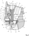
- FIG. 2 shows the connection terminal 1 from Figure 1 in the now actuated state.
- the actuating button 6 is now linearly displaced in the actuating channel 5 in the direction of the actuating axis B downwards towards the busbar 8.
- the actuating button 6 is guided in the direction of the actuating axis B on a sliding plane G formed by the partition 7.
- the clamping leg 15 of the clamping spring 11 exerts a force on the actuating button 6.
- the direction of the force is always less than 50° to the sliding plane G and is therefore essentially directed in the direction of the actuating axis B.
- the clamping leg 15 is shown in two deflection states. In the upper state, which overlaps the actuating button 6, the actuating button 6 would not penetrate into the connection opening 9 of the busbar 8.
- the plug dimension S 1 for clamping an electrical conductor would then be significantly smaller than the smallest diameter of the conically tapering conductor insertion channel 3. An electrical conductor would then hit the clamping end 16 and be guided by it into this narrow point.
- the actual deflection state of the clamping leg 15 is the further deflected with the plug-in dimension S 2 . It is clear that a plug-in dimension is achieved here that corresponds almost to the complete smallest diameter of the conically tapering conductor entry channel 3.
- the actuating pushbutton 6 dips with its actuating end 21 into the connection opening 9 of the busbar 8 with a depth T. This depth T is greater than the thickness of the busbar 8 in the area adjacent to the connection opening 9. It is clear that an electrical conductor guided by the partition 7, which is inserted into the conductor entry channel 3, is then first guided through the actuating end 21 of the actuating pushbutton 6, in order to only then reach the clamping edge 17.
- the actuating end 21 of the actuating button 6 is thus located between the free end of the partition 7 pointing into the interior of the connection terminal and the clamping leg end 16.
- the clamping edge 17 of the clamping leg 15 is thus set back from the actuating end 21 of the actuating button 6.
- the actuating end 21 slides along the clamping leg 15 in the area adjacent to the bend 20 up to the further bend to the clamping leg end 16. This means that a relatively long sliding path is used along the clamping leg 15.
- This design in conjunction with the partition 7 that extends down to adjacent to the busbar 8 and the actuating button 6 that extends without a projection in the direction of the actuating axis B and whose actuating end 21 is aligned with the actuating axis 8 ensures that the deformation forces on the actuating button 6 are minimal.
- the interaction between the actuating button 6 and the clamping spring 11 is optimal due to the long actuating stroke.
- connection opening 9 for connecting the electrical conductor and for accommodating the clamping spring 11 can still be used to accommodate the actuating button 6 due to the angular offset of the actuating axis B and the conductor insertion axis L. This makes it possible to completely actuated state to act on the clamping spring 11 at a point as far away as possible from the spring arch 13, whereby the force effects are optimized.
- actuating head 22 which widens conically towards the outside, is adapted to the head section of the actuating channel 5, which widens conically towards the outside of the insulating housing 2, in the fully depressed, actuated state.
- a step 25 on the head section together with a step 26 in the actuating channel 5 can optionally form a stop with which the displacement path of the actuating pusher 6 towards the busbar 8 is limited.
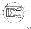
- Figure 3 omits a top view of a section of the connection terminal 1 Figure 1 in the non-actuated state. It is clear that the head section 22 has an actuating slot 23. This can also have a different shape, such as cross-shaped, square or round.
- the partition wall 7 between the conductor insertion channel 3 and the actuation channel 5, which forms a conductor channel wall 4, is curved when viewed in the cross section of the conductor insertion channel 3.
- the actuation head 22 has a curved contour adapted to this. This also applies to the section of the actuation pusher 6 adjoining the actuation head 22 and leading to the actuation end 21, which then has a constant cross section over its length.
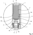
- Figure 4 shows a cross-sectional view of terminal 1 from Figure 1 in the non-actuated state as a cutout.
- the actuating button 6 in the section in the width direction of the busbar 8 in the area of the actuating head 22 has a smaller width than in an adjoining middle section 27 leading to the busbar 8.
- support surfaces 28a, 28b protrude from the contour of the actuating button 6 at the sides, which are supported on guide wall surfaces of the insulating housing 2. This support takes place in an area of the insulating housing 2 that is not so strongly influenced by the adjacent conductor entry channel 3 is weakened, as is the section of the intermediate partition wall 7 located in the central region.
- the width of the actuating section 21, seen in the cross section shown, is adapted to the width of the connection opening 9 in the busbar 8 and is at least slightly smaller than this width of the connection opening 9. In this way, it is ensured that the actuating button 6 can penetrate into the connection opening 9.
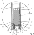
- Figure 5 shows a cross-sectional view of terminal 1 from Figure 2 in the actuated state. It is clear that the actuating end 21 dips into the connection opening 9 of the busbar 8. The shoulders 29a, 29b formed in the transition of the widened lateral support surfaces 28a, 28b of the middle section 27 to the actuating end 21 abut against the edge regions 30 of the busbar 8, which laterally delimit the connection opening 9. This prevents the actuating pusher 6 from being pressed further down into the connection opening 9.
- connection opening 90 is not aligned with the center of the actuating channel 5.
- actuating pushbutton 6 which is designed symmetrically overall, there is a gap in the actuating channel 5 between the side wall of the insulating housing 2 of the connection terminal 1 and the actuating pushbutton 6.
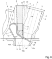
- Figure 6 shows a sectional view of another embodiment of a connection terminal 1. This is constructed in a similar way to the previously described connection terminal 1 and has only a few modifications in this respect. Essentially, reference can therefore be made to the previous description.
- the conductor entry channel 3 initially has a cylindrical casing section M, which then changes into a conically tapered section.
- the partition wall 7 in this conically tapered area forms a support and sliding surface G for the actuating button 6.
- the sliding surface G is aligned parallel to the actuating axis B.
- the partition wall 7 is pulled down so far from the upper level of the busbar 8 or the level spanned by the connection opening 9 that in the non-actuated state the clamping leg 15 is immediately adjacent to the partition wall 7, possibly with a small gap.
- the actuating head 22 has a nose 31 protruding in the direction of the conductor insertion channel 3, which in the unactuated state projects freely into the conically widening head section of the actuating channel 5.
- the actuating pusher 6 In the area adjacent to the clamping spring 11, the actuating pusher 6 is designed without projections and tapers towards the actuating end 21.
- An actuating force F is exerted by the clamping leg 15 on the clamping end 21 of the actuating pusher 6, which, as shown, is aligned at an acute angle to the sliding plane G or to the actuating axis B. This acute angle is less than 50°.
- the inner angle of the force direction F to the sliding plane G is approximately 30°.
- the actuation axis B is also arranged at an angle to the conductor insertion axis L. This angle is also approximately 15° +/- 5°.
- An angle of 16° is very suitable, with the actuating axis B being perpendicular to the plane of the busbar 8 or the plane spanned by the connection opening 9 in the busbar 8.
- Figure 7 shows the connection terminal Figure 6 in the actuated state.
- the actuating pushbutton 6 is now displaced linearly in the direction of the actuating axis B or along the sliding plane G in the image plane downwards towards the busbar, so that the tapered actuating end 21 dips into the connection opening 9 of the busbar 8.
- the clamping leg 15 of the clamping spring 11 exerts an actuating force F on the actuating end 21, which acts at an angle of less than 50° to the sliding plane G.
- the interior angle is considered.
- the force acting from the clamping leg 5 on the actuating pushbutton 6 is therefore directed in the direction of the actuating axis B rather than transversely to it.
- the direction of the force is aligned so that it points towards the partition wall 7.
- the tilting moments acting on the actuating end 21 are therefore negligible. Due to the tapered actuating end 21, which follows the direction of extension of the sliding plane G and the actuating axis B and has no projections, such disadvantageous tilting moments and deformation energies are avoided, which could impair the stability of the actuating push button 6.
- the conductor channel wall 4 While the partition wall 7 runs in a straight line towards the actuating channel 5 below the casing receiving section M, the conductor channel wall 4 has on the opposite side after a first inclined surface a further end section which essentially follows the direction of extension of the conductor channel wall 4 in the casing section M. This end section then goes into the transition of the connection opening 9 to the Connecting the busbar 8 and thus serves as an extension of the terminal wall 10c.
- the partition wall 7 to the actuating opening 5 is straight in the area of the guide section for the actuating button 6 to the busbar 8.
- the partition wall 7 has a non-uniform cross-section in this guide section and forms a wall section that conically tapers the conductor insertion channel 3 below the jacket section M.
- the end section of the conductor insertion channel 3 in the opening to the connection opening 9 in the busbar 8 changes into a cylindrical section or a section with a constant cross-section.
- Figure 8 shows a cross-sectional view of a section of an embodiment of the connection terminal 1 in the area of the actuating head 22 of the actuating pushbutton 22. It is clear that the inner wall 40 of the actuating channel 5, which is opposite the partition wall 7, is inclined towards the actuating opening at the head end of the actuating channel 5 in the direction of the partition wall 7. This leads to a tilting of the actuating pushbutton 6 in the direction of the partition wall 7 and the conductor insertion channel 3 when the actuating pushbutton 6 is returned as shown. Figures 3 and 4 The visible gap or slot between the partition wall 7 and the actuating head 22 is at least largely closed. Possible ingress of dirt and/or foreign bodies is thus prevented and the visual appearance is improved.
- the actuating head 22 is slightly thicker in the width direction than the rest of the section. This means that the actuating opening of the actuating channel 5 can be filled as far as possible in the width direction, apart from small gaps at the side.
- the actuating button 6 is slightly tilted in the actuating channel 5 in the direction in which the terminal blocks are arranged on a support rail, i.e. in the direction of the side walls. This means that the same symmetrical actuating button 6 can be used on both ends of a terminal block, and a uniform connection pattern is achieved.
- Figure 9 leaves a cross-sectional view of the section Figure 8 in section AA. It is clear that the actuating head 22 fills the actuating channel except for small remaining gaps. It is also clear that one side wall of the conductor entry channel is open at the side. An insulating sheath of an electrical conductor to be connected can penetrate into this area, taking over the insulating function of the side wall. This means that the connection terminal, e.g. in the form of a series terminal, can be constructed more narrowly.
- Figure 10 leaves a cross-sectional view of the section Figure 8 in section BB. It is clear that the actuating button 6 is significantly narrower in this section than in the area of the actuating head 22.
- the conductor insertion opening 3 is also open at the side in this area and is only closed all the way around with the insulating material sheath of the electrical conductor to be connected or with the side wall of a series terminal arranged next to it.
- Figure 11 leaves a cross-sectional view of the section Figure 8 in section CC.
- the actuating button 6 rests on the clamping leg 15 of the clamping spring in this cutting area, so that when pressed down on the clamping leg 15 it slides towards the clamping edge.
- the conductor insertion opening 3 is now tapered in this cutting area and is closed all the way around by the insulating housing 2. The stripped end of an electrical conductor to be clamped is received in this cutting area.
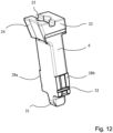
- the Figures 12 and 13 show a perspective view of the actuating button of the terminal from Figure 7 on the front and back. It can be seen that the actuating button 6 is widened in the area of the lateral support surfaces 28a, 28b. This width exceeds the width or diameter of the conductor insertion channel 3, at least when the actuating button 6 is actuated, so that the spring forces acting can be absorbed by the thicker lateral side walls. This is in Figure 11 The partition wall 7 can therefore be made thinner in the middle area, which leads to a smaller overall design of the connection terminal.
- the actuating button 6 has groove-like recesses 32 in the area of the support surfaces 28a, 28b. These can be different from one another for different variants of the actuating button 6.
- the groove-like recesses 32 are thus codes that can be detected using automated optical recognition and can be used for automated assembly.
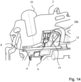
- Figure 14 shows a perspective view of the terminal 1 from Figure 8 obliquely from below. It is clear that the side wall of the conductor entry channel 3, which is open at the side, is filled by the insulating material sheath of an electrical conductor 33 to be clamped. It is also clear that the actuating button rests on the clamping leg 15 of the clamping spring 11. The support surfaces protrude laterally and rest on the insulating material housing 2.
Landscapes
- Connections Arranged To Contact A Plurality Of Conductors (AREA)
- Coupling Device And Connection With Printed Circuit (AREA)
- Installation Of Indoor Wiring (AREA)
- Details Of Connecting Devices For Male And Female Coupling (AREA)
- Installation Of Bus-Bars (AREA)
Description
- Die Erfindung betrifft eine Anschlussklemme gemäß dem Oberbegriff des Anspruchs 1.
- Unter "koaxial" wird nicht nur die Anordnung in Bezug auf eine zylinderförmige Leiterkanalwand verstanden. Wenn der Schwerpunkt eines gleichbleibenden Querschnitts der Leiterkanalwand in Erstreckungsrichtung parallel zur Leitereinführungsachse verläuft, dann ist er koaxial.
-
DE 10 2013 111 574 A1 zeigt einen Federkraftklemmanschluss zum Anklemmen elektrischer Leiter mit einem verschiebbar im Isolierstoffgehäuse aufgenommenen Betätigungsdrücker. Der Betätigungsdrücker hat eine Betätigungsfläche zur Anlage an dem Klemmschenkel der Klemmfeder, sodass der Betätigungsdrücker an dem Klemmschenkel geführt wird. Eine vorstehende Nase des Betätigungsdrückers ragt in die Ausmündung der Leitereinführungsöffnung hinein und bildet einen Teil der Wandung der Leitereinführungsöffnung. -
DE 10 2015 120 063 B3 zeigt eine Leiteranschlussklemme mit einem Isolierstoffgehäuse und einem Federkraftklemmanschluss sowie einen in einem Drückerschacht verschiebbar aufgenommenen Drücker. Der Drücker hat eine vorstehende Drückernase, die im betätigten Zustand oberhalb einer in eine Stromschiene eingebrachten Leiteraufnahmeöffnung endet. Der Drücker ist an der die Leitereinführungsrichtung definierenden Begrenzungswand der Leitereinführungsöffnung parallel zu dieser Leitereinführungsrichtung verschiebbar gelagert. - Die Isolierstoffgehäuse und Betätigungsdrücker solcher Anschlussklemmen sind aus Kunststoffmaterial hergestellt. Die auf den Betätigungsdrücker und darüber auch auf das Isolierstoffgehäuse wirkenden Kräfte können zu einer Verformung des Kunststoffmaterials führen. Dies gilt insbesondere, weil der im Bereich der Klemmfeder verfügbare Bauraum zur Unterbringung der Leitereinführungsöffnung und des Betätigungsdrückers neben der Klemmfeder und damit die verfügbare Materialstärke sehr begrenzt ist.
- Aus der
DE 10 2010 015457 A1 , die den Oberbegriff des Anspruchs 1 offenbart, ist ein Federkraftklemmanschluss und ein Klemmbauelement bekannt. Aus derEP 3 159 971 A1 ist eine Basisklemme mit einer Befestigungsstruktur bekannt. - Ausgehend hiervon ist es Aufgabe der vorliegenden Erfindung, eine verbesserte Anschlussklemme zu schaffen.
- Die Aufgabe wird mit der Anschlussklemme mit den Merkmalen des Anspruchs 1 gelöst. Vorteilhafte Ausführungsformen sind in den Unteransprüchen beschrieben.
- Für eine gattungsgemäße Anschlussklemme wird vorgeschlagen, dass die Stromschiene und der Betätigungsdrücker im Betätigungszustand, bei der der Klemmschenkel durch den Betätigungsdrücker zum Anlageschenkel hin verlagert ist, in die Anschlussöffnung hineinragt. Die zentrale Betätigungsachse des Betätigungskanals ist in Breitenrichtung der Anschlussöffnung versetzt zur Mittelachse der Anschlussöffnung. Ein in dem Betätigungskanal aufgenommener Betätigungskopf ist in Breitenrichtung dicker als der sich daran anschließende zur Anschlussöffnung führende Abschnitt des Betätigungsdrückers. Die Mitte der Anschlussöffnung in der Ebene der Stromschiene fluchtet somit nicht mit der Mitte des Betätigungskanals, so dass bei eingesetztem insgesamt symmetrisch ausgebildeten Betätigungsdrücker ein Spalt im Betätigungskanal zwischen der seitlichen Wand des Isolierstoffgehäuses der Anschlussklemme und dem Betätigungsdrücker vorhanden ist. Um nun einen solchen Spalt zu verringern und/oder zu vergleichmäßigen und zugleich an beiden Enden z.B. einer Reihenklemme dieselben symmetrischen Betätigungsdrücker spiegelverdreht zueinander, d.h. auf Umschlag zu verwenden, ist der Betätigungskopf des Betätigungsdrückers in Breitenrichtung etwas dicker als über den übrigen Abschnitt ausgebildet. Dies führt dazu, dass die Betätigungsöffnung des Betätigungskanals in Breitenrichtung bis auf kleine Spalte weitestgehend ausgefüllt ist. Der Betätigungsdrücker ist dabei im Betätigungskanal leicht gekippt in Anreihrichtung der Reihenklemme auf einer Tragschiene ausgerichtet. Diese Ausführungsform, die mit den oben beschriebenen weiteren Merkmalen der Anschlussklemme kombinierbar ist, hat ein gleichmäßiges Anschlussbild auf der Oberseite der Anschlussklemme zur Folge.
- Durch eine Ausrichtung der Betätigungsachse, die durch die Längsverschieberichtung des Betätigungsdrückers im Betätigungskanal definiert ist, relativ zur Leitereinführungsachse im Winkel von 5° bis 30° und bevorzugt 5° bis 20° wird erreicht, dass die Leitereinführungsöffnung und der Betätigungsdrücker in einem sehr kleinen Bauraum aufgenommen werden können. Der eingeführte Leiter und der Betätigungsdrücker werden dadurch auf einen gemeinsamen (virtuellen) Treffpunkt aufeinander zu in das Isolierstoffgehäuse hinein verlagert, wenn sie in einem solchen spitzen Winkel zueinander stehen. Durch den Winkelversatz gelingt es, den damit verfügbaren Raum zwischen Betätigungskanal und Leitereinführungskanal zur optimierten Abstützung des Betätigungsdrückers zu nutzen. Durch den relativen Winkelversatz zwischen der Erstreckungsrichtung des Leitereinführungskanals und der Erstreckungsrichtung des Betätigungskanals kann die auf den Betätigungsdrücker von dem Klemmschenkel der Klemmfeder einwirkende Kraftrichtung verbessert werden, um so einer Verformung des Betätigungsdrückers und damit auch des Isolierstoffgehäuses entgegenzuwirken.
- Der Winkel kann insbesondere mit einer konstruktiv angepassten Düsung größer gestaltet werden und dabei im oberen angegebenen Winkelbereich von mehr als 20° liegen. Vergleichbare konstruktive Gestaltungen sind denkbar, um die gewünschte Winkelausrichtung zu erhalten.
- Die Leiterkanalwand kann eine Trennwand zu dem Betätigungskanal bilden. Der Betätigungsdrücker ist dann in einem den Leitereinführungskanal konisch verjüngenden Abschnitt der Trennwand geführt. Dieser Abschnitt kann parallel zur Betätigungsachse ausgerichtet sein.
- Die Betätigungsachse kann in etwa lotrecht zu der durch die Anschlussöffnung aufgespannten Ebene ausgerichtet sein. Unter "in etwa lotrecht" wird insbesondere ein Winkel von 90° mit einer Toleranz von ± 5° und bevorzugt ± 2° verstanden.
- Dieser sich konisch verjüngende Abschnitt wird auf diese Weise nicht nur zum gezielten Führen eines abisolierten Endes eines anzuklemmenden elektrischen Leiters zur Klemmstelle hin genutzt, sondern stellt in dem nahe zur Klemmfeder liegenden Bereich eine Stützwand für den Betätigungsdrücker bereit. Unter dem Einfluss der ausgelenkten Klemmfeder wirken die über den Betätigungsdrücker auf den sich konisch verjüngenden Abschnitt der Trennwand ausgeübten Kraftkomponenten in einem spitzeren Winkel, als bei einer Abstützung des Betätigungsdrückers an einem sich nicht konisch verjüngenden Abschnitt der Trennwand des Leitereinführungskanals. Auf diese Weise kann die Gefahr einer plastischen oder elastischen Verformung der Trennwand reduziert werden.
- Die Stromschiene kann eine Anschlussöffnung haben, wobei die Schenkelfeder in diese Anschlussöffnung eingesetzt ist. Der Betätigungsdrücker ragt dann im Betätigungszustand, bei der der Klemmschenkel durch den Betätigungsdrücker zum Anlageschenkel hin verlagert ist, in diese Anschlussöffnung hinein.
- Mit einer solchen Anschlussöffnung, die in der Art eines Materialdurchzugs auch noch mit Führungswänden kanalartig ausgestaltet sein kann, kann ein elektrischer Leiter zuverlässig zur Klemmstelle geführt werden. Dies gilt insbesondere für mehrdrähtige elektrische Leiter, deren Litzen ansonsten aufspreizen können, wenn der Leiter ohne vorherige Auslenkung der Klemmfeder mit Hilfe des Betätigungsdrückers angeklemmt wird. Bei einer solchen Anschlussöffnung ist der verfügbare Raum zur Aufnahme des elektrischen Leiters und der Klemmfeder aber stark reduziert. Eine optimale Ausnutzung des verfügbaren geringen Platzes gelingt ohne Risiko der Verformungsgefahr durch die Ausrichtung der Betätigungsachse und Leitereinführungsachse im Winkel von 5° bis 20° zueinander. Dabei wird die Zusammenwirkung von Betätigungsdrücker und Klemmfeder wesentlich verbessert, wenn der Hub des Betätigungsdrückers zum Klemmende des Klemmschenkels hin möglichst stark ausgenutzt wird. Dies gelingt, wenn der Betätigungsdrücker in die Anschlussöffnung im betätigten Zustand eintaucht. Zwar wird dadurch der verfügbare Platz noch weiter eingeschränkt. Tatsächlich ist dieser Hubraum aber verfügbar, wenn die Betätigungsachse und die Leitereinführungsachse in dem Winkel von 5° bis 20° zueinander ausgerichtet sind. Der elektrische Leiter wird auf diese Weise vorteilhaft an dem Betätigungsdrücker entlanggeführt und stößt nicht auf dem Klemmschenkel auf.
- Der Betätigungsdrücker kann an seinem den Klemmschenkel beaufschlagenden Betätigungsende einen die Breite des Betätigungsendes verringernden Absatz aufweisen. Der Absatz bildet dann einen Anschlag zur Auflage auf einen die Anschlussöffnung begrenzenden Randbereich der Stromschiene. Dadurch, dass sich das Betätigungsende des Betätigungsdrückers verjüngt, um in die Anschlussöffnung eintauchen zu können, wird der Verschiebeweg des Betätigungsdrückers mit Hilfe des Absatzes begrenzt, der einen Anschlag zwischen Betätigungsdrücker und Stromschiene bildet. Zudem wird der Betätigungsdrücker mit Hilfe des Absatzes oberhalb des Betätigungsendes breiter gestaltet, als im Betätigungsende. Der Betätigungsdrücker ist dadurch stabiler und kann an dem verbreiterten Ende am Isolierstoffgehäuse in einem Bereich abgestützt werden, der aufgrund der in der Regel zylinderförmigen Ausführung des angrenzenden Leitereinführungskanals stärker als im zentralen Bereich ist.
- Die zu dem Klemmschenkel hin gewandte Fläche des Betätigungsdrückers kann ausgehend von dem Betätigungskopf bis zum Klemmschenkel ohne einen Vorsprung ausgebildet sein. Der Betätigungsdrücker ist mit anderen Worten im Querschnitt senkrecht zur Betätigungsachse in der Richtung von dem Leitereinführungskanal zur Klemmfeder hin gesehen ausgehend von einem Betätigungskopf vorsprungsfrei zum Klemmschenkel hin ausgebildet. Wenn das Betätigungsende somit einen in Richtung Klemmschenkel bzw. in entgegengesetzter Richtung zur Ausmündung des Leitereinführungskanals hin gleichbleibenden Querschnitt, d.h. keine Vorwölbung hat, dann wird ein mögliches Knickmoment vermieden oder zumindest reduziert, das durch die Klemmfeder auf den Betätigungsdrücker wirken kann. Zudem wird der durch den Betätigungsdrücker benötigte Raum durch die vorsprungsfreie Ausgestaltung klein gehalten.
- Die Stirnfläche des den Klemmschenkel beaufschlagenden Betätigungsendes des Betätigungsdrückers kann eine abgerundete Kontur haben. Dann ist das Betätigungsende zwar verjüngt, aber es wird durch die abgerundete Kontur immer noch kein nachteiliger Vorsprung gebildet.
- Der Betätigungskanal kann in einem Kopfabschnitt, der neben einem zylinderförmigen Mantelaufnahmeabschnitt des Leitereinführungskanals liegt, konisch zur Außenseite des Isolierstoffgehäuses hin erweitert sein. Damit hat der Betätigungsdrücker einen Betätigungskopf in dem sich konisch erweiterten Kopfabschnitt, der im Querschnitt von dem Leitereinführungskanal zur Klemmfeder hin gesehen eine zur Außenseite des Isolierstoffgehäuses hin zunehmenden Dicke hat. Der durch die Schrägstellung von Betätigungsachse und Leitereinführungsachse im Vergleich zur parallelen Ausrichtung vergrößerte Bauraum zur Außenseite hin kann genutzt werden, um einen verbreiterten Betätigungskopf realisieren zu können. Der Betätigungskanal hat dann einen an den sich konisch erweiternden Kopfabschnitt angepassten Querschnitt, durch den eine Entformung des Spritzgusswerkzeuges bei der Spritzgussherstellung des Isolierstoffgehäuses einfach und zuverlässig möglich ist.
- Durch den sich konisch nach außen hin erweiternden Kopfabschnitt wird eine Fläche zur Beaufschlagung des Betätigungsdrückers bereitgestellt, die mit handelsüblichen Schraubendrehern als Betätigungswerkzeug zuverlässig beaufschlagt werden kann.
- Der Klemmschenkel der Klemmfeder kann ausgehend vom Federbogen im unbetätigten Zustand, in dem der Klemmschenkel nicht durch den Betätigungsdrücker zum Anlageschenkel hin ausgelenkt wird, so in Bezug auf den Federbogen ausgerichtet sein, dass sich der Klemmschenkel in Erstreckungsrichtung des Betätigungsdrückers neben dem Betätigungsdrücker erstreckt und nach einer Biegung unterhalb des Betätigungsendes des unbetätigten Betätigungsdrückers in seiner Ruhestellung durch den Betätigungskanal und den Leitereinführungskanal oder durch deren Ausmündungen hindurchgeführt ist. Diese Biegung des Klemmschenkels, hinter der ausgehend vom Federbogen gesehen der Klemmschenkel unter dem Betätigungsende des Betätigungsdrückers hindurchgeführt wird, stellt den Bereich dar, an dem der Abstand zwischen Klemmschenkel und Anlageschenkel am geringsten ist. Das Betätigungsende des Betätigungsdrückers ist dann so auf den Klemmschenkel ausgerichtet, dass das Betätigungsende den sich vom Federbogen gesehen hinter der Biegung liegenden Abschnitt des Klemmschenkels beaufschlagt und bei Verschiebung des Betätigungsdrückers im Betätigungskanal an diesem Abschnitt entlanggleitet. Damit wird die Klemmfeder in dem ausgehend vom Federbogen hinter der Biegung liegenden Bereich des Klemmschenkels im Abstand vom Federbogen beaufschlagt. Damit wird sichergestellt, dass die Kraftwirkung der Klemmfeder in Bezug auf die Gleitebene des Betätigungsdrückers am Isolierstoffgehäuse bzw. in Richtung der Betätigungsachse in einem derart optimalen Winkel ist, dass die auf den Betätigungsdrücker einwirkenden Kipp- und Biegemomente und Verformungsenergien gering gehalten werden.
- Die Biegung des Klemmschenkels kann einen Innenwinkel im Bereich von 90° bis 160°, und bevorzugt bis zu 140°, haben. Damit wird sichergestellt, dass der Klemmschenkel in einem aus den oben genannten Gründen passenden Verhältnis zur Betätigungsachse bzw. zur Gleitebene des Betätigungsdrückers ausgerichtet ist.
- Der Klemmschenkel kann mit seiner Stirnkante am Klemmschenkelende die Klemmkante bilden. Ein das Klemmschenkelende sich an die Klemmkante anschließender Klemmabschnitt kann dann zur Anschlussöffnung der Stromschiene hineinweisend abgebogen sein. Durch dieses zusätzliche Abfalten des Klemmschenkels am Klemmschenkelende wird erreicht, dass der auf das Betätigungsende des Betätigungsdrückers wirkende Abschnitt des Klemmschenkels in einem größeren Winkel zur Betätigungsachse hin ausgerichtet werden kann, als dies ohne diese Abwinkelung am Klemmschenkelende möglich wäre.
- Der Klemmschenkel der Klemmfeder kann so ausgebildet sein, dass er in jedem Betätigungszustand auf den Betätigungsdrücker eine Kraft in einem Winkel von weniger als 50° zu einer Gleitebene, an der der Betätigungsdrücker längsverschiebbar geführt ist, ausübt. Damit wird sichergestellt, dass ein auf den Betätigungsdrücker einwirkendes Kippmoment sowie die Verformungsenergie möglichst gering gehalten wird.
- Die Betätigungsachse und die Leitereinführungsachse können den Klemmschenkel der Klemmfeder unabhängig voneinander an unterschiedlichen Schnittpunkten schneiden und voneinander beabstandet durch eine Anschlussöffnung in der Stromschiene hindurch verlaufen und sich erst unterhalb der Ebene der Stromschiene, welche die Anschlussöffnung aufweist, schneiden. Damit liegen der Betätigungsdrücker und der anzuklemmende Leiter nahe beieinander und sind im Winkel so zueinander ausgerichtet, dass der Betätigungsdrücker und der elektrische Leiter unabhängig voneinander an dem Klemmschenkel wirken, wobei der Betätigungsdrücker bei der Betätigung am Klemmschenkel entlanggleitet.
- Das Betätigungsende des Betätigungsdrückers kann im betätigten Zustand nahe am Klemmschenkelende bzw. nahe zur Klemmkante liegen, so dass der Anschluss insgesamt kleiner bauen kann. Im Zusammenhang mit der Tatsache, dass das Betätigungsende über einen recht langen Weg am dem Klemmschenkel entlang gleitet, lassen sich zudem die Betätigungskräfte vergleichmäßigen und somit insgesamt auch reduzieren. Die Betätigungskraft kann so über den gesamten Betätigungsweg in etwa gleich gehalten werden, was zu einem gleichmäßigen Betätigungskraftniveau führt. Damit ist auch eine sichere und gleichmäßige Rückführung des Betätigungsdrückers möglich.
- Der Betätigungsdrücker kann einen Absatz haben, der mit einem Vorsprung im Betätigungskanal einen Rücklaufanschlag in zur Betätigungsrichtung des Betätigungsdrückers entgegengesetzte Richtung bildet. Damit wird ein Herausfallen des Betätigungsdrückers aus dem Betätigungskanal verhindert. Bei der Montage wird der Betätigungsdrücker in den Betätigungskanal eingeführt, wobei sich die Seitenwände aufweiten könen, bis der Rücklaufanschlag hinter die Ausnehmung bzw. die Rastkante der Seitenwand schnappt.
- Zwischen dem Betätigungskanal und dem Leitereinführungskanal ist eine Trennwand. Die der Trennwand gegenüberliegende Begrenzungswand des Betätigungskanals ist relativ zur Betätigungsachse geneigt. Damit ist die gegenüber der Trennwand liegende Innenwandung des Betätigungskanals hin zur Betätigungsöffnung des Betätigungskanals in Richtung der Trennwand zulaufend geneigt ausgeführt. Dies führt bei der Rückführung des Betätigungsdrückers zu einer Verkippung des Betätigungsdrückers in Richtung der Trennwand bzw. des Leitereinführungskanals, so dass ein Schlitz zwischen der Trennwand und dem Kopfende verringert und vorzugsweise zumindest weitgehend geschlossen wird. Ein mögliches Eindringen von Schmutz und/oder Fremdkörpern wird somit vermieden und es wird zudem die optische Anmutung verbessert.
- Die Betätigungsdrücker können nutartige Vertiefungen haben. Diese nutartigen Vertiefungen können beispielsweise an den seitlichen Stützflächen angeordnet sein. Für verschiedenartige Betätigungsdrücker können unterschiedliche Vertiefungen vorgesehen sein. Damit ist eine Kodierung der Betätigungsdrücker zur optischen Erkennung für die automatisierte Montage möglich.
- Im Sinne der vorliegenden Erfindung ist der unbestimmte Begriff "ein" als solcher und nicht als Zahlwort zu verstehen und erfasst auch eine Mehrzahl im Sinne von "mindestens ein".
- Die Erfindung wird nachfolgend anhand eines Ausführungsbeispiels mit den beigefügten Zeichnungen näher erläutert. Es zeigen:
- Figur 1 -
- Schnittansicht einer Anschlussklemme im unbetätigten Zustand;
- Figur 2 -
- Schnittansicht der Anschlussklemme aus
Figur 1 im betätigten Zustand; - Figur 3 -
- Ausschnitt der Anschlussklemme aus
Figur 1 in der Draufsicht; - Figur 4 -
- Querschnittsansicht eines Ausschnitts der Anschlussklemme aus
Figur 1 im unbetätigten Zustand; - Figur 5 -
- Querschnittsansicht eines Ausschnitts der Anschlussklemme aus
Figur 2 im betätigten Zustand; - Figur 6 -
- Schnittansicht einer weiteren Anschlussklemme im unbetätigten Zustand;
- Figur 7 -
- Anschlussklemme aus
Figur 6 im betätigten Zustand; - Figur 8 -
- Querschnittsansicht eines Ausschnitts einer Ausführungsform der Anschlussklemme;
- Figur 9 -
- Querschnittsansicht des Ausschnitts aus
Figur 8 im Schnitt A-A; - Figur 10 -
- Querschnittsansicht des Ausschnitts aus
Figur 8 im Schnitt B-B; - Figur 11 -
- Querschnittsansicht des Ausschnitts aus
Figur 8 im Schnitt C-C; - Figur 12 -
- perspektivische Ansicht des Betätigungsdrückers der Anschlussklemme aus
Figur 7 auf die Vorderseite; - Figur 13 -
- perspektivische Ansicht des Betätigungsdrückers der Anschlussklemme aus
Figur 7 auf die Rückseite; - Figur 14 -
- Perspektivische Ansicht der Anschlussklemme aus
Figur 8 schräg von unten. -
Figur 1 zeigt eine Schnittansicht einer Anschlussklemme 1 mit einem Isolierstoffgehäuse 2. Die Anschlussklemme 1 ist in dem dargestellten Ausführungsbeispiel ein Teil einer Reihenklemme, die nur im Ausschnitt dargestellt ist und mehrere solcher Anschlussklemmen haben kann. - Das Isolierstoffgehäuse 2 hat einen Leitereinführungskanal 3, der durch umlaufende Leiterkanalwände 4 begrenzt ist. Neben dem Leitereinführungskanal 3 ist ein Betätigungskanal 5 angeordnet, in dem ein Betätigungsdrücker 6 verschiebbar gelagert ist. Die an den Betätigungskanal 5 angrenzende Leiterkanalwand 4 des Leitereinführungskanals 3 bildet eine Trennwand 7 zu dem Betätigungskanal 5.
- Die Anschlussklemme 1 hat weiterhin eine Stromschiene 8 mit einer Anschlussöffnung 9, die in die von der Stromschiene 8 aufgespannte Ebene eingebracht ist. Die Anschlussöffnung 9 ist als Materialdurchzug mit aus der Ebene der Stromschiene 8 in Einsteckrichtung eines elektrischen Leiters nach unten ragenden in Längserstreckung der Stromschiene 8 ausgerichteten seitlichen Führungswänden 10a sowie einer Anlagewand 10b und einer Kontaktwand 10c ausgebildet. Die Führungswände 10a sind einstückig aus dem Material der Stromschiene 8 ausgeformt und stellen Führungswände für einen elektrischen Leiter bereit.
- Eine U-förmig gebogene Schenkelfeder 11 ist in diese Anschlussöffnung 9 der Stromschiene 8 eingesetzt. Die Schenkelfeder 11 hat einen Anlageschenkel 12, der an einer von der Stromschiene 8 abragenden Anlagewand 10b anliegt und dort aufgelagert ist. An den Anlageschenkel 12 der Schenkelfeder 11 schließt sich ein Federbogen 13 an. Die Schenkelfeder ist in einem Freiraum des Isolierstoffgehäuses 2 aufgenommen. Der Bewegungsraum der Schenkelfeder 11 kann durch den Freiraum begrenzende Wandflächen des Isolierstoffgehäuses 2 und optional durch einen zusätzlichen Haltezapfen 14 begrenzt werden.
- An den Federbogen 13 schließt sich ein dem Anlageschenkel 12 diametral gegenüberliegender Klemmschenkel 15 an. Dieser Klemmschenkel 15 taucht mit seinem freien Klemmende in die Anschlussöffnung 9 ein. Der Klemmschenkel 15 bildet mit seiner Stirnkante am Klemmschenkelende 16 eine Klemmkante 17. Ein in den Leitereinführungskanal 3 eingeführter elektrischer Leiter kann dann zwischen der Klemmkante 17 und der Stromschiene 8 angeklemmt werden. Die Stromschiene 8 stellt hierfür eine Kontaktwand 10c bereit, die einstückig aus dem Material der Stromschiene 8 ausgeformt ist und sich schräg zur Ebene der Stromschiene 8 in die Flucht der Anschlussöffnung 9 hineinerstreckt. Diese Kontaktwand 10c ist durch eine Biegekontur so ausgebildet, dass eine vorstehende Kontaktkante 19 bereitgestellt wird und in dem dargestellten Ruhezustand ohne eingesteckten Leiter die Klemmkante 17 in der Anschlussöffnung 9 der Kontaktwand 18 anliegt.
- Der Klemmschenkel 15 hat in der Nähe des Federbogens 13 eine Biegung 20 und ist auf diese Weise so geführt, dass der Klemmschenkel 15 sich in dem dargestellten unbetätigten Zustand, in dem der Klemmschenkel 15 nicht durch den Betätigungsdrücker 6 ausgelenkt wird, ausgehend vom Federbogen 13 zunächst in Erstreckungsrichtung des Betätigungsdrückers 6 neben dem Betätigungsdrücker 6, und an die Biegung 20 anschließend unterhalb des Betätigungsendes 21 des Betätigungsdrückers 6 erstreckt. Der Klemmschenkel 15 ist auf diese Weise durch den Betätigungskanal 5 und den Leitereinführungskanal 3 bzw. durch deren Ausmündungen quer hindurchgeführt. Unter "quer" wird verstanden, dass der Klemmschenkel 15 den Betätigungskanal 5 und den Leitereinführungskanal 3 in einem Winkel von mehr als 45° schneidet und damit im Wesentlichen senkrecht hierzu ausgerichtet ist.
- Der Klemmschenkel 15 ist mit seiner Biegung 20 weiterhin so ausgeformt, dass der Abstand zwischen Klemmschenkel 15 und Anlageschenkel 12 an der Biegung am geringsten ist.
- Ferner wird deutlich, dass die Trennwand 7 in dem unbetätigten Zustand bis zum Klemmschenkel 15 heruntergeführt ist. Die Trennwand 7 muss den Klemmschenkel 15 nicht berühren, sondern kann im Abstand eines kleinen Spalts daran angrenzen. Dieser Abstand sollte jedoch möglichst klein sein und vorzugsweise geringer sein als die Dicke des Klemmschenkels 15 als Toleranzmaß. Damit wird erreicht, dass der Betätigungsdrücker 6 auch in der Nähe der Klemmfeder 11 in einem Bereich, bei dem die Kraftwirkung durch die Klemmfeder 11 auf den Betätigungsdrücker 6 und damit auf die daran anliegende Trennwand 7 am größten ist, geführt wird.
- Deutlich wird weiterhin, dass in dem nach außen führenden Bereich des Leitereinführungskanals 3 ein zylinderförmiger Mantelaufnahmeabschnitt M durch die umlaufenden Leiterkanalwände 4 geschaffen wird. Dieser Mantelaufnahmeabschnitt M kann auch ovalförmig oder mehreckig sein. Wesentlich ist nur, dass im Bereich des Mantelaufnahmeabschnitts M der Durchmesser bzw. die Querschnittsfläche über die Leitereinführungsachse L gleichbleibend ist. Die Leitereinführungsachse L wird durch die Erstreckungsrichtung des Leitereinführungskanals 3 und damit durch die konzentrisch hierzu verlaufenden Leiterkanalwände 4 festgelegt.
- An den Mantelaufnahmeabschnitt M schließt sich ein sich konisch zur Stromschiene 8 hin verjüngender Abschnitt an. Die als Zwischenwand zum Betätigungskanal 5 dienende Trennwand 7 erstreckt sich in diesem konisch zulaufenden Bereich des Leitereinführungskanals 3 in Richtung der Betätigungsachse B und ist parallel zu dieser Betätigungsachse B ausgerichtet. Die Betätigungsachse B wird durch die Erstreckungsrichtung des Betätigungsdrückers 6 und durch die hieran angepasste Form der Innenwände des Betätigungskanals 5 festgelegt, die sich konzentrisch um die Betätigungsachse B erstrecken.
- Deutlich wird, dass die Betätigungsachse B in einem Winkel zur Leitereinführungsachse L ausgerichtet ist. Der Winkel zwischen Betätigungsachse B und Leitereinführungsachse L liegt im Bereich von 5° bis 20°. In dem dargestellten Ausführungsbeispiel beträgt er etwa 15° +/- 5°.
- Deutlich wird weiterhin, dass die Betätigungsachse B in etwa lotrecht zur Ebene der Stromschiene 8 und damit zu der durch die Anschlussöffnung 9 aufgespannten Ebene ausgerichtet ist. Die Leitereinführungsachse L hat einen Innenwinkel von etwa 75° zu der Ebene der Stromschiene 8.
- Erkennbar ist weiterhin, dass der Betätigungskanal 5 in einem Kopfabschnitt, der neben dem zylinderförmigen Mantelabschnitt M liegt, konisch zur Außenseite des Isolierstoffgehäuses 2 hin erweitert ist. In diesem, sich konisch erweiternden Kopfabschnitt des Betätigungskanals 5 hat der Betätigungskopf 22 des Betätigungsdrückers 6 eine zum Kopfende hin zunehmende Dicke im Querschnitt vom Leitereinführungskanal 3 zur Klemmfeder hin gesehen, d.h. in dem dargestellten Schnitt.
- An dem Kopfende des Betätigungsdrückers 6 ist ein Betätigungsschlitz 23 oder eine anderweitige Ausnehmung vorhanden, der zur Aufnahme des Endes eines Betätigungswerkzeuges vorgesehen ist.
- Die Trennwand 7 zwischen Leitereinführungskanal 3 und Betätigungskanal 5 hat an ihrem äußeren Ende einen Lappen 24. Dieser entsteht nach Entformung eines aus dem Leitereinführungskanal 3 und Betätigungskanal 5 herausgezogenen Spritzgusswerkzeugteils durch elastische Verformung.
-
Figur 2 zeigt die Anschlussklemme 1 ausFigur 1 in dem nun betätigten Zustand. Deutlich wird, dass nun der Betätigungsdrücker 6 in dem Betätigungskanal 5 in Richtung der Betätigungsachse B nach unten zur Stromschiene 8 hin linear verschoben ist. Dabei wird der Betätigungsdrücker 6 an einer durch die Trennwand 7 gebildeten Gleitebene G in Richtung der Betätigungsachse B geführt. Während der Betätigung des Betätigungsdrückers 6, d.h. des Herunterdrückens in Richtung Stromschiene 8 übt der Klemmschenkel 15 der Klemmfeder 11 eine Kraft auf den Betätigungsdrücker 6 aus. Die Kraftrichtung ist dabei immer kleiner als 50° zur Gleitebene G und damit im Wesentlichen in Richtung der Betätigungsachse B hin gerichtet. Der Einfluss von Querkräften, die auf den Betätigungsdrücker 6 wirken, ist damit erheblich reduziert. Hinzu kommt, dass die sehr weit nach unten zur Stromschiene 8 gezogene Trennwand 7 solche Querkräfte und daraus resultierende Kippmomente auffangen kann. Die von der Klemmfeder 11 auf den Betätigungsdrücker 6 wirkenden Kräfte sind in jedem Betätigungszustand auf die Trennwand 7 gerichtet und nicht auf einen Bereich des Betätigungsdrückers 6, der nicht durch das Isolierstoffgehäuse 2 abgestützt ist. - Der Klemmschenkel 15 ist in zwei Auslenkungszuständen dargestellt. In dem oberen, den Betätigungsdrücker 6 überschneidenden Zustand würde der Betätigungsdrücker 6 nicht in die Anschlussöffnung 9 der Stromschiene 8 eintauchen. Dann wäre das Steckmaß S1 zum Anklemmen eines elektrischen Leiters wesentlich geringer, als der kleinste Durchmesser des sich konisch verjüngenden Leitereinführungskanals 3. Ein elektrischer Leiter würde dann an das Klemmende 16 anstoßen und von diesem in diese Engstelle geführt werden.
- Der tatsächliche Auslenkzustand des Klemmschenkels 15 ist der weiter ausgelenkte mit dem Steckmaß S2. Deutlich wird, dass hier ein Steckmaß erreicht wird, dass nahezu dem vollständigen kleinsten Durchmesser des sich konisch verjüngenden Leitereinführungskanals 3 entspricht. In diesem Zustand taucht der Betätigungsdrücker 6 mit seinem Betätigungsende 21 in die Anschlussöffnung 9 der Stromschiene 8 mit einer Tiefe T ein. Diese Tiefe T ist größer als die Dicke der Stromschiene 8 in dem die Anschlussöffnung 9 anschließenden Bereich. Deutlich wird, dass ein von der Trennwand 7 geführter elektrischer Leiter, der in den Leitereinführungskanal 3 eingesteckt wird, anschließend zunächst einmal durch das Betätigungsende 21 des Betätigungsdrückers 6 geführt wird, um sodann erst zur Klemmkante 17 zu gelangen. Das Betätigungsende 21 des Betätigungsdrückers 6 liegt somit zwischen dem in den Innenraum der Anschlussklemme weisenden freien Ende der Trennwand 7 und dem Klemmschenkelende 16. Die Klemmkante 17 des Klemmschenkels 15 ist somit gegenüber dem Betätigungsende 21 des Betätigungsdrückers 6 zurückversetzt.
- Deutlich wird weiterhin, dass der geringste Abstand des Klemmschenkels 15 zum Anlageschenkel 12 auch im betätigten Zustand zumindest auch im Bereich der Biegung 20 vorhanden ist.
- Bei der Betätigung des Betätigungsdrückers 6 gleitet das Betätigungsende 21 an dem Klemmschenkel 15 in dem sich an die Biegung 20 anschließenden Bereich bis hin zur weiteren Umbiegung zum Klemmschenkelende 16 hin ab. Damit wird ein relativ langer Gleitweg an dem Klemmschenkel 15 entlang genutzt. Diese Ausgestaltung in Verbindung mit der sich bis benachbart zur Stromschiene 8 heruntergezogenen Trennwand 7 und dem sich ohne Vorsprung in Richtung der Betätigungsachse B erstreckenden und mit seinem Betätigungsende 21 in der Flucht der Betätigungsachse 8 wirksamen Betätigungsdrückers 6 wird erreicht, dass die Verformungskräfte auf den Betätigungsdrücker 6 minimal sind. Zudem ist die Zusammenwirkung zwischen Betätigungsdrücker 6 und Klemmfeder 11 durch den langen Betätigungshub optimal. Der geringe verfügbare Raum in der Anschlussöffnung 9 zum Anklemmen des elektrischen Leiters und zur Aufnahme der Klemmfeder 11 kann durch den Winkelversatz von Betätigungsachse B und Leitereinführungsachse L weiterhin zur Aufnahme des Betätigungsdrückers 6 genutzt werden. Damit gelingt es im vollständig betätigten Zustand in einem möglichst weit vom Federbogen 13 entfernten Punkt auf die Klemmfeder 11 einzuwirken, wodurch die Kraftwirkungen optimiert sind.
- Es wird weiterhin deutlich, dass der sich nach außen hin konisch erweiternde Betätigungskopf 22 im vollständig heruntergedrückten, betätigten Zustand an den sich konisch zur Außenseite des Isolierstoffgehäuses 2 hin erweiternden Kopfabschnitt des Betätigungskanals 5 angepasst ist. Dabei kann optional eine Stufe 25 am Kopfabschnitt zusammen mit einer Stufe 26 im Betätigungskanal 5 einen Anschlag bilden, mit dem der Verschiebeweg des Betätigungsdrückers 6 zur Stromschiene 8 hin begrenzt ist.
-
Figur 3 lässt eine Draufsicht auf einen Ausschnitt der Anschlussklemme 1 ausFigur 1 im unbetätigten Zustand erkennen. Deutlich wird, dass der Kopfabschnitt 22 einen Betätigungsschlitz 23 hat. Dieser kann auch eine andere Form, wie z.B. kreuzförmig, eckig oder rund haben. - Deutlich wird weiterhin, dass die eine Leiterkanalwand 4 bildende Trennwand 7 zwischen dem Leitereinführungskanal 3 und dem Betätigungskanal 5 im Querschnitt des Leitereinführungskanals 3 betrachtet gekrümmt ist. Der Betätigungskopf 22 hat eine hieran angepasste gekrümmte Kontur. Dies gilt auch für den sich an den Betätigungskopf 22 anschließenden, zum Betätigungsende 21 hin führenden Abschnitt des Betätigungsdrückers 6, der dann über seine Länge einen gleichbleibenden Querschnitt hat.
-
Figur 4 zeigt eine Querschnittsansicht der Anschlussklemme 1 ausFigur 1 im unbetätigten Zustand als Ausschnitt. Dabei wird erkennbar, dass der Betätigungsdrücker 6 in dem Schnitt in Breitenrichtung der Stromschiene 8 im Bereich des Betätigungskopfes 22 eine geringere Breite hat, als in einem sich daran anschließenden, zur Stromschiene 8 hin führenden Mittelabschnitt 27. In diesem Mittelabschnitt 27 stehen seitlich Stützflächen 28a, 28b aus der Kontur des Betätigungsdrückers 6 hervor, die an Führungswandflächen des Isolierstoffgehäuses 2 aufgelagert sind. Diese Auflagerung erfolgt in einem Bereich des Isolierstoffgehäuses 2, der nicht so stark durch den benachbarten Leitereinführungskanal 3 geschwächt ist, wie der im zentralen Bereich liegende Abschnitt der zwischenliegenden Trennwand 7. - Erkennbar ist weiterhin, dass der Betätigungsdrücker 6 an seinem den Klemmschenkel 15 beaufschlagenden Betätigungsende 21 einen in die Breite des Betätigungsendes 21 im Vergleich zum Mittelabschnitt 27 und dem Betätigungskopf 22 verringernden Absatz 29a, 29b aufweist. Dieser Absatz 29a, 29b bildet einen Anschlag zur Auflage auf einen die Anschlussöffnung 9 begrenzenden Randbereich 30 der Stromschiene 8.
- Die Breite des Betätigungsabschnitts 21 in dem dargestellten Querschnitt gesehen ist an die Breite der Anschlussöffnung 9 in der Stromschiene 8 angepasst und zumindest geringfügig geringer als diese Breite der Anschlussöffnung 9. Auf diese Weise wird sichergestellt, dass der Betätigungsdrücker 6 in die Anschlussöffnung 9 eintauchen kann.
-
Figur 5 zeigt eine Querschnittsansicht der Anschlussklemme 1 ausFigur 2 im betätigten Zustand. Hierbei wird deutlich, dass das Betätigungsende 21 in die Anschlussöffnung 9 der Stromschiene 8 eintaucht. Die im Übergang der verbreiterten seitlichen Stützflächen 28a, 28b des Mittelabschnitts 27 zum Betätigungsende 21 gebildeten Absätze 29a, 29b stoßen dabei an die Randbereiche 30 der Stromschiene 8 an, welche die Anschlussöffnung 9 seitlich begrenzen. Dabei wird ein weiteres Herunterdrücken des Betätigungsdrückers 6 in die Anschlussöffnung 9 hinein verhindert. - Aus den
Figuren 4 und5 wird weiterhin deutlich, dass die Mitte der Anschlussöffnung 90 nicht mit der Mitte des Betätigungskanals 5 fluchtet. Bei dem eingesetzten, insgesamt symmetrisch ausgebildeten Betätigungsdrücker 6 ist ein Spalt im Betätigungskanal 5 zwischen der seitlichen Wand des Isolierstoffgehäuses 2 der Anschlussklemme 1 und dem Betätigungsdrücker 6 vorhanden. -
Figur 6 lässt eine Schnittansicht einer weiteren Ausführungsform einer Anschlussklemme 1 erkennen. Diese ist im Aufbau vergleichbar zur vorher beschriebenen Anschlussklemme 1 ausgeführt und hat diesbezüglich nur einige Abwandlungen. Im Wesentlichen kann daher auf die vorhergehende Beschreibung verwiesen werden. - Deutlich wird, dass auch hier der Leitereinführungskanal 3 zunächst einen zylinderförmigen Mantelabschnitt M hat, der dann in einen sich konisch verjüngenden Abschnitt übergeht. Die Trennwand 7 in diesem sich konisch verjüngenden Bereich bildet dabei eine Auflage- und Gleitfläche G für den Betätigungsdrücker 6. Die Gleitfläche G ist parallel zur Betätigungsachse B ausgerichtet. Auch hier ist die Trennwand 7 so weit von der oberen Ebene der Stromschiene 8 bzw. der durch die Anschlussöffnung 9 aufgespannten Ebene heruntergezogen, dass im unbetätigten Zustand der Klemmschenkel 15 unmittelbar benachbart zur Trennwand 7 gegebenenfalls mit einem kleinen Spalt beabstandet ist.
- In diesem Ausführungsbeispiel hat der Betätigungskopf 22 eine in Richtung Leitereinführungskanal 3 vorstehende Nase 31, die im unbetätigten Zustand frei in den sich konisch verbreiternden Kopfabschnitt des Betätigungskanals 5 hineinragt.
- In dem an die Klemmfeder 11 angrenzenden Bereich ist der Betätigungsdrücker 6 vorsprungsfrei ausgeführt und verjüngt sich zum Betätigungsende 21 hin. Von dem Klemmschenkel 15 wird eine Betätigungskraft F auf das Klemmende 21 des Betätigungsdrückers 6 ausgeübt, die wie dargestellt in einem spitzen Winkel zur Gleitebene G bzw. zur Betätigungsachse B ausgerichtet ist. Dieser spitze Winkel beträgt weniger als 50°. In dem dargestellten unbetätigten Zustand beträgt der Innenwinkel der Kraftrichtung F zur Gleitebene G etwa 30°.
- Auch bei diesem Ausführungsbeispiel ist die Betätigungsachse B in einem Winkel zur Leitereinführungsachse L versetzt angeordnet. Dieser Winkel beträgt auch hier etwa 15° +/- 5°.
- Sehr geeignet ist ein Winkel von 16°, wobei die Betätigungsachse B lotrecht zur Ebene der Stromschiene 8 bzw. der durch die Anschlussöffnung 9 in der Stromschiene 8 aufgespannten Ebene steht.
-
Figur 7 zeigt die Anschlussklemme ausFigur 6 im betätigten Zustand. Dabei ist der Betätigungsdrücker 6 nun linear in Richtung der Betätigungsachse B bzw. entlang der Gleitebene G in der Bildebene nach unten zur Stromschiene hin verschoben, sodass sich das verjüngende Betätigungsende 21 in die Anschlussöffnung 9 der Stromschiene 8 eintaucht. Dabei übt der Klemmschenkel 15 der Klemmfeder 11 eine Betätigungskraft F auf das Betätigungsende 21 aus, die in einem Winkel von weniger als 50° zur Gleitebene G hin wirkt. Auch hier wird der Innenwinkel betrachtet. Die von dem Klemmschenkel 5 auf den Betätigungsdrücker 6 wirkende Kraft ist damit eher in Richtung der Betätigungsachse B, als quer hierzu gerichtet. Die Kraftrichtung ist dabei so ausgerichtet, dass sie zur Trennwand 7 hin weist. Die auf das Betätigungsende 21 wirkenden Kippmomente sind damit vernachlässigbar. Aufgrund des sich verjüngenden Betätigungsendes 21, das der Erstreckungsrichtung der Gleitebene G und der Betätigungsachse B folgt und keine Vorsprünge aufweist, werden solche nachteiligen Kippmomente und Verformungsenergien vermieden, die die Stabilität des Betätigungsdrückers 6 beeinträchtigen könnten. - In beiden Ausführungsbeispielen wird deutlich, dass die der Trennwand 7 gegenüberliegende Leiterkanalwand 4 über den Mantelaufnahmeabschnitt M hinaus zunächst ohne Schrägfläche geführt ist. Die sich dort anschließende, zur konischen Verjüngung des Leitereinführungskanals 3 führende Schrägfläche liegt unterhalb des Mantelaufnahmeabschnitts M in Leitereinsteckrichtung zur Stromschiene 8 hin gesehen.
- Während die Trennwand 7 zum Betätigungskanal 5 hin unterhalb des Mantelaufnahmeabschnitts M gradlinig verläuft, hat die Leiterkanalwand 4 auf der gegenüberliegenden Seite nach einer ersten Schrägfläche einen weiteren Endabschnitt, der im Wesentlichen der Erstreckungsrichtung der Leiterkanalwand 4 im Mantelabschnitt M folgt. Dieser Endabschnitt geht dann in den Übergang der Anschlussöffnung 9 zum Anschließen der Stromschiene 8 über und dient somit als Verlängerung der Klemmwand 10c.
- In dem ersten Ausführungsbeispiel hingegen ist die Trennwand 7 zur Betätigungsöffnung 5 im Bereich des Führungsabschnitts für den Betätigungsdrücker 6 zur Stromschiene 8 hin gradlinig. Die Trennwand 7 hat in diesem Führungsabschnitt aber einen ungleichförmigen Querschnitt und bildet unterhalb des Mantelabschnitts M einen den Leitereinführungskanal 3 konisch verjüngenden Wandabschnitt aus. Anschließend an diese konische Verjüngung des Leitereinführungskanals 3 geht der Endabschnitt des Leitereinführungskanals 3 in der Ausmündung zur Anschlussöffnung 9 in der Stromschiene 8 in einen zylinderförmigen Abschnitt bzw. einen Abschnitt mit gleichbleibenden Querschnitt über.
-
Figur 8 zeigt eine Querschnittsansicht eines Ausschnitts einer Ausführungsform der Anschlussklemme 1 im Bereich des Betätigungskopfes 22 des Betätigungsdrückers 22 erkennen. Deutlich wird, dass die gegenüber der Trennwand 7 liegende Innenwandung 40 des Betätigungskanals 5 zur Betätigungsöffnung am Kopfende des Betätigungskanals 5 hin in Richtung zur Trennwand 7 geneigt ausgeführt ist. Dies führt bei der dargestellten Rückführung des Betätigungsdrückers 6 zu einer Verkippung des Betätigungsdrückers 6 in Richtung zur Trennwand 7 und dem Leitereinführungskanal 3. Damit wird der inFiguren 3 und4 erkennbare Spalt oder Schlitz zwischen der Trennwand 7 und dem Betätigungskopf 22 zumindest weitgehend geschlossen. Ein mögliches Eindringen von Schmutz und/oder Fremdkörpern wird somit vermieden und die optische Anmutung wird verbessert. - Deutlich wird, dass der Betätigungskopf 22 in Breitenrichtung etwas dicker ausgebildet ist, als über den übrigen Abschnitt. Damit kann die Betätigungsöffnung des Betätigungskanals 5 in Breitenrichtung bis auf kleine seitliche Spalte weitestgehend ausgefüllt werden. Der Betätigungsdrücker 6 ist dabei im Betätigungskanal 5 leicht gekippt in Anreihrichtung der Reihenklemme auf einer Tragschiene, d.h. in Richtung zu den Seitenwänden hin, ausgerichtet. Damit kann an beiden Enden einer Reihenklemme jeweils der gleiche symmetrische Betätigungsdrücker 6 auf Umschlag verwendet werden und es wird ein gleichmäßiges Anschlussbild erreicht.
-
Figur 9 lässt eine Querschnittsansicht des Ausschnitts ausFigur 8 im Schnitt A-A erkennen. Dabei wird deutlich, dass der Betätigungskopf 22 den Betätigungskanal bis auf kleine verbleibende Spalte ausfüllt. Deutlich wird auch, dass eine Seitenwand des Leitereinführungskanals seitlich geöffnet ist. In diesen Bereich kann ein Isolierstoffmantel eines anzuklemmenden elektrischen Leiters eintauchen, der die isolierende Funktion der Seitenwand übernimmt. Damit kann die Anschlussklemme, bspw. in Form einer Reihenklemme, schmaler aufgebaut sein. -
Figur 10 lässt eine Querschnittsansicht des Ausschnitts ausFigur 8 im Schnitt B-B erkennen. Deutlich wird, dass der Betätigungsdrücker 6 in diesem Schnitt deutlich schmaler als im Bereich des Betätigungskopfes 22 ist. Die Leitereinführungsöffnung 3 ist auch in diesem Bereich seitlich geöffnet und wird erst mit dem Isolierstoffmantel des anzuklemmenden elektrischen Leiters oder mit der Seitenwand einer daneben angeordneten Reihenklemme umlaufend geschlossen. -
Figur 11 lässt eine Querschnittsansicht des Ausschnitts ausFigur 8 im Schnitt C-C erkennen. Der Betätigungsdrücker 6 liegt in diesem Schnittbereich an dem Klemmschenkel 15 der Klemmfeder an, um bei Herunterdrücken an dem Klemmschenkel 15 zur Klemmkante hin abzugleiten. Die Leitereinführungsöffnung 3 ist in diesem Schnittbereich nun verjüngt und umlaufend durch das Isolierstoffgehäuse 2 geschlossen. In diesem Schnittbereich wird das abisolierte Ende eines anzuklemmenden elektrischen Leiters aufgenommen. - Die
Figuren 12 und13 zeigen eine perspektivische Ansicht des Betätigungsdrückers der Anschlussklemme ausFigur 7 auf die Vorderseite und Rückseite. Erkennbar ist, dass der Betätigungsdrücker 6 im Bereich der seitlichen Stützflächen 28a, 28b verbreitert ist. Diese Breite überragt zumindest im betätigten Zustand des Betätigungsdrückers 6 die Breite bzw. den Durchmesser des Leitereinführungskanals 3, so dass die einwirkenden Federkräfte von den dickeren seitlichen Seitenwänden aufgenommen werden können. Dies ist inFigur 11 angedeutet. Die Trennwand 7 kann dadurch im mittleren Bereich dünner ausgeführt werden, was insgesamt zu einer kleineren Ausführung der Anschlussklemme führt. - Es ist weiterhin erkennbar, dass der Betätigungsdrücker 6 im Bereich der Stützflächen 28a, 28b nutartige Vertiefungen 32 aufweist. Diese können für unterschiedliche Varianten des Betätigungsdrückers 6 unterschiedlich voneinander sein. Die nutartigen Vertiefungen 32 sind somit Kodierungen, die mit Hilfe einer automatisierten optischen Erkennung erfassbar sind und für eine automatisierte Montage genutzt werden können.
-
Figur 14 zeigt eine perspektivische Ansicht der Anschlussklemme 1 ausFigur 8 schräg von unten. Deutlich wird, dass die seitlich geöffnete Seitenwand des Leitereinführungskanals 3 durch den Isolierstoffmantel eines anzuklemmenden elektrischen Leiters 33 ausgefüllt wird. Erkennbar ist weiterhin, dass der Betätigungsdrücker an dem Klemmschenkel 15 der Klemmfeder 11 anliegt. Die Stützflächen ragen seitlich heraus und liegen an dem Isolierstoffgehäuse 2 an.
Claims (19)
- Anschlussklemme (1) mit- einem Isolierstoffgehäuse (2), das einen Leitereinführungskanal (3), der sich in Richtung einer Leitereinführachse (L) mit einer koaxial zu der Leitereinführungsachse (L) angeordneten, zumindest teilweise umlaufenden Leiterkanalwand (4) erstreckt, und einem neben dem Leitereinführungskanal (3) angeordneten Betätigungskanal (5) hat,- einer U-förmig gebogenen Schenkelfeder (11), die einen Anlageschenkel (12), einen Klemmschenkel (15) und einen den Anlageschenkel (12) mit dem Klemmschenkel (15) verbindenden Federbogen (13) hat,- einer Stromschiene (8) mit einer Anschlussöffnung (9) und- einem längsverschiebbar in dem Betätigungskanal (5) aufgenommenen Betätigungsdrücker (6),wobei die Schenkelfeder (11) in die Anschlussöffnung (9) eingesetzt ist, der Anlageschenkel (12) an der Stromschiene (8) gelagert ist und eine Klemmkante (17) des Klemmschenkels (15) mit einem Kontaktbereich der Stromschiene (8) einen Federklemmanschluss zum Anklemmen eines in den Leitereinführungskanal (3) eingesteckten elektrischen Leiters bildet, wobei der Betätigungsdrücker (6) im Betätigungszustand, bei der der Klemmschenkel (15) durch den Betätigungsdrücker (6) zum Anlageschenkel (12) hin verlagert ist, in die Anschlussöffnung (9) hineinragt,dadurch gekennzeichnet, dass die durch die Längsverschieberichtung des Betätigungsdrückers (6) im Betätigungskanal (5) definierte zentrale Betätigungsachse (B) des Betätigungskanals (5) in Breitenrichtung der Anschlussöffnung (9) versetzt zur Mittelachse der Anschlussöffnung (9) ist und ein in dem Betätigungskanal (5) aufgenommener Betätigungskopf (22) in Breitenrichtung dicker als der sich daran anschließende zur Anschlussöffnung (9) führende Abschnitt des Betätigungsdrückers (6) ist, wobei der Betätigungsdrücker (6) insofern insgesamt symmetrisch ausgebildet ist, dass an beiden Enden einer Reihenklemme dieselben symmetrischen Betätigungsdrücker (6) spiegelverdreht zueinander verwendbar sind.
- Anschlussklemme (1) nach Anspruch 1, dadurch gekennzeichnet, dass der Betätigungsdrücker (6) vom Betätigungskopf (22) zum Betätigungsende (21) im Querschnitt in Breitenrichtung der Anschlussöffnung (9) gesehen verkippt zur Öffnungsebene der Anschlussöffnung (9) in dem Betätigungskanal (5) ausgerichtet ist.
- Anschlussklemme (1) nach einem der vorhergehenden Ansprüche, dadurch gekennzeichnet, dass die Betätigungsachse (B) in etwa lotrecht zu der durch die Anschlussöffnung (9) aufgespannten Ebene ausgerichtet ist.
- Anschlussklemme (1) nach Anspruch 3, dadurch gekennzeichnet, dass die Leiterkanalwand (4) eine Trennwand (7) zu dem Betätigungskanal (5) bildet und der Betätigungsdrücker (6) in einem den Leitereinführungskanal (3) konisch verjüngenden und parallel zur Betätigungsachse (B) ausgerichteten Abschnitt der Trennwand (7) geführt ist.
- Anschlussklemme (1) nach einem der vorhergehenden Ansprüche, dadurch gekennzeichnet, dass die Betätigungsachse (B) und die Leitereinführungsachse (L) im Winkel von 5° bis 30° zueinander ausgerichtet sind.
- Anschlussklemme (1) nach Anspruch 5, dadurch gekennzeichnet, dass die Betätigungsachse (B) und die Leitereinführungsachse (L) im Winkel von 5° bis 20° zueinander ausgerichtet sind.
- Anschlussklemme (1) nach einem der vorhergehenden Ansprüche, dadurch gekennzeichnet, dass der Betätigungsdrücker (6) an seinem den Klemmschenkel (15) beaufschlagenden Betätigungsende (21) einen die Breite des Betätigungsendes (21) verringernden Absatz (29a, 29b) aufweist, wobei der Absatz (29a, 29b) einen Anschlag zur Auflage auf einen die Anschlussöffnung (9) begrenzenden Randbereich (30) der Stromschiene (8) bildet.
- Anschlussklemme (1) nach einem der vorhergehenden Ansprüche, dadurch gekennzeichnet, dass die zu dem Klemmschenkel (15) hin gewandte Fläche des Betätigungsdrückers (6) ausgehend von einem Betätigungskopf (22) bis zum Klemmschenkel (15) ohne einen Vorsprung ausgebildet ist.
- Anschlussklemme (1) nach einem der vorhergehenden Ansprüche, dadurch gekennzeichnet, dass die Stirnfläche des den Klemmschenkel (15) beaufschlagenden Betätigungsendes (21) des Betätigungsdrückers (6) eine abgerundete Kontur hat.
- Anschlussklemme (1) nach einem der vorhergehenden Ansprüche, dadurch gekennzeichnet, dass sich der Betätigungskanal (5) in einem Kopfabschnitt, der neben einem zylinderförmigen Mantelaufnahmeabschnitt (M) des Leitereinführungskanals (3) liegt, konisch zur Außenseite des Isolierstoffgehäuses (2) hin erweitert.
- Anschlussklemme (1) nach Anspruch 10, dadurch gekennzeichnet, dass der Betätigungsdrücker (6) einen Betätigungskopf (22) in dem sich konisch erweiternden Kopfabschnitt hat, wobei der Betätigungskopf (22) im Querschnitt senkrecht zur Betätigungsachse (B) gesehen eine zur Außenseite des Isolierstoffgehäuses (2) hin zunehmenden Dicke hat.
- Anschlussklemme (1) nach einem der vorhergehenden Ansprüche, dadurch gekennzeichnet, dass sich der Klemmschenkel (15) ausgehend vom Federbogen (13) im unbetätigten Zustand, in dem der Klemmschenkel (15) nicht durch den Betätigungsdrücker (6) zum Anlageschenkel (12) hin ausgelenkt wird, in Erstreckungsrichtung des Betätigungsdrückers (6) neben dem Betätigungsdrücker (6) erstreckt und nach einer Biegung (20) unterhalb des Betätigungsendes (21) des unbetätigten Betätigungsdrückers (6) in seiner Ruhestellung durch den Betätigungskanal (5) und den Leitereinführungskanal (3) oder deren Ausmündungen hindurchgeführt ist, wobei der Abstand zwischen Klemmschenkel (15) und Anlageschenkel (12) an der Biegung (20) am geringsten ist und das Betätigungsende (21) den sich vom Federbogen (13) gesehen hinter der Biegung (20) liegenden Abschnitt des Klemmschenkels (15) beaufschlagt und bei Verschiebung des Betätigungsdrückers (6) im Betätigungskanal (5) an diesem Abschnitt entlanggleitet.
- Anschlussklemme (1) nach Anspruch 12, dadurch gekennzeichnet, dass die Biegung (20) einen Innenwinkel im Bereich von 90° bis 160° hat.
- Anschlussklemme (1) nach einem der vorhergehenden Ansprüche, dadurch gekennzeichnet, dass der Klemmschenkel (15) mit seiner Stirnkante am Klemmschenkelende (16) die Klemmkante (17) bildet, wobei ein das Klemmschenkelende (16) mit der Klemmkante (17) aufweisender Klemmabschnitt zur Anschlussöffnung (9) der Stromschiene (8) hinweisend abgebogen ist.
- Anschlussklemme (1) nach einem der vorhergehenden Ansprüche, dadurch gekennzeichnet, dass der Klemmschenkel (15) in jedem Betätigungszustand auf den Betätigungsdrücker (6) eine Kraft in einem Winkel von weniger als 50° zu einer Gleitebene (G), an der der Betätigungsdrücker (6) längsverschiebbar geführt ist, ausübt.
- Anschlussklemme (1) nach einem der vorhergehenden Ansprüche, dadurch gekennzeichnet, dass die Betätigungsachse (B) und die Leitereinführungsachse (L) den Klemmschenkel (15) der Klemmfeder (11) unabhängig voneinander an unterschiedlichen Schnittpunkten schneiden und voneinander beabstandet durch eine Anschlussöffnung (9) in der Stromschiene (8) hindurch verlaufen und sich unterhalb der Ebene der Stromschiene (8), welche die Anschlussöffnung (9) aufweist, schneiden.
- Anschlussklemme (1) nach einem der vorhergehenden Ansprüche, dadurch gekennzeichnet, dass der Betätigungsdrücker (6) einen Absatz hat, der mit einem Vorsprung im Betätigungskanal (5) einen Rücklaufanschlag in zur Betätigungsrichtung des Betätigungsdrückers (6) entgegengesetzter Richtung bildet.
- Anschlussklemme (1) nach einem der vorhergehenden Ansprüche, dadurch gekennzeichnet, dass zwischen dem Betätigungskanal (5) und dem Leitereinführungskanal (3) eine Trennwand (7) ist und die der Trennwand (7) gegenüberliegende Begrenzungswand des Betätigungskanals (5) relativ zur Betätigungsachse (B) geneigt ist.
- Anschlussklemme (1) nach einem der vorhergehenden Ansprüche, dadurch gekennzeichnet, dass der Betätigungsdrücker (6) nutartige Vertiefungen (32) hat.
Applications Claiming Priority (3)
| Application Number | Priority Date | Filing Date | Title |
|---|---|---|---|
| DE102017109694.9A DE102017109694B4 (de) | 2017-05-05 | 2017-05-05 | Anschlussklemme |
| EP18721327.7A EP3619773B2 (de) | 2017-05-05 | 2018-04-25 | Anschlussklemme |
| PCT/EP2018/060594 WO2018202504A1 (de) | 2017-05-05 | 2018-04-25 | Anschlussklemme |
Related Parent Applications (2)
| Application Number | Title | Priority Date | Filing Date |
|---|---|---|---|
| EP18721327.7A Division-Into EP3619773B2 (de) | 2017-05-05 | 2018-04-25 | Anschlussklemme |
| EP18721327.7A Division EP3619773B2 (de) | 2017-05-05 | 2018-04-25 | Anschlussklemme |
Publications (3)
| Publication Number | Publication Date |
|---|---|
| EP3731346A1 EP3731346A1 (de) | 2020-10-28 |
| EP3731346B1 true EP3731346B1 (de) | 2024-09-11 |
| EP3731346C0 EP3731346C0 (de) | 2024-09-11 |
Family
ID=62091861
Family Applications (3)
| Application Number | Title | Priority Date | Filing Date |
|---|---|---|---|
| EP18721327.7A Active EP3619773B2 (de) | 2017-05-05 | 2018-04-25 | Anschlussklemme |
| EP20180556.1A Active EP3731346B1 (de) | 2017-05-05 | 2018-04-25 | Anschlussklemme |
| EP21176618.3A Pending EP3890118A1 (de) | 2017-05-05 | 2018-04-25 | Anschlussklemme |
Family Applications Before (1)
| Application Number | Title | Priority Date | Filing Date |
|---|---|---|---|
| EP18721327.7A Active EP3619773B2 (de) | 2017-05-05 | 2018-04-25 | Anschlussklemme |
Family Applications After (1)
| Application Number | Title | Priority Date | Filing Date |
|---|---|---|---|
| EP21176618.3A Pending EP3890118A1 (de) | 2017-05-05 | 2018-04-25 | Anschlussklemme |
Country Status (9)
| Country | Link |
|---|---|
| US (1) | US10615519B2 (de) |
| EP (3) | EP3619773B2 (de) |
| JP (2) | JP7220671B2 (de) |
| KR (1) | KR102593781B1 (de) |
| CN (2) | CN110622358B (de) |
| DE (2) | DE102017109694B4 (de) |
| PL (1) | PL3619773T5 (de) |
| RU (1) | RU2755182C2 (de) |
| WO (1) | WO2018202504A1 (de) |
Families Citing this family (5)
| Publication number | Priority date | Publication date | Assignee | Title |
|---|---|---|---|---|
| DE102019106353B4 (de) * | 2019-03-13 | 2023-05-25 | Phoenix Contact Gmbh & Co. Kg | Leiteranschlussklemme mit einem Betätigungselement mit angepasster Druckfläche |
| BE1027120B1 (de) | 2019-03-13 | 2020-10-14 | Phoenix Contact Gmbh & Co | Leiteranschlussklemme mit einem Betätigungselement mit angepasster Druckfläche |
| DE102020119372B4 (de) | 2020-07-22 | 2023-12-07 | WAGO Verwaltungsgesellschaft mit beschränkter Haftung | Leiteranschlussklemme |
| DE102020123282A1 (de) * | 2020-09-07 | 2022-03-10 | Phoenix Contact Gmbh & Co. Kg | Anschlussanordnung und elektronisches Gerät |
| FR3124900B1 (fr) | 2021-06-30 | 2023-12-08 | Hager Electro Sas | Borne de connexion et appareil électrique associé |
Family Cites Families (42)
| Publication number | Priority date | Publication date | Assignee | Title |
|---|---|---|---|---|
| DE2062158B2 (de) * | 1970-12-17 | 1979-04-05 | Wago-Kontakttechnik Gmbh, 4950 Minden | Schraubenlose Anschluß- oder Verbindungsklemme für elektrische Leiter |
| CH516232A (de) * | 1971-04-01 | 1971-11-30 | Oskar Woertz Inh H & O Woertz | Schraubenlose elektrische Schnell-Verbindungsklemme |
| DE3418536A1 (de) * | 1984-05-18 | 1985-11-21 | Harting Elektronik Gmbh, 4992 Espelkamp | Schraubenlose anschluss- oder verbindungsklemme |
| JP3419147B2 (ja) * | 1994-06-30 | 2003-06-23 | 松下電工株式会社 | 電線接続端子 |
| US6146187A (en) * | 1998-11-25 | 2000-11-14 | Supplie & Co. Import/Export, Inc. | Screwless terminal block |
| US6074242A (en) * | 1998-12-31 | 2000-06-13 | Methode Electronics, Inc. | Wire-trap connector for solderless compression connection |
| JP3064232U (ja) * | 1999-05-25 | 2000-01-07 | 大朗電器股▲ふん▼有限公司 | 簡単電線抜脱方式のスイッチコンセント |
| DE19940971B4 (de) * | 1999-08-20 | 2009-06-10 | Wago Verwaltungsgesellschaft Mbh | Elektrische Leiteranschlußklemme mit einer Sammelschiene |
| JP2001160431A (ja) * | 1999-09-21 | 2001-06-12 | Omron Corp | 端子台ソケット |
| CN1205697C (zh) * | 2000-08-04 | 2005-06-08 | 欧姆龙株式会社 | 电线连接器具 |
| JP3565806B2 (ja) * | 2001-08-30 | 2004-09-15 | サトーパーツ株式会社 | 端子台 |
| DE20308863U1 (de) | 2003-06-06 | 2003-08-21 | Ria Btr Produktions Gmbh | Anschlussklemme |
| DE102006019150B4 (de) * | 2006-04-21 | 2011-06-09 | Wago Verwaltungsgesellschaft Mbh | Elektrische Verbindungsklemme |
| DE102007022806B3 (de) | 2007-05-11 | 2008-11-27 | Wago Verwaltungsgesellschaft Mbh | Klemmenbauteil |
| US7722384B2 (en) * | 2007-07-09 | 2010-05-25 | Ideal Industries, Inc. | In-line push-in wire connector |
| DE102007050683B4 (de) * | 2007-10-22 | 2009-09-03 | Wago Verwaltungsgesellschaft Mbh | Leiteranschlussklemme |
| JP4535168B2 (ja) * | 2008-02-12 | 2010-09-01 | パナソニック電工株式会社 | 扉付きコンセント |
| FR2930376A1 (fr) * | 2008-04-22 | 2009-10-23 | Abb France | Borne de raccordement et appareil electrique basse tension |
| DE102008039864B4 (de) * | 2008-08-27 | 2011-01-05 | Wago Verwaltungsgesellschaft Mbh | Klemmenbauelement |
| RU2375795C1 (ru) * | 2008-08-29 | 2009-12-10 | Андрей Константинович Деревенко | Соединитель электрических проводов |
| DE102008060283B4 (de) | 2008-12-03 | 2011-08-25 | Tyco Electronics AMP GmbH, 64625 | Werkzeuglos betätigbare Anschlussklemmvorrichtung mit mehreren Klemmarmen für mehrere elektrische Leiter |
| DE102008060282B4 (de) | 2008-12-03 | 2018-12-06 | Te Connectivity Germany Gmbh | Werkzeuglos betätigbare Federklemme für elektrische Leiter |
| DE102008062137B4 (de) * | 2008-12-16 | 2011-06-09 | Wago Verwaltungsgesellschaft Mbh | Leiteranschlussklemme |
| DE202009001488U1 (de) | 2009-02-06 | 2010-06-24 | Weidmüller Interface GmbH & Co. KG | Anschlussklemme zum Anschluss von Leiterenden |
| DE102009050367A1 (de) | 2009-10-22 | 2011-04-28 | Phoenix Contact Gmbh & Co. Kg | Federkraftanschlussklemme |
| DE102010015457B4 (de) * | 2010-04-16 | 2012-08-30 | Wago Verwaltungsgesellschaft Mbh | Federkraftklemmanschluss und Klemmbauelement |
| DE102010024809B4 (de) | 2010-06-23 | 2013-07-18 | Wago Verwaltungsgesellschaft Mbh | Anschlussklemme |
| DE102011012021A1 (de) * | 2011-02-22 | 2012-08-23 | Phoenix Contact Gmbh & Co. Kg | Metallteil für eine elektronische Anschlussvorrichtung |
| US8262405B1 (en) * | 2011-03-15 | 2012-09-11 | Avx Corporation | Wire-to-wire connector |
| DE102011056410B4 (de) * | 2011-12-14 | 2013-06-27 | Wago Verwaltungsgesellschaft Mbh | Anschlussklemme |
| DE102013101406B4 (de) * | 2013-02-13 | 2018-07-12 | Wago Verwaltungsgesellschaft Mbh | Leiteranschlussklemme |
| DE102013111574B4 (de) * | 2013-10-21 | 2017-01-12 | Wago Verwaltungsgesellschaft Mbh | Federkraftklemmanschluss und Steckverbinder |
| DE102014119030A1 (de) * | 2014-12-18 | 2016-06-23 | Phoenix Contact Gmbh & Co. Kg | Anschlussklemme |
| DE102014119406B4 (de) | 2014-12-22 | 2022-09-29 | Wago Verwaltungsgesellschaft Mbh | Anschlussklemme |
| RU2576463C1 (ru) * | 2015-01-20 | 2016-03-10 | Дмитрий Анатольевич Семаков | Соединительная клемма для электрических проводов |
| EP3116065B1 (de) * | 2015-07-07 | 2019-08-28 | TE Connectivity Germany GmbH | Halter für einsteckbare klammer, vorrichtung mit einsteckbarer klammer und elektrisches verbindungselement |
| US9466911B1 (en) * | 2015-10-16 | 2016-10-11 | Dinkle Enterprise Co., Ltd. | Terminal base having fastening structure |
| EP3159971B1 (de) | 2015-10-21 | 2018-09-19 | Dinkle Enterprise Co., Ltd. | Klemmensockel mit befestigungsstruktur |
| DE102015120063B3 (de) * | 2015-11-19 | 2017-01-12 | Wago Verwaltungsgesellschaft Mbh | Leiteranschlussklemme und Betätigungswerkzeug hierzu |
| CN205565018U (zh) * | 2016-03-31 | 2016-09-07 | 宁波高松电子有限公司 | 一种改进型的斜角进线的接线端子 |
| DE102016114289A1 (de) | 2016-08-02 | 2018-02-08 | Phoenix Contact Gmbh & Co. Kg | Elektrische Anschlussklemme |
| US10418727B1 (en) * | 2018-11-15 | 2019-09-17 | Dinkle Enterprise Co., Ltd. | Rotate-to-open clamping unit and connection device having the same |
-
2017
- 2017-05-05 DE DE102017109694.9A patent/DE102017109694B4/de active Active
-
2018
- 2018-04-25 WO PCT/EP2018/060594 patent/WO2018202504A1/de not_active Ceased
- 2018-04-25 EP EP18721327.7A patent/EP3619773B2/de active Active
- 2018-04-25 CN CN201880028352.4A patent/CN110622358B/zh active Active
- 2018-04-25 KR KR1020197032436A patent/KR102593781B1/ko active Active
- 2018-04-25 JP JP2019559020A patent/JP7220671B2/ja active Active
- 2018-04-25 EP EP20180556.1A patent/EP3731346B1/de active Active
- 2018-04-25 EP EP21176618.3A patent/EP3890118A1/de active Pending
- 2018-04-25 RU RU2019132060A patent/RU2755182C2/ru active
- 2018-04-25 PL PL18721327.7T patent/PL3619773T5/pl unknown
- 2018-04-25 CN CN202111511660.2A patent/CN114221143B/zh active Active
- 2018-04-25 DE DE202018006907.8U patent/DE202018006907U1/de active Active
-
2019
- 2019-11-04 US US16/673,019 patent/US10615519B2/en active Active
-
2022
- 2022-12-23 JP JP2022206284A patent/JP7471384B2/ja active Active
Also Published As
| Publication number | Publication date |
|---|---|
| WO2018202504A1 (de) | 2018-11-08 |
| KR102593781B1 (ko) | 2023-10-25 |
| EP3619773B1 (de) | 2021-09-22 |
| PL3619773T5 (pl) | 2025-07-28 |
| EP3890118A1 (de) | 2021-10-06 |
| JP2023036817A (ja) | 2023-03-14 |
| CN110622358B (zh) | 2022-01-14 |
| RU2019132060A (ru) | 2021-06-07 |
| US10615519B2 (en) | 2020-04-07 |
| JP2020518954A (ja) | 2020-06-25 |
| JP7220671B2 (ja) | 2023-02-10 |
| CN114221143B (zh) | 2024-06-04 |
| RU2755182C2 (ru) | 2021-09-14 |
| CN114221143A (zh) | 2022-03-22 |
| EP3731346C0 (de) | 2024-09-11 |
| JP7471384B2 (ja) | 2024-04-19 |
| US20200067212A1 (en) | 2020-02-27 |
| DE102017109694B4 (de) | 2022-10-06 |
| DE202018006907U1 (de) | 2024-05-16 |
| DE102017109694A1 (de) | 2018-11-08 |
| EP3619773B2 (de) | 2025-03-26 |
| KR20200004304A (ko) | 2020-01-13 |
| PL3619773T3 (pl) | 2022-02-07 |
| CN110622358A (zh) | 2019-12-27 |
| EP3619773A1 (de) | 2020-03-11 |
| EP3731346A1 (de) | 2020-10-28 |
Similar Documents
| Publication | Publication Date | Title |
|---|---|---|
| EP3731346B1 (de) | Anschlussklemme | |
| EP2786447B1 (de) | Anschlussklemme mit einer stegförmigen leiterführung | |
| EP3477775B1 (de) | Leiteranschlussklemme und kontakteinsatz | |
| DE4432140C2 (de) | Elektrischer Steckverbinder | |
| DE1122603B (de) | Steckerbuchse | |
| EP2242082A1 (de) | Halter für Sicherungen | |
| DE60128743T2 (de) | Verbinder | |
| WO2004075690A1 (de) | Türgriff | |
| DE2547166A1 (de) | Elektrische verbinderanordnung | |
| DE3781997T2 (de) | Geschlitzte anschlusseinrichtung fuer elektrisches kabel und dementsprechendes anschlusswerkzeug. | |
| EP3849019B1 (de) | Leiteranschlussklemme | |
| EP0743708B1 (de) | Sammelschienen-Anschlussklemme | |
| EP4205240B1 (de) | Elektrischer kontakt, insbesondere flachkontakt oder gabelkontakt | |
| EP0118910B1 (de) | Schliesszylinder | |
| DE3711935C2 (de) | ||
| DE9310650U1 (de) | Kabelsteckverbinder | |
| EP2202175A1 (de) | Kabelbinder | |
| DE29509313U1 (de) | Anordnung zum Halten eines zu einer im wesentlichen U-förmigen Gestalt zusammengedrückten Federelements an einer vorbestimmten Stelle | |
| EP3675300A1 (de) | Adapter zur positionierung und befestigung eines installationsgehäuses | |
| DE3914872A1 (de) | Steckkontakttraeger aus kunststoff mit flachstecker | |
| DE29610993U1 (de) | Kabelstecker | |
| EP3561213B1 (de) | Linearverbinder | |
| EP3675297B1 (de) | Halteelement für ein installationsgehäuse | |
| EP1749953A2 (de) | Klemmstift | |
| EP1611652B1 (de) | Verriegelungselement zur befestigung eines installationsgerätes für sammelschienen |
Legal Events
| Date | Code | Title | Description |
|---|---|---|---|
| PUAI | Public reference made under article 153(3) epc to a published international application that has entered the european phase |
Free format text: ORIGINAL CODE: 0009012 |
|
| STAA | Information on the status of an ep patent application or granted ep patent |
Free format text: STATUS: REQUEST FOR EXAMINATION WAS MADE |
|
| 17P | Request for examination filed |
Effective date: 20200617 |
|
| AC | Divisional application: reference to earlier application |
Ref document number: 3619773 Country of ref document: EP Kind code of ref document: P |
|
| AK | Designated contracting states |
Kind code of ref document: A1 Designated state(s): AL AT BE BG CH CY CZ DE DK EE ES FI FR GB GR HR HU IE IS IT LI LT LU LV MC MK MT NL NO PL PT RO RS SE SI SK SM TR |
|
| STAA | Information on the status of an ep patent application or granted ep patent |
Free format text: STATUS: EXAMINATION IS IN PROGRESS |
|
| 17Q | First examination report despatched |
Effective date: 20220307 |
|
| RAP3 | Party data changed (applicant data changed or rights of an application transferred) |
Owner name: WAGO VERWALTUNGSGESELLSCHAFT MBH |
|
| RAP3 | Party data changed (applicant data changed or rights of an application transferred) |
Owner name: WAGO VERWALTUNGSGESELLSCHAFT MBH |
|
| GRAP | Despatch of communication of intention to grant a patent |
Free format text: ORIGINAL CODE: EPIDOSNIGR1 |
|
| STAA | Information on the status of an ep patent application or granted ep patent |
Free format text: STATUS: GRANT OF PATENT IS INTENDED |
|
| INTG | Intention to grant announced |
Effective date: 20240429 |
|
| GRAS | Grant fee paid |
Free format text: ORIGINAL CODE: EPIDOSNIGR3 |
|
| GRAA | (expected) grant |
Free format text: ORIGINAL CODE: 0009210 |
|
| STAA | Information on the status of an ep patent application or granted ep patent |
Free format text: STATUS: THE PATENT HAS BEEN GRANTED |
|
| AC | Divisional application: reference to earlier application |
Ref document number: 3619773 Country of ref document: EP Kind code of ref document: P |
|
| AK | Designated contracting states |
Kind code of ref document: B1 Designated state(s): AL AT BE BG CH CY CZ DE DK EE ES FI FR GB GR HR HU IE IS IT LI LT LU LV MC MK MT NL NO PL PT RO RS SE SI SK SM TR |
|
| REG | Reference to a national code |
Ref country code: GB Ref legal event code: FG4D Free format text: NOT ENGLISH |
|
| REG | Reference to a national code |
Ref country code: CH Ref legal event code: EP |
|
| REG | Reference to a national code |
Ref country code: DE Ref legal event code: R096 Ref document number: 502018015137 Country of ref document: DE |
|
| REG | Reference to a national code |
Ref country code: IE Ref legal event code: FG4D Free format text: LANGUAGE OF EP DOCUMENT: GERMAN |
|
| U01 | Request for unitary effect filed |
Effective date: 20241001 |
|
| U07 | Unitary effect registered |
Designated state(s): AT BE BG DE DK EE FI FR IT LT LU LV MT NL PT RO SE SI Effective date: 20241024 |
|
| PG25 | Lapsed in a contracting state [announced via postgrant information from national office to epo] |
Ref country code: NO Free format text: LAPSE BECAUSE OF FAILURE TO SUBMIT A TRANSLATION OF THE DESCRIPTION OR TO PAY THE FEE WITHIN THE PRESCRIBED TIME-LIMIT Effective date: 20241211 |
|
| PG25 | Lapsed in a contracting state [announced via postgrant information from national office to epo] |
Ref country code: GR Free format text: LAPSE BECAUSE OF FAILURE TO SUBMIT A TRANSLATION OF THE DESCRIPTION OR TO PAY THE FEE WITHIN THE PRESCRIBED TIME-LIMIT Effective date: 20241212 |
|
| PG25 | Lapsed in a contracting state [announced via postgrant information from national office to epo] |
Ref country code: HR Free format text: LAPSE BECAUSE OF FAILURE TO SUBMIT A TRANSLATION OF THE DESCRIPTION OR TO PAY THE FEE WITHIN THE PRESCRIBED TIME-LIMIT Effective date: 20240911 |
|
| PG25 | Lapsed in a contracting state [announced via postgrant information from national office to epo] |
Ref country code: RS Free format text: LAPSE BECAUSE OF FAILURE TO SUBMIT A TRANSLATION OF THE DESCRIPTION OR TO PAY THE FEE WITHIN THE PRESCRIBED TIME-LIMIT Effective date: 20241211 Ref country code: ES Free format text: LAPSE BECAUSE OF FAILURE TO SUBMIT A TRANSLATION OF THE DESCRIPTION OR TO PAY THE FEE WITHIN THE PRESCRIBED TIME-LIMIT Effective date: 20240911 |
|
| PG25 | Lapsed in a contracting state [announced via postgrant information from national office to epo] |
Ref country code: RS Free format text: LAPSE BECAUSE OF FAILURE TO SUBMIT A TRANSLATION OF THE DESCRIPTION OR TO PAY THE FEE WITHIN THE PRESCRIBED TIME-LIMIT Effective date: 20241211 Ref country code: NO Free format text: LAPSE BECAUSE OF FAILURE TO SUBMIT A TRANSLATION OF THE DESCRIPTION OR TO PAY THE FEE WITHIN THE PRESCRIBED TIME-LIMIT Effective date: 20241211 Ref country code: HR Free format text: LAPSE BECAUSE OF FAILURE TO SUBMIT A TRANSLATION OF THE DESCRIPTION OR TO PAY THE FEE WITHIN THE PRESCRIBED TIME-LIMIT Effective date: 20240911 Ref country code: GR Free format text: LAPSE BECAUSE OF FAILURE TO SUBMIT A TRANSLATION OF THE DESCRIPTION OR TO PAY THE FEE WITHIN THE PRESCRIBED TIME-LIMIT Effective date: 20241212 Ref country code: ES Free format text: LAPSE BECAUSE OF FAILURE TO SUBMIT A TRANSLATION OF THE DESCRIPTION OR TO PAY THE FEE WITHIN THE PRESCRIBED TIME-LIMIT Effective date: 20240911 |
|
| PG25 | Lapsed in a contracting state [announced via postgrant information from national office to epo] |
Ref country code: IS Free format text: LAPSE BECAUSE OF FAILURE TO SUBMIT A TRANSLATION OF THE DESCRIPTION OR TO PAY THE FEE WITHIN THE PRESCRIBED TIME-LIMIT Effective date: 20250111 |
|
| PG25 | Lapsed in a contracting state [announced via postgrant information from national office to epo] |
Ref country code: SM Free format text: LAPSE BECAUSE OF FAILURE TO SUBMIT A TRANSLATION OF THE DESCRIPTION OR TO PAY THE FEE WITHIN THE PRESCRIBED TIME-LIMIT Effective date: 20240911 |
|
| PG25 | Lapsed in a contracting state [announced via postgrant information from national office to epo] |
Ref country code: CZ Free format text: LAPSE BECAUSE OF FAILURE TO SUBMIT A TRANSLATION OF THE DESCRIPTION OR TO PAY THE FEE WITHIN THE PRESCRIBED TIME-LIMIT Effective date: 20240911 Ref country code: PL Free format text: LAPSE BECAUSE OF FAILURE TO SUBMIT A TRANSLATION OF THE DESCRIPTION OR TO PAY THE FEE WITHIN THE PRESCRIBED TIME-LIMIT Effective date: 20240911 |
|
| PG25 | Lapsed in a contracting state [announced via postgrant information from national office to epo] |
Ref country code: SK Free format text: LAPSE BECAUSE OF FAILURE TO SUBMIT A TRANSLATION OF THE DESCRIPTION OR TO PAY THE FEE WITHIN THE PRESCRIBED TIME-LIMIT Effective date: 20240911 |
|
| U20 | Renewal fee for the european patent with unitary effect paid |
Year of fee payment: 8 Effective date: 20250424 |
|
| PGFP | Annual fee paid to national office [announced via postgrant information from national office to epo] |
Ref country code: GB Payment date: 20250422 Year of fee payment: 8 |
|
| PLBE | No opposition filed within time limit |
Free format text: ORIGINAL CODE: 0009261 |
|
| STAA | Information on the status of an ep patent application or granted ep patent |
Free format text: STATUS: NO OPPOSITION FILED WITHIN TIME LIMIT |
|
| PGFP | Annual fee paid to national office [announced via postgrant information from national office to epo] |
Ref country code: CH Payment date: 20250501 Year of fee payment: 8 |
|
| PGFP | Annual fee paid to national office [announced via postgrant information from national office to epo] |
Ref country code: TR Payment date: 20250414 Year of fee payment: 8 |
|
| 26N | No opposition filed |
Effective date: 20250612 |