EP3691251A1 - Fokusanpassungsvorrichtung, zugehöriges steuerungsverfahren und bilderfassungsvorrichtung - Google Patents
Fokusanpassungsvorrichtung, zugehöriges steuerungsverfahren und bilderfassungsvorrichtung Download PDFInfo
- Publication number
- EP3691251A1 EP3691251A1 EP20159040.3A EP20159040A EP3691251A1 EP 3691251 A1 EP3691251 A1 EP 3691251A1 EP 20159040 A EP20159040 A EP 20159040A EP 3691251 A1 EP3691251 A1 EP 3691251A1
- Authority
- EP
- European Patent Office
- Prior art keywords
- information
- image
- focus detection
- spatial frequency
- correction value
- Prior art date
- Legal status (The legal status is an assumption and is not a legal conclusion. Google has not performed a legal analysis and makes no representation as to the accuracy of the status listed.)
- Granted
Links
- 238000000034 method Methods 0.000 title claims description 61
- 238000001514 detection method Methods 0.000 claims abstract description 331
- 238000012937 correction Methods 0.000 claims abstract description 316
- 230000003287 optical effect Effects 0.000 claims abstract description 120
- 238000004364 calculation method Methods 0.000 claims abstract description 98
- 238000003384 imaging method Methods 0.000 claims abstract description 93
- 230000004075 alteration Effects 0.000 claims abstract description 52
- 238000011156 evaluation Methods 0.000 claims description 183
- 238000012545 processing Methods 0.000 claims description 156
- 230000035945 sensitivity Effects 0.000 claims description 8
- 238000006243 chemical reaction Methods 0.000 description 41
- 238000010586 diagram Methods 0.000 description 37
- 230000008859 change Effects 0.000 description 30
- 210000001747 pupil Anatomy 0.000 description 22
- 239000003086 colorant Substances 0.000 description 15
- 230000006870 function Effects 0.000 description 15
- 201000009310 astigmatism Diseases 0.000 description 13
- 230000009467 reduction Effects 0.000 description 10
- 102100031782 Metallothionein-1L Human genes 0.000 description 8
- 230000010354 integration Effects 0.000 description 7
- 101000798109 Homo sapiens Melanotransferrin Proteins 0.000 description 5
- 101000967073 Homo sapiens Metal regulatory transcription factor 1 Proteins 0.000 description 5
- 101001030197 Homo sapiens Myelin transcription factor 1 Proteins 0.000 description 5
- 102100038893 Myelin transcription factor 1 Human genes 0.000 description 5
- 238000004891 communication Methods 0.000 description 5
- 230000007274 generation of a signal involved in cell-cell signaling Effects 0.000 description 5
- 230000007423 decrease Effects 0.000 description 4
- 230000000694 effects Effects 0.000 description 3
- 238000012986 modification Methods 0.000 description 3
- 230000004048 modification Effects 0.000 description 3
- 230000008569 process Effects 0.000 description 3
- 230000011514 reflex Effects 0.000 description 3
- 238000005070 sampling Methods 0.000 description 3
- 230000003595 spectral effect Effects 0.000 description 3
- 101100258233 Caenorhabditis elegans sun-1 gene Proteins 0.000 description 2
- 101000967087 Homo sapiens Metal-response element-binding transcription factor 2 Proteins 0.000 description 2
- 102100040632 Metal-response element-binding transcription factor 2 Human genes 0.000 description 2
- 101100024583 Mus musculus Mtf1 gene Proteins 0.000 description 2
- 238000013500 data storage Methods 0.000 description 2
- 238000013461 design Methods 0.000 description 2
- 230000001965 increasing effect Effects 0.000 description 2
- 230000006835 compression Effects 0.000 description 1
- 238000007906 compression Methods 0.000 description 1
- 238000007796 conventional method Methods 0.000 description 1
- 230000002708 enhancing effect Effects 0.000 description 1
- 239000000284 extract Substances 0.000 description 1
- 238000013213 extrapolation Methods 0.000 description 1
- 230000002349 favourable effect Effects 0.000 description 1
- 230000014509 gene expression Effects 0.000 description 1
- 230000006872 improvement Effects 0.000 description 1
- 238000005259 measurement Methods 0.000 description 1
- 230000002093 peripheral effect Effects 0.000 description 1
- 238000001454 recorded image Methods 0.000 description 1
- 230000004044 response Effects 0.000 description 1
- 238000001228 spectrum Methods 0.000 description 1
- 238000012546 transfer Methods 0.000 description 1
- 230000007704 transition Effects 0.000 description 1
Images


Classifications
-
- G—PHYSICS
- G02—OPTICS
- G02B—OPTICAL ELEMENTS, SYSTEMS OR APPARATUS
- G02B7/00—Mountings, adjusting means, or light-tight connections, for optical elements
- G02B7/28—Systems for automatic generation of focusing signals
- G02B7/282—Autofocusing of zoom lenses
-
- G—PHYSICS
- G02—OPTICS
- G02B—OPTICAL ELEMENTS, SYSTEMS OR APPARATUS
- G02B7/00—Mountings, adjusting means, or light-tight connections, for optical elements
- G02B7/02—Mountings, adjusting means, or light-tight connections, for optical elements for lenses
- G02B7/04—Mountings, adjusting means, or light-tight connections, for optical elements for lenses with mechanism for focusing or varying magnification
- G02B7/09—Mountings, adjusting means, or light-tight connections, for optical elements for lenses with mechanism for focusing or varying magnification adapted for automatic focusing or varying magnification
-
- G—PHYSICS
- G02—OPTICS
- G02B—OPTICAL ELEMENTS, SYSTEMS OR APPARATUS
- G02B7/00—Mountings, adjusting means, or light-tight connections, for optical elements
- G02B7/28—Systems for automatic generation of focusing signals
-
- G—PHYSICS
- G02—OPTICS
- G02B—OPTICAL ELEMENTS, SYSTEMS OR APPARATUS
- G02B7/00—Mountings, adjusting means, or light-tight connections, for optical elements
- G02B7/28—Systems for automatic generation of focusing signals
- G02B7/34—Systems for automatic generation of focusing signals using different areas in a pupil plane
-
- G—PHYSICS
- G02—OPTICS
- G02B—OPTICAL ELEMENTS, SYSTEMS OR APPARATUS
- G02B7/00—Mountings, adjusting means, or light-tight connections, for optical elements
- G02B7/28—Systems for automatic generation of focusing signals
- G02B7/36—Systems for automatic generation of focusing signals using image sharpness techniques, e.g. image processing techniques for generating autofocus signals
- G02B7/365—Systems for automatic generation of focusing signals using image sharpness techniques, e.g. image processing techniques for generating autofocus signals by analysis of the spatial frequency components of the image
-
- G—PHYSICS
- G03—PHOTOGRAPHY; CINEMATOGRAPHY; ANALOGOUS TECHNIQUES USING WAVES OTHER THAN OPTICAL WAVES; ELECTROGRAPHY; HOLOGRAPHY
- G03B—APPARATUS OR ARRANGEMENTS FOR TAKING PHOTOGRAPHS OR FOR PROJECTING OR VIEWING THEM; APPARATUS OR ARRANGEMENTS EMPLOYING ANALOGOUS TECHNIQUES USING WAVES OTHER THAN OPTICAL WAVES; ACCESSORIES THEREFOR
- G03B13/00—Viewfinders; Focusing aids for cameras; Means for focusing for cameras; Autofocus systems for cameras
- G03B13/32—Means for focusing
- G03B13/34—Power focusing
- G03B13/36—Autofocus systems
-
- G—PHYSICS
- G03—PHOTOGRAPHY; CINEMATOGRAPHY; ANALOGOUS TECHNIQUES USING WAVES OTHER THAN OPTICAL WAVES; ELECTROGRAPHY; HOLOGRAPHY
- G03B—APPARATUS OR ARRANGEMENTS FOR TAKING PHOTOGRAPHS OR FOR PROJECTING OR VIEWING THEM; APPARATUS OR ARRANGEMENTS EMPLOYING ANALOGOUS TECHNIQUES USING WAVES OTHER THAN OPTICAL WAVES; ACCESSORIES THEREFOR
- G03B17/00—Details of cameras or camera bodies; Accessories therefor
- G03B17/02—Bodies
- G03B17/12—Bodies with means for supporting objectives, supplementary lenses, filters, masks, or turrets
- G03B17/14—Bodies with means for supporting objectives, supplementary lenses, filters, masks, or turrets interchangeably
-
- H—ELECTRICITY
- H04—ELECTRIC COMMUNICATION TECHNIQUE
- H04N—PICTORIAL COMMUNICATION, e.g. TELEVISION
- H04N23/00—Cameras or camera modules comprising electronic image sensors; Control thereof
- H04N23/60—Control of cameras or camera modules
- H04N23/67—Focus control based on electronic image sensor signals
- H04N23/672—Focus control based on electronic image sensor signals based on the phase difference signals
-
- H—ELECTRICITY
- H04—ELECTRIC COMMUNICATION TECHNIQUE
- H04N—PICTORIAL COMMUNICATION, e.g. TELEVISION
- H04N23/00—Cameras or camera modules comprising electronic image sensors; Control thereof
- H04N23/60—Control of cameras or camera modules
- H04N23/67—Focus control based on electronic image sensor signals
- H04N23/673—Focus control based on electronic image sensor signals based on contrast or high frequency components of image signals, e.g. hill climbing method
-
- H—ELECTRICITY
- H04—ELECTRIC COMMUNICATION TECHNIQUE
- H04N—PICTORIAL COMMUNICATION, e.g. TELEVISION
- H04N25/00—Circuitry of solid-state image sensors [SSIS]; Control thereof
- H04N25/10—Circuitry of solid-state image sensors [SSIS]; Control thereof for transforming different wavelengths into image signals
- H04N25/11—Arrangement of colour filter arrays [CFA]; Filter mosaics
- H04N25/13—Arrangement of colour filter arrays [CFA]; Filter mosaics characterised by the spectral characteristics of the filter elements
- H04N25/134—Arrangement of colour filter arrays [CFA]; Filter mosaics characterised by the spectral characteristics of the filter elements based on three different wavelength filter elements
-
- H—ELECTRICITY
- H04—ELECTRIC COMMUNICATION TECHNIQUE
- H04N—PICTORIAL COMMUNICATION, e.g. TELEVISION
- H04N23/00—Cameras or camera modules comprising electronic image sensors; Control thereof
- H04N23/60—Control of cameras or camera modules
- H04N23/63—Control of cameras or camera modules by using electronic viewfinders
- H04N23/633—Control of cameras or camera modules by using electronic viewfinders for displaying additional information relating to control or operation of the camera
- H04N23/635—Region indicators; Field of view indicators
Definitions
- the present invention relates to a focus adjustment device, a method for controlling the focus adjustment device, and an image capture apparatus.
- AF autofocus
- a contrast AF method and a phase-difference AF method are known.
- Both the contrast AF method and the phase-difference AF method are AF methods that are often used in video cameras and digital still cameras, and in some of these AF methods, an image sensor is used as a focus detection sensor.
- Japanese Patent No. 5087077 discloses a method in which reference correction data defining a combination of a plurality of representative values is prepared for each of an AF frame, a focal length, an AF evaluation frequency, and the distance to a subject, and corrects a focus detection result using correction data obtained by performing interpolation in accordance with an actual condition.
- the focus detection error originally is a difference between a focus condition under which an observer feels most favorable with respect to a photographic image and a focus condition indicated by the focus detection result.
- the focus condition of the photographic image is not considered.
- focus detection errors there are various factors in the focus detection error, and focus detection errors corresponding to frequencies of respective factors are to be considered. However, this point is not considered in Document 1 either.
- the present invention provides a focus adjustment device, a method for controlling the focus adjustment device, and an image capture apparatus that can accurately correct a focus detection error caused by an aberration of an optical system, by correcting a focus detection result while considering at least a focus condition of a photographic image, and that solve one or more problems in the conventional technique.
- the present invention in its first aspect provides a focus adjustment device as specified in claims 1 to 18.
- the present invention in its second aspect provides a method for controlling a focus adjustment device as specified in claim 19.
- the present invention in its third aspect provides an image capture apparatus as specified in claims 20 to 23.
- the present invention can also be implemented in any electronic device having a camera, e.g., a mobile phone, a personal computer (laptop, tablet, desktop PC, etc.), a game machine, and the like. Furthermore, the present invention can also be implemented in any device that performs focus adjustment of an optical system.
- a camera e.g., a mobile phone, a personal computer (laptop, tablet, desktop PC, etc.), a game machine, and the like.
- the present invention can also be implemented in any device that performs focus adjustment of an optical system.
- FIG. 2 is a block diagram showing an exemplary configuration of functions of a digital camera as an example of an image capture apparatus according to an embodiment.
- the digital camera in the present embodiment is a lens-interchangeable single-lens reflex camera, and has a lens unit 100 and a camera body 120.
- the lens unit 100 is mounted on a camera body 120 via a mount M denoted by a dotted line at the center of FIG. 2 .
- the lens unit 100 has an optical system (first lens group 101, diaphragm 102, second lens group 103, and focusing lens group (hereinafter referred to simply as "focusing lens") 104) and a drive/control system.
- the lens unit 100 is an imaging lens that includes the focusing lens 104 and forms an optical image of a subject.
- the first lens group 101 is arranged at a tip of the lens unit 100, and is held so as to be able to move in an optical axis direction OA.
- the diaphragm 102 has a function of adjusting the amount of light at the time of imaging, and also functions as a mechanical shutter for controlling exposure time when taking a still image.
- the diaphragm 102 and the second lens group 103 can integrally move in the optical axis direction OA, and achieve a zoom function by moving in conjunction with the first lens group 101.
- the focusing lens 104 can also move in the optical axis direction OA, and the subject distance (in-focus distance or focused distance) at which the lens unit 100 focuses changes in accordance with the position of the focusing lens 104. Focus adjustment, i.e., adjustment of the in-focus distance of the lens unit 100 is performed by controlling the position of the focusing lens 104 in the optical axis direction OA.
- the drive/control system has a zoom actuator 111, a diaphragm actuator 112, a focus actuator 113, a zoom drive circuit 114, a diaphragm drive circuit 115, a focus drive circuit 116, a lens MPU 117, and a lens memory 118.
- the zoom drive circuit 114 drives the first lens group 101 and the third lens group 103 in the optical axis direction OA using the zoom actuator 111, and controls the angle of view of the optical system of the lens unit 100.
- the diaphragm drive circuit 115 drives the diaphragm 102 using the diaphragm actuator 112, and controls the aperture and opening and closing operations of the diaphragm 102.
- the focus drive circuit 116 drives the focusing lens 104 in the optical axis direction OA using the focus actuator 113, and controls the in-focus distance of the optical system of the lens unit 100.
- the focus drive circuit 116 detects the current position of the focusing lens 104 using the focus actuator 113.
- the lens MPU (processor) 117 performs all calculation and control relating to the lens unit 100, and controls the zoom drive circuit 114, the diaphragm drive circuit 115, and the focus drive circuit 116.
- the lens MPU 117 is connected to a camera MPU 125 through the mount M, and communicates commands and data therewith. For example, the lens MPU 117 detects the position of the focusing lens 104, and notifies the camera MPU 125 of lens position information in accordance with a request from the camera MPU 125.
- This lens position information contains information such as a position of the focusing lens 104 in the optical axis direction OA, the position in the optical axis direction OA and the diameter of an exit pupil in a state where the optical system is not moving, and the position in the optical axis direction OA and the diameter of a lens frame that limits light beams of the exit pupil.
- the lens MPU 117 also controls the zoom drive circuit 114, the diaphragm drive circuit 115, and the focus drive circuit 116, in accordance with a request from the camera MPU 125.
- Optical information necessary for autofocus is stored in advance in the lens memory 118.
- the camera MPU 125 controls operations of the lens unit 100 by executing a program stored in a nonvolatile memory embedded in the camera MPU 125 or the lens memory 118.
- the camera body 120 has an optical system (optical low pass filter 121 and image sensor 122) and a drive/control system.
- the first lens group 101, the diaphragm 102, the second lens group 103, and the focusing lens 104 in the lens unit 100, and the optical low pass filter 121 in the camera body 120 constitute an imaging optical system.
- the optical low pass filter 121 reduces false colors and moire in a photographic image.
- the image sensor 122 is constituted by a CMOS image sensor and a peripheral circuit, and has m pixels arranged in the horizontal direction and n pixels arranged in the vertical direction (n and m are integers that are 2 or larger).
- the image sensor 122 in the present embodiment has a pupil division function, and is capable of the phase-difference AF using image data.
- An image processing circuit 124 generates, from image data output by the image sensor 122, data for the phase-difference AF and image data for display, recording, and the contrast AF (TVAF).
- TVAF contrast AF
- the drive/control system has a sensor drive circuit 123, the image processing circuit 124, the camera MPU 125, a display 126, an operation switch group 127, a memory 128, a phase-difference AF unit 129, and a TVAF unit 130.
- the sensor drive circuit 123 controls operations of the image sensor 122, performs A/D conversion on an obtained image signal, and transmits the converted image signal to the camera MPU 125.
- the image processing circuit 124 performs image processing that is generally performed in a digital camera, such as ⁇ conversion, white balancing processing, color interpolation processing, and compression coding processing, on the image data obtained by the image sensor 122.
- the image processing circuit 124 also generates a signal for the phase-difference AF.
- the camera MPU (processor) 125 performs all calculation and control relating to the camera body 120, and controls the sensor drive circuit 123, the image processing circuit 124, the display 126, the operation switch group 127, the memory 128, the phase-difference AF unit 129, and the TVAF unit 130.
- the camera MPU 125 is connected to the lens MPU 117 via a signal line of the mount M, and communicates commands and data with the lens MPU 117.
- the camera MPU 125 issues, to the lens MPU 117, a request to obtain the lens position, a request to drive the diaphragm, the focusing lens, or zooming at a predetermined drive amount, a request to obtain optical information unique to the lens unit 100, and the like.
- the camera MPU 125 incorporates a ROM 125a that stores a program for controlling camera operations, a RAM 125b that stores variables, and an EEPROM 125c that stores various parameters.
- the display 126 is constituted by an LCD or the like, and displays information regarding imaging modes of the camera, a preview image before imaging, an image for checking after imaging, an in-focus state display image at the time of focus detection, and the like.
- the operation switch group 127 is constituted by a power switch, a release (imaging trigger) switch, a zoom operation switch, an imaging mode selection switch, and the like.
- the memory 128 is a removable flash memory and records obtained images.
- the phase-difference AF unit 129 performs focus detection processing by a phase-difference detection method, using data for focus detection obtained by the image processing circuit 124. More specifically, the image processing circuit 124 generates, as the data for focus detection, data of a pair of images formed by light beams passing through a pair of pupil regions in the imaging optical system, and the phase-difference AF unit 129 detects a focus shift amount based on a shift amount in the data of the pair of images.
- the phase-difference AF unit 129 in the present embodiment performs the phase-difference AF (imaging plane phase-difference AF) based on the output of the image sensor 122, without using a dedicated AF sensor. Operations of the phase-difference AF unit 129 will be described later in detail.
- the TVAF unit 130 performs focus detection processing by a contrast detection method, based on an evaluation value for TVAF (contrast information of image data) generated by the image processing circuit 124.
- the focus detection processing by the contrast detection method the focusing lens 104 is moved, and a focusing lens position at which the evaluation value reaches its peak is detected as an in-focus position.
- the digital camera in the present embodiment can execute both the phase-difference AF and the TVAF, and can selectively use them in accordance with a situation, or can use them in combination.
- phase-difference AF unit 129 Operations of the phase-difference AF unit 129 and the TVAF unit 130 will be further described below.
- FIG. 3A is a diagram showing a pixel array in the image sensor 122 in the present embodiment, and shows a state of an area covering 6 (Y direction) rows in the vertical direction and 8 (X direction) columns in the horizontal directions of a two-dimensional C-MOS area sensor, as observed from the lens unit 100 side.
- the image sensor 122 is provided with a Bayer pattern color filter, where green (G) and red (R) color filters are alternately arranged in order from left on pixels in an odd-numbered row, and blue (B) and green (G) color filters are alternately arranged in order from left on pixels in an even-numbered row.
- a circle 211i represents an on-chip microlens, and a plurality of rectangles, namely rectangles 211a and 211b arranged within the on-chip microlens are photoelectric conversion units.
- the photoelectric conversion unit in every pixel is divided into two portions in the X direction, and photoelectric conversion signals of individual photoelectric conversion units and the sum of the photoelectric conversion signals can be independently read out.
- a signal corresponding to the photoelectric conversion signal of the other photoelectric conversion unit can be obtained.
- the photoelectric conversion signals of the individual photoelectric conversion units can be used as the data for the phase-difference AF, and for generating a parallax image that constitutes a 3D (3-Dimensional) image.
- the sum of the photoelectric conversion signals can be used as usual photographic image data.
- the microlens 211i and divided photoelectric conversion units 211a and 211b in FIG. 3A perform pupil division on exit light beams of the imaging optical system.
- an image organized by combining outputs of the photoelectric conversion units 211a is set as an AF image A
- an image organized by combining outputs of the photoelectric conversion units 211b is set as an AF image B.
- Outputs of the photoelectric conversion units 211a and 211b use a pseudo-luminance (Y) signal calculated by adding outputs of green, red, blue, and green that are included in a unit array of the color filter.
- the AF images A and B may be organized for each color of red, blue, and green.
- a focus shift amount (defocus amount) in a predetermined area can be detected.
- the output of one of the photoelectric conversion units in each pixel and the sum of the outputs of both photoelectric conversion units in the pixel are read out from the image sensor 122.
- the output of the photoelectric conversion unit 211b is obtained by subtracting the output of the photoelectric conversion unit 211a from the sum.
- Both the AF images A and B can thereby be obtained, achieving the phase-difference AF. Since this kind of image sensor is known as disclosed in Japanese Patent Laid-Open No. 2004-134867 , a further description of the details thereof will be omitted.
- FIG. 3B is a diagram showing an exemplary configuration of a readout circuit of the image sensor 122 in the present embodiment.
- Reference numeral 151 denotes a horizontal scanning circuit
- reference numeral 153 denotes a vertical scanning circuit.
- Horizontal scan lines 152a and 152b and vertical scan lines 154a and 154b are arranged at boundary portions of each pixel, and a signal of each photoelectric conversion unit is read out to the outside via these scan lines.
- the image sensor in the present embodiment has the following two kinds of readout mode in addition to the above-described method for reading out each pixel.
- a first readout mode is called an "all-pixel readout mode", which is a mode for capturing a fine still image. In this case, signals of all pixels are read out.
- a second readout mode is called a "thinning readout mode", which is a mode for only recording a moving image or displaying a preview image. Since the necessary number of pixels in this case is smaller than the number of all pixels, only pixels in the pixel group that are left after the thinning at a predetermined ratio in both the X and Y directions are read out.
- the thinning readout mode is also used similarly in the case where high-speed readout is necessary.
- signals are added to achieve an improvement in the S/N ratio, and when thinning pixels in the Y direction, signal outputs in thinned rows are ignored.
- the phase-difference AF and the contrast AF are also usually performed based on signals read out in the second readout mode.
- FIGS. 4A and 4B are diagrams illustrating a conjugate relationship between the exit pupil plane of the imaging optical system and the photoelectric conversion units in the image sensor arranged at an image height of 0, i.e., near the center of an image surface in the image capture apparatus in the present embodiment.
- the photoelectric conversion units in the image sensor and the exit pupil plane of the imaging optical system are designed so as to have a conjugate relationship through the on-chip microlens.
- the exit pupil of the imaging optical system roughly coincides with a plane on which an iris diaphragm for adjusting the amount of light is placed.
- the imaging optical system in the present embodiment is a zoom lens having a magnification changing function.
- FIGS. 4A and 4B show a state where the focal length of the lens unit 100 is at the center between a wide-angle end and a telephoto end.
- Optimum design of the shape of the on-chip microlens and an eccentricity parameter suitable for the image height (X and Y coordinates) is achived with the exit pupil distance Zep in this state as a standard value.
- reference numeral 101 denotes the first lens group
- reference numeral 101b denotes a lens barrel member that holds the first lens group
- reference numeral 105 denotes the third lens group
- reference numeral 104b denotes a lens barrel member that holds the focusing lens 104.
- Reference numeral 102 denotes the diaphragm
- reference numeral 102a denotes an aperture plate that defines the aperture when the diaphragm is opened
- reference numeral 102b denotes diaphragm blades for adjusting the aperture when the diaphragm is narrowed.
- reference numerals 101b, 102a, 102b, and 104b which work as members for limiting light beams passing through the imaging optical system, denote an optical virtual image as observed from the image surface.
- a synthetic opening near the diaphragm 102 is defined as the exit pupil of the lens, and the distance thereof from the image surface is Zep, as mentioned above.
- the pixel 211 is arranged near the center of the image surface, and will be called a "center pixel" in the present embodiment.
- the center pixel 211 is constituted, from the lowermost layer, the photoelectric conversion units 211a and 211b, interconnect layers 211e to 211g, a color filter 211h, and the on-chip microlens 211i.
- the two photoelectric conversion units are projected to the exit pupil plane of the imaging optical system by the on-chip microlens 211i. In other words, the exit pupil of the imaging optical system is projected to a surface of the photoelectric conversion units via the on-chip microlens 211i.
- FIG. 4B shows projected images of the photoelectric conversion units on the exit pupil plane of the imaging optical system, and the projected images corresponding to the photoelectric conversion units 211a and 211b are denoted respectively by EP1a and EP1b.
- the image sensor has a pixel from which both an output of one of the two photoelectric conversion units 211a and 211b and the output of the sum of the outputs of both photoelectric conversion units can be obtained.
- the output of the sum of the outputs from both photoelectric conversion units is obtained by performing photoelectric conversion on light beams that have passed through both areas of the projected images EP1a and EP1b, which roughly cover the entire pupil region of the imaging optical system.
- FIG. 4A where sign L denotes outermost portions of the light beams passing through the imaging optical system, the light beam L is restricted by the aperture plate 102a of the diaphragm, and vignetting is substantially not generated in the projected images EPla and EPlb in the imaging optical system.
- FIG. 4B the light beam L in FIG. 4A is denoted by TL. It can be found that vignetting is substantially not generated, also from the fact that most part of the projected images EPla and EPlb in the photoelectric conversion units is included within the circle denoted by TL. Since the light beam L is limited only by the aperture plate 102a of the diaphragm, TL can be replaced with 102a. At this time, vignetting states of the projected images EPla and EPlb are symmetrical with respect to the optical axis at the image surface center, and the amounts of light received by the photoelectric conversion units 211a and 211b are equal to each other.
- the camera MPU 125 controls the sensor drive circuit 123 so as to read out the aforementioned two kinds of output from the image sensor 122.
- the camera MPU 125 then gives the image processing circuit 124 information about the focus detection region, and gives the image processing circuit 124 an instruction to generate data of the AF images A and B from the outputs of the pixels included in the focus detection region and supplies the data to the phase-difference AF unit 129.
- the image processing circuit 124 generates the data of the AF images A and B and outputs the data to the phase-difference AF unit 129 in accordance with the command.
- the image processing circuit 124 also supplies RAW image data to the TVAF unit 130.
- the image sensor 122 constitutes a part of the focus detection apparatus regarding both the phase-difference AF and the contrast AF.
- some pixels in the image sensor may have a configuration in which the exit pupil is vertically divided into two portions.
- a configuration is also possible in which the exit pupil is divided both horizontally vertically.
- phase-difference AF is enabled that can handle both the horizontal contrast and the vertical contrast of a subject.
- the contrast AF is achieved by the camera MPU 125 and the TVAF unit 130 repeatedly performing the driving of the focusing lens and evaluation value calculation in conjunction with each other.
- an AF evaluation signal processing circuit 401 Upon the RAW image data being input from the image processing circuit 124 to the TVAF unit 130, an AF evaluation signal processing circuit 401 extracts a green (G) signal from Bayer pattern signals, and performs gamma correction processing for enhancing low luminance components and suppressing high luminance components.
- G green
- all signals of red (R), blue (B), and green (G) may be used.
- a luminance (Y) signal may be generated using all RGB colors.
- an output signal generated by the AF evaluation signal processing circuit 401 will be called a "luminance signal Y" regardless of the type of a signal to be used.
- the region setting circuit 413 generates a gate signal for selecting a signal within the set region.
- the gate signal is input to a line peak detection circuit 402, a horizontal integration circuit 403, a line minimum value detection circuit 404, a line peak detection circuit 409, vertical integration circuits 406 and 410, and vertical peak detection circuits 405, 407, and 411.
- a timing of the luminance signal Y being input to each circuit is controlled such that each focus evaluation value is generated with the luminance signal Y within the focus detection region.
- a plurality of regions can be set in the region setting circuit 413 in accordance with the focus detection region.
- the luminance signal Y that has been subjected to gamma correction is input to the line peak detection circuit 402, and a Y line peak value of each horizontal line is obtained within the focus detection region that is set in the region setting circuit 413.
- a peak of the output of the line peak detection circuit 402 is held in the vertical direction within the focus detection region by the vertical peak detection circuit 405, and a Y peak evaluation value is generated.
- the Y peak evaluation value is an index that is effective in determination of a high-luminance subject and a low-luminance subject.
- the luminance signal Y that has been subjected to gamma correction is input to the horizontal integration circuit 403, and a Y integral value is obtained in each horizontal line within the focus detection region. Furthermore, the output of the horizontal integration circuit 403 is integrated in the vertical direction within the focus detection region by the vertical integration circuit 406, and a Y integral evaluation value is generated.
- the Y integral evaluation value can be used as an index for determining the brightness of the entire focus detection region.
- the luminance signal Y that has been subjected to gamma correction is input to the line peak detection circuit 402, and a Y line peak value of each horizontal line is obtained within the focus detection region.
- the luminance signal Y that has been subjected to gamma correction is also input to the line minimum value detection circuit 404, and a minimum value of Y is detected in each horizontal line within the focus detection region.
- the detected line peak value and smallest value of Y in each horizontal line are input to a subtracter, and (line peak value-minimum value) is input to the vertical peak detection circuit 407.
- the vertical peak detection circuit 407 holds the peak in the vertical direction within the focus detection region, and generates a Max-Min evaluation value.
- the Max-Min evaluation value is an index that is effective for determination of low contrast and high contrast.
- a method for calculating a region peak evaluation value will now be described.
- This focus signal is input to the line peak detection circuit 409, and a line peak value in each horizontal line is obtained within the focus detection region.
- the line peak value is held as a peak in the focus detection region by the vertical peak detection circuit 411, and a region peak evaluation value is generated.
- the region peak evaluation value varies only a little even if a subject moves within the focus detection region, and accordingly is an index that is effective for restart determination, i.e., determination of whether to transition to processing for finding an in-focus point again from an in-focus state.
- the line peak detection circuit 409 obtains a line peak value in each horizontal line within the focus detection region.
- the line peak detection circuit 409 inputs the line peak value to the vertical integration circuit 410, and integrates, in the vertical direction, the line peak value with respect to the number of all horizontal scan lines within the focus detection region to generate an all-line integral evaluation value.
- a high-frequency all-line integral evaluation value which has a wide dynamic range and a high sensitivity due to the effect of integration, is a main AF evaluation value. Accordingly, in the present embodiment, when a "focus evaluation value" is simply recited, it means the all-line integral evaluation value.
- the AF control unit 151 in the camera MPU 125 obtains the aforementioned respective focus evaluation values, and moves the focusing lens 104 in a predetermined direction along the optical axis direction by a predetermined amount through the lens MPU 117.
- the AF control unit 151 then calculates the aforementioned various evaluation values based on a newly obtained image data, and detects a focusing lens position at which the all-line integral evaluation value is largest.
- various AF evaluation values are calculated in the horizontal line direction and the vertical line direction. Focus detection can thereby be performed with respect to subject contrast information in two perpendicular directions, namely the horizontal and vertical directions.
- FIG. 6 is a diagram showing exemplary focus detection regions within an imaging area. As mentioned above, both the phase-difference AF and the contrast AF are performed based on signals obtained from the pixels included in the focus detection regions.
- a large rectangle denoted by dotted lines is an imaging area 217 in which the pixels of the image sensor 122 are formed.
- focus detection regions 218ah, 218bh, and 218ch for the phase-difference AF are set.
- the focus detection regions 218ah, 218bh, and 218ch for the phase-difference AF are set at three portions, which are a center portion of the imaging area 217 and two portions respectively on the left and right sides thereof.
- focus detection regions 219a, 219b, and 219c for the TVAF are set so as to respectively surround focus detection regions 218ah, 218bh, and 218ch for the phase-difference AF.
- FIG. 6 shows an exemplary setting of the focus detection regions, and the number, position, and size of the focus detection regions are not limited to those shown in FIG. 6 .
- the camera MPU 125 initially applies the phase-difference AF to the focus detection regions 218ah, 218bh, and 218ch to obtain a focus shift amount (defocus amount) of each focus detection region and a reliability of the defocus amount. If a defocus amount having a predetermined reliability is obtained in all of the focus detection regions 218ah, 218bh, and 218ch, the camera MPU 125 moves the focusing lens 104 to an in-focus position of a closest subject, based on the defocus amount.
- the camera MPU 125 obtains a focus evaluation value with respect to a focus detection region for the contrast AF that includes the focus detection region from which the defocus amount having the predetermined reliability is not obtained.
- the camera MPU 125 determines whether a subject exists on a closer side with respect to the subject distance corresponding to the defocus amount obtained by the phase-difference AF, based on a relationship between a change of the focus evaluation value and the position of the focusing lens 104. If it is determined that a subject exists on the closer side, the camera MPU 125 drives the focusing lens 104 in a direction based on the change of the focus evaluation value.
- the camera MPU 125 drives the focusing lens 104 so as to focus on a closest subject in this focus detection region. If a defocus amount having the predetermined reliability has not been obtained, and if a defocus amount larger than the predetermined defocus amount has not been obtained, the camera MPU 125 drives the focusing lens 104 by a predetermined amount which does not relate to the defocus amount. This is because, if the focusing lens 104 is driven based on a small defocus amount, it is highly likely that the change of the focus evaluation value is difficult to detect at the time of next focus detection.
- the camera MPU 125 Upon ending focus detection by any of the methods, the camera MPU 125 calculates the various correction values and corrects a focus detection result. The camera MPU 125 then drives the focusing lens 104 based on the focus detection result after the correction.
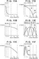
- FIGS. 1A and 1B The details of the above-described AF processing will be described below using flowcharts shown in FIGS. 1A and 1B .
- the following AF processing operations are executed mainly by the camera MPU 125, except when it is clearly stated that other member performs the operation.
- the camera MPU 125 drives or controls the lens unit 100 by transmitting a command or the like to the lens MPU 117, there are cases where it is stated that the camera MPU 125 performs the operation, for the sake of simplification of the description.
- step S1 the camera MPU 125 sets the focus detection regions. It is assumed here that three focus detection regions such as those shown in FIG. 6 are set for the phase-difference AF and the contrast AF.
- step S2 the camera MPU 125 sets a determination flag within the RAM 125b to 1.
- the camera MPU 125 exposes the image sensor 122, reads out image signals, and causes the image processing circuit 124 to generate image signals for the phase-difference AF based on image data within the focus detection regions 218ah, 218bh, and 218ch for the phase-difference AF.
- the camera MPU 125 also causes the image processing circuit 124 to supply RAW image data generated by the image processing circuit 124 to the TVAF unit 130, and causes the TVAF unit 130 to calculate the evaluation values based on the pixel data within the focus detection regions 219a, 219b, and 219c for the TVAF. Note that, before generating the image signals for the phase-difference AF, processing (see Japanese Patent Laid-Open No.
- the focus evaluation value calculated by the TVAF unit 130 is stored in the RAM 125b in the camera MPU 125.
- step S4 the camera MPU 125 determines whether or not a reliable peak (local maximum value) of the focus evaluation value has been detected. If a reliable peak has been detected, the camera MPU 125 advances the processing to step S20 in order to end the focus detection processing.
- the method for calculating the reliability of the peak of the focus evaluation value is not limited, for example, a method described using FIGS. 10A to 13 in Japanese Patent Laid-Open No. 2010-78810 is available.
- a detected peak indicates an apex of a curve, by comparing, with respective threshold values, a difference between the largest value and the smallest value of the focus evaluation value, a length of a portion inclining at an inclination larger than or equal to a fixed value (SlopeThr), and a slope of the inclining portion. If all threshold conditions are satisfied, it can be determined that the peak is reliable.
- both the phase-difference AF and the contrast AF are used. For this reason, if it has been confirmed that a subject on the closer side exists in the same focus detection region or other focus detection regions, the processing may be advanced to step S5 without ending focus detection even if a reliable focus evaluation value peak is detected. However, in this case, the position of the focusing lens 104 corresponding to the reliable focus evaluation value peak is stored, and the stored position of the focusing lens 104 is used as the focus detection result if a reliable focus detection result is not obtained in the processing in step S5 and subsequent steps.
- step S5 the phase-difference AF unit 129 calculates a shift amount (phase difference) between a pair of image signals supplied from the image processing circuit 124, for each of the focus detection regions 218ch, 218ah, and 218bh, and converts the phase difference into a defocus amount using a conversion coefficient that is stored in advance.
- determination is also performed on the reliability of the calculated defocus amount, and only the defocus amount of the focus detection region that is determined to have the predetermined reliability is used in subsequent AF processing.
- the phase difference detected between the pair of image signals contains more errors as the defocus amount is larger, due to the influence of vignetting caused by the lens frame or the like.
- the obtained defocus amount does not have the predetermined reliability (i.e., has a low reliability) in the case where the obtained defocus amount is larger than the threshold value, where the degree of coincidence between the shapes of the pair of image signals is low, or where the contrast of the image signals is low.
- the case where it is determined that the obtained defocus amount has the predetermined reliability will be expressed below as "the defocus amount can be calculated”.
- the case where the defocus amount cannot be calculated for some reason and the case where it is determined that the reliability of the defocus amount is low will be expressed as "the defocus amount cannot be calculated”.
- step S6 the camera MPU 125 checks whether or not the defocus amount can be calculated in all of the focus detection regions 218ah, 218bh, and 218ch for the phase-difference AF that are set in step S1. If the defocus amount can be calculated in all focus detection regions, the camera MPU 125 advances the processing to step S20, and calculates a vertical/horizontal BP correction value (BP1) with respect to a focus detection region in which a defocus amount indicating a subject existing on the closest side is calculated, among the calculated defocus amounts.
- BP1 vertical/horizontal BP correction value
- the reason for selecting the subject on the closest side is because, in general, a subject that a photographer wants to focus on often exists on the closer side.
- the vertical/horizontal BP correction value (BP1) is a value for correcting a difference in the focus detection result in the case of performing focus detection with respect to horizontal contrast of a subject and the focus detection result in the case of performing focus detection with respect to vertical contrast of a subject.
- a general subject has contrast in both the horizontal and vertical directions, and a focus condition of a photographic image is also evaluated while considering the contrast in both the horizontal and vertical directions.
- a focus condition of a photographic image is also evaluated while considering the contrast in both the horizontal and vertical directions.
- an error occurs between a horizontal focus detection result and a focus condition in both the horizontal and vertical directions of a photographic image. This error occurs due to astigmatism or the like in the imaging optical system.
- the vertical/horizontal BP correction value (BP1) is a correction value for correcting this error, and is calculated while considering the selected focus detection region, the position of the focusing lens 104, the position of the first lens group 101 indicating a zoom state, and the like. The details of the calculation method will be described later.
- the camera MPU 125 calculates a color BP correction value (BP2) with respect to the focus detection region that is a target of the correction value calculation in step S20, using vertical or horizontal contrast information.
- the color BP correction value (BP2) is generated by a chromatic aberration in the imaging optical system, and is generated due to a difference between color balance of a signal used in focus detection and color balance of a signal used in a photographic image or a developed image.
- the focus evaluation value is generated based on the output of a pixel (green pixel) having a green (G) color filter, and therefore an in-focus position of a wavelength of green is mainly detected.
- the camera MPU 125 calculates a specific spatial frequency BP correction value (BP3) with respect to the correction target focus detection region using contrast information of a green signal or the luminance signal Y in the vertical or horizontal direction.
- the spatial frequency BP correction value (BP3) is generated mainly due to a spherical aberration in the imaging optical system, and is generated due to a difference between an evaluation frequency (band) of a signal used in focus detection and an evaluation frequency (band) at the time of appreciating a photographic image. Since the image signals at the time of focus detection are read out from the image sensor in the second mode as mentioned above, the output signals have been subjected to the addition and the thinning.
- the spatial frequency BP correction value (BP3) is for correcting a shift in focus detection generated due to the difference in the evaluation band. The details of the method for calculating the spatial frequency BP correction value (BP3) will be described later.
- step S23 the camera MPU 125 corrects a focus detection result DEF_B in accordance with Equation (1) below using the three calculated correction values (BP1, BP2, BP3), and calculates a focus detection result DEF_A after the correction.
- DEF_A DEF_B + BP 1 + BP 2 + BP 3
- the correction values for correcting the focus detection result are calculated in three steps in the order of "vertical/horizontal” (S20), “color” (S21), and “spatial frequency” (S22).
- the influence of the vertical/horizontal BP is separated, and a difference in the in-focus position between the color of the signal used in the photographic image and the color of the signal used at the time of focus detection in contrast information in one direction is calculated as the color BP correction value (BP2).
- a difference in the in-focus position generated due to a difference in the evaluation band of a green color or a specific color of the luminance signal or the like between at the time of appreciating a photographic image and at the time of focus detection is calculated as the spatial frequency BP correction value (BP3).
- step S24 the camera MPU 125 drives the focusing lens 104 through the lens MPU 117, based on the defocus amount DEF_A after the correction calculated using Equation (1).
- step S25 the camera MPU 125 provides a display (AF frame display) indicating the focus detection region in which the defocus amount used in the driving of the focusing lens 104 is calculated, so as to be superimposed on a live view image, for example, on the display 126, and ends the AF processing.
- AF frame display indicating the focus detection region in which the defocus amount used in the driving of the focusing lens 104 is calculated
- step S6 the camera MPU 125 advances the processing to step S7 in FIG. 1B .
- step S7 the camera MPU 125 determines whether or not the determination flag is 1. The determination flag is 1 when the driving of the focusing lens has not been performed even once since the AF operation started. If the driving of the focusing lens has ever been performed, the determination flag is 0. If the determination flag is 1, the camera MPU 125 advances the processing to step S8.
- step S8 the camera MPU 125 cannot calculate the defocus amount in any of the focus detection regions, or if the defocus amount indicating the presence of a subject on the closest side among the calculated defocus amounts is smaller than or equal to a predetermined threshold value A, the camera MPU 125 advances the processing to step S9.
- step S9 the camera MPU 125 drives the focusing lens toward the closer side by a predetermined amount.
- the case where the defocus amount cannot be calculated in any region among the plurality of focus detection regions is the case where a subject on which focusing is to be performed has not been found at this moment.
- the lens is driven by the predetermined amount with respect to all focus detection regions, in order to check the presence of a subject on which focusing is to be performed, such that a later-described change of the focus evaluation value can be determined.
- the case where the defocus amount indicating the presence of a subject on the closest side among the calculated defocus amounts is smaller than or equal to the predetermined threshold value A is the case where the focus detection region that is almost in an in-focus state exists at this moment.
- the lens is driven by the predetermined amount in order to check the possibility that a subject which has not been detected at this moment exists further on the closer side in the focus detection region in which the defocus amount cannot be calculated, such that the later-described change of the focus evaluation value can be determined.
- the predetermined amount by which the focusing lens is driven in step S9 may be determined by considering the sensitivity of the amount of focus movement on the imaging plane with respect to the F value or the lens drive amount of the imaging optical system.
- step S8 if the result in step S8 is No, i.e., if the defocus amount indicating the presence of a subject on the closest side among the calculated defocus amounts is larger than the predetermined threshold value A, the processing proceeds to step S10. In this case, a focus detection region in which the defocus amount can be calculated exists, but this focus detection region is not in an in-focus state. For this reason, in step S10, the camera MPU 125 drives the lens based on the defocus amount indicating the presence of the subject on the closest side among the calculated defocus amounts.
- the camera MPU 125 After driving the lens in step S9 or S10, the camera MPU 125 advances the processing to step S11, sets the determination flag to 0, and returns the processing to step S3 in FIG. 1A .
- step S7 the determination flag is not 1 (i.e., the determination flag is 0)
- the camera MPU 125 advances the processing to step S12.
- step S12 the camera MPU 125 determines whether or not the focus evaluation value in the focus detection region for the TVAF corresponding to the focus detection region in which the defocus amount cannot be calculated has changed by a predetermined threshold value B or larger before and after the driving of the lens.
- the focus evaluation value increases in some cases and decreases in other cases, it is determined in step S12 whether or not the absolute value of the amount of change of the focus evaluation value is larger than or equal to the predetermined threshold value B.
- the case where the absolute value of the amount of change of the focus evaluation value is larger than or equal to the predetermined threshold value B means that, although the defocus amount cannot be calculated, a change of a blurred state of a subject can be detected based on an increase or decrease of the focus evaluation value. For this reason, in the present embodiment, even in the case where the defocus amount cannot be detected by the phase-difference AF, the presence of a subject is determined based on an increase or decrease of the focus evaluation value, and the AF processing is continued. Focus adjustment can thereby be performed on a subject that has a large defocus amount and cannot be detected by the phase-difference AF.
- the predetermined threshold value B used in the determination is changed in accordance with the lens drive amount. If the lens drive amount is large, a larger value is set as the threshold value B than that in the case of a small lens drive amount. This is because, if a subject exists, the amount of change of the focus evaluation value increases in accordance with an increase of the lens drive amount.
- the threshold values B for the respective lens drive amounts are stored in the EEPROM 125c.
- the camera MPU 125 advances the processing to step S13, and determines whether or not the focus detection region whose amount of change of the focus evaluation value is larger than or equal to the threshold value B is only the focus detection region indicating the presence of a subject on an infinite side.
- the case where the focus detection region indicates the presence of a subject on the infinite side is the case where the focus evaluation value decreases when the driving direction of the lens driving is a closer direction, or the case where the focus evaluation value increases when the driving direction of the lens driving is an infinite direction.
- the camera MPU 125 advances the processing to step S14, and drives the lens toward the closer side by a predetermined amount. This is because the focus detection region indicating the presence of a subject on the closer side is included in the focus detection region whose amount of change of the focus evaluation value is larger than or equal to the threshold value B. Note that the reason for giving priority to a subject on the closer side is as mentioned above.
- step S13 the focus detection region whose amount of change of the focus evaluation value is larger than or equal to the threshold value B is only the focus detection region indicating the presence of a subject on the infinite side
- the camera MPU 125 advances the processing to step S15.
- step S15 the camera MPU 125 determines whether or not a focus detection region in which the defocus amount can be calculated exists. In the case where a focus detection region in which the defocus amount can be calculated exists (Yes in S15), the result of the phase-difference AF is given priority to the presence of the subject on the infinite side based on the focus evaluation value, and accordingly the camera MPU 125 advances the processing to step S20 in FIG. 1A .
- step S16 the camera MPU 125 drives the lens toward the infinite side by a predetermined amount based on the change of the focus evaluation value, and returns the processing to step S3 in FIG. 1A .
- the predetermined amount by which the lens is driven in steps S14 and S16 may be determined by considering the defocus amount that can be detected by the phase-difference AF. Although the detectable defocus amount is different depending on the subject, a lens drive amount is set in advance so as to prevent a situation where a subject cannot be detected and is passed through when driving the lens from a state where focus detection cannot be performed.
- the camera MPU 125 advances the processing to step S17, and determines whether or not the focus detection region exists in which the defocus amount can be calculated exists. If the defocus amount cannot be calculated in any of the focus detection regions, the camera MPU 125 advances the processing to step S18, drives the lens to a predetermined fixed point, thereafter further advances the processing to step S19, performs display indicating a no-focus state on the display 126, and ends the AF processing. This is the case where there is no focus detection region in which the defocus amount can be calculated, and there is no focus detection region whose focus evaluation value has changed before and after the lens driving. In this case, since no information indicates the presence of a subject, the camera MPU 125 determines that focusing cannot be performed, and ends the AF processing.
- step S17 if, in step S17, a focus detection region in which the defocus amount can be calculated exists, the camera MPU 125 advances the processing to step S20 in FIG. 1A , corrects the detected defocus amount (S20 to S23), and drives the focusing lens 104 to the in-focus position in step S24. Thereafter, in step S25, the camera MPU 125 performs display indicating an in-focus state on the display 126, and ends the AF processing.
- FIG. 7 is a flowchart showing the details of the vertical/horizontal BP correction value (BP1) calculation processing.
- the camera MPU 125 obtains vertical/horizontal BP correction information.
- the vertical/horizontal BP correction information is information of a difference between an in-focus position in the horizontal direction (first direction) and an in-focus position in the vertical direction (second direction).
- the vertical/horizontal BP correction information is stored in advance in the lens memory 118 in the lens unit 100, and the camera MPU 125 obtains the vertical/horizontal BP correction information by requesting it from the lens MPU 117.
- the vertical/horizontal BP correction information may be stored in association with identification information of the lens unit in a nonvolatile area of the camera RAM 125b.
- FIG. 8A shows exemplary vertical/horizontal BP correction information.
- the vertical/horizontal BP correction information corresponding to the center focus detection regions 219a and 218ah in FIG. 6 is shown here, the vertical/horizontal BP correction information corresponding to the other focus detection regions 219c, 218ch, 219b, and 218bh is also stored.
- the focus detection correction values of focus detection regions existing at symmetrical positions with respect to the optical axis of the imaging optical system are equal to each other in design. Since the focus detection regions 219c and 218ch and the focus detection regions 219b and 218bh respectively satisfy this asymmetrical relationship in the present embodiment, the vertical/horizontal BP correction information of one of the focus detection region in each pair may be stored. Also, if the correction value does not significantly change depending on the position of the focus detection region, the correction value may be stored as a common value.
- each of a zoom position (angle of view) and a focusing lens position (in-focus distance) in the imaging optical system is divided into 8 zones, and the focus detection correction values BP111 to BP188 are stored for respective zones.
- the number of divided zones is larger, a more accurate correction value suitable for the position of the first lens group 101 and the position of the focusing lens 104 in the imaging optical system can be obtained.
- the vertical/horizontal BP correction information can be used in both the contrast AF and the phase-difference AF.
- step S100 the camera MPU 125 obtains the correction value corresponding to the zoom position and the focusing lens position suitable for a correction target focus detection result.
- step S101 the camera MPU 125 determines whether reliable focus detection results have been obtained with respect to both the horizontal and vertical directions in the correction target focus detection region.
- the method for determining the reliability of the focus detection result is as described above regarding both the phase-difference AF and the contrast AF. Since only horizontal focus detection is performed in the phase-difference AF in the present embodiment, reliable focus detection results with respect to both the horizontal and vertical directions are obtained by the contrast AF. For this reason, the following description regarding the vertical/horizontal BP correction value assumes the contrast AF, whereas similar processing may be performed also in the case of performing focus detection by the phase-difference AF in both the horizontal and vertical directions. If it is determined in step S101 that both the horizontal and vertical focus detection results are reliable, the camera MPU 125 advances the processing to step S102.
- step S102 the camera MPU 125 determines whether or not a difference between the horizontal focus detection result and the vertical focus detection result is appropriate. This is processing performed in order to handle a problem of a shifting of focus between far and close subjects, which occurs when subjects at a far distance and at a close distance are included in the focus detection region. For example, if the far subject has horizontal contrast and the close subject has vertical contrast, there are cases where the absolute value is larger than an error that is caused by astigmatism in the imaging optical system, or where the focus detection results have opposite signs. If the difference between the horizontal focus detection result and the vertical focus detection result is larger than a predetermined determination value C, the camera MPU 125 determines that the difference is not appropriate (i.e., a shifting of focus has occurred).
- the camera MPU 125 selects the horizontal direction or the vertical direction as a direction indicating the focus detection result that is further on the closer side, and advances the processing to step S104.
- the determination value C may be uniquely determined to be a value that significantly exceeds a possible difference caused by an aberration or the like, or may be set using the correction information obtained in step S100.
- step S102 If it is determined in step S102 that the difference between the horizontal focus detection result and the vertical focus detection result is appropriate, the camera MPU 125 advances the processing to step S106.
- step S101 only the focus detection result in either the horizontal direction or the vertical direction is reliable, or if, in step S102, only one of the horizontal direction and the vertical direction is selected
- the camera MPU 125 advances the processing to step S104.
- step S104 the camera MPU 125 selects the direction of the focus detection result.
- the camera MPU 125 selects the direction in which the reliable focus detection result is calculated, or the direction in which the focus detection result corresponding to a subject that is further on the closer side is calculated in the determination regarding a shifting of focus.
- step S105 the camera MPU 125 determines whether or not weighting in the horizontal direction and the vertical direction can be performed.
- step S105 is executed, from the viewpoint of the reliability of the focus evaluation value and a shifting of focus, determination for calculating the vertical/horizontal BP correction value is performed again even though reliable focus detection results have not been obtained in both the horizontal and vertical directions. The reason thereof will now be described in detail using FIG. 8B .
- FIG. 8B is a diagram showing an exemplary relationship between the position of the focusing lens 104 in the selected focus detection region and the focus evaluation values.
- Curves E_h and E_v in FIG. 8B denote changes of the horizontal focus evaluation value and the vertical focus evaluation value that are detected by the contrast AF.
- Signs LP1, LP2, and LP3 denote focusing lens positions.
- FIG. 8B shows the case where LP3 is obtained as a reliable focus detection result from the horizontal focus evaluation value E_h, and LP1 is obtained as a reliable focus detection result from the vertical focus evaluation value E_v. It is determined that a shifting of focus has occurred since LP1 and LP3 are significantly different, and the horizontal focus detection result LP3, which is the focus detection result that is further on the closer side, is selected in step S104.
- step S105 the camera MPU 125 determines whether or not a vertical focus detection exists near the selected horizontal focus detection result LP3. Since LP2 exists in the situation in FIG. 8B , the camera MPU 125 determines that weighting in the horizontal and vertical directions can be performed, advances the processing to step S106, and calculates the correction value for the focus detection result LP3 while considering the influence of the focus detection result LP2.
- BP1_B which is one element in FIG. 8A
- the horizontal focus evaluation value at LP3 in FIG. 8B is E_hp
- the vertical focus evaluation value at LP2 is E_vp.
- the camera MPU 125 calculates the vertical/horizontal BP correction value BP1 in accordance with Equation (2) below, based on the ratio of the focus evaluation value in a direction perpendicular to the direction subjected to the correction to the total of the focus evaluation values.
- Equation (2) Equation (2) below
- the correction value BP1 is calculated using Equation (2) in the case where the focus detection result on the closer side is the horizontal detection result, or using Equation (3) in the case of the vertical detection result.
- the vertical/horizontal BP correction value (BP1) is calculated while determining that a subject contains a large amount of contrast information, based on the information indicating that the focus evaluation value is large.
- the vertical/horizontal BP correction information is: (focus detection position of subject having contrast information only in vertical direction)-(focus detection position of subject having contrast information only in horizontal direction). For this reason, the correction value BP1 for correcting the horizontal focus detection result and the correction value BP1 for correcting the vertical focus detection result have opposite signs.
- the camera MPU 125 ends the vertical/horizontal BP correction value calculation processing.
- step S105 if it is determined in step S105 that a vertical focus detection result does not exist near the selected horizontal focus detection result LP3, the camera MPU 125 advances the processing to step S103.
- the correction value is calculated in accordance with the contrast information of a subject in different directions, and therefore the correction value can be accurately calculated in accordance with the pattern of the subject. Note that, although the case where a shifting of focus has occurred between subjects has been described in FIG. 8B , the correction value is also calculated based on a similar idea when one local maximum value is detected in each of the horizontal and vertical directions, and one of the focus detection results is not reliable.
- the correction value calculation method in step S106 is not limited thereto.
- the correction value may be calculated while assuming that the amount of the contrast information of the subject in the horizontal direction is the same as that in the vertical direction.
- the amount of change of a correlation amount calculated in correlation calculation in the phase-difference AF may be used as a coefficient of the weighting in the correction value calculation.
- the fact that the amount of change of the correlation amount is larger as the amount of the contrast information of the subject is larger is used, as in the case where a difference between brightness and darkness of the subject is large, or in the case where the number of edges with a difference in brightness and darkness is large.
- the evaluation value is not limited to the amount of change of the correlation amount and may be any kind of evaluation value, as long as a similar relationship is obtained therewith.
- the vertical/horizontal BP correction value is not calculated using these focus detection results, and the influence of a shifting of focus can thereby be reduced. Furthermore, in the case where a shifting of focus is assumed as well, more accurate correction can be performed by weighting the correction values based on which of the focus evaluation values in the respective directions are large or small.
- FIG. 9A is a flowchart showing the details of the color BP correction value (BP2) calculation processing.
- the camera MPU 125 obtains color BP correction information.
- the color BP correction information is information of a difference between an in-focus position detected using a green (G) signal and an in-focus position detected using signals of other colors (red (R), blue (B)).
- the color BP correction information is stored in advance in the lens memory 118 in the lens unit 100, and the camera MPU 125 obtains the color BP correction information by requesting it from the lens MPU 117.
- the color BP correction information may be stored in the nonvolatile area of the camera RAM 125b.
- the color BP correction information can be used in both the contrast AF and the phase-difference AF.
- step S200 the camera MPU 125 obtains the correction value corresponding to the zoom position and the focusing lens position suitable for a correction target focus detection result.
- step S201 the camera MPU 125 calculates the color BP correction value. If, in step S200, BP_R has been obtained as one element in FIG. 9B , and BP_B has been obtained as one element in FIG. 9C , the camera MPU 125 calculates the color BP correction value BP2 in accordance with Equation (4) below.
- BP 2 K_R ⁇ BP_R + K_B ⁇ BP_B
- K_R and K_B are coefficients for correction information of respective colors. These coefficients are values correlating with a relationship regarding which the volumes of the red (R) and blue (B) information with respect to the volume of the green (G) information contained in the subject is larger, K_R takes a larger value with respect to a subject containing a large amount of red color, and K_B takes a larger value with respect to a subject containing a larger amount of blue color. Both K_R and K_B take small values with respect to a subject containing a larger amount of green color. K_R and K_B may be set in advance based on representative spectral information of the subject.
- K_R and K_B may be set in accordance with the spectral information of the subject.
- the method for storing the correction values is not limited thereto.
- a configuration may be employed in which a coordinate system is set with the intersecting point of the image sensor and the optical axis of the imaging optical system as an origin, and the horizontal and vertical directions of the image capture apparatus respectively as an X axis and a Y axis, and the correction value at the center coordinates of the focus detection region is obtained using a function of X and Y.
- the volume of information to be stored as the focus detection correction values can be reduced.
- the correction value used in focus detection in which calculation is performed using the vertical/horizontal BP correction information or the color BP correction information is calculated assuming that the correction value does not depend on spatial frequency information that the pattern of a subject has. For this reason, accurate correction can be performed without increasing the amount of correction information to be stored.
- the method for calculating the correction value is not limited thereto.
- a correction value may be calculated in accordance with spatial frequency components of a subject, using the vertical/horizontal BP correction information or the color BP correction information with respect to each spatial frequency.
- FIG. 10A is a flowchart showing the details of the spatial frequency BP correction value (BP3) calculation processing.
- the camera MPU 125 obtains spatial frequency BP correction information.
- the spatial frequency BP correction information is information regarding an image forming position in the imaging optical system with respect to each spatial frequency of a subject.
- the spatial frequency BP correction information is stored in advance in the lens memory 118 in the lens unit 100, and the camera MPU 125 obtains the spatial frequency BP correction information by requesting it from the lens MPU 117.
- the spatial frequency BP correction information may be stored in the nonvolatile area of the camera RAM 125b.
- FIG. 10B showing a defocus MTF (Modulation Transfer Function) of the imaging optical system.
- the horizontal and vertical axes in FIG. 10B show the position of the focusing lens 104 and the intensity of the MTF, respectively.
- Four curves shown in FIG. 10B are MTF curves with respect to respective spatial frequencies, and indicate the case where the spatial frequency changes from low to high frequencies in the order of MTF1, MTF2, MTF3, and MTF4.
- the MTF curve of a spatial frequency F1 (lp/mm) corresponds to MTF1
- spatial frequencies F2, F3, and F4 (lp/mm) correspond to MTF2, MTF3, and MTF4, respectively.
- LP4, LP5, LP6, and LP7 indicate the positions of the focusing lens 104 corresponding to the local maximum values of the respective defocus MTF curves.
- the stored spatial frequency BP correction information is obtained by discretely sampling the curves in FIG. 10B .
- MTF data for 10 focusing lens positions are sampled with respect to one MTF curve, and for example, 10 sets of data is stored as MTF1(n) (1 ⁇ n ⁇ 10) with respect to MTF1.
- the zoom position (angle of view) of the imaging optical system and the focusing lens position (in-focus distance) are divided into 8 zones at each position in the focus detection region, and the spatial frequency BP correction information of each zone is stored, similarly to the vertical/horizontal BP correction information and the color BP correction information. As the number of divided zones is larger, a more accurate correction value suitable for the position of the first lens group 101 and the position of the focusing lens 104 in the imaging optical system can be obtained. Also, the spatial frequency BP correction information can be used in both the contrast AF and the phase-difference AF.
- step S300 the camera MPU 125 obtains the correction value corresponding to the zoom position and the focusing lens position suitable for a correction target focus detection result.
- the camera MPU 125 calculates a band of a signal used when performing the contrast AF and the phase-difference AF in the correction target focus detection region.
- the camera MPU 125 calculates an AF evaluation band while considering the influence of a subject, the imaging optical system, the sampling frequency of the image sensor, and a digital filter used in the evaluation. A method for calculating the AF evaluation band will be described later.
- the camera MPU 125 calculates a band of a signal used in a photographic image. As in the calculation of the AF evaluation band in step S302, the camera MPU 125 calculates a photographic image evaluation band, while considering the influence of the subject, the imaging optical system, frequency characteristics of the image sensor, and an evaluation band of a person who appreciates the photographic image.
- FIGS. 11A to 11F indicates intensities with respect to the respective spatial frequencies, with the horizontal and vertical axes respectively indicating the spatial frequency and the intensity.
- FIG. 11A shows a spatial frequency characteristic (I) of the subject.
- F1, F2, F3, and F4 on the horizontal axis are spatial frequencies corresponding to the MTF curves (MTF1 to MTF4) in FIG. 10B .
- Nq indicates a Nyquist frequency, which is determined by the pixel pitch of the image sensor 122.
- F1 to F4 and Nq are also similarly shown in FIGS. 11B to 11F , which will be described below.
- a representative value stored in advance is used as the spatial frequency characteristic (I) of the subject.
- the spatial frequency characteristic (I) of the subject which is indicated by a continuous curve in FIG. 11A , has discrete values I(n) (1 ⁇ n ⁇ 4) corresponding to the spatial frequencies F1, F2, F3, and F4.
- the spatial frequency characteristic of the subject to be used may be changed in accordance with the subject for which focus detection is performed.
- the spatial frequency information (power spectrum) of the subject can be obtained by applying FFT processing or the like on an image signal obtained by imaging.
- a correction value suitable for a subject for which focus detection is actually performed can be calculated, and accordingly accurate focus detection can be performed.
- some kinds of spatial frequency characteristics stored in advance may be appropriately used depending on whether the contrast information of the subject is large or small.
- FIG. 11B shows a spatial frequency characteristic (O) of the imaging optical system.
- This information may be obtained through the lens MPU 117, or may be stored in the RAM 125b in the camera.
- the stored information may be the spatial frequency characteristics in respective defocus states, or may be only a spatial frequency characteristic in an in-focus state. Since the spatial frequency BP correction value is calculated near an in-focus position, accurate correction can be performed using the spatial frequency in an in-focus state. However, more accurate focus adjustment can be performed using the spatial frequency characteristics in respective defocus states, although a calculation load increases.
- the spatial frequency characteristic in a defocus state to be used may be selected using the defocus amount obtained by the phase-difference AF.
- the spatial frequency characteristic (O) of the imaging optical system which is indicated by a continuous curve in FIG. 11B , has discrete values O(n) (1 ⁇ n ⁇ 4) corresponding to the spatial frequencies F1, F2, F3, and F4.
- FIG. 11C shows a spatial frequency characteristic (L) of the optical low pass filter 121. This information is stored in the RAM 125b within the camera.
- the spatial frequency characteristic (L) of the optical low pass filter 121 which is indicated by a continuous curve in FIG. 11C , has discrete values L(n) (1 ⁇ n ⁇ 4) corresponding to the spatial frequencies F1, F2, F3, and F4.
- FIG. 11D shows spatial frequency characteristics (M1, M2) at the time of signal generation.
- the image sensor in the present embodiment has two readout modes.
- the first readout mode i.e., in the all-pixel readout mode
- the spatial frequency characteristic does not change when generating a signal, as indicated by M1.
- the second readout mode i.e., in the thinning readout mode
- the spatial frequency characteristic changes when generating a signal, as indicated by M2.
- signals are added at the time of the thinning in the X direction to improve the S/N ratio, and therefore a low-pass effect is generated by the addition.
- M2 in FIG. 11D indicates the spatial frequency characteristic at the time of generating a signal in the second readout mode.
- the low pass effect achieved by the addition is shown without taking the influence of the thinning into consideration.
- the spatial frequency characteristics (M1, M2) at the time of signal generation which are indicated by continuous curves in FIG. 11D , have discrete values M1(n) and M2(n) (1 ⁇ n ⁇ 4) corresponding to the spatial frequencies F1, F2, F3, and F4.
- FIG. 11E shows a spatial frequency characteristic (D1) indicating the sensitivity with respect to each spatial frequency at the time of appreciating a photographic image, and a spatial frequency characteristic (D2) of a digital filter used in processing of an AF evaluation signal.
- D1 a spatial frequency characteristic
- D2 a spatial frequency characteristic of a digital filter used in processing of an AF evaluation signal.
- the sensitivity with respect to each spatial frequency at the time of appreciating a photographic image is affected by individual differences of a person who appreciate the image, the image size, the distance at the time of appreciating the image, the environment in which the image is appreciated, such as the brightness, and the like.
- the sensitivity with respect to each spatial frequency at the time of appreciation is set and stored as a representative value.
- the camera MPU 125 calculates a photographic image evaluation band W1 and an AF evaluation band W2, based on Equations (5) and (6) below.
- W 1 n I n ⁇ O n ⁇ L n ⁇ M 1 n ⁇ D 1 n 1 ⁇ n ⁇ 4
- W 2 n I n ⁇ O n ⁇ L n ⁇ M 2 n ⁇ D 2 n 1 ⁇ n ⁇ 4
- FIG. 11F shows the photographic image evaluation band W1 (first evaluation band) and the AF evaluation band W2 (second evaluation band).
- the information stored in the camera may be W1 and W2 that are calculated in advance. As described above, when the digital filter or the like used in the AF evaluation is changed, the correction value can be calculated while flexibly responding to this change, by performing the calculation every time the correction is performed. On the other hand, if W1 and W2 are store in advance, the calculation of Equations (5) and (6) and the storage capacity for various data can be reduced.
- a configuration may also be employed in which, for example, only the spatial frequency characteristics of the imaging optical system and the subject are calculated in advance and stored in the camera, thereby reducing the data storage capacity and the amount of calculation.
- FIGS. 11A to 11F have been described using the discrete values corresponding to four spatial frequencies (F1 to F4), for the purpose of simplification of the description.
- F1 to F4 the discrete values corresponding to four spatial frequencies
- a larger number of spatial frequencies with respect to which data is held will lead to more correct reproduction of the spatial frequency characteristics of the photographic image and the AF evaluation band, and the correction value can be accurately calculated.
- the amount of calculation can be reduced by reducing the number of spatial frequencies to be weighted.
- the subsequent calculation may be performed while holding one spatial frequency representing the photographic image evaluation band and one spatial frequency representing the AF evaluation band spatial frequency.
- the camera MPU 125 calculates the spatial frequency BP correction value (BP3).
- the camera MPU 125 initially calculates a defocus MTF (C1) of the photographic image and a defocus MTF (C2) of a focus detection signal.
- C1 and C2 are calculated using the defocus MTF information obtained in step S300 and the evaluation bands W1 and W2 obtained in steps S301 and S302, in accordance with Equation (7) below.
- C 1 n MTF 1 n ⁇ W 1 1 + MTF 2 n ⁇ W 1 2 + MTF 3 n ⁇ W 1 3 + MTF 4 n ⁇ W 1 4
- C 2 n MTF 1 n ⁇ W 2 1 + MTF 2 n ⁇ W 2 2 + MTF 3 n ⁇ W 2 3 + MTF 4 n ⁇ W 2 4
- the defocus MTF information with respect to the respective spatial frequencies shown in FIG. 10B is added based on the weighting of the evaluation bands of the photographic image and the AF calculated in steps S301 and S302, and the defocus MTF (C1) of the photographic image and the defocus MTF (C2) of the AF are obtained.
- FIG. 10C shows C1 and C2, which are the two obtained defocus MTFs.
- the horizontal and vertical axes respectively indicate the position of the focusing lens 104 and the MTF value obtained by performing weighted addition with respect to each spatial frequency.
- the camera MPU 125 detects a local maximum value position of each MTF curve.
- P_img first image forming position
- P_AF second image forming position
- step S303 the camera MPU 125 calculates the spatial frequency BP correction value (BP3) using Equation (9) below.
- BP 3 P_AF ⁇ P_img
- Equation (9) the correction value for correcting an error that may possibly occur between the in-focus position of the photographic image and the in-focus position detected by the AF can be calculated.
- the in-focus position of the photographic image changes depending on the spatial frequency characteristics of the subject, the imaging optical system, and the optical low pass filter, the spatial frequency characteristics at the time of signal generation, the spatial frequency characteristics indicating the sensitivity with respect to each frequency at the time of appreciation, image processing performed on the photographic image, and the like.
- an in-focus position of the photographic image can be accurately calculated by going back to a process of generating the photographic image and calculating the spatial frequency characteristics.
- the in-focus position of the photographic image is changed in accordance with the recording size of the photographic image, super-resolution processing performed in image processing, sharpness, or the like.
- the image size or the magnification ratio with which the photographic image after being recorded is appreciated, the appreciating distance at which the photographic image is appreciated, and the like affect the evaluation band of the appreciating person.
- the in-focus position of the photographic image is changed by setting characteristics in which high-frequency components of the evaluation band of the appreciating person are more weighted as the image size is larger, and as the appreciating distance is shorter.
- the in-focus position detected by the AF similarly changes depending on the spatial frequency characteristics of the subject, the imaging optical system, and the optical low pass filter, the spatial frequency characteristics at the time of signal generation, the digital filter spatial frequency used in the AF evaluation, and the like.
- the spatial frequency characteristics are calculated by going back to the process of generating a signal used in the AF, and the in-focus position detected by the AF can thereby be accurately calculated.
- the AF in the first readout mode can also be flexibly handled. In this case, a weighting coefficient need only be calculated by changing the spatial frequency characteristics at the time of signal generation to characteristics corresponding to the first readout mode.
- the lens unit 100 can be replaced. If the lens unit 100 is replaced, the lens MPU 117 transmits the defocus MTF information corresponding to the respective spatial frequencies to the camera body 120. The camera MPU 125 then calculates the in-focus position of the photographic image and the in-focus position detected by the AF, and accordingly the correction value can be accurately calculated for each interchangeable lens.
- the lens unit 100 may transmit not only the defocus MTF information but also information such as the spatial frequency characteristic of the imaging optical system to the camera body 120. The way of making use of this information is as described above.
- the pixel pitch, characteristics of the optical low pass filter, or the like changes in some cases.
- the correction value suitable for the characteristics of the camera body 120 is calculated, and accordingly accurate correction can be performed.
- the correction value is calculated by the camera MPU 125 in the above description, the calculation may be performed by the lens MPU 117.
- a configuration may be employed in which the camera MPU 125 transmits, to the lens MPU 117, various kinds of information that has been described using FIGS. 11A to 11F , and the lens MPU 117 calculates the correction value using the defocus MTF information and the like.
- the lens MPU 117 need only correct the in-focus position transmitted from the camera MPU 125 and drive the lens.
- the correction value for the AF is calculated while paying attention to the characteristics (vertical/horizontal, color, spatial frequency band) of the signal used in focus detection. For this reason, the correction value can be calculated using a similar method, regardless of the AF method. Since the correction method and data to be used in the correction do not need to be held for each AF method, the data storage capacity and the calculation load can be reduced.
- the defocus MTF information is used as the value representing the characteristics of the imaging optical system with respect to the respective spatial frequencies.
- the data volume of the defocus MTF information is large, which increases the storage capacity and the calculation load.
- the spatial frequency BP correction value is calculated using local maximum value information of the defocus MTF. It is thereby possible to achieve saving of the capacity of the lens memory 118 or the RAM 125b, a reduction in the amount of communication between the lens and camera, and a reduction in the load of the calculation performed by the camera MPU 125, for example.
- FIG. 2 the block diagram ( FIG. 2 ) of the image capture apparatus, the diagrams ( FIGS. 3A to 5 ) illustrating the focus detection methods, the diagram ( FIG. 6 ) illustrating the focus detection regions, and the flowcharts ( FIGS. 1A , 1B , 7 , and 9A ) of the focus detection processing and various kinds of BP correction value calculation processing will be also used in the present embodiment.
- the flowchart ( FIG. 10A ) of the spatial frequency BP correction value calculation processing and the diagrams ( FIGS. 11A to 11F ) illustrating the evaluation bands will also be used.
- a method for calculating the spatial frequency BP correction value (BP3) in the present embodiment will now be described using FIG. 12 .
- step S300 the camera MPU 125 obtains spatial frequency BP correction information.
- FIG. 12 shows positions of the focusing lens 104 at which the defocus MTFs take their local maximum values with respect to respective spatial frequencies, which are characteristics of the imaging optical system.
- the focusing lens positions LP4, LP5, LP6, and LP7 at which the defocus MTFs reach their peaks (local maximum values) with respect to the discrete spatial frequencies F1 to F4 shown in FIG. 10B are shown along the vertical axis.
- LP4 to LP7 are stored as MTF_P(n) (1 ⁇ n ⁇ 4) in the lens memory 118 or the RAM 125b. The stored information is associated with the position of the focus detection region, the zoom position, and the focusing lens position, as in the first embodiment.
- step S300 in the spatial frequency BP correction value processing shown in FIG. 10A the camera MPU 125 obtains a correction value corresponding to the zoom position and the focusing lens position suitable for a correction target focus detection result.
- the camera MPU 125 performs processing similar to that in the first embodiment.
- step S303 the camera MPU 125 calculates the spatial frequency BP correction value (BP3).
- the camera MPU 125 initially calculates an in-focus position (P_img) of the photographic image and an in-focus position (P_AF) detected by the AF, in accordance with Equations (10) and (11) below.
- the calculation uses the defocus MTF information MTF_P(n) obtained in step S300 and the evaluation bands W1 and W2 obtained in steps S301 and S302.
- P_img MTF_P 1 ⁇ W 1 1 + MTF_P 2 ⁇ W 1 2 + MTF_P 3 ⁇ W 1 3 + MTF_P 4 ⁇ W 1 4
- P_AF MTF_P 1 ⁇ W 2 1 + MTF_P 2 ⁇ W 2 2 + MTF_P 3 ⁇ W 2 3 + MTF_P 4 ⁇ W 2 4
- the local maximum value information MTF_P(n) of the defocus MTF with respect to each spatial frequency shown in FIG. 12 is subjected to weighted addition using the evaluation bands W1 and W2 of the photographic image and the AF calculated in steps S301 and S302.
- the in-focus position (P_img) of the photographic image and the in-focus position (P_AF) detected by the AF are thereby calculated.
- the camera MPU 125 calculates the spatial frequency BP correction value (BP3) as in the first embodiment, using Equation (9) below.
- BP 3 P_AF ⁇ P_img
- the spatial frequency BP correction value can be calculated more easily.
- the accuracy of the spatial frequency BP correction value in the present embodiment is slightly lower than that in the first embodiment, it is possible to achieve a reduction in the amount of information stored for calculating the spatial frequency BP correction value, a reduction in the amount of communication between the lens and the camera, and a reduction in the load of the calculation performed by the camera MPU 125.
- the method for calculating the spatial frequency BP correction value is different from those in the above embodiments.
- the spatial frequency BP correction value is not calculated when the calculation is not necessary, thereby reducing the amount of communication between the lens and camera and reducing the load of the calculation performed by the camera MPU 125, while not lowering the accuracy of the spatial frequency BP correction value.
- FIG. 2 the block diagram ( FIG. 2 ) of the image capture apparatus, the diagrams ( FIGS. 3A to 5 ) illustrating the focus detection methods, the diagram ( FIG. 6 ) illustrating the focus detection regions, and the flowcharts ( FIGS. 1A , 1B , 7 , and 9A ) of the focus detection processing and various kinds of BP correction value calculation processing will be also used in the present embodiment.
- the diagrams ( FIGS. 10B to 10C ) relating to the spatial frequency BP correction value calculation processing will also be used.
- FIG. 13 A method for calculating the spatial frequency BP correction value (BP3) in the present embodiment will now be described using a flowchart in FIG. 13 .
- Processing in FIG. 13 that is similar to processing in FIG. 10A will be given the same reference numeral, and a redundant description will be omitted.
- step S3000 the camera MPU 125 determines whether or not the spatial frequency BP correction value needs to be calculated.
- the calculation of the correction value is omitted if a condition is satisfied under which the difference between the two evaluation bands is sufficiently small. For example, if the signal used in the AF is also a signal read out in the first mode, the photographic image evaluation band is equal to the AF evaluation band. Furthermore, when using, in processing of AF evaluation signal, a digital filter having a spatial frequency characteristic similar to the spatial frequency characteristic indicating the sensitivity with respect to each spatial frequency at the time of appreciating the photographic image, the spatial frequency characteristic at the time of appreciation is equal to the spatial frequency characteristic of the digital filter. This situation occurs in the case of displaying an image to be displayed on the display 126 in an enlarging manner, for example.
- the photographic image evaluation band is equal to the AF evaluation band when the photographic image is generated using the signal which is read out in the second readout mode. This situation occurs in the case where the size of a recorded image of the photographic image is set to be small.
- step S3000 If, in step S3000, any of such predetermined conditions is satisfied, the camera MPU 125 determines that the calculation of the correction value is not necessary, and advances the processing to step S3001.
- step S3001 since the correction value is not calculated, the camera MPU 125 substitutes 0 for BP3, and ends the spatial frequency BP correction value (BP3) calculation processing.
- step S3000 determines that the calculation of the correction value is necessary. If it is determined in step S3000 that the calculation of the correction value is necessary, the camera MPU 125 performs steps S300 to S303 as in the first embodiment (or the second embodiment).
- the present embodiment thus omits the calculation of the correction value if it is determined that the calculation of the spatial frequency BP correction value is not necessary, the amount of data communication and the calculation load at the time of calculating the correction value can be reduced, although the volume of data stored for calculating the correction value cannot be reduced.
- the present embodiment can be combined with the second embodiment, and in this case, the amount of data communication and the calculation load at the time of calculating the correction value can be further reduced, not to mention a reduction in the volume of data stored for calculating the correction value.
- the vertical/horizontal BP correction value and the color BP correction value can also be omitted, if it is determined that these correction values are not necessary. For example, when performing focus detection while considering both the vertical and horizontal contrast, the calculation of the vertical/horizontal BP correction value may be omitted. If a color signal used in the photographic image is equal to a color signal used in focus detection, the calculation of the color BP correction value may be omitted.
- the present embodiment is different from the first embodiment mainly in the methods for calculating various BP correction values.
- the vertical/horizontal BP correction value, the color BP correction value, and the spatial frequency BP correction value are calculated as different correction values.
- the vertical/horizontal BP correction value and the color BP correction value also depend on the spatial frequency
- the vertical/horizontal BP correction value and the color BP correction value are also calculated while considering the spatial frequency in the fourth embodiment.
- the correction values can thereby be calculated more accurately, although the capacity necessary for the lens memory 118 or the RAM 125b increases.
- a reduction in the amount of calculation can be achieved by changing the order of calculation of the BP correction values, information of temporarily stored coefficients, and the like.
- FIG. 2 the block diagram ( FIG. 2 ) of the image capture apparatus, the diagrams ( FIGS. 3A to 5 ) illustrating the focus detection methods, the diagram ( FIG. 6 ) illustrating the focus detection region, and the diagrams ( FIGS. 11A to 11F ) illustrating the evaluation bands are common in the present embodiment, and accordingly will also be used in the following description.
- FIGS. 14 to 17 A method for calculating a BP correction value (BP) in the present embodiment will now be described using FIGS. 14 to 17 .
- FIG. 14 processing similar to the focus detection processing in the first embodiment are given the same reference numerals as those in FIG. 1A .
- FIG. 14 is different from FIG. 1A in that steps S20 to S22 are replaced with step S400, and step S23 is replaced with step S401.
- the camera MPU 125 calculates a BP correction value (BP) for collectively correcting various error factors, such as the direction (vertical/horizontal), the color, and the spatial frequency.
- BP BP correction value
- step S401 the camera MPU 125 corrects the focus detection result DEF_B using the calculated BP correction values (BP) in accordance with Equation (12), and calculates a focus detection result DEF_A after the correction.
- DEF_A DEF_B + BP
- the BP correction value is calculated using information of the positions of the focusing lens 104 indicating local maximum values of the defocus MTF of six spatial frequencies, which are combinations of three colors, namely red (R), green (G), and blue (B), and two directions, namely vertical and horizontal directions. It is thereby possible to consider the dependency of the color and the direction (vertical and horizontal) on the spatial frequencies, calculate a more accurate BP correction value, and improve the correction accuracy.
- FIG. 15 is a flowchart showing the details of the BP correction value calculation processing in step S400 in FIG. 14 .
- step S500 the camera MPU 125 obtains parameters (calculation conditions) necessary for calculating the BP correction value.
- the BP correction value changes with a change of the imaging optical system and a change of the focus detection optical system, such as a change of the position of the focusing lens 104, the position of the first lens group 101 indicating a zoom state, and the position of the focus detection region.
- the camera MPU 125 obtains information of the position of the focusing lens 104, the position of the first lens group 101 indicating the zoom state, and the position of the focus detection region, for example.
- the camera MPU 125 obtains setting information regarding colors and evaluation directions of the signal used in focus detection and the signal used in the photographic image.
- FIG. 16A shows exemplary setting information regarding the colors and the evaluation directions.
- This setting information is information indicating the degree of weighting with respect to combinations of the colors (red, green, and blue) and the directions (horizontal and vertical) of contrast with which a focus condition is evaluated.
- the setting information for focus detection is different from the setting information for the photographic image. For example, when correcting a result of the contrast AF using a horizontal green signal, the setting information for focus detection may be defined as follows:
- the setting information for the photographic image may be defined as follows:
- step S501 the camera MPU 125 determines whether or not a later-described peak coefficient has been changed. This determination is performed in order to omit recalculation of the peak coefficient, in the case where various conditions are identical in previously-performed BP correction value calculation and the current BP correction value calculation.
- the camera MPU 125 determines that the peak coefficient has not been changed if there has been no change in the setting information ( FIG. 16A ) regarding the color and the evaluation direction for focus detection and the photographic image and in the position of the focus detection region, and advances the processing to step S505, skipping steps S502 to S504.
- the camera MPU 125 advances the processing to step S502 and obtains the BP correction information.
- the BP correction information is information regarding the image forming position in the imaging optical system with respect to each spatial frequency of a subject.
- Equation (13) Each of the aforementioned six combinations of the three colors and the two directions is expressed by Equation (13) below, with the spatial frequency f and the position (x, y) of the focus detection region on the image sensor as variables.
- Equation (13) is an equation of information MTF_P_RH of the position of the focusing lens 104 at which the defocus MTF with respect to each spatial frequency of a red (R) signal corresponding to the horizontal (H) direction takes its local maximum value
- rh(n) (0 ⁇ n ⁇ 8) is stored in advance in the lens memory 118 in the lens unit 100, and the camera MPU 125 obtains rh(n) (0 ⁇ n ⁇ 8) by requesting it from the lens MPU 117.
- rh(n) (0 ⁇ n ⁇ 8) may be stored in the nonvolatile area of the camera RAM 125b.
- Coefficients (rv, gh, gv, bh, and bv) in each of the combinations of “red and vertical” (MTF_P_RV), “green and horizontal” (MTF_P_GH), “green and vertical” (MTF_P_GV), “blue and horizontal” (MTF_P_BH), and “blue and vertical” (MTF_P_BV) may also be similarly stored and obtained.
- step S503 the camera MPU 125 performs, with respect to the obtained BP correction information, weighting relating to the position of the focus detection region, the color of an evaluation signal, and the contrast direction. Initially, the camera MPU 125 calculates the BP correction information using the information regarding the position of the focus detection region at the time of calculating the BP correction value.
- Equation (13) is expressed in the form of Equation (14) below.
- MTF_P_RHF Arh ⁇ f 2 + Brh ⁇ f + Crh
- the camera MPU 125 also similarly calculates MTF_P_RVF, MTF_P_GHF, MTF_P_GVF, MTF_P_BHF, and MTF_P_BVF. These correspond to defocus MTF intermediate information.
- FIG. 16B shows exemplary BP correction information after substituting the focus detection region position information in step S503, with the horizontal and vertical axes respectively indicating the spatial frequency and the position (peak position) of the focusing lens 104 at which the defocus MTF takes its local maximum value.
- the curves of the respective colors separate from each other when the chromatic aberration is large, and the curves of the horizontal and vertical directions in FIG. 16B separate from each other when the vertical/horizontal difference is large.
- each combination of the colors (RGB) and the evaluation directions (H and V) has the defocus MTF information corresponding to the respective spatial frequencies. The BP correction value can thereby be accurately calculated.
- the camera MPU 125 weights 12 coefficients ( FIG. 16A ) constituting the setting information obtained in step S500, using the BP correction information.
- the setting information is thereby weighted in relation to the colors and directions evaluated in focus detection and imaging.
- the camera MPU 125 calculates a spatial frequency characteristic MTF_P_AFF for focus detection and a spatial frequency characteristic MTF_P_IMGF for the photographic image, using Equations (15) and (16).
- MTF_P_AFF K_AF_RH ⁇ MTF_P_RHF + K_AF_RV ⁇ MTF_P_RVF + K_AF_GH ⁇ MTF_P_GHF + K_AF_GV ⁇ MTF_P_GVF + K_AF_BH ⁇ MTF_P_BHF + K_AF_BV ⁇ MTF_P_BVF
- MTF_P_IMGF K_IMG_RH ⁇ MTF_P_RHF + K_IMG_RV ⁇ MTF_P_RVF + K_IMG_GH ⁇ MTF_P_GHF + K_IMG_GV ⁇ MTF_P_GVF + K_IMG_BH ⁇ MTF_P_BHF + K_IMG_BV ⁇ MTF_P_BVF
- FIG. 16C shows an example of MTF_P_AFF and MTF_P_IMGF in the same form as that in FIG. 16B .
- variables relating to the position of the focus detection region and the evaluated colors and directions are calculated prior to the calculation relating to variables of the spatial frequency.
- MTF_P_AFF and MTF_P_IMGF are expressed in the forms of Equations (17) and (18) below:
- MTF_P_AFF Aaf ⁇ f 2 + Baf ⁇ f + Caf
- MTF_P_IMGF Aimg ⁇ f 2 + Bimg ⁇ f + Cimg
- FIG. 16C shows, on the vertical axis, the focusing lens positions (peak positions) LP4_AF, LP5_AF, LP6_AF, and LP7_AF at which the defocus MTFs obtained by substituting discrete spatial frequencies F1 to F4 in Equation (17) reach their peaks (local maximum values).
- step S504 the camera MPU 125 stores LP4_AF to LP7_AF as a peak coefficient MTF_P_AF(n) (1 ⁇ n ⁇ 4) in the lens memory 118 or the RAM 125b.
- the camera MPU 125 also stores LP4_Img to LP7_Img as a peak coefficient MTF_P_Img(n) (1 ⁇ n ⁇ 4) in the lens memory 1185 or the RAM 125b, and advances the processing to step S505.
- step S505 the camera MPU 125 determines whether or not the evaluation band of a signal for focus detection or for the photographic image has been changed, and if not, the camera MPU 125 advances the processing to step S507 and calculates the BP correction value.
- the camera MPU 125 initially calculates the in-focus position (P_img) of the photographic image and the in-focus position (P_AF) detected by the AF, in accordance with Equations (19) and (20), as in the second embodiment.
- the calculation uses the evaluation bands W1 and W2 obtained in steps S301 and S302 in the first embodiment.
- P_img MTF_P_Img 1 ⁇ W 1 1 + MTF_P_Img 2 ⁇ W 1 2 + MTF_P_Img 3 ⁇ W 1 3 + MTF_P_Img 4 ⁇ W 1 4
- P_AF MTF_P_AF 1 ⁇ W 2 1 + MTF_P_AF 2 ⁇ W 2 2 + MTF_P_AF 3 ⁇ W 2 3 + MTF_P_AF 4 ⁇ W 2 4
- the camera MPU 125 performs weighted addition on local maximum value information of the defocus MTFs with respect to the respective spatial frequencies shown in FIG. 16C , using the evaluation bands W1 and W2 of the photographic image and the AF calculated in steps S301 and S302 in the first embodiment.
- the in-focus position (P_img) of the photographic image and the in-focus position (P_AF) detected by the AF are thereby calculated.
- the camera MPU 125 calculates the BP correction value (BP) as in the first embodiment, using Equation (21) below.
- BP P_AF ⁇ P_img
- step S506 the camera MPU 125 advances the processing to step S506 and obtains evaluation band information.
- the evaluation band information corresponds to the photographic image evaluation band W1 and the AF evaluation band W2 in the first embodiment, and can be calculated by following the idea described in FIGS. 11A to 11F , in accordance with the settings and the situation of focus detection and the photographic image.
- step S506 after finishing obtaining the evaluation band information, the camera MPU 125 advances the processing to step S507 and calculates the BP correction value, as described above.
- the processing relating to the position of the focus detection region, the color of an evaluation signal, and the contrast direction is executed prior to the processing relating to the evaluation band.
- the signal evaluation band is frequently changed by the readout mode of the image sensor, the digital filter for an AF evaluation signal, or the like, as described using FIGS. 11A to 11F in the first embodiment.
- the band of the digital filter is changed to a lower band.
- the BP correction value is calculated by calculating a coefficient (peak coefficient) that is not frequently changed, thereafter storing the calculated coefficient, and calculating only a coefficient (evaluation band) that is frequently changed, as necessary.
- the amount of calculation can thereby be reduced in the case where the photographer sets the position of the focus detection region, for example.
- the cases are also conceivable where BP correction values corresponding to positions of a plurality of focus detection regions are calculated.
- the cases are conceivable where, at the time of focus detection, focus detection using a plurality of focus detection regions is performed, or where a plurality of defocus amounts within an imaging area are to be obtained in order to create a defocus map.
- calculation relating to the color of an evaluation signal, the contrast direction, and the evaluation band is performed first, and the calculation relating to the position of the focus detection region is performed while changing only the focus detection region position information, and the amount of calculation can thereby be reduced.
- FIG. 17 is a flowchart showing another example of the BP correction value calculation processing in step S400 in FIG. 14 . Processes of performing processing similar to that in FIG. 15 will be given the same reference numeral, and a redundant description thereof will be omitted.
- step S601 the camera MPU 125 determines whether or not a later-described BP coefficient has been changed. This determination is performed in order to omit recalculation of the BP coefficient, in the case where various conditions are identical in previously-performed BP correction value calculation and the current BP correction value calculation. In the present embodiment, if there has been no change in the setting information ( FIG. 16A ) regarding the color and evaluation direction for focus detection and the photographic image and the information (evaluation bands W1 and W2) regarding the evaluation band, the camera MPU 125 determines that the BP coefficient has not been changed, and skips the processing to step S605.
- step S501 the BP coefficient is calculated for the first time, or if it is determined that the BP coefficient has been changed, the camera MPU 125 advances the processing to step S502, obtains the BP correction information as in the fourth embodiment, and advances the processing to step S603.
- step S603 the camera MPU 125 performs weighting relating to the color and the contrast direction of an evaluation signal on the peak information of six types of the defocus MTF, as described using Equations (14) and (16).
- the position information of the focus detection region is not substituted in Equation (14). Accordingly, MTF_P_RH (f, x, y), MTF_P_RV (f, x, y), MTF_P_GH (f, x, y), MTF_P_GV (f, x, y), MTF_P_BH(f, x, y), and MTF_P_BV (f, x, y) are obtained.
- the camera MPU 125 then weights 12 coefficients ( FIG. 16A ) constituting the setting information obtained in step S500, using the above BP correction information. Specifically, the camera MPU 125 calculates a spatial frequency characteristic MTF_P_AF (f, x, y) for focus detection and a spatial frequency characteristic MTF_P_IMG (f, x, y) for the photographic image, using Equations (22) and (23).
- MTF_P_AF f x y K_AF_RH ⁇ MTF_P_RH f x y + K_AF_RV ⁇ MTF_P_RV f x y + K_AF_GH ⁇ MTF_P_GH f x y + K_AF_GV ⁇ MTF_P_GV f x y + K_AF_BH ⁇ MTF_P_BH f x y + K_AF_BV ⁇ MTF_P_BV f x y
- MTF_P_IMG f x y K_IMG_RH ⁇ MTF_P_RH f x y + K_IMG_RV ⁇ MTF_P_RV f x y + K_IMG_GH ⁇ MTF_P_GH f x y + K_IMG_GV ⁇ MTF_P_GV f x y + K_IMG_BH ⁇ MTF_P_BH f
- the camera MPU 125 weights the evaluation band, using the evaluation bands W1 and W2 obtained in steps S301 and S302 in the first embodiment, as with Equations (19) and (20).
- the in-focus position (P_img) of the photographic image and the in-focus position (P_AF) detected by the AF are thereby obtained as functions with the position (x, y) of the focus detection region as a variable, as expressed by Equations (24) and (25).
- P_img x y MTF_P_Img F 1 , x , y ⁇ W 1 1 + MTF_P_Img F 2 , x , y ⁇ W 1 2 + MTF_P_Img F 3 , x , y ⁇ W 1 3 + MTF_P_Img F 4 , x , y ⁇ W 1 4
- P_AF x y MTF_P_AF F 1 , x , y ⁇ W 2 1 + MTF_P_AF F 2 , x , y ⁇ W 2 2 + MTF_P_AF F 3 , x , y ⁇ W 2 3 + MTF_P_AF F 4 , x , y ⁇ W 2 4
- step S604 the camera MPU 125 stores coefficients constituting Equations (24) and (25) as BP coefficients in the lens memory 118 or the RAM 125b.
- step S605 the camera MPU 125 determines whether or not the position of the focus detection region has been changed, directly advances the processing to step S607 if there has been no change, and if not, the camera MPU 125 obtains the focus detection region position information in step S606 and thereafter advances the processing to step S607.
- step S607 the camera MPU 125 substitutes the position (x1, y1) of the focus detection region in which the BP correction value is to be calculated in Equations (24) and (25), and calculates the BP correction value (BP) in accordance with Equation (26) below.
- BP P_AF x 1 , y 1 ⁇ P_img x 1 , y 1
- the content of the above calculation processing may be switched in accordance with the situation. For example, the processing may be performed as shown in FIG. 15 if one focus detection region is used in focus detection, and the processing may be performed as shown in FIG. 17 if a plurality of focus detection regions are used.
- the BP correction value can be calculated while considering the spatial frequency of the color and the vertical/horizontal BP, and correction can be more accurately performed.
- the present embodiment is different from the fourth embodiment in the method for calculating the BP correction value.
- the BP correction value is calculated based on the premise that the range of the evaluation band of the BP correction information obtained from the imaging optical system is equal to the range of the AF evaluation band and the photographic image evaluation band.
- the range of the evaluation band is extended to the high frequency band side.
- the range of the evaluation band held as the BP correction information is extended to the high frequency band side.
- limit band information is provided for each of the image capture apparatus and the imaging optical system, and the correction value calculation processing is switched in accordance with a relationship regarding which is larger or smaller.
- FIG. 2 the block diagram ( FIG. 2 ) of the image capture apparatus, the diagrams ( FIGS. 3A to 5 ) illustrating the focus detection methods, the diagram ( FIG. 6 ) illustrating the focus detection region, the diagrams ( FIGS. 11A to 11F ) illustrating the evaluated frequency bands, and the focus detection processing ( FIG. 14 ) are common in the present embodiment, and accordingly will also be used in the following description.
- FIGS. 18 and 19A to 19C A method for calculating the BP correction values (BP) in the present embodiment will now be described using FIGS. 18 and 19A to 19C .
- steps in which processing similar to the focus detection processing in the fourth embodiment is performed are given the same reference numerals as those in FIG. 15 .
- the present embodiment is different in that the processing includes a step of limit band processing (S700) before the BP correction value calculation processing (S507).
- S700 limit band processing
- a relationship is determined regarding which of a limit value (camera limit band) on the high frequency side of the evaluation band of the image capture apparatus and a limit value (lens limit band) on the high frequency side of the evaluation band of the imaging optical system is larger or smaller.
- Discretization processing for MTF_P_AFF and MTF_P_IMGF expressed by Equations (15) and (16) is switched in accordance with the relationship regarding which is larger or smaller.
- step S700 in FIG. 18 The details of the limit band processing performed in step S700 in FIG. 18 will be described below using FIG. 19A .
- the camera MPU 125 obtains the limit band information.
- the camera MPU 125 obtains camera limit band information from the ROM 125a, and obtains the lens limit band information from the lens memory 118.
- the camera limit band is set based on a Nyquist frequency, which is determined mainly by the pixel pitch of the image sensor.
- a limit value of the band with which the response of the MTF of the imaging optical system is larger than or equal to a threshold value, a limit value of the band in which measurement data is reliable, or the like is set.
- step S702 the camera MPU 125 compares the camera limit band with the lens limit band in terms of which is larger or smaller. If the camera limit band is larger (i.e., has a higher limit frequency) than the lens limit band, the camera MPU 125 advances the processing to step S703, and if the camera limit band is smaller than or equal to the lens limit band, the camera MPU 125 ends the limit band processing.
- step S703 the camera MPU 125 manipulates the peak coefficient.
- FIG. 19B shows MTF_P_AFF and MTF_P_IMGF that are shown in FIG. 16C in the fourth embodiment. It is assumed here that the lens limit band and the camera limit band are F4 and F6, respectively. Nq is the Nyquist frequency determined by the pixel pitch of the image sensor 122, and the camera limit band is set lower than Nq.
- MTF_P_AFF is calculated from the BP correction information, and information of the position of the focus detection region and the color and the evaluation direction of an evaluation signal.
- FIG. 19B shows, on the vertical axis, the focusing lens positions (peak positions) LP4_AF, LP5_AF, LP6_AF, and LP7_AF at which the defocus MTFs obtained by substituting discrete spatial frequencies F1 to F4 in Equation (17) reach their peaks (local maximum values).
- the peak positions LP8_AF and LP9_AF corresponding respectively to spatial frequencies F5 and F6 are calculated from the information of the peak positions corresponding to the spatial frequency F4 and lower spatial frequencies. It is conceivable, as shown in FIG. 19B , the peak value LP7_AF with respect to the spatial frequency F4 is simply used as the peak positions LP8_AF and LP9_AF corresponding to the spatial frequencies F5 and F6.
- the peak positions LP8_AF and LP9_AF may be obtained by extrapolation calculation using information of a plurality of peak positions (LP4_AF, LP5_AF, LP6_AF, LP7_AF) corresponding to the spatial frequency F4 and lower spatial frequencies.
- peak positions LP8_Img and LP9_Img corresponding to the spatial frequencies F5 and F6 are calculated by performing similar processing.
- FIG. 19B shows an example of using the peak value LP7_Img with respect to the spatial frequency F4 also as the peak positions LP8_Img and LP9_Img corresponding to the spatial frequencies F5 and F6.
- the camera MPU 125 stores, as the peak coefficients, LP4_AF to LP7_AF, LP8_AF, and LP9_AF as MTF_P_AF(n) (1 ⁇ n ⁇ 6) in the lens memory 118 or the RAM 125b.
- the camera MPU 125 stores LP4_Img to LP7_Img, LP8_Img, and LP9_Img as MTF_P_Img(n) (1 ⁇ n ⁇ 6) in the lens memory 118 or the RAM 125b, and ends the limit band processing.
- the camera MPU 125 also calculates the BP correction value as with Equations (19) to (21), using the information of the spatial frequency F6, which is the camera limit band, and lower spatial frequencies as the AF evaluation band and the photographic image evaluation band.
- FIG. 19C shows an example of MTF_P_AFF and MTF_P_IMGF in the case where the camera limit band is smaller than or equal to the lens limit band, with respect to a band similar to that in FIG. 19B . It is assumed here that the camera limit band and the lens limit band are F4 and F6, respectively. As mentioned above, the camera limit band is set lower than the Nyquist frequency Nq.
- the AF evaluation band and the photographic image evaluation band described using FIGS. 11A to 11F are calculated in a band smaller than or equal to the camera limit band.
- the BP correction value is calculated without using information of the peak position corresponding to a spatial frequency higher than the camera limit band.
- the camera limit band is set lower than the Nyquist frequency Nq determined by the pixel pitch of the image sensor, the information regarding a band larger than or equal to the camera limit band is lost in sampling by the pixels. For this reason, the accuracy of the BP correction value calculation is maintained even if the above processing is performed.
- the present embodiment has described the case of using the information of the peak positions (focusing lens position at which the defocus MTFs reach their peaks) based on the fourth embodiment
- the information of an aberration of the imaging optical system is not limited thereto.
- a defocus MTF shape that is out of a handleable range may be calculated using the defocus MTF information described in the first embodiment.
- the BP correction value can be accurately calculated regardless of the combination of the image capture apparatus and the imaging optical system.
- Embodiments of the present invention can also be realized by a computer of a system or apparatus that reads out and executes computer executable instructions (e.g., one or more programs) recorded on a storage medium (which may also be referred to more fully as a 'non-transitory computer-readable storage medium') to perform the functions of one or more of the above-described embodiments and/or that includes one or more circuits (e.g., application specific integrated circuit (ASIC)) for performing the functions of one or more of the above-described embodiments, and by a method performed by the computer of the system or apparatus by, for example, reading out and executing the computer executable instructions from the storage medium to perform the functions of one or more of the above-described embodiments and/or controlling the one or more circuits to perform the functions of one or more of the above-described embodiments.
- ASIC application specific integrated circuit
- the computer may comprise one or more processors (e.g., central processing unit (CPU), micro processing unit (MPU)) and may include a network of separate computers or separate processors to read out and execute the computer executable instructions.
- the computer executable instructions may be provided to the computer, for example, from a network or the storage medium.
- the storage medium may include, for example, one or more of a hard disk, a random-access memory (RAM), a read only memory (ROM), a storage of distributed computing systems, an optical disk (such as a compact disc (CD), digital versatile disc (DVD), or Blu-ray Disc (BD)TM), a flash memory device, a memory card, and the like.
- a focus adjustment device (120, 125, 129, 130) obtains a correction value for correcting a result of autofocus, from aberration information regarding at least one of an astigmatism, a chromatic aberration, and a spherical aberration of an imaging optical system, and focus detection information regarding the autofocus.
- the focus adjustment device controls a position of a focusing lens (104) that the imaging optical system (100) has, based on a result of the autofocus corrected using the correction value.
Applications Claiming Priority (3)
| Application Number | Priority Date | Filing Date | Title |
|---|---|---|---|
| JP2014094877 | 2014-05-01 | ||
| JP2014169803A JP6313685B2 (ja) | 2014-05-01 | 2014-08-22 | 撮像装置およびその制御方法 |
| EP15163961.4A EP2940987B1 (de) | 2014-05-01 | 2015-04-17 | Fokusanpassungsvorrichtung, verfahren zur steuerung dafür und bilderfassungsvorrichtung |
Related Parent Applications (2)
| Application Number | Title | Priority Date | Filing Date |
|---|---|---|---|
| EP15163961.4A Division-Into EP2940987B1 (de) | 2014-05-01 | 2015-04-17 | Fokusanpassungsvorrichtung, verfahren zur steuerung dafür und bilderfassungsvorrichtung |
| EP15163961.4A Division EP2940987B1 (de) | 2014-05-01 | 2015-04-17 | Fokusanpassungsvorrichtung, verfahren zur steuerung dafür und bilderfassungsvorrichtung |
Publications (2)
| Publication Number | Publication Date |
|---|---|
| EP3691251A1 true EP3691251A1 (de) | 2020-08-05 |
| EP3691251B1 EP3691251B1 (de) | 2023-11-01 |
Family
ID=52997271
Family Applications (3)
| Application Number | Title | Priority Date | Filing Date |
|---|---|---|---|
| EP18201017.3A Active EP3462726B1 (de) | 2014-05-01 | 2015-04-17 | Optisches bildaufnahmesystem mit fokusanpassung |
| EP20159040.3A Active EP3691251B1 (de) | 2014-05-01 | 2015-04-17 | Fokusanpassungsvorrichtung, verfahren zur steuerung dafür und bilderfassungsvorrichtung |
| EP15163961.4A Active EP2940987B1 (de) | 2014-05-01 | 2015-04-17 | Fokusanpassungsvorrichtung, verfahren zur steuerung dafür und bilderfassungsvorrichtung |
Family Applications Before (1)
| Application Number | Title | Priority Date | Filing Date |
|---|---|---|---|
| EP18201017.3A Active EP3462726B1 (de) | 2014-05-01 | 2015-04-17 | Optisches bildaufnahmesystem mit fokusanpassung |
Family Applications After (1)
| Application Number | Title | Priority Date | Filing Date |
|---|---|---|---|
| EP15163961.4A Active EP2940987B1 (de) | 2014-05-01 | 2015-04-17 | Fokusanpassungsvorrichtung, verfahren zur steuerung dafür und bilderfassungsvorrichtung |
Country Status (5)
| Country | Link |
|---|---|
| US (3) | US10025162B2 (de) |
| EP (3) | EP3462726B1 (de) |
| JP (1) | JP6313685B2 (de) |
| KR (3) | KR101968109B1 (de) |
| CN (3) | CN110542977B (de) |
Families Citing this family (38)
| Publication number | Priority date | Publication date | Assignee | Title |
|---|---|---|---|---|
| JP6478457B2 (ja) * | 2014-01-23 | 2019-03-06 | キヤノン株式会社 | 焦点調節装置及び焦点調節方法 |
| JP6313685B2 (ja) | 2014-05-01 | 2018-04-18 | キヤノン株式会社 | 撮像装置およびその制御方法 |
| JP6298362B2 (ja) * | 2014-06-02 | 2018-03-20 | キヤノン株式会社 | 撮像装置及びその制御方法、及び撮像システム |
| JP6478496B2 (ja) * | 2014-07-03 | 2019-03-06 | キヤノン株式会社 | 撮像装置およびその制御方法 |
| JP6543916B2 (ja) | 2014-11-07 | 2019-07-17 | 株式会社ニコン | 交換レンズおよび撮像装置 |
| JP6474693B2 (ja) * | 2015-06-19 | 2019-02-27 | オリンパス株式会社 | 焦点検出装置、焦点検出方法、および記録媒体 |
| JP2017126035A (ja) * | 2016-01-15 | 2017-07-20 | キヤノン株式会社 | 撮像装置、制御方法、プログラム及び記憶媒体 |
| JP6486288B2 (ja) | 2016-02-09 | 2019-03-20 | キヤノン株式会社 | 撮像装置、制御方法、プログラム、記憶媒体 |
| JP6685769B2 (ja) * | 2016-02-26 | 2020-04-22 | キヤノン株式会社 | 情報処理装置、撮像装置及び情報処理方法 |
| JP6682310B2 (ja) * | 2016-03-18 | 2020-04-15 | キヤノン株式会社 | 焦点検出装置および方法、および撮像装置 |
| JP2017194558A (ja) * | 2016-04-20 | 2017-10-26 | オリンパス株式会社 | 撮像装置および撮像方法 |
| JP6464118B2 (ja) * | 2016-06-27 | 2019-02-06 | キヤノン株式会社 | 焦点検出装置および方法、撮像装置、およびレンズユニット |
| US10649342B2 (en) * | 2016-07-11 | 2020-05-12 | Asml Netherlands B.V. | Method and apparatus for determining a fingerprint of a performance parameter |
| JP6890937B2 (ja) * | 2016-08-01 | 2021-06-18 | キヤノン株式会社 | 焦点検出装置、撮像装置、および焦点検出方法 |
| US10326925B2 (en) * | 2016-08-10 | 2019-06-18 | Canon Kabushiki Kaisha | Control apparatus for performing focus detection, image capturing apparatus, control method, and non-transitory computer-readable storage medium |
| JP6548626B2 (ja) * | 2016-11-18 | 2019-07-24 | キヤノン株式会社 | 撮像装置、撮像装置の制御方法およびフォーカス制御プログラム |
| US10326926B2 (en) * | 2017-01-13 | 2019-06-18 | Canon Kabushiki Kaisha | Focus detection apparatus and method, and image capturing apparatus |
| JP6942480B2 (ja) | 2017-02-14 | 2021-09-29 | キヤノン株式会社 | 焦点検出装置、焦点検出方法、および焦点検出プログラム |
| CN106896466B (zh) * | 2017-04-20 | 2019-07-09 | 成都市极米科技有限公司 | 自动调焦方法、装置及投影仪 |
| JP6987524B2 (ja) * | 2017-04-24 | 2022-01-05 | キヤノン株式会社 | 制御装置、撮像装置、制御方法、プログラム、および、記憶媒体 |
| JP7009091B2 (ja) * | 2017-06-20 | 2022-01-25 | キヤノン株式会社 | 距離情報生成装置、撮像装置、距離情報生成方法、およびプログラム |
| JP6906755B2 (ja) * | 2017-11-07 | 2021-07-21 | 村田機械株式会社 | レーザ加工機及び焦点調整方法 |
| US11133339B2 (en) | 2018-04-16 | 2021-09-28 | Canon Kabushiki Kaisha | Image sensor, image capturing apparatus and image processing apparatus |
| JP7052550B2 (ja) * | 2018-05-17 | 2022-04-12 | オムロン株式会社 | 画像センサ |
| JP7191552B2 (ja) * | 2018-05-30 | 2022-12-19 | キヤノン株式会社 | 制御装置、撮像装置、プログラム、および、記憶媒体 |
| JP2019219499A (ja) * | 2018-06-19 | 2019-12-26 | キヤノン株式会社 | 制御装置、撮像装置、制御方法、プログラム、および、記憶媒体 |
| JP7199169B2 (ja) * | 2018-07-05 | 2023-01-05 | キヤノン株式会社 | 画像処理装置、画像処理方法、及びプログラム |
| US11195257B2 (en) * | 2018-08-24 | 2021-12-07 | Canon Kabushiki Kaisha | Image processing method, image processing apparatus, imaging apparatus, lens apparatus, storage medium, and image processing system |
| JP6746857B2 (ja) * | 2019-01-31 | 2020-08-26 | エスゼット ディージェイアイ テクノロジー カンパニー リミテッドSz Dji Technology Co.,Ltd | 画像処理装置、撮像装置、無人航空機、画像処理方法、及びプログラム |
| CN109743569B (zh) * | 2019-02-26 | 2020-04-10 | 深圳中天云创科技有限公司 | 一种摄像头调焦方法及装置 |
| US10567749B1 (en) * | 2019-05-03 | 2020-02-18 | Zf Active Safety And Electronics Us Llc | Modulation transfer function evaluation for red/clear filtered optical devices |
| US10825163B1 (en) * | 2019-06-13 | 2020-11-03 | Viavi Solutions Inc. | Automatically executing a test to inspect an end face of an optical fiber when an image is in focus |
| JP7379083B2 (ja) * | 2019-10-24 | 2023-11-14 | キヤノン株式会社 | 制御装置、撮像装置、制御方法、および、プログラム |
| JP7471799B2 (ja) * | 2019-11-12 | 2024-04-22 | キヤノン株式会社 | 制御装置、撮像装置、制御方法、および、プログラム |
| US20220159191A1 (en) * | 2020-11-18 | 2022-05-19 | Canon Kabushiki Kaisha | Image pickup apparatus |
| JP2022133983A (ja) | 2021-03-02 | 2022-09-14 | キヤノン株式会社 | 撮像装置、コンピュータプログラム、及び撮像方法 |
| TWI774418B (zh) * | 2021-06-11 | 2022-08-11 | 大陸商廣州立景創新科技有限公司 | 相機模組、對焦調整系統及對焦方法 |
| US11815466B2 (en) * | 2021-07-06 | 2023-11-14 | Hong Kong Applied Science and Technology Research Institute Company Limited | Flexible display inspection system |
Citations (10)
| Publication number | Priority date | Publication date | Assignee | Title |
|---|---|---|---|---|
| US6363220B1 (en) * | 1999-03-16 | 2002-03-26 | Olympus Optical Co., Ltd. | Camera and autofocus apparatus |
| JP2004134867A (ja) | 2002-10-08 | 2004-04-30 | Canon Inc | 固体撮像装置、その駆動方法、及び撮像システム |
| US20070269197A1 (en) * | 2006-05-16 | 2007-11-22 | Masataka Ide | Digital camera and camera system |
| JP2010078810A (ja) | 2008-09-25 | 2010-04-08 | Canon Inc | 自動合焦装置および焦点調節方法 |
| JP2010117679A (ja) | 2008-11-14 | 2010-05-27 | Canon Inc | 焦点検出装置及び方法、及び撮像装置 |
| JP5087077B2 (ja) | 2007-08-29 | 2012-11-28 | パナソニック株式会社 | オートフォーカス機能を有する交換レンズカメラシステム |
| US20120300104A1 (en) * | 2011-05-26 | 2012-11-29 | Canon Kabushiki Kaisha | Image sensor and image capturing apparatus |
| US20140036134A1 (en) * | 2012-07-31 | 2014-02-06 | Sony Corporation | Focus adjustment device and focus adjustment method |
| EP2704422A1 (de) * | 2012-09-03 | 2014-03-05 | Canon Kabushiki Kaisha | Bilderfassungsvorrichtung |
| EP2940987A1 (de) | 2014-05-01 | 2015-11-04 | Canon Kabushiki Kaisha | Fokusanpassungsvorrichtung, verfahren zur steuerung dafür und bilderfassungsvorrichtung |
Family Cites Families (46)
| Publication number | Priority date | Publication date | Assignee | Title |
|---|---|---|---|---|
| JPH0672972B2 (ja) | 1986-02-17 | 1994-09-14 | ミノルタカメラ株式会社 | 焦点検出装置 |
| JPS63107990A (ja) | 1986-05-14 | 1988-05-12 | Nippon Shinyaku Co Ltd | キノリンカルボン酸誘導体 |
| JPH07181369A (ja) * | 1993-12-24 | 1995-07-21 | Nikon Corp | 自動焦点調節カメラおよびカメラの自動焦点調節方法 |
| JPH117679A (ja) | 1997-06-18 | 1999-01-12 | Kao Corp | 磁気テープ駆動装置 |
| JPH11258493A (ja) * | 1998-03-12 | 1999-09-24 | Canon Inc | 焦点検出装置 |
| US6813442B2 (en) * | 2000-06-08 | 2004-11-02 | Canon Kabushiki Kaisha | Autofocus system and camera system |
| JP3841152B2 (ja) * | 2001-09-05 | 2006-11-01 | コニカミノルタフォトイメージング株式会社 | 交換レンズ、デジタルカメラカメラ、および画像処理方法 |
| JP3876724B2 (ja) | 2002-02-18 | 2007-02-07 | コニカミノルタフォトイメージング株式会社 | カメラシステムおよび撮影レンズ |
| JP4532849B2 (ja) * | 2003-05-20 | 2010-08-25 | キヤノン株式会社 | 自動合焦装置 |
| US7260322B2 (en) * | 2004-01-21 | 2007-08-21 | Olympus Corporation | Changeable-lens camera, camera system, and focus detection device |
| JP2006071829A (ja) * | 2004-08-31 | 2006-03-16 | Fuji Photo Film Co Ltd | 画像読取装置及び合焦制御方法 |
| JP2006098771A (ja) | 2004-09-29 | 2006-04-13 | Canon Inc | 焦点検出装置、撮像装置、撮像システム及びレンズユニット |
| JP2006171470A (ja) * | 2004-12-16 | 2006-06-29 | Canon Inc | 撮影装置 |
| JP4522249B2 (ja) * | 2004-12-17 | 2010-08-11 | キヤノン株式会社 | 撮像装置 |
| JP2007033653A (ja) | 2005-07-25 | 2007-02-08 | Canon Inc | 焦点検出装置及びそれを用いた撮像装置 |
| US7929046B2 (en) * | 2006-02-08 | 2011-04-19 | Canon Kabushiki Kaisha | Image-pickup apparatus, lens apparatus and image-pickup system having combination identification function |
| JP4332814B2 (ja) * | 2007-01-15 | 2009-09-16 | ソニー株式会社 | 撮像装置 |
| JP5159361B2 (ja) * | 2007-03-30 | 2013-03-06 | キヤノン株式会社 | 交換レンズ |
| CN101809994B (zh) * | 2007-08-10 | 2012-11-14 | 佳能株式会社 | 摄像设备及其控制方法 |
| JP5029274B2 (ja) * | 2007-10-10 | 2012-09-19 | 株式会社ニコン | 撮像装置 |
| JP5106143B2 (ja) | 2008-01-21 | 2012-12-26 | キヤノン株式会社 | 自動焦点調整装置及びその自動焦点調整方法 |
| JP5317562B2 (ja) * | 2008-07-17 | 2013-10-16 | キヤノン株式会社 | 位相差検出装置、撮像装置、位相差検出方法、位相差検出プログラム |
| US8704907B2 (en) * | 2008-10-30 | 2014-04-22 | Panasonic Corporation | Camera body and camera system with interchangeable lens for performing image data correction |
| KR20100077878A (ko) * | 2008-12-29 | 2010-07-08 | 삼성전자주식회사 | 초점검출장치 및 이를 구비하는 촬상장치 |
| JP5230564B2 (ja) | 2009-08-14 | 2013-07-10 | キヤノン株式会社 | レンズ装置および撮影システム |
| JP5441612B2 (ja) * | 2009-10-23 | 2014-03-12 | キヤノン株式会社 | 自動焦点調節装置および撮像装置 |
| KR101579737B1 (ko) * | 2010-01-05 | 2015-12-23 | 삼성전자주식회사 | 자동초점 조절 장치 및 카메라 시스템 |
| JP5537186B2 (ja) * | 2010-02-24 | 2014-07-02 | オリンパスイメージング株式会社 | アタッチメントレンズ装置及びそれを備えた撮像装置 |
| JP5609270B2 (ja) * | 2010-05-28 | 2014-10-22 | ソニー株式会社 | 撮像装置、撮像システム、撮像装置の制御方法およびプログラム |
| JP5577939B2 (ja) * | 2010-08-20 | 2014-08-27 | ソニー株式会社 | 撮像装置、収差補正方法、および、プログラム |
| US9030597B2 (en) * | 2010-09-30 | 2015-05-12 | Nikon Corporation | Interchangeable lens and camera body |
| JP2012128298A (ja) * | 2010-12-17 | 2012-07-05 | Samsung Electronics Co Ltd | 撮像装置及び撮像方法 |
| JP5808124B2 (ja) * | 2011-03-24 | 2015-11-10 | キヤノン株式会社 | 焦点検出装置及びその制御方法並びに焦点検出装置を有する撮像装置 |
| JP5889010B2 (ja) * | 2012-01-31 | 2016-03-22 | キヤノン株式会社 | 撮像装置およびその制御方法 |
| US9395516B2 (en) * | 2012-05-28 | 2016-07-19 | Nikon Corporation | Imaging device |
| JP2014048620A (ja) * | 2012-09-04 | 2014-03-17 | Canon Inc | 焦点調節装置、その制御方法、および制御プログラム |
| US10079968B2 (en) * | 2012-12-01 | 2018-09-18 | Qualcomm Incorporated | Camera having additional functionality based on connectivity with a host device |
| JP5620522B2 (ja) * | 2013-01-07 | 2014-11-05 | オリンパスイメージング株式会社 | 撮像装置及び撮像方法 |
| JP6478457B2 (ja) * | 2014-01-23 | 2019-03-06 | キヤノン株式会社 | 焦点調節装置及び焦点調節方法 |
| JP6478534B2 (ja) * | 2014-09-09 | 2019-03-06 | キヤノン株式会社 | フォーカス制御装置、撮像装置、交換レンズ、フォーカス制御方法およびフォーカス制御プログラム |
| EP3018516B1 (de) * | 2014-11-05 | 2019-06-19 | Canon Kabushiki Kaisha | Bilderfassungsvorrichtung und verfahren zur steuerung der bilderfassungsvorrichtung |
| JP6487678B2 (ja) * | 2014-11-21 | 2019-03-20 | キヤノン株式会社 | 焦点検出装置及びその制御方法 |
| JP6395790B2 (ja) * | 2016-11-18 | 2018-09-26 | キヤノン株式会社 | 撮像装置、撮像装置の制御方法およびフォーカス制御プログラム |
| JP7052550B2 (ja) * | 2018-05-17 | 2022-04-12 | オムロン株式会社 | 画像センサ |
| JP7303668B2 (ja) * | 2019-06-05 | 2023-07-05 | キヤノン株式会社 | 撮像装置及びその制御方法、カメラシステム、プログラム、記憶媒体 |
| US20220159191A1 (en) * | 2020-11-18 | 2022-05-19 | Canon Kabushiki Kaisha | Image pickup apparatus |
-
2014
- 2014-08-22 JP JP2014169803A patent/JP6313685B2/ja active Active
-
2015
- 2015-04-17 EP EP18201017.3A patent/EP3462726B1/de active Active
- 2015-04-17 EP EP20159040.3A patent/EP3691251B1/de active Active
- 2015-04-17 EP EP15163961.4A patent/EP2940987B1/de active Active
- 2015-04-29 US US14/699,665 patent/US10025162B2/en active Active
- 2015-04-29 KR KR1020150060191A patent/KR101968109B1/ko active IP Right Grant
- 2015-05-04 CN CN201910763982.2A patent/CN110542977B/zh active Active
- 2015-05-04 CN CN201910763890.4A patent/CN110545374B/zh active Active
- 2015-05-04 CN CN201510221529.0A patent/CN105049702B/zh active Active
-
2018
- 2018-06-18 US US16/010,668 patent/US11099459B2/en active Active
-
2019
- 2019-01-08 KR KR1020190002151A patent/KR102053305B1/ko active IP Right Grant
- 2019-12-02 KR KR1020190158376A patent/KR102159544B1/ko active IP Right Grant
-
2021
- 2021-07-12 US US17/372,801 patent/US11822211B2/en active Active
Patent Citations (10)
| Publication number | Priority date | Publication date | Assignee | Title |
|---|---|---|---|---|
| US6363220B1 (en) * | 1999-03-16 | 2002-03-26 | Olympus Optical Co., Ltd. | Camera and autofocus apparatus |
| JP2004134867A (ja) | 2002-10-08 | 2004-04-30 | Canon Inc | 固体撮像装置、その駆動方法、及び撮像システム |
| US20070269197A1 (en) * | 2006-05-16 | 2007-11-22 | Masataka Ide | Digital camera and camera system |
| JP5087077B2 (ja) | 2007-08-29 | 2012-11-28 | パナソニック株式会社 | オートフォーカス機能を有する交換レンズカメラシステム |
| JP2010078810A (ja) | 2008-09-25 | 2010-04-08 | Canon Inc | 自動合焦装置および焦点調節方法 |
| JP2010117679A (ja) | 2008-11-14 | 2010-05-27 | Canon Inc | 焦点検出装置及び方法、及び撮像装置 |
| US20120300104A1 (en) * | 2011-05-26 | 2012-11-29 | Canon Kabushiki Kaisha | Image sensor and image capturing apparatus |
| US20140036134A1 (en) * | 2012-07-31 | 2014-02-06 | Sony Corporation | Focus adjustment device and focus adjustment method |
| EP2704422A1 (de) * | 2012-09-03 | 2014-03-05 | Canon Kabushiki Kaisha | Bilderfassungsvorrichtung |
| EP2940987A1 (de) | 2014-05-01 | 2015-11-04 | Canon Kabushiki Kaisha | Fokusanpassungsvorrichtung, verfahren zur steuerung dafür und bilderfassungsvorrichtung |
Also Published As
| Publication number | Publication date |
|---|---|
| EP3462726A1 (de) | 2019-04-03 |
| JP6313685B2 (ja) | 2018-04-18 |
| KR20190006198A (ko) | 2019-01-17 |
| KR20150126291A (ko) | 2015-11-11 |
| US11822211B2 (en) | 2023-11-21 |
| US10025162B2 (en) | 2018-07-17 |
| US20210333690A1 (en) | 2021-10-28 |
| CN105049702A (zh) | 2015-11-11 |
| US11099459B2 (en) | 2021-08-24 |
| KR101968109B1 (ko) | 2019-04-11 |
| EP2940987B1 (de) | 2020-06-10 |
| CN110545374A (zh) | 2019-12-06 |
| JP2015222411A (ja) | 2015-12-10 |
| KR102053305B1 (ko) | 2019-12-06 |
| US20150316833A1 (en) | 2015-11-05 |
| EP3462726B1 (de) | 2022-03-02 |
| CN105049702B (zh) | 2019-08-30 |
| US20180299748A1 (en) | 2018-10-18 |
| EP2940987A1 (de) | 2015-11-04 |
| CN110542977B (zh) | 2021-11-02 |
| KR102159544B1 (ko) | 2020-09-24 |
| KR20190135984A (ko) | 2019-12-09 |
| CN110545374B (zh) | 2021-11-02 |
| CN110542977A (zh) | 2019-12-06 |
| EP3691251B1 (de) | 2023-11-01 |
Similar Documents
| Publication | Publication Date | Title |
|---|---|---|
| US11822211B2 (en) | Imaging optical system storing information on its aberration, imaging apparatus, and control method thereof | |
| EP3018516B1 (de) | Bilderfassungsvorrichtung und verfahren zur steuerung der bilderfassungsvorrichtung | |
| CN109981945B (zh) | 摄像光学系统 | |
| JP6429546B2 (ja) | 撮像装置、制御方法、プログラム、および、記憶媒体 | |
| JP6486288B2 (ja) | 撮像装置、制御方法、プログラム、記憶媒体 | |
| JP2015138200A (ja) | 撮像装置及び撮像方法 | |
| JP6484003B2 (ja) | 撮像装置およびその制御方法、および撮影光学系 | |
| JP6484004B2 (ja) | 撮像装置およびその制御方法、および撮影光学系およびその制御方法 | |
| JP6744933B2 (ja) | レンズ部およびその制御方法 |
Legal Events
| Date | Code | Title | Description |
|---|---|---|---|
| PUAI | Public reference made under article 153(3) epc to a published international application that has entered the european phase |
Free format text: ORIGINAL CODE: 0009012 |
|
| STAA | Information on the status of an ep patent application or granted ep patent |
Free format text: STATUS: THE APPLICATION HAS BEEN PUBLISHED |
|
| AC | Divisional application: reference to earlier application |
Ref document number: 2940987 Country of ref document: EP Kind code of ref document: P |
|
| AK | Designated contracting states |
Kind code of ref document: A1 Designated state(s): AL AT BE BG CH CY CZ DE DK EE ES FI FR GB GR HR HU IE IS IT LI LT LU LV MC MK MT NL NO PL PT RO RS SE SI SK SM TR |
|
| STAA | Information on the status of an ep patent application or granted ep patent |
Free format text: STATUS: REQUEST FOR EXAMINATION WAS MADE |
|
| 17P | Request for examination filed |
Effective date: 20210205 |
|
| RBV | Designated contracting states (corrected) |
Designated state(s): AL AT BE BG CH CY CZ DE DK EE ES FI FR GB GR HR HU IE IS IT LI LT LU LV MC MK MT NL NO PL PT RO RS SE SI SK SM TR |
|
| STAA | Information on the status of an ep patent application or granted ep patent |
Free format text: STATUS: EXAMINATION IS IN PROGRESS |
|
| 17Q | First examination report despatched |
Effective date: 20210729 |
|
| REG | Reference to a national code |
Ref country code: DE Ref legal event code: R079 Ref document number: 602015086425 Country of ref document: DE Free format text: PREVIOUS MAIN CLASS: H04N0005232000 Ipc: H04N0023670000 Ref country code: DE Ref legal event code: R079 Free format text: PREVIOUS MAIN CLASS: H04N0005232000 Ipc: H04N0023670000 |
|
| RIC1 | Information provided on ipc code assigned before grant |
Ipc: G02B 7/34 20060101ALI20230330BHEP Ipc: G03B 13/36 20060101ALI20230330BHEP Ipc: G02B 7/36 20060101ALI20230330BHEP Ipc: H04N 23/13 20230101ALI20230330BHEP Ipc: H04N 23/67 20230101AFI20230330BHEP |
|
| GRAP | Despatch of communication of intention to grant a patent |
Free format text: ORIGINAL CODE: EPIDOSNIGR1 |
|
| STAA | Information on the status of an ep patent application or granted ep patent |
Free format text: STATUS: GRANT OF PATENT IS INTENDED |
|
| INTG | Intention to grant announced |
Effective date: 20230612 |
|
| GRAS | Grant fee paid |
Free format text: ORIGINAL CODE: EPIDOSNIGR3 |
|
| GRAA | (expected) grant |
Free format text: ORIGINAL CODE: 0009210 |
|
| STAA | Information on the status of an ep patent application or granted ep patent |
Free format text: STATUS: THE PATENT HAS BEEN GRANTED |
|
| AC | Divisional application: reference to earlier application |
Ref document number: 2940987 Country of ref document: EP Kind code of ref document: P |
|
| AK | Designated contracting states |
Kind code of ref document: B1 Designated state(s): AL AT BE BG CH CY CZ DE DK EE ES FI FR GB GR HR HU IE IS IT LI LT LU LV MC MK MT NL NO PL PT RO RS SE SI SK SM TR |
|
| REG | Reference to a national code |
Ref country code: GB Ref legal event code: FG4D |
|
| REG | Reference to a national code |
Ref country code: CH Ref legal event code: EP |
|
| REG | Reference to a national code |
Ref country code: DE Ref legal event code: R096 Ref document number: 602015086425 Country of ref document: DE |
|
| REG | Reference to a national code |
Ref country code: IE Ref legal event code: FG4D |
|
| REG | Reference to a national code |
Ref country code: LT Ref legal event code: MG9D |
|
| REG | Reference to a national code |
Ref country code: NL Ref legal event code: MP Effective date: 20231101 |
|
| PG25 | Lapsed in a contracting state [announced via postgrant information from national office to epo] |
Ref country code: GR Free format text: LAPSE BECAUSE OF FAILURE TO SUBMIT A TRANSLATION OF THE DESCRIPTION OR TO PAY THE FEE WITHIN THE PRESCRIBED TIME-LIMIT Effective date: 20240202 |
|
| PG25 | Lapsed in a contracting state [announced via postgrant information from national office to epo] |
Ref country code: IS Free format text: LAPSE BECAUSE OF FAILURE TO SUBMIT A TRANSLATION OF THE DESCRIPTION OR TO PAY THE FEE WITHIN THE PRESCRIBED TIME-LIMIT Effective date: 20240301 |
|
| PG25 | Lapsed in a contracting state [announced via postgrant information from national office to epo] |
Ref country code: LT Free format text: LAPSE BECAUSE OF FAILURE TO SUBMIT A TRANSLATION OF THE DESCRIPTION OR TO PAY THE FEE WITHIN THE PRESCRIBED TIME-LIMIT Effective date: 20231101 |
|
| REG | Reference to a national code |
Ref country code: AT Ref legal event code: MK05 Ref document number: 1628587 Country of ref document: AT Kind code of ref document: T Effective date: 20231101 |
|
| PG25 | Lapsed in a contracting state [announced via postgrant information from national office to epo] |
Ref country code: NL Free format text: LAPSE BECAUSE OF FAILURE TO SUBMIT A TRANSLATION OF THE DESCRIPTION OR TO PAY THE FEE WITHIN THE PRESCRIBED TIME-LIMIT Effective date: 20231101 |
|
| PG25 | Lapsed in a contracting state [announced via postgrant information from national office to epo] |
Ref country code: AT Free format text: LAPSE BECAUSE OF FAILURE TO SUBMIT A TRANSLATION OF THE DESCRIPTION OR TO PAY THE FEE WITHIN THE PRESCRIBED TIME-LIMIT Effective date: 20231101 |