EP3689685A1 - Schnallenvorrichtung, sitzbefestigungsstruktur für eine schnallenvorrichtung und fahrzeugsicherheitsgurtvorrichtung - Google Patents
Schnallenvorrichtung, sitzbefestigungsstruktur für eine schnallenvorrichtung und fahrzeugsicherheitsgurtvorrichtung Download PDFInfo
- Publication number
- EP3689685A1 EP3689685A1 EP20150538.5A EP20150538A EP3689685A1 EP 3689685 A1 EP3689685 A1 EP 3689685A1 EP 20150538 A EP20150538 A EP 20150538A EP 3689685 A1 EP3689685 A1 EP 3689685A1
- Authority
- EP
- European Patent Office
- Prior art keywords
- buckle device
- shaft
- vehicle
- buckle
- spool
- Prior art date
- Legal status (The legal status is an assumption and is not a legal conclusion. Google has not performed a legal analysis and makes no representation as to the accuracy of the status listed.)
- Granted
Links
- 230000007246 mechanism Effects 0.000 claims abstract description 119
- 239000000463 material Substances 0.000 claims description 8
- 230000035939 shock Effects 0.000 description 23
- 238000010521 absorption reaction Methods 0.000 description 16
- 230000037431 insertion Effects 0.000 description 13
- 238000003780 insertion Methods 0.000 description 13
- 230000001012 protector Effects 0.000 description 5
- 239000011347 resin Substances 0.000 description 5
- 229920005989 resin Polymers 0.000 description 5
- 230000000717 retained effect Effects 0.000 description 5
- 238000004804 winding Methods 0.000 description 5
- 238000006073 displacement reaction Methods 0.000 description 4
- 230000000694 effects Effects 0.000 description 4
- 229910000831 Steel Inorganic materials 0.000 description 3
- 238000005452 bending Methods 0.000 description 3
- 230000015556 catabolic process Effects 0.000 description 3
- 230000000052 comparative effect Effects 0.000 description 3
- 238000006731 degradation reaction Methods 0.000 description 3
- 229910052751 metal Inorganic materials 0.000 description 3
- 239000002184 metal Substances 0.000 description 3
- 239000010959 steel Substances 0.000 description 3
- 239000006096 absorbing agent Substances 0.000 description 2
- 210000000078 claw Anatomy 0.000 description 2
- 238000005242 forging Methods 0.000 description 2
- 230000000452 restraining effect Effects 0.000 description 2
- 229910000838 Al alloy Inorganic materials 0.000 description 1
- 229920000271 Kevlar® Polymers 0.000 description 1
- 230000004323 axial length Effects 0.000 description 1
- 239000004761 kevlar Substances 0.000 description 1
- 150000002739 metals Chemical class 0.000 description 1
Images


Classifications
-
- B—PERFORMING OPERATIONS; TRANSPORTING
- B60—VEHICLES IN GENERAL
- B60R—VEHICLES, VEHICLE FITTINGS, OR VEHICLE PARTS, NOT OTHERWISE PROVIDED FOR
- B60R22/00—Safety belts or body harnesses in vehicles
- B60R22/18—Anchoring devices
-
- B—PERFORMING OPERATIONS; TRANSPORTING
- B60—VEHICLES IN GENERAL
- B60R—VEHICLES, VEHICLE FITTINGS, OR VEHICLE PARTS, NOT OTHERWISE PROVIDED FOR
- B60R22/00—Safety belts or body harnesses in vehicles
- B60R22/28—Safety belts or body harnesses in vehicles incorporating energy-absorbing devices
-
- B—PERFORMING OPERATIONS; TRANSPORTING
- B60—VEHICLES IN GENERAL
- B60N—SEATS SPECIALLY ADAPTED FOR VEHICLES; VEHICLE PASSENGER ACCOMMODATION NOT OTHERWISE PROVIDED FOR
- B60N2/00—Seats specially adapted for vehicles; Arrangement or mounting of seats in vehicles
- B60N2/005—Arrangement or mounting of seats in vehicles, e.g. dismountable auxiliary seats
- B60N2/015—Attaching seats directly to vehicle chassis
- B60N2/01508—Attaching seats directly to vehicle chassis using quick release attachments
- B60N2/01516—Attaching seats directly to vehicle chassis using quick release attachments with locking mechanisms
- B60N2/01583—Attaching seats directly to vehicle chassis using quick release attachments with locking mechanisms locking on transversal elements on the vehicle floor or rail, e.g. transversal rods
-
- B—PERFORMING OPERATIONS; TRANSPORTING
- B60—VEHICLES IN GENERAL
- B60N—SEATS SPECIALLY ADAPTED FOR VEHICLES; VEHICLE PASSENGER ACCOMMODATION NOT OTHERWISE PROVIDED FOR
- B60N2/00—Seats specially adapted for vehicles; Arrangement or mounting of seats in vehicles
- B60N2/02—Seats specially adapted for vehicles; Arrangement or mounting of seats in vehicles the seat or part thereof being movable, e.g. adjustable
- B60N2/04—Seats specially adapted for vehicles; Arrangement or mounting of seats in vehicles the seat or part thereof being movable, e.g. adjustable the whole seat being movable
- B60N2/06—Seats specially adapted for vehicles; Arrangement or mounting of seats in vehicles the seat or part thereof being movable, e.g. adjustable the whole seat being movable slidable
-
- B—PERFORMING OPERATIONS; TRANSPORTING
- B60—VEHICLES IN GENERAL
- B60N—SEATS SPECIALLY ADAPTED FOR VEHICLES; VEHICLE PASSENGER ACCOMMODATION NOT OTHERWISE PROVIDED FOR
- B60N2/00—Seats specially adapted for vehicles; Arrangement or mounting of seats in vehicles
- B60N2/02—Seats specially adapted for vehicles; Arrangement or mounting of seats in vehicles the seat or part thereof being movable, e.g. adjustable
- B60N2/04—Seats specially adapted for vehicles; Arrangement or mounting of seats in vehicles the seat or part thereof being movable, e.g. adjustable the whole seat being movable
- B60N2/16—Seats specially adapted for vehicles; Arrangement or mounting of seats in vehicles the seat or part thereof being movable, e.g. adjustable the whole seat being movable height-adjustable
-
- B—PERFORMING OPERATIONS; TRANSPORTING
- B60—VEHICLES IN GENERAL
- B60N—SEATS SPECIALLY ADAPTED FOR VEHICLES; VEHICLE PASSENGER ACCOMMODATION NOT OTHERWISE PROVIDED FOR
- B60N2/00—Seats specially adapted for vehicles; Arrangement or mounting of seats in vehicles
- B60N2/02—Seats specially adapted for vehicles; Arrangement or mounting of seats in vehicles the seat or part thereof being movable, e.g. adjustable
- B60N2/22—Seats specially adapted for vehicles; Arrangement or mounting of seats in vehicles the seat or part thereof being movable, e.g. adjustable the back-rest being adjustable
-
- B—PERFORMING OPERATIONS; TRANSPORTING
- B60—VEHICLES IN GENERAL
- B60R—VEHICLES, VEHICLE FITTINGS, OR VEHICLE PARTS, NOT OTHERWISE PROVIDED FOR
- B60R22/00—Safety belts or body harnesses in vehicles
- B60R22/18—Anchoring devices
- B60R22/26—Anchoring devices secured to the seat
-
- F—MECHANICAL ENGINEERING; LIGHTING; HEATING; WEAPONS; BLASTING
- F16—ENGINEERING ELEMENTS AND UNITS; GENERAL MEASURES FOR PRODUCING AND MAINTAINING EFFECTIVE FUNCTIONING OF MACHINES OR INSTALLATIONS; THERMAL INSULATION IN GENERAL
- F16H—GEARING
- F16H1/00—Toothed gearings for conveying rotary motion
- F16H1/02—Toothed gearings for conveying rotary motion without gears having orbital motion
- F16H1/04—Toothed gearings for conveying rotary motion without gears having orbital motion involving only two intermeshing members
- F16H1/06—Toothed gearings for conveying rotary motion without gears having orbital motion involving only two intermeshing members with parallel axes
-
- F—MECHANICAL ENGINEERING; LIGHTING; HEATING; WEAPONS; BLASTING
- F16—ENGINEERING ELEMENTS AND UNITS; GENERAL MEASURES FOR PRODUCING AND MAINTAINING EFFECTIVE FUNCTIONING OF MACHINES OR INSTALLATIONS; THERMAL INSULATION IN GENERAL
- F16H—GEARING
- F16H1/00—Toothed gearings for conveying rotary motion
- F16H1/02—Toothed gearings for conveying rotary motion without gears having orbital motion
- F16H1/04—Toothed gearings for conveying rotary motion without gears having orbital motion involving only two intermeshing members
- F16H1/12—Toothed gearings for conveying rotary motion without gears having orbital motion involving only two intermeshing members with non-parallel axes
- F16H1/14—Toothed gearings for conveying rotary motion without gears having orbital motion involving only two intermeshing members with non-parallel axes comprising conical gears only
-
- B—PERFORMING OPERATIONS; TRANSPORTING
- B60—VEHICLES IN GENERAL
- B60R—VEHICLES, VEHICLE FITTINGS, OR VEHICLE PARTS, NOT OTHERWISE PROVIDED FOR
- B60R22/00—Safety belts or body harnesses in vehicles
- B60R22/18—Anchoring devices
- B60R2022/1806—Anchoring devices for buckles
-
- B—PERFORMING OPERATIONS; TRANSPORTING
- B60—VEHICLES IN GENERAL
- B60R—VEHICLES, VEHICLE FITTINGS, OR VEHICLE PARTS, NOT OTHERWISE PROVIDED FOR
- B60R22/00—Safety belts or body harnesses in vehicles
- B60R22/18—Anchoring devices
- B60R2022/1812—Connections between seat belt and buckle tongue
-
- B—PERFORMING OPERATIONS; TRANSPORTING
- B60—VEHICLES IN GENERAL
- B60R—VEHICLES, VEHICLE FITTINGS, OR VEHICLE PARTS, NOT OTHERWISE PROVIDED FOR
- B60R22/00—Safety belts or body harnesses in vehicles
- B60R22/28—Safety belts or body harnesses in vehicles incorporating energy-absorbing devices
- B60R2022/281—Safety belts or body harnesses in vehicles incorporating energy-absorbing devices for buckles
-
- B—PERFORMING OPERATIONS; TRANSPORTING
- B60—VEHICLES IN GENERAL
- B60R—VEHICLES, VEHICLE FITTINGS, OR VEHICLE PARTS, NOT OTHERWISE PROVIDED FOR
- B60R22/00—Safety belts or body harnesses in vehicles
- B60R22/28—Safety belts or body harnesses in vehicles incorporating energy-absorbing devices
- B60R2022/286—Safety belts or body harnesses in vehicles incorporating energy-absorbing devices using deformation of material
- B60R2022/287—Safety belts or body harnesses in vehicles incorporating energy-absorbing devices using deformation of material of torsion rods or tubes
Definitions
- the invention relates to a buckle device, a seat mounting structure for the buckle device, and a vehicle seat belt device.
- a buckle device described in Japanese Patent Application Publication No. 2001-322531 includes a buckle body into which a tongue portion of a seat belt is fitted and a shock absorption mechanism.
- the shock absorption mechanism is a pipe type force limiter mechanism having a cylindrical member such as a corrugated pipe.
- An end of a wire is connected to the shock absorption mechanism, and an intermediate portion of the wire is wound substantially in a U-shape around a winding portion of the buckle body.
- the cylindrical member such as a corrugated pipe is collapsed in its longitudinal direction, allowing the buckle body to move in the forward moving direction. Shock that is applied to the occupant is thus absorbed.
- a seat belt (webbing) has its one end connected to a buckle body and the other end connected to a load generating portion.
- the load generating portion is a pipe type force limiter mechanism including a cylindrical housing (cylindrical member), a chipper portion sealed in one opening of the cylindrical portion, and a wire extending through a through hole in the chipper portion.
- the chipper portion has a frictional resistance portion in the through hole, and the wire is temporarily fixed to the chipper portion by the frictional load between the wire and the frictional resistance portion.
- the cylindrical member tends to become longer in proportion to the displacement of the buckle body during shock absorption, namely the shock absorption stroke.
- Interference between the buckle device and floor-side components including a floor carpet is a problem when the buckle device including such a long force limiter mechanism is disposed in narrow clearance on the lateral side of a vehicle seat.
- the electrical wires, their covers, etc. are disposed between the floor tunnel and the vehicle sheet, which makes it difficult to secure a space for mounting such a buckle device as described above.
- the invention provides a buckle device, a seat mounting structure for the buckle device, and a vehicle seat belt device, which improve mountability of the buckle device having a force limiter mechanism on vehicles.
- a first aspect of the invention relates to a buckle device.
- the buckle device includes: a buckle body to which a tongue portion mounted on a three-point seat belt is to be connected; a connecting member that is flexible and that has a first longitudinal end portion connected to the buckle body; and a force limiter mechanism including a take-up shaft which is supported below the buckle body in a vertical direction of a vehicle so as to be rotatable relative to a vehicle seat or a vehicle body and around which a second longitudinal end portion of the connecting member is wound, and an energy absorbing member that is deformed by rotation of the take-up shaft.
- a load from an occupant trying to move inertially toward the front side of the vehicle is applied to the buckle body via the three-point seat belt and the tongue portion.
- the first longitudinal end portion of the flexible connecting member is connected to the buckle body.
- the second longitudinal end portion of the connecting member is wound around the take-up shaft of the force limiter mechanism.
- the take-up shaft is supported below the buckle body in the vertical direction of the vehicle so as to be rotatable relative to the vehicle seat or the vehicle body.
- the amount by which the connecting member is pulled out from the take-up shaft during shock absorption is equal to the displacement (shock absorption stroke) of the buckle body. That is, the amount by which the connecting member is wound around the take-up shaft in a normal state is equal to the shock absorption stroke. Accordingly, an increase in size of the force limiter mechanism which is associated with ensuring a sufficient shock absorption stroke is restrained as compared to a pipe type force limiter mechanism in which a cylindrical member becomes longer in proportion to the shock absorption stroke.
- the overall configuration of the buckle device having the force limiter mechanism is reduced in size as compared to conventional examples. The buckle device thus has improved mountability on vehicles.
- the energy absorbing member may be a torsion shaft that is torsionally deformed by rotation of the take-up shaft.
- the torsion shaft is torsionally deformed when the take-up shaft is rotated by the load applied from the occupant. Since the torsion shaft is torsionally deformed by the rotational force that acts on the take-up shaft, energy is efficiently absorbed by the small torsion shaft. This facilitates reduction in size of the buckle device.
- the torsion shaft may be coaxially disposed next to the take-up shaft in an axial direction.
- the torsion shaft is coaxially disposed next to the take-up shaft in the axial direction, the diameter of the take-up shaft is reduced as compared to the case where, e.g., the torsion shaft is disposed coaxially in the take-up shaft.
- the thickness of the force limiter mechanism in a radial direction of the take-up shaft is reduced, which improves mountability of the buckle device in narrow clearance on the lateral side of the vehicle seat.
- the torsion shaft may be disposed in front of the take-up shaft in a longitudinal direction of the vehicle.
- the take-up shaft is supported below the buckle body in the vertical direction of the vehicle so as to be rotatable relative to the vehicle seat or the vehicle body, and the torsion shaft is disposed in front of the take-up shaft in the longitudinal direction of the vehicle.
- This configuration restrains degradation in mountability of the buckle device on vehicles due to, e.g., interference between the torsion shaft and a cover of a reclining mechanism disposed behind the take-up shaft in the longitudinal direction of the vehicle.
- the connecting member may be a strip-shaped member having a long strip shape.
- the first longitudinal end portion of the strip-shaped member that is the connecting member is connected to the buckle body, and the second longitudinal end portion of the strip-shaped member is wound around the take-up shaft of the force limiter mechanism. Since the strip-shaped member is flexible and has a long strip shape (e.g., a member similar to a seat belt), it is easily ensured that the strip-shaped member has resistance to bending, and the strip-shaped member can be wound around the take-up shaft with a smaller winding diameter, as compared to the case where the connecting member is a wire.
- the strip-shaped member may be made of a film material thinner than the three-point seat belt.
- the strip-shaped member whose second longitudinal end portion is wound about the take-up shaft is made of a film material thinner than the three-point seat belt.
- the strip-shaped member can thus be wound around the take-up shaft with an even smaller winding diameter. Further reduction in size of the buckle device is thus achieved.
- a length of the torsion shaft may be smaller than a lateral dimension of the strip-shaped member.
- the force limiter mechanism may include a gear train that transmits rotation of the take-up shaft to the torsion shaft.
- the torsion shaft can be disposed on an axis other than the axis of the take-up shaft. Flexibility in positioning of the torsion shaft is thus improved.
- the gear train may be a spur gear train.
- the take-up shaft rotation of the take-up shaft is transmitted to the torsion shaft via the spur gear train.
- the torsion shaft can be disposed parallel to the take-up shaft.
- the gear train may be a bevel gear train.
- the take-up shaft rotation of the take-up shaft is transmitted to the torsion shaft via the bevel gear train.
- the torsion shaft can be disposed in a direction crossing (perpendicularly to) the take-up shaft.
- a second aspect of the invention relates to a seat mounting structure for a buckle device.
- the seat mounting structure for a buckle device includes: a vehicle seat including a seat cushion connected to a vehicle body floor via a lifter mechanism and a slide mechanism, and a seatback connected to the seat cushion via a reclining mechanism; an anchor bracket fixed to a rear part of an upper rail included in the slide mechanism; and the buckle device of the first aspect in which the force limiter mechanism disposed in front of a cover of the reclining mechanism in the longitudinal direction of the vehicle is supported by the anchor bracket.
- the seat cushion of the vehicle seat is connected to the vehicle body floor via the lifter mechanism and the slide mechanism, and the seatback of the vehicle seat is connected to the seat cushion via the reclining mechanism.
- the anchor bracket is fixed to the rear part of the upper rail of the slide mechanism.
- the force limiter mechanism of the buckle device of the first aspect is supported by the anchor bracket.
- the force limiter mechanism is disposed in front of the cover of the reclining mechanism in the longitudinal direction of the vehicle.
- the torsion shaft is disposed in front of the take-up shaft (on the opposite side from the cover) in the longitudinal direction of the vehicle.
- a third aspect of the invention relates to a vehicle seat belt device.
- the vehicle seat belt device includes: a three-point seat belt; a tongue portion mounted on the three-point seat belt; and the buckle device of the first aspect including the buckle body to which the tongue portion is to be connected.
- the tongue portion mounted on the tree-point seat belt is connected to the buckle body of the buckle device. Since this buckle device is the buckle device of the first aspect, this buckle device has the functions and effects described above.
- the buckle device, the seat mounting structure for the buckle device, and the vehicle seat belt device according to the invention improve mountability of the buckle device having the force limiter mechanism on vehicles.
- a buckle device 10, a seat mounting structure 12 for the buckle device, and a vehicle seat belt device 14 according to a first embodiment of the invention will be described with reference to FIGS. 1 to 9 .
- Arrows FR, UP, and LH (OUT) shown as necessary in the figures indicate forward, upward, and leftward (outward in the lateral direction of a vehicle) of the vehicle, respectively.
- the front-rear, right-left, and up-down directions as used in the following description indicate the front and rear sides in the longitudinal direction of the vehicle, the right and left sides in the right-left direction of the vehicle (the lateral direction of the vehicle), and the upper and lower sides in the vertical direction of the vehicle unless otherwise specified.
- a part of the reference characters is sometimes omitted for clarity.
- the vehicle seat belt device 14 is a three-point seat belt device for restraining an occupant P sitting on a vehicle seat 16.
- the vehicle seat belt device 14 includes the buckle device 10 according to the first embodiment of the invention.
- the seat mounting structure 12 for the buckle device according to the first embodiment of the invention is applied to the buckle device 10, and the buckle device 10 is mounted on the vehicle seat 16.
- the vehicle seat 16 is, e.g., a driver's seat of the vehicle and is located on the left side in the front part of a passenger compartment.
- the vehicle seat 16 includes a seat cushion 18 on which the occupant P is seated, a seatback 20 tiltably supported on the rear end of the seat cushion 18, and a headrest, not shown, supported on the upper end of the seatback 20 so that its height can be adjusted.
- the front-rear, right-left, and up-down directions of the vehicle seat 16 are the same as those of the vehicle.
- the vehicle seat 16 is configured symmetrically with the present embodiment.
- a slide mechanism 22 for adjusting the position of the vehicle seat 16 in the longitudinal direction of the vehicle is disposed under the seat cushion 18.
- the slide mechanism 22 includes right and left slide rails 24 (the left slide rail 24 is not shown in the figure) and an electric actuator, not shown.
- Each of the right and left slide rails 24 includes a lower rail 26 and an upper rail 28.
- the lower rail 26 is fixed to a vehicle body floor F via a bracket, not shown, and the upper rail 28 is supported by the lower rail 26 so as to be slidable with respect to the lower rail 26 in the longitudinal direction of the vehicle.
- the lower rail 26 and the upper rail 28 have an elongated shape in the longitudinal direction of the vehicle.
- the slide mechanism 22 is configured to slide the upper rail 28 with respect to the lower rail 26 in the longitudinal direction of the vehicle by the driving force of the electric actuator.
- a lifter mechanism 30 for adjusting the vertical position of the seat cushion 18 is disposed between the seat cushion 18 and the right and left slide rails 24.
- the lifter mechanism 30 includes right and left risers 32 (the left riser 32 is not shown in the figure), a pair of front and rear link members 34, 36 (see FIG. 1 , not shown in FIG. 3 ), and an electric actuator, not shown.
- the right and left risers 32 are fixed to the upper surfaces of the right and left upper rails 28.
- the pair of front and rear link members 34, 36 are rotatably connected to each riser 32 and a frame 19 (see FIG. 3 ) of the seat cushion 18.
- the lifter mechanism 30 is configured to rotate the link member 36 by the driving force of the electric actuator to vertically displace the seat cushion 18.
- reference character 38 represents a center console.
- a reclining mechanism 40 for adjusting the reclining angle of the seatback 20 is disposed between the rear end of the seat cushion 18 and the lower end of the seatback 20.
- the reclining mechanism 40 is configured to tilt the seatback 20 forward and rearward about the lower end of the seatback 20 by, e.g., the driving force of an electric actuator, not shown.
- the reclining mechanism 40 is covered by a recliner cover 42 (see FIG. 1 ), which is the cover, from outside in the lateral direction of the vehicle seat 16.
- the slide mechanism 22, the lifter mechanism 30, and the reclining mechanism 40 may be of a manually operated type.
- the vehicle seat belt device 14 applied to the vehicle seat 16 includes a three-point seat belt (webbing) 46 for restraining an occupant, the buckle device 10, and an anchor bracket 94.
- the buckle device 10 is disposed on the middle side (in this example, the right side) of the vehicle seat 16 in the lateral direction of the vehicle.
- the anchor bracket 94 is disposed below the buckle device 10 in the vertical direction of the vehicle.
- the seat belt 46 is not shown in FIG. 3 .
- An anchor plate is fixed to the vehicle body floor F at a position on the outer side (in this example, the left side) of the vehicle seat 16 in the lateral direction of the vehicle, and a retractor (webbing take-up device), not shown, is mounted on the lower part of a center pillar etc.
- a retractor webbing take-up device
- One longitudinal end, not shown, of the seat belt 46 is retained by the anchor plate, and the other longitudinal end, not shown, of the seat belt 46 is retained by a take-up shaft of the retractor.
- a shoulder anchor not shown, is mounted on the upper part of the center pillar etc. An intermediate portion of the seat belt 46 is inserted through the shoulder anchor and folded back.
- a tongue portion (tongue plate) 48 is slidably mounted on a portion of the seat belt 46 which is located between the shoulder anchor and the anchor plate. The tongue portion 48 is adapted to the buckle device 10.
- the buckle device 10 is disposed on the middle side of the vehicle seat 16 in the lateral direction of the vehicle at a position on the lateral side (in this example, the right side) of the rear part of the seat cushion 18.
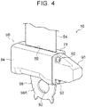
- the buckle device 10 includes a buckle body 50 to which the tongue portion 48 is to be connected, a webbing 54 (see FIG. 3 ) that is a strip-shaped member (connecting member), a force limiter mechanism 56, and a boot 82.
- the buckle body 50 is in the shape of a substantially rectangular block and is provided in the upper part of the buckle device 10.
- a retaining mechanism not shown, that retains the tongue portion 48
- a releasing mechanism not shown, that releases the tongue portion 48 from the retaining mechanism
- a frame 52 (see FIG. 3 ) having the retaining mechanism and the releasing mechanism attached thereto are provided in the buckle body 50.
- the frame 52 has a connecting portion 52A at its base end (lower end).
- One longitudinal end of the webbing 54 is connected to (retained by) the connecting portion 52A.
- the webbing 54 has a long strip shape, is made of a material similar to that of the seat belt 46, and is flexible.
- the one longitudinal end of the webbing 54 is wrapped around the connecting portion 52A, and both ends of the wrap around portion are sewn together.
- the other longitudinal end of the webbing 54 is retained by a spool 68 (see FIGS. 3 and 7 to 9 ) that is a take-up shaft of the force limiter mechanism 56.
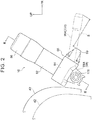
- the force limiter mechanism 56 includes, in addition to the spool 68, a frame 58, a bar 72, a protector 78, a cover 84, a torsion shaft (torsion bar) 86, and a case 90.
- the frame 58 is produced by, e.g., press drawing of a steel sheet.
- the frame 58 includes a back plate 58A. Leg portions 58B, 58C are extended approximately at right angles from both lateral ends of the upper part of the back plate 58A.
- the frame 58 thus has substantially a U-shape that is open on the outer side in the lateral direction of the vehicle seat 16 as viewed in plan.
- a long rectangular opening 60 is formed in an upper part of the back plate 58A and a circular attachment hole 62 is provided in a lower part of the back plate 58A.
- the leg portions 58B, 58C have circular bearing holes 64, 66, respectively.
- the bearing holes 64, 66 are formed coaxially and are adapted to the spool 68.
- the spool 68 is produced by, e.g., forging and has a substantially cylindrical shape. As shown in FIG. 9 , an axial intermediate portion of the spool 68 is a webbing retaining portion 68A having a substantially D-shaped section, and both axial ends of the spool 68 are shaft portions 68B, 68C having a circular section. The shaft portions 68B, 68C of the spool 68 are rotatably fitted in the bearing holes 64, 66 of the leg portions 58B, 58C. The spool 68 is thus supported by the frame 58 so as to be rotatable relative to the frame 58.
- reference character AX represents the axis of the spool 68.
- One shaft portion 68B of the spool 68 has a large diameter portion 68B 1 having a larger diameter than the bearing hole 64.
- the large diameter portion 68B1 is engaged with the edge of the bearing hole 64 from the opposite side of the leg portion 58B from the leg portion 58C.
- the spool 68 has a substantially C-shaped ring 70 fitted on the other shaft portion 68C.
- the ring 70 is engaged with the edge of the bearing hole 66 from the opposite side of the leg portion 58C from the leg portion 58B. This configuration restricts axial displacement of the spool 68 with respect to the frame 58.
- the other longitudinal end of the webbing 54 is wrapped around the webbing retaining portion 68A of the spool 68, and both ends of the wrap around portion of the webbing 54 are sewn together.
- the other longitudinal end of the webbing 54 is thus retained by the spool 68.
- the spool 68 has the cylindrical metal bar 72 attached thereto.
- the bar 72 restricts rotation of the webbing 54 relative to the spool 68.
- the bar 72 is attached parallel to the spool 68.
- Both axial ends of the bar 72 are fitted in grooves 74, 76 formed in the shaft portions 68B, 68C of the spool 68.
- Both axial ends of the bar 72 are located in the bearing holes 64, 66 of the frame 58 and are thus hindered from coming off from the grooves 74, 76.
- the other longitudinal end of the webbing 54 is wound around the spool 68, and the one longitudinal end of the webbing 54 extends upward from the spool 68.
- a longitudinal intermediate portion of the webbing 54 is inserted through a webbing insertion hole 80 formed in the protector 78.
- the protector 78 is, e.g., a resin molded article and is attached to the upper end of the frame 58 by claw fitting etc. The protector 78 prevents contact between the webbing 54 and the frame 58.
- the boot 82 is provided between the protector 78 and the buckle body 50.
- the boot 82 is made of, e.g., a soft resin or rubber and is in the shape of a long, substantially rectangular tube.
- the lower part of the buckle body 50 is fitted in one longitudinal end (upper end) of the boot 82, and the one longitudinal end portion of the webbing 54 is accommodated in the boot 82.
- the buckle body 50 is held standing by the boot 82.
- a part of the other longitudinal end of the webbing 54 wound around the spool 68 is placed in the opening 60 in the back plate 58A of the frame 58. This configuration reduces the thickness dimension of the force limiter mechanism 56 in the thickness direction of the back plate 58A.
- the cover 84 is attached to the upper part of the frame 58 from the opposite side of the frame 58 from the back plate 58A.
- the cover 84 is, e.g., a resin molded article and has a substantially U-shaped section that is open on the inner side in the lateral direction of the vehicle seat 16 as viewed in the axial direction of the spool 68.
- the cover 84 is attached to the frame 58 by claw fitting etc. and covers the spool 68 and the other longitudinal end of the webbing 54.
- the torsion shaft 86 which is the energy absorbing member, is placed on the opposite side of the one shaft portion 68B of the spool 68 from the webbing retaining portion 68A.
- the torsion shaft 86 is deformed by rotation of the spool 68.
- the torsion shaft 86 is formed in a substantially cylindrical shape by, e.g., forging and is coaxially disposed next to the spool 68 in the axial direction (the direction of the axis AX in FIG. 7 ).
- a length L (see FIG. 7 ) of the torsion shaft 86 is smaller than a lateral dimension W (see FIG. 7 ) of the webbing 54.
- Splines 86A, 86B are formed on both axial ends of the torsion shaft 86.
- the splines 86A on one axial end of the torsion shaft 86 are fitted in a spline hole 88 formed in the large diameter portion 68B1 of the shaft portion 68B of the spool 68.
- the one axial end of the torsion shaft 86 is thus connected to the spool 68 so as not to be rotatable relative to the spool 68.
- the splines 86B on the other axial end of the torsion shaft 86 are adapted to the case (force limiter case) 90.
- the case 90 is produced by die casing of, e.g., an aluminum alloy and is in the shape of a bottomed, substantially rectangular tube.
- the case 90 accommodates the torsion shaft 86 and is fixed to the leg portion 58B with a pair of screws 92.
- the case 90 has spline hole 89 (see FIG. 7 ) in its bottom wall, and the splines 86B on the other axial end of the torsion shaft 86 are fitted in the spline hole 89.
- the other axial end of the torsion shaft 86 is thus connected to the case 90 so as not to be rotatable relative to the case 90.
- the buckle device 10 including the force limiter mechanism 56 having the above configuration is mounted on the vehicle seat 16 via the anchor bracket 94.
- the anchor bracket 94 (not shown except FIGS. 1 and 3 ) is formed by, e.g., press forming a steel sheet and has an L-shaped section as viewed in the longitudinal direction of the vehicle.
- the anchor bracket 94 has a fixed wall, not shown, fixed to the upper surface of the rear part of the upper rail 28 and a vertical wall 94A extending upward from the outer end of the fixed wall in the lateral direction (the end on the middle side in the lateral direction of the vehicle) of the vehicle seat 16.
- the lower part of the frame 58 of the force limiter mechanism 56 is placed on the upper part of the vertical wall 94A from the outer side in the lateral direction of the vehicle seat 16.
- the vertical wall 94A has a through hole 96 in its upper part.
- the through hole 96 is concentric with the attachment hole 62 of the frame 58.
- a nut 100 is screwed on a stepped bolt 98 extending through the through hole 96 and the attachment hole 62.
- the axial direction of the stepped bolt 98 extends in the lateral direction of the vehicle, and the frame 58, namely the force limiter mechanism 56, is connected to the anchor bracket 94 so as to be rotatable relative to the anchor bracket 94 about the axis extending in the lateral direction of the vehicle.
- the spool 68 of the force limiter mechanism 56 is supported via the frame 58 so as to be rotatable relative to the vehicle seat 16.
- the force limiter mechanism 56 is located in front of the recliner cover 42 in the longitudinal direction of the vehicle.
- the spool 68 of the force limiter mechanism 56 is disposed in such an attitude that the axis of the spool 68 is perpendicular to the lateral direction of the vehicle (specifically, in an attitude tilted such that the front end of the spool 68 in the longitudinal direction of the vehicle is located lower than the rear end of the spool 68 in the longitudinal direction of the vehicle).
- the torsion shaft 86 covered by the case 90 is located in front of the spool 68 covered by the cover 84 in the longitudinal direction of the vehicle, namely is located on the opposite side of the spool 68 from the recliner cover 42.
- the recliner cover 42 is configured to be displaced between a lower position shown by a long dashed double-short dashed line in FIG. 2 and an upper position shown by a solid line in FIG. 2 by operation of the lifter mechanism 30.
- the load from the occupant P trying to move inertially toward the front side of the vehicle is applied to the buckle body 50 via the three-point seat belt 46 and the tongue portion 48.
- the one longitudinal end of the webbing 54 is connected to the buckle body 50.
- the other longitudinal end of the webbing 54 is wound around the spool 68 of the force limiter mechanism 56.
- the spool 68 is supported below the buckle body 50 in the vertical direction of the vehicle so as to be rotatable relative to the vehicle seat 16.
- the rotation of the spool 68 and the torsional deformation of the torsion shaft 86 stop when the portion of the webbing 54 wound around the spool 68 is completely pulled out.
- the load applied to the seat belt 46 is thereafter received by the vehicle body floor F via the spool 68, the frame 58, the anchor bracket 94, and the slide rails 24 until restraint of the occupant is finished.
- the force limiter mechanism 56 the amount by which the webbing 54 is pulled out from the spool 68 during shock absorption is equal to the displacement (shock absorption stroke) of the buckle body 50. That is, the amount by which the webbing 54 is wound around the spool 68 in a normal state is equal to the shock absorption stroke. Accordingly, an increase in size of the force limiter mechanism 56 which is associated with ensuring a sufficient shock absorption stroke is restrained as compared to a pipe type force limiter mechanism in which a cylindrical member becomes longer in proportion to the shock absorption stroke.
- reference character 204 indicates an example of the cylindrical member included in a conventional pipe type force limiter mechanism 202
- reference character S indicates reduction in size that can be achieved by the present embodiment as compared to the configuration having the a cylindrical member 204.
- the overall configuration of the buckle device 10 having the force limiter mechanism 56 is thus reduced in size as compared to conventional examples.
- the buckle device 10 thus has improved mountability on vehicles.
- pipe type force limiter mechanisms tend to be long in the longitudinal dimension of the vehicle.
- the present embodiment achieves significant reduction in dimension in the longitudinal direction of the vehicle.
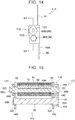
- a plurality of electrical wires 208 for supplying electric power to a vehicle seat are routed from a floor tunnel 210 side toward the vehicle seat side (toward the side shown by arrow LH in FIG. 10 ).
- the electrical wires 208 and a cover 212 that covers the electrical wires 208 are disposed between the floor tunnel 210 and the vehicle seat.
- interference between the cover 212 and the cylindrical member 204 is a problem when a buckle device 200 including the pipe type force limiter mechanism 202 is applied to such a vehicle.
- the present embodiment solves such a problem.
- the present embodiment is configured so that the torsion shaft 86 is torsionally deformed by the rotational force that acts on the spool 68, energy is efficiently absorbed by the small torsion shaft 86. That is, a required shock absorption stroke is obtained by the torsion shaft 86 even though the axial length of the torsion shaft 86 is smaller than that of the cylindrical member 204 shown in FIGS. 2 and 10 .
- the buckle device 10 is thus easily reduced in size.
- the torsion shaft 86 is coaxially disposed next to the spool 68 in the axial direction.
- the diameter of the spool 68 is therefore reduced as compared to the case where, e.g., the torsion shaft 86 is coaxially disposed in the spool 68.
- the thickness of the force limiter mechanism 56 in the radial direction of the spool 68 (in the present embodiment, the lateral direction of the vehicle) is reduced, which improves mountability of the buckle device 10 in narrow clearance on the lateral side of the vehicle seat 16.
- the spool 68 is supported below the buckle body 50 in the vertical direction of the vehicle so as to be rotatable relative to the vehicle seat 16, and the torsion shaft 86 is disposed in front of the spool 68 in the longitudinal direction of the vehicle.
- This configuration restrains degradation in mountability of the buckle device 10 on vehicles due to, e.g., interference between the torsion shaft 86 and the recliner cover 42 disposed behind the spool 68 in the longitudinal direction of the vehicle.
- the recliner cover 42 is displaced between the lower position shown by the long dashed double-short dashed line in FIG. 2 and the upper position shown by the solid line in FIG. 2 during operation of the lifter mechanism 30.
- the torsion shaft 86 and the case 90 are disposed on the opposite side of the force limiter mechanism 56 from the region in which the recliner cover 42 is displaced. This configuration eliminates the need to consider the interference between the recliner cover 42 and the torsion shaft 86 when mounting the buckle device 10 on the vehicle seat 16.
- the one longitudinal end of the webbing 54 that is the connecting member is connected to the buckle body 50, and the other longitudinal end of the webbing 54 is wound around the spool 68 of the force limiter mechanism 56. Since the webbing 54 is flexible and has a long strip shape, it is more easily ensured that the webbing 54 has sufficient resistance to bending as compared to the case where the connecting member is a wire (wire rope). For example, in the structure in which a wire is connected to a buckle body as in the buckle device disclosed in Japanese Patent Application Publication No.
- a part of the wire may be bent and stress may be applied to strands of the wire when an occupant P accidentally sits on the buckle body 50 when getting into the vehicle etc.
- the webbing 54 made of a material similar to that of the seat belt 46 is connected to the buckle body 50, it is easily ensured that the webbing 54 has resistance to bending, and the webbing 54 is therefore easy to handle.
- the webbing 54 can be wound around the spool 68 with a smaller winding diameter as compared to such a wire as described above. This also contributes to the reduction in thickness described above.
- the length L of the torsion shaft 86 is smaller than the lateral dimension W of the webbing 54. This configuration achieves further reduction in size of the buckle device 10 and thus further improves the mountability of the buckle device 10 in the narrow clearance on the lateral side of the vehicle seat 16.
- the webbing 54 that is the strip-shaped member is produced using a material similar to that of the seat belt 46.
- the invention is not limited to this.
- a film-like strip-shaped member that is thinner than the seat belt 46 may be produced using a material having sufficient strength such as "Kevlar (registered trademark)."
- the strip-shaped member can be wound around the spool 68 (take-up shaft) with a smaller winding diameter, and further reduction in size of the buckle device 10 is achieved.
- the connecting member is not limited to the webbing 54 (strip-shaped member) but may be a wire (wire rope) etc.
- the spool 68 and the bar 72 are produced as separate parts, and the spool 68 and the torsion shaft 86 are produced as separate parts.
- the spool 68 and the bar 72 may be produced as a single-piece part, and the spool 68 and the torsion shaft 86 may be produced as a single-piece part.
- the torsion shaft 86 is coaxially displaced next to the spool 68 in the axial direction.
- the invention is not limited to this, and the torsion shaft 86 may be coaxially displaced in the spool 68.
- the frame 58 and the case 90 are produced as separate parts.
- the frame 58 and the case 90 may be produced as a single-piece part.
- each of the frame 58 and the case 90 may be comprised of a plurality of parts.
- the frame 58 is not limited to the one produced by press drawing etc.
- the frame 58 may be comprised of a plurality of parts or may be an extended portion of a frame of the vehicle seat 16.
- the spool 68 and the other longitudinal end portion of the webbing 54 wound around the spool 68 are covered by the cover 84.
- the cover 84 may be omitted.
- a cover that covers either the entire force limiter mechanism 56 including the frame 58 and the case 90 or most of the force limiter mechanism 56 or a cover that continuously covers from the buckle body 50 to the force limiter mechanism 56 may be provided to enhance appearance.
- the frame 58, the spool 68, the bar 72, and the case 90 are made of a metal.
- the invention is not limited to this, and these members may be made of a resin (e.g., fiber-reinforced resin) that is lighter than metals.
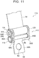
- FIG. 11 is a perspective view of a force limiter mechanism 112 included in a buckle device 110 according to a second embodiment of the invention.
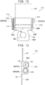
- FIG. 12 is a side view of the force limiter mechanism 112
- FIG. 13 is a rear view of the force limiter mechanism 112
- FIG. 14 is a front view of the force limiter mechanism 112.
- FIG. 15 is an enlarged sectional view taken along line XV-XV in FIG. 14
- FIG. 16 is an exploded perspective view of the force limiter mechanism 112.
- the force limiter mechanism 112 of the buckle device 110 includes a spur gear train 114 that transmits rotation of the spool 68 to the torsion shaft 86.
- the torsion shaft 86 is disposed parallel to the spool 68.
- the shaft portions 68B, 68C are formed at both axial ends of the spool 68, and the shaft portions 68B, 68C are rotatably fitted in the bearing holes 64, 66 of the frame 58, so that the spool 68 is supported by the frame 58 so as to be rotatable relative to the frame 58.
- Plate-like fixing portions 68D, 68E are formed at both axial ends of the spool 68 in order to fix a spur gear 116 and a retaining member 120 thereto.
- the spur gear 116 and the retaining member 120 are disposed coaxially with the spool 68, and the fixing portions 68D, 68E are press-fitted in fixing holes 117, 121 (see FIG.
- the torsion shaft 86 is longer than the torsion shaft 86 according to the first embodiment and is disposed below the spool 68 in an attitude parallel to the spool 68.
- the splines 86B on the other axial end of the torsion shaft 86 are fitted in a spline hole 122 formed in the leg portion 58B of the frame 58.
- the one axial end portion of the torsion shaft 86 is rotatably fitted in a circular bearing hole 124 formed in the leg portion 58C of the frame 58.
- the splines 86A on the one axial end of the torsion shaft 86 are disposed on the opposite side of the leg portion 58C from the leg portion 58B and are adapted to a spur gear 118.
- the spur gear 118 is disposed coaxially with the torsion shaft 86, and the splines 86A are press-fitted in a spline hole 126 formed in the center of the spur gear 118.
- the spur gear 118 is thus fixed to the one axial end of the torsion shaft 86.
- the spur gear 118 meshes with the spur gear 116. Rotation of the spool 68 is thus transmitted to the torsion shaft 86 via the spur gears 116, 118, that is, via the spur gear train 114.
- the configuration of the present embodiment is otherwise similar to that of the first embodiment. Accordingly, the present embodiment also improves mountability of the buckle device 110 on vehicles like the first embodiment. Since the force limiter mechanism 112 has the spur gear train 114, the torsion shaft 86 can be disposed on an axis other than the axis of the spool 68. Flexibility in positioning of the torsion shaft 86 is thus improved. Moreover, the torsion shaft 86 is disposed below and parallel to the spool 68.
- the force limiter mechanism 112 is reduced in thickness in the lateral direction of the vehicle (the thickness direction of the back plate 58A), and is also reduced in size in the longitudinal direction of the vehicle as compared to the force limiter mechanism 56 according to the first embodiment.
- the spool 68 and the torsion shaft 86 may be switched in position in the vertical direction.
- the spool 68 and the torsion shaft 86 may be disposed so as to sandwich the attachment hole 62 of the frame 58 in the vertical direction as viewed in the lateral direction of the vehicle seat 16 (the attachment hole 62 may be located between the spool 68 and the torsion shaft 86 as viewed in the lateral direction of the vehicle seat 16).
- FIG. 17 is a side view of a force limiter mechanism 132 included in a buckle device 130 according to a third embodiment of the invention.
- the force limiter mechanism 132 has a bevel gear train 134 that transmits rotation of the spool 68 to the torsion shaft 86, and the torsion shaft 86 is disposed perpendicularly to the spool 68.
- the torsion shaft 86 is supported by a pair of upper and lower support portions 140, 142 extended from the leg portion 58C of the frame 58.
- the upper support portion 140 has a circular through hole (not shown) in which one axial end portion of the torsion shaft 86 is rotatably fitted.
- the lower support portion 142 has a spline hole, not shown, in which the splines 86B on the other axial end of the torsion shaft 86 are fitted.
- the splines 86A (not shown in FIG. 17 ) on the one axial end of the torsion shaft 86 are press-fitted in a spline hole, not shown, formed in the center of a bevel gear 138.
- the bevel gear 138 is disposed coaxially with the torsion shaft 86 and meshes with another bevel gear 136 disposed coaxially with the spool 68.
- the fixing portion 68E of the spool 68 is press-fitted in a fixing hole, not shown, formed in the center of the bevel gear 136, so that the bevel gear 136 is fixed to the spool 68. Rotation of the spool 68 is thus transmitted to the torsion shaft 86 via the bevel gears 136, 138, that is, via the bevel gear train 134.
- the configuration of the present embodiment is otherwise similar to that of the first embodiment. Accordingly, the present embodiment also improves mountability of the buckle device 130 on vehicles like the first embodiment. Since the force limiter mechanism 132 has the bevel gear train 134, flexibility in positioning of the torsion shaft 86 with respect to the spool 68 is improved and mountability of the buckle device 130 on various vehicles is improved. Since the torsion shaft 86 is disposed perpendicularly to the spool 68, the dimension of the force limiter mechanism 132 in the axial direction of the spool 68 is reduced.
- FIG. 18 is an exploded perspective view of a force limiter mechanism 152 of a buckle device 150 according to a fourth embodiment of the invention.
- the force limiter mechanism 152 is a wire type force limiter mechanism.
- stepped bolts 154, 156 are rotatably inserted through the bearing holes 64, 66 of the leg portions 58B, 58C of the frame 58.
- the stepped bolts 154, 156 are screwed into threaded holes 158 formed in both axial ends of the spool 68.
- the spool 68 is thus supported by the frame 58 so as to be rotatable relative to the frame 58.
- a guide groove 160 is formed on one axial end face of the spool 68.
- the guide groove 160 has a ring shape concentric with the spool 68.
- the leg portion 58C of the frame 58 has a fixing hole 162 formed at a position facing the guide groove 160 and extending through the leg portion 58C.
- the spool 68 further has a fitting insertion hole 164.
- the fitting insertion hole 164 is a bottomed hole that is open to the bottom surface of the guide groove 160.
- the fitting insertion hole 164 extends in the axial direction of the spool 68.
- the fixing hole 162, the guide groove 160, and the fitting insertion hole 164 are adapted to a wire 168 that is the energy absorbing member.
- the wire 168 is made of, e.g., a linear steel material formed in the shape of a wire.
- the wire 168 includes a curved portion 168A disposed in the guide groove 160.
- the curved portion 168A is curved like a bow according to the curvature of the guide groove 160.
- a fixing portion 168B is extended from one end of the curved portion 168A toward the opposite side from the spool 68.
- the fixing portion 168B is inserted through the fixing hole 162, and a head portion 168B1 formed on the tip end portion of the fixing portion 168B is engaged with the edge of the fixing hole 162.
- the fixing portion 168B is thus fixed to the frame 58.
- a fitting insertion portion 168C is extended from the other end of the curved portion 168A toward the spool 68 side.
- the fitting insertion portion 168C is slidably inserted in the fitting insertion hole 164.
- the webbing 54 (not shown in FIG. 18 ) wound around the spool 68 is pulled by the load applied from the occupant P in case of a collision of the vehicle.
- the fitting insertion portion 168C of the wire 168 fittingly inserted in the fitting insertion hole 164 of the spool 68 is pulled out of the fitting insertion hole 164 while being in frictional contact with (deformed by) the opening edge of the fitting insertion hole 164, the leg portion 58C of the frame 58, and the inner wall surface of the guide groove 160.
- the load provided for the frictional contact (deformation) of the fitting insertion portion 168C is applied to the seat belt 46 as a force limiter load. Shock applied from the seat belt 46 to the occupant P is thus absorbed.
- the configuration of the present embodiment is otherwise similar to that of the first embodiment. Accordingly, the present embodiment also improves mountability of the buckle device 150 on vehicles like the first embodiment.
Landscapes
- Engineering & Computer Science (AREA)
- Mechanical Engineering (AREA)
- General Engineering & Computer Science (AREA)
- Aviation & Aerospace Engineering (AREA)
- Transportation (AREA)
- Automotive Seat Belt Assembly (AREA)
- Buckles (AREA)
Applications Claiming Priority (1)
| Application Number | Priority Date | Filing Date | Title |
|---|---|---|---|
| JP2019018267A JP7132141B2 (ja) | 2019-02-04 | 2019-02-04 | バックル装置、バックル装置のシート搭載構造、及び車両用シートベルト装置 |
Publications (2)
| Publication Number | Publication Date |
|---|---|
| EP3689685A1 true EP3689685A1 (de) | 2020-08-05 |
| EP3689685B1 EP3689685B1 (de) | 2021-12-29 |
Family
ID=69147467
Family Applications (1)
| Application Number | Title | Priority Date | Filing Date |
|---|---|---|---|
| EP20150538.5A Active EP3689685B1 (de) | 2019-02-04 | 2020-01-07 | Schnallenvorrichtung, sitzbefestigungsstruktur für eine schnallenvorrichtung und fahrzeugsicherheitsgurtvorrichtung |
Country Status (5)
| Country | Link |
|---|---|
| US (1) | US11135997B2 (de) |
| EP (1) | EP3689685B1 (de) |
| JP (1) | JP7132141B2 (de) |
| KR (1) | KR102305515B1 (de) |
| CN (1) | CN111516635B (de) |
Families Citing this family (5)
| Publication number | Priority date | Publication date | Assignee | Title |
|---|---|---|---|---|
| KR102446335B1 (ko) * | 2021-04-16 | 2022-09-22 | 현대트랜시스 주식회사 | 차량용 워크-인 시트의 록킹 장치 |
| JP2022189176A (ja) | 2021-06-10 | 2022-12-22 | 株式会社東海理化電機製作所 | バックル装置 |
| US20220396236A1 (en) * | 2021-06-10 | 2022-12-15 | Kabushiki Kaisha Tokai-Rika-Denki-Seisakusho | Buckle device |
| JP7348935B2 (ja) | 2021-08-26 | 2023-09-21 | 株式会社東海理化電機製作所 | バックル装置 |
| KR20230153639A (ko) | 2022-04-29 | 2023-11-07 | (주)대한솔루션 | 사용하지 않을 때 소음 발생을 줄일 수 있는 자동차용 3점식 안전벨트 |
Citations (6)
| Publication number | Priority date | Publication date | Assignee | Title |
|---|---|---|---|---|
| JPH10100860A (ja) | 1996-09-26 | 1998-04-21 | Suncall Corp | 自動車用シートベルトの緩衝装置 |
| US6302346B1 (en) * | 2000-01-14 | 2001-10-16 | Trw Vehicle Safety Systems Inc. | Seat belt webbing energy management device |
| JP2001322531A (ja) | 2000-05-15 | 2001-11-20 | Takata Corp | バックル装置 |
| DE102013001375A1 (de) * | 2013-01-28 | 2014-07-31 | Autoliv Development Ab | Gurtschlosskraftreduzierungsvorrichtung, Verfahren zum Reduzieren einer im Lastfall auf ein Gurtschloss einwirkenden Kraft sowie eine Verwendung |
| DE102016015161A1 (de) * | 2016-12-20 | 2017-05-24 | Daimler Ag | Gurtkraftbegrenzer |
| US20180319361A1 (en) * | 2017-05-03 | 2018-11-08 | Ford Global Technologies, Llc | Energy-absorbing restraint system |
Family Cites Families (29)
| Publication number | Priority date | Publication date | Assignee | Title |
|---|---|---|---|---|
| JPS5825156U (ja) * | 1981-08-12 | 1983-02-17 | トヨタ自動車株式会社 | シ−トベルト引締め装置 |
| JPS61158550U (de) * | 1985-03-25 | 1986-10-01 | ||
| DE19511457A1 (de) | 1995-03-29 | 1996-10-02 | Trw Repa Gmbh | Kraftbegrenzung in einem Insassen-Rückhaltesystem |
| DE29610078U1 (de) * | 1996-06-07 | 1996-10-02 | Trw Repa Gmbh | Rückhaltesystem für Fahrzeuginsassen |
| KR100228125B1 (ko) | 1996-12-31 | 1999-11-01 | 정몽규 | 길이조정이 가능한 시트벨트 버클구조 |
| DE19747461A1 (de) * | 1997-10-27 | 1999-04-29 | Takata Europ Gmbh | Gurtaufroller |
| US6056320A (en) * | 1998-10-23 | 2000-05-02 | Chrysler Corporation | Energy absorbing occupant restraint system |
| GB2354209B (en) * | 1999-09-17 | 2001-12-05 | Breed Automotive Tech | Safety restraint |
| JP4231185B2 (ja) * | 2000-03-21 | 2009-02-25 | 株式会社東海理化電機製作所 | ウェビング巻取装置 |
| FR2819465B1 (fr) * | 2001-01-12 | 2003-03-07 | Peugeot Citroen Automobiles Sa | Brin boucle de ceinture de securite, notamment pour vehicule automobile |
| DE20102758U1 (de) | 2001-02-16 | 2001-06-28 | Trw Repa Gmbh | Gurtstraffer |
| JP3919653B2 (ja) | 2002-11-08 | 2007-05-30 | エヌエスケー・オートリブ株式会社 | シートベルト装置 |
| FR2922483B1 (fr) * | 2007-10-23 | 2010-04-09 | Peugeot Citroen Automobiles Sa | Boucle escamotable pour ceinture de securite. |
| DE112009001995A5 (de) * | 2008-08-22 | 2011-09-29 | Inventus Engineering Gmbh | Bewegung dämpfende Vorrichtung |
| DE102008052332A1 (de) * | 2008-10-20 | 2010-04-22 | Trw Automotive Gmbh | Baugruppe mit einer Achse und einer auf der Achse angeordneten Feder sowie Vorrichtung zur Befestigung eines Sicherheitsgurtschlosses |
| JP5849938B2 (ja) * | 2012-12-04 | 2016-02-03 | トヨタ自動車株式会社 | シートベルトのバックル構造 |
| JP5986152B2 (ja) * | 2014-07-30 | 2016-09-06 | トヨタ自動車株式会社 | リフトアップバックル装置 |
| WO2016031287A1 (ja) * | 2014-08-28 | 2016-03-03 | 河西工業株式会社 | シートベルトアンカーボルト付近の衝撃吸収構造 |
| JP2016107867A (ja) * | 2014-12-08 | 2016-06-20 | 株式会社東海理化電機製作所 | ウェビング巻取装置 |
| US9821758B2 (en) * | 2016-02-05 | 2017-11-21 | Ford Global Technologies, Llc | Pretensioning, force-limiting seat belt assembly |
| US9827947B2 (en) * | 2016-02-10 | 2017-11-28 | Ford Global Technologies, Llc | Load limiting seat belt buckle assemblies |
| JP6361675B2 (ja) * | 2016-03-08 | 2018-07-25 | マツダ株式会社 | 車両用シート |
| JP6410748B2 (ja) * | 2016-03-08 | 2018-10-24 | 本田技研工業株式会社 | シートベルト装置 |
| TWI606943B (zh) * | 2016-12-16 | 2017-12-01 | liang xiong Wang | Safety belt guide ring device |
| US11338764B2 (en) * | 2016-12-30 | 2022-05-24 | Key Safety Systems Inc. | Restraining system for a seat belt buckle |
| US10064452B1 (en) * | 2017-06-30 | 2018-09-04 | Ford Global Technologies, Llc | Seatbelt tongue |
| JP6891742B2 (ja) * | 2017-09-05 | 2021-06-18 | トヨタ自動車株式会社 | 3点式シートベルト装置 |
| US10543807B2 (en) * | 2018-01-03 | 2020-01-28 | Ford Global Technologies, Llc | Energy absorbing restraint system |
| JP7095492B2 (ja) * | 2018-08-27 | 2022-07-05 | トヨタ自動車株式会社 | 車両用シート |
-
2019
- 2019-02-04 JP JP2019018267A patent/JP7132141B2/ja active Active
-
2020
- 2020-01-07 EP EP20150538.5A patent/EP3689685B1/de active Active
- 2020-01-08 US US16/737,121 patent/US11135997B2/en active Active
- 2020-01-09 KR KR1020200002947A patent/KR102305515B1/ko active IP Right Grant
- 2020-01-23 CN CN202010076579.5A patent/CN111516635B/zh active Active
Patent Citations (6)
| Publication number | Priority date | Publication date | Assignee | Title |
|---|---|---|---|---|
| JPH10100860A (ja) | 1996-09-26 | 1998-04-21 | Suncall Corp | 自動車用シートベルトの緩衝装置 |
| US6302346B1 (en) * | 2000-01-14 | 2001-10-16 | Trw Vehicle Safety Systems Inc. | Seat belt webbing energy management device |
| JP2001322531A (ja) | 2000-05-15 | 2001-11-20 | Takata Corp | バックル装置 |
| DE102013001375A1 (de) * | 2013-01-28 | 2014-07-31 | Autoliv Development Ab | Gurtschlosskraftreduzierungsvorrichtung, Verfahren zum Reduzieren einer im Lastfall auf ein Gurtschloss einwirkenden Kraft sowie eine Verwendung |
| DE102016015161A1 (de) * | 2016-12-20 | 2017-05-24 | Daimler Ag | Gurtkraftbegrenzer |
| US20180319361A1 (en) * | 2017-05-03 | 2018-11-08 | Ford Global Technologies, Llc | Energy-absorbing restraint system |
Also Published As
| Publication number | Publication date |
|---|---|
| US11135997B2 (en) | 2021-10-05 |
| CN111516635B (zh) | 2022-06-14 |
| CN111516635A (zh) | 2020-08-11 |
| JP7132141B2 (ja) | 2022-09-06 |
| KR102305515B1 (ko) | 2021-09-27 |
| US20200247352A1 (en) | 2020-08-06 |
| JP2020125010A (ja) | 2020-08-20 |
| EP3689685B1 (de) | 2021-12-29 |
| KR20200096415A (ko) | 2020-08-12 |
Similar Documents
| Publication | Publication Date | Title |
|---|---|---|
| EP3689685B1 (de) | Schnallenvorrichtung, sitzbefestigungsstruktur für eine schnallenvorrichtung und fahrzeugsicherheitsgurtvorrichtung | |
| US7472963B2 (en) | Recliner lever assembly for a front seat of a vehicle | |
| US5967604A (en) | Vehicle seat apparatus | |
| CN110861550B (zh) | 车辆用座椅 | |
| JP5308010B2 (ja) | 車両用シート | |
| EP2347929B1 (de) | Sitzlehnenrahmenstruktur eines Sitzes für Fahrzeug und Sitz für Fahrzeug mit Sitzlehnenrahmenstruktur | |
| US20090167066A1 (en) | Seat apparatus for vehicle | |
| WO2012086803A1 (ja) | 乗物用シート | |
| EP2492158B1 (de) | Sitzgurtanordnung | |
| EP2644443B1 (de) | Fahrzeugsitz | |
| JP6270296B2 (ja) | 自動車用シート | |
| JP2006526536A (ja) | 車両座席用のベルトロック装置 | |
| EP3521112B1 (de) | Fahrzeuginsassenrückhaltevorrichtung | |
| US8276983B2 (en) | Manual retracting head restraint | |
| JP2010179753A (ja) | 乗物用シート | |
| JP2018090224A (ja) | シートベルト内蔵車両用シート | |
| JP4222235B2 (ja) | シート | |
| US20220153176A1 (en) | Headrest assembly with slidable ratchet mechanism | |
| JP4353488B2 (ja) | シートベルト用アンカープレートの取付構造 | |
| US11548472B2 (en) | Seat belt assembly | |
| JP7235413B2 (ja) | ラッププリテンショナを備えた車両用シート装置 | |
| KR19990080019A (ko) | 자동차시트의 람버 서포트 | |
| CN114616138A (zh) | 用于车辆的安全带系统和具有安全带系统的车辆 | |
| GB2339145A (en) | A vehicle seat | |
| KR20030013821A (ko) | 자동차용 시트벨트 버클 |
Legal Events
| Date | Code | Title | Description |
|---|---|---|---|
| PUAI | Public reference made under article 153(3) epc to a published international application that has entered the european phase |
Free format text: ORIGINAL CODE: 0009012 |
|
| STAA | Information on the status of an ep patent application or granted ep patent |
Free format text: STATUS: REQUEST FOR EXAMINATION WAS MADE |
|
| 17P | Request for examination filed |
Effective date: 20200107 |
|
| AK | Designated contracting states |
Kind code of ref document: A1 Designated state(s): AL AT BE BG CH CY CZ DE DK EE ES FI FR GB GR HR HU IE IS IT LI LT LU LV MC MK MT NL NO PL PT RO RS SE SI SK SM TR |
|
| AX | Request for extension of the european patent |
Extension state: BA ME |
|
| GRAP | Despatch of communication of intention to grant a patent |
Free format text: ORIGINAL CODE: EPIDOSNIGR1 |
|
| STAA | Information on the status of an ep patent application or granted ep patent |
Free format text: STATUS: GRANT OF PATENT IS INTENDED |
|
| INTG | Intention to grant announced |
Effective date: 20210812 |
|
| GRAS | Grant fee paid |
Free format text: ORIGINAL CODE: EPIDOSNIGR3 |
|
| GRAA | (expected) grant |
Free format text: ORIGINAL CODE: 0009210 |
|
| STAA | Information on the status of an ep patent application or granted ep patent |
Free format text: STATUS: THE PATENT HAS BEEN GRANTED |
|
| AK | Designated contracting states |
Kind code of ref document: B1 Designated state(s): AL AT BE BG CH CY CZ DE DK EE ES FI FR GB GR HR HU IE IS IT LI LT LU LV MC MK MT NL NO PL PT RO RS SE SI SK SM TR |
|
| REG | Reference to a national code |
Ref country code: GB Ref legal event code: FG4D |
|
| REG | Reference to a national code |
Ref country code: CH Ref legal event code: EP |
|
| REG | Reference to a national code |
Ref country code: AT Ref legal event code: REF Ref document number: 1458458 Country of ref document: AT Kind code of ref document: T Effective date: 20220115 |
|
| REG | Reference to a national code |
Ref country code: IE Ref legal event code: FG4D |
|
| REG | Reference to a national code |
Ref country code: DE Ref legal event code: R096 Ref document number: 602020001394 Country of ref document: DE |
|
| REG | Reference to a national code |
Ref country code: LT Ref legal event code: MG9D |
|
| PG25 | Lapsed in a contracting state [announced via postgrant information from national office to epo] |
Ref country code: RS Free format text: LAPSE BECAUSE OF FAILURE TO SUBMIT A TRANSLATION OF THE DESCRIPTION OR TO PAY THE FEE WITHIN THE PRESCRIBED TIME-LIMIT Effective date: 20211229 Ref country code: LT Free format text: LAPSE BECAUSE OF FAILURE TO SUBMIT A TRANSLATION OF THE DESCRIPTION OR TO PAY THE FEE WITHIN THE PRESCRIBED TIME-LIMIT Effective date: 20211229 Ref country code: FI Free format text: LAPSE BECAUSE OF FAILURE TO SUBMIT A TRANSLATION OF THE DESCRIPTION OR TO PAY THE FEE WITHIN THE PRESCRIBED TIME-LIMIT Effective date: 20211229 Ref country code: BG Free format text: LAPSE BECAUSE OF FAILURE TO SUBMIT A TRANSLATION OF THE DESCRIPTION OR TO PAY THE FEE WITHIN THE PRESCRIBED TIME-LIMIT Effective date: 20220329 |
|
| REG | Reference to a national code |
Ref country code: NL Ref legal event code: MP Effective date: 20211229 |
|
| REG | Reference to a national code |
Ref country code: AT Ref legal event code: MK05 Ref document number: 1458458 Country of ref document: AT Kind code of ref document: T Effective date: 20211229 |
|
| PG25 | Lapsed in a contracting state [announced via postgrant information from national office to epo] |
Ref country code: SE Free format text: LAPSE BECAUSE OF FAILURE TO SUBMIT A TRANSLATION OF THE DESCRIPTION OR TO PAY THE FEE WITHIN THE PRESCRIBED TIME-LIMIT Effective date: 20211229 Ref country code: NO Free format text: LAPSE BECAUSE OF FAILURE TO SUBMIT A TRANSLATION OF THE DESCRIPTION OR TO PAY THE FEE WITHIN THE PRESCRIBED TIME-LIMIT Effective date: 20220329 Ref country code: LV Free format text: LAPSE BECAUSE OF FAILURE TO SUBMIT A TRANSLATION OF THE DESCRIPTION OR TO PAY THE FEE WITHIN THE PRESCRIBED TIME-LIMIT Effective date: 20211229 Ref country code: HR Free format text: LAPSE BECAUSE OF FAILURE TO SUBMIT A TRANSLATION OF THE DESCRIPTION OR TO PAY THE FEE WITHIN THE PRESCRIBED TIME-LIMIT Effective date: 20211229 Ref country code: GR Free format text: LAPSE BECAUSE OF FAILURE TO SUBMIT A TRANSLATION OF THE DESCRIPTION OR TO PAY THE FEE WITHIN THE PRESCRIBED TIME-LIMIT Effective date: 20220330 |
|
| PGFP | Annual fee paid to national office [announced via postgrant information from national office to epo] |
Ref country code: FR Payment date: 20220127 Year of fee payment: 3 |
|
| PG25 | Lapsed in a contracting state [announced via postgrant information from national office to epo] |
Ref country code: NL Free format text: LAPSE BECAUSE OF FAILURE TO SUBMIT A TRANSLATION OF THE DESCRIPTION OR TO PAY THE FEE WITHIN THE PRESCRIBED TIME-LIMIT Effective date: 20211229 |
|
| PG25 | Lapsed in a contracting state [announced via postgrant information from national office to epo] |
Ref country code: SM Free format text: LAPSE BECAUSE OF FAILURE TO SUBMIT A TRANSLATION OF THE DESCRIPTION OR TO PAY THE FEE WITHIN THE PRESCRIBED TIME-LIMIT Effective date: 20211229 Ref country code: SK Free format text: LAPSE BECAUSE OF FAILURE TO SUBMIT A TRANSLATION OF THE DESCRIPTION OR TO PAY THE FEE WITHIN THE PRESCRIBED TIME-LIMIT Effective date: 20211229 Ref country code: RO Free format text: LAPSE BECAUSE OF FAILURE TO SUBMIT A TRANSLATION OF THE DESCRIPTION OR TO PAY THE FEE WITHIN THE PRESCRIBED TIME-LIMIT Effective date: 20211229 Ref country code: PT Free format text: LAPSE BECAUSE OF FAILURE TO SUBMIT A TRANSLATION OF THE DESCRIPTION OR TO PAY THE FEE WITHIN THE PRESCRIBED TIME-LIMIT Effective date: 20220429 Ref country code: ES Free format text: LAPSE BECAUSE OF FAILURE TO SUBMIT A TRANSLATION OF THE DESCRIPTION OR TO PAY THE FEE WITHIN THE PRESCRIBED TIME-LIMIT Effective date: 20211229 Ref country code: EE Free format text: LAPSE BECAUSE OF FAILURE TO SUBMIT A TRANSLATION OF THE DESCRIPTION OR TO PAY THE FEE WITHIN THE PRESCRIBED TIME-LIMIT Effective date: 20211229 Ref country code: CZ Free format text: LAPSE BECAUSE OF FAILURE TO SUBMIT A TRANSLATION OF THE DESCRIPTION OR TO PAY THE FEE WITHIN THE PRESCRIBED TIME-LIMIT Effective date: 20211229 |
|
| PG25 | Lapsed in a contracting state [announced via postgrant information from national office to epo] |
Ref country code: PL Free format text: LAPSE BECAUSE OF FAILURE TO SUBMIT A TRANSLATION OF THE DESCRIPTION OR TO PAY THE FEE WITHIN THE PRESCRIBED TIME-LIMIT Effective date: 20211229 Ref country code: AT Free format text: LAPSE BECAUSE OF FAILURE TO SUBMIT A TRANSLATION OF THE DESCRIPTION OR TO PAY THE FEE WITHIN THE PRESCRIBED TIME-LIMIT Effective date: 20211229 |
|
| PG25 | Lapsed in a contracting state [announced via postgrant information from national office to epo] |
Ref country code: MC Free format text: LAPSE BECAUSE OF FAILURE TO SUBMIT A TRANSLATION OF THE DESCRIPTION OR TO PAY THE FEE WITHIN THE PRESCRIBED TIME-LIMIT Effective date: 20211229 Ref country code: IS Free format text: LAPSE BECAUSE OF FAILURE TO SUBMIT A TRANSLATION OF THE DESCRIPTION OR TO PAY THE FEE WITHIN THE PRESCRIBED TIME-LIMIT Effective date: 20220429 |
|
| REG | Reference to a national code |
Ref country code: DE Ref legal event code: R097 Ref document number: 602020001394 Country of ref document: DE |
|
| REG | Reference to a national code |
Ref country code: BE Ref legal event code: MM Effective date: 20220131 |
|
| PG25 | Lapsed in a contracting state [announced via postgrant information from national office to epo] |
Ref country code: LU Free format text: LAPSE BECAUSE OF NON-PAYMENT OF DUE FEES Effective date: 20220107 Ref country code: DK Free format text: LAPSE BECAUSE OF FAILURE TO SUBMIT A TRANSLATION OF THE DESCRIPTION OR TO PAY THE FEE WITHIN THE PRESCRIBED TIME-LIMIT Effective date: 20211229 Ref country code: AL Free format text: LAPSE BECAUSE OF FAILURE TO SUBMIT A TRANSLATION OF THE DESCRIPTION OR TO PAY THE FEE WITHIN THE PRESCRIBED TIME-LIMIT Effective date: 20211229 |
|
| PLBE | No opposition filed within time limit |
Free format text: ORIGINAL CODE: 0009261 |
|
| STAA | Information on the status of an ep patent application or granted ep patent |
Free format text: STATUS: NO OPPOSITION FILED WITHIN TIME LIMIT |
|
| PG25 | Lapsed in a contracting state [announced via postgrant information from national office to epo] |
Ref country code: BE Free format text: LAPSE BECAUSE OF NON-PAYMENT OF DUE FEES Effective date: 20220131 |
|
| 26N | No opposition filed |
Effective date: 20220930 |
|
| PG25 | Lapsed in a contracting state [announced via postgrant information from national office to epo] |
Ref country code: IE Free format text: LAPSE BECAUSE OF NON-PAYMENT OF DUE FEES Effective date: 20220107 |
|
| PG25 | Lapsed in a contracting state [announced via postgrant information from national office to epo] |
Ref country code: SI Free format text: LAPSE BECAUSE OF FAILURE TO SUBMIT A TRANSLATION OF THE DESCRIPTION OR TO PAY THE FEE WITHIN THE PRESCRIBED TIME-LIMIT Effective date: 20211229 |
|
| PG25 | Lapsed in a contracting state [announced via postgrant information from national office to epo] |
Ref country code: IT Free format text: LAPSE BECAUSE OF FAILURE TO SUBMIT A TRANSLATION OF THE DESCRIPTION OR TO PAY THE FEE WITHIN THE PRESCRIBED TIME-LIMIT Effective date: 20211229 |
|
| REG | Reference to a national code |
Ref country code: CH Ref legal event code: PL |
|
| PG25 | Lapsed in a contracting state [announced via postgrant information from national office to epo] |
Ref country code: LI Free format text: LAPSE BECAUSE OF NON-PAYMENT OF DUE FEES Effective date: 20230131 Ref country code: CH Free format text: LAPSE BECAUSE OF NON-PAYMENT OF DUE FEES Effective date: 20230131 |
|
| PG25 | Lapsed in a contracting state [announced via postgrant information from national office to epo] |
Ref country code: FR Free format text: LAPSE BECAUSE OF NON-PAYMENT OF DUE FEES Effective date: 20230131 |
|
| REG | Reference to a national code |
Ref country code: DE Ref legal event code: R084 Ref document number: 602020001394 Country of ref document: DE |
|
| PG25 | Lapsed in a contracting state [announced via postgrant information from national office to epo] |
Ref country code: MK Free format text: LAPSE BECAUSE OF FAILURE TO SUBMIT A TRANSLATION OF THE DESCRIPTION OR TO PAY THE FEE WITHIN THE PRESCRIBED TIME-LIMIT Effective date: 20211229 Ref country code: CY Free format text: LAPSE BECAUSE OF FAILURE TO SUBMIT A TRANSLATION OF THE DESCRIPTION OR TO PAY THE FEE WITHIN THE PRESCRIBED TIME-LIMIT Effective date: 20211229 |
|
| PGFP | Annual fee paid to national office [announced via postgrant information from national office to epo] |
Ref country code: DE Payment date: 20231128 Year of fee payment: 5 |