EP3689193B1 - Cooking vessel device applicable to fully automated stir fry machine - Google Patents
Cooking vessel device applicable to fully automated stir fry machine Download PDFInfo
- Publication number
- EP3689193B1 EP3689193B1 EP17930285.6A EP17930285A EP3689193B1 EP 3689193 B1 EP3689193 B1 EP 3689193B1 EP 17930285 A EP17930285 A EP 17930285A EP 3689193 B1 EP3689193 B1 EP 3689193B1
- Authority
- EP
- European Patent Office
- Prior art keywords
- wok
- working position
- cooking
- moving
- automatic
- Prior art date
- Legal status (The legal status is an assumption and is not a legal conclusion. Google has not performed a legal analysis and makes no representation as to the accuracy of the status listed.)
- Active
Links
Images





Classifications
-
- A—HUMAN NECESSITIES
- A47—FURNITURE; DOMESTIC ARTICLES OR APPLIANCES; COFFEE MILLS; SPICE MILLS; SUCTION CLEANERS IN GENERAL
- A47J—KITCHEN EQUIPMENT; COFFEE MILLS; SPICE MILLS; APPARATUS FOR MAKING BEVERAGES
- A47J27/00—Cooking-vessels
- A47J27/08—Pressure-cookers; Lids or locking devices specially adapted therefor
- A47J27/0804—Locking devices
- A47J27/0815—Locking devices where vessel and lid have adapted shapes to provide for the locking action
-
- A—HUMAN NECESSITIES
- A47—FURNITURE; DOMESTIC ARTICLES OR APPLIANCES; COFFEE MILLS; SPICE MILLS; SUCTION CLEANERS IN GENERAL
- A47J—KITCHEN EQUIPMENT; COFFEE MILLS; SPICE MILLS; APPARATUS FOR MAKING BEVERAGES
- A47J36/00—Parts, details or accessories of cooking-vessels
- A47J36/32—Time-controlled igniting mechanisms or alarm devices
-
- A—HUMAN NECESSITIES
- A47—FURNITURE; DOMESTIC ARTICLES OR APPLIANCES; COFFEE MILLS; SPICE MILLS; SUCTION CLEANERS IN GENERAL
- A47J—KITCHEN EQUIPMENT; COFFEE MILLS; SPICE MILLS; APPARATUS FOR MAKING BEVERAGES
- A47J27/00—Cooking-vessels
-
- A—HUMAN NECESSITIES
- A47—FURNITURE; DOMESTIC ARTICLES OR APPLIANCES; COFFEE MILLS; SPICE MILLS; SUCTION CLEANERS IN GENERAL
- A47J—KITCHEN EQUIPMENT; COFFEE MILLS; SPICE MILLS; APPARATUS FOR MAKING BEVERAGES
- A47J27/00—Cooking-vessels
- A47J27/08—Pressure-cookers; Lids or locking devices specially adapted therefor
- A47J27/0802—Control mechanisms for pressure-cookers
-
- A—HUMAN NECESSITIES
- A47—FURNITURE; DOMESTIC ARTICLES OR APPLIANCES; COFFEE MILLS; SPICE MILLS; SUCTION CLEANERS IN GENERAL
- A47J—KITCHEN EQUIPMENT; COFFEE MILLS; SPICE MILLS; APPARATUS FOR MAKING BEVERAGES
- A47J27/00—Cooking-vessels
- A47J27/08—Pressure-cookers; Lids or locking devices specially adapted therefor
- A47J27/0804—Locking devices
-
- A—HUMAN NECESSITIES
- A47—FURNITURE; DOMESTIC ARTICLES OR APPLIANCES; COFFEE MILLS; SPICE MILLS; SUCTION CLEANERS IN GENERAL
- A47J—KITCHEN EQUIPMENT; COFFEE MILLS; SPICE MILLS; APPARATUS FOR MAKING BEVERAGES
- A47J36/00—Parts, details or accessories of cooking-vessels
-
- A—HUMAN NECESSITIES
- A47—FURNITURE; DOMESTIC ARTICLES OR APPLIANCES; COFFEE MILLS; SPICE MILLS; SUCTION CLEANERS IN GENERAL
- A47J—KITCHEN EQUIPMENT; COFFEE MILLS; SPICE MILLS; APPARATUS FOR MAKING BEVERAGES
- A47J36/00—Parts, details or accessories of cooking-vessels
- A47J36/34—Supports for cooking-vessels
-
- A—HUMAN NECESSITIES
- A47—FURNITURE; DOMESTIC ARTICLES OR APPLIANCES; COFFEE MILLS; SPICE MILLS; SUCTION CLEANERS IN GENERAL
- A47J—KITCHEN EQUIPMENT; COFFEE MILLS; SPICE MILLS; APPARATUS FOR MAKING BEVERAGES
- A47J37/00—Baking; Roasting; Grilling; Frying
- A47J37/04—Roasting apparatus with movably-mounted food supports or with movable heating implements; Spits
- A47J37/047—Roasting apparatus with movably-mounted food supports or with movable heating implements; Spits with rotating drums or baskets
-
- A—HUMAN NECESSITIES
- A47—FURNITURE; DOMESTIC ARTICLES OR APPLIANCES; COFFEE MILLS; SPICE MILLS; SUCTION CLEANERS IN GENERAL
- A47J—KITCHEN EQUIPMENT; COFFEE MILLS; SPICE MILLS; APPARATUS FOR MAKING BEVERAGES
- A47J37/00—Baking; Roasting; Grilling; Frying
- A47J37/10—Frying pans, e.g. frying pans with integrated lids or basting devices
-
- A—HUMAN NECESSITIES
- A47—FURNITURE; DOMESTIC ARTICLES OR APPLIANCES; COFFEE MILLS; SPICE MILLS; SUCTION CLEANERS IN GENERAL
- A47J—KITCHEN EQUIPMENT; COFFEE MILLS; SPICE MILLS; APPARATUS FOR MAKING BEVERAGES
- A47J37/00—Baking; Roasting; Grilling; Frying
- A47J37/10—Frying pans, e.g. frying pans with integrated lids or basting devices
- A47J37/101—Integrated lids
-
- A—HUMAN NECESSITIES
- A47—FURNITURE; DOMESTIC ARTICLES OR APPLIANCES; COFFEE MILLS; SPICE MILLS; SUCTION CLEANERS IN GENERAL
- A47J—KITCHEN EQUIPMENT; COFFEE MILLS; SPICE MILLS; APPARATUS FOR MAKING BEVERAGES
- A47J37/00—Baking; Roasting; Grilling; Frying
- A47J37/10—Frying pans, e.g. frying pans with integrated lids or basting devices
- A47J37/105—Frying pans, e.g. frying pans with integrated lids or basting devices electrically heated
-
- A—HUMAN NECESSITIES
- A47—FURNITURE; DOMESTIC ARTICLES OR APPLIANCES; COFFEE MILLS; SPICE MILLS; SUCTION CLEANERS IN GENERAL
- A47J—KITCHEN EQUIPMENT; COFFEE MILLS; SPICE MILLS; APPARATUS FOR MAKING BEVERAGES
- A47J37/00—Baking; Roasting; Grilling; Frying
- A47J37/10—Frying pans, e.g. frying pans with integrated lids or basting devices
- A47J37/108—Accessories, e.g. inserts, plates to hold food down during frying
-
- A—HUMAN NECESSITIES
- A47—FURNITURE; DOMESTIC ARTICLES OR APPLIANCES; COFFEE MILLS; SPICE MILLS; SUCTION CLEANERS IN GENERAL
- A47J—KITCHEN EQUIPMENT; COFFEE MILLS; SPICE MILLS; APPARATUS FOR MAKING BEVERAGES
- A47J44/00—Multi-purpose machines for preparing food with several driving units
- A47J44/02—Multi-purpose machines for preparing food with several driving units with provisions for drive either from top or from bottom, e.g. for separately-driven bowl
-
- A—HUMAN NECESSITIES
- A47—FURNITURE; DOMESTIC ARTICLES OR APPLIANCES; COFFEE MILLS; SPICE MILLS; SUCTION CLEANERS IN GENERAL
- A47J—KITCHEN EQUIPMENT; COFFEE MILLS; SPICE MILLS; APPARATUS FOR MAKING BEVERAGES
- A47J36/00—Parts, details or accessories of cooking-vessels
- A47J36/24—Warming devices
Definitions
- the present invention relates to the technical field of intelligent household electrical appliance, more particularly to a wok device for full-automatic cooking machines and a full-automatic cooking machine.
- Some cooking machines with high automation degree also appear at present and may comprise but are not limited to a wok device, a wok lid, a feeding device, a wok washing device and the like, and the wok device can simulate the action of a cook to stir and fry.
- the wok lid, the feeding device, the wok washing device and other devices are arranged around different working positions of the wok device, and the wok device is matched with a corresponding device to complete a certain operation when the wok device turns to a certain working position.
- the wok lid needs to be matched with the wok to seal and cover the wok; or, during feeding, the outlet of the feeding device needs to be matched with the wok.
- the existing wok device can only rotate or turn at a fixed position of the cooking machine, so that the wok device is difficult to be automatically matched with other devices.
- the wok is usually closed by the wok lid with manual operation or with a wok lid controlling device only through the gravity of the wok lid, the wok lid cannot tightly close the opening of the wok, the tightness is poor, and therefore the cooking efficiency is not high.
- US 2005/077283 A1 relates to a cooking apparatus for providing a tilting cooking surface.
- the cooking apparatus include a cooking surface for receiving food; a motion element for providing movement to the cooking surface; and a coupling attached to the motion element.
- the coupling may traverse a periphery portion of the cooking surface, maintaining the cooking surface in a tilted position and rocking the cooking surface back and forth .
- US 2016/106259 A1 relates to a programmable controlled intelligent cooking machine comprising: a wok electromagnetic heating coils, a wok rotating device and a wok working position controlling device.
- the electromagnetic heating coils wind around the external wall of the wok and heat the wok under the control of the electromagnetic heating controlling device; the wok rotating device is connected with the wok so as to control the wok to rotate; the wok rotating device, the wok working position controlling device, the electromagnetic heating controlling device are connected with the electrical control device and perform respective operations according to the received control commands.
- CN 201055262 Y relates to an automatic cooking robot system including a fully automated cooking subsystem.
- the fully automated cooking subsystem includes an automated recipe spoon assembly, a wok robotic arm cart platform assembly, an automatic feed bowl, an automatic cleaning blade, an upper horizontal moving robotic arm assembly, a lower horizontal moving vertical lift robotic arm assembly, and a cupspoon assembly that perform cooking actions by a smart fully automatic cooking digital recipe software control subsystem and a computer system control mating action.
- a wok device for full-automatic cooking machines according to claim 1 and a full-automatic cooking machine according to claim 9 are provided to control the wok to move on the basis of original wok which can be rotated for stir-frying and turned to change the working positions, so that the wok can be matched with other device such as a wok lid, the automation of the automatic cooking machine is further improved, and the working efficiency of the automatic cooking machine is improved.
- the wok device for full-automatic cooking machines and the full-automatic cooking machine having the wok device have the beneficial effects that: the wok device for full-automatic cooking machines includes a wok, a wok heating device, a wok rotating device, a wok working position controlling device and a wok moving control device; the wok heating device is adapted for heating the wok; the wok rotating device is connected with the wok and adapted for controlling the wok to rotate around the central axis of the wok; the wok working position controlling device is adapted for fixing the wok on the wok moving control device and controlling the wok to turn so as to enable the wok to reach a corresponding working position for corresponding operation; and the wok moving control device is adapted for controlling the wok working position controlling device to move linearly in the cooking machine so as to drive the wok to move linearly in the cooking machine.
- the wok device can control the wok to move on the basis of original ability to turn for changing working positions, so that the wok can be matched with other device such as a wok lid, the automation of the automatic cooking machine is further improved, and the working efficiency of the automatic cooking machine is improved.
- the wok opening of the wok faces the wok lid.
- a central axis of the wok coincides with a central axis of the wok lid. and the moving direction of the wok is parallel to the central axis of the wok lid.
- the wok working position controlling device controls the wok to turn to a cooking working position, so that the wok opening is opposite to the wok lid.
- the wok moving control device controls the wok to move, so that the wok opening is closed by the wok lid, and then the wok rotating device controls the wok to rotate so as to perform cooking operation; after the cooking operation is finished, the wok moving control device controls the wok to move reversely, so that the wok opening is separated from the wok lid to open the wok.
- FIG. 1 is a schematic structural view of an automatic cooking machine having a wok device in a first embodiment of the present invention
- FIG. 10 is a schematic structural view of an automatic cooking machine having a wok device in a second embodiment of the present invention.
- the full-automatic cooking machine may include, but is not limited to a wok device 1, an automatic ingredient feeding device 2, an automatic seasoning adding device 3, an automatic dish discharging device 4, an automatic wok washing device 5, a cooking fume treatment device 6, a flow guiding device 7 and a main control device 9 which are arranged in a housing 100 of the cooking machine, and the main control device 9 is used for receiving a preset recipe program and sending a corresponding control command according to the recipe program; the wok device 1, the automatic ingredient feeding device 2, the automatic seasoning adding device 3, the automatic dish discharging device 4, the automatic wok washing device 5 and the cooking fume treatment device 6 are connected to the main control device 9, and perform corresponding operation according to a received control command, thereby realizing full-automatic cooking.
- the structures of the two embodiments are similar in general structure, and both may include but are not limited to the device described above, and thus are not described separately.
- the wok device 1 for full-automatic cooking machines includes a wok 10, a wok heating device 11, a wok rotating device 12, a wok working position controlling device 13 and a wok moving control device 14;
- FIG. 3 is a schematic view of a partial structure of the wok device 1 in FIG. 2 .
- the cylinder body of the wok 10 includes a hollow cylinder-shaped upper part 101 and a hemisphere-shaped lower part 102.
- a plurality of stirring pieces used for stir-frying food are arranged on the inner wall of the lower part 102 of the wok 10, so as to achieve stir-frying effects like tossing the wok when the wok 10 is rotated for cooking.
- the number of the stirring pieces arranged on the inner wall of the lower part 102 of the wok 10 may be 2, 3 or 4.
- the wok 10 is a stainless iron wok suitable for electromagnetic heating with the entire inner wall of the wok 10 coated with a non-stick material layer having excellent heat resistance, so that the wok 10 has multiple functions of heating food non-stick pan, self-cleaning, easy dish discharging, easier pan washing and low-oil cooking.
- the wok heating device 11 includes an electromagnetic heating coil and an electromagnetic heating controlling device; the electromagnetic heating coil winds around the outer wall of the wok 10 and heats the wok 10 under the control of the electromagnetic heating control device.
- the electromagnetic heating coil is a semispherical coil and is formed by surrounding a semispherical coil framework made of a heat-resistant material with a pure copper high-frequency heating coil.
- the electromagnetic heating coil winds around the outer wall of the lower part 102 of the wok 10 and heats the wok 10 under the control of the electromagnetic heating control device. Due to the electromagnetic heating, a three-dimensional surround hemisphere heating temperature field which heats quickly and has high thermal efficiency is formed in the wok 10.
- the formed heating temperature field has a similar effect as traditional blowing-type cook-stoves heating wok, it greatly meets the requirement of heating control in Chinese culinary art and is energy-efficient.
- the electromagnetic heating has no time lag, so that the method of electromagnetic heating is much more sensitive than the traditional modes of open fire or resistance power generation conduction and the like for adjusting the cooking heating degree.
- the wok rotating device 12 includes a rotating shaft and a stir-frying motor, the rotating shaft is fixedly connected with the wok 10, the stir-frying motor is connected with the main control device 9 of the automatic cooking machine and drives the rotating shaft to rotate when receives rotating control commands sent by the main control device 9, thereby driving the wok 10 to rotate by 360 degrees.
- the stir-frying motor is fixed below the electromagnetic heating coil through a wok connecting device 15, one end of the rotating shaft is fixedly connected to the lower part 102 of the wok 10, the other end of the rotating shaft is connected with the stir-frying motor, and the rotating shaft coincides with the central axis of the wok 10 and rotates under the control of the stir-frying motor, so as to drive the wok 10 to achieve various rotation motions.
- the stir-frying function of the stir-wok 10 in the present embodiment realizes various stir-frying effects in the way of rotation motions combination control, which is similar to a roller rotating and stirring.
- Various effects like saute-stirring and stir-frying can be realized by combining various rotation modes including high-speed rotation, low-speed rotation, clockwise rotation and anti-clockwise rotation.
- the stir-frying effect like tossing the pan can be realized.
- the wok device 1 further includes a protective shell 16; the wok 10, the wok heating device 11 and the wok rotating device 12 are arranged in the protective shell 16; two moving connecting pieces 142 of the wok moving control device 14 are respectively connected with two sides of the protective shell 16; the wok working position controlling device 13 is connected with the protective shell 16 through the moving connecting pieces 142 so as to control the wok 10 in the protective shell 16 to turn, and the wok working position controlling device 13 is driven by the wok moving control device 14 to drive the wok 10 in the protective shell 16 to move.
- the protective shell 16 can play a role in protecting the wok 10, the wok heating device 11 and the wok rotating device 12.
- the wok working position controlling device 13 comprises working position rotating shafts 131 and a working position motor 132 used for driving the working position rotating shafts 131 to rotate; the working position rotating shafts 131 are respectively connected to two opposite sides of the protective shell 16, and one of the working position rotating shafts 131 is connected with the working position motor 132; the working position motor 132 is mounted on one of the moving connecting pieces, and the other of the working position rotating shafts 131 is connected with the other one of moving connecting pieces. Therefore, the working position motor 132 can drive the protective shell 16 to turn through the working position rotating shafts131 to drive the wok 10 to turn, and the orientation of the wok opening of the wok 10 is changed, so that the wok 10 can work at different working positions.
- the wok moving control device 14 includes two sets of moving control assemblies 140; each set of the moving control assemblies 140 includes an telescopic rod 141, a moving connecting piece 142 and a wok moving linear motor 143 fixed in the cooking machine; the two moving connecting pieces 142 are respectively arranged on both sides of the wok 10, in particular on both sides of the protective shell 16; one end of the telescopic rod 141 is connected with a driving terminal of the corresponding wok moving linear motor 143 in the same set of moving control assemblies 140, and the other end of the telescopic rod 141 is connected with the corresponding moving connecting piece 142; and the two telescopic rods 141 are arranged in parallel.
- the two opposite sides of the wok 10 are each provided with one of the moving control assemblies 140 used for carrying out the same-direction linear motion.
- the two sets of the moving control assemblies 140 have the advantages of better bearing the weight of the wok 10, preventing the wok 10 from inclining to one side and improving the structural stability.
- the telescopic rods 141 move telescopically in a straight line to drive the wok working position controlling device 13, the wok 10 and other devices connected with the wok 10 to move.
- each set of the moving control assemblies 140 further includes a moving guide rail 144 fixed inside the cooking machine.
- the moving guide rails 144 in the two sets of moving control assemblies 140 are parallel to each other; the telescopic rod 141 and the moving connecting piece 142 in the same set of the moving control assemblies 140 are disposed on the corresponding movable guide rail 144, so that the wok moving linear motors 143 drive the wok 10 to move linearly in a direction parallel to the moving guide rails 144.
- the moving guide rails 144 can assist the movement of the telescopic rods 141 and prevent the telescopic rods 141 from being affected by external force such as gravity, thereby ensuring that the wok 10 moves in a straight line.
- the wok moving control device 14 further includes an upper sensor and a lower sensor which are arranged on one of the moving connecting pieces 140 and used for sensing whether the position of the wok 10 driven up and down reaches the position demanded by the system or not.
- the upper sensor is used for controlling the driving motors to stop rotating by the system after sensing that the wok 10 reaches a wok lid closing position when moving upwards, so that the wok 10 is positioned at the position to perform a cooking operation; and the lower sensor is used for controlling the driving motors to stop rotating by the system after sensing that the wok 10 moves downwards to reach a wok lid opening position, so that the wok 10 is positioned at the position to perform working position changing operation.
- five working positions are provided according to different mounting positions of operating devices of the full-automatic cooking machine, i.e. an ingredient feeding working position, an seasoning adding (cooking) working position, a dish discharging working position, a wok washing working position and a waste water draining working position, and when the wok working position controlling device 13 drives the wok 10 to turn to each working position, and makes the opening of the wok 10 face towards each corresponding device so as to perform corresponding automatic cooking operations such as ingredient feeding, cooking (seasoning adding), dish discharging, wok washing, waste water draining, etc.
- the wok device for full-automatic cooking machines not only can control the wok 10 to rotate through the wok rotating device 12 for stir-frying, and control the wok 10 to turn through the wok working position controlling device 13 so as to enable the wok 10 to reach a corresponding working position for corresponding operation, but also can control the wok 10 to move through the wok moving control device 14 so as to enable the wok 10 to be better matched with other devices of the cooking machine, for example, the wok can be matched with the wok lid 8, and the wok can be turned to the cooking working position and moved to keep a tightly closed state with the wok lid 8 during cooking, so that the automation of the cooking machine is further improved, and the working efficiency of the cooking machine is improved.
- the wok moving control device 14 controls the wok 10 to move so as to be matched with the wok lid 8 to perform a cooking operation, but this is only one implementation manner, and the wok moving control device 14 may also control the wok 10 to move so as to be matched with other device, such as the automatic ingredient feeding device 2 or the automatic dish discharging device 4, to perform other operation.
- the wok device for full-automatic cooking machines provided by the embodiment of the invention further includes a wok lid 8 which is fixed inside the cooking machine and matched with the opening of the wok 10.
- FIG. 6 is a schematic view illustrating an open state of a wok 10 of the wok device for full-automatic cooking machines in an embodiment of the present invention
- FIG. 7 is a schematic view illustrating a closed state of a wok 10 of the wok device for full-automatic cooking machines in an embodiment of the present invention.
- the moving direction of the wok 10 is parallel to the central axis of the wok lid 8; when the wok 10 is turned to the cooking working position, the opening of the wok 10 faces the wok lid 8 and the central axis of the wok 10 coincides with the central axis of the wok lid 8. Therefore, when a cooking operation is to be performed, firstly, the wok 10 is turned to the cooking working position through the wok working position controlling device 13, so that the opening of the wok 10 is right opposite to the wok lid 8, and the state is shown in the FIG.
- the wok 10 is moved through the wok moving control device 14, so that the opening of the wok 10 is closed by the wok lid 8; and then, the wok 10 is controlled by the wok rotating device 12 to rotate for cooking; after the cooking operation is finished, the wok 10 is to be opened, and the wok 10 is moved through the wok moving control device 14 to separate from the wok lid 8.
- FIG. 8 is a front view of the wok lid 8 in FIGs.6 and 7 .
- the wok lid 8 includes a wok lid plate 81 and a wok lid sealing container;
- the wok lid sealing container includes a fixing part 82 installed on the wok lid plate 81 and a sealing strip 83 which can be arranged on the periphery of the fixing part 82 in a relatively rotating and sleeving mode.
- An area enclosed by the sealing strip 83 is matched with the opening of the wok 10 in size and shape. Therefore, when the wok lid 8 seals the opening of the wok 10 through the sealing strip 83 and the wok 10 rotates, the sealing strip 83 rotates along with the wok 10, so that the resistance of the wok 10 as it rotates is reduced.
- the wok lid plate 81 is provided with a cooking fume channel opening 84 communicated with the cooking fume treatment device 6 of the cooking machine; the fixing part 82 is provided with a first communication opening communicated with the cooking fume channel opening 84; the wok lid plate 81 is provided with an seasoning adding opening 85 communicated with the automatic seasoning adding device 3 of the cooking machine; and the fixing part 82 is provided with a second communication opening communicated with the seasoning adding opening 85, as shown in FIG. 9 which is a top view of the wok lid 8 in FIGs. 6 and 7 .
- the wok lid plate 81 is provided with a common channel opening; the common channel opening is communicated with the cooking fume treatment device 6 and the automatic seasoning adding device 3 of the cooking machine; and a common communication opening communicated with the common channel opening is formed in the fixing part 82. That is, the cooking fume channel opening 84 and the seasoning adding opening 85 are achieved through the common channel opening at the same time, and seasoning adding or cooking fume extracting can be performed through the common channel opening.
- the fixing part 82 is detachably installed on the wok lid plate 81.
- the second embodiment has a main difference that the structure of the wok devices are different due to the fact that the structures of the wok moving control devices are different, only the correspondingly connection parts of the wok device and of the wok moving control device are described hereinafter in an image-text mode, and the rest parts of the wok device can all adopt the means of the first embodiment, which are not described in detail in the second embodiment.
- FIG. 11 is a schematic structure view of a wok device for full-automatic cooking machines in the second embodiment of the present invention
- FIG. 12 is a side view of FIG. 11
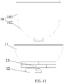
- fig. 13 is a schematic view of a partial structure of the wok device 1 in FIG. 11 .
- the wok device 1 for full-automatic cooking machines includes a wok 10, a wok heating device 11, a wok rotating device 12, a wok working position controlling device 13 and a wok moving control device 14;
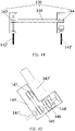
- FIG. 14 is a structural schematic view of the wok moving control device 14 of the wok device 1 in FIG. 11
- FIG. 15 is a side view of FIG. 14 .
- the wok moving control device 14 includes a main driving screw rod 141', an auxiliary driving screw rod 142', a driving motor 143', a synchronous rotating assembly 150 and two moving connecting pieces 140'.
- the two moving connecting pieces 140' are used for being connected with the two sides of the wok 10 respectively; in particular to both sides of the protective shell 16 respectively; the first end of the main driving screw rod 141' is connected with one of the moving connecting pieces 140', and the first end of the auxiliary driving screw rod 142' is connected with the other one of the moving connecting pieces 140'; the second end of the main driving screw rod 141' is connected with the second end of the auxiliary driving screw rod 142' through the synchronous rotating assembly 150; the driving motor 143' is used for driving the main driving screw rod 141' to rotate; the main driving screw rod 141' and the auxiliary driving screw rod 142' are maintained in parallel.
- the operating principle of the wok moving control device in the embodiment of the invention is as follows: the driving motor 143' drives the main driving screw rod 141' to rotate, and drives the auxiliary driving screw rod 142' to rotate through the synchronous rotating assembly 150, that is, the driving motor 143' rotates to drive the main driving screw rod 141' and the auxiliary driving screw rod 142' to rotate at the same time; the main driving screw rod 141' and the auxiliary driving screw rod 142' respectively convert rotation into linear motion to drive the left side and the right side of the wok 10 to move front and back synchronously.
- the embodiment of the present invention adopts double-side synchronous driving, avoids the distortion of the wok device caused by single-side driving, and only needs one driving motor 143', thereby having simple structure and reducing cost.
- the synchronous rotating assembly 150 includes a first synchronous wheel 144', a second synchronous wheel 145 and a first synchronous belt 146; the first synchronous wheel 144' is arranged on the main driving screw rod 141'; the second synchronous wheel 145 is arranged on the auxiliary driving screw rod 142'; the first synchronous belt 146 is connected with the first synchronous wheel 144' and the second synchronous wheel 145, so that the first synchronous wheel 144' drives the second synchronous wheel 145 to rotate when rotating.
- the rotation of the first synchronous wheel 144' is transmitted to the second synchronous wheel 145 through the first synchronous belt 146, so that the main driving screw rod 141' drives the auxiliary driving screw rod 142' to rotate.
- the synchronous rotating assembly 150 further includes a third synchronous wheel 147, a fourth synchronous wheel 148 and a second synchronous belt 149; a driving terminal of the driving motor 143' is connected with the third synchronous wheel 147; the fourth synchronous wheel 148 is arranged on the main driving screw rod 141'; the second synchronous belt 149 is connected with the third synchronous wheel 147 and the fourth synchronous wheel 148, so that the third synchronous wheel 147 drives the fourth synchronous wheel 148 to rotate when rotating.
- the main driving screw rod 141' is indirectly driven through the third synchronous wheel 147, the fourth synchronous wheel 148 and the second synchronous belt 149 instead of directly driving the main driving screw rod 141' by adopting the driving motor 143', so that the driving motor 143' can be well protected, and the service life of the driving motor 143' is prolonged.
- the wok moving control device further includes two linear sliding rails 17 which are fixed in the cooking machine and are parallel to each other; the two moving connecting pieces 140' are movably arranged on the two linear sliding rails 17 in a one-to-one correspondence mode.
- sliding blocks are arranged on the two moving connecting pieces 140' respectively, and sliding grooves matched with the corresponding linear sliding rails 17 are respectively formed in the sliding blocks.
- the two linear sliding rails 17 are installed on a supporting beam fixed to the interior of the automatic cooking machine, and therefore the whole wok device is better supported.
- the wok moving control device 14 further includes a limit switch box arranged above one of the moving connecting pieces 140', and the limit switch box includes a first limit switch arranged at the upper limit position of the wok and a second limit switch arranged at the lower limit position of the wok. Whether the wok reaches two limit positions in the linear motion direction or not can be detected through the first limit switch and the second limit switch, and when the wok reaches the two limit positions, the driving motor 143' is stopped, so that the moving mechanism is prevented from being damaged.
- the wok moving control device 14 further includes an upper sensor and a lower sensor which are arranged on one of the moving connecting pieces 140' and used for sensing whether the up-and-down driving position of the furnace body reaches the position required by the system or not.
- the upper sensor is used for controlling the driving motor to stop rotating by the system after sensing that the wok 10 reaches a wok lid closing position when moving upwards, so that the wok 10 is positioned at the position to perform a cooking operation;
- the lower sensor is used for controlling the driving motor to stop rotating by the system after sensing that the wok 10 moves downwards to reach a wok lid opening position, so that the wok 10 is positioned at the position to perform a working position changing operation.
- the difference between the second embodiment and the first embodiment lies in that the first embodiment adopts a double-motor double-side linear driving for driving wok to move linearly, the second embodiment adopts a single-motor double-side synchronous driving for driving wok to move linearly, and the second embodiment has better synchronism, simple structure and lower cost.
- the wok device for full-automatic cooking machines includes a wok, a wok heating device, a wok rotating device, a wok working position controlling device and a wok moving control device;
- the wok heating device is adapted for heating the wok;
- the wok rotating device is connected with the wok and adapted for controlling the wok to rotate around the central axis of the wok;
- the wok working position controlling device is adapted for fixing the wok on the wok moving control device and controlling the wok to turn so as to enable the wok to reach a corresponding working position for corresponding operation;
- the wok moving control device is adapted for controlling the wok working position controlling device to move linearly in the cooking machine so as to drive the wok to move linearly in the cooking machine.
- the wok device can control the wok to move on the basis of original ability to turn for changing working positions, so that the wok can be matched with other device such as a wok lid, the automation of the automatic cooking machine is further improved, and the working efficiency of the automatic cooking machine is improved.
Landscapes
- Engineering & Computer Science (AREA)
- Food Science & Technology (AREA)
- Food-Manufacturing Devices (AREA)
- Commercial Cooking Devices (AREA)
- Frying-Pans Or Fryers (AREA)
- Cookers (AREA)
- Baking, Grill, Roasting (AREA)
Description
- The present invention relates to the technical field of intelligent household electrical appliance, more particularly to a wok device for full-automatic cooking machines and a full-automatic cooking machine.
- Chinese culinary art is extensive and profound and has a variety of cooking techniques, which mainly comprise: stir frying, stewing, deep frying, boiling, steaming, pan frying, grilling, etc. The essence of various cooking techniques is to cook ever-changing dishes with various tastes and flavors by changing food match and controlling heating. Up to now, cooking process involves a lot of manual labor and relies very much on the cooker 's experience and skills.
- Some cooking machines with high automation degree also appear at present and may comprise but are not limited to a wok device, a wok lid, a feeding device, a wok washing device and the like, and the wok device can simulate the action of a cook to stir and fry. The wok lid, the feeding device, the wok washing device and other devices are arranged around different working positions of the wok device, and the wok device is matched with a corresponding device to complete a certain operation when the wok device turns to a certain working position. For example, during cooking, the wok lid needs to be matched with the wok to seal and cover the wok; or, during feeding, the outlet of the feeding device needs to be matched with the wok. The existing wok device can only rotate or turn at a fixed position of the cooking machine, so that the wok device is difficult to be automatically matched with other devices. For example, during cooking, the wok is usually closed by the wok lid with manual operation or with a wok lid controlling device only through the gravity of the wok lid, the wok lid cannot tightly close the opening of the wok, the tightness is poor, and therefore the cooking efficiency is not high.
-
US 2005/077283 A1 relates to a cooking apparatus for providing a tilting cooking surface. The cooking apparatus include a cooking surface for receiving food; a motion element for providing movement to the cooking surface; and a coupling attached to the motion element. The coupling may traverse a periphery portion of the cooking surface, maintaining the cooking surface in a tilted position and rocking the cooking surface back and forth . -
US 2016/106259 A1 relates to a programmable controlled intelligent cooking machine comprising: a wok electromagnetic heating coils, a wok rotating device and a wok working position controlling device. The electromagnetic heating coils wind around the external wall of the wok and heat the wok under the control of the electromagnetic heating controlling device; the wok rotating device is connected with the wok so as to control the wok to rotate; the wok rotating device, the wok working position controlling device, the electromagnetic heating controlling device are connected with the electrical control device and perform respective operations according to the received control commands. -
CN 201055262 Y relates to an automatic cooking robot system including a fully automated cooking subsystem. The fully automated cooking subsystem includes an automated recipe spoon assembly, a wok robotic arm cart platform assembly, an automatic feed bowl, an automatic cleaning blade, an upper horizontal moving robotic arm assembly, a lower horizontal moving vertical lift robotic arm assembly, and a cupspoon assembly that perform cooking actions by a smart fully automatic cooking digital recipe software control subsystem and a computer system control mating action. - Aspects of the invention are set out in the appended claims. In order to overcome the defects of the existing wok device, a wok device for full-automatic cooking machines according to
claim 1 and a full-automatic cooking machine according toclaim 9 are provided to control the wok to move on the basis of original wok which can be rotated for stir-frying and turned to change the working positions, so that the wok can be matched with other device such as a wok lid, the automation of the automatic cooking machine is further improved, and the working efficiency of the automatic cooking machine is improved. - Compared with the prior art, the wok device for full-automatic cooking machines and the full-automatic cooking machine having the wok device provided by the embodiments of the present invention have the beneficial effects that: the wok device for full-automatic cooking machines includes a wok, a wok heating device, a wok rotating device, a wok working position controlling device and a wok moving control device; the wok heating device is adapted for heating the wok; the wok rotating device is connected with the wok and adapted for controlling the wok to rotate around the central axis of the wok; the wok working position controlling device is adapted for fixing the wok on the wok moving control device and controlling the wok to turn so as to enable the wok to reach a corresponding working position for corresponding operation; and the wok moving control device is adapted for controlling the wok working position controlling device to move linearly in the cooking machine so as to drive the wok to move linearly in the cooking machine. By means of the wok moving control device, the wok device can control the wok to move on the basis of original ability to turn for changing working positions, so that the wok can be matched with other device such as a wok lid, the automation of the automatic cooking machine is further improved, and the working efficiency of the automatic cooking machine is improved. Preferably, when the wok is turned to a cooking working position, the wok opening of the wok faces the wok lid. a central axis of the wok coincides with a central axis of the wok lid. and the moving direction of the wok is parallel to the central axis of the wok lid. Preferably, when a cooking operation is to be performed, firstly, the wok working position controlling device controls the wok to turn to a cooking working position, so that the wok opening is opposite to the wok lid. then the wok moving control device controls the wok to move, so that the wok opening is closed by the wok lid, and then the wok rotating device controls the wok to rotate so as to perform cooking operation; after the cooking operation is finished, the wok moving control device controls the wok to move reversely, so that the wok opening is separated from the wok lid to open the wok.
- In order to more clearly illustrate the technical solution of the present invention, the accompanying drawings, which need to be used in the embodiments, are simply described below, and obviously, the drawings in the following description are merely some embodiments of the present invention, and for those of ordinary skill in the art, without the need for inventive effort, will be apparent to those of ordinary skill in the art from the following description. Other drawings may also be acquired from these drawings.
-
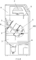
FIG. 1 is a schematic structural view of an automatic cooking machine having a wok device in a first embodiment of the present invention; -
FIG. 2 is a schematic structure view of awok device 1 for a full- automatic cooking machine in an embodiment of the present invention; -
FIG. 3 is a schematic view of a partial structure of thewok device 1 inFIG. 2 ; -
FIG. 4 is a schematic view illustrating a first state of thewok device 1 for full-automatic cooking machines at a cooking working position in an embodiment of the present invention; -
FIG. 5 is a schematic view illustrating a second state of thewok device 1 for full-automatic cooking machines at a cooking working position in an embodiment of the present invention; -
FIG. 6 is a schematic view illustrating an open state of awok 10 of the wok device for full-automatic cooking machines in an embodiment of the present invention; -
FIG. 7 is a schematic view illustrating a closed state of awok 10 of the wok device for full-automatic cooking machines in an embodiment of the present invention; -
FIG. 8 is a front view of thewok lid 8 inFIGs. 6 and7 ; -
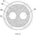
FIG. 9 is a top view of thewok lid 8 inFIGs. 6 and7 ; -
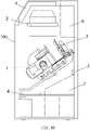
FIG. 10 is a schematic structural view of an automatic cooking machine having a wok device in a second embodiment of the present invention; -
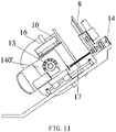
FIG. 11 is a schematic structure view of a wok device for full-automatic cooking machines in the second embodiment of the present invention; -
FIG. 12 is a side view ofFIG. 11 ; -
FIG. 13 is a schematic view of a partial structure of thewok device 1 inFIG. 11 . -
FIG. 14 is a schematic structural view of a wokmoving control device 14 of thewok device 1 inFIG. 11 ; -
FIG. 15 is a side view ofFIG. 14 . - The technical solutions of the embodiments according to the present invention are clearly and fully described as below with reference to the accompanying drawings in the embodiments of the present invention. Apparently, the embodiments to be described are merely a part rather than all of the embodiments of the present invention. All other embodiments obtained by persons with ordinary skills in the art based on the embodiments of the present invention without creative efforts shall fall within the protection scope of the present invention.
- Referring fist to
FIGs. 1 and10 ,FIG. 1 is a schematic structural view of an automatic cooking machine having a wok device in a first embodiment of the present invention, andFIG. 10 is a schematic structural view of an automatic cooking machine having a wok device in a second embodiment of the present invention. The full-automatic cooking machine may include, but is not limited to awok device 1, an automaticingredient feeding device 2, an automaticseasoning adding device 3, an automaticdish discharging device 4, an automaticwok washing device 5, a cookingfume treatment device 6, aflow guiding device 7 and amain control device 9 which are arranged in ahousing 100 of the cooking machine, and themain control device 9 is used for receiving a preset recipe program and sending a corresponding control command according to the recipe program; thewok device 1, the automaticingredient feeding device 2, the automaticseasoning adding device 3, the automaticdish discharging device 4, the automaticwok washing device 5 and the cookingfume treatment device 6 are connected to themain control device 9, and perform corresponding operation according to a received control command, thereby realizing full-automatic cooking. It should be noted that the structures of the two embodiments are similar in general structure, and both may include but are not limited to the device described above, and thus are not described separately. - In the following, with reference to
FIG. 2 , the structure of awok device 1 for full-automatic cooking machines in a first embodiment of the present invention is described in detail. Thewok device 1 for full-automatic cooking machines includes awok 10, awok heating device 11, awok rotating device 12, a wok workingposition controlling device 13 and a wokmoving control device 14; - the
wok heating device 11 is adapted for heating thewok 10; - the
wok rotating device 12 is connected with thewok 10 and adapted for controlling thewok 10 to rotate around the central axis of thewok 10; - the wok working
position controlling device 13 is adapted for fixing thewok 10 on the wokmoving control device 14 and controlling thewok 10 to turn to reach a corresponding working position for corresponding operation; - the wok
moving control device 14 is adapted for controlling the wok workingposition controlling device 13 to move linearly in the cooking machine so as to drive thewok 10 to move linearly in the cooking machine; - the
wok heating device 11, thewok rotating device 12, the wok workingposition controlling device 13 and the wokmoving control device 14 are connected with amain control device 9 of the cooking machine so as to receive a control command sent by themain control device 9 according to a preset recipe program, and respectively perform heating, rotating, turning and moving operations on thewok 10 according to the control command. - Referring to
FIG. 3 , which is a schematic view of a partial structure of thewok device 1 inFIG. 2 . The cylinder body of thewok 10 includes a hollow cylinder-shapedupper part 101 and a hemisphere-shapedlower part 102. A plurality of stirring pieces used for stir-frying food are arranged on the inner wall of thelower part 102 of thewok 10, so as to achieve stir-frying effects like tossing the wok when thewok 10 is rotated for cooking. The number of the stirring pieces arranged on the inner wall of thelower part 102 of thewok 10 may be 2, 3 or 4. Thewok 10 is a stainless iron wok suitable for electromagnetic heating with the entire inner wall of thewok 10 coated with a non-stick material layer having excellent heat resistance, so that thewok 10 has multiple functions of heating food non-stick pan, self-cleaning, easy dish discharging, easier pan washing and low-oil cooking. - The
wok heating device 11 includes an electromagnetic heating coil and an electromagnetic heating controlling device; the electromagnetic heating coil winds around the outer wall of thewok 10 and heats thewok 10 under the control of the electromagnetic heating control device. The electromagnetic heating coil is a semispherical coil and is formed by surrounding a semispherical coil framework made of a heat-resistant material with a pure copper high-frequency heating coil. The electromagnetic heating coil winds around the outer wall of thelower part 102 of thewok 10 and heats thewok 10 under the control of the electromagnetic heating control device. Due to the electromagnetic heating, a three-dimensional surround hemisphere heating temperature field which heats quickly and has high thermal efficiency is formed in thewok 10. The formed heating temperature field has a similar effect as traditional blowing-type cook-stoves heating wok, it greatly meets the requirement of heating control in Chinese culinary art and is energy-efficient. In addition, the electromagnetic heating has no time lag, so that the method of electromagnetic heating is much more sensitive than the traditional modes of open fire or resistance power generation conduction and the like for adjusting the cooking heating degree. - The
wok rotating device 12 includes a rotating shaft and a stir-frying motor, the rotating shaft is fixedly connected with thewok 10, the stir-frying motor is connected with themain control device 9 of the automatic cooking machine and drives the rotating shaft to rotate when receives rotating control commands sent by themain control device 9, thereby driving thewok 10 to rotate by 360 degrees. In particular, the stir-frying motor is fixed below the electromagnetic heating coil through awok connecting device 15, one end of the rotating shaft is fixedly connected to thelower part 102 of thewok 10, the other end of the rotating shaft is connected with the stir-frying motor, and the rotating shaft coincides with the central axis of thewok 10 and rotates under the control of the stir-frying motor, so as to drive thewok 10 to achieve various rotation motions. The stir-frying function of the stir-wok 10 in the present embodiment realizes various stir-frying effects in the way of rotation motions combination control, which is similar to a roller rotating and stirring. Various effects like saute-stirring and stir-frying can be realized by combining various rotation modes including high-speed rotation, low-speed rotation, clockwise rotation and anti-clockwise rotation. By cooperatively using stirring pieces arranged in thewok 10 and controlling the rotating angle of the wok 10 (by a wok working position controlling device 13), the stir-frying effect like tossing the pan can be realized. - In an alternative embodiment, the
wok device 1 further includes aprotective shell 16; thewok 10, thewok heating device 11 and thewok rotating device 12 are arranged in theprotective shell 16; two moving connectingpieces 142 of the wok movingcontrol device 14 are respectively connected with two sides of theprotective shell 16; the wok workingposition controlling device 13 is connected with theprotective shell 16 through the moving connectingpieces 142 so as to control thewok 10 in theprotective shell 16 to turn, and the wok workingposition controlling device 13 is driven by the wok movingcontrol device 14 to drive thewok 10 in theprotective shell 16 to move. Theprotective shell 16 can play a role in protecting thewok 10, thewok heating device 11 and thewok rotating device 12. - In an alternative embodiment, the wok working
position controlling device 13 comprises working position rotating shafts 131 and a workingposition motor 132 used for driving the working position rotating shafts 131 to rotate; the working position rotating shafts 131 are respectively connected to two opposite sides of theprotective shell 16, and one of the working position rotating shafts 131 is connected with the workingposition motor 132; the workingposition motor 132 is mounted on one of the moving connecting pieces, and the other of the working position rotating shafts 131 is connected with the other one of moving connecting pieces. Therefore, the workingposition motor 132 can drive theprotective shell 16 to turn through the working position rotating shafts131 to drive thewok 10 to turn, and the orientation of the wok opening of thewok 10 is changed, so that thewok 10 can work at different working positions. - In the embodiment of the present invention, the wok moving
control device 14 includes two sets of movingcontrol assemblies 140; each set of the movingcontrol assemblies 140 includes antelescopic rod 141, a moving connectingpiece 142 and a wok movinglinear motor 143 fixed in the cooking machine; the two moving connectingpieces 142 are respectively arranged on both sides of thewok 10, in particular on both sides of theprotective shell 16; one end of thetelescopic rod 141 is connected with a driving terminal of the corresponding wok movinglinear motor 143 in the same set of movingcontrol assemblies 140, and the other end of thetelescopic rod 141 is connected with the corresponding moving connectingpiece 142; and the twotelescopic rods 141 are arranged in parallel. - That is, the two opposite sides of the
wok 10 are each provided with one of the movingcontrol assemblies 140 used for carrying out the same-direction linear motion. The two sets of the movingcontrol assemblies 140 have the advantages of better bearing the weight of thewok 10, preventing thewok 10 from inclining to one side and improving the structural stability. Under the driving of the wok movinglinear motors 143, thetelescopic rods 141 move telescopically in a straight line to drive the wok workingposition controlling device 13, thewok 10 and other devices connected with thewok 10 to move. - Preferably, each set of the moving
control assemblies 140 further includes a movingguide rail 144 fixed inside the cooking machine. The movingguide rails 144 in the two sets of movingcontrol assemblies 140 are parallel to each other; thetelescopic rod 141 and the moving connectingpiece 142 in the same set of the movingcontrol assemblies 140 are disposed on the correspondingmovable guide rail 144, so that the wok movinglinear motors 143 drive thewok 10 to move linearly in a direction parallel to the moving guide rails 144. The movingguide rails 144 can assist the movement of thetelescopic rods 141 and prevent thetelescopic rods 141 from being affected by external force such as gravity, thereby ensuring that thewok 10 moves in a straight line. - More preferably, the wok moving
control device 14 further includes an upper sensor and a lower sensor which are arranged on one of the moving connectingpieces 140 and used for sensing whether the position of thewok 10 driven up and down reaches the position demanded by the system or not. The upper sensor is used for controlling the driving motors to stop rotating by the system after sensing that thewok 10 reaches a wok lid closing position when moving upwards, so that thewok 10 is positioned at the position to perform a cooking operation; and the lower sensor is used for controlling the driving motors to stop rotating by the system after sensing that thewok 10 moves downwards to reach a wok lid opening position, so that thewok 10 is positioned at the position to perform working position changing operation. - In the embodiment, five working positions are provided according to different mounting positions of operating devices of the full-automatic cooking machine, i.e. an ingredient feeding working position, an seasoning adding (cooking) working position, a dish discharging working position, a wok washing working position and a waste water draining working position, and when the wok working
position controlling device 13 drives thewok 10 to turn to each working position, and makes the opening of thewok 10 face towards each corresponding device so as to perform corresponding automatic cooking operations such as ingredient feeding, cooking (seasoning adding), dish discharging, wok washing, waste water draining, etc. For example, - when the wok working
position controlling device 13 receives a major ingredient feeding control command, thewok 10 is turned to an ingredient feeding working position (which is vertical position, namely, the original position), so as to make the opening of thewok 10 face towards the automaticingredient feeding device 2; - when the wok working
position controlling device 13 receives an seasoning adding command or a rotating control command, thewok 10 is turned to an seasoning adding (cooking) working position (which is preferably a position with a 45-degree angle to the original position) in a clockwise direction, so as to make the opening of thewok 10 face towards awok lid 8, and the working state of thewok device 1 is shown inFIG. 4 at the moment; then the wok movingcontrol device 14 receives a wok lid closing control command and controls thewok 10 to move towards thewok lid 8, so that the opening of thewok 10 is covered with thewok cover 8, and the working state of thewok device 1 is shown in theFIG. 5 at the moment; and then, thewok rotating device 12 controls thewok 10 to rotate to perform cooking operation; - when the wok working
position controlling device 13 receives a dish discharging control command, thewok 10 is turned to a dish discharging working position (which is preferably a position with a 135-degree angle to the original position) in a clockwise direction, so as to make the opening of thewok 10 face towards the automaticdish discharging device 4; - when the wok working
position controlling device 13 receives a wok washing control command, thewok 10 is turned to a wok washing working position (which is preferably a position with a 45-degree angle to the original position) in an anti-clockwise direction, so as to make the opening of thewok 10 face towards the automaticwok washing device 5 and when receiving a waste water draining control command after the wok washing is finished, the wok is further turn to a waste water draining working position (preferably, the inclination angle between thewok 10 and the initial state is 225-235 degrees) in an anti-clockwise direction, so as to make the opening of thewok 10 face towards theflow guiding device 7. - Therefore, the wok device for full-automatic cooking machines provided by the embodiment of the invention not only can control the
wok 10 to rotate through thewok rotating device 12 for stir-frying, and control thewok 10 to turn through the wok workingposition controlling device 13 so as to enable thewok 10 to reach a corresponding working position for corresponding operation, but also can control thewok 10 to move through the wok movingcontrol device 14 so as to enable thewok 10 to be better matched with other devices of the cooking machine, for example, the wok can be matched with thewok lid 8, and the wok can be turned to the cooking working position and moved to keep a tightly closed state with thewok lid 8 during cooking, so that the automation of the cooking machine is further improved, and the working efficiency of the cooking machine is improved. - It should be noted that, in the wok device for full-automatic cooking machines provided by the embodiment of the invention, the wok moving
control device 14 controls thewok 10 to move so as to be matched with thewok lid 8 to perform a cooking operation, but this is only one implementation manner, and the wok movingcontrol device 14 may also control thewok 10 to move so as to be matched with other device, such as the automaticingredient feeding device 2 or the automaticdish discharging device 4, to perform other operation. - Meanwhile, the wok device for full-automatic cooking machines provided by the embodiment of the invention further includes a
wok lid 8 which is fixed inside the cooking machine and matched with the opening of thewok 10. - Referring to
FIG.s 6 and7 ,FIG. 6 is a schematic view illustrating an open state of awok 10 of the wok device for full-automatic cooking machines in an embodiment of the present invention, andFIG. 7 is a schematic view illustrating a closed state of awok 10 of the wok device for full-automatic cooking machines in an embodiment of the present invention. - The moving direction of the
wok 10 is parallel to the central axis of thewok lid 8; when thewok 10 is turned to the cooking working position, the opening of thewok 10 faces thewok lid 8 and the central axis of thewok 10 coincides with the central axis of thewok lid 8. Therefore, when a cooking operation is to be performed, firstly, thewok 10 is turned to the cooking working position through the wok workingposition controlling device 13, so that the opening of thewok 10 is right opposite to thewok lid 8, and the state is shown in theFIG. 4 ; then, thewok 10 is moved through the wok movingcontrol device 14, so that the opening of thewok 10 is closed by thewok lid 8; and then, thewok 10 is controlled by thewok rotating device 12 to rotate for cooking; after the cooking operation is finished, thewok 10 is to be opened, and thewok 10 is moved through the wok movingcontrol device 14 to separate from thewok lid 8. - Referring to
FIG. 8, FIG. 8 is a front view of thewok lid 8 inFIGs.6 and7 . Thewok lid 8 includes awok lid plate 81 and a wok lid sealing container; the wok lid sealing container includes a fixingpart 82 installed on thewok lid plate 81 and a sealingstrip 83 which can be arranged on the periphery of the fixingpart 82 in a relatively rotating and sleeving mode. An area enclosed by the sealingstrip 83 is matched with the opening of thewok 10 in size and shape. Therefore, when thewok lid 8 seals the opening of thewok 10 through the sealingstrip 83 and thewok 10 rotates, the sealingstrip 83 rotates along with thewok 10, so that the resistance of thewok 10 as it rotates is reduced. - Preferably, the
wok lid plate 81 is provided with a cookingfume channel opening 84 communicated with the cookingfume treatment device 6 of the cooking machine; the fixingpart 82 is provided with a first communication opening communicated with the cookingfume channel opening 84; thewok lid plate 81 is provided with anseasoning adding opening 85 communicated with the automaticseasoning adding device 3 of the cooking machine; and the fixingpart 82 is provided with a second communication opening communicated with theseasoning adding opening 85, as shown inFIG. 9 which is a top view of thewok lid 8 inFIGs. 6 and7 . - As a modified embodiment, the
wok lid plate 81 is provided with a common channel opening; the common channel opening is communicated with the cookingfume treatment device 6 and the automaticseasoning adding device 3 of the cooking machine; and a common communication opening communicated with the common channel opening is formed in the fixingpart 82. That is, the cookingfume channel opening 84 and theseasoning adding opening 85 are achieved through the common channel opening at the same time, and seasoning adding or cooking fume extracting can be performed through the common channel opening. - Preferably, the fixing
part 82 is detachably installed on thewok lid plate 81. - Compared with the first embodiment, the second embodiment has a main difference that the structure of the wok devices are different due to the fact that the structures of the wok moving control devices are different, only the correspondingly connection parts of the wok device and of the wok moving control device are described hereinafter in an image-text mode, and the rest parts of the wok device can all adopt the means of the first embodiment, which are not described in detail in the second embodiment.
- In the following, the structure of the wok device for full-automatic cooking machines according to the second embodiment of the present invention is described in detail with reference to
FIGs. 11-13 .FIG. 11 is a schematic structure view of a wok device for full-automatic cooking machines in the second embodiment of the present invention,FIG. 12 is a side view ofFIG. 11 , andfig. 13 is a schematic view of a partial structure of thewok device 1 inFIG. 11 . Thewok device 1 for full-automatic cooking machines includes awok 10, awok heating device 11, awok rotating device 12, a wok workingposition controlling device 13 and a wok movingcontrol device 14; - the
wok heating device 11 is adapted for heating thewok 10; - the
wok rotating device 12 is connected with thewok 10 and adapted for controlling thewok 10 to rotate around the central axis of thewok 10; - the wok working
position controlling device 13 is adapted for fixing thewok 10 to the wok movingcontrol device 14 and controlling thewok 10 to turn to reach a corresponding working position for corresponding operation; - the wok moving
control device 14 is adapted for controlling the wok workingposition controlling device 13 to move linearly in the cooking machine so as to drive thewok 10 to move linearly in the cooking machine; - the
wok heating device 11, thewok rotating device 12, the wok workingposition controlling device 13 and the wok movingcontrol device 14 are connected with amain control device 9 of the cooking machine so as to receive a control command sent by themain control device 9 according to a preset recipe program, and respectively perform heating, rotating, turning and moving operations on thewok 10 according to the control command. - Referring to
FIGs. 14 and 15, FIG. 14 is a structural schematic view of the wok movingcontrol device 14 of thewok device 1 inFIG. 11 , andFIG. 15 is a side view ofFIG. 14 . - The wok moving
control device 14 includes a main driving screw rod 141', an auxiliary driving screw rod 142', a driving motor 143', a synchronousrotating assembly 150 and two moving connecting pieces 140'. The two moving connecting pieces 140' are used for being connected with the two sides of thewok 10 respectively; in particular to both sides of theprotective shell 16 respectively; the first end of the main driving screw rod 141' is connected with one of the moving connecting pieces 140', and the first end of the auxiliary driving screw rod 142' is connected with the other one of the moving connecting pieces 140'; the second end of the main driving screw rod 141' is connected with the second end of the auxiliary driving screw rod 142' through the synchronousrotating assembly 150; the driving motor 143' is used for driving the main driving screw rod 141' to rotate; the main driving screw rod 141' and the auxiliary driving screw rod 142' are maintained in parallel. - The operating principle of the wok moving control device in the embodiment of the invention is as follows: the driving motor 143' drives the main driving screw rod 141' to rotate, and drives the auxiliary driving screw rod 142' to rotate through the synchronous
rotating assembly 150, that is, the driving motor 143' rotates to drive the main driving screw rod 141' and the auxiliary driving screw rod 142' to rotate at the same time; the main driving screw rod 141' and the auxiliary driving screw rod 142' respectively convert rotation into linear motion to drive the left side and the right side of thewok 10 to move front and back synchronously. The embodiment of the present invention adopts double-side synchronous driving, avoids the distortion of the wok device caused by single-side driving, and only needs one driving motor 143', thereby having simple structure and reducing cost. - Preferably, the synchronous
rotating assembly 150 includes a first synchronous wheel 144', a secondsynchronous wheel 145 and a firstsynchronous belt 146; the first synchronous wheel 144' is arranged on the main driving screw rod 141'; the secondsynchronous wheel 145 is arranged on the auxiliary driving screw rod 142'; the firstsynchronous belt 146 is connected with the first synchronous wheel 144' and the secondsynchronous wheel 145, so that the first synchronous wheel 144' drives the secondsynchronous wheel 145 to rotate when rotating. The rotation of the first synchronous wheel 144' is transmitted to the secondsynchronous wheel 145 through the firstsynchronous belt 146, so that the main driving screw rod 141' drives the auxiliary driving screw rod 142' to rotate. - Preferably, the synchronous
rotating assembly 150 further includes a thirdsynchronous wheel 147, a fourthsynchronous wheel 148 and a secondsynchronous belt 149; a driving terminal of the driving motor 143' is connected with the thirdsynchronous wheel 147; the fourthsynchronous wheel 148 is arranged on the main driving screw rod 141'; the secondsynchronous belt 149 is connected with the thirdsynchronous wheel 147 and the fourthsynchronous wheel 148, so that the thirdsynchronous wheel 147 drives the fourthsynchronous wheel 148 to rotate when rotating. According to the embodiment of the invention, the main driving screw rod 141' is indirectly driven through the thirdsynchronous wheel 147, the fourthsynchronous wheel 148 and the secondsynchronous belt 149 instead of directly driving the main driving screw rod 141' by adopting the driving motor 143', so that the driving motor 143' can be well protected, and the service life of the driving motor 143' is prolonged. - Preferably, the wok moving control device further includes two linear sliding
rails 17 which are fixed in the cooking machine and are parallel to each other; the two moving connecting pieces 140' are movably arranged on the two linear slidingrails 17 in a one-to-one correspondence mode. Specifically, sliding blocks are arranged on the two moving connecting pieces 140' respectively, and sliding grooves matched with the corresponding linear slidingrails 17 are respectively formed in the sliding blocks. - Preferably, the two linear sliding
rails 17 are installed on a supporting beam fixed to the interior of the automatic cooking machine, and therefore the whole wok device is better supported. - Preferably, the wok moving
control device 14 further includes a limit switch box arranged above one of the moving connecting pieces 140', and the limit switch box includes a first limit switch arranged at the upper limit position of the wok and a second limit switch arranged at the lower limit position of the wok. Whether the wok reaches two limit positions in the linear motion direction or not can be detected through the first limit switch and the second limit switch, and when the wok reaches the two limit positions, the driving motor 143' is stopped, so that the moving mechanism is prevented from being damaged. - More preferably, the wok moving
control device 14 further includes an upper sensor and a lower sensor which are arranged on one of the moving connecting pieces 140' and used for sensing whether the up-and-down driving position of the furnace body reaches the position required by the system or not. The upper sensor is used for controlling the driving motor to stop rotating by the system after sensing that thewok 10 reaches a wok lid closing position when moving upwards, so that thewok 10 is positioned at the position to perform a cooking operation; the lower sensor is used for controlling the driving motor to stop rotating by the system after sensing that thewok 10 moves downwards to reach a wok lid opening position, so that thewok 10 is positioned at the position to perform a working position changing operation. - Compared with the first embodiment, the difference between the second embodiment and the first embodiment lies in that the first embodiment adopts a double-motor double-side linear driving for driving wok to move linearly, the second embodiment adopts a single-motor double-side synchronous driving for driving wok to move linearly, and the second embodiment has better synchronism, simple structure and lower cost.
- Compared with the prior art, the wok device for full-automatic cooking machines provided by the embodiments of the present invention has the beneficial effects that: the wok device for full-automatic cooking machines includes a wok, a wok heating device, a wok rotating device, a wok working position controlling device and a wok moving control device; the wok heating device is adapted for heating the wok; the wok rotating device is connected with the wok and adapted for controlling the wok to rotate around the central axis of the wok; the wok working position controlling device is adapted for fixing the wok on the wok moving control device and controlling the wok to turn so as to enable the wok to reach a corresponding working position for corresponding operation; and the wok moving control device is adapted for controlling the wok working position controlling device to move linearly in the cooking machine so as to drive the wok to move linearly in the cooking machine. By means of the wok moving control device, the wok device can control the wok to move on the basis of original ability to turn for changing working positions, so that the wok can be matched with other device such as a wok lid, the automation of the automatic cooking machine is further improved, and the working efficiency of the automatic cooking machine is improved.
Claims (10)
- A wok device (1) for full-automatic cooking machines, comprising a wok (10), a wok heating device (11), a wok rotating device (12), a wok working position controlling device (13), a wok moving control device (14), and a protective shell (16), wherein:the wok heating device (11) is adapted for heating the wok (10);the wok rotating device (12) is connected with the wok (10) and adapted for controlling the wok (10) to rotate around a central axis of the wok (10);the wok working position controlling device (13) is adapted for fixing the wok (10) on the wok moving control device (14) and controlling the wok (10) to turn to reach a corresponding working position for corresponding operation;the wok moving control device (14) is adapted for controlling the wok working position controlling device (13) to move linearly in the cooking machine so as to drive the wok (10) to move linearly in the cooking machine;the wok heating device (11), the wok rotating device (12), the wok working position controlling device (13) and the wok moving control device (14) are connected with a main control device (9) of the cooking machine so as to receive a control command sent by the main control device (9) according to a preset recipe program, and respectively perform heating, rotating, turning and moving operations on the wok (10) according to the control command;the wok (10), the wok heating device (11) and the wok rotating device (12) are arranged in the protective shell (16); andthe wok working position controlling device (13) is connected with the protective shell (16) to control the wok (10) in the protective shell (16) to turn, and the wok working position controlling device (13) is driven by the wok moving control device (14) to drive the wok (10) in the protective shell (16) to move;characterized in that:
the wok moving control device (14) comprises a main driving screw rod (141'), an auxiliary driving screw rod (142'), a driving motor (143'), a synchronous rotating assembly (150) and two moving connecting pieces (140'), wherein:the two moving connecting pieces (140') are adapted for being connected with both sides of the protective shell (16) respectively;a first end of the main driving screw rod (141') is connected with one of the two moving connecting pieces (140'), and a first end of the auxiliary driving screw rod (142') is connected with the other one of the two moving connecting pieces (140');a second end of the main driving screw rod (141') is connected with a second end of the auxiliary driving screw rod (142') through the synchronous rotating assembly (150);the driving motor (143') is adapted for driving the main driving screw rod (141') to rotate and driving the auxiliary driving screw rod (142') to rotate through the synchronous rotating assembly (150);the main driving screw rod (141') and the auxiliary driving screw rod (142') are maintained parallel to each other;the synchronous rotating assembly (150) comprises a first synchronous wheel (144'), a second synchronous wheel (145) and a first synchronous belt (146), wherein the first synchronous wheel (144') is arranged on the main driving screw rod (141'), the second synchronous wheel (145) is arranged on the auxiliary driving screw rod (142'), and the first synchronous belt (146) is connected with the first synchronous wheel (144') and the second synchronous wheel (145), so that rotation of the first synchronous wheel (144') drives the second synchronous wheel (145) to rotate. - The wok device (1) for full-automatic cooking machines according to claim 1, wherein:the synchronous rotating assembly (150) further comprises a third synchronous wheel (147), a fourth synchronous wheel (148) and a second synchronous belt (149);a driving terminal of the driving motor (143') is connected with the third synchronous wheel (147);the fourth synchronous wheel (148) is arranged on the main driving screw rod (141'); andthe second synchronous belt (149) is connected with the third synchronous wheel (147) and the fourth synchronous wheel (148), so that rotation of the third synchronous wheel (147) drives the fourth synchronous wheel (148) to rotate.
- The wok device (1) for full-automatic cooking machines according to claim 2, wherein:the wok moving control device (14) further comprises two linear sliding rails (17) which are fixed in the cooking machine and are parallel to each other; andthe two moving connecting pieces (140') are movably arranged on the two linear sliding rails (17) respectively.
- The wok device for full-automatic cooking machines according to any one of claims 1-3, wherein:the wok working position controlling device (13) comprises working position rotating shafts (131) and a working position motor (132) adapted for driving the working position rotating shafts (131) to rotate;the working position rotating shafts (131) are respectively connected to two opposite sides of the protective shell (16), and one of the working position rotating shafts (131) is connected with the working position motor (132); andthe working position motor (132) is mounted on one of the two moving connecting pieces (140'), and another one of the working position rotating shafts (131) is connected with the other one of the two moving connecting pieces (140').
- The wok device (1) for full-automatic cooking machines according to any one of claims 1-3, wherein:the wok moving control device (14) further comprises a limit switch box arranged above one of the two moving connecting pieces (140'); andthe limit switch box comprises a first limit switch arranged at an upper limit position of the wok (10) and a second limit switch arranged at a lower limit position of the wok (10).
- The wok device (1) for full-automatic cooking machines according to any one of claims 1-5 further comprising a wok lid (8) fixed in the cooking machine and matched with a wok opening of the wok (10), wherein the wok moving control device (14) drive the wok (10) to move up or down, so that the wok opening of the wok (10) is closed or opened by the wok lid (8).
- The wok device (1) for full-automatic cooking machines according to claim 6, wherein, when the wok (10) is turned to a cooking working position, the wok opening of the wok (10) faces the wok lid (8), a central axis of the wok (10) coincides with a central axis of the wok lid (8), and the moving direction of the wok (10) is parallel to the central axis of the wok lid (8).
- The wok device (1) for full-automatic cooking machines according to claim 7, wherein, when a cooking operation is to be performed, firstly, the wok working position controlling device (13) controls the wok (10) to turn to a cooking working position, so that the wok opening is opposite to the wok lid (8), then the wok moving control device (14) controls the wok (10) to move, so that the wok opening is closed by the wok lid (8), and then the wok rotating device (12) controls the wok (10) to rotate so as to perform cooking operation; after the cooking operation is finished, the wok moving control device (14) controls the wok (10) to move reversely, so that the wok opening is separated from the wok lid (8) to open the wok (10).
- A full-automatic cooking machine comprises a housing (100) and the wok device (1) for full-automatic cooking machines according to any one of claims 1-8, wherein the wok device (1) is arranged in the housing (100).
- The full-automatic cooking machine according to claim 9 further comprising an automatic ingredient feeding device (2), an automatic seasoning adding device (3), an automatic dish discharging device (4), an automatic wok washing device (5), a cooking fume treatment device (6), a flow guiding device (7) and a main control device (9) which are arranged in the housing (100), wherein:the main control device (9) is adapted for receiving a preset recipe program and sending a corresponding control command according to the recipe program; andthe wok device (1), the automatic ingredient feeding device (2), the automatic seasoning adding device (3), the automatic dish discharging device (4), the automatic wok washing device (5) and the cooking fume treatment device (6) are connected to the main control device (9), and perform corresponding operation according to a received control command, thereby realizing full-automatic cooking.
Applications Claiming Priority (2)
| Application Number | Priority Date | Filing Date | Title |
|---|---|---|---|
| CN201711070487.0A CN107736790B (en) | 2017-11-03 | 2017-11-03 | A frying pan device suitable for automatic cooking machine |
| PCT/CN2017/117454 WO2019085208A1 (en) | 2017-11-03 | 2017-12-20 | Cooking vessel device applicable to fully automated stir fry machine |
Publications (3)
| Publication Number | Publication Date |
|---|---|
| EP3689193A1 EP3689193A1 (en) | 2020-08-05 |
| EP3689193A4 EP3689193A4 (en) | 2021-06-16 |
| EP3689193B1 true EP3689193B1 (en) | 2022-06-29 |
Family
ID=61233303
Family Applications (1)
| Application Number | Title | Priority Date | Filing Date |
|---|---|---|---|
| EP17930285.6A Active EP3689193B1 (en) | 2017-11-03 | 2017-12-20 | Cooking vessel device applicable to fully automated stir fry machine |
Country Status (6)
| Country | Link |
|---|---|
| US (1) | US11622650B2 (en) |
| EP (1) | EP3689193B1 (en) |
| JP (1) | JP7153171B2 (en) |
| KR (1) | KR102408673B1 (en) |
| CN (1) | CN107736790B (en) |
| WO (1) | WO2019085208A1 (en) |
Families Citing this family (20)
| Publication number | Priority date | Publication date | Assignee | Title |
|---|---|---|---|---|
| CN107647767A (en) * | 2017-11-03 | 2018-02-02 | 深圳市创新先进科技有限公司 | Full-automatic frying machine |
| CN108567316B (en) * | 2018-05-10 | 2020-11-10 | 山东天智信息科技有限公司 | Cooking machine with scald preventing function |
| CN111214119B (en) * | 2018-12-27 | 2023-05-12 | 上海爱餐机器人(集团)有限公司 | Rotating disc assembly of pot cover device and pot cover device |
| CN112237369A (en) * | 2019-07-19 | 2021-01-19 | 深圳市德信数据科技有限公司 | Bumping device and control method thereof |
| CN112294085B (en) * | 2019-07-31 | 2024-05-07 | 昆山少亨自动化设备有限公司 | Synchronous feedback adjusting device of transmission system of food material processing device |
| CN110250897B (en) * | 2019-08-07 | 2020-11-20 | 山东大学 | A kind of instant food cooking device and using method |
| CN110547669B (en) | 2019-10-08 | 2021-06-01 | 深圳技术大学 | A chromatographic identification multifunctional cooking robot |
| TWI732430B (en) * | 2020-01-17 | 2021-07-01 | 鴻道工業有限公司 | Barreled maltose dissolving device |
| CN111700482A (en) * | 2020-06-16 | 2020-09-25 | 上海冀晟自动化成套设备有限公司 | An efficient pearl automatic cooking structure |
| US20230284838A1 (en) | 2020-07-31 | 2023-09-14 | Aitme Gmbh | Apparatus and Method for Automated Food Preparation |
| CN112586971B (en) * | 2020-12-31 | 2024-05-28 | 昆山少亨自动化设备有限公司 | Intelligent kitchen capable of automatically discharging and frying |
| CN112690647B (en) * | 2021-01-11 | 2025-03-11 | 广东万和电气有限公司 | Built-in electric pressure cooker lid opening and closing mechanism |
| JP7591817B2 (en) | 2021-03-05 | 2024-11-29 | 株式会社カジワラ | Bean processing device, bean paste manufacturing device, and bean astringency management method |
| KR102258928B1 (en) * | 2021-03-16 | 2021-06-02 | 신스타프리젠츠 주식회사 | Cooking device |
| CN113261844B (en) * | 2021-05-30 | 2022-04-08 | 中国人民解放军32181部队 | Driving device for changing motion direction |
| KR102304062B1 (en) * | 2021-07-01 | 2021-09-23 | 화신주방산업(주) | Cooking Pot with Electric Rotating Device |
| CN114532830B (en) * | 2022-01-10 | 2023-09-12 | 浙江机电职业技术学院 | Automatic cooker |
| CN114532856B (en) * | 2022-03-04 | 2024-05-03 | 南京满江红传媒科技有限公司 | Structure of double-rod top pot |
| KR102624964B1 (en) * | 2023-07-17 | 2024-01-15 | 주식회사 로보테크 | Smoke Free Rotary Soup Cooker |
| CN118266740A (en) * | 2024-03-29 | 2024-07-02 | 江苏国唯智能机器人有限公司 | Intelligent unmanned rice steaming machine rice discharging mechanism for enterprise edition |
Family Cites Families (22)
| Publication number | Priority date | Publication date | Assignee | Title |
|---|---|---|---|---|
| JPH03159621A (en) * | 1989-11-17 | 1991-07-09 | Iseki & Co Ltd | Device for moving rice cooking pot in automatic rice cooker |
| JPH1128155A (en) * | 1997-07-11 | 1999-02-02 | Fuji Seiki Co Ltd | Rice cooker, method of cooking rice, and method of mixing ingredients with rice |
| JP3852760B2 (en) * | 2002-04-09 | 2006-12-06 | 株式会社品川工業所 | Kettle overturning device |
| CN1237930C (en) * | 2003-06-06 | 2006-01-25 | 罗毅 | Automatic cooker |
| US6927366B2 (en) * | 2003-10-10 | 2005-08-09 | Rks Design, Inc. | Cooking apparatus |
| CN201055262Y (en) * | 2006-01-06 | 2008-05-07 | 李卫红 | Fully automatic cooking robot system |
| CN103126536B (en) | 2013-02-28 | 2015-07-15 | 许锦标 | Pot cover control device applicable to full-automatic cooker |
| CN103126515B (en) * | 2013-02-28 | 2016-01-20 | 许锦标 | Programmable control intelligent machine for stir-frying dishes |
| CN203168901U (en) * | 2013-02-28 | 2013-09-04 | 许锦标 | Pot cover control device applied to full automatic cooker |
| CN103110339B (en) * | 2013-02-28 | 2015-09-23 | 许锦标 | Be applicable to the wok device of Full-automatic frying machine |
| CN104783642B (en) * | 2015-04-30 | 2017-05-17 | 深圳市创新先进科技有限公司 | Wok combined device of full-automatic cooker |
| JP6750797B2 (en) * | 2016-02-18 | 2020-09-02 | マイヤー インテレクチュアル プロパティーズ リミテッド | Auxiliary button for cooking system |
| CN105832140A (en) * | 2016-05-05 | 2016-08-10 | 佛山市赛米控电子科技有限公司 | Improved automatic stir-frying machine |
| CN106175416B (en) * | 2016-09-27 | 2018-09-07 | 佛山职业技术学院 | A kind of cooking machine |
| CN206324444U (en) * | 2016-09-30 | 2017-07-14 | 上海原烹即蒸餐饮管理有限公司 | With the culinary art dinner table from lift cover body |
| CN206260717U (en) * | 2016-11-25 | 2017-06-20 | 重庆龙鼎茶业有限公司 | A kind of Flat tea frying machine |
| CN107149385A (en) * | 2017-05-20 | 2017-09-12 | 太仓市夏米粒信息技术有限公司 | A kind of novel machine for stir-frying dishes |
| CN107736792A (en) * | 2017-11-03 | 2018-02-27 | 深圳市创新先进科技有限公司 | A kind of intelligent machine for stir-frying dishes |
| CN208692910U (en) * | 2017-11-03 | 2019-04-05 | 上海爱餐机器人(集团)有限公司 | A frying pan device suitable for automatic cooking machine |
| CN107669096B (en) * | 2017-11-03 | 2021-01-08 | 上海爱餐机器人(集团)有限公司 | Frying pan movement control device and frying pan device suitable for full-automatic cooker |
| CN107744328A (en) * | 2017-11-03 | 2018-03-02 | 深圳市创新先进科技有限公司 | A kind of frying pan mobile controller and the wok device suitable for Full-automatic frying machine |
| CN107647767A (en) * | 2017-11-03 | 2018-02-02 | 深圳市创新先进科技有限公司 | Full-automatic frying machine |
-
2017
- 2017-11-03 CN CN201711070487.0A patent/CN107736790B/en active Active
- 2017-12-20 JP JP2020524289A patent/JP7153171B2/en active Active
- 2017-12-20 KR KR1020207009406A patent/KR102408673B1/en active Active
- 2017-12-20 EP EP17930285.6A patent/EP3689193B1/en active Active
- 2017-12-20 WO PCT/CN2017/117454 patent/WO2019085208A1/en not_active Ceased
-
2020
- 2020-04-30 US US16/862,584 patent/US11622650B2/en active Active
Also Published As
| Publication number | Publication date |
|---|---|
| EP3689193A4 (en) | 2021-06-16 |
| US11622650B2 (en) | 2023-04-11 |
| JP7153171B2 (en) | 2022-10-14 |
| WO2019085208A1 (en) | 2019-05-09 |
| CN107736790B (en) | 2021-03-30 |
| KR102408673B1 (en) | 2022-06-14 |
| KR20200077510A (en) | 2020-06-30 |
| US20200297158A1 (en) | 2020-09-24 |
| CN107736790A (en) | 2018-02-27 |
| JP2021501641A (en) | 2021-01-21 |
| EP3689193A1 (en) | 2020-08-05 |
Similar Documents
| Publication | Publication Date | Title |
|---|---|---|
| US11622650B2 (en) | Wok device for full-automatic cooking machines and full-automatic cooking machine | |
| CN103126514B (en) | Be applicable to the dish delivery device of Full-automatic frying machine | |
| WO2019085209A1 (en) | Cooking vessel elevation control device and cooking vessel device applicable to fully automated stir fry machine | |
| CN103126513B (en) | Wok washing device applicable to full-automatic cooker | |
| CN107713714A (en) | A kind of wok device suitable for Full-automatic frying machine | |
| CN107744328A (en) | A kind of frying pan mobile controller and the wok device suitable for Full-automatic frying machine | |
| WO2019085219A1 (en) | Intelligent stir fry machine | |
| WO2014131207A1 (en) | Wok apparatus applicable in fully automated cooking machine | |
| CN103892696A (en) | Intelligent cooking equipment | |
| CN107669096B (en) | Frying pan movement control device and frying pan device suitable for full-automatic cooker | |
| CN208692910U (en) | A frying pan device suitable for automatic cooking machine | |
| CN210204406U (en) | A frying pan mechanism and an intelligent cooking machine | |
| CN203970059U (en) | Intelligent cooking equipment | |
| CN203302845U (en) | Dish-out device applied to full-automatic cooker | |
| CN208692913U (en) | A frying pan movement control device and a frying pan device suitable for a fully automatic vegetable frying machine | |
| CN208876006U (en) | A kind of wok device suitable for Full-automatic frying machine | |
| CN203789683U (en) | Energy-saving cooking robot | |
| CN208692916U (en) | Wok lift control device and wok device suitable for automatic cooking machine | |
| CN213962936U (en) | Microwave stir-frying device and automatic cooker | |
| CN208740633U (en) | A kind of frying pan mobile controller and the wok device suitable for Full-automatic frying machine | |
| CN211722739U (en) | Cooking apparatus | |
| CN205215035U (en) | Movable support overware alive in lateral part heating hamburg | |
| CN213129115U (en) | Automatic lifting noodle cooking machine | |
| CN112535404B (en) | Tea brewing container | |
| CN105231868A (en) | Using method for lateral heating lifting bakeware |
Legal Events
| Date | Code | Title | Description |
|---|---|---|---|
| STAA | Information on the status of an ep patent application or granted ep patent |
Free format text: STATUS: THE INTERNATIONAL PUBLICATION HAS BEEN MADE |
|
| PUAI | Public reference made under article 153(3) epc to a published international application that has entered the european phase |
Free format text: ORIGINAL CODE: 0009012 |
|
| STAA | Information on the status of an ep patent application or granted ep patent |
Free format text: STATUS: REQUEST FOR EXAMINATION WAS MADE |
|
| 17P | Request for examination filed |
Effective date: 20200430 |
|
| AK | Designated contracting states |
Kind code of ref document: A1 Designated state(s): AL AT BE BG CH CY CZ DE DK EE ES FI FR GB GR HR HU IE IS IT LI LT LU LV MC MK MT NL NO PL PT RO RS SE SI SK SM TR |
|
| AX | Request for extension of the european patent |
Extension state: BA ME |
|
| DAV | Request for validation of the european patent (deleted) | ||
| DAX | Request for extension of the european patent (deleted) | ||
| A4 | Supplementary search report drawn up and despatched |
Effective date: 20210517 |
|
| RIC1 | Information provided on ipc code assigned before grant |
Ipc: A47J 27/00 20060101AFI20210510BHEP Ipc: A47J 36/00 20060101ALI20210510BHEP Ipc: A47J 36/24 20060101ALI20210510BHEP Ipc: A47J 37/10 20060101ALI20210510BHEP Ipc: A47J 44/02 20060101ALI20210510BHEP |
|
| GRAP | Despatch of communication of intention to grant a patent |
Free format text: ORIGINAL CODE: EPIDOSNIGR1 |
|
| STAA | Information on the status of an ep patent application or granted ep patent |
Free format text: STATUS: GRANT OF PATENT IS INTENDED |
|
| INTG | Intention to grant announced |
Effective date: 20220302 |
|
| GRAS | Grant fee paid |
Free format text: ORIGINAL CODE: EPIDOSNIGR3 |
|
| GRAA | (expected) grant |
Free format text: ORIGINAL CODE: 0009210 |
|
| STAA | Information on the status of an ep patent application or granted ep patent |
Free format text: STATUS: THE PATENT HAS BEEN GRANTED |
|
| AK | Designated contracting states |
Kind code of ref document: B1 Designated state(s): AL AT BE BG CH CY CZ DE DK EE ES FI FR GB GR HR HU IE IS IT LI LT LU LV MC MK MT NL NO PL PT RO RS SE SI SK SM TR |
|
| REG | Reference to a national code |
Ref country code: CH Ref legal event code: EP |
|
| REG | Reference to a national code |
Ref country code: DE Ref legal event code: R096 Ref document number: 602017059137 Country of ref document: DE |
|
| REG | Reference to a national code |
Ref country code: AT Ref legal event code: REF Ref document number: 1500712 Country of ref document: AT Kind code of ref document: T Effective date: 20220715 |
|
| REG | Reference to a national code |
Ref country code: IE Ref legal event code: FG4D |
|
| REG | Reference to a national code |
Ref country code: LT Ref legal event code: MG9D |
|
| PG25 | Lapsed in a contracting state [announced via postgrant information from national office to epo] |
Ref country code: SE Free format text: LAPSE BECAUSE OF FAILURE TO SUBMIT A TRANSLATION OF THE DESCRIPTION OR TO PAY THE FEE WITHIN THE PRESCRIBED TIME-LIMIT Effective date: 20220629 Ref country code: NO Free format text: LAPSE BECAUSE OF FAILURE TO SUBMIT A TRANSLATION OF THE DESCRIPTION OR TO PAY THE FEE WITHIN THE PRESCRIBED TIME-LIMIT Effective date: 20220929 Ref country code: LT Free format text: LAPSE BECAUSE OF FAILURE TO SUBMIT A TRANSLATION OF THE DESCRIPTION OR TO PAY THE FEE WITHIN THE PRESCRIBED TIME-LIMIT Effective date: 20220629 Ref country code: HR Free format text: LAPSE BECAUSE OF FAILURE TO SUBMIT A TRANSLATION OF THE DESCRIPTION OR TO PAY THE FEE WITHIN THE PRESCRIBED TIME-LIMIT Effective date: 20220629 Ref country code: GR Free format text: LAPSE BECAUSE OF FAILURE TO SUBMIT A TRANSLATION OF THE DESCRIPTION OR TO PAY THE FEE WITHIN THE PRESCRIBED TIME-LIMIT Effective date: 20220930 Ref country code: FI Free format text: LAPSE BECAUSE OF FAILURE TO SUBMIT A TRANSLATION OF THE DESCRIPTION OR TO PAY THE FEE WITHIN THE PRESCRIBED TIME-LIMIT Effective date: 20220629 Ref country code: BG Free format text: LAPSE BECAUSE OF FAILURE TO SUBMIT A TRANSLATION OF THE DESCRIPTION OR TO PAY THE FEE WITHIN THE PRESCRIBED TIME-LIMIT Effective date: 20220929 |
|
| REG | Reference to a national code |
Ref country code: NL Ref legal event code: MP Effective date: 20220629 |
|
| REG | Reference to a national code |
Ref country code: AT Ref legal event code: MK05 Ref document number: 1500712 Country of ref document: AT Kind code of ref document: T Effective date: 20220629 |
|
| PG25 | Lapsed in a contracting state [announced via postgrant information from national office to epo] |
Ref country code: RS Free format text: LAPSE BECAUSE OF FAILURE TO SUBMIT A TRANSLATION OF THE DESCRIPTION OR TO PAY THE FEE WITHIN THE PRESCRIBED TIME-LIMIT Effective date: 20220629 Ref country code: LV Free format text: LAPSE BECAUSE OF FAILURE TO SUBMIT A TRANSLATION OF THE DESCRIPTION OR TO PAY THE FEE WITHIN THE PRESCRIBED TIME-LIMIT Effective date: 20220629 |
|
| PG25 | Lapsed in a contracting state [announced via postgrant information from national office to epo] |
Ref country code: NL Free format text: LAPSE BECAUSE OF FAILURE TO SUBMIT A TRANSLATION OF THE DESCRIPTION OR TO PAY THE FEE WITHIN THE PRESCRIBED TIME-LIMIT Effective date: 20220629 |
|
| PG25 | Lapsed in a contracting state [announced via postgrant information from national office to epo] |
Ref country code: SM Free format text: LAPSE BECAUSE OF FAILURE TO SUBMIT A TRANSLATION OF THE DESCRIPTION OR TO PAY THE FEE WITHIN THE PRESCRIBED TIME-LIMIT Effective date: 20220629 Ref country code: SK Free format text: LAPSE BECAUSE OF FAILURE TO SUBMIT A TRANSLATION OF THE DESCRIPTION OR TO PAY THE FEE WITHIN THE PRESCRIBED TIME-LIMIT Effective date: 20220629 Ref country code: RO Free format text: LAPSE BECAUSE OF FAILURE TO SUBMIT A TRANSLATION OF THE DESCRIPTION OR TO PAY THE FEE WITHIN THE PRESCRIBED TIME-LIMIT Effective date: 20220629 Ref country code: PT Free format text: LAPSE BECAUSE OF FAILURE TO SUBMIT A TRANSLATION OF THE DESCRIPTION OR TO PAY THE FEE WITHIN THE PRESCRIBED TIME-LIMIT Effective date: 20221031 Ref country code: ES Free format text: LAPSE BECAUSE OF FAILURE TO SUBMIT A TRANSLATION OF THE DESCRIPTION OR TO PAY THE FEE WITHIN THE PRESCRIBED TIME-LIMIT Effective date: 20220629 Ref country code: EE Free format text: LAPSE BECAUSE OF FAILURE TO SUBMIT A TRANSLATION OF THE DESCRIPTION OR TO PAY THE FEE WITHIN THE PRESCRIBED TIME-LIMIT Effective date: 20220629 Ref country code: AT Free format text: LAPSE BECAUSE OF FAILURE TO SUBMIT A TRANSLATION OF THE DESCRIPTION OR TO PAY THE FEE WITHIN THE PRESCRIBED TIME-LIMIT Effective date: 20220629 |
|
| PG25 | Lapsed in a contracting state [announced via postgrant information from national office to epo] |
Ref country code: PL Free format text: LAPSE BECAUSE OF FAILURE TO SUBMIT A TRANSLATION OF THE DESCRIPTION OR TO PAY THE FEE WITHIN THE PRESCRIBED TIME-LIMIT Effective date: 20220629 Ref country code: IS Free format text: LAPSE BECAUSE OF FAILURE TO SUBMIT A TRANSLATION OF THE DESCRIPTION OR TO PAY THE FEE WITHIN THE PRESCRIBED TIME-LIMIT Effective date: 20221029 |
|
| REG | Reference to a national code |
Ref country code: DE Ref legal event code: R097 Ref document number: 602017059137 Country of ref document: DE |
|
| PG25 | Lapsed in a contracting state [announced via postgrant information from national office to epo] |
Ref country code: AL Free format text: LAPSE BECAUSE OF FAILURE TO SUBMIT A TRANSLATION OF THE DESCRIPTION OR TO PAY THE FEE WITHIN THE PRESCRIBED TIME-LIMIT Effective date: 20220629 |
|
| PG25 | Lapsed in a contracting state [announced via postgrant information from national office to epo] |
Ref country code: DK Free format text: LAPSE BECAUSE OF FAILURE TO SUBMIT A TRANSLATION OF THE DESCRIPTION OR TO PAY THE FEE WITHIN THE PRESCRIBED TIME-LIMIT Effective date: 20220629 Ref country code: CZ Free format text: LAPSE BECAUSE OF FAILURE TO SUBMIT A TRANSLATION OF THE DESCRIPTION OR TO PAY THE FEE WITHIN THE PRESCRIBED TIME-LIMIT Effective date: 20220629 |
|
| PLBE | No opposition filed within time limit |
Free format text: ORIGINAL CODE: 0009261 |
|
| STAA | Information on the status of an ep patent application or granted ep patent |
Free format text: STATUS: NO OPPOSITION FILED WITHIN TIME LIMIT |
|
| 26N | No opposition filed |
Effective date: 20230330 |
|
| REG | Reference to a national code |
Ref country code: CH Ref legal event code: PL |
|
| REG | Reference to a national code |
Ref country code: BE Ref legal event code: MM Effective date: 20221231 |
|
| PG25 | Lapsed in a contracting state [announced via postgrant information from national office to epo] |
Ref country code: SI Free format text: LAPSE BECAUSE OF FAILURE TO SUBMIT A TRANSLATION OF THE DESCRIPTION OR TO PAY THE FEE WITHIN THE PRESCRIBED TIME-LIMIT Effective date: 20220629 Ref country code: LU Free format text: LAPSE BECAUSE OF NON-PAYMENT OF DUE FEES Effective date: 20221220 |
|
| PG25 | Lapsed in a contracting state [announced via postgrant information from national office to epo] |
Ref country code: LI Free format text: LAPSE BECAUSE OF NON-PAYMENT OF DUE FEES Effective date: 20221231 Ref country code: IE Free format text: LAPSE BECAUSE OF NON-PAYMENT OF DUE FEES Effective date: 20221220 Ref country code: CH Free format text: LAPSE BECAUSE OF NON-PAYMENT OF DUE FEES Effective date: 20221231 |
|
| PG25 | Lapsed in a contracting state [announced via postgrant information from national office to epo] |
Ref country code: BE Free format text: LAPSE BECAUSE OF NON-PAYMENT OF DUE FEES Effective date: 20221231 |
|
| PG25 | Lapsed in a contracting state [announced via postgrant information from national office to epo] |
Ref country code: IT Free format text: LAPSE BECAUSE OF FAILURE TO SUBMIT A TRANSLATION OF THE DESCRIPTION OR TO PAY THE FEE WITHIN THE PRESCRIBED TIME-LIMIT Effective date: 20220629 |
|
| PG25 | Lapsed in a contracting state [announced via postgrant information from national office to epo] |
Ref country code: HU Free format text: LAPSE BECAUSE OF FAILURE TO SUBMIT A TRANSLATION OF THE DESCRIPTION OR TO PAY THE FEE WITHIN THE PRESCRIBED TIME-LIMIT; INVALID AB INITIO Effective date: 20171220 |
|
| PG25 | Lapsed in a contracting state [announced via postgrant information from national office to epo] |
Ref country code: CY Free format text: LAPSE BECAUSE OF FAILURE TO SUBMIT A TRANSLATION OF THE DESCRIPTION OR TO PAY THE FEE WITHIN THE PRESCRIBED TIME-LIMIT Effective date: 20220629 |
|
| PG25 | Lapsed in a contracting state [announced via postgrant information from national office to epo] |
Ref country code: MK Free format text: LAPSE BECAUSE OF FAILURE TO SUBMIT A TRANSLATION OF THE DESCRIPTION OR TO PAY THE FEE WITHIN THE PRESCRIBED TIME-LIMIT Effective date: 20220629 |
|
| PG25 | Lapsed in a contracting state [announced via postgrant information from national office to epo] |
Ref country code: MC Free format text: LAPSE BECAUSE OF FAILURE TO SUBMIT A TRANSLATION OF THE DESCRIPTION OR TO PAY THE FEE WITHIN THE PRESCRIBED TIME-LIMIT Effective date: 20220629 |
|
| PG25 | Lapsed in a contracting state [announced via postgrant information from national office to epo] |
Ref country code: MC Free format text: LAPSE BECAUSE OF FAILURE TO SUBMIT A TRANSLATION OF THE DESCRIPTION OR TO PAY THE FEE WITHIN THE PRESCRIBED TIME-LIMIT Effective date: 20220629 |
|
| PG25 | Lapsed in a contracting state [announced via postgrant information from national office to epo] |
Ref country code: MT Free format text: LAPSE BECAUSE OF FAILURE TO SUBMIT A TRANSLATION OF THE DESCRIPTION OR TO PAY THE FEE WITHIN THE PRESCRIBED TIME-LIMIT Effective date: 20220629 |
|
| PG25 | Lapsed in a contracting state [announced via postgrant information from national office to epo] |
Ref country code: BG Free format text: LAPSE BECAUSE OF FAILURE TO SUBMIT A TRANSLATION OF THE DESCRIPTION OR TO PAY THE FEE WITHIN THE PRESCRIBED TIME-LIMIT Effective date: 20220629 |
|
| PG25 | Lapsed in a contracting state [announced via postgrant information from national office to epo] |
Ref country code: BG Free format text: LAPSE BECAUSE OF FAILURE TO SUBMIT A TRANSLATION OF THE DESCRIPTION OR TO PAY THE FEE WITHIN THE PRESCRIBED TIME-LIMIT Effective date: 20220629 |
|
| PG25 | Lapsed in a contracting state [announced via postgrant information from national office to epo] |
Ref country code: TR Free format text: LAPSE BECAUSE OF FAILURE TO SUBMIT A TRANSLATION OF THE DESCRIPTION OR TO PAY THE FEE WITHIN THE PRESCRIBED TIME-LIMIT Effective date: 20220629 |
|
| PGFP | Annual fee paid to national office [announced via postgrant information from national office to epo] |
Ref country code: DE Payment date: 20251028 Year of fee payment: 9 |
|
| PGFP | Annual fee paid to national office [announced via postgrant information from national office to epo] |
Ref country code: GB Payment date: 20251027 Year of fee payment: 9 |
|
| PGFP | Annual fee paid to national office [announced via postgrant information from national office to epo] |
Ref country code: FR Payment date: 20251027 Year of fee payment: 9 |