EP3686068B1 - Vehicle sensor system, vehicle provided with said vehicle sensor system - Google Patents
Vehicle sensor system, vehicle provided with said vehicle sensor system Download PDFInfo
- Publication number
- EP3686068B1 EP3686068B1 EP18859749.6A EP18859749A EP3686068B1 EP 3686068 B1 EP3686068 B1 EP 3686068B1 EP 18859749 A EP18859749 A EP 18859749A EP 3686068 B1 EP3686068 B1 EP 3686068B1
- Authority
- EP
- European Patent Office
- Prior art keywords
- vehicle
- nozzle
- lidar
- cleaning medium
- sensor system
- Prior art date
- Legal status (The legal status is an assumption and is not a legal conclusion. Google has not performed a legal analysis and makes no representation as to the accuracy of the status listed.)
- Active
Links
- 238000004140 cleaning Methods 0.000 claims description 124
- 239000007921 spray Substances 0.000 claims description 28
- 238000005507 spraying Methods 0.000 description 16
- 238000001514 detection method Methods 0.000 description 9
- XLYOFNOQVPJJNP-UHFFFAOYSA-N water Substances O XLYOFNOQVPJJNP-UHFFFAOYSA-N 0.000 description 7
- 230000001154 acute effect Effects 0.000 description 6
- 238000004891 communication Methods 0.000 description 5
- 239000000428 dust Substances 0.000 description 5
- 238000003780 insertion Methods 0.000 description 5
- 230000037431 insertion Effects 0.000 description 5
- 238000010586 diagram Methods 0.000 description 4
- 230000007257 malfunction Effects 0.000 description 4
- 230000015654 memory Effects 0.000 description 3
- 238000006073 displacement reaction Methods 0.000 description 2
- 230000000694 effects Effects 0.000 description 2
- 238000003384 imaging method Methods 0.000 description 2
- 230000001133 acceleration Effects 0.000 description 1
- 238000013528 artificial neural network Methods 0.000 description 1
- 230000000295 complement effect Effects 0.000 description 1
- 238000013135 deep learning Methods 0.000 description 1
- 230000006870 function Effects 0.000 description 1
- 239000007788 liquid Substances 0.000 description 1
- 238000010801 machine learning Methods 0.000 description 1
- 239000003550 marker Substances 0.000 description 1
- 239000000463 material Substances 0.000 description 1
- 230000000149 penetrating effect Effects 0.000 description 1
- 230000035945 sensitivity Effects 0.000 description 1
Images


Classifications
-
- B—PERFORMING OPERATIONS; TRANSPORTING
- B60—VEHICLES IN GENERAL
- B60S—SERVICING, CLEANING, REPAIRING, SUPPORTING, LIFTING, OR MANOEUVRING OF VEHICLES, NOT OTHERWISE PROVIDED FOR
- B60S1/00—Cleaning of vehicles
- B60S1/02—Cleaning windscreens, windows or optical devices
- B60S1/46—Cleaning windscreens, windows or optical devices using liquid; Windscreen washers
- B60S1/48—Liquid supply therefor
- B60S1/52—Arrangement of nozzles; Liquid spreading means
-
- B—PERFORMING OPERATIONS; TRANSPORTING
- B60—VEHICLES IN GENERAL
- B60S—SERVICING, CLEANING, REPAIRING, SUPPORTING, LIFTING, OR MANOEUVRING OF VEHICLES, NOT OTHERWISE PROVIDED FOR
- B60S1/00—Cleaning of vehicles
- B60S1/02—Cleaning windscreens, windows or optical devices
- B60S1/56—Cleaning windscreens, windows or optical devices specially adapted for cleaning other parts or devices than front windows or windscreens
-
- B—PERFORMING OPERATIONS; TRANSPORTING
- B60—VEHICLES IN GENERAL
- B60S—SERVICING, CLEANING, REPAIRING, SUPPORTING, LIFTING, OR MANOEUVRING OF VEHICLES, NOT OTHERWISE PROVIDED FOR
- B60S1/00—Cleaning of vehicles
- B60S1/62—Other vehicle fittings for cleaning
-
- B—PERFORMING OPERATIONS; TRANSPORTING
- B60—VEHICLES IN GENERAL
- B60R—VEHICLES, VEHICLE FITTINGS, OR VEHICLE PARTS, NOT OTHERWISE PROVIDED FOR
- B60R11/00—Arrangements for holding or mounting articles, not otherwise provided for
-
- G—PHYSICS
- G01—MEASURING; TESTING
- G01S—RADIO DIRECTION-FINDING; RADIO NAVIGATION; DETERMINING DISTANCE OR VELOCITY BY USE OF RADIO WAVES; LOCATING OR PRESENCE-DETECTING BY USE OF THE REFLECTION OR RERADIATION OF RADIO WAVES; ANALOGOUS ARRANGEMENTS USING OTHER WAVES
- G01S7/00—Details of systems according to groups G01S13/00, G01S15/00, G01S17/00
- G01S7/48—Details of systems according to groups G01S13/00, G01S15/00, G01S17/00 of systems according to group G01S17/00
- G01S7/497—Means for monitoring or calibrating
- G01S2007/4975—Means for monitoring or calibrating of sensor obstruction by, e.g. dirt- or ice-coating, e.g. by reflection measurement on front-screen
- G01S2007/4977—Means for monitoring or calibrating of sensor obstruction by, e.g. dirt- or ice-coating, e.g. by reflection measurement on front-screen including means to prevent or remove the obstruction
Definitions
- the present invention relates to a vehicle sensor system and a vehicle with the vehicle sensor system.
- a vehicle headlamp cleaner is disclosed in PTL I and the like.
- JP-A-2016-187990 JP-A-2007-24525 shows the preamble of claim 1.
- An object of the present invention is to provide a vehicle sensor system capable of efficiently spraying a cleaning medium to an on-board sensor arranged on a vehicle. and a vehicle with the vehicle sensor system.
- an object of the present invention is to provide a vehicle sensor system in which when spraying a cleaning medium to an on-board sensor for cleaning, there is no concern that a design component of a vehicle will be smudged due to the cleaning medium, and false detection of the on-board sensor due to staying of the cleaning medium can be prevented. and a vehicle with the vehicle sensor system.
- an object of the present invention is to provide a vehicle capable of easily laying out a cleaner nozzle for a LiDAR, efficiently cleaning the LiDAR and preventing malfunction of a cleaner.
- an object of the present invention is to provide a vehicle capable of efficiently spraying a cleaning medium to a LiDAR arranged on a vehicle side part.
- a vehicle sensor system of the present invention includes: an aiming mechanism, an on-board sensor that can be attached to a vehicle via the aiming mechanism, the aiming mechanism being a mechanism capable of adjusting an attaching angle of the on-board sensor to the vehicle and
- the nozzle may be attached to a support component attached to the aiming mechanism.
- the support component for the nozzle is preferably attached to the aiming mechanism, for example.
- the nozzle may be attached to a support component attached to a main body of the on-board sensor.
- the support component for the nozzle is preferably attached to the main body of the on-board sensor, for example.
- the cleaner may further include a check valve, and the check valve may be attached to the support component.
- the check valve is preferably attached.
- a component configured to restrain a piping for supplying the cleaning medium from a main body of the cleaner to the nozzle may be attached to the support component.
- the support component and the nozzle may be integrally configured.
- a vehicle of the present invention includes the above-described vehicle sensor system.
- An unclaimed vehicle sensor system includes:
- the discharge hole for escaping the cleaning medium since the discharge hole for escaping the cleaning medium is provided, there is no concern that a design component will be smudged due to the cleaning medium. Also, since the cleaning target surface is provided in the concave part of the design component, the cleaning medium is likely to stand in the concave part, which may in turn cause false detection of the on-board sensor, and the like. However, the cleaning medium is escaped from the discharge hole, so that the false detection can be prevented.
- the nozzle may be attached to the design component.
- the design component may be attached to a vehicle body of the vehicle.
- the cleaning medium sprayed from the nozzle is discharged from the discharge hole of the design component, it is possible to clean the on-board sensor without smudging the design component and the vehicle body having the design component attached thereto.
- the discharge hole may be formed as a gap between the design component and the vehicle body.
- the discharge hole may be provided on an opposite side to the nozzle with respect to the cleaning target surface.
- a vehicle of the present invention includes the above-described vehicle sensor system.
- the vehicle including the vehicle sensor system in which when spraying the cleaning medium toward the on-board sensor for cleaning, there is no concern that the design component of the vehicle will be smudged due to the cleaning medium, and the false detection of the on-board sensor due to staying of the cleaning medium can be prevented.
- An unclaimed vehicle includes:
- the nozzle of the cleaner is provided above the LiDAR, it is possible to prevent malfunction of the cleaner due to clogging of the nozzle, and the like, and to easily lay out the nozzle. Also, the cleaning medium is sprayed at an angle toward the cleaning target surface from the nozzle protruding further outward than the cleaning target surface of the LiDAR, so that it is possible to efficiently clean the cleaning target surface of the LiDAR.
- an incidence angle of the cleaning medium sprayed from the nozzle onto the cleaning target surface may be equal to or smaller than 45°.
- the incidence angle is preferably set within the range.
- the incidence angle may be 5° or greater and 30° or smaller.
- the incidence angle is more preferably set within the range.
- the cleaning target surface may be arranged further inside of the vehicle than an exterior surface of the vehicle.
- the nozzle configured as described above is more preferably used.
- the LiDAR may be arranged in a position lower than a top surface of a tire mounted to the vehicle.
- the nozzle configured as described above is preferably used.
- An unclaimed vechicle includes:
- the LiDAR may be arranged in at least one of a position lower than a top surface of a front wheel mounted to the vehicle and a further rear position of the vehicle than a central part of the front wheel.
- the nozzle configured as described above is preferably used.
- the nozzle may be integrated with a fender mole or an emblem of the vehicle.
- a distance between a side turn signal lamp attached to the vehicle and the nozzle may be shorter than a distance between a front wheel of the vehicle and the nozzle.
- the nozzle is spaced from the front wheel as much as possible, so that it is possible to prevent the nozzle clogging. Also, the nozzle is arranged close to the side turn signal lamp (STSL), so that it is possible to reduce an influence on light emitted from the STSL.
- STSL side turn signal lamp
- the vehicle sensor system and the vehicle with the vehicle sensor system of the present invention it is possible to efficiently spray the cleaning medium toward the on-board sensor arranged on the vehicle.
- the vehicle it is possible to easily lay out the cleaner nozzle with respect to the LiDAR, to efficiently clean the LiDAR. and to prevent malfunction of the cleaner.
- the vehicle it is possible to efficiently spray the cleaning medium toward the LiDAR arranged on the vehicle side part.
- the directions are relative directions set relative to a vehicle 1 shown in FIG. 1 .
- the "front and rear direction” is a direction including a “forward direction” and a “rearward direction”.
- the "right and left direction” is a direction including a “leftward direction” and a “rightward direction”.
- the "upper and lower direction” is a direction including an "upward direction” and a “downward direction”.
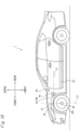
- FIG. 1 is a plan view of a vehicle 1 to which a vehicle sensor system 100 (hereinbelow, referred to as "sensor system 100") in accordance with the present embodiment is mounted.
- vehicle 1 is an automobile capable of traveling in an automatic driving mode in which traveling of the vehicle is automatically controlled.
- vehicle 1 includes the sensor system 100 for cleaning a cleaning target object (for example, an on-board sensor) provided outside of a vehicle interior.
- a cleaning target object for example, an on-board sensor
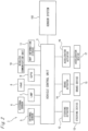
- FIG. 2 is a block diagram of the vehicle system 2.
- the vehicle system 2 includes a vehicle control unit 3 configured to control traveling of the vehicle 1.
- the vehicle control unit 3 is connected to an internal sensor 5, an external sensor 6 (an example of the on-board sensor), a lamp 7, an HMI 8 (Human Machine Interface), a GPS 9 (Global Positioning System), a wireless communication unit 10, and a map information storage 11.
- the vehicle control unit 3 is connected to a steering actuator 12, a steering device 13, a brake actuator 14, a brake device 15, an accelerator actuator 16, and an accelerator device 17.
- the vehicle control unit 3 is connected to the sensor system 100.
- the vehicle control unit 3 is configured to control traveling of the vehicle 1.
- the vehicle control unit 3 is configured by, for example, at least one electronic control unit (ECU).
- the electronic control unit includes at least one microcontroller having one or more processors and one or more memories, and an electronic circuit having an active element such as a transistor and a passive element.
- the processor is a CPU (Central Processing Unit), an MPU (Micro Processing Unit), a GPU (Graphics Processing Unit) and/or a TPU (Tensor Processing Unit), for example.
- the CPU may be configured by a plurality of CPU cores.
- the CPU may be configured by a plurality of GPU cores.
- the memory includes a ROM (Read Only Memory) and a RAM (Random Access Memory). In the ROM.
- a vehicle control program may be stored.
- the vehicle control program may include an artificial intelligence (AI) program for automatic driving.
- AI artificial intelligence
- the AI program is a program established by a supervised or unsupervised machine learning using a neural network such as deep learning.
- the RAM In the RAM. the vehicle control program, vehicle control data and/or surrounding environment information indicative of a surrounding environment of the vehicle may be temporarily stored.
- the processor may be configured to develop, on the RAM. a program designated from the vehicle control program stored in a storage device or the ROM and to execute a variety of processing in cooperation with the RAM.
- the electronic control unit may be configured by an integrated circuit (hardware resource) such as an ASIC (Application Specific Integrated Circuit), an FPGA (Field-Programmable Gate Array) and the like. Also, the electronic control unit may be configured by a combination of at least one microcontroller and an integrated circuit.
- an integrated circuit hardware resource
- ASIC Application Specific Integrated Circuit
- FPGA Field-Programmable Gate Array
- the internal sensor 5 is a sensor capable of acquiring information of a host vehicle.
- the internal sensor 5 is at least one of an acceleration sensor, a speed sensor, a wheel speed sensor, a gyro sensor, and the like, for example.
- the internal sensor 5 is configured to acquire information of the host vehicle including a traveling state of the vehicle 1, and to output the acquired information to the vehicle control unit 3.
- the internal sensor 5 may further include a seating sensor configured to detect whether a driver is sitting on a driver seat, a face direction sensor configured to detect a direction of a driver's face, and the like.
- the internal sensor 5 may include an external weather sensor configured to detect an external weather condition, an illuminance sensor configured to detect an illuminance of the surrounding environment around the vehicle 1, a passenger detection sensor configured to detect whether there is a passenger in a vehicle, and the like.
- the external sensor 6 is a sensor capable of acquiring external information of the host vehicle.
- the external sensor 6 is at least one of a LiDAR, a camera, a radar and the like, for example.
- the external sensor 6 is configured to acquire external information of the host vehicle including surrounding environments (other vehicles, pedestrians, road shapes, traffic signs, obstacles, and the like) of the vehicle 1 and to output the acquired information to the vehicle control unit 3.
- the LiDAR is an abbreviation of Light Detection and Ranging or Laser Imaging Detection and Ranging.
- the LiDAR is a sensor configured to emit non-visible light from a light receiving/emitting surface toward the front thereof, and to acquire information such as a distance to an object, a shape of an object, a material of an object, a color of an object and the like, based on emitted light and return light.
- the camera is, for example, a camera including an imaging device such as a CCD (Charge-Coupled Device) and a CMOS (complementary MOS).
- the camera is a camera configured to detect visible light or a camera configured to detect infrared light.
- the radar is a millimeter wave radar, a microwave radar, a laser radar, or the like.
- the lamp 7 is at least one of a headlamp or a position lamp provided at a front part of the vehicle 1, a rear combination lamp provided at a rear part of the vehicle 1, a turn signal lamp provided at the front part or side part of the vehicle, diverse types of lamps for notifying situations of the host vehicle to a passenger and a driver of other vehicle, and the like.
- the HMI 8 includes an input unit configured to receive an input operation from a driver and an output unit configured to output traveling information and the like to the driver.
- the input unit includes a steering wheel, an accelerator pedal, a brake pedal, a driving mode changeover switch for switching a driving mode of the vehicle I. and the like.
- the output unit is a display configured to display diverse traveling information.
- the GPS 9 is configured to acquire current position information of the vehicle 1 and to output the acquired current position information to the vehicle control unit 3.
- the wireless communication unit 10 is configured to receive traveling information of other vehicles around the vehicle 1 from the other vehicles and to transmit the traveling information of the vehicle 1 to the other vehicles (inter-vehicle communication). Also, the wireless communication unit 10 is configured to receive infrastructure information from infrastructure equipment such as a traffic light, a marker lamp and the like and to transmit the vehicle traveling information of the vehicle 1 to the infrastructure equipment (road-to-vehicle communication).
- the map information storage 11 is an external storage device such as a hard disk drive in which map information is stored, and is configured to output the map information to the vehicle control unit 3.
- the steering actuator 12 is configured to control the steering device 13, based on a steering control signal transmitted from the vehicle control unit 3.
- the brake actuator 14 is configured to control the brake device 15, based on a brake control signal transmitted from the vehicle control unit 3.
- the accelerator actuator 16 is configured to control the accelerator device 17, based on an accelerator control signal transmitted from the vehicle control unit 3.
- the vehicle 1 can drive while switching an automatic driving mode and a manual driving mode in which traveling of a vehicle is controlled by a driver's manual operation.
- the automatic driving mode includes a full-automatic driving mode, an advanced driving support mode, and a driving support mode.
- the vehicle system 2 In the full-automatic driving mode, the vehicle system 2 is configured to automatically perform all traveling controls of the steering control, the brake control and the accelerator control, and the driver is not in a state where it is possible to drive the vehicle 1.
- the vehicle system 2 is configured to automatically perform all the traveling controls of the steering control, the brake control and the accelerator control, and the driver does not drive the vehicle 1 although the driver is in a state where it is possible to drive the vehicle 1.
- the vehicle system 2 In the driving support mode, the vehicle system 2 is configured to automatically perform a part of the traveling controls of the steering control, the brake control and the accelerator control, and the driver drives the vehicle 1 under driving support of the vehicle system 2.
- the vehicle system 2 In the manual driving mode, the vehicle system 2 is configured not to automatically perform the traveling controls, and the driver drives the vehicle 1 without the driving support of the vehicle system 2.
- the driving mode of the vehicle I can be switched by the driver operating a driving mode changeover switch.
- the vehicle control unit 3 is configured to switch the driving mode of the vehicle 1 among the four driving modes (the full-automatic driving mode, the advanced driving support mode, the driving support mode, and the manual driving mode) in accordance with the operation on the driving mode changeover switch.
- the driving mode of the vehicle 1 may be automatically switched, based on information relating to a travel-allowed section where traveling of an automatic driving vehicle is allowed or a travel-prohibited section where the traveling of the automatic driving vehicle is prohibited or information relating to the external weather condition.
- the vehicle control unit 3 is configured to switch the driving mode of the vehicle 1, based on the acquired information.
- the driving mode of the vehicle 1 may be automatically switched by using a seating sensor, a face direction sensor, or the like.
- the vehicle control unit 3 is configured to switch the driving mode of the vehicle 1, based on an output signal from the seating sensor or the face direction sensor.
- the vehicle control unit 3 When the vehicle 1 travels in the automatic driving mode, the vehicle control unit 3 automatically generates at least one of the steering control signal, the accelerator control signal and the brake control signal, based on the traveling state information, the surrounding environment information, the current position information, the map information and the like.
- the vehicle control unit 3 When the vehicle 1 travels in the manual driving mode, the vehicle control unit 3 generates the steering control signal, the accelerator control signal and the brake control signal, in accordance with a driver's manual operation on the accelerator pedal, the brake pedal and the steering wheel. In this way, in the automatic driving mode, the traveling of the vehicle 1 is automatically controlled by the vehicle system 2, and in the manual driving mode, the traveling of the vehicle 1 is controlled by the driver.
- the sensor system 100 mounted to the vehicle 1 includes a front LiDAR 6f, a rear LiDAR 6b, a left LiDAR 6l. and a right LiDAR 6r, as the external sensor 6 (an example of the cleaning target object).
- the front LiDAR 6f is configured to acquire information about the front of the vehicle 1.
- the rear LiDAR 6b is configured to acquire information about the rear of the vehicle 1.
- the left LiDAR 6l is configured to acquire information about the left of the vehicle 1.
- the right LiDAR 6r is configured to acquire information about the right of the vehicle 1.
- the front LiDAR 6f is provided on a front part of the vehicle 1
- the rear LiDAR 6b is provided on a rear part of the vehicle I
- the left LiDAR 6l is provided on a left side part of the vehicle 1.
- the right LiDAR 6r is provided on a right side part of the vehicle 1.
- the present invention is not limited to the example.
- the front LiDAR, the rear LiDAR. the left LiDAR and the right LiDAR may be integrally arranged on a ceiling part of the vehicle 1.
- the sensor system 100 includes a left headlamp 7l provided on a left part of the front part of the vehicle 1 and a right headlamp 7r provided on a right part of the front part, as the lamp 7 (an example of the cleaning target object).
- the sensor system 100 includes a front window 1f and a rear window 1b, as a window shield (an example of the cleaning target object).
- the sensor system 100 includes nozzles 101 to 108 configured to spray a cleaning medium toward the cleaning target object.
- a front window washer nozzle (hereinbelow, referred to as 'front WW nozzle') 101 is configured to spray the cleaning medium toward the front window 1f.
- a rear window washer nozzle (hereinbelow, referred to as 'rear WW nozzle') 102 is configured to spray the cleaning medium toward the rear window 1b.
- a front LiDAR cleaner nozzle hereinbelow, referred to as 'front LC nozzle"
- 103 is configured to spray the cleaning medium toward the front LiDAR 6f.
- a rear LiDAR cleaner nozzle (hereinbelow, referred to as 'rear LC nozzle') 104 is configured to spray the cleaning medium toward the rear LiDAR 6b.
- a right LiDAR cleaner nozzle (hereinbelow, referred to as 'right LC nozzle') 105 is configured to spray the cleaning medium toward the right LiDAR 6r.
- a left LiDAR cleaner nozzle (hereinbelow, referred to as 'left LC nozzle') 106 is configured to spray the cleaning medium toward the left LiDAR 6l.
- a right headlamp cleaner nozzle (hereinbelow, referred to as 'right HC nozzle') 107 is configured to spray the cleaning medium toward the right headlamp 7r.
- a left headlamp cleaner nozzle (hereinbelow, referred to as 'left HC nozzle') 108 is configured to spray the cleaning medium toward the left headlamp 71.
- FIG. 3 is a block diagram of the sensor system 100.
- the sensor system 100 includes a tank I 11. a pump 112, an operation unit 115, and a control unit 116, in addition to the nozzles 101 to 108.
- the sensor system 100 is configured to spray the cleaning medium stored in the tank 111 from each of the nozzles 101 to 108 toward the cleaning target object, thereby removing foreign matters such as water droplets, mud, grit and dust, and the like attached on the cleaning target object.
- the nozzles 101 to 108 are connected to the tank 111 via the pump 112.
- the pump 112 is configured to transport the cleaning medium stored in the tank 111 to each of the nozzles 101 to 108.
- Each of the nozzles 101 to 108 is provided with an actuator configured to open the nozzle for spraying the cleaning medium toward the cleaning target object.
- the operation unit 115 is a device that can be operated by the driver of the vehicle 1, and is configured by a switch and the like provided in the vehicle interior, for example.
- the operation unit 115 is configured to output an operation signal, in correspondence to a driver's operation.
- the operation signal output from the operation unit 115 is input to the control unit 116.
- Each actuator of the nozzles 101 to 108, the pump 112, the operation unit 115 and the vehicle control unit 3 are electrically connected to the control unit 116.
- the control unit 116 is configured to control an operation of the pump 112 and an operation of each actuator of the nozzles 101 to 108, based on signals input from the operation unit 115 and the vehicle control unit 3. For example, when a signal for cleaning the front LiDAR 6f is input to the control unit 116. the control unit 116 actuates the pump 112 to transport the cleaning medium from the tank 111 to the front LC nozzle 103, and actuates the actuator of the front LC nozzle 103 to spray the cleaning medium from the front LC nozzle 103.
- the nozzles 101 to 108 are connected to the tank 111 via the pump 112.
- the present invention is not limited thereto.
- the front WW nozzle 101, the front LC nozzle 103, the right LC nozzle 105, the left LC nozzle 106, the right HC nozzle 107, and the left HC nozzle 108 may be connected to a front tank via a front pump
- the rear WW nozzle 102 and the rear LC nozzle 104 may be connected to a rear tank via a rear pump.
- the front LiDAR 6f and the front LC nozzle 103 (a part of the cleaner) provided on the front part of the vehicle 1 are described with reference to FIGS. 4 to 9 .
- the front LiDAR 6f and the front LC nozzle 103 are provided in a front grill 21 (an example of a design component configuring an outer appearance) attached to the vehicle body of the vehicle 1, for example.
- positions in which the front LiDAR 6f and the front LC nozzle 103 are provided are not limited to the positions shown in FIG. 4 , and may be a front bumper 22 (an example of the design component configuring the outer appearance) and the like, for example.
- the front LiDAR 6f and the front LC nozzle 103 are preferably provided in an exterior component (a design component) arranged on the front part of the vehicle 1.
- the front LiDAR 6f is arranged in a position lower than positions of top surfaces 24 of tires 23r and 231 mounted to the vehicle 1. for example.
- FIG. 5 is an enlarged front view of the front LiDAR 6f and the front LC nozzle 103 shown in FIG. 4 .
- FIG. 6 is a partial sectional view taken along a line A-A in FIG. 5 .
- the front LiDAR 6f is provided in a concave part 25 formed at the front grill 21.
- the front LiDAR 6f is attached to a vehicle body 20 (frame) of the vehicle 1 via an aiming mechanism 40.
- the aiming mechanism 40 is a mechanism capable of adjusting an attaching angle of the front LiDAR 6f to the vehicle 1, and includes screws 41a and 41b for angle adjustment, and an aiming plate 42 attached to the screws 41a and 41b. In FIG. 6 , only the two screws 41a and 41b are shown. However, the aiming mechanism 40 includes four screws penetrating four corners of the rectangular aiming plate 42.
- a housing part 32 (an example of a main body) of the front LiDAR 6f is fixed to the aiming plate 42.
- the front LiDAR 6f fixed to the aiming plate 42 is arranged so that a part of the front LiDAR 6f inserted in an insertion hole 25a of the concave part 25 is positioned in the concave part 25.
- the part of the front LiDAR 6f arranged in the concave part 25 is provided with a light receiving/emitting surface 31 (an example of a cleaning target surface) arranged to face toward an outside of the vehicle (in the example, a front outside of the vehicle 1).
- the light receiving/emitting surface 31 is arranged further inside of the vehicle (a rearward direction with respect to the vehicle 1) than a front surface 21a of the front grill 21 (except a surface of the concave part 25).
- the vehicle 1 is provided with a cleaner 50 for cleaning the light receiving/emitting surface 31 of the front LiDAR 6f.
- the cleaner 50 includes the front LC nozzle 103 configured to spray the cleaning medium toward the light receiving/emitting surface 31, a main body part 51 (the tank 111 and the pump 112) configured to supply the cleaning medium, and a hose 52 (an example of a piping) for interconnecting the front LC nozzle 103 and the main body part 51.
- the front LC nozzle 103 is attached to a support component 43 and is obliquely arranged on a front upper side of the front LiDAR 6f.
- the support component 43 is attached to the aiming plate 42 of the aiming mechanism 40.
- the support component 43 is configured to be tilted (displaced) in the same direction as the aiming plate 42 together with the aiming plate 42. in accordance with adjustment (aiming) of the attaching angle of the front LiDAR 6f is adjusted (aimed) by the aiming mechanism 40.
- the front LC nozzle 103 is arranged in a position further protruding outside of the vehicle (a forward direction with respect to the vehicle 1) than the light receiving/emitting surface 31 during an operation of the cleaner 50, i.e., in a state in which the light receiving/emitting surface 31 of the front LiDAR 6f is being cleaned.
- a direction of the front LC nozzle 103 is angle-adjusted so that the cleaning medium sprayed from a spraying hole of the front LC nozzle 103 is to be incident onto the light receiving/emitting surface 31 at an acute angle.
- An incidence angle ⁇ of the cleaning medium sprayed from the front LC nozzle 103 onto the light receiving/emitting surface 31 is, for example, 45° or smaller.
- the incidence angle ⁇ is 5° or greater and 30° or smaller.
- the front LC nozzle 103 is attached with a part of the front LC nozzle 103 being inserted in an insertion hole 25b formed in a concave part upper wall 25c of the concave part 25.
- the front LC nozzle 103 may be a fixed type (non-extendible) nozzle of which a position relative to the light receiving/emitting surface 31 of the front LiDAR 6f is fixed or a pop-up type nozzle that is extended during an operation and is contracted during a non-operation.
- the hose 52 is a piping member through which the cleaning medium supplied from the main body part 51 is to pass, and is connected between the pump 112 of the main body part 51 and the front LC nozzle 103.
- the hose 52 is provided with a check valve 53 for preventing back-flow of the cleaning medium from the front LC nozzle 103 or water and the like introduced from an outside via the front LC nozzle 103.
- the check valve 53 is attached to the support component 43 in a similar manner to the front LC nozzle 103.
- the hose 52 is attached to the support component 43 by a restraint component 54 such as a band, a clip and the like.
- the concave part 25 of the front grill 21 in which the front LiDAR 6f is provided is formed with a discharge hole 26 for escaping the cleaning medium sprayed from the front LC nozzle 103 and having cleaned the light receiving/emitting surface 31 from the light receiving/emitting surface 31.
- the discharge hole 26 is provided in an opposite position to a position in which the front LC nozzle 103 is provided, with respect to the light receiving/emitting surface 31.
- the front LC nozzle 103 is provided in the concave part upper wall 25c above the light receiving/emitting surface 31.
- the discharge hole 26 is provided in a concave part lower wall 25d below the light receiving/emitting surface 31.
- FIG. 7 depicts a first modified embodiment of the discharge hole formed in the concave part 25 of the front grill 21.
- a discharge hole 26A is formed as a gap between the front grill 21 and the vehicle body 20 to which the front grill 21 is attached.
- the discharge hole 26A is provided as a gap formed between a rear end of the concave part lower wall 25d of the concave part 25 and the vehicle body 20, for example.
- FIG. 8 depicts a second modified embodiment of the discharge hole formed in the concave part 25 of the front grill 21.
- a discharge hole 26B is formed as a gap between a bezel 27 (which is a part of the vehicle body and functions to conceal the insertion hole 25a of the concave part 25 of the front grill 21) provided on an outer periphery of the front LiDAR 6f and the front grill 21.
- the discharge hole 26B is provided as a gap formed between the rear end of the concave part lower wall 25d of the concave part 25 and a lower end portion of the bezel 27. for example.
- FIG. 9 depicts a third modified embodiment of the discharge hole formed in the concave part 25 of the front grill 21.
- a bezel 27A is formed to have a shape configuring a part of a shape of the concave part 25.
- a discharge hole 26C is prov ided in a lower wall 27a (a portion of a part configuring the concave part 25) of the bezel 27A configuring a part of the shape of the concave part 25.
- the front LC nozzle 103 may be configured integrally with the support component 43.
- the support component 43 to which the front LC nozzle 103 is attached may be attached to the housing part 32 of the front LiDAR 6f, and, for example, may be integrated with the housing part 32 of the front LiDAR 6f.
- the long front LC nozzle 103 may be directly attached to the aiming plate 42 without the support component 43, and the front LC nozzle 103 may be configured to extend obliquely from the aiming plate 42 in the front upper direction of the front LiDAR 6f.
- the front LiDAR 6f and the front LC nozzle 103 provided on the front part of the vehicle 1 have been described.
- the rear LiDAR 6b and the rear LC nozzle 104 provided on the rear part of the vehicle 1 have also similar configurations to the front LiDAR 6f and the front LC nozzle 103.
- the front LC nozzle 103 configured to spray the cleaning medium toward the light receiving/emitting surface 31 of the front LiDAR 6f is attached to the support component 43 configured to be displaced in accordance with the angle adjustment of the front LiDAR 6f by the aiming mechanism 40. For this reason, even when the position of the front LiDAR 6f is changed due to the angle adjustment, the front LC nozzle 103 is also displaced, following the displacement of the front LiDAR 6f. Therefore, it is possible to always maintain the direction of the front LC nozzle 103 relative to the light receiving/emitting surface 31 in an appropriate same direction, and to efficiently spray the cleaning medium toward the light receiving emitting surface 31.
- the support component 43 is attached to the aiming plate 42 or the housing part 32 of the front LiDAR 6f, so that it is possible to increase the followability of the spraying direction of the cleaning medium from the front LC nozzle 103 to the front LiDAR 6f.
- the hose 52 for interconnecting the pump 112 and the front LC nozzle 103 is provided with the check valve 53. For this reason, it is possible to prevent back-flow of the cleaning medium or the like from the front LC nozzle 103 toward the pump 112.
- the hose 52 is attached to the support component 43 by the restraint component 54 such as a band, a clip and the like. For this reason, it is possible to prevent an influence, which is caused due to the angle adjustment of the front LiDAR 6f, on the front LC nozzle 103, for example, an interference with the front LC nozzle 103, which is caused due to deviation of the position of the hose 52 extending to the front LC nozzle 103.
- the front LC nozzle 103 is configured integrally with the support component 43, so that it is possible to easily enable the spraying direction of the cleaning medium from the front LC nozzle 103 to follow the displacement of the front LiDAR 6f.
- the front LC nozzle 103 is provided above the front LiDAR 6f, it is possible to prevent malfunction of the cleaner 50, which is caused when the front LC nozzle 103 is clogged due to foreign matters (water droplets, mud, grit and dust, and the like) agitated from below the vehicle 1, for example. Also, it is possible to easily lay out the front LC nozzle 103 with respect to the front LiDAR 6f.
- the cleaning medium is sprayed at an acute angle toward the light receiving/emitting surface 31 from the front LC nozzle 103 further protruding outside of the vehicle than the light receiving/emitting surface 31 in the operating state of the cleaner 50, the light receiving/emitting surface 31 can be efficiently cleaned. Also, since the light receiving/emitting surface 31 is arranged in the concave part 25 on the more inner side of the vehicle than the front surface 21a of the front grill 21, it is possible to easily spray the cleaning medium and to efficiently perform the cleaning.
- the front LiDAR 6f Since the front LiDAR 6f is arranged in the position lower than the top surfaces 24 of the tires 23r and 231, the foreign matters (water droplets, mud, grit and dust, and the like) are likely to be attached thereto. Therefore, for the front LiDAR 6f arranged in the position, the front LC nozzle 103 provided above the front LiDAR 6f is preferably used.
- the concave part 25 in which the front LiDAR 6f is arranged is formed with the discharge hole 26 (26A, 26B, 26C) for escaping the cleaning medium. Therefore, during the cleaning, the cleaning medium and the fouling do not remain in the concave part 25. and there is no concern that the front grill 21 will be smudged. Also, since there is no concern that the cleaning medium and the like will remain in the concave part 25, it is possible to prevent false detection of the front LiDAR 6f due to remnants.
- the front LC nozzle 103 is inserted in the insertion hole 25b formed in the concave part 25, and is attached with the spraying hole facing toward an inside of the concave part 25. For this reason, it is possible to easily spray the cleaning medium toward the front LiDAR 6f arranged in the concave part 25.
- the front grill 21 is attached to the vehicle body 20 of the vehicle 1, and the cleaning medium sprayed from the front LC nozzle 103 is discharged from the discharge hole 26 of the front grill 21. For this reason, when cleaning the front LiDAR 6f, it is possible to clean the same without smudging not only the front grill 21 but also the vehicle body 20 to which the front grill 21 is attached.
- the discharge hole 26B can be provided as a gap between the bezel 27 provided on the outer periphery of the front LiDAR 6f and the front grill 21, for example. For this reason, it is possible to easily form the discharge hole 26B by using the bezel 27 as a part of the discharge hole 26B.
- the discharge hole 26 (26A, 26B, 26C) is provided on the opposite side to the front LC nozzle 103 with respect to the light receiving/emitting surface 31, i.e., in the extension direction of the spraying direction of the cleaning medium sprayed from the front LC nozzle 103. For this reason, it is possible to easily discharge the cleaning medium sprayed toward the light receiving/emitting surface 31 to an outside of the concave part 25 through the discharge hole 26.
- the left LiDAR 6l and the left LC nozzle 106 provided on a side part of the vehicle 1 are described with reference to FIGS. 10 to 12 .
- the similar configurations to those in the first embodiment are denoted with the same reference signs, and the descriptions thereof are omitted.
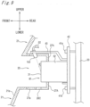
- the left LiDAR 6l and the left LC nozzle 106 are preferably arranged in further rear positions of the vehicle than a central part 28 of a front wheel (the tire 231) mounted to the vehicle 1. Also, the left LiDAR 6l and the left LC nozzle 106 are preferably arranged in positions lower than the top surface 24 of the tire 231. That is, the left LiDAR 6l and the left LC nozzle 106 are preferably arranged in positions lower than a reference line L1 shown in FIG. 10 . Also, the left LiDAR 61 and the left LC nozzle 106 are preferably arranged in the further rear position of the vehicle than the central part 28 (a reference line L2) of the tire 231.
- the left LiDAR 6l and the left LC nozzle 106 are provided to a fender mole 61 (an example of a design component configuring an outer appearance) attached to an upper side of the tire 231 of the vehicle 1.
- the positions in which the left LiDAR 6l and the left LC nozzle 106 are provided may also be positions (or vicinities) of a side emblem 62, a side mole 63 and the like (examples of the design component configuring the outer appearance).
- the left LiDAR 6l and the left LC nozzle 106 are preferably provided to the exterior component (design component) arranged on a side part of the vehicle 1.
- the left LC nozzle 106 is preferably integrated with the fender mole 61, the side emblem 62, the side mole 63 or the like.
- the description "integrated" indicates that the left LC nozzle 106 is formed integrally with the fender mole 61, the side emblem 62, the side mole 63 or the like, or that the left LC nozzle 106 is fixedly attached to the fender mole 61, the side emblem 62, the side mole 63 or the like.
- the left LC nozzle 106 is preferably provided in a position in which a distance between a side turn signal lamp 64 attached to the vehicle I and the left LC nozzle 106 is shorter than a distance between the tire 231 and the left LC nozzle 106.
- FIG. 11 is an enlarged view of the left LiDAR 6l and the left LC nozzle 106 shown in FIG. 10 .
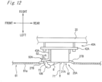
- FIG. 12 is a partial sectional view taken along a line B-B in FIG. 11 .
- the left LiDAR 6l is provided in a concave part 25A formed at the fender mole 61.
- the left LiDAR 6l is attached to the vehicle body 20 via an aiming mechanism 40A in the similar manner to the first embodiment.
- the left LiDAR 6l provided in the concave part 25A has a light receiving/emitting surface 31A (an example of the cleaning target surface) having a normal line 71 extending to a side of the vehicle 1 (in the example, a left side of the vehicle 1). That is, the light receiving/emitting surface 31A is provided to face toward the outside of the vehicle.
- the light receiving/emitting surface 31A is arranged further inside of the vehicle than a surface 61a of the fender mole 61.
- the vehicle 1 is provided with a cleaner 50A for cleaning the light receiving/emitting surface 31A of the left LiDAR 6l.
- a cleaner 50A for cleaning the light receiving/emitting surface 31A of the left LiDAR 6l.
- FIG. 12 the members of the cleaner 50A except the left LC nozzle 106 and the hose 52 are not shown.
- the left LC nozzle 106 is attached to a support component 43A, and is arranged in front of the left LiDAR 6l with respect to the vehicle.
- the support component 43A is attached to an aiming plate 42A of the aiming mechanism 40A. similarly to the first embodiment.
- the left LC nozzle 106 is arranged in a position further protruding outside of the vehicle (a leftward direction with respect to the vehicle 1) than the light receiving/emitting surface 31A during an operation of the cleaner 50A, i.e., in a state in which the light receiving/emitting surface 31A of the left LiDAR 61 is being cleaned.
- a direction of the front LC nozzle 103 is angle-adjusted so that the cleaning medium sprayed from a spraying hole of the left LC nozzle 106 is to be incident onto the light receiving/emitting surface 31A at an acute angle.
- An incidence angle ⁇ of the cleaning medium sprayed from the left LC nozzle 106 onto the light receiving/emitting surface 31A is, for example, 45° or smaller.
- the incidence angle ⁇ is 5° or greater and 30° or smaller.
- the left LC nozzle 106 is attached with a part of the left LC nozzle 106 being inserted in an insertion hole 72 formed in a bezel 27B provided on an outer periphery of the left LiDAR 6).
- the left LC nozzle 106 may be a fixed type nozzle or a pop-up type nozzle, similarly to the first embodiment.
- the bezel 27B is provided to conceal a gap from the fender mole 6l on the outer periphery of the left LiDAR 6l.
- the left LiDAR 6l and the left LC nozzle 106 provided on the left side part of the vehicle 1 have been described.
- the right LiDAR 6r and the right LC nozzle 105 provided on the right part of the vehicle 1 have also the similar configurations to the left LiDAR 6l and the left LC nozzle 106.
- the left LC nozzle 106 is provided in front of the left LiDAR 6l with respect to the vehicle, it is possible to spray the cleaning medium without opposing traveling wind. For this reason, it is possible to efficiently spray the cleaning medium toward the light receiving/emitting surface 31A of the left LiDAR 61 provided on the side part of the vehicle 1 and to clean the same.
- the cleaning medium is sprayed at an acute angle toward the light receiving/emitting surface 31A from the left LC nozzle 106 further protruding outside of the vehicle than the light receiving/emitting surface 31A. it is possible to efficiently clean the light receiving/emitting surface 31A.
- the left LiDAR 6l Since the left LiDAR 6l is arranged in at least one of the position lower than the top surface 24 of the tire 231 and the position at the rear of the central part 28 of the tire 231 with respect to the vehicle, the foreign matters (water droplets, mud, grit and dust, and the like) are likely to be attached thereto. Therefore, for the left LiDAR 6l arranged in the position, the left LC nozzle 106 provided in front of the left LiDAR 6l with respect to the vehicle is used, so that it is possible to efficiently remove the foreign matters attached on the left LiDAR 6l.
- the left LC nozzle 106 is integrated with the fender mole 61, the side emblem 62, the side mole 63 or the like. For this reason, the left LC nozzle becomes a part of a design of the corresponding member, so that it is possible to make the left LC nozzle 106 be unnoticeable from the outside.
- the left LC nozzle 106 is provided in the position in which the distance to the side turn signal lamp 64 is shorter than the distance to the tire 231. In this way, the left LC nozzle 106 is spaced from the tire 231 as much as possible, so that it is possible to prevent the left LC nozzle 106 from being clogged due to the foreign matters (water droplets, mud, grit and dust, and the like) agitated by the tire 231. Also, the left LC nozzle 106 is arranged close to the side turn signal lamp 64. so that it is possible to reduce an influence on the light emitted from the side turn signal lamp 64.
Applications Claiming Priority (5)
| Application Number | Priority Date | Filing Date | Title |
|---|---|---|---|
| JP2017180323 | 2017-09-20 | ||
| JP2017180321 | 2017-09-20 | ||
| JP2017180322 | 2017-09-20 | ||
| JP2017180320 | 2017-09-20 | ||
| PCT/JP2018/033961 WO2019059083A1 (ja) | 2017-09-20 | 2018-09-13 | 車両用センサシステム、当該車両用センサシステムを備えた車両、および車両 |
Publications (3)
| Publication Number | Publication Date |
|---|---|
| EP3686068A1 EP3686068A1 (en) | 2020-07-29 |
| EP3686068A4 EP3686068A4 (en) | 2021-06-09 |
| EP3686068B1 true EP3686068B1 (en) | 2023-08-30 |
Family
ID=65772432
Family Applications (1)
| Application Number | Title | Priority Date | Filing Date |
|---|---|---|---|
| EP18859749.6A Active EP3686068B1 (en) | 2017-09-20 | 2018-09-13 | Vehicle sensor system, vehicle provided with said vehicle sensor system |
Country Status (5)
| Country | Link |
|---|---|
| US (1) | US11912246B2 (ja) |
| EP (1) | EP3686068B1 (ja) |
| JP (1) | JP7223697B2 (ja) |
| CN (1) | CN109515389A (ja) |
| WO (1) | WO2019059083A1 (ja) |
Families Citing this family (12)
| Publication number | Priority date | Publication date | Assignee | Title |
|---|---|---|---|---|
| CN111845648B (zh) * | 2019-04-26 | 2023-02-17 | 上海禾赛科技有限公司 | 车载设备的清洁装置、清洁系统以及汽车 |
| EP3988404B1 (en) * | 2019-06-19 | 2024-04-17 | Koito Manufacturing Co., Ltd. | Vehicle cleaner system and sensor system with vehicle cleaner |
| WO2021131520A1 (ja) * | 2019-12-27 | 2021-07-01 | 株式会社小糸製作所 | センサユニット |
| US11760313B2 (en) * | 2020-04-30 | 2023-09-19 | Zoox, Inc. | Sensor pod cleaning system |
| US11623585B2 (en) | 2020-04-30 | 2023-04-11 | Zoox, Inc. | Sensor pod coverage and placement on vehicle |
| US11953623B2 (en) | 2020-04-30 | 2024-04-09 | Zoox, Inc. | Sensor pod assembly |
| US20220009453A1 (en) * | 2020-07-09 | 2022-01-13 | A. Raymond Et Cie | Bracket and modular assembly for fluid spray system |
| CN112157029A (zh) * | 2020-08-04 | 2021-01-01 | 西安外事学院 | 多功能传感器清洁器 |
| CN113917468A (zh) * | 2021-10-09 | 2022-01-11 | 武汉路特斯汽车有限公司 | 一种车载雷达系统及车辆 |
| CN116026382A (zh) * | 2021-10-25 | 2023-04-28 | 斯凯孚公司 | 传感器 |
| CN216387361U (zh) * | 2021-11-25 | 2022-04-26 | 经纬恒润(天津)研究开发有限公司 | 车用激光雷达支撑装置、车辆 |
| CN116351749A (zh) * | 2023-04-07 | 2023-06-30 | 合肥固泰自动化有限公司 | 一种自动除尘的自动装车车辆轮廓检测装置 |
Citations (2)
| Publication number | Priority date | Publication date | Assignee | Title |
|---|---|---|---|---|
| JP2006199203A (ja) * | 2005-01-21 | 2006-08-03 | Mazda Motor Corp | 車両の障害物検知装置 |
| JP2007024525A (ja) * | 2005-07-12 | 2007-02-01 | Honda Motor Co Ltd | 物体検知装置 |
Family Cites Families (43)
| Publication number | Priority date | Publication date | Assignee | Title |
|---|---|---|---|---|
| JPS5989273U (ja) * | 1982-12-07 | 1984-06-16 | 日産自動車株式会社 | レ−ザレ−ダ光軸調整装置 |
| JPS63200181U (ja) * | 1987-06-08 | 1988-12-23 | ||
| JP2515882Y2 (ja) * | 1990-09-25 | 1996-10-30 | 日野自動車工業株式会社 | 車間距離センサの傾き補正装置 |
| JPH0457469U (ja) * | 1990-09-26 | 1992-05-18 | ||
| JP2002303672A (ja) * | 2001-04-04 | 2002-10-18 | Honda Motor Co Ltd | 物体検知装置の軸調整状態検知方法および軸調整方法 |
| US8139109B2 (en) * | 2006-06-19 | 2012-03-20 | Oshkosh Corporation | Vision system for an autonomous vehicle |
| US10432827B2 (en) * | 2011-03-10 | 2019-10-01 | Dlhbowles, Inc. | Integrated automotive system, nozzle assembly and remote control method for cleaning an image sensors exterior or objective lens surface |
| CN102849032B (zh) * | 2011-06-29 | 2015-05-27 | 比亚迪股份有限公司 | 一种汽车前大灯洗涤系统及洗涤方法 |
| JP2013018404A (ja) | 2011-07-12 | 2013-01-31 | Asmo Co Ltd | 車載カメラ用ウォッシャノズル |
| WO2014010578A1 (ja) * | 2012-07-11 | 2014-01-16 | 日産自動車株式会社 | 車載カメラの洗浄装置及び車載カメラの洗浄方法 |
| JP5803831B2 (ja) * | 2012-07-23 | 2015-11-04 | 株式会社デンソー | 車載光学センサ用洗浄装置 |
| JP2014201150A (ja) * | 2013-04-03 | 2014-10-27 | クラリオン株式会社 | 車載用撮像装置、光学部材の汚れ防止方法、及び、カメラモジュール |
| US8983705B2 (en) | 2013-04-30 | 2015-03-17 | Google Inc. | Methods and systems for detecting weather conditions including fog using vehicle onboard sensors |
| KR102040353B1 (ko) | 2013-04-11 | 2019-11-04 | 웨이모 엘엘씨 | 차량 온보드 센서들을 사용하여 날씨 상태들을 검출하는 방법들 및 시스템들 |
| US9207323B2 (en) | 2013-04-11 | 2015-12-08 | Google Inc. | Methods and systems for detecting weather conditions including wet surfaces using vehicle onboard sensors |
| US9025140B2 (en) | 2013-05-07 | 2015-05-05 | Google Inc. | Methods and systems for detecting weather conditions including sunlight using vehicle onboard sensors |
| US9632210B2 (en) | 2013-05-07 | 2017-04-25 | Google Inc. | Methods and systems for detecting weather conditions using vehicle onboard sensors |
| US10247854B2 (en) | 2013-05-07 | 2019-04-02 | Waymo Llc | Methods and systems for detecting weather conditions using vehicle onboard sensors |
| EP2845773B1 (en) * | 2013-09-10 | 2021-09-08 | dlhBowles Inc. | Integrated automotive system, pop-up nozzle assembly and remote control method for cleaning a wide-angle image sensor's exterior surface |
| JP6417757B2 (ja) * | 2013-09-19 | 2018-11-07 | 株式会社デンソー | 車載光学センサ洗浄装置 |
| KR20150035204A (ko) * | 2013-09-27 | 2015-04-06 | 한국전자통신연구원 | 차량용 거리측정센서의 오염제거장치 및 방법 |
| WO2015068249A1 (ja) | 2013-11-08 | 2015-05-14 | 株式会社日立製作所 | 自律走行車両、及び自律走行システム |
| DE102014010495B3 (de) * | 2014-07-16 | 2015-12-17 | Kautex Textron Gmbh & Co. Kg | Fahrzeugintegriertes Sicht- und Reinigungssystem |
| FR3026031B1 (fr) | 2014-09-23 | 2017-06-09 | Valeo Systemes Dessuyage | Dispositif de protection d'un capteur optique |
| JP6447305B2 (ja) | 2015-03-30 | 2019-01-09 | トヨタ自動車株式会社 | 車両用周辺情報検出構造 |
| DE102016107380A1 (de) | 2015-05-20 | 2016-11-24 | Asmo Co., Ltd. | Anlage zur Reinigung eines fahrzeugeigenen optischen Sensors und Verfahren dafür |
| JP6700584B2 (ja) * | 2016-01-19 | 2020-05-27 | 株式会社デンソー | 車載光学センサ洗浄装置 |
| US10661761B2 (en) | 2015-06-30 | 2020-05-26 | Koito Manufacturing Co., Ltd. | Foreign matter removal device and vehicle equipped with foreign matter removal device |
| JP6621298B2 (ja) * | 2015-10-28 | 2019-12-18 | 武蔵精密工業株式会社 | 差動装置 |
| WO2017119364A1 (ja) | 2016-01-07 | 2017-07-13 | シャープ株式会社 | 走行車両 |
| US10807594B2 (en) | 2016-03-07 | 2020-10-20 | Honda Motor Co., Ltd. | Vehicle control device, vehicle control method, and vehicle control program |
| JP6591337B2 (ja) | 2016-03-30 | 2019-10-16 | 愛三工業株式会社 | 蒸発燃料処理装置 |
| JP6559606B2 (ja) | 2016-03-30 | 2019-08-14 | 愛三工業株式会社 | 蒸発燃料処理装置 |
| JP6587967B2 (ja) | 2016-03-30 | 2019-10-09 | 愛三工業株式会社 | 蒸発燃料処理装置 |
| JP2017180323A (ja) | 2016-03-30 | 2017-10-05 | 大阪瓦斯株式会社 | 冷熱利用発電設備 |
| US10189450B2 (en) * | 2016-07-18 | 2019-01-29 | Uber Technologies, Inc. | Sensor cleaning system for vehicles |
| FR3056524B1 (fr) | 2016-09-28 | 2018-10-12 | Valeo Systemes D'essuyage | Systeme de detection pour vehicule automobile |
| CN106341609A (zh) | 2016-11-11 | 2017-01-18 | 清华大学苏州汽车研究院(吴江) | 基于电路控制的驾驶员视频监控系统的图像对准装置 |
| US10515390B2 (en) * | 2016-11-21 | 2019-12-24 | Nio Usa, Inc. | Method and system for data optimization |
| DE112018000478T5 (de) | 2017-01-23 | 2019-10-24 | Koito Manufacturing Co., Ltd. | Fahrzeug-Reinigersystem und Fahrzeug mit Fahrzeug-Reinigersystem |
| US10703341B2 (en) | 2017-02-03 | 2020-07-07 | Magna Electronics Inc. | Vehicle sensor housing with theft protection |
| US10286880B2 (en) * | 2017-03-24 | 2019-05-14 | Ford Global Technologies, Llc | Sensor cleaner |
| JP2019194529A (ja) * | 2018-05-01 | 2019-11-07 | 株式会社小糸製作所 | 車両用ランプのエイミング調整方法及びエイミング調整装置 |
-
2018
- 2018-09-13 WO PCT/JP2018/033961 patent/WO2019059083A1/ja unknown
- 2018-09-13 JP JP2019543597A patent/JP7223697B2/ja active Active
- 2018-09-13 US US16/648,942 patent/US11912246B2/en active Active
- 2018-09-13 EP EP18859749.6A patent/EP3686068B1/en active Active
- 2018-09-20 CN CN201811103129.XA patent/CN109515389A/zh active Pending
Patent Citations (2)
| Publication number | Priority date | Publication date | Assignee | Title |
|---|---|---|---|---|
| JP2006199203A (ja) * | 2005-01-21 | 2006-08-03 | Mazda Motor Corp | 車両の障害物検知装置 |
| JP2007024525A (ja) * | 2005-07-12 | 2007-02-01 | Honda Motor Co Ltd | 物体検知装置 |
Also Published As
| Publication number | Publication date |
|---|---|
| US11912246B2 (en) | 2024-02-27 |
| EP3686068A4 (en) | 2021-06-09 |
| CN109515389A (zh) | 2019-03-26 |
| EP3686068A1 (en) | 2020-07-29 |
| JP7223697B2 (ja) | 2023-02-16 |
| WO2019059083A1 (ja) | 2019-03-28 |
| US20200247367A1 (en) | 2020-08-06 |
| JPWO2019059083A1 (ja) | 2020-10-15 |
Similar Documents
| Publication | Publication Date | Title |
|---|---|---|
| EP3686068B1 (en) | Vehicle sensor system, vehicle provided with said vehicle sensor system | |
| EP3640099B1 (en) | Vehicle cleaner system and vehicle provided with vehicle cleaner system | |
| CN111201166B (zh) | 车辆用清洗系统 | |
| JP6981218B2 (ja) | 車両用洗浄システム | |
| JP7362592B2 (ja) | 車両用クリーナシステム、車両システム、車両用クリーナシステムによる洗浄方法、車両用クリーナ制御装置 | |
| KR102649924B1 (ko) | 주변 센서 하우징 | |
| US11667268B2 (en) | Vehicle cleaner system and vehicle system | |
| CN111867896B (zh) | 车辆用清洁系统 | |
| CN110958962A (zh) | 车辆用清洁系统及车辆用清洁器控制装置 | |
| US20230031726A1 (en) | Sensor unit | |
| EP3763583A1 (en) | Vehicle cleaner system | |
| JP7182053B2 (ja) | 車両用洗浄システム | |
| JP7236800B2 (ja) | 車両洗浄システム | |
| US10780821B2 (en) | System for alerting a vehicle occupant to a ground surface condition adjacent a vehicle door | |
| CN209191896U (zh) | 车辆用传感器系统和包括该车辆用传感器系统的车辆 | |
| JP2020078998A (ja) | 車両用クリーナシステム | |
| CN209176649U (zh) | 车辆用传感器系统和具有该车辆用传感器系统的车辆 |
Legal Events
| Date | Code | Title | Description |
|---|---|---|---|
| STAA | Information on the status of an ep patent application or granted ep patent |
Free format text: STATUS: THE INTERNATIONAL PUBLICATION HAS BEEN MADE |
|
| PUAI | Public reference made under article 153(3) epc to a published international application that has entered the european phase |
Free format text: ORIGINAL CODE: 0009012 |
|
| STAA | Information on the status of an ep patent application or granted ep patent |
Free format text: STATUS: REQUEST FOR EXAMINATION WAS MADE |
|
| 17P | Request for examination filed |
Effective date: 20200320 |
|
| AK | Designated contracting states |
Kind code of ref document: A1 Designated state(s): AL AT BE BG CH CY CZ DE DK EE ES FI FR GB GR HR HU IE IS IT LI LT LU LV MC MK MT NL NO PL PT RO RS SE SI SK SM TR |
|
| AX | Request for extension of the european patent |
Extension state: BA ME |
|
| DAV | Request for validation of the european patent (deleted) | ||
| DAX | Request for extension of the european patent (deleted) | ||
| A4 | Supplementary search report drawn up and despatched |
Effective date: 20210511 |
|
| RIC1 | Information provided on ipc code assigned before grant |
Ipc: B60S 1/60 20060101AFI20210504BHEP Ipc: B08B 3/02 20060101ALI20210504BHEP Ipc: G01N 21/49 20060101ALI20210504BHEP Ipc: B60S 1/56 20060101ALI20210504BHEP Ipc: B60R 11/04 20060101ALI20210504BHEP |
|
| GRAP | Despatch of communication of intention to grant a patent |
Free format text: ORIGINAL CODE: EPIDOSNIGR1 |
|
| STAA | Information on the status of an ep patent application or granted ep patent |
Free format text: STATUS: GRANT OF PATENT IS INTENDED |
|
| INTG | Intention to grant announced |
Effective date: 20230314 |
|
| RIN1 | Information on inventor provided before grant (corrected) |
Inventor name: SAKAI, MASARU |
|
| GRAS | Grant fee paid |
Free format text: ORIGINAL CODE: EPIDOSNIGR3 |
|
| GRAA | (expected) grant |
Free format text: ORIGINAL CODE: 0009210 |
|
| STAA | Information on the status of an ep patent application or granted ep patent |
Free format text: STATUS: THE PATENT HAS BEEN GRANTED |
|
| AK | Designated contracting states |
Kind code of ref document: B1 Designated state(s): AL AT BE BG CH CY CZ DE DK EE ES FI FR GB GR HR HU IE IS IT LI LT LU LV MC MK MT NL NO PL PT RO RS SE SI SK SM TR |
|
| REG | Reference to a national code |
Ref country code: GB Ref legal event code: FG4D |
|
| REG | Reference to a national code |
Ref country code: CH Ref legal event code: EP |
|
| REG | Reference to a national code |
Ref country code: DE Ref legal event code: R096 Ref document number: 602018056679 Country of ref document: DE |
|
| P01 | Opt-out of the competence of the unified patent court (upc) registered |
Effective date: 20230815 |
|
| REG | Reference to a national code |
Ref country code: IE Ref legal event code: FG4D |
|
| PGFP | Annual fee paid to national office [announced via postgrant information from national office to epo] |
Ref country code: FR Payment date: 20230921 Year of fee payment: 6 Ref country code: DE Payment date: 20230912 Year of fee payment: 6 |
|
| REG | Reference to a national code |
Ref country code: LT Ref legal event code: MG9D |
|
| REG | Reference to a national code |
Ref country code: NL Ref legal event code: MP Effective date: 20230830 |
|
| REG | Reference to a national code |
Ref country code: AT Ref legal event code: MK05 Ref document number: 1605055 Country of ref document: AT Kind code of ref document: T Effective date: 20230830 |
|
| PG25 | Lapsed in a contracting state [announced via postgrant information from national office to epo] |
Ref country code: GR Free format text: LAPSE BECAUSE OF FAILURE TO SUBMIT A TRANSLATION OF THE DESCRIPTION OR TO PAY THE FEE WITHIN THE PRESCRIBED TIME-LIMIT Effective date: 20231201 |
|
| PG25 | Lapsed in a contracting state [announced via postgrant information from national office to epo] |
Ref country code: IS Free format text: LAPSE BECAUSE OF FAILURE TO SUBMIT A TRANSLATION OF THE DESCRIPTION OR TO PAY THE FEE WITHIN THE PRESCRIBED TIME-LIMIT Effective date: 20231230 |
|
| PG25 | Lapsed in a contracting state [announced via postgrant information from national office to epo] |
Ref country code: SE Free format text: LAPSE BECAUSE OF FAILURE TO SUBMIT A TRANSLATION OF THE DESCRIPTION OR TO PAY THE FEE WITHIN THE PRESCRIBED TIME-LIMIT Effective date: 20230830 Ref country code: RS Free format text: LAPSE BECAUSE OF FAILURE TO SUBMIT A TRANSLATION OF THE DESCRIPTION OR TO PAY THE FEE WITHIN THE PRESCRIBED TIME-LIMIT Effective date: 20230830 Ref country code: NO Free format text: LAPSE BECAUSE OF FAILURE TO SUBMIT A TRANSLATION OF THE DESCRIPTION OR TO PAY THE FEE WITHIN THE PRESCRIBED TIME-LIMIT Effective date: 20231130 Ref country code: LV Free format text: LAPSE BECAUSE OF FAILURE TO SUBMIT A TRANSLATION OF THE DESCRIPTION OR TO PAY THE FEE WITHIN THE PRESCRIBED TIME-LIMIT Effective date: 20230830 Ref country code: LT Free format text: LAPSE BECAUSE OF FAILURE TO SUBMIT A TRANSLATION OF THE DESCRIPTION OR TO PAY THE FEE WITHIN THE PRESCRIBED TIME-LIMIT Effective date: 20230830 Ref country code: IS Free format text: LAPSE BECAUSE OF FAILURE TO SUBMIT A TRANSLATION OF THE DESCRIPTION OR TO PAY THE FEE WITHIN THE PRESCRIBED TIME-LIMIT Effective date: 20231230 Ref country code: HR Free format text: LAPSE BECAUSE OF FAILURE TO SUBMIT A TRANSLATION OF THE DESCRIPTION OR TO PAY THE FEE WITHIN THE PRESCRIBED TIME-LIMIT Effective date: 20230830 Ref country code: GR Free format text: LAPSE BECAUSE OF FAILURE TO SUBMIT A TRANSLATION OF THE DESCRIPTION OR TO PAY THE FEE WITHIN THE PRESCRIBED TIME-LIMIT Effective date: 20231201 Ref country code: FI Free format text: LAPSE BECAUSE OF FAILURE TO SUBMIT A TRANSLATION OF THE DESCRIPTION OR TO PAY THE FEE WITHIN THE PRESCRIBED TIME-LIMIT Effective date: 20230830 Ref country code: AT Free format text: LAPSE BECAUSE OF FAILURE TO SUBMIT A TRANSLATION OF THE DESCRIPTION OR TO PAY THE FEE WITHIN THE PRESCRIBED TIME-LIMIT Effective date: 20230830 |
|
| PG25 | Lapsed in a contracting state [announced via postgrant information from national office to epo] |
Ref country code: PL Free format text: LAPSE BECAUSE OF FAILURE TO SUBMIT A TRANSLATION OF THE DESCRIPTION OR TO PAY THE FEE WITHIN THE PRESCRIBED TIME-LIMIT Effective date: 20230830 Ref country code: NL Free format text: LAPSE BECAUSE OF FAILURE TO SUBMIT A TRANSLATION OF THE DESCRIPTION OR TO PAY THE FEE WITHIN THE PRESCRIBED TIME-LIMIT Effective date: 20230830 |