EP3682127B1 - Anordnung mit befestigungselement zum lösbaren verbinden von zwei bauelementen - Google Patents
Anordnung mit befestigungselement zum lösbaren verbinden von zwei bauelementen Download PDFInfo
- Publication number
- EP3682127B1 EP3682127B1 EP18770003.4A EP18770003A EP3682127B1 EP 3682127 B1 EP3682127 B1 EP 3682127B1 EP 18770003 A EP18770003 A EP 18770003A EP 3682127 B1 EP3682127 B1 EP 3682127B1
- Authority
- EP
- European Patent Office
- Prior art keywords
- component
- fastening element
- receptacle
- installation direction
- arrangement according
- Prior art date
- Legal status (The legal status is an assumption and is not a legal conclusion. Google has not performed a legal analysis and makes no representation as to the accuracy of the status listed.)
- Active
Links
Images



Classifications
-
- F—MECHANICAL ENGINEERING; LIGHTING; HEATING; WEAPONS; BLASTING
- F16—ENGINEERING ELEMENTS AND UNITS; GENERAL MEASURES FOR PRODUCING AND MAINTAINING EFFECTIVE FUNCTIONING OF MACHINES OR INSTALLATIONS; THERMAL INSULATION IN GENERAL
- F16B—DEVICES FOR FASTENING OR SECURING CONSTRUCTIONAL ELEMENTS OR MACHINE PARTS TOGETHER, e.g. NAILS, BOLTS, CIRCLIPS, CLAMPS, CLIPS OR WEDGES; JOINTS OR JOINTING
- F16B21/00—Means for preventing relative axial movement of a pin, spigot, shaft or the like and a member surrounding it; Stud-and-socket releasable fastenings
- F16B21/06—Releasable fastening devices with snap-action
- F16B21/08—Releasable fastening devices with snap-action in which the stud, pin, or spigot has a resilient part
- F16B21/082—Releasable fastening devices with snap-action in which the stud, pin, or spigot has a resilient part the stud, pin or spigot having two resilient parts on its opposite ends in order to connect two elements
-
- B—PERFORMING OPERATIONS; TRANSPORTING
- B60—VEHICLES IN GENERAL
- B60Q—ARRANGEMENT OF SIGNALLING OR LIGHTING DEVICES, THE MOUNTING OR SUPPORTING THEREOF OR CIRCUITS THEREFOR, FOR VEHICLES IN GENERAL
- B60Q1/00—Arrangement of optical signalling or lighting devices, the mounting or supporting thereof or circuits therefor
- B60Q1/26—Arrangement of optical signalling or lighting devices, the mounting or supporting thereof or circuits therefor the devices being primarily intended to indicate the vehicle, or parts thereof, or to give signals, to other traffic
- B60Q1/2619—Arrangement of optical signalling or lighting devices, the mounting or supporting thereof or circuits therefor the devices being primarily intended to indicate the vehicle, or parts thereof, or to give signals, to other traffic built in the vehicle body
- B60Q1/2623—Details of the fastening means
- B60Q1/263—Snap-in fasteners
-
- F—MECHANICAL ENGINEERING; LIGHTING; HEATING; WEAPONS; BLASTING
- F16—ENGINEERING ELEMENTS AND UNITS; GENERAL MEASURES FOR PRODUCING AND MAINTAINING EFFECTIVE FUNCTIONING OF MACHINES OR INSTALLATIONS; THERMAL INSULATION IN GENERAL
- F16B—DEVICES FOR FASTENING OR SECURING CONSTRUCTIONAL ELEMENTS OR MACHINE PARTS TOGETHER, e.g. NAILS, BOLTS, CIRCLIPS, CLAMPS, CLIPS OR WEDGES; JOINTS OR JOINTING
- F16B21/00—Means for preventing relative axial movement of a pin, spigot, shaft or the like and a member surrounding it; Stud-and-socket releasable fastenings
- F16B21/06—Releasable fastening devices with snap-action
- F16B21/08—Releasable fastening devices with snap-action in which the stud, pin, or spigot has a resilient part
- F16B21/086—Releasable fastening devices with snap-action in which the stud, pin, or spigot has a resilient part the shank of the stud, pin or spigot having elevations, ribs, fins or prongs intended for deformation or tilting predominantly in a direction perpendicular to the direction of insertion
-
- F—MECHANICAL ENGINEERING; LIGHTING; HEATING; WEAPONS; BLASTING
- F16—ENGINEERING ELEMENTS AND UNITS; GENERAL MEASURES FOR PRODUCING AND MAINTAINING EFFECTIVE FUNCTIONING OF MACHINES OR INSTALLATIONS; THERMAL INSULATION IN GENERAL
- F16B—DEVICES FOR FASTENING OR SECURING CONSTRUCTIONAL ELEMENTS OR MACHINE PARTS TOGETHER, e.g. NAILS, BOLTS, CIRCLIPS, CLAMPS, CLIPS OR WEDGES; JOINTS OR JOINTING
- F16B5/00—Joining sheets or plates, e.g. panels, to one another or to strips or bars parallel to them
- F16B5/06—Joining sheets or plates, e.g. panels, to one another or to strips or bars parallel to them by means of clamps or clips
- F16B5/0607—Joining sheets or plates, e.g. panels, to one another or to strips or bars parallel to them by means of clamps or clips joining sheets or plates to each other
- F16B5/0621—Joining sheets or plates, e.g. panels, to one another or to strips or bars parallel to them by means of clamps or clips joining sheets or plates to each other in parallel relationship
- F16B5/0628—Joining sheets or plates, e.g. panels, to one another or to strips or bars parallel to them by means of clamps or clips joining sheets or plates to each other in parallel relationship allowing for adjustment parallel or perpendicular to the plane of the sheets or plates
-
- F—MECHANICAL ENGINEERING; LIGHTING; HEATING; WEAPONS; BLASTING
- F16—ENGINEERING ELEMENTS AND UNITS; GENERAL MEASURES FOR PRODUCING AND MAINTAINING EFFECTIVE FUNCTIONING OF MACHINES OR INSTALLATIONS; THERMAL INSULATION IN GENERAL
- F16B—DEVICES FOR FASTENING OR SECURING CONSTRUCTIONAL ELEMENTS OR MACHINE PARTS TOGETHER, e.g. NAILS, BOLTS, CIRCLIPS, CLAMPS, CLIPS OR WEDGES; JOINTS OR JOINTING
- F16B5/00—Joining sheets or plates, e.g. panels, to one another or to strips or bars parallel to them
- F16B5/06—Joining sheets or plates, e.g. panels, to one another or to strips or bars parallel to them by means of clamps or clips
- F16B5/0607—Joining sheets or plates, e.g. panels, to one another or to strips or bars parallel to them by means of clamps or clips joining sheets or plates to each other
- F16B5/0621—Joining sheets or plates, e.g. panels, to one another or to strips or bars parallel to them by means of clamps or clips joining sheets or plates to each other in parallel relationship
- F16B5/065—Joining sheets or plates, e.g. panels, to one another or to strips or bars parallel to them by means of clamps or clips joining sheets or plates to each other in parallel relationship the plates being one on top of the other and distanced from each other, e.g. by using protrusions to keep contact and distance
-
- F—MECHANICAL ENGINEERING; LIGHTING; HEATING; WEAPONS; BLASTING
- F16—ENGINEERING ELEMENTS AND UNITS; GENERAL MEASURES FOR PRODUCING AND MAINTAINING EFFECTIVE FUNCTIONING OF MACHINES OR INSTALLATIONS; THERMAL INSULATION IN GENERAL
- F16B—DEVICES FOR FASTENING OR SECURING CONSTRUCTIONAL ELEMENTS OR MACHINE PARTS TOGETHER, e.g. NAILS, BOLTS, CIRCLIPS, CLAMPS, CLIPS OR WEDGES; JOINTS OR JOINTING
- F16B5/00—Joining sheets or plates, e.g. panels, to one another or to strips or bars parallel to them
- F16B5/06—Joining sheets or plates, e.g. panels, to one another or to strips or bars parallel to them by means of clamps or clips
- F16B5/0607—Joining sheets or plates, e.g. panels, to one another or to strips or bars parallel to them by means of clamps or clips joining sheets or plates to each other
- F16B5/0621—Joining sheets or plates, e.g. panels, to one another or to strips or bars parallel to them by means of clamps or clips joining sheets or plates to each other in parallel relationship
- F16B5/0664—Joining sheets or plates, e.g. panels, to one another or to strips or bars parallel to them by means of clamps or clips joining sheets or plates to each other in parallel relationship at least one of the sheets or plates having integrally formed or integrally connected snap-in-features
Definitions
- the invention relates to an arrangement for releasably connecting two components with the features mentioned in the preamble of claim 1.
- US 6,406,242 B1 also discloses a connecting element in which an additional lock is provided.
- the invention is based on the object of creating an arrangement by means of which a secure and releasable fixation of two components to one another is possible.
- the starting point of the invention is the arrangement of a fastening element for releasably connecting two components, which comprises a base body which has at least one latching element for connecting to a first component, wherein the latching element can be inserted into a corresponding opening of the first component in a first assembly direction, whereby the base body has on its side opposite the locking element a receptacle for at least a section of a second component, the receptacle and the section having corresponding shape features which guide the second component in the first assembly direction, in a second assembly direction and a third assembly direction and the receptacle and the second component have corresponding locking means, which serve to releasably fix the second component in the second assembly direction, the receptacle forming an insertion area for the section of the second component in the assembly direction.
- a support surface is formed on the side of the base body facing the insertion area, which merges via a ramp into a front end edge of the base body, the ramp and the support surface being arranged in the area of a gap which is formed by rear walls and upper end walls of the Fastening element for receiving a guide area of the section of the second component is formed, wherein a step of a projection of the second component engages behind a step of the support surface of the base body in the interaction of the section of the second component with the receptacle of the fastening element and a stop surface of a locking area of the section on stop surfaces of the recording hits.
- the insertion area is formed by side boundary walls, rear walls and upper end walls. This advantageously makes it possible to guide the section of the second component precisely and reproducibly in relation to the fastening element.
- a distance between the support surface and the contact surfaces of the insertion area is smaller than a height of the locking area and thus the distance between the contact surfaces of the locking area. This ensures play-free guidance of the section of the second component in the insertion area.
- a distance between the support surface and the contact surfaces is smaller than a height of the locking area.
- the locking area has a projection on its contact surface assigned to the support surface, which merges into the contact surface via the step of the projection.
- the steps run at an angle to the first assembly direction. This advantageously makes it possible to achieve a defined, precise latching in the second assembly direction by means of the corresponding steps, on the one hand on the fastening element and on the other hand on the section of the second component. It is also advantageously possible to define a holding force by selecting the angle, by means of which the second component is releasably fixed in the fastening element.
- the second component is a vehicle light and the first component is a body section of a vehicle body.
- Arrangement allows a defined, precise and reproducible positioning of a vehicle light on the vehicle body.
- Figure 1 shows an arrangement of a fastening element 10, which serves to releasably connect a first component 12 to a second component 14.
- the fastening element 10 has a base body 16, on one side of which a locking element 18 is formed.
- a receptacle 20 is formed on the side of the base body 16 facing away from the locking element 18.
- the first component 12 has an opening 22 which corresponds to the locking element 18 of the fastening element 10.
- the receptacle 20 forms an insertion area 24 for a correspondingly designed section 26 of the second component 14.
- Section 26 can be an integral part of the second component 14 or is arranged on it in addition to the connection to the fastening element 10.
- the arrangement shown shows the following function:
- the fastening element 10 is inserted with its locking element 18 into the opening 22 of the first component 12.
- the spring legs 28 of the locking element 18 are first compressed so that the locking element 18 can pass through the opening 22.
- the sealing element 30 also has an opening 32 through which the locking element 18 passes.
- the sealing element 30 is arranged between the base body 16 of the fastening element 10 and a top side 34 of the first component 12.
- the spring legs 28 rest on an underside 36 of the first component 12.
- the fastening element 10 and the first component 12 are thus fixed in the first assembly direction Y.
- This fixation between the fastening element 10 and the first component 12 can also be canceled again using measures that cannot be considered in detail here by compressing the spring legs 28 on the underside 36 of the first component 12 and thus moving the fastening element 10 against the first assembly direction Y from the first Component 12 is removed.
- the first assembly direction Y is marked by a double arrow 38.
- the fastening element 10 is thus mounted on the first component 12 so that it cannot rotate in all three spatial directions.
- the second component 14 is pushed with its section 26 into the insertion area 24 of the receptacle 20.
- the section 26 and the insertion area 24 have corresponding ones Shape features - which will be discussed in more detail with reference to the following figures - so that a guide for the second component 14 in the first assembly direction Y, in a second assembly direction X and a third assembly direction Z results.
- the receptacle 20 is formed by side boundary walls 44, rear walls 46 and upper end walls 48.
- the boundary walls 44, rear walls 46 and end walls 48 are formed in one piece with the fastening element 10.
- a continuous gap 50 is formed between the rear walls 46 and the end walls 48.
- a support surface 52 is formed, which merges into a front end edge 56 of the base body 16 via a ramp 54. In the direction of the rear walls 46, the support surface 52 passes over a step 58 of the support surface 52 to the top of the base body 16.
- the ramp 54 and the support surface 52 are arranged in the area of the gap 50.
- the end walls 48 form contact surfaces 60 on their longitudinal edges facing the gap 50 and the insertion area 24. There is a distance a between the support surface 52 and the contact surfaces 60.
- the side boundary walls 44 form stop surfaces 62.
- the insides of the boundary walls 44 are arranged at a distance b from one another.
- the insertion area has a depth t.
- Section 26 of the second component 14 is shown in a schematic perspective view.
- the section 26 has a guide area 64 and a locking area 66.
- the locking area 66 has lateral guide surfaces 68 as well as an upper contact surface 70 and a lower contact surface 72. The distance between the contact surfaces 70 and 72 from one another determines a height h of the locking area 66.
- the guide surfaces 68 merge into the end face 74 at a first end face 74 via contact surfaces 76. This means that the locking area 66 tapers in the direction of the end face 74.
- Stop surfaces 80 are formed on the end face 78 of the locking region 66 opposite the end face 74.
- a nose-like projection 84 extends from an underside 82 of the locking area 66, which merges in the direction of the end face 78 over a step 86 of the projection 84 and in the direction of the end face 74 over an incline 88 into the underside 82 and thus into the contact surface 72.
- Figure 6 shows a sectional view through a second component 14 fixed by means of the fastening element 10.
- the section 26 is inserted with its guide area 64 into the gap 50 of the receptacle 20 in the second assembly direction X.
- the guide surfaces 68 of the locking area 66 come into contact with the side boundary walls 44.
- the distance b of the boundary walls 44 corresponds to the width of the locking area 66, so that a defined insertion of the section 26 into the receptacle 20 in the second assembly direction X is possible.
- the height h of the locking area 66 is slightly larger than the distance a between the support surface 52 and the contact surfaces 60. This ensures that when the section 26 is inserted into the receptacle 20, the upper end walls 48 of the fastening element 10 are slightly displaced in the first assembly direction Y .
- the section 26 is pushed into the receptacle 20 until the step 86 of the projection 84 locks with the step 58 of the support surface 52. In this position, the upper end surfaces 48 with their contact surfaces 60 push towards the contact surface 70 of the locking area 66 due to the elasticity inherent in the material of the fastening element 10. The section 26 and thus the second component 14 is thus securely fixed in the first assembly direction Y.
- the stop surface 80 of the locking area 66 abuts the stop surfaces 62 of the receptacle 20.
- the section 26 and thus the second component 14 is securely fixed in the second assembly direction X. There will be a defined position of the second component 14 in relation to the fastening element 10 and thus also in relation to the first component 12.
- the steps 86 and 58 run at an angle ⁇ to the first assembly direction Y.
- the size of the angle ⁇ determines the holding force of the fastening element 10 in relation to the second component 14.
- the angle ⁇ is, for example, 1 - 3 °.
- the dismantling angle ⁇ determines the dismantling force. The larger the angle ⁇ , the smaller the dismantling force is.
- the second component 14 can be, for example, a vehicle light 94, in particular a rear light of a vehicle 90.
- the first component 12 is, for example, a body section of a vehicle body 92.
- a vehicle 90 is shown for this purpose.
- a vehicle light 94 (here a tail light) is arranged on a vehicle body 92.
- the fastening element 10 thus makes it possible to releasably fix the vehicle light 94 with a simultaneous defined alignment in the X direction, Y direction and Z direction on the vehicle body 92.
- gap formation between the vehicle light 94 and the vehicle body 92 can be prevented or minimized.
Landscapes
- Engineering & Computer Science (AREA)
- General Engineering & Computer Science (AREA)
- Mechanical Engineering (AREA)
- Insertion Pins And Rivets (AREA)
- Snaps, Bayonet Connections, Set Pins, And Snap Rings (AREA)
- Lighting Device Outwards From Vehicle And Optical Signal (AREA)
Description
- Die Erfindung betrifft eine Anordnung zum lösbaren Verbinden von zwei Bauelementen mit den im Oberbegriff des Anspruchs 1 genannten Merkmalen.
- Aus
DE 10 2004 030 583 A1 ist hierzu beispielsweise eine zweiteilige Schiebebeziehungsweise Gleithalterung bekannt. -
US 6,406,242 B1 offenbart ebenfalls ein Verbindungselement, bei der ein zusätzlicher Feststeller vorgesehen ist. - Aus der
US 2016/288733 A1 ist eine Struktur bekannt, in der eine Cliphaltekomponente eines Kabelbaumschutzes beschrieben ist, wobei ein Clip mit der Cliphaltekomponente zusammenpasst. - Der Erfindung liegt die Aufgabe zugrunde, eine Anordnung zu schaffen, mittels der eine sichere und lösbare Fixierung von zwei Bauelementen zueinander möglich ist.
- Ausgangspunkt der Erfindung ist die Anordnung eines Befestigungselementes zum lösbaren Verbinden von zwei Bauelementen, welches einen Grundkörper umfasst, der zumindest ein Rastelement zum Verbinden mit einem ersten Bauelement aufweist, wobei das Rastelement in eine korrespondierende Öffnung des ersten Bauelementes in einer ersten Montagerichtung einbringbar ist, wobei der Grundkörper an seiner dem Rastelement gegenüberliegenden Seite eine Aufnahme für zumindest einen Abschnitt eines zweiten Bauelementes aufweist, wobei die Aufnahme und der Abschnitt korrespondierende Formmerkmale aufweisen, die eine Führung des zweiten Bauelementes in der ersten Montagerichtung, in einer zweiten Montagerichtung und einer dritten Montagerichtung übernehmen und die Aufnahme und das zweite Bauelement korrespondierende Rastmittel aufweisen, die einer lösbaren Fixierung des zweiten Bauelementes in der zweiten Montagerichtung dienen, wobei die Aufnahme einen Einschubbereich für den Abschnitt des zweiten Bauelementes in der Montagerichtung ausbildet.
- Erfindungsgemäß ist vorgesehen, dass auf der dem Einschubbereich zugewandten Seite des Grundkörpers eine Auflagefläche ausgebildet ist, die über eine Rampe in eine vordere Abschlusskante des Grundkörpers übergeht, wobei die Rampe und die Auflagefläche im Bereich eines Spaltes angeordnet sind, der durch Rückwände und obere Abschlusswände des Befestigungselements zur Aufnahme eines Führungsbereiches des Abschnittes des zweiten Bauelementes gebildet ist, wobei eine Stufe eines Vorsprunges des zweiten Bauelementes im Zusammenwirken des Abschnittes des zweiten Bauelementes mit der Aufnahme des Befestigungselementes eine Stufe der Auflagefläche des Grundkörpers hinterrastet und eine Anschlagfläche eines Arretierungsbereiches des Abschnittes an Anschlagflächen der Aufnahme anschlägt.
- Bevorzugt ist vorgesehen, dass der Einschubbereich von seitlichen Begrenzungswänden, Rückwänden und oberen Abschlusswänden gebildet ist. Hierdurch wird vorteilhaft möglich, den Abschnitt des zweiten Bauelementes in Bezug auf das Befestigungselement genau und reproduzierbar zu führen.
- Bevorzugt ist vorgesehen, dass ein Abstand zwischen der Auflagefläche und den Anlageflächen des Einschubbereiches kleiner als eine Höhe des Arretierungsbereiches und somit des Abstandes der Anlageflächen des Arretierungsbereiches. Hierdurch wird eine spielfreie Führung des Abschnittes des zweiten Bauelementes in dem Einschubbereich sichergestellt.
- Bevorzugt ist vorgesehen, dass ein Abstand zwischen der Auflagefläche und den Anlageflächen kleiner ist als eine Höhe des Arretierungsbereiches. Der Arretierungsbereich weist an seiner der Auflagefläche zugeordneten Anlagefläche einen Vorsprung auf, der über die Stufe des Vorsprungs in die Anlagefläche übergeht.
- Die Stufen verlaufen unter einem Winkel zur ersten Montagerichtung. Hierdurch wird vorteilhaft möglich, mittels der korrespondierenden Stufen, einerseits an dem Befestigungselement und andererseits an dem Abschnitt des zweiten Bauelementes eine definierte positionsgenaue Verrastung in der zweiten Montagerichtung zu erreichen. Es ist weiter vorteilhaft möglich, über die Wahl des Winkels eine Haltekraft zu definieren, mittels der das zweite Bauelement in dem Befestigungselement lösbar fixiert ist.
- Bevorzugt ist vorgesehen, dass das zweite Bauelement eine Fahrzeugleuchte und das erste Bauelement ein Karosserieabschnitt einer Fahrzeugkarosserie ist. Mit der erfindungsgemäßen Anordnung kann eine definierte und genaue und reproduzierbare Positionierung einer Fahrzeugleuchte an der Fahrzeugkarosserie erfolgen.
- Die Erfindung wird nachfolgend in einem Ausführungsbeispiel anhand der zugehörigen Zeichnungen näher erläutert. Es zeigen:
- Figur 1
- eine Explosionsdarstellung einer Verbindungsstelle zwischen zwei Bauelementen;
- Figuren 2 bis 4
- verschiedene Perspektivansichten eines Befestigungselementes;
- Figur 5
- eine Perspektivansicht eines Abschnitts des zweiten Bauelementes;
- Figur 6
- eine Schnittdarstellung durch mit dem Befestigungselement verbundene Bauelemente;
- Figur 7
- eine Darstellung zur Montage- und Demontagemöglichkeit der Verbindung; und
- Figur 8
- eine schematische Seitenansicht eines Fahrzeuges.
-
Figur 1 zeigt eine Anordnung eines Befestigungselementes 10, das dem lösbaren Verbinden von einem ersten Bauelement 12 mit einem zweiten Bauelement 14 dient. Das Befestigungselement 10 besitzt hierzu einen Grundkörper 16, an dessen einen Seite ein Rastelement 18 ausgebildet ist. An der dem Rastelement 18 abgewandten Seite des Grundkörpers 16 ist eine Aufnahme 20 ausgebildet. - Aufbau und Funktion des Befestigungselementes 10 werden anhand der nachfolgenden Figuren noch näher erläutert.
- In der
Figur 1 wird deutlich, dass das erste Bauelement 12 eine Öffnung 22 aufweist, die mit dem Rastelement 18 des Befestigungselementes 10 korrespondiert. - Die Aufnahme 20 bildet einen Einschubbereich 24 für einen korrespondierend ausgebildeten Abschnitt 26 des zweiten Bauelementes 14 aus. Der Abschnitt 26 kann integraler Bestandteil des zweiten Bauelementes 14 sein oder ist an diesem zusätzlich zur Verbindung mit dem Befestigungselement 10 angeordnet.
- Die in
Figur 1 dargestellte Anordnung zeigt folgende Funktion:
Das Befestigungselement 10 wird mit seinem Rastelement 18 in die Öffnung 22 des ersten Bauelementes 12 eingesteckt. Hierbei werden die Federschenkel 28 des Rastelementes 18 zunächst zusammengedrückt, so dass das Rastelement 18 die Öffnung 22 passieren kann. Nachdem die Federschenkel 28 die Öffnung 22 durchdrungen haben, spreizen diese aufgrund der ihnen innewohnenden Elastizität wieder auf und fixieren das Befestigungselement 10 an dem ersten Bauelement 12. Hierdurch ergibt sich eine erste Montagerichtung Y. - Zwischen dem Befestigungselement 10 und dem ersten Bauelement 12 kann ein hier angedeutetes Dichtungselement 30, welches beispielsweise aus einem elastischen Material, insbesondere aus einem Schaumstoffmaterial, besteht, angeordnet sein. Das Dichtungselement 30 weist ebenfalls eine Öffnung 32 auf, durch die das Rastelement 18 durchgreift.
- In der Endposition der ersten Montagerichtung Y ist das Dichtungselement 30 zwischen dem Grundkörper 16 des Befestigungselementes 10 und einer Oberseite 34 des ersten Bauelementes 12 angeordnet. Die Federschenkel 28 liegen an einer Unterseite 36 des ersten Bauelementes 12 an.
- Das Befestigungselement 10 und das erste Bauelement 12 sind in der ersten Montagerichtung Y somit fixiert. Über hier im Einzelnen nicht näher zu betrachtende Maßnahmen kann diese Fixierung zwischen Befestigungselement 10 und erstem Bauelement 12 auch wieder aufgehoben werden, indem die Federschenkel 28 an der Unterseite 36 des ersten Bauelementes 12 zusammengedrückt werden und so das Befestigungselement 10 entgegen der ersten Montagerichtung Y vom ersten Bauelement 12 entfernt wird. Die erste Montagerichtung Y ist durch einen Doppelpfeil 38 gekennzeichnet.
- Das Befestigungselement 10 ist somit in alle drei Raumrichtungen verdrehsicher am ersten Bauelement 12 gelagert.
- Zum lösbaren Verbinden des zweiten Bauelementes 14 mit dem Befestigungselement 10 wird das zweite Bauelement 14 mit seinem Abschnitt 26 in den Einschubbereich 24 der Aufnahme 20 hineingeschoben. Der Abschnitt 26 und der Einschubbereich 24 besitzen korrespondierende Formmerkmale - auf die anhand der nachfolgenden Figuren noch näher eingegangen wird - so dass sich eine Führung für das zweite Bauelement 14 in der ersten Montagerichtung Y, in einer zweiten Montagerichtung X und einer dritten Montagerichtung Z ergibt.
- Bei bestimmungsgemäßer Endposition des Abschnitts 26 in dem Einschubbereich 24 erfolgt eine Rastverbindung zwischen der Aufnahme 20 und dem Abschnitt 26 und somit dem zweiten Bauelement 14, so dass eine Fixierung des zweiten Bauelementes 14 zu dem Befestigungselement 10 und somit zum ersten Bauelement 12 erfolgt. Diese Fixierung ist lösbar ausgebildet, so dass das zweite Bauelement 14 auch entgegen der zweiten Montagerichtung X vom Befestigungselement 10 gelöst werden kann. Dies ist durch den Doppelpfeil 40 angedeutet. Die dritte Montagerichtung Z ist durch den Doppelpfeil 42 angedeutet.
- Anhand der nachfolgenden
Figuren 2, 3 und4 wird der Aufbau des Befestigungselementes 10 verdeutlicht. - Gleiche Teile wie in
Figur 1 sind mit gleichen Bezugszeichen versehen und nicht nochmals erläutert. - Anhand der
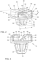
Figur 2 wird deutlich, dass die Aufnahme 20 von seitlichen Begrenzungswänden 44, Rückwänden 46 sowie oberen Abschlusswänden 48 gebildet wird. Die Begrenzungswände 44, Rückwände 46 und Abschlusswände 48 sind einstückig mit dem Befestigungselement 10 ausgebildet. - Hierdurch kommt es zur Ausbildung des Einschubbereiches 24 zwischen dem Grundkörper 16, den Begrenzungswänden 44, Rückwänden 46 und den Abschlusswänden 48.
- Zwischen den Rückwänden 46 und den Abschlusswänden 48 ist ein durchgehender Spalt 50 ausgebildet.
- Auf der dem Einschubbereich 24 zugewandten Seite des Grundkörpers 16 ist eine Auflagefläche 52 ausgebildet, die über eine Rampe 54 in eine vordere Abschlusskante 56 des Grundkörpers 16 übergeht. In Richtung der Rückwände 46 geht die Auflagefläche 52 über eine Stufe 58 der Auflagefläche 52 auf die Oberseite des Grundkörpers 16 über. Die Rampe 54 und die Auflagefläche 52 sind im Bereich des Spaltes 50 angeordnet.
- Die Abschlusswände 48 bilden an ihren dem Spalt 50 und dem Einschubbereich 24 zugewandten Längskanten Anlageflächen 60 aus. Zwischen der Auflagefläche 52 und den Anlageflächen 60 besteht ein Abstand a.
- Die seitlichen Begrenzungswände 44 bilden Anschlagflächen 62 aus. Die Innenseiten der Begrenzungswände 44 sind in einem Abstand b voneinander angeordnet.
- Zwischen der Innenseite der Rückwände 46 und den Anschlagflächen 62 besitzt der Einschubbereich eine Tiefe t.
- In den
Figuren 3 und4 ist das Befestigungselement 10 aus verschiedenen Perspektiven gezeigt, wobei gleiche Teile wiederum mit gleichem Bezugszeichen versehen und nicht nochmals zu erläutert sind. - Insbesondere in
Figur 4 wird deutlich, wie die Auflagefläche 52 in die Stufe 58 übergeht. Auch wird die Ausbildung des Spaltes 50 zwischen den Rückwänden 46 und den Abschlusswänden 48 deutlich. Der Spalt 50 kann im Bereich der Rückwände 46 auch geschlossen sein. Hierdurch erhöht sich eine Steifigkeit des Befestigungselementes 10 und eine Größe der erforderlichen Demontagekraft ist beeinflussbar. - In
Figur 5 ist in einer schematischen Perspektivansicht der Abschnitt 26 des zweiten Bauelementes 14 dargestellt. - Es wird deutlich, dass der Abschnitt 26 einen Führungsbereich 64 und einen Arretierungsbereich 66 aufweist. Der Arretierungsbereich 66 besitzt seitliche Führungsflächen 68 sowie eine obere Anlagefläche 70 und eine untere Anlagefläche 72. Der Abstand der Anlageflächen 70 und 72 zueinander bestimmt eine Höhe h des Arretierungsbereiches 66.
- Die Führungsflächen 68 gehen an einer ersten Stirnfläche 74 über Auflaufflächen 76 in die Stirnfläche 74 über. Das heißt, der Arretierungsbereich 66 verjüngt sich in Richtung der Stirnfläche 74.
- An der der Stirnfläche 74 gegenüberliegenden Stirnfläche 78 des Arretierungsbereiches 66 sind Anschlagflächen 80 ausgebildet.
- Von einer Unterseite 82 des Arretierungsbereiches 66 erstreckt sich ein nasenartiger Vorsprung 84, der in Richtung der Stirnfläche 78 über eine Stufe 86 des Vorsprungs 84 und in Richtung der Stirnfläche 74 über eine Schräge 88 in die Unterseite 82 und somit in die Anlagefläche 72 übergeht.
- Das Zusammenwirken des Abschnittes 26 des zweiten Bauelementes 14 mit der Aufnahme 20 des Befestigungselementes 10 wird anhand der
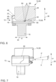
Figur 6 näher erläutert.Figur 6 zeigt eine Schnittdarstellung durch ein mittels des Befestigungselementes 10 fixiertes zweites Bauelement 14. - Der Abschnitt 26 wird mit seinem Führungsbereich 64 in den Spalt 50 der Aufnahme 20 in der zweiten Montagerichtung X eingeschoben. Die Führungsflächen 68 des Arretierungsbereiches 66 gelangen hierbei in Anlagekontakt mit den seitlichen Begrenzungswänden 44. Der Abstand b der Begrenzungswände 44 entspricht hierbei der Breite des Arretierungsbereiches 66, so dass ein definiertes Einschieben des Abschnittes 26 in die Aufnahme 20 in der zweiten Montagerichtung X möglich ist. Gleichzeitig ergibt sich hierdurch eine Positionierung des zweiten Bauelementes 14 in der dritten Montagerichtung Z. Diese läuft in der Ansicht in
Figur 6 in die Papierebene hinein. - Die Höhe h des Arretierungsbereiches 66 ist geringfügig größer als der Abstand a der Auflagefläche 52 zu den Anlageflächen 60. Hierdurch wird erreicht, dass beim Einschieben des Abschnittes 26 in die Aufnahme 20 die oberen Abschlusswände 48 des Befestigungselementes 10 geringfügig in der ersten Montagerichtung Y verdrängt werden.
- Der Abschnitt 26 wird so weit in die Aufnahme 20 eingeschoben, bis die Stufe 86 des Vorsprunges 84 mit der Stufe 58 der Auflagefläche 52 verrastet. In dieser Position drängen die oberen Abschlussflächen 48 mit ihren Anlageflächen 60 aufgrund der dem Material des Befestigungselementes 10 innewohnenden Elastizität in Richtung der Anlagefläche 70 des Arretierungsbereiches 66. Der Abschnitt 26 und somit das zweite Bauelement 14 ist somit sicher in der ersten Montagerichtung Y fixiert.
- In dem Moment, wo die Stufe 86 des Vorsprunges 84 die Stufe 58 der Auflagefläche 52 hinterrastet, schlägt die Anschlagfläche 80 des Arretierungsbereiches 66 an die Anschlagflächen 62 der Aufnahme 20 an. Der Abschnitt 26 und somit das zweite Bauelement 14 ist sicher in der zweiten Montagerichtung X fixiert. Es wird eine definierte Position des zweiten Bauelementes 14 in Bezug auf das Befestigungselement 10 und somit über dieses auch in Bezug auf das erste Bauelement 12 eingenommen.
- Wie in der Schnittdarstellung in
Figur 6 zu entnehmen ist, verlaufen die Stufen 86 und 58 unter einem Winkel β zur ersten Montagerichtung Y. Die Größe des Winkels β bestimmt die Haltekraft des Befestigungselementes 10 in Bezug auf das zweite Bauelement 14. Je kleiner der Winkel β, umso höher die Haltekraft. Der Winkel β beträgt beispielsweise 1 - 3 °. - In
Figur 7 ist ein mit dem Befestigungselement 10 montiertes zweites Bauelement 14 gezeigt. Die Einzelheiten sind in derFigur 7 nicht mit Bezugszeichen versehen, da diese anhand der vorherigen Figuren bereits nachvollziehbar sind. - Anhand der
Figur 7 wird verdeutlicht, dass das zweite Bauelement 14 in der zweiten Montagerichtung X in das Befestigungselement 10 eingeschoben wird. Hierbei werden die Abschlusswände 48 mit den Anlagenflächen 60 elastisch federnd leicht aufgebogen. - Zwischen dem zweiten Bauelement 14 und dem Befestigungselement 10 besteht eine lösbare Fixierung.
- Zum Lösen, das heißt Demontieren des zweiten Bauelementes 14 aus dem Befestigungselement 10, wird dieses um einen Demontagewinkel α in der ersten Montagerichtung Y verschwenkt. Hierbei muss die Haltekraft, die durch den Winkel β bestimmt wird, überwunden werden. Das zweite Bauelement 14 wird soweit in der ersten Montagerichtung Y verschwenkt, bis die Stufen 86 und 58 außer Eingriff gelangen. Sobald dies erfolgt ist, kann das zweite Bauelement 14 in der Demontagerichtung X' aus der Aufnahme 20 des Befestigungselementes 10 herausgeführt werden.
- Der Demontagewinkel α bestimmt die Demontagekraft. Je größer der Winkel α ist, umso kleiner wirkt die Demontagekraft.
- Bei dem zweiten Bauelement 14 kann es sich beispielsweise um eine Fahrzeugleuchte 94, insbesondere eine Rückleuchte eines Fahrzeuges 90, handeln. Bei dem ersten Bauelement 12 handelt es sich beispielsweise um einen Karosserieabschnitt einer Fahrzeugkarosserie 92.
- In
Figur 8 ist hierzu ein Fahrzeug 90 gezeigt. An einer Fahrzeugkarosserie 92 ist eine Fahrzeugleuchte 94 (hier eine Rückleuchte) angeordnet. - Durch das Befestigungselement 10 wird somit eine lösbare Fixierung der Fahrzeugleuchte 94 bei gleichzeitiger definierter Ausrichtung in X-Richtung, Y-Richtung und Z-Richtung an der Fahrzeugkarosserie 92 möglich. Somit können Spaltbildungen zwischen der Fahrzeugleuchte 94 und der Fahrzeugkarosserie 92 verhindert beziehungsweise minimiert werden. Durch Vorsehen des Dichtungselementes 30, über das das Befestigungselement 10 am ersten Bauelement 12, also beispielsweise der Fahrzeugkarosserie 92 anliegt, kann auch eine dichte Anordnung der Fahrzeugleuchte 94 an der Fahrzeugkarosserie 92 realisiert werden.
-
- 10
- Befestigungselement
- 12
- erstes Bauelement
- 14
- zweites Bauelement
- 16
- Grundkörper
- 18
- Rastelement
- 20
- Aufnahme
- 22
- Öffnung
- 24
- Einschubbereich
- 26
- Abschnitt
- 28
- Federschenkel
- 30
- Dichtungselement
- 32
- Öffnung
- 34
- Oberseite
- 36
- Unterseite
- 38
- Doppelpfeil
- 40
- Doppelpfeil
- 42
- Doppelpfeil
- 44
- Begrenzungswände
- 46
- Rückwände
- 48
- Abschlusswände
- 50
- Spalt
- 52
- Auflagefläche
- 54
- Rampe
- 56
- Abschlusskante
- 58
- Stufe
- 60
- Anlagefläche
- 62
- Anschlagflächen
- 64
- Führungsbereich
- 66
- Arretierungsbereich
- 68
- Führungsfläche
- 70
- Anlagefläche
- 72
- Anlagefläche
- 74
- Stirnfläche
- 76
- Auflauffläche
- 78
- Stirnfläche
- 80
- Anschlagfläche
- 82
- Unterseite
- 84
- Vorsprung
- 86
- Stufe
- 88
- Schräge
- 90
- Fahrzeug
- 92
- Fahrzeugkarosserie
- 94
- Fahrzeugleuchte
- a
- Abstand
- b
- Abstand
- h
- Höhe
- t
- Tiefe
- α
- Demontagewinkel
- β
- Winkel
- X
- zweite Montagerichtung
- Y
- erste Montagerichtung
- Z
- dritte Montagerichtung
- X'
- Demontagerichtung
Claims (9)
- Anordnung eines Befestigungselementes (10) zum lösbaren Verbinden von zwei Bauelementen (12, 14), welches einen Grundkörper (16) umfasst, der zumindest ein Rastelement (18) zum Verbinden mit einem ersten Bauelement (12) aufweist, wobei das Rastelement (18) in eine korrespondierende Öffnung (22) des ersten Bauelementes (12) in einer ersten Montagerichtung (Y) einbringbar ist, wobei der Grundkörper (16) an seiner dem Rastelement (18) gegenüberliegenden Seite eine Aufnahme (20) für zumindest einen Abschnitt (26) eines zweiten Bauelementes (14) aufweist, wobei die Aufnahme (20) und der Abschnitt (26) korrespondierende Formmerkmale aufweisen, die eine Führung des zweiten Bauelementes (14) in der ersten Montagerichtung (Y), in einer zweiten Montagerichtung (X) und einer dritten Montagerichtung (Z) übernehmen und die Aufnahme (20) und das zweite Bauelement (14) korrespondierende Rastmittel aufweisen, die einer lösbaren Fixierung des zweiten Bauelementes (14) in der zweiten Montagerichtung (X) dienen, wobei die Aufnahme (20) einen Einschubbereich (24) für den Abschnitt (26) des zweiten Bauelementes (14) in der Montagerichtung (X) ausbildet, dadurch gekennzeichnet, dass• auf der dem Einschubbereich (24) zugewandten Seite des Grundkörpers (16) eine Auflagefläche (52) ausgebildet ist, die über eine Rampe (54) in eine vordere Abschlusskante (56) des Grundkörpers (16) übergeht, wobei die Rampe (54) und die Auflagefläche (52) im Bereich eines Spaltes (50) angeordnet sind, der durch Rückwände (46) und obere Abschlusswände (48) des Befestigungselements (10) zur Aufnahme eines Führungsbereiches (64) des Abschnittes (26) des zweiten Bauelementes (14) gebildet ist,• wobei eine Stufe (86) eines Vorsprunges (84) des zweiten Bauelementes (14) im Zusammenwirken des Abschnittes (26) des zweiten Bauelementes (14) mit der Aufnahme (20) des Befestigungselementes (10) eine Stufe (58) der Auflagefläche (52) des Grundkörpers (16) hinterrastet und eine Anschlagfläche (80) eines Arretierungsbereiches (66) des Abschnittes (26) an Anschlagflächen (62) der Aufnahme (20) anschlägt.
- Anordnung nach Anspruch 1, dadurch gekennzeichnet, dass der Einschubbereich (24) von seitlichen Begrenzungswänden (44), den Rückwänden (46) und den oberen Abschlusswänden (48) gebildet ist.
- Anordnung nach Anspruch 2, dadurch gekennzeichnet, dass innerhalb des Einschubbereiches (24) die Auflagefläche (52) und Anlageflächen (60) für Anlageflächen (70, 72) des Arretierungsbereiches (66) des Abschnittes (26) ausgebildet sind.
- Anordnung nach Anspruch 3, dadurch gekennzeichnet, dass ein Abstand (a) zwischen der Auflagefläche (52) und den Anlageflächen (60) kleiner ist als eine Höhe (h) des Arretierungsbereiches (66).
- Anordnung nach den Ansprüchen 3 und 4, dadurch gekennzeichnet, dass der Arretierungsbereich (66) an seiner der Auflagefläche (52) zugeordneten Anlagefläche (72) einen Vorsprung (84) aufweist, der über die Stufe (86) in die Anlagefläche (72) übergeht.
- Anordnung nach Anspruch 1, dadurch gekennzeichnet, dass die Stufen (58, 86) unter einem Winkel (β) zur ersten Montagerichtung (Y) verlaufen.
- Anordnung nach Anspruch 1, dadurch gekennzeichnet, dass die Anschlagfläche (80) des Arretierungsbereiches (66) an die Anschlagflächen (62) der Aufnahme (20) anschlägt, wenn die Stufe (86) des Vorsprunges (84) des zweiten Bauelementes (14) im Zusammenwirken des Abschnittes (26) des zweiten Bauelementes (14) mit der Aufnahme (20) des Befestigungselementes (10) die Stufe (58) der Auflagefläche (52) hinterrastet.
- Anordnung nach einem der Ansprüche 1 bis 7, dadurch gekennzeichnet,
dass die oberen Abschlusswände (48) des Befestigungselementes (10) elastisch ausgebildet sind, wobei das zweite Bauelement (14) zur Demontage in Demontagerichtung (X`) aus dem Befestigungselement (10) um einen Demontagewinkel (α) in der ersten Montagerichtung (Y) unter Überwindung der Haltekraft, die durch einen Winkel (ß) zwischen den Stufen (58, 86) und der ersten Montagerichtung (Y) bestimmt wird, verschwenkbar ist, da die oberen Abschlusswände (48) elastisch ausgebildet sind. - Anordnung nach Anspruch 1, dadurch gekennzeichnet, dass das erste Bauelement (12) ein Karosserieabschnitt einer Fahrzeugkarosserie (92) und das zweite Bauelement (14) eine Fahrzeugleuchte (94) ist.
Applications Claiming Priority (2)
| Application Number | Priority Date | Filing Date | Title |
|---|---|---|---|
| DE102017121449.6A DE102017121449A1 (de) | 2017-09-15 | 2017-09-15 | Befestigungselement zum lösbaren Verbinden von zwei Bauelementen |
| PCT/EP2018/074879 WO2019053189A1 (de) | 2017-09-15 | 2018-09-14 | Befestigungselement zum lösbaren verbinden von zwei bauelementen |
Publications (2)
| Publication Number | Publication Date |
|---|---|
| EP3682127A1 EP3682127A1 (de) | 2020-07-22 |
| EP3682127B1 true EP3682127B1 (de) | 2023-11-01 |
Family
ID=63592733
Family Applications (1)
| Application Number | Title | Priority Date | Filing Date |
|---|---|---|---|
| EP18770003.4A Active EP3682127B1 (de) | 2017-09-15 | 2018-09-14 | Anordnung mit befestigungselement zum lösbaren verbinden von zwei bauelementen |
Country Status (4)
| Country | Link |
|---|---|
| EP (1) | EP3682127B1 (de) |
| CN (1) | CN111247349B (de) |
| DE (1) | DE102017121449A1 (de) |
| WO (1) | WO2019053189A1 (de) |
Families Citing this family (4)
| Publication number | Priority date | Publication date | Assignee | Title |
|---|---|---|---|---|
| DE102020120767A1 (de) * | 2020-08-06 | 2022-02-10 | Phoenix Contact Gmbh & Co. Kg | Tragschienenbefestigungseinrichtung, Verfahren, Anordnung und Schaltschrank |
| DE102020120765A1 (de) * | 2020-08-06 | 2022-02-10 | Phoenix Contact Gmbh & Co. Kg | Tragschienenbefestigungseinrichtung, Verfahren, Anordnung und Schaltschrank |
| DE102021122129A1 (de) * | 2020-10-16 | 2022-04-21 | Illinois Tool Works Inc. | Befestigungsvorrichtung |
| DE102024002111A1 (de) | 2024-06-27 | 2025-12-31 | Mercedes-Benz Group AG | Fügehilfseinrichtung |
Family Cites Families (15)
| Publication number | Priority date | Publication date | Assignee | Title |
|---|---|---|---|---|
| JPS60203547A (ja) * | 1984-03-28 | 1985-10-15 | Toyoda Gosei Co Ltd | 合成樹脂製取付部材の取着部材組付構造 |
| JP3148787B2 (ja) * | 1993-01-25 | 2001-03-26 | 東海興業株式会社 | 自動車用サイドプロテクターモール |
| JP3684255B2 (ja) * | 1995-07-28 | 2005-08-17 | 株式会社パイオラックス | 部品の取付構造 |
| FR2780115B1 (fr) * | 1998-06-23 | 2000-08-25 | Eurostyle Sa | Agrafe de fixation |
| CA2358824C (en) * | 2000-10-13 | 2005-06-28 | Hashimoto Forming Industry Company Limited | Automobile molding and fastener therefor |
| US6406242B1 (en) | 2000-11-10 | 2002-06-18 | Trw Inc. | Apparatus for fastening together two plates |
| US6715185B2 (en) * | 2002-07-25 | 2004-04-06 | Illinois Tool Works Inc. | Self aligning panel fastener |
| US6994504B2 (en) | 2003-06-24 | 2006-02-07 | Trw Automotive U.S. | Two part slide fastener |
| FR2938024B1 (fr) * | 2008-11-04 | 2013-04-12 | Trw Automotive Electron & Comp | Clip de fixation |
| JP5399936B2 (ja) * | 2010-02-03 | 2014-01-29 | 大和化成工業株式会社 | クリップ取付け構造 |
| JP5888615B2 (ja) * | 2013-12-17 | 2016-03-22 | ポップリベット・ファスナー株式会社 | 取付部材の取付構造 |
| CN204692265U (zh) * | 2015-04-29 | 2015-10-07 | 上海通用汽车有限公司 | 用于汽车门饰板的卡扣及包括其的汽车门饰板 |
| CN204729431U (zh) * | 2015-06-11 | 2015-10-28 | 福耀玻璃工业集团股份有限公司 | 一种带ω型嵌件的塑料钉柱 |
| TWI564623B (zh) * | 2015-10-08 | 2017-01-01 | 友達光電股份有限公司 | 顯示裝置及其組裝方法 |
| CN205064470U (zh) * | 2015-10-20 | 2016-03-02 | 安徽江淮汽车股份有限公司 | 一种卡接结构 |
-
2017
- 2017-09-15 DE DE102017121449.6A patent/DE102017121449A1/de not_active Withdrawn
-
2018
- 2018-09-14 EP EP18770003.4A patent/EP3682127B1/de active Active
- 2018-09-14 CN CN201880059933.4A patent/CN111247349B/zh active Active
- 2018-09-14 WO PCT/EP2018/074879 patent/WO2019053189A1/de not_active Ceased
Also Published As
| Publication number | Publication date |
|---|---|
| EP3682127A1 (de) | 2020-07-22 |
| CN111247349A (zh) | 2020-06-05 |
| WO2019053189A1 (de) | 2019-03-21 |
| CN111247349B (zh) | 2022-05-24 |
| DE102017121449A1 (de) | 2019-03-21 |
Similar Documents
| Publication | Publication Date | Title |
|---|---|---|
| DE60205579T2 (de) | Selbsthaltende Nietverbindung | |
| EP3682127B1 (de) | Anordnung mit befestigungselement zum lösbaren verbinden von zwei bauelementen | |
| EP3291705B1 (de) | Möbel mit einem schubkasten und verfahren zum festlegen eines schubkastens | |
| DE2309396C3 (de) | Vorrichtung für Einsatzschraubenschlüssel zur lösbaren axialen Befestigung eines Steckschlüssels | |
| DE2166787B2 (de) | Messerscheide mit schaerfvorrichtung | |
| DE102015106852A1 (de) | Vorrichtung und Verfahren zum Festlegen eines Schubelementes | |
| DE102013111400A1 (de) | Befestigungsvorrichtung für zwei Befestigungszustände | |
| DE102014109547A1 (de) | Verbindungsmittel und Verfahren zum Festlegen eines Verbindungselements an oder in einem Bauteil | |
| DE112008002568T5 (de) | Stoßfängerbefestigungsclip | |
| DE102015109997A1 (de) | Halterung | |
| DE102014112258A1 (de) | Clipsystem | |
| DE4129299C2 (de) | Befestigungsorgan für Heizkörper | |
| DE3902399A1 (de) | Zierleistenhalter | |
| DE2830384B2 (de) | Reiterschiene für Schreibmaschinen | |
| DE2932716A1 (de) | Wechselbildhalterung | |
| DE19524831C2 (de) | Haltevorrichtung für eine Kopfstütze an einem Fahrzeugsitz | |
| WO2020156726A1 (de) | Verfahren zum entfernen eines strahlreglers aus einem armaturenauslauf, strahlregler, verwendung einer strahlregleraufnahme und satz aus einem strahlregler und einem werkzeug | |
| DE19840642C2 (de) | Befestigungselement für einen Betätigungszug | |
| EP3189749A1 (de) | Ausziehführung für ein bewegbares möbelteil | |
| EP3025938B1 (de) | Abdeckvorrichtung für eine flächenseite eines wandelements | |
| DE29603389U1 (de) | Schnellverschluß | |
| DE3409732C2 (de) | Einbau-Aschenbecher für Kraftfahrzeuge | |
| DE19844095C1 (de) | Anschlußleiste für die Telekommunikationstechnik | |
| DE102021108249A1 (de) | Koppelelement, Schließsystem und Möbel | |
| EP3325744B1 (de) | Verfahren zur demontage einer führungsanordnung für eine schiebetür |
Legal Events
| Date | Code | Title | Description |
|---|---|---|---|
| STAA | Information on the status of an ep patent application or granted ep patent |
Free format text: STATUS: UNKNOWN |
|
| STAA | Information on the status of an ep patent application or granted ep patent |
Free format text: STATUS: THE INTERNATIONAL PUBLICATION HAS BEEN MADE |
|
| PUAI | Public reference made under article 153(3) epc to a published international application that has entered the european phase |
Free format text: ORIGINAL CODE: 0009012 |
|
| STAA | Information on the status of an ep patent application or granted ep patent |
Free format text: STATUS: REQUEST FOR EXAMINATION WAS MADE |
|
| 17P | Request for examination filed |
Effective date: 20200414 |
|
| AK | Designated contracting states |
Kind code of ref document: A1 Designated state(s): AL AT BE BG CH CY CZ DE DK EE ES FI FR GB GR HR HU IE IS IT LI LT LU LV MC MK MT NL NO PL PT RO RS SE SI SK SM TR |
|
| AX | Request for extension of the european patent |
Extension state: BA ME |
|
| DAV | Request for validation of the european patent (deleted) | ||
| DAX | Request for extension of the european patent (deleted) | ||
| STAA | Information on the status of an ep patent application or granted ep patent |
Free format text: STATUS: EXAMINATION IS IN PROGRESS |
|
| RIC1 | Information provided on ipc code assigned before grant |
Ipc: F16B 5/06 20060101ALI20220909BHEP Ipc: B60Q 1/26 20060101ALI20220909BHEP Ipc: F16B 21/08 20060101AFI20220909BHEP |
|
| 17Q | First examination report despatched |
Effective date: 20221004 |
|
| GRAP | Despatch of communication of intention to grant a patent |
Free format text: ORIGINAL CODE: EPIDOSNIGR1 |
|
| STAA | Information on the status of an ep patent application or granted ep patent |
Free format text: STATUS: GRANT OF PATENT IS INTENDED |
|
| INTG | Intention to grant announced |
Effective date: 20230531 |
|
| GRAS | Grant fee paid |
Free format text: ORIGINAL CODE: EPIDOSNIGR3 |
|
| GRAA | (expected) grant |
Free format text: ORIGINAL CODE: 0009210 |
|
| STAA | Information on the status of an ep patent application or granted ep patent |
Free format text: STATUS: THE PATENT HAS BEEN GRANTED |
|
| AK | Designated contracting states |
Kind code of ref document: B1 Designated state(s): AL AT BE BG CH CY CZ DE DK EE ES FI FR GB GR HR HU IE IS IT LI LT LU LV MC MK MT NL NO PL PT RO RS SE SI SK SM TR |
|
| REG | Reference to a national code |
Ref country code: GB Ref legal event code: FG4D Free format text: NOT ENGLISH |
|
| REG | Reference to a national code |
Ref country code: CH Ref legal event code: EP |
|
| REG | Reference to a national code |
Ref country code: DE Ref legal event code: R096 Ref document number: 502018013574 Country of ref document: DE |
|
| REG | Reference to a national code |
Ref country code: IE Ref legal event code: FG4D Free format text: LANGUAGE OF EP DOCUMENT: GERMAN |
|
| P01 | Opt-out of the competence of the unified patent court (upc) registered |
Effective date: 20231030 |
|
| REG | Reference to a national code |
Ref country code: LT Ref legal event code: MG9D |
|
| REG | Reference to a national code |
Ref country code: NL Ref legal event code: MP Effective date: 20231101 |
|
| PG25 | Lapsed in a contracting state [announced via postgrant information from national office to epo] |
Ref country code: GR Free format text: LAPSE BECAUSE OF FAILURE TO SUBMIT A TRANSLATION OF THE DESCRIPTION OR TO PAY THE FEE WITHIN THE PRESCRIBED TIME-LIMIT Effective date: 20240202 |
|
| PG25 | Lapsed in a contracting state [announced via postgrant information from national office to epo] |
Ref country code: IS Free format text: LAPSE BECAUSE OF FAILURE TO SUBMIT A TRANSLATION OF THE DESCRIPTION OR TO PAY THE FEE WITHIN THE PRESCRIBED TIME-LIMIT Effective date: 20240301 |
|
| PG25 | Lapsed in a contracting state [announced via postgrant information from national office to epo] |
Ref country code: LT Free format text: LAPSE BECAUSE OF FAILURE TO SUBMIT A TRANSLATION OF THE DESCRIPTION OR TO PAY THE FEE WITHIN THE PRESCRIBED TIME-LIMIT Effective date: 20231101 |
|
| PG25 | Lapsed in a contracting state [announced via postgrant information from national office to epo] |
Ref country code: NL Free format text: LAPSE BECAUSE OF FAILURE TO SUBMIT A TRANSLATION OF THE DESCRIPTION OR TO PAY THE FEE WITHIN THE PRESCRIBED TIME-LIMIT Effective date: 20231101 |
|
| PG25 | Lapsed in a contracting state [announced via postgrant information from national office to epo] |
Ref country code: ES Free format text: LAPSE BECAUSE OF FAILURE TO SUBMIT A TRANSLATION OF THE DESCRIPTION OR TO PAY THE FEE WITHIN THE PRESCRIBED TIME-LIMIT Effective date: 20231101 |
|
| PG25 | Lapsed in a contracting state [announced via postgrant information from national office to epo] |
Ref country code: NL Free format text: LAPSE BECAUSE OF FAILURE TO SUBMIT A TRANSLATION OF THE DESCRIPTION OR TO PAY THE FEE WITHIN THE PRESCRIBED TIME-LIMIT Effective date: 20231101 Ref country code: LT Free format text: LAPSE BECAUSE OF FAILURE TO SUBMIT A TRANSLATION OF THE DESCRIPTION OR TO PAY THE FEE WITHIN THE PRESCRIBED TIME-LIMIT Effective date: 20231101 Ref country code: IS Free format text: LAPSE BECAUSE OF FAILURE TO SUBMIT A TRANSLATION OF THE DESCRIPTION OR TO PAY THE FEE WITHIN THE PRESCRIBED TIME-LIMIT Effective date: 20240301 Ref country code: GR Free format text: LAPSE BECAUSE OF FAILURE TO SUBMIT A TRANSLATION OF THE DESCRIPTION OR TO PAY THE FEE WITHIN THE PRESCRIBED TIME-LIMIT Effective date: 20240202 Ref country code: ES Free format text: LAPSE BECAUSE OF FAILURE TO SUBMIT A TRANSLATION OF THE DESCRIPTION OR TO PAY THE FEE WITHIN THE PRESCRIBED TIME-LIMIT Effective date: 20231101 Ref country code: BG Free format text: LAPSE BECAUSE OF FAILURE TO SUBMIT A TRANSLATION OF THE DESCRIPTION OR TO PAY THE FEE WITHIN THE PRESCRIBED TIME-LIMIT Effective date: 20240201 Ref country code: PT Free format text: LAPSE BECAUSE OF FAILURE TO SUBMIT A TRANSLATION OF THE DESCRIPTION OR TO PAY THE FEE WITHIN THE PRESCRIBED TIME-LIMIT Effective date: 20240301 |
|
| PG25 | Lapsed in a contracting state [announced via postgrant information from national office to epo] |
Ref country code: SE Free format text: LAPSE BECAUSE OF FAILURE TO SUBMIT A TRANSLATION OF THE DESCRIPTION OR TO PAY THE FEE WITHIN THE PRESCRIBED TIME-LIMIT Effective date: 20231101 Ref country code: RS Free format text: LAPSE BECAUSE OF FAILURE TO SUBMIT A TRANSLATION OF THE DESCRIPTION OR TO PAY THE FEE WITHIN THE PRESCRIBED TIME-LIMIT Effective date: 20231101 Ref country code: PL Free format text: LAPSE BECAUSE OF FAILURE TO SUBMIT A TRANSLATION OF THE DESCRIPTION OR TO PAY THE FEE WITHIN THE PRESCRIBED TIME-LIMIT Effective date: 20231101 Ref country code: NO Free format text: LAPSE BECAUSE OF FAILURE TO SUBMIT A TRANSLATION OF THE DESCRIPTION OR TO PAY THE FEE WITHIN THE PRESCRIBED TIME-LIMIT Effective date: 20240201 Ref country code: LV Free format text: LAPSE BECAUSE OF FAILURE TO SUBMIT A TRANSLATION OF THE DESCRIPTION OR TO PAY THE FEE WITHIN THE PRESCRIBED TIME-LIMIT Effective date: 20231101 Ref country code: HR Free format text: LAPSE BECAUSE OF FAILURE TO SUBMIT A TRANSLATION OF THE DESCRIPTION OR TO PAY THE FEE WITHIN THE PRESCRIBED TIME-LIMIT Effective date: 20231101 |
|
| PG25 | Lapsed in a contracting state [announced via postgrant information from national office to epo] |
Ref country code: DK Free format text: LAPSE BECAUSE OF FAILURE TO SUBMIT A TRANSLATION OF THE DESCRIPTION OR TO PAY THE FEE WITHIN THE PRESCRIBED TIME-LIMIT Effective date: 20231101 |
|
| PG25 | Lapsed in a contracting state [announced via postgrant information from national office to epo] |
Ref country code: CZ Free format text: LAPSE BECAUSE OF FAILURE TO SUBMIT A TRANSLATION OF THE DESCRIPTION OR TO PAY THE FEE WITHIN THE PRESCRIBED TIME-LIMIT Effective date: 20231101 |
|
| PG25 | Lapsed in a contracting state [announced via postgrant information from national office to epo] |
Ref country code: SK Free format text: LAPSE BECAUSE OF FAILURE TO SUBMIT A TRANSLATION OF THE DESCRIPTION OR TO PAY THE FEE WITHIN THE PRESCRIBED TIME-LIMIT Effective date: 20231101 |
|
| PG25 | Lapsed in a contracting state [announced via postgrant information from national office to epo] |
Ref country code: SM Free format text: LAPSE BECAUSE OF FAILURE TO SUBMIT A TRANSLATION OF THE DESCRIPTION OR TO PAY THE FEE WITHIN THE PRESCRIBED TIME-LIMIT Effective date: 20231101 Ref country code: SK Free format text: LAPSE BECAUSE OF FAILURE TO SUBMIT A TRANSLATION OF THE DESCRIPTION OR TO PAY THE FEE WITHIN THE PRESCRIBED TIME-LIMIT Effective date: 20231101 Ref country code: IT Free format text: LAPSE BECAUSE OF FAILURE TO SUBMIT A TRANSLATION OF THE DESCRIPTION OR TO PAY THE FEE WITHIN THE PRESCRIBED TIME-LIMIT Effective date: 20231101 Ref country code: EE Free format text: LAPSE BECAUSE OF FAILURE TO SUBMIT A TRANSLATION OF THE DESCRIPTION OR TO PAY THE FEE WITHIN THE PRESCRIBED TIME-LIMIT Effective date: 20231101 Ref country code: DK Free format text: LAPSE BECAUSE OF FAILURE TO SUBMIT A TRANSLATION OF THE DESCRIPTION OR TO PAY THE FEE WITHIN THE PRESCRIBED TIME-LIMIT Effective date: 20231101 Ref country code: CZ Free format text: LAPSE BECAUSE OF FAILURE TO SUBMIT A TRANSLATION OF THE DESCRIPTION OR TO PAY THE FEE WITHIN THE PRESCRIBED TIME-LIMIT Effective date: 20231101 |
|
| REG | Reference to a national code |
Ref country code: DE Ref legal event code: R097 Ref document number: 502018013574 Country of ref document: DE |
|
| PLBE | No opposition filed within time limit |
Free format text: ORIGINAL CODE: 0009261 |
|
| STAA | Information on the status of an ep patent application or granted ep patent |
Free format text: STATUS: NO OPPOSITION FILED WITHIN TIME LIMIT |
|
| 26N | No opposition filed |
Effective date: 20240802 |
|
| PG25 | Lapsed in a contracting state [announced via postgrant information from national office to epo] |
Ref country code: SI Free format text: LAPSE BECAUSE OF FAILURE TO SUBMIT A TRANSLATION OF THE DESCRIPTION OR TO PAY THE FEE WITHIN THE PRESCRIBED TIME-LIMIT Effective date: 20231101 |
|
| PG25 | Lapsed in a contracting state [announced via postgrant information from national office to epo] |
Ref country code: SI Free format text: LAPSE BECAUSE OF FAILURE TO SUBMIT A TRANSLATION OF THE DESCRIPTION OR TO PAY THE FEE WITHIN THE PRESCRIBED TIME-LIMIT Effective date: 20231101 |
|
| PG25 | Lapsed in a contracting state [announced via postgrant information from national office to epo] |
Ref country code: MC Free format text: LAPSE BECAUSE OF FAILURE TO SUBMIT A TRANSLATION OF THE DESCRIPTION OR TO PAY THE FEE WITHIN THE PRESCRIBED TIME-LIMIT Effective date: 20231101 |
|
| REG | Reference to a national code |
Ref country code: CH Ref legal event code: PL |
|
| PG25 | Lapsed in a contracting state [announced via postgrant information from national office to epo] |
Ref country code: LU Free format text: LAPSE BECAUSE OF NON-PAYMENT OF DUE FEES Effective date: 20240914 |
|
| GBPC | Gb: european patent ceased through non-payment of renewal fee |
Effective date: 20240914 |
|
| PG25 | Lapsed in a contracting state [announced via postgrant information from national office to epo] |
Ref country code: GB Free format text: LAPSE BECAUSE OF NON-PAYMENT OF DUE FEES Effective date: 20240914 |
|
| REG | Reference to a national code |
Ref country code: BE Ref legal event code: MM Effective date: 20240930 |
|
| PG25 | Lapsed in a contracting state [announced via postgrant information from national office to epo] |
Ref country code: BE Free format text: LAPSE BECAUSE OF NON-PAYMENT OF DUE FEES Effective date: 20240930 |
|
| PG25 | Lapsed in a contracting state [announced via postgrant information from national office to epo] |
Ref country code: CH Free format text: LAPSE BECAUSE OF NON-PAYMENT OF DUE FEES Effective date: 20240930 |
|
| PG25 | Lapsed in a contracting state [announced via postgrant information from national office to epo] |
Ref country code: IE Free format text: LAPSE BECAUSE OF NON-PAYMENT OF DUE FEES Effective date: 20240914 |
|
| PG25 | Lapsed in a contracting state [announced via postgrant information from national office to epo] |
Ref country code: FI Free format text: LAPSE BECAUSE OF FAILURE TO SUBMIT A TRANSLATION OF THE DESCRIPTION OR TO PAY THE FEE WITHIN THE PRESCRIBED TIME-LIMIT Effective date: 20231101 |
|
| PGFP | Annual fee paid to national office [announced via postgrant information from national office to epo] |
Ref country code: DE Payment date: 20250929 Year of fee payment: 8 |
|
| PGFP | Annual fee paid to national office [announced via postgrant information from national office to epo] |
Ref country code: FR Payment date: 20250924 Year of fee payment: 8 |
|
| REG | Reference to a national code |
Ref country code: AT Ref legal event code: MM01 Ref document number: 1627507 Country of ref document: AT Kind code of ref document: T Effective date: 20240914 |
|
| PG25 | Lapsed in a contracting state [announced via postgrant information from national office to epo] |
Ref country code: RO Free format text: LAPSE BECAUSE OF FAILURE TO SUBMIT A TRANSLATION OF THE DESCRIPTION OR TO PAY THE FEE WITHIN THE PRESCRIBED TIME-LIMIT Effective date: 20231101 |
|
| PG25 | Lapsed in a contracting state [announced via postgrant information from national office to epo] |
Ref country code: AT Free format text: LAPSE BECAUSE OF NON-PAYMENT OF DUE FEES Effective date: 20240914 |
|
| PG25 | Lapsed in a contracting state [announced via postgrant information from national office to epo] |
Ref country code: CY Free format text: LAPSE BECAUSE OF FAILURE TO SUBMIT A TRANSLATION OF THE DESCRIPTION OR TO PAY THE FEE WITHIN THE PRESCRIBED TIME-LIMIT; INVALID AB INITIO Effective date: 20180914 |
|
| PG25 | Lapsed in a contracting state [announced via postgrant information from national office to epo] |
Ref country code: HU Free format text: LAPSE BECAUSE OF FAILURE TO SUBMIT A TRANSLATION OF THE DESCRIPTION OR TO PAY THE FEE WITHIN THE PRESCRIBED TIME-LIMIT; INVALID AB INITIO Effective date: 20180914 |