EP3660392A1 - Lampeneinheit und fahrzeugscheinwerfer - Google Patents
Lampeneinheit und fahrzeugscheinwerfer Download PDFInfo
- Publication number
- EP3660392A1 EP3660392A1 EP18838801.1A EP18838801A EP3660392A1 EP 3660392 A1 EP3660392 A1 EP 3660392A1 EP 18838801 A EP18838801 A EP 18838801A EP 3660392 A1 EP3660392 A1 EP 3660392A1
- Authority
- EP
- European Patent Office
- Prior art keywords
- distribution pattern
- light
- light distribution
- vehicle
- region
- Prior art date
- Legal status (The legal status is an assumption and is not a legal conclusion. Google has not performed a legal analysis and makes no representation as to the accuracy of the status listed.)
- Pending
Links
- 238000010586 diagram Methods 0.000 description 14
- 230000003287 optical effect Effects 0.000 description 8
- 238000000034 method Methods 0.000 description 5
- 230000004313 glare Effects 0.000 description 4
- 238000012986 modification Methods 0.000 description 3
- 230000004048 modification Effects 0.000 description 3
- 230000000694 effects Effects 0.000 description 2
- 230000035945 sensitivity Effects 0.000 description 2
- 238000003384 imaging method Methods 0.000 description 1
- 238000004519 manufacturing process Methods 0.000 description 1
- 230000003252 repetitive effect Effects 0.000 description 1
- 239000004065 semiconductor Substances 0.000 description 1
- 230000002194 synthesizing effect Effects 0.000 description 1
- 230000000007 visual effect Effects 0.000 description 1
Images


Classifications
-
- F—MECHANICAL ENGINEERING; LIGHTING; HEATING; WEAPONS; BLASTING
- F21—LIGHTING
- F21S—NON-PORTABLE LIGHTING DEVICES; SYSTEMS THEREOF; VEHICLE LIGHTING DEVICES SPECIALLY ADAPTED FOR VEHICLE EXTERIORS
- F21S41/00—Illuminating devices specially adapted for vehicle exteriors, e.g. headlamps
- F21S41/10—Illuminating devices specially adapted for vehicle exteriors, e.g. headlamps characterised by the light source
- F21S41/14—Illuminating devices specially adapted for vehicle exteriors, e.g. headlamps characterised by the light source characterised by the type of light source
- F21S41/141—Light emitting diodes [LED]
- F21S41/147—Light emitting diodes [LED] the main emission direction of the LED being angled to the optical axis of the illuminating device
- F21S41/148—Light emitting diodes [LED] the main emission direction of the LED being angled to the optical axis of the illuminating device the main emission direction of the LED being perpendicular to the optical axis
-
- F—MECHANICAL ENGINEERING; LIGHTING; HEATING; WEAPONS; BLASTING
- F21—LIGHTING
- F21S—NON-PORTABLE LIGHTING DEVICES; SYSTEMS THEREOF; VEHICLE LIGHTING DEVICES SPECIALLY ADAPTED FOR VEHICLE EXTERIORS
- F21S41/00—Illuminating devices specially adapted for vehicle exteriors, e.g. headlamps
- F21S41/60—Illuminating devices specially adapted for vehicle exteriors, e.g. headlamps characterised by a variable light distribution
- F21S41/67—Illuminating devices specially adapted for vehicle exteriors, e.g. headlamps characterised by a variable light distribution by acting on reflectors
- F21S41/675—Illuminating devices specially adapted for vehicle exteriors, e.g. headlamps characterised by a variable light distribution by acting on reflectors by moving reflectors
-
- F—MECHANICAL ENGINEERING; LIGHTING; HEATING; WEAPONS; BLASTING
- F21—LIGHTING
- F21S—NON-PORTABLE LIGHTING DEVICES; SYSTEMS THEREOF; VEHICLE LIGHTING DEVICES SPECIALLY ADAPTED FOR VEHICLE EXTERIORS
- F21S41/00—Illuminating devices specially adapted for vehicle exteriors, e.g. headlamps
- F21S41/10—Illuminating devices specially adapted for vehicle exteriors, e.g. headlamps characterised by the light source
- F21S41/12—Illuminating devices specially adapted for vehicle exteriors, e.g. headlamps characterised by the light source characterised by the type of emitted light
- F21S41/13—Ultraviolet light; Infrared light
-
- F—MECHANICAL ENGINEERING; LIGHTING; HEATING; WEAPONS; BLASTING
- F21—LIGHTING
- F21S—NON-PORTABLE LIGHTING DEVICES; SYSTEMS THEREOF; VEHICLE LIGHTING DEVICES SPECIALLY ADAPTED FOR VEHICLE EXTERIORS
- F21S41/00—Illuminating devices specially adapted for vehicle exteriors, e.g. headlamps
- F21S41/10—Illuminating devices specially adapted for vehicle exteriors, e.g. headlamps characterised by the light source
- F21S41/14—Illuminating devices specially adapted for vehicle exteriors, e.g. headlamps characterised by the light source characterised by the type of light source
- F21S41/141—Light emitting diodes [LED]
- F21S41/151—Light emitting diodes [LED] arranged in one or more lines
-
- F—MECHANICAL ENGINEERING; LIGHTING; HEATING; WEAPONS; BLASTING
- F21—LIGHTING
- F21S—NON-PORTABLE LIGHTING DEVICES; SYSTEMS THEREOF; VEHICLE LIGHTING DEVICES SPECIALLY ADAPTED FOR VEHICLE EXTERIORS
- F21S41/00—Illuminating devices specially adapted for vehicle exteriors, e.g. headlamps
- F21S41/60—Illuminating devices specially adapted for vehicle exteriors, e.g. headlamps characterised by a variable light distribution
- F21S41/62—Illuminating devices specially adapted for vehicle exteriors, e.g. headlamps characterised by a variable light distribution for adaptation between right-hand and left-hand traffic
Definitions
- the present invention relates to a lamp unit and a vehicular headlamp.
- Patent Literature 1 discloses an obstacle detecting device that includes: a light source including two LED units for emitting visible light, and an infrared light unit, provided between the two LED units, for emitting infrared light; and a rotating reflector that rotates about a rotational axis in one direction while reflecting visible light and infrared light emitted from the light source.
- Patent Literature 1 Japanese Unexamined Patent Application Publication No. 2012-224317
- the obstacle detecting device described above also functions as an optical unit in a headlamp; however, light distribution patterns produced respectively by the right headlamp and the left headlamp are substantially identical. Therefore, there is room for improvement in production of various light distribution patterns using visible light and infrared light.
- the present invention has been made in view of such a situation, and a purpose thereof is to provide a new optical unit capable of producing various light distribution patterns using infrared light and visible light.
- a lamp unit of one embodiment of the present invention is mounted on the right side or left side of a vehicle, and the lamp unit includes a light source including a first light emitting element that emits visible light and a second light emitting element that emits infrared light, and a rotating reflector that rotates about a rotational axis while reflecting visible light and infrared light emitted from the light source.
- the rotating reflector emits, by its rotating operation, visible light from the first light emitting element as an irradiation beam such that, by scanning with the irradiation beam, a first light distribution pattern is produced in front of the vehicle.
- the rotating reflector also emits, by its rotating operation, infrared light from the second light emitting element as an irradiation beam such that, by scanning with the irradiation beam, a second light distribution pattern is produced in front of the vehicle.
- the light source is configured such that part of the second light distribution pattern overlaps with the first light distribution pattern and such that a region of the second light distribution pattern, which does not overlap with the first light distribution pattern, is provided on the side closer to a middle region in front of the vehicle with respect to the first light distribution pattern.
- a region of the second light distribution pattern which does not overlap with the first light distribution pattern, i.e., the region only irradiated with infrared light by one lamp unit, can be provided on the side closer to a middle region in front of the vehicle with respect to the first light distribution pattern.
- a region of the second light distribution pattern which does not overlap with the first light distribution pattern, i.e., the region only irradiated with infrared light by one lamp unit, can also be provided on the side closer to the middle region in front of the vehicle with respect to the first light distribution pattern. Accordingly, such a region only irradiated with infrared light can be provided in a region relatively closer to the middle (a distant area) in front of the vehicle.
- the second light emitting element may be disposed such that the second light distribution pattern includes a vanishing point in front of the vehicle. Accordingly, when the first light distribution pattern is produced, for which the first light emitting element is turned on and off to provide a distant region in front of the vehicle as a non-illuminated region, the non-illuminated region can be irradiated with infrared light, for example.
- the first light emitting element may be disposed such that the first light distribution pattern includes a vanishing point in front of the vehicle.
- the light source may further include a third light emitting element that emits visible light.
- the rotating reflector may emit, by its rotating operation, visible light from the third light emitting element as an irradiation beam such that, by scanning with the irradiation beam, a third light distribution pattern is produced in front of the vehicle.
- the light source may be configured such that the third light distribution pattern overlaps with the first light distribution pattern and the second light distribution pattern and such that a region of the second light distribution pattern, which does not overlap with the third light distribution pattern, is provided on the side closer to a middle region in front of the vehicle with respect to the third light distribution pattern. Accordingly, the luminous intensity of the region where the third light distribution pattern overlaps with the first light distribution pattern can be increased.
- the vehicular headlamp includes a right lamp unit mounted on the right side of a vehicle and a left lamp unit mounted on the left side of the vehicle.
- the right lamp unit includes a first light source including a first light emitting element that emits visible light and a second light emitting element that emits infrared light, and a first rotating reflector that rotates about a rotational axis while reflecting visible light and infrared light emitted from the first light source.
- the first rotating reflector emits, by its rotating operation, visible light from the first light emitting element as an irradiation beam such that, by scanning with the irradiation beam, a first light distribution pattern is produced in front of the vehicle.
- the first rotating reflector also emits, by its rotating operation, infrared light from the second light emitting element as an irradiation beam such that, by scanning with the irradiation beam, a second light distribution pattern is produced in front of the vehicle.
- the first light source is configured such that part of the second light distribution pattern overlaps with the first light distribution pattern and such that a region of the second light distribution pattern, which does not overlap with the first light distribution pattern, is provided on the side closer to a middle region in front of the vehicle with respect to the first light distribution pattern.
- the left lamp unit includes a second light source including a third light emitting element that emits visible light and a fourth light emitting element that emits infrared light, and a second rotating reflector that rotates about a rotational axis while reflecting visible light and infrared light emitted from the second light source.
- the second rotating reflector emits, by its rotating operation, visible light from the third light emitting element as an irradiation beam such that, by scanning with the irradiation beam, a third light distribution pattern is produced in front of the vehicle.
- the second rotating reflector also emits, by its rotating operation, infrared light from the fourth light emitting element as an irradiation beam such that, by scanning with the irradiation beam, a fourth light distribution pattern is produced in front of the vehicle.
- the second light source is configured such that part of the fourth light distribution pattern overlaps with the third light distribution pattern and such that a region of the fourth light distribution pattern, which does not overlap with the third light distribution pattern, is provided on the side closer to a middle region in front of the vehicle with respect to the third light distribution pattern.
- the first light source and the second light source are configured such that a region of the second light distribution pattern, which does not overlap with the first light distribution pattern, overlaps with the third light distribution pattern and such that a region of the fourth light distribution pattern, which does not overlap with the third light distribution pattern, overlaps with the first light distribution pattern.
- a region of the second light distribution pattern which does not overlap with the first light distribution pattern, i.e., the region only irradiated with infrared light by the right lamp unit, can be provided on the side closer to a middle region in front of the vehicle with respect to the first light distribution pattern.
- a region of the fourth light distribution pattern which does not overlap with the third light distribution pattern, i.e., the region only irradiated with infrared light by the left lamp unit, can also be provided on the side closer to the middle region in front of the vehicle with respect to the third light distribution pattern.
- the present invention provides a new optical unit capable of producing various light distribution patterns using infrared light and visible light.
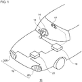
- FIG. 1 is a schematic diagram that shows an external view of a front part of a vehicle to which a vehicular headlamp of the present embodiment is applied.
- a vehicle 10 in the present embodiment includes a vehicular headlamp 12, a switch 16 provided near a steering wheel 14 and used to switch the lamp mode, a camera 17 for capturing an image of an area in front of the vehicle, and a vehicle controller 18 that processes information captured by the camera 17, information detected by a sensor, not illustrated, provided in the vehicle, and information of switching operations for the switch 16 performed by the driver, for example.
- the camera 17 is provided with an imaging element that at least has sensitivity to light with a wavelength within a range from a wavelength of visible light to a wavelength of infrared light, and the camera 17 transmits information of a captured image to the vehicle controller 18.
- the vehicular headlamp 12 includes a headlamp unit 20R mounted on the right side of a vehicle, and a headlamp unit 20L mounted on the left side of the vehicle. Based on the information transmitted from the vehicle controller 18, a headlamp controller 22 controls light irradiation, i.e., the shape and the position of a light distribution pattern provided by the headlamp unit 20R and the headlamp unit 20L.
- the headlamp controller 22 controls the headlamp units 20R and 20L based on the distance from a preceding vehicle travelling in front of the subject vehicle and the position of the preceding vehicle. In the present embodiment, when switching of the lamp mode using the switch 16 is performed, the headlamp controller 22 controls light irradiation by the headlamp units 20R and 20L appropriately for the selected lamp mode.
- the lamp modes selectable by means of the switch 16 include a “traveling mode (high beam mode)", a “passing mode (low beam mode)", and an “automatic adjustment mode (a shading high beam mode)", for example.
- the automatic adjustment mode is a mode in which a light distribution pattern is adjusted based on the distance from a preceding vehicle and the position of the preceding vehicle.
- the shading high beam mode is a mode for producing a shading high beam with which a partial region of a high beam light distribution pattern is not illuminated as appropriate, thereby reducing glare provided to a preceding vehicle present forward of the subject vehicle while improving visibility in a distant area.
- FIG. 2 is a horizontal sectional view of the headlamp unit 20R provided on the right side in the present embodiment.
- the headlamp unit 20R shown in FIG. 2 is a right headlamp mounted on the right side of a front end part of an automobile and has almost the same structure as a headlamp mounted on the left side, except that the headlamps have symmetrical structures. Accordingly, in the following, the headlamp unit 20 on the right side will be described in detail, and the description for the headlamp unit on the left side may be omitted as appropriate.
- the headlamp unit 20R includes a lamp body 24 having a recess part that opens on the front side.
- the opening on the front side of the lamp body 24 is covered with a transparent front cover 26, thereby forming a lamp chamber 28.
- the lamp chamber 28 serves as a space in which two lamp units 30 and 32 arranged in a vehicle width direction are housed.
- the lamp unit 32 disposed on the outer side of the vehicle i.e., the upper side in the right headlamp unit 20R shown in FIG. 2
- the lamp unit 30 disposed on the inner side of the vehicle i.e., the lower side in the right headlamp unit 20R shown in FIG. 2
- the lamp unit 30 for low beams includes a reflector 34, a light source bulb (an incandescent bulb) 36 supported by the reflector 34, and a shade, which is not illustrated, and the reflector 34 is supported by a known means, such as a means using an aiming screw and a nut, which is not illustrated, such as to be tilted with respect to the lamp body 24.
- the lamp unit 32 includes a rotating reflector 38, a light source 40 provided with an LED or the like that emits visible light or infrared light, and a convex lens 42 as a projection lens disposed forward of the rotating reflector 38.
- a semiconductor light emitting element such as an EL element and LD element, may be used for the light source 40.
- a light source of which turning on and off can be accurately performed in a short time is suitable.
- the shape of the convex lens 42 may be appropriately selected based on the required light distribution pattern and light distribution characteristics including illuminance distribution, and a non-spherical lens or a free-curved surface lens may be used.
- the rotating reflector 38 rotates about a rotational axis R in one direction by means of a drive source, such as a motor, which is not illustrated.
- the rotating reflector 38 includes a reflecting surface configured to reflect light emitted from the light source 40 while rotating such as to produce a desired light distribution pattern.
- the rotating reflector 38 In the rotating reflector 38, three blades 38a, having the same shape and functioning as reflecting surfaces, are provided around a rotating part 38b of cylindrical shape.
- the rotational axis R of the rotating reflector 38 is inclined with respect to an optical axis Ax and provided on a plane including the optical axis Ax and the light source 40.
- the rotational axis R is provided substantially in parallel with a scan plane of light (an irradiation beam) from the light source 40 used for scanning in left and right directions performed by the rotation of the rotating reflector 38. This can make the optical unit thinner.
- the scan plane as used herein may be regarded as a fan-shaped plane formed by continuously connecting the trajectories of light from the light source 40 as scanning light, for example.
- Being substantially parallel need not necessarily mean being perfectly parallel, as long as it is virtually parallel, and errors within a range that will not significantly block the effects of the lamp units in an embodiment may be allowed.
- an LED provided in the light source 40 is relatively small and shifted from the optical axis Ax.
- the blades 38a of the rotating reflector 38 are shaped such that a secondary light source (a virtual light source when there is no blade) of the light source 40 provided by reflection is formed near the focal point of the convex lens 42.
- Each of the blades 38a has a twisted shape such that the angle between the optical axis Ax and the reflecting surface changes according to the position in a circumferential direction when the rotational axis R is regarded as the center. This enables scanning with light from the light source 40, as shown in FIG. 2 .
- FIG. 3 is a top view that schematically shows a configuration of the lamp unit 32 in the present embodiment.
- the lamp unit 32 of the present embodiment includes the rotating reflector 38, light source 40, and convex lens 42.
- the light source 40 includes LED units 44a and 44b as first light emitting elements that emit visible light, and an infrared light unit 46 as a second light emitting element that emits infrared light.
- the rotating reflector 38 rotates about the rotational axis in one direction while reflecting visible light L V and infrared light L IR emitted from the light source 40.
- the LED units 44a and 44b are LED units for light focusing and are arranged such as to enable strong light focusing on a front space in the travelling direction appropriate for a high beam light distribution pattern.
- Each light source need not necessarily be provided with multiple LED units, and may be provided with one LED unit if it can provide sufficient brightness. Also, all the LED units need not necessarily be always turned on, and only part of the LED units may be turned on depending on the traveling conditions of the vehicle or the situation in front of the vehicle.
- the rotating reflector 38 By its rotating operation, the rotating reflector 38 emits the visible light L V from each of the LED units 44a and 44b as an irradiation beam such that, by scanning with the irradiation beam, a visible light distribution pattern is produced in front of the vehicle, and the rotating reflector 38 also emits the infrared light L IR from the infrared light unit 46 as an irradiation beam such that, by scanning with the irradiation beam, an infrared light distribution pattern is produced in front of the vehicle.
- the lamp unit 32 can produce a visible light distribution pattern by scanning with an irradiation beam of visible light and also can produce an infrared light distribution pattern by scanning with an irradiation beam of infrared light.
- FIG. 4 is a horizontal sectional view of the headlamp unit 20L provided on the left side in the present embodiment.
- FIG. 5A is a diagram that schematically shows a partial high beam light distribution pattern PH R produced by the lamp unit 32R provided in the headlamp unit 20R mounted on the right side of the vehicle
- FIG. 5B is a diagram that schematically shows a partial high beam light distribution pattern PH L produced by the lamp unit 32L provided in the headlamp unit 20L mounted on the left side of the vehicle.
- the partial high beam light distribution pattern PH R shown in FIG. 5A is produced by overlap of a visible light distribution pattern P1 produced in front of the vehicle by scanning with an irradiation beam of the visible light L V from the LED unit 44a of the light source 40R, an infrared light distribution pattern P2 produced in front of the vehicle by scanning with an irradiation beam of the infrared light L IR from the infrared light unit 46, and a visible light distribution pattern P3 produced in front of the vehicle by scanning with an irradiation beam of the visible light L V from the LED unit 44b.
- the light source 40R of the lamp unit 32R mounted on the right side of the vehicle is configured such that part of the infrared light distribution pattern P2 overlaps with the visible light distribution pattern P1 and such that a region R1 of the infrared light distribution pattern P2, which does not overlap with the visible light distribution pattern P1, is provided on the side closer to a middle region in front of the vehicle with respect to the visible light distribution pattern P1 (to the right of the visible light distribution pattern P1).
- the region R1 of the infrared light distribution pattern P2, which does not overlap with the visible light distribution pattern P1 is not provided on the side farther from the middle region in front of the vehicle with respect to the visible light distribution pattern P1 (to the left of the visible light distribution pattern P1).
- the middle region used herein may be a region that includes the point of intersection between the line H-H and the line V-V, for example.
- the light source 40R is also configured such that the visible light distribution pattern P3 overlaps with the visible light distribution pattern P1 and the infrared light distribution pattern P2. Accordingly, the luminous intensity of the region where the visible light distribution pattern P3 overlaps with the visible light distribution pattern P1 can be increased. Also, the light source 40R is configured such that a region R2 of the infrared light distribution pattern P2, which does not overlap with the visible light distribution pattern P3, is provided on the side closer to the middle region in front of the vehicle with respect to the visible light distribution pattern P3.
- the partial high beam light distribution pattern PH L shown in FIG. 5B is produced by means of the light source 40L of the lamp unit 32L mounted on the left side of the vehicle.
- the partial high beam light distribution pattern PH L is produced by overlap of a visible light distribution pattern P1' produced in front of the vehicle by scanning with an irradiation beam of the visible light L V from the LED unit 44a of the light source 40L, an infrared light distribution pattern P2' produced in front of the vehicle by scanning with an irradiation beam of the infrared light L IR from the infrared light unit 46, and a visible light distribution pattern P3' produced in front of the vehicle by scanning with an irradiation beam of the visible light L V from the LED unit 44b.
- the light source 40L of the lamp unit 32L mounted on the left side of the vehicle is configured such that part of the infrared light distribution pattern P2' overlaps with the visible light distribution pattern P1' and such that a region R1' of the infrared light distribution pattern P2', which does not overlap with the visible light distribution pattern P1', is provided on the side closer to the middle region in front of the vehicle with respect to the visible light distribution pattern P1' (to the left of the visible light distribution pattern P1').
- the region R1' of the infrared light distribution pattern P2' which does not overlap with the visible light distribution pattern P1', is not provided on the side farther from the middle region in front of the vehicle with respect to the visible light distribution pattern P1' (to the right of the visible light distribution pattern P1').
- the light source 40L is also configured such that the visible light distribution pattern P3' overlaps with the visible light distribution pattern P1' and the infrared light distribution pattern P2'. Accordingly, the luminous intensity of the region where the visible light distribution pattern P3' overlaps with the visible light distribution pattern P1' can be increased. Also, the light source 40L is configured such that a region R2' of the infrared light distribution pattern P2', which does not overlap with the visible light distribution pattern P3', is provided on the side closer to the middle region in front of the vehicle with respect to the visible light distribution pattern P3'.
- the region R1' of the infrared light distribution pattern P2 which does not overlap with the visible light distribution pattern P1, i.e., the region only irradiated with infrared light by one lamp unit, can be provided on the side closer to the middle region in front of the vehicle with respect to the visible light distribution pattern P1.
- the region R1' of the infrared light distribution pattern P2' which does not overlap with the visible light distribution pattern P1', i.e., the region only irradiated with infrared light by one lamp unit, can be provided on the side closer to the middle region in front of the vehicle with respect to the visible light distribution pattern P1'. Accordingly, such a region only irradiated with infrared light can be provided in a region relatively closer to the middle (a distant area) in front of the vehicle.
- FIG. 6 is a diagram that schematically shows a low beam light distribution pattern PL in the present embodiment.
- the low beam light distribution pattern PL shown in FIG. 6 is produced by overlap of a partial low beam light distribution pattern PL R produced by the lamp unit 30R of the headlamp unit 20R, and a partial low beam light distribution pattern PL L produced by the lamp unit 30L of the headlamp unit 20L.
- a cutoff line CL1 in a region located to the left of the opposite traffic lane on the traveling lane side is provided higher than a cutoff line CL2 in a region on the opposite traffic lane side from the traveling lane. Accordingly, even with the low beam light distribution pattern PL, an area around the feet of a pedestrian 48, who walks closer to the subject vehicle among pedestrians walking on the sidewalk on the traveling lane side, can be illuminated, so that the visibility of the pedestrian 48 is high. Also, in the partial low beam light distribution pattern PL L , a cutoff line CL3 in a region located to the right of the opposite traffic lane is provided higher than a cutoff line CL4 in a region located to the left of the opposite traffic lane. Accordingly, even with the low beam light distribution pattern PL, an area around the feet of a pedestrian 50, who walks closer to the subject vehicle among pedestrians walking on the sidewalk on the opposite traffic lane side, can be illuminated, so that the visibility of the pedestrian 50 is high.
- a recess part 52 is formed, so that glare provided to an oncoming vehicle 54 traveling in a distant area on the opposite traffic lane can be reduced. Meanwhile, since a pedestrian 56 present in the recess part 52, which is in a distant region, appears small in size, high luminous intensity is required for visual recognition thereof. Accordingly, when a high beam light distribution pattern is produced while the oncoming vehicle 54 is not present, a region including the recess part 52 particularly needs to be illuminated more brightly.
- FIG. 7 is a diagram that shows a state where the low beam light distribution pattern PL and a high beam light distribution pattern PH are produced in front of the vehicle by means of the vehicular headlamp 12 of the present embodiment.
- the infrared light distribution pattern P2 (P2') need not necessarily be produced.
- the high beam light distribution pattern PH is produced by overlap of the partial high beam light distribution pattern PH R shown in FIG. 5A and the partial high beam light distribution pattern PH L shown in FIG. 5B , and the high beam light distribution pattern PH illuminates a distant region including the recess part 52 and a vanishing point Va in front of the vehicle.
- the visible light distribution pattern P1 produced by the lamp unit 32R and the visible light distribution pattern P1' produced by the lamp unit 32L are provided such as to include a region near the vanishing point Va in front of the vehicle. This improves visibility of a pedestrian 56 present in the distant region.
- the visible light distribution pattern P3 produced by the lamp unit 32R and the visible light distribution pattern P3' produced by the lamp unit 32L are also provided such as to include a region near the vanishing point Va in front of the vehicle (see FIGS. 5A and 5B ). This further improves visibility of a pedestrian 56 present in the distant region.
- FIG. 8 is a diagram that shows a state where a shading high beam light distribution pattern PH' is produced.
- the shading high beam light distribution pattern PH' is produced by synthesizing a partial high beam light distribution pattern PH' R produced by the lamp unit 30R and a partial high beam light distribution pattern PH' L produced by the lamp unit 30L, and a distant region R3 including the vanishing point in the middle of the vehicle is not illuminated. Accordingly, glare provided to the oncoming vehicle 54 can be reduced, but the visibility of the pedestrians 56 present in the distant region R3 is insufficient.
- FIG. 9 is a diagram that shows a state where the shading high beam light distribution pattern PH' overlapping with an infrared light distribution pattern is produced.
- the distant region R3 is irradiated with infrared light distribution patterns P2 and P2'. Accordingly, with regard to the pedestrians 56 who cannot be easily recognized by the driver, by capturing an image of an area in front of the vehicle using the camera 17 having sensitivity to infrared light, the presence of the pedestrians 56 can be recognized. Therefore, information for warning can be provided to various devices within the vehicle 10, such as a monitor and a head-up display.
- the infrared light unit 46 is disposed such that the infrared light distribution pattern P2 (P2') includes the vanishing point Va in front of the vehicle. Accordingly, when the visible light distribution pattern P1 is produced, for which the LED unit 44a is turned on and off to provide the distant region R3 in front of the vehicle as a non-illuminated region, the non-illuminated region can be irradiated with infrared light, as shown in FIG. 9 .
- the region R1 of the infrared light distribution pattern P2 which does not overlap with the visible light distribution pattern P1, i.e., the region only irradiated with infrared light by the lamp unit 32R, can be provided on the side closer to the middle region in front of the vehicle with respect to the visible light distribution pattern P1, as shown in FIG. 5A .
- the region R1' of the infrared light distribution pattern P2' which does not overlap with the visible light distribution pattern P1', i.e., the region only irradiated with infrared light by the lamp unit 32L, can be provided on the side closer to the middle region in front of the vehicle with respect to the visible light distribution pattern P1'.
- the present invention is applicable to a vehicular headlamp.
Landscapes
- Engineering & Computer Science (AREA)
- General Engineering & Computer Science (AREA)
- Physics & Mathematics (AREA)
- Microelectronics & Electronic Packaging (AREA)
- Optics & Photonics (AREA)
- Non-Portable Lighting Devices Or Systems Thereof (AREA)
- Lighting Device Outwards From Vehicle And Optical Signal (AREA)
Applications Claiming Priority (2)
| Application Number | Priority Date | Filing Date | Title |
|---|---|---|---|
| JP2017144667 | 2017-07-26 | ||
| PCT/JP2018/026985 WO2019021914A1 (ja) | 2017-07-26 | 2018-07-18 | 灯具ユニットおよび車両用前照灯 |
Publications (2)
| Publication Number | Publication Date |
|---|---|
| EP3660392A1 true EP3660392A1 (de) | 2020-06-03 |
| EP3660392A4 EP3660392A4 (de) | 2021-04-07 |
Family
ID=65041108
Family Applications (1)
| Application Number | Title | Priority Date | Filing Date |
|---|---|---|---|
| EP18838801.1A Pending EP3660392A4 (de) | 2017-07-26 | 2018-07-18 | Lampeneinheit und fahrzeugscheinwerfer |
Country Status (5)
| Country | Link |
|---|---|
| US (1) | US10883692B2 (de) |
| EP (1) | EP3660392A4 (de) |
| JP (1) | JP7155124B2 (de) |
| CN (1) | CN110869667B (de) |
| WO (1) | WO2019021914A1 (de) |
Families Citing this family (6)
| Publication number | Priority date | Publication date | Assignee | Title |
|---|---|---|---|---|
| JP7115255B2 (ja) * | 2018-11-28 | 2022-08-09 | トヨタ自動車株式会社 | 車両用前照灯装置 |
| JP7187291B2 (ja) * | 2018-12-14 | 2022-12-12 | 株式会社小糸製作所 | 赤外線カメラシステム及び車両 |
| WO2020189184A1 (ja) * | 2019-03-19 | 2020-09-24 | 株式会社小糸製作所 | 車両用灯具 |
| JP7407174B2 (ja) * | 2019-04-10 | 2023-12-28 | 株式会社小糸製作所 | 車両用灯具および車両システム |
| CN114402162A (zh) * | 2019-09-11 | 2022-04-26 | 株式会社小糸制作所 | 车辆用灯具系统及车辆用灯具 |
| KR102457084B1 (ko) * | 2020-11-24 | 2022-10-21 | 주식회사 이루리 | 안개 비상 상황 적색 led 상향 전조등 시스템 및 그의 자동 안개식별 방법 |
Family Cites Families (17)
| Publication number | Priority date | Publication date | Assignee | Title |
|---|---|---|---|---|
| US5023758A (en) * | 1989-11-13 | 1991-06-11 | General Electric Company | Single arc discharge headlamp with light switch for high/low beam operation |
| JP4714108B2 (ja) * | 2006-08-09 | 2011-06-29 | 株式会社小糸製作所 | 車両用赤外光照射ランプ |
| JP4714107B2 (ja) * | 2006-08-09 | 2011-06-29 | 株式会社小糸製作所 | 車両用赤外光照射ランプ |
| JP2009184410A (ja) * | 2008-02-04 | 2009-08-20 | Koito Mfg Co Ltd | 車両用照明灯具 |
| JP5722882B2 (ja) * | 2010-04-13 | 2015-05-27 | 株式会社小糸製作所 | 光学ユニット |
| JP5698065B2 (ja) * | 2011-04-22 | 2015-04-08 | 株式会社小糸製作所 | 障害物検出装置 |
| JP6144682B2 (ja) * | 2012-08-08 | 2017-06-07 | 株式会社小糸製作所 | 車両用灯具 |
| JP6058344B2 (ja) | 2012-10-12 | 2017-01-11 | 株式会社小糸製作所 | 車両用前照灯装置 |
| JP6162497B2 (ja) * | 2013-06-21 | 2017-07-12 | 株式会社小糸製作所 | ランプユニットおよび車両用灯具 |
| WO2015045946A1 (ja) * | 2013-09-24 | 2015-04-02 | 株式会社小糸製作所 | 光学ユニット |
| JP6328501B2 (ja) * | 2014-06-27 | 2018-05-23 | シャープ株式会社 | 照明装置、車両用前照灯および車両用前照灯の制御システム |
| KR20160064285A (ko) * | 2014-11-27 | 2016-06-08 | 삼성전자주식회사 | 광원 모듈 및 조명 장치 |
| JP6514510B2 (ja) * | 2015-01-14 | 2019-05-15 | 株式会社小糸製作所 | 車両用灯具 |
| JP6558228B2 (ja) * | 2015-11-30 | 2019-08-14 | 株式会社Jvcケンウッド | ヘッドライト装置、ヘッドライト制御方法およびヘッドライト制御プログラム |
| KR101916723B1 (ko) * | 2016-12-27 | 2018-11-08 | 엘지전자 주식회사 | 차량용 램프 및 그것의 제어방법 |
| EP3660391A4 (de) * | 2017-07-26 | 2021-04-07 | Koito Manufacturing Co., Ltd. | Optische einheit |
| JP7140559B2 (ja) * | 2018-06-13 | 2022-09-21 | 株式会社小糸製作所 | 車両用ランプ |
-
2018
- 2018-07-18 WO PCT/JP2018/026985 patent/WO2019021914A1/ja unknown
- 2018-07-18 CN CN201880046139.6A patent/CN110869667B/zh active Active
- 2018-07-18 JP JP2019532540A patent/JP7155124B2/ja active Active
- 2018-07-18 EP EP18838801.1A patent/EP3660392A4/de active Pending
-
2020
- 2020-01-23 US US16/750,455 patent/US10883692B2/en active Active
Also Published As
| Publication number | Publication date |
|---|---|
| JPWO2019021914A1 (ja) | 2020-05-28 |
| WO2019021914A1 (ja) | 2019-01-31 |
| CN110869667A (zh) | 2020-03-06 |
| US20200158308A1 (en) | 2020-05-21 |
| EP3660392A4 (de) | 2021-04-07 |
| US10883692B2 (en) | 2021-01-05 |
| JP7155124B2 (ja) | 2022-10-18 |
| CN110869667B (zh) | 2023-04-04 |
Similar Documents
| Publication | Publication Date | Title |
|---|---|---|
| US10883692B2 (en) | Lamp unit and vehicular headlamp | |
| EP2551155B1 (de) | Lichtverteilungssteuerung eines Scheinwerfers | |
| JP6770790B2 (ja) | 車両用描画装置 | |
| JP6114653B2 (ja) | 車両用灯具 | |
| US10634303B2 (en) | Optical unit | |
| US20160185276A1 (en) | Vehicle lamp | |
| US10914442B2 (en) | Vehicle headlight device | |
| RU2475382C2 (ru) | Способ управления системой фар для транспортного средства и система фар для него | |
| EP2399777B1 (de) | Steuervorrichtung, Fahrzeugscheinwerfer und Fahrzeugscheinwerfersystem | |
| JP6946352B2 (ja) | 車両用灯具システム、車両用灯具の制御装置及び車両用灯具の制御方法 | |
| JP6932610B2 (ja) | 車両用灯具システム、車両用灯具の制御装置および車両用灯具の制御方法 | |
| EP2100771B1 (de) | Fahrzeugscheinwerfervorrichtung und Verfahren zu deren Steuerung | |
| EP2230128A1 (de) | Fahrzeugscheinwerfervorrichtung zur Steuerung des Lichtverteilungsmusters | |
| JP2012162105A (ja) | 車両用前照灯装置 | |
| JP7084392B2 (ja) | 車両用灯具システム、車両用灯具の制御装置及び車両用灯具の制御方法 | |
| JP7139309B2 (ja) | 照明装置 | |
| JP6567175B2 (ja) | 車載用前照灯及び車載用前照灯システム | |
| JP2020083158A (ja) | 車両用前照灯装置 | |
| JP2010143483A (ja) | 車両用前照灯装置およびその制御方法 | |
| JP7442528B2 (ja) | 車両用灯具システム、車両用灯具の制御装置および車両用灯具の制御方法 | |
| JP2020044946A (ja) | 車両用灯具 | |
| CN110500558B (zh) | 车辆用前照灯装置 | |
| JP2011238378A (ja) | 車両用灯具システム、制御装置、および車両用灯具 | |
| JP2015223887A (ja) | 車両用灯具システム | |
| JP2010027469A (ja) | 車両用灯具および車両用灯具システム |
Legal Events
| Date | Code | Title | Description |
|---|---|---|---|
| STAA | Information on the status of an ep patent application or granted ep patent |
Free format text: STATUS: THE INTERNATIONAL PUBLICATION HAS BEEN MADE |
|
| PUAI | Public reference made under article 153(3) epc to a published international application that has entered the european phase |
Free format text: ORIGINAL CODE: 0009012 |
|
| STAA | Information on the status of an ep patent application or granted ep patent |
Free format text: STATUS: REQUEST FOR EXAMINATION WAS MADE |
|
| 17P | Request for examination filed |
Effective date: 20200129 |
|
| AK | Designated contracting states |
Kind code of ref document: A1 Designated state(s): AL AT BE BG CH CY CZ DE DK EE ES FI FR GB GR HR HU IE IS IT LI LT LU LV MC MK MT NL NO PL PT RO RS SE SI SK SM TR |
|
| AX | Request for extension of the european patent |
Extension state: BA ME |
|
| DAV | Request for validation of the european patent (deleted) | ||
| DAX | Request for extension of the european patent (deleted) | ||
| A4 | Supplementary search report drawn up and despatched |
Effective date: 20210305 |
|
| RIC1 | Information provided on ipc code assigned before grant |
Ipc: F21S 41/148 20180101ALI20210301BHEP Ipc: F21Y 115/30 20160101ALI20210301BHEP Ipc: F21S 41/13 20180101ALI20210301BHEP Ipc: F21V 14/04 20060101ALI20210301BHEP Ipc: F21Y 115/10 20160101ALI20210301BHEP Ipc: F21S 41/675 20180101AFI20210301BHEP Ipc: F21Y 115/20 20160101ALI20210301BHEP Ipc: F21W 102/135 20180101ALI20210301BHEP Ipc: F21Y 113/10 20160101ALI20210301BHEP Ipc: F21V 7/09 20060101ALI20210301BHEP |
|
| STAA | Information on the status of an ep patent application or granted ep patent |
Free format text: STATUS: EXAMINATION IS IN PROGRESS |
|
| 17Q | First examination report despatched |
Effective date: 20221108 |
|
| REG | Reference to a national code |
Ref country code: DE Ref legal event code: R079 Free format text: PREVIOUS MAIN CLASS: F21S0041675000 Ipc: F21S0041130000 |
|
| GRAP | Despatch of communication of intention to grant a patent |
Free format text: ORIGINAL CODE: EPIDOSNIGR1 |
|
| STAA | Information on the status of an ep patent application or granted ep patent |
Free format text: STATUS: GRANT OF PATENT IS INTENDED |
|
| RIC1 | Information provided on ipc code assigned before grant |
Ipc: F21S 41/151 20180101ALI20240418BHEP Ipc: F21S 41/675 20180101ALI20240418BHEP Ipc: F21S 41/13 20180101AFI20240418BHEP |
|
| INTG | Intention to grant announced |
Effective date: 20240514 |