EP3654366B1 - Hochwärmeleitendes vorrichtungssubstrat und verfahren zur herstellung davon - Google Patents
Hochwärmeleitendes vorrichtungssubstrat und verfahren zur herstellung davon Download PDFInfo
- Publication number
- EP3654366B1 EP3654366B1 EP18832873.6A EP18832873A EP3654366B1 EP 3654366 B1 EP3654366 B1 EP 3654366B1 EP 18832873 A EP18832873 A EP 18832873A EP 3654366 B1 EP3654366 B1 EP 3654366B1
- Authority
- EP
- European Patent Office
- Prior art keywords
- substrate
- layer
- adhesive
- transfer
- bonding
- Prior art date
- Legal status (The legal status is an assumption and is not a legal conclusion. Google has not performed a legal analysis and makes no representation as to the accuracy of the status listed.)
- Active
Links
Images
Classifications
-
- H10P90/1914—
-
- C—CHEMISTRY; METALLURGY
- C09—DYES; PAINTS; POLISHES; NATURAL RESINS; ADHESIVES; COMPOSITIONS NOT OTHERWISE PROVIDED FOR; APPLICATIONS OF MATERIALS NOT OTHERWISE PROVIDED FOR
- C09J—ADHESIVES; NON-MECHANICAL ASPECTS OF ADHESIVE PROCESSES IN GENERAL; ADHESIVE PROCESSES NOT PROVIDED FOR ELSEWHERE; USE OF MATERIALS AS ADHESIVES
- C09J163/00—Adhesives based on epoxy resins; Adhesives based on derivatives of epoxy resins
-
- H—ELECTRICITY
- H10—SEMICONDUCTOR DEVICES; ELECTRIC SOLID-STATE DEVICES NOT OTHERWISE PROVIDED FOR
- H10D—INORGANIC ELECTRIC SEMICONDUCTOR DEVICES
- H10D86/00—Integrated devices formed in or on insulating or conducting substrates, e.g. formed in silicon-on-insulator [SOI] substrates or on stainless steel or glass substrates
- H10D86/201—Integrated devices formed in or on insulating or conducting substrates, e.g. formed in silicon-on-insulator [SOI] substrates or on stainless steel or glass substrates the substrates comprising an insulating layer on a semiconductor body, e.g. SOI
-
- H10P14/69215—
-
- H10P52/00—
-
- H10P90/1904—
-
- H10P90/1912—
-
- H10P90/1916—
-
- H10P90/22—
-
- H10P95/00—
-
- H10W10/181—
-
- C—CHEMISTRY; METALLURGY
- C09—DYES; PAINTS; POLISHES; NATURAL RESINS; ADHESIVES; COMPOSITIONS NOT OTHERWISE PROVIDED FOR; APPLICATIONS OF MATERIALS NOT OTHERWISE PROVIDED FOR
- C09J—ADHESIVES; NON-MECHANICAL ASPECTS OF ADHESIVE PROCESSES IN GENERAL; ADHESIVE PROCESSES NOT PROVIDED FOR ELSEWHERE; USE OF MATERIALS AS ADHESIVES
- C09J2203/00—Applications of adhesives in processes or use of adhesives in the form of films or foils
- C09J2203/326—Applications of adhesives in processes or use of adhesives in the form of films or foils for bonding electronic components such as wafers, chips or semiconductors
-
- C—CHEMISTRY; METALLURGY
- C09—DYES; PAINTS; POLISHES; NATURAL RESINS; ADHESIVES; COMPOSITIONS NOT OTHERWISE PROVIDED FOR; APPLICATIONS OF MATERIALS NOT OTHERWISE PROVIDED FOR
- C09J—ADHESIVES; NON-MECHANICAL ASPECTS OF ADHESIVE PROCESSES IN GENERAL; ADHESIVE PROCESSES NOT PROVIDED FOR ELSEWHERE; USE OF MATERIALS AS ADHESIVES
- C09J2301/00—Additional features of adhesives in the form of films or foils
- C09J2301/30—Additional features of adhesives in the form of films or foils characterized by the chemical, physicochemical or physical properties of the adhesive or the carrier
- C09J2301/312—Additional features of adhesives in the form of films or foils characterized by the chemical, physicochemical or physical properties of the adhesive or the carrier parameters being the characterizing feature
-
- H10P90/1922—
Definitions
- the present invention relates to a device substrate with high thermal conductivity and to a method of manufacturing the same, and more specifically relates to a device substrate with high heat dissipation and with a small loss of thermal conductivity at high frequencies, the device substrate being such that a semiconductor device layer is formed on a surface of a transfer substrate having high thermal conductivity and being an electrical insulator, the transfer substrate being a ceramic or a single crystal made of, for example, one or more of AlN, Si 3 N 4 , Al 2 O 3 , and the like, and to a method of manufacturing the same.
- SOI Silicon On Insulator
- the SiO 2 insulating layer since the thermal conductivity of this SiO 2 is as extremely low as 1.38 W/m ⁇ K, the SiO 2 insulating layer, even in the form of the thin film, serves as a heat insulating member so that the heat dissipation resistance of the device increases, resulting in a serious problem in a device with high heat generation.
- the loss of the silicon of the base substrate is large in a high frequency region due to its dielectric properties so that the use thereof in a high frequency region at a certain level or higher has now been subjected to the limitation.
- an SOS (Silicon On Sapphire) substrate including a base substrate made of sapphire is excellent in electrical insulation and high frequency properties, the loss in a high frequency region is small, and therefore, it attracts attention as a high frequency device substrate.
- the thermal conductivity of the sapphire is about 1/3 compared to the silicon of the SOI substrate, it is unsuitable for a substrate of a high density device or a high power device with high heat generation. Further, the cost of a sapphire substrate with a large diameter of 150 mm, 200 mm, or 300 mm is high, which is a serious drawback of the sapphire substrate.
- Patent Document 1 and Patent Document 2 disclose a substrate in which a single crystal silicon film is formed directly on a substrate of a ceramic sintered body.
- the ceramic sintered body is obtained by hardening a powder of aluminum nitride or silicon nitride using a sintering aid. Therefore, a metal such as iron (Fe) or aluminum (Al) contained in the powder, and a sintering aid such as alumina, are contained as impurities in the ceramic sintered body.
- Patent Document 1 and Patent Document 2 describe providing a diffusion prevention layer or the like.
- the device manufacturing process includes a film formation process in which the temperature reaches, for example, 600°C or higher, there is a concern that metal impurities will diffuse to affect the device properties and to contaminate a manufacturing machine.
- Patent Document 3 discloses a technique, for a back-illuminated CMOS wafer, to bond an SOI device wafer and a transparent support substrate to each other via an adhesive and then to thin the back surface of the SOI.
- the front surface side of a device layer and the transparent substrate are bonded to each other. That is, the device layer formed on the original SOI wafer is inverted and bonded. In this case, there is a problem that wiring for establishing electrical connection is required after the device layer is transferred.
- Non-Patent Document 1 it is considered that when stacking ultra-thin device wafers, the wafers are each thinned to about 10 ⁇ m excluding a device layer, and it is assumed that the thinning is performed by grinding and CMP. In order to reduce the loss in a high frequency region, it is desirable to completely remove a Si wafer portion below a buried oxide film layer (Box layer). However, the thinning by grinding or CMP (Chemical Mechanical Polishing) that results in machining marks remaining is not preferable.
- CMP Chemical Mechanical Polishing
- US 2008/153257 describes a process of treating a structure for electronics or optoelectronics, wherein the structure that has a substrate, a dielectric layer having a thermal conductivity substantially higher than thermal conductivity of an oxide layer made of an oxide of a semiconductor material, an oxide layer made of an oxide of the semiconductor material, and a thin semiconductor layer made of the semiconductor material.
- US 2002/134503 (HUSSINGER KEITH R. ET AL. ) describes a process and assembly of a silicon-on-insulator substrate or handle that incorporates a low initial viscosity epoxy adhesive having a high cross-linking density.
- US2016/071761 (TOBISAKA YUJI ET AL. ) describes a hybrid substrate having an SOI structure and having a good silicon active layer, purportedly without defects such as partial separation of the silicon active layer obtained without trimming the outer periphery of the substrate.
- EP 3537472 (SHINETSU CHEMICAL CO ) describes a method of manufacturing a substrate which does not require a high-temperature process to cause diffusion of metal impurities and purportedly exhibits excellent heat dissipation property and small loss with respect to a high frequency and a highly thermal conductive substrate.
- Non-Patent Document 1 Kitada et al., "Three-dimensional LSI integration technology", FUJITSU. 62(5), pp. 601-607 (2011 )
- the present invention has been made in view of the above circumstances and has an object to provide a device substrate with high thermal conductivity that does not require a high temperature process which causes diffusion of metal impurities, that is excellent in heat dissipation and causes only a small loss at high frequencies, and that is free of separation from a support substrate when obtaining a thinned device wafer, and to provide a method of manufacturing the device substrate.
- a device substrate includes: a Box layer (buried oxide film layer) having a higher thermal conductivity than at least SiO 2 and being an electrical insulator; a Si device layer formed on one surface of the thin-film Box layer; and a substrate having a higher thermal conductivity than at least SiO 2 and being an electrical insulator, the substrate formed on an opposite surface of the Box layer and an adhesive having a heat-resistant temperature of at least 250°C, the adhesive formed between the Box layer and the substrate.
- a Box layer buried oxide film layer
- Si device layer formed on one surface of the thin-film Box layer
- a substrate having a higher thermal conductivity than at least SiO 2 and being an electrical insulator, the substrate formed on an opposite surface of the Box layer and an adhesive having a heat-resistant temperature of at least 250°C, the adhesive formed between the Box layer and the substrate.
- the Box layer may be made of one selected from a group consisting of AlN, Si 3 N 4 , Al 2 O 3 , and diamond and a combination thereof.
- the substrate may be a ceramic or a single crystal made of one selected from the group consisting of AlN, Si 3 N 4 , and Al 2 O 3 and combinations thereof.
- the device substrate of the present invention may further include a layer formed between the Box layer and the substrate and made of one selected from the group consisting of SiO 2 , Si 3 N 4 , and oxynitrides (SiO x N y ) and combinations thereof.
- the adhesive is preferably a thermosetting epoxy modified silicone.
- the thickness of the adhesive is preferably 0.1 to 5 ⁇ m.
- the device substrate-manufacturing method of this invention may further include an adhesive removing step of removing the provisional bonding adhesive remaining on a surface of the Si device layer after the separation step.
- the Si base substrate removing step may further include: a thinning step of thinning the Si base substrate; an edge trimming step of trimming an outer peripheral portion of the Si base substrate along with outer peripheral portions of the Box layer, the Si device layer, and the provisional bonding adhesive; and an etching step of removing, by etching with an acid or the like, the Si base substrate remaining after these steps.
- the device substrate manufacturing method of this invention preferably further includes a step of forming an extremely thin layer on a bonding surface of the Box layer to the transfer substrate and/or a bonding surface of the transfer substrate to the Box layer, the layer made of one selected from the group consisting of SiO 2 , Si 3 N 4 , and oxynitrides (SiO x N y ) and combinations thereof.
- the transfer substrate is preferably a ceramic or a single crystal made of one selected from the group consisting of AlN, Si 3 N 4 , and Al 2 O 3 and combinations thereof.
- a Si device layer is formed on one surface of a Box layer having a higher thermal conductivity than at least SiO 2 and being an electrical insulator, and a transfer substrate having a higher thermal conductivity than at least SiO 2 and being an electrical insulator is transfer-bonded to the opposite-side surface of the Box layer via a transfer adhesive formed between the Box layer and the substrate, the transfer adhesive having a heat-resistant temperature of at least 250°C, so that it is possible to obtain a device substrate with high thermal conductivity that does not require a high temperature process which causes diffusion of metal impurities, that is excellent in heat dissipation and causes only a small loss of thermal conductivity at high frequencies, and that is free of separation from a support substrate when obtaining a thinned device wafer.
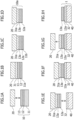
- FIG. 1 is a flow diagram illustrating an embodiment of a device substrate manufacturing method according to the present invention.
- the device substrate manufacturing method of this embodiment is mainly composed of a provisional bonding process of provisionally bonding an SOI device substrate to a support substrate using a provisional bonding adhesive, a Si base substrate removing process of removing a Si base substrate from the provisionally bonded SOI device substrate, a transfer bonding process of transfer-bonding a transfer substrate to a portion, where the Si base substrate is removed, using a transfer adhesive, a separation process of separating the support substrate, and an adhesive removing process of removing the remaining provisional bonding adhesive.
- the provisional bonding process will be described.
- An SOI device substrate 10 formed with a device and a support substrate 20 are bonded to each other using a provisional bonding adhesive 31 ( FIG. 1A ).
- the SOI device substrate 10 includes a Si base substrate 11, a Box layer (buried oxide film layer) 12 formed on the Si base substrate 11, and a Si device layer 13 formed on the Box layer 12.
- the thickness of the Si base substrate 11 is preferably 200 ⁇ m or more and more preferably 300 ⁇ m or more. By setting the thickness of the Si base substrate 11 to 200 ⁇ m or more, it is possible to convey the wafer without causing bending thereof.
- the upper limit of the thickness is not particularly limited, but in order to facilitate cutting, polishing, etching, or the like, described below, it is preferably set to 1000 ⁇ m or less.
- the Box layer 12 has a higher thermal conductivity than at least SiO 2 and is an electrical insulator. Specifically, the thermal conductivity is preferably higher than 1.5 W/m ⁇ K, more preferably 10 W/m ⁇ K or more, and further preferably 100 W/m ⁇ K or more. As such a material, there are AlN, Si 3 N 4 , Al 2 O 3 , diamond, and the like.
- the thickness of the Box layer 12 is preferably in a range from 50 to 10000 nm and more preferably in a range of 500 nm or less.
- the thickness is preferably in a range from 50 to 10000 nm and more preferably in a range of 500 nm or less.
- the thickness of the Si device layer 13 is normally 4 to 10 ⁇ m, but can be changed as appropriate according to the number of wires to be provided. By setting the thickness to 4 ⁇ m or more, multilayer wiring is enabled, and by setting the thickness to 10 ⁇ m or less, the necessary number of wires can be ensured.
- the thickness of the Si device layer 13 is more preferably in a range from 4 to 8 ⁇ m. Solder bumps may be formed on a surface of the Si device layer 13.
- the support substrate 20 although depending on a curing method of the provisional bonding adhesive 31 to be used, it is desirable to use a substrate with a linear expansion coefficient equivalent to that of Si.
- the linear expansion coefficient is preferably 5.0 ⁇ 10 -6 /°C or less.
- the linear expansion coefficient is greater than 5.0 ⁇ 10 -6 /°C, when the heat is applied at the time of provisional bonding, since the difference in thermal expansion coefficient with respect to the silicon of the Si device layer 13 is large, there is a possibility that the entire substrate warps.
- the provisional bonding adhesive 31 is not particularly limited as long as it is an adhesive that enables separation of two bonded layers from each other, and it is possible to use, for example, an acrylic adhesive, a silicone adhesive, an epoxy adhesive, a hot melt adhesive, or the like.
- an acrylic adhesive e.g., a silicone adhesive, an epoxy adhesive, a hot melt adhesive, or the like.
- the provisional bonding adhesive 31 it is possible to use WSS (UV curable acrylic-based adhesive) manufactured by 3M Company or an adhesive mainly composed of a thermosetting modified silicone such as TA1070T/TA2570V3/TA4070 manufactured by Shin-Etsu Chemical Co., Ltd.
- the provisional bonding adhesive the latter adhesive mainly composed of the thermosetting modified silicone that is excellent in acid/alkali resistance at the time of back surface etching.
- a plurality of layers of mutually different provisional bonding adhesives 31 may be formed on the support substrate 20.
- the thickness of the provisional bonding adhesive 31 is not particularly limited, but is preferably in a range from 10 to 200 ⁇ m.
- the Si base substrate removing process preferably includes a thinning process of thinning the Si base substrate 11, an edge trimming process of trimming outer peripheral portions of the SOI device substrate 10 and the provisional bonding adhesive 31 that are provisionally bonded to the support substrate 20, and an etching process of removing, by etching, the Si base substrate 11 remaining after those processes.
- the thinning process of the Si base substrate removing process will be described.
- the Si base substrate 11 of the SOI device substrate 10 is thinned ( FIG. 1B ).
- the Si base substrate 11 In order to prevent the machining distortion from affecting the Si device layer 13, it is preferable to leave the Si base substrate 11 by 10 to 100 ⁇ m, and the thickness to be left is more preferably 20 ⁇ m or more and 50 ⁇ m or less.
- the thickness of a thinned Si base substrate 11a By setting the thickness of a thinned Si base substrate 11a to 10 ⁇ m or more, the machining distortion hardly affects the Si device layer 13, and by setting the thickness thereof to 100 ⁇ m or less, the etching time for removing the thinned Si base substrate 11a by etching thereafter can be shortened.
- edge trimming process of the Si base substrate removing process After sufficiently thinning the Si base substrate 11 in the thinning process, edge trimming is performed ( FIG. 1C ).
- the layer of the provisional bonding adhesive 31 tends to be thickened at the outer peripheral portion of the SOI device substrate 10 compared to at the in-plane center thereof. Therefore, in order to leave a uniform thickness portion of the provisional bonding adhesive 31, the outer peripheral portions of the SOI device substrate 10 and the provisional bonding adhesive 31 are removed.
- the edge trimming amount can be determined as appropriate so that the residue of the provisional bonding adhesive 31 can be sufficiently removed while not reducing the area of a device portion.
- provisional bonding adhesive 31 is not coated on the support substrate 20, it is not necessary to perform the edge trimming of the support substrate 20.
- an edge trimming method there are grinding by a grinder, tape polishing using a polishing film, and the like.
- the tape polishing is preferable.
- the grinding by the grinder is performed, in a case in which the modified silicone is used as the provisional bonding adhesive 31, the grindstone is subjected to clogging due to the resin being soft so that seizure or separation of the substrate occurs.
- the edge trimming is performed by the tape polishing, separation of the Si device layer 13 from the support substrate 20, cracking thereof, or the like does not occur so that excellent trimming is enabled.
- etching is performed to completely remove a remaining Si base substrate 11b, thereby obtaining a thinned device wafer 10a ( FIG. 1D ).
- the etching can be performed with an acid or an alkali, but in terms of the etching rate, the etching with acid is preferable. This is because while it takes one hour or more at 70°C to etch the Si base substrate 11b of 20 ⁇ m by etching with an alkali such as KOH or NH 4 OH, it is possible to etch the same in several minutes at room temperature by etching with an acid.
- an acid to be used an acid obtained by freely selecting and mixing strong acids such as HF, HNO 3 , CH 3 COOH, H 2 SO 4 , and H 3 PO 4 is more preferable.
- the thinning by conventionally used grinding or CMP is not preferable due to the remaining of machining marks.
- wet etching is further preferable in terms of the etching rate.
- the etching is performed by immersion or single-side spin etching. In terms of suppressing etching of the support substrate 20, the single-side spin etching is preferable.
- a layer of a provisional bonding adhesive 31a is exposed at the outer peripheral portion of the SOI device substrate 10 by performing the edge trimming. When the provisional bonding adhesive 31 used has no resistance to an acid, the provisional bonding adhesive 31 is eroded by an etching solution from the outer peripheral portion of the SOI device substrate 10 so that wrinkles occur from the outer peripheral portion of the Si device layer 13 to cause separation.
- the provisional bonding adhesive 31 when WSS (UV curable acrylic-based adhesive) with no resistance to an acid manufactured by 3M Company is used as the provisional bonding adhesive 31, erosion occurs due to an acid to cause separation from the outer peripheral portion of the SOI device substrate 10, which is not suitable for use in the present invention.
- WSS UV curable acrylic-based adhesive
- a modified silicone-based adhesive having resistance to acid is used as the provisional bonding adhesive 31
- separation does not occur so that etching is enabled until the thin-film Box layer 12 having high thermal conductivity and being an electrical insulator is exposed.
- the substrate obtained in this process, with the Si base substrate 11b completely removed, will be referred to as the thinned device wafer 10a.
- a transfer adhesive 32 is coated on a transfer substrate 40 being an electrical insulator ( FIG. 1E ) and is bonded to the thinned device wafer 10a ( FIG. 1F ).
- the transfer substrate 40 makes it possible to obtain a wafer size of 200 to 300 mm in diameter. It is preferable to use sapphire, alumina, an AlN sintered body, a Si 3 N 4 sintered body, diamond, or the like. This is because these each have a higher thermal conductivity than SiO 2 and are electrical insulators, and further, these are preferable in terms of cost compared to a single crystal, which is generally expensive.
- the thermal conductivity is preferably higher than 1.5 W/m ⁇ K, more preferably 10 W/m ⁇ K or more, and further preferably 100 W/m ⁇ K or more.
- the transfer adhesive 32 has a resistance to a temperature of 250°C, and more preferably to a temperature of 300°C, and, in order to reduce the stress to the Si device layer 13 at the time of transfer bonding, it is preferable to use a silicone resin, an epoxy modified rubber, an epoxy modified silicone, or the like.
- the epoxy modified silicone is most preferable because the strength as an adhesive is high, the thermal stress at the time of curing is small, it can be formed to be thin, and the bonding force is maintained.
- the thermosetting modified silicones such as TA1070T, TA2570V3, and TA4070 manufactured by Shin-Etsu Chemical Co., Ltd. are preferable.
- the thickness of the layer of the transfer adhesive 32 is preferably 0.1 to 5 ⁇ m, more preferably 0.1 ⁇ m or more and 2 ⁇ m or less, and further preferably 0.1 ⁇ m or more and 1 ⁇ m or less.
- the thickness of the layer of the transfer adhesive 32 exceeds 5 ⁇ m, the heat dissipation becomes 1/2 or less compared to a case in which the transfer adhesive 32 is not provided, and therefore, it is preferable to provide the transfer adhesive 32 of 5 ⁇ m or less for enhancing the thermal conductivity.
- the thickness By setting the thickness to 0.1 ⁇ m or more, it is possible to maintain the sufficient bonding strength and to uniformly coat the transfer adhesive 32 in the plane thereby to facilitate the bonding.
- the thermal conductivity of the transfer adhesive 32 is as small as about 1 W/m ⁇ K, and therefore, in order to manufacture a substrate with a high thermal conductivity, it is preferable to form the transfer adhesive 32 to be thin and uniform as much as possible.
- a thin film made of one selected from a group including SiO 2 , Si 3 N 4 , and oxynitrides (SiO x N y ) or a combination thereof may be formed on a bonding surface of the transfer substrate 40 to a Box layer 12a.
- the thickness of the thin film is preferably in a range from 0.05 to 10 ⁇ m.
- a film forming method is not particularly limited, but, for example, a plasma film forming method, a chemical vapor deposition method, a physical vapor deposition method, and the like are preferable.
- the thin film may be formed on a surface of the Box layer 12a of the thinned device wafer 10a instead of, or in addition to, forming it on the transfer substrate 40.
- the Box layer 12a is exposed at the surface of the thinned device wafer 10a.
- the Box layer 12a is normally 50 to 1000 nm, but after the Si base substrate 11b is completely removed, the Box layer 12a is locally deformed due to local stresses by pattern wiring of the Si device layer 13 so that steps of 1 to 10 nm in height occur corresponding to the wiring pattern. With these steps, it is not possible to bond the Box layer 12a to the transfer substrate 40 by direct bonding or plasma bonding. Therefore, in order to bond the surface with the steps to the transfer substrate 40, the bonding is performed via the transfer adhesive 32.
- the transfer adhesive 32 After the transfer adhesive 32 is coated, it is preferable to perform baking and halfcuring at 100 to 200°C for removing a solvent and preventing degassing due to heating at the time of bonding.
- the temperature is 120°C or more and 180°C or less.
- the transfer adhesive 32 As a method of coating the transfer adhesive 32, it is possible to use a method such as die coating, slit coating, dip coating, or spin coating.
- the spin coating is preferable because it enables uniform coating only on the bonding surface side.
- the upper limit of the load By setting the upper limit of the load to less than 20 kgf/cm 2 , it is possible to perform the bonding with a load that does not cause deformation of the Si device layer 13, particularly the solder bumps thereof. On the other hand, it is preferable to apply a load of 1 kgf/cm 2 or more. By setting the load to 1 kgf/cm 2 or more, the stacking is performed while correcting a warp of 5 to 50 ⁇ m which the transfer substrate 40 itself has. The thinned device wafer 10a and the transfer substrate 40 both can have the warps, and these warps can be corrected by applying the load at the time of the bonding.
- the transfer bonding can be performed in either an atmospheric or under a vacuum, but is preferably performed under a vacuum of 1E -1 to 1E -5 Torr and preferably 1E -2 to 1E -4 Torr. By setting the vacuum to 1E -5 Torr or more, the transfer bonding can be performed to prevent air bubbles from remaining at the bonding interface.
- the transfer bonding process is the method of transferring a Si device layer 13a without inverting it, the transfer can be performed in the state in which the Si device layer 13a is formed with up to the solder bumps, and therefore, there is no need for a process to form active portions, such as electrical wiring, after the transfer.
- the adhesive removing process will be described ( FIG. 1H ). As needed, the adhesive removing process can be performed to clean the residue of the provisional bonding adhesive 31a remaining on the surface of the Si device layer 13a. Since the provisional bonding adhesive 31 is swollen by an organic solvent such as p-menthane, it is possible to easily remove the residue of the provisional bonding adhesive 31a by immersing the Si device layer 13a in p-menthane. The immersion time is 1 to 10 minutes and preferably 3 to 5 minutes.
- the device substrate manufacturing method of this embodiment it is possible to obtain a device substrate 1 in which the Si device layer 13a, the Box layer 12a, and the transfer substrate 40 are stacked via the transfer adhesive 32.
- the device substrate manufacturing method of this embodiment does not require a high temperature process that causes diffusion of metal impurities.
- the Box layer 12a and the transfer substrate 40 each have the high thermal conductivity and are electrical insulators, thus resulting in excellent heat dissipation and a small loss at high frequencies.
- the Si base substrate 11 of the SOI device substrate 10 is removed under predetermined conditions suitable for the removal, there is no occurrence of separation from the support substrate 20.
- an SOI device substrate formed with a device use was made of a wafer including a Si device layer with an outer diameter of 300 mm and a thickness of 4 ⁇ m, a thin-film Box layer with a thickness of 250 nm made of AlN, and a Si base substrate with a thickness of 725 ⁇ m. Solder bumps each having a diameter of 80 ⁇ m were formed on an outermost surface of the device at a minimum pitch of 150 ⁇ m.
- silicone resin adhesives TA1070T/TA2570V3/TA4070 manufactured by Shin-Etsu Chemical Co., Ltd. were stacked and coated by spin coating on a surface, provided with the Si device layer, of the SOI device substrate. Specifically, first, TA1070T was stacked to 10 ⁇ m as a device protection layer, then TA2570V3 was stacked to 10 ⁇ m as a layer serving as a separation surface of a support substrate after processing, and then TA4070 was stacked to 100 ⁇ m as a bonding layer to the support substrate. A Si wafer was used as the support substrate.
- the provisional bonding adhesive and the support substrate were held and bonded to each other under a vacuum of 10 -4 Torr with a load of 1 kgf/cm 2 at 140°C, and then the provisional bonding adhesive was cured by a treatment in an oven at 190°C for 2 hours.
- the Si base substrate located on the back side of the SOI device substrate was thinned to a thickness of 40 ⁇ m by the use of a #2000 grindstone. Although saw marks were observed on a surface after the grinding, separation, cracking, or edge chipping of the wafer was not observed.
- edge trimming was performed by tape polishing.
- the trimming width was set to 2 mm inward from the outermost periphery of the wafer. The trimming was performed without causing cracking or separation.
- the Si base substrate of 40 ⁇ m in thickness remaining on the back side was removed by spin etching with an acid.
- the acid used was a mixed acid of HF/HNO 3 /H 3 PO 4 /H 2 SO 4 , and the Si base substrate was completely removed in an etching time of 3 minutes, thereby obtaining a thinned device wafer.
- a transfer substrate having high thermal conductivity and being an electrical insulator use was made of an AlN sintered body substrate with an outer diameter of 300 mm, a thickness of 725 ⁇ m, a thermal conductivity of 200 W/m ⁇ K, and a resistivity of 5E +15 ⁇ cm.
- TA4070 being a thermosetting epoxy modified silicone adhesive with low stress was diluted with cyclopentanone to prepare a coating solution with a 0.5 wt% adhesive concentration.
- the coating solution was spin-coated on the AlN wafer prepared as the transfer substrate so that a layer of the transfer adhesive with a thickness of 1 ⁇ m was formed with an in-plane variation of ⁇ 5%.
- the transfer substrate coated with the transfer adhesive was baked at 150 °C for 5 minutes, thereby performing solvent removal and halfcuring.
- the thinned device wafer and the transfer substrate were bonded to each other.
- the transfer substrate coated with the transfer adhesive and the thinned device wafer were stacked with each other at room temperature and then were bonded to each other by applying a load of 3 kgf/cm 2 and holding them under a vacuum of 1E -4 Torr at 240°C for 10 minutes. Thereafter, the load was released at a temperature of 65°C or less, and the bonded wafer was taken out.
- the Si device layer was transferred to the transfer substrate via the Box layer. In appearance, there was no separation of the transferred Si device layer. Further, as a result of observing a device pattern in the plane using an optical microscope, there was no separation of the pattern, and separation of the solder bumps was also not observed.
- the Box layer with the Si device layer transferred thereto was immersed in p-menthane for 5 minutes, thereby removing the provisional bonding adhesive remaining on the surface. No separation was observed at the interface between the transferred Si device layer and the Box layer, and the transfer adhesive was not eluted by p-menthane. As a result of observing the device surface after cleaning using the optical microscope, separation of the pattern or deformation of the solder bumps was not observed. In this way, the Si device layer was transferred to the Box layer in the state in which the original device pattern was maintained. After dividing individual devices from the transfer substrate, a high frequency of 1 GHz was applied thereto and the surface temperature of the devices was measured after one hour, and as a result, the rise in temperature was hardly observed. Further, isolation between signal and noise was extremely high and thus was excellent.
- Example 2 There was prepared an SOI device substrate that was the same as that of Example 1 except that diamond synthesized from a mixed gas of methane and hydrogen, having high thermal conductivity, being an electrical insulator, and having a thickness of 200 nm was used as a Box layer, and a device substrate was manufactured via a thinned device wafer in the same manner as in Example 1.
- a Si 3 N 4 substrate was used as a transfer substrate instead of the AlN substrate. Coating of a transfer adhesive was performed in the same manner, but bonding was performed by reducing the load to 1 kgf/cm 2 .
- the thinned device wafer was uniformly bonded.
- a Si device layer was transferred to the transfer substrate via the Box layer.
- separation or deformation of bumps was not observed.
- the rise in temperature of the transfer substrate under the same conditions as in Example 1 the temperature rose by about 3°C from that before the measurement, but thereafter, no further temperature rise was observed so that the temperature was substantially constant and stable. Further, isolation was excellent.
- Example 2 There was prepared an SOI device substrate that was formed in the same manner as in Example 1 except that a Box layer of the SOI device substrate was Al 2 O 3 coated by a sputtering method, having high thermal conductivity, being an electrical insulator, and having a thickness of 150 nm, and a device substrate was manufactured via a thinned device wafer in the same manner as in Example 1. Coating of a transfer adhesive on the Box layer was performed in the same manner, but bonding was performed by increasing the load to 10 kgf/cm 2 .
- the thinned device wafer was well bonded.
- a Si device layer was transferred to a transfer substrate via the Box layer.
- separation or deformation of bumps was not observed.
- Example 2 There was prepared an SOI device substrate described in Example 1, and a device substrate was manufactured via a thinned device wafer in the same manner as in Example 1.
- a Si 3 N 4 substrate was used as a transfer substrate instead of the AlN substrate, and SiO 2 was coated to about 1 ⁇ m on a bonding surface to a Box layer by a plasma film forming method in advance, and then polishing was performed to achieve smoothing to Ra 0.5 nm.
- coating of a transfer adhesive was performed in the same manner as in Example 1, but bonding was performed by reducing the temperature to 220°C.
- the thinned device wafer was bonded.
- a Si device layer was transferred to the transfer substrate via the Box layer.
- separation or deformation of bumps was not observed so that a fine state was maintained.
- the rise in temperature in the same manner as in Example 1 the temperature was about 7.5°C and was constant thereafter. There was no particular problem for isolation.
- Example 2 There was prepared an SOI device substrate described in Example 1, and a device substrate was manufactured via a thinned device wafer in the same manner as in Example 1. However, a sapphire substrate was used as a transfer substrate instead of the AlN substrate, and, in coating of a transfer adhesive, a coating solution with a 0.05 wt% adhesive concentration was prepared, and the layer thickness of the transfer adhesive after coating was made to be 0.1 ⁇ m.
- the thinned device wafer was bonded.
- a Si device layer was transferred except a region of 10 mm from the outer periphery. Since most of the transfer was achieved, it was seen that providing a layer of the transfer adhesive having a thickness of at least 0.1 ⁇ m or more was necessary for the transfer of the entire surface.
- the rise in temperature of individual devices was measured under the same conditions as in Example 1. A temperature rise of about 11°C was observed, but the temperature was constant thereafter and no particular problem occurred. There was no particular problem for isolation in practical use.
- Example 1 There was prepared a normal SOI device substrate of 200 mm in diameter in which a SiO 2 Box layer of 100 nm in thickness was formed on a Si base substrate and an Si device layer that was the same as that of Example 1 was formed, and a device substrate was manufactured via a thinned device wafer in the same manner as in Example 1 except that a transfer substrate of synthetic quartz was used instead of the transfer substrate of the AlN sintered body.
- a transfer substrate of synthetic quartz was used instead of the transfer substrate of the AlN sintered body.
- Example 2 There was prepared an SOI device substrate that was the same as that of Example 1, and a device substrate was manufactured via a thinned device wafer in the same manner as in Example 1.
- a liquid epoxy resin with a heat-resistant temperature of 120°C was used as a transfer adhesive and was coated not on a transfer substrate made of AlN, but on the thinned device wafer side by spin coating, and baking was performed at 110°C.
- the thinned device wafer was subjected to wrinkles and separated from a support substrate. That is, they were not bonded to each other, and in the state in which the thickness of the thinned device wafer was thin, it was not possible to suppress deformation of a provisional bonding adhesive due to heat so that the wrinkles occurred.
- the transfer substrate since the heat-resistant temperature of the transfer adhesive was low, the transfer substrate also could not bear soldering heat so that most of devices of the transfer substrate were subjected to conduction failure.
- the WSS was a UV curable acrylic-based adhesive, and it was configured that a separation layer was provided by irradiating YAG laser. Therefore, the support substrate needed to be transparent in the UV to near infrared region, and herein a TEMPAX substrate was used as the support substrate. Other than this, the back surface was ground, edge trimming was performed, and etching with an acid was performed in the same manner as in Example 1. An outer peripheral portion of a device wafer after the trimming was separated, and wrinkles occurred toward the center of the substrate. This is because a UV absorbing layer used as the WSS was eroded by the acid and separated from the support substrate.
Landscapes
- Engineering & Computer Science (AREA)
- Chemical & Material Sciences (AREA)
- Organic Chemistry (AREA)
- Computer Hardware Design (AREA)
- Physics & Mathematics (AREA)
- Condensed Matter Physics & Semiconductors (AREA)
- General Physics & Mathematics (AREA)
- Manufacturing & Machinery (AREA)
- Mechanical Treatment Of Semiconductor (AREA)
- Microelectronics & Electronic Packaging (AREA)
- Power Engineering (AREA)
- Crystallography & Structural Chemistry (AREA)
- Superconductors And Manufacturing Methods Therefor (AREA)
Claims (12)
- Vorrichtungssubstrat (10), umfassend:eine vergrabene Oxidschicht (12), die eine höhere Wärmeleitfähigkeit als zumindest SiO2 aufweist und ein elektrischer Isolator ist;eine Si-Vorrichtungsschicht (13), die auf einer Oberfläche der vergrabenen Oxidschicht (12) gebildet ist;ein Substrat (40), das eine höhere Wärmeleitfähigkeit als zumindest SiO2 aufweist und ein elektrischer Isolator ist, wobei das Substrat (40) auf einer gegenüberliegenden Oberfläche der vergrabenen Oxidschicht (12) gebildet ist; undeinen Klebstoff (32), der eine hitzebeständige Temperatur von zumindest 250 °C aufweist, wobei der Klebstoff (32) zwischen der vergrabenen Oxidschicht (12) und dem Substrat (40) gebildet ist.
- Vorrichtungssubstrat (10) nach Anspruch 1, wobei die vergrabene Oxidschicht (12) aus einem gefertigt ist, das ausgewählt ist aus einer Gruppe, bestehend aus AlN, Si3N4, Al2O3 und Diamant und einer Kombination davon.
- Vorrichtungssubstrat (10) nach Anspruch 1 oder 2, wobei das Substrat (40) eine Keramik oder ein Einkristall ist, der ausgewählt ist aus einer Gruppe, bestehend aus AlN, Si3N4 und Al2O3 und einer Kombination davon.
- Vorrichtungssubstrat (10) nach einem der Ansprüche 1 bis 3, ferner umfassend eine Schicht, die zwischen der vergrabenen Oxidschicht und dem Substrat gebildet ist und aus einem gefertigt ist, das ausgewählt ist aus einer Gruppe, bestehend aus SiO2, Si3N4 und Oxynitriden (SiOxNy) und einer Kombination davon.
- Vorrichtungssubstrat (10) nach einem der Ansprüche 1 bis 4, wobei der Klebstoff (32) ein wärmehärtendes epoxidmodifiziertes Silikon ist.
- Vorrichtungssubstrat (10) nach einem der Ansprüche 1 bis 5, wobei die Stärke des Klebstoffs 0,1 bis 5 µm ist.
- Verfahren zum Herstellen eines Vorrichtungssubstrats (10), umfassend:einen provisorischen Bindungsschritt eines provisorischen Bindens einer Seite einer Si-Vorrichtungsschicht (13) eines SOI-Vorrichtungssubstrats (10) an ein Trägersubstrat (20) unter Verwendung eines provisorischen Bindungsklebstoffs (31), wobei das SOI-Vorrichtungssubstrat (10) ein Si-Basissubstrat (11), eine auf dem Si-Basissubstrat (11) gebildete vergrabene Oxidschicht (12) und eine auf der vergrabenen Oxidschicht (12) gebildete Si-Vorrichtungsschicht (13) beinhaltet, wobei die vergrabene Oxidschicht (12) eine höhere Wärmeleitfähigkeit aufweist als zumindest SiO2 und ein elektrischer Isolator ist;einen Si-Basissubstrat-Entfernungsschritt eines Entfernens des Si-Basissubstrats (11) des provisorisch gebundenen SOI-Vorrichtungssubstrats (10) durch eines, das ausgewählt ist aus einer Gruppe, bestehend aus Schleifen, Polieren und Ätzen und einer Kombination davon, bis die vergrabene Oxidschicht (12) freigelegt ist, um einen ausgedünnten Vorrichtungswafer zu erlangen,einen Übertragungsbindungsschritt eines Übertragungsbindens der Seite der vergrabenen Oxidschicht (12) des ausgedünnten Vorrichtungswafers und eines Übertragungssubstrats (40) aneinander unter Verwendung eines Übertragungsklebstoffs (32), der eine hitzebeständige Temperatur von zumindest 250 °C aufweist, durch Anwenden von Wärme und Druck; undeinen Trennungsschritt eines Trennens des Trägersubstrats (20) von der Si-Vorrichtungsschicht (13).
- Vorrichtungssubstrat-Herstellungsverfahren nach Anspruch 7, ferner umfassend einen Klebstoffentfernungsschritt eines Entfernens des provisorischen Bindungsklebstoffs (31), der nach dem Trennungsschritt auf einer Oberfläche der Si-Vorrichtungsschicht (13) verbleibt.
- Vorrichtungssubstrat-Herstellungsverfahren nach Anspruch 7 oder 8, wobei ein Silikonharz mit ausgezeichneter Säurebeständigkeit als provisorischer Bindungsklebstoff (31) verwendet wird.
- Vorrichtungssubstrat-Herstellungsverfahren nach einem der Ansprüche 7 bis 9, wobei die vergrabene Oxidschicht (12) aus einem gefertigt ist, das ausgewählt ist aus der Gruppe, bestehend aus AlN, Si3N4, Al2O3 und Diamant sowie einer Kombination davon.
- Vorrichtungssubstrat-Herstellungsverfahren nach einem der Ansprüche 7 bis 10, ferner umfassend einen Schritt eines Bildens einer Schicht auf einer Bindungsfläche der vergrabenen Oxidschicht (12) an das Übertragungssubstrat (40) und/oder einer Bindungsfläche des Übertragungssubstrats (40) an die vergrabene Oxidschicht (12), wobei die Schicht aus einem gefertigt ist, das ausgewählt ist aus der Gruppe, bestehend aus SiO2, Si3N4 und Oxynitriden (SiOxNy) und einer Kombination davon.
- Vorrichtungssubstrat-Herstellungsverfahren nach einem der Ansprüche 7 bis 11, wobei das Übertragungssubstrat (40) eine Keramik oder ein Einkristall ist, der aus einem gefertigt ist, das ausgewählt ist aus der Gruppe, bestehend aus AlN, Si3N4 und Al2O3 und einer Kombination davon.
Applications Claiming Priority (2)
| Application Number | Priority Date | Filing Date | Title |
|---|---|---|---|
| JP2017138026 | 2017-07-14 | ||
| PCT/JP2018/026068 WO2019013212A1 (ja) | 2017-07-14 | 2018-07-10 | 高熱伝導性のデバイス基板およびその製造方法 |
Publications (3)
| Publication Number | Publication Date |
|---|---|
| EP3654366A1 EP3654366A1 (de) | 2020-05-20 |
| EP3654366A4 EP3654366A4 (de) | 2021-04-14 |
| EP3654366B1 true EP3654366B1 (de) | 2024-08-07 |
Family
ID=65002076
Family Applications (1)
| Application Number | Title | Priority Date | Filing Date |
|---|---|---|---|
| EP18832873.6A Active EP3654366B1 (de) | 2017-07-14 | 2018-07-10 | Hochwärmeleitendes vorrichtungssubstrat und verfahren zur herstellung davon |
Country Status (8)
| Country | Link |
|---|---|
| US (1) | US11361969B2 (de) |
| EP (1) | EP3654366B1 (de) |
| JP (1) | JP6854895B2 (de) |
| KR (1) | KR102558905B1 (de) |
| CN (1) | CN110892506B (de) |
| SG (2) | SG10201913156WA (de) |
| TW (1) | TWI798236B (de) |
| WO (1) | WO2019013212A1 (de) |
Families Citing this family (6)
| Publication number | Priority date | Publication date | Assignee | Title |
|---|---|---|---|---|
| JP6431631B1 (ja) | 2018-02-28 | 2018-11-28 | 株式会社フィルネックス | 半導体素子の製造方法 |
| JP7016445B2 (ja) * | 2019-02-25 | 2022-02-04 | 三菱電機株式会社 | 半導体素子の製造方法 |
| JP7041648B2 (ja) * | 2019-07-17 | 2022-03-24 | 信越化学工業株式会社 | 複合基板の製造方法 |
| JP7186921B2 (ja) * | 2020-04-13 | 2022-12-09 | 三菱電機株式会社 | 半導体素子の製造方法 |
| CN112930106B (zh) * | 2021-01-22 | 2022-11-22 | 杭州唯灵医疗科技有限公司 | 一种柔性电子设备及柔性电子设备的组装方法 |
| JP7666608B2 (ja) * | 2021-08-17 | 2025-04-22 | 信越半導体株式会社 | 仮接合ウェーハ及びその製造方法 |
Family Cites Families (22)
| Publication number | Priority date | Publication date | Assignee | Title |
|---|---|---|---|---|
| US20020134503A1 (en) | 2001-03-20 | 2002-09-26 | Accucorp Technical Services, Inc. | Silicon wafers bonded to insulator substrates by low viscosity epoxy wicking |
| JP2004047975A (ja) * | 2002-05-17 | 2004-02-12 | Semiconductor Energy Lab Co Ltd | 積層体の転写方法及び半導体装置の作製方法 |
| DE60325669D1 (de) | 2002-05-17 | 2009-02-26 | Semiconductor Energy Lab | Verfahren zum Transferieren eines Objekts und Verfahren zur Herstellung eines Halbleiterbauelements |
| JP2005129825A (ja) * | 2003-10-27 | 2005-05-19 | Sumitomo Chemical Co Ltd | 化合物半導体基板の製造方法 |
| WO2005065402A2 (en) * | 2003-12-29 | 2005-07-21 | Translucent Photonics, Inc. | Rare earth-oxides, rare earth-nitrides, rare earth-phosphides and ternary alloys with silicon |
| JP4389626B2 (ja) | 2004-03-29 | 2009-12-24 | ソニー株式会社 | 固体撮像素子の製造方法 |
| JP2007266044A (ja) * | 2006-03-27 | 2007-10-11 | New Japan Radio Co Ltd | 半導体装置の製造方法 |
| CN101548369B (zh) * | 2006-12-26 | 2012-07-18 | 硅绝缘体技术有限公司 | 制造绝缘体上半导体结构的方法 |
| JP2008218814A (ja) * | 2007-03-06 | 2008-09-18 | Sumitomo Electric Ind Ltd | パワーモジュール |
| CN101952952B (zh) * | 2008-02-26 | 2013-01-30 | 京瓷株式会社 | 晶片支承部及其制造方法、以及使用该晶片的静电夹头 |
| US8092628B2 (en) * | 2008-10-31 | 2012-01-10 | Brewer Science Inc. | Cyclic olefin compositions for temporary wafer bonding |
| US8440544B2 (en) * | 2010-10-06 | 2013-05-14 | International Business Machines Corporation | CMOS structure and method of manufacture |
| KR20140118984A (ko) * | 2011-11-04 | 2014-10-08 | 더 실라나 그룹 피티와이 리미티드 | 실리콘-온-인슐레이터 물품 제조방법 |
| JP5928481B2 (ja) | 2011-12-22 | 2016-06-01 | 信越化学工業株式会社 | 複合基板 |
| CN104272432B (zh) * | 2012-05-08 | 2018-05-11 | 信越化学工业株式会社 | 放热基板及其制造方法 |
| JP2014086665A (ja) * | 2012-10-26 | 2014-05-12 | Sumitomo Electric Ind Ltd | Iii族窒化物ドナー複合基板およびその製造方法、ならびにiii族窒化物複合基板およびその製造方法 |
| JP6168143B2 (ja) * | 2013-05-01 | 2017-07-26 | 信越化学工業株式会社 | ハイブリッド基板の製造方法 |
| FR3012604B1 (fr) * | 2013-10-25 | 2017-03-03 | Auxitrol Sa | Capteur de pression comprenant une structure de controle d'une couche d'adhesif resistante aux variations de temperatures |
| JP6208646B2 (ja) | 2014-09-30 | 2017-10-04 | 信越化学工業株式会社 | 貼り合わせ基板とその製造方法、および貼り合わせ用支持基板 |
| CN104617195B (zh) * | 2015-02-06 | 2017-10-17 | 扬州乾照光电有限公司 | 一种近红外发光二极管及其生产方法 |
| CN105140122B (zh) * | 2015-08-10 | 2018-07-20 | 中国电子科技集团公司第五十五研究所 | 一种改善GaN HEMT器件散热性能的方法 |
| JP6715345B2 (ja) * | 2016-11-01 | 2020-07-01 | 信越化学工業株式会社 | デバイス層を転写基板に転写する方法 |
-
2018
- 2018-07-10 SG SG10201913156WA patent/SG10201913156WA/en unknown
- 2018-07-10 JP JP2019529733A patent/JP6854895B2/ja active Active
- 2018-07-10 WO PCT/JP2018/026068 patent/WO2019013212A1/ja not_active Ceased
- 2018-07-10 CN CN201880046539.7A patent/CN110892506B/zh active Active
- 2018-07-10 SG SG11201912503WA patent/SG11201912503WA/en unknown
- 2018-07-10 EP EP18832873.6A patent/EP3654366B1/de active Active
- 2018-07-10 KR KR1020197037807A patent/KR102558905B1/ko active Active
- 2018-07-10 US US16/626,154 patent/US11361969B2/en active Active
- 2018-07-13 TW TW107124206A patent/TWI798236B/zh active
Also Published As
| Publication number | Publication date |
|---|---|
| KR102558905B1 (ko) | 2023-07-21 |
| US20200227263A1 (en) | 2020-07-16 |
| EP3654366A1 (de) | 2020-05-20 |
| JPWO2019013212A1 (ja) | 2020-04-16 |
| TW201908124A (zh) | 2019-03-01 |
| SG11201912503WA (en) | 2020-01-30 |
| EP3654366A4 (de) | 2021-04-14 |
| CN110892506B (zh) | 2024-04-09 |
| TWI798236B (zh) | 2023-04-11 |
| CN110892506A (zh) | 2020-03-17 |
| KR20200026822A (ko) | 2020-03-11 |
| WO2019013212A1 (ja) | 2019-01-17 |
| JP6854895B2 (ja) | 2021-04-07 |
| SG10201913156WA (en) | 2020-02-27 |
| US11361969B2 (en) | 2022-06-14 |
Similar Documents
| Publication | Publication Date | Title |
|---|---|---|
| US11876014B2 (en) | Method of transferring device layer to transfer substrate and highly thermal conductive substrate | |
| EP3654366B1 (de) | Hochwärmeleitendes vorrichtungssubstrat und verfahren zur herstellung davon | |
| JP3900741B2 (ja) | Soiウェーハの製造方法 | |
| CN102034687A (zh) | 键合和转移层的工艺 | |
| JP2012064710A (ja) | 半導体素子の製造方法 | |
| CN109712926B (zh) | 一种半导体器件的制造方法 | |
| CN108242393B (zh) | 一种半导体器件的制造方法 | |
| WO2015057719A1 (en) | Method of providing a flexible semiconductor device and flexible semiconductor device thereof | |
| TW202006088A (zh) | 附電路基板加工體及附電路基板加工方法 | |
| WO2020008882A1 (ja) | デバイス層転写基板の製造方法及びデバイス層転写基板 | |
| TWI716627B (zh) | 貼合式soi晶圓的製造方法 | |
| KR102666195B1 (ko) | 층의 전사 방법 | |
| JP2009537076A (ja) | 絶縁体上半導体構造を形成するための方法 | |
| CN115428127A (zh) | 半导体元件的制造方法 | |
| TW201005883A (en) | Method for manufacturing soi wafer | |
| US20090081880A1 (en) | Method for manufacturing semiconductor device | |
| TWI786782B (zh) | 製造絕緣體上矽晶片的方法 | |
| KR102568640B1 (ko) | 도너 기판의 잔류물을 제조하는 방법, 그 방법에 의해 제조된 기판 및 그 기판의 사용 | |
| KR20230074056A (ko) | 단결정 박막의 전사방법 및 이를 이용한 반도체 소자의 제조방법 |
Legal Events
| Date | Code | Title | Description |
|---|---|---|---|
| STAA | Information on the status of an ep patent application or granted ep patent |
Free format text: STATUS: THE INTERNATIONAL PUBLICATION HAS BEEN MADE |
|
| PUAI | Public reference made under article 153(3) epc to a published international application that has entered the european phase |
Free format text: ORIGINAL CODE: 0009012 |
|
| STAA | Information on the status of an ep patent application or granted ep patent |
Free format text: STATUS: REQUEST FOR EXAMINATION WAS MADE |
|
| 17P | Request for examination filed |
Effective date: 20200110 |
|
| AK | Designated contracting states |
Kind code of ref document: A1 Designated state(s): AL AT BE BG CH CY CZ DE DK EE ES FI FR GB GR HR HU IE IS IT LI LT LU LV MC MK MT NL NO PL PT RO RS SE SI SK SM TR |
|
| AX | Request for extension of the european patent |
Extension state: BA ME |
|
| DAV | Request for validation of the european patent (deleted) | ||
| DAX | Request for extension of the european patent (deleted) | ||
| A4 | Supplementary search report drawn up and despatched |
Effective date: 20210316 |
|
| RIC1 | Information provided on ipc code assigned before grant |
Ipc: H01L 21/02 20060101AFI20210310BHEP Ipc: H01L 27/12 20060101ALI20210310BHEP Ipc: H01L 21/20 20060101ALI20210310BHEP Ipc: H01L 21/762 20060101ALN20210310BHEP |
|
| GRAP | Despatch of communication of intention to grant a patent |
Free format text: ORIGINAL CODE: EPIDOSNIGR1 |
|
| STAA | Information on the status of an ep patent application or granted ep patent |
Free format text: STATUS: GRANT OF PATENT IS INTENDED |
|
| RIC1 | Information provided on ipc code assigned before grant |
Ipc: H01L 21/762 20060101ALN20231116BHEP Ipc: H01L 21/20 20060101ALI20231116BHEP Ipc: H01L 27/12 20060101ALI20231116BHEP Ipc: H01L 21/02 20060101AFI20231116BHEP |
|
| INTG | Intention to grant announced |
Effective date: 20231129 |
|
| GRAJ | Information related to disapproval of communication of intention to grant by the applicant or resumption of examination proceedings by the epo deleted |
Free format text: ORIGINAL CODE: EPIDOSDIGR1 |
|
| STAA | Information on the status of an ep patent application or granted ep patent |
Free format text: STATUS: REQUEST FOR EXAMINATION WAS MADE |
|
| GRAP | Despatch of communication of intention to grant a patent |
Free format text: ORIGINAL CODE: EPIDOSNIGR1 |
|
| STAA | Information on the status of an ep patent application or granted ep patent |
Free format text: STATUS: GRANT OF PATENT IS INTENDED |
|
| INTC | Intention to grant announced (deleted) | ||
| RIC1 | Information provided on ipc code assigned before grant |
Ipc: H01L 21/762 20060101ALN20240311BHEP Ipc: H01L 21/20 20060101ALI20240311BHEP Ipc: H01L 27/12 20060101ALI20240311BHEP Ipc: H01L 21/02 20060101AFI20240311BHEP |
|
| INTG | Intention to grant announced |
Effective date: 20240327 |
|
| GRAS | Grant fee paid |
Free format text: ORIGINAL CODE: EPIDOSNIGR3 |
|
| GRAA | (expected) grant |
Free format text: ORIGINAL CODE: 0009210 |
|
| STAA | Information on the status of an ep patent application or granted ep patent |
Free format text: STATUS: THE PATENT HAS BEEN GRANTED |
|
| AK | Designated contracting states |
Kind code of ref document: B1 Designated state(s): AL AT BE BG CH CY CZ DE DK EE ES FI FR GB GR HR HU IE IS IT LI LT LU LV MC MK MT NL NO PL PT RO RS SE SI SK SM TR |
|
| REG | Reference to a national code |
Ref country code: GB Ref legal event code: FG4D |
|
| REG | Reference to a national code |
Ref country code: CH Ref legal event code: EP |
|
| REG | Reference to a national code |
Ref country code: IE Ref legal event code: FG4D |
|
| REG | Reference to a national code |
Ref country code: DE Ref legal event code: R096 Ref document number: 602018072880 Country of ref document: DE |
|
| REG | Reference to a national code |
Ref country code: LT Ref legal event code: MG9D |
|
| REG | Reference to a national code |
Ref country code: NL Ref legal event code: MP Effective date: 20240807 |
|
| PG25 | Lapsed in a contracting state [announced via postgrant information from national office to epo] |
Ref country code: NO Free format text: LAPSE BECAUSE OF FAILURE TO SUBMIT A TRANSLATION OF THE DESCRIPTION OR TO PAY THE FEE WITHIN THE PRESCRIBED TIME-LIMIT Effective date: 20241107 |
|
| REG | Reference to a national code |
Ref country code: AT Ref legal event code: MK05 Ref document number: 1711924 Country of ref document: AT Kind code of ref document: T Effective date: 20240807 |
|
| PG25 | Lapsed in a contracting state [announced via postgrant information from national office to epo] |
Ref country code: NL Free format text: LAPSE BECAUSE OF FAILURE TO SUBMIT A TRANSLATION OF THE DESCRIPTION OR TO PAY THE FEE WITHIN THE PRESCRIBED TIME-LIMIT Effective date: 20240807 Ref country code: PT Free format text: LAPSE BECAUSE OF FAILURE TO SUBMIT A TRANSLATION OF THE DESCRIPTION OR TO PAY THE FEE WITHIN THE PRESCRIBED TIME-LIMIT Effective date: 20241209 Ref country code: FI Free format text: LAPSE BECAUSE OF FAILURE TO SUBMIT A TRANSLATION OF THE DESCRIPTION OR TO PAY THE FEE WITHIN THE PRESCRIBED TIME-LIMIT Effective date: 20240807 Ref country code: PL Free format text: LAPSE BECAUSE OF FAILURE TO SUBMIT A TRANSLATION OF THE DESCRIPTION OR TO PAY THE FEE WITHIN THE PRESCRIBED TIME-LIMIT Effective date: 20240807 Ref country code: GR Free format text: LAPSE BECAUSE OF FAILURE TO SUBMIT A TRANSLATION OF THE DESCRIPTION OR TO PAY THE FEE WITHIN THE PRESCRIBED TIME-LIMIT Effective date: 20241108 |
|
| PG25 | Lapsed in a contracting state [announced via postgrant information from national office to epo] |
Ref country code: BG Free format text: LAPSE BECAUSE OF FAILURE TO SUBMIT A TRANSLATION OF THE DESCRIPTION OR TO PAY THE FEE WITHIN THE PRESCRIBED TIME-LIMIT Effective date: 20240807 |
|
| PG25 | Lapsed in a contracting state [announced via postgrant information from national office to epo] |
Ref country code: LV Free format text: LAPSE BECAUSE OF FAILURE TO SUBMIT A TRANSLATION OF THE DESCRIPTION OR TO PAY THE FEE WITHIN THE PRESCRIBED TIME-LIMIT Effective date: 20240807 |
|
| PG25 | Lapsed in a contracting state [announced via postgrant information from national office to epo] |
Ref country code: AT Free format text: LAPSE BECAUSE OF FAILURE TO SUBMIT A TRANSLATION OF THE DESCRIPTION OR TO PAY THE FEE WITHIN THE PRESCRIBED TIME-LIMIT Effective date: 20240807 Ref country code: IS Free format text: LAPSE BECAUSE OF FAILURE TO SUBMIT A TRANSLATION OF THE DESCRIPTION OR TO PAY THE FEE WITHIN THE PRESCRIBED TIME-LIMIT Effective date: 20241207 |
|
| PG25 | Lapsed in a contracting state [announced via postgrant information from national office to epo] |
Ref country code: HR Free format text: LAPSE BECAUSE OF FAILURE TO SUBMIT A TRANSLATION OF THE DESCRIPTION OR TO PAY THE FEE WITHIN THE PRESCRIBED TIME-LIMIT Effective date: 20240807 |
|
| PG25 | Lapsed in a contracting state [announced via postgrant information from national office to epo] |
Ref country code: ES Free format text: LAPSE BECAUSE OF FAILURE TO SUBMIT A TRANSLATION OF THE DESCRIPTION OR TO PAY THE FEE WITHIN THE PRESCRIBED TIME-LIMIT Effective date: 20240807 Ref country code: RS Free format text: LAPSE BECAUSE OF FAILURE TO SUBMIT A TRANSLATION OF THE DESCRIPTION OR TO PAY THE FEE WITHIN THE PRESCRIBED TIME-LIMIT Effective date: 20241107 |
|
| PG25 | Lapsed in a contracting state [announced via postgrant information from national office to epo] |
Ref country code: RS Free format text: LAPSE BECAUSE OF FAILURE TO SUBMIT A TRANSLATION OF THE DESCRIPTION OR TO PAY THE FEE WITHIN THE PRESCRIBED TIME-LIMIT Effective date: 20241107 Ref country code: PT Free format text: LAPSE BECAUSE OF FAILURE TO SUBMIT A TRANSLATION OF THE DESCRIPTION OR TO PAY THE FEE WITHIN THE PRESCRIBED TIME-LIMIT Effective date: 20241209 Ref country code: PL Free format text: LAPSE BECAUSE OF FAILURE TO SUBMIT A TRANSLATION OF THE DESCRIPTION OR TO PAY THE FEE WITHIN THE PRESCRIBED TIME-LIMIT Effective date: 20240807 Ref country code: NO Free format text: LAPSE BECAUSE OF FAILURE TO SUBMIT A TRANSLATION OF THE DESCRIPTION OR TO PAY THE FEE WITHIN THE PRESCRIBED TIME-LIMIT Effective date: 20241107 Ref country code: NL Free format text: LAPSE BECAUSE OF FAILURE TO SUBMIT A TRANSLATION OF THE DESCRIPTION OR TO PAY THE FEE WITHIN THE PRESCRIBED TIME-LIMIT Effective date: 20240807 Ref country code: LV Free format text: LAPSE BECAUSE OF FAILURE TO SUBMIT A TRANSLATION OF THE DESCRIPTION OR TO PAY THE FEE WITHIN THE PRESCRIBED TIME-LIMIT Effective date: 20240807 Ref country code: IS Free format text: LAPSE BECAUSE OF FAILURE TO SUBMIT A TRANSLATION OF THE DESCRIPTION OR TO PAY THE FEE WITHIN THE PRESCRIBED TIME-LIMIT Effective date: 20241207 Ref country code: HR Free format text: LAPSE BECAUSE OF FAILURE TO SUBMIT A TRANSLATION OF THE DESCRIPTION OR TO PAY THE FEE WITHIN THE PRESCRIBED TIME-LIMIT Effective date: 20240807 Ref country code: GR Free format text: LAPSE BECAUSE OF FAILURE TO SUBMIT A TRANSLATION OF THE DESCRIPTION OR TO PAY THE FEE WITHIN THE PRESCRIBED TIME-LIMIT Effective date: 20241108 Ref country code: FI Free format text: LAPSE BECAUSE OF FAILURE TO SUBMIT A TRANSLATION OF THE DESCRIPTION OR TO PAY THE FEE WITHIN THE PRESCRIBED TIME-LIMIT Effective date: 20240807 Ref country code: ES Free format text: LAPSE BECAUSE OF FAILURE TO SUBMIT A TRANSLATION OF THE DESCRIPTION OR TO PAY THE FEE WITHIN THE PRESCRIBED TIME-LIMIT Effective date: 20240807 Ref country code: BG Free format text: LAPSE BECAUSE OF FAILURE TO SUBMIT A TRANSLATION OF THE DESCRIPTION OR TO PAY THE FEE WITHIN THE PRESCRIBED TIME-LIMIT Effective date: 20240807 Ref country code: AT Free format text: LAPSE BECAUSE OF FAILURE TO SUBMIT A TRANSLATION OF THE DESCRIPTION OR TO PAY THE FEE WITHIN THE PRESCRIBED TIME-LIMIT Effective date: 20240807 |
|
| PG25 | Lapsed in a contracting state [announced via postgrant information from national office to epo] |
Ref country code: DK Free format text: LAPSE BECAUSE OF FAILURE TO SUBMIT A TRANSLATION OF THE DESCRIPTION OR TO PAY THE FEE WITHIN THE PRESCRIBED TIME-LIMIT Effective date: 20240807 Ref country code: SM Free format text: LAPSE BECAUSE OF FAILURE TO SUBMIT A TRANSLATION OF THE DESCRIPTION OR TO PAY THE FEE WITHIN THE PRESCRIBED TIME-LIMIT Effective date: 20240807 Ref country code: RO Free format text: LAPSE BECAUSE OF FAILURE TO SUBMIT A TRANSLATION OF THE DESCRIPTION OR TO PAY THE FEE WITHIN THE PRESCRIBED TIME-LIMIT Effective date: 20240807 |
|
| PG25 | Lapsed in a contracting state [announced via postgrant information from national office to epo] |
Ref country code: EE Free format text: LAPSE BECAUSE OF FAILURE TO SUBMIT A TRANSLATION OF THE DESCRIPTION OR TO PAY THE FEE WITHIN THE PRESCRIBED TIME-LIMIT Effective date: 20240807 |
|
| PG25 | Lapsed in a contracting state [announced via postgrant information from national office to epo] |
Ref country code: CZ Free format text: LAPSE BECAUSE OF FAILURE TO SUBMIT A TRANSLATION OF THE DESCRIPTION OR TO PAY THE FEE WITHIN THE PRESCRIBED TIME-LIMIT Effective date: 20240807 |
|
| PG25 | Lapsed in a contracting state [announced via postgrant information from national office to epo] |
Ref country code: SK Free format text: LAPSE BECAUSE OF FAILURE TO SUBMIT A TRANSLATION OF THE DESCRIPTION OR TO PAY THE FEE WITHIN THE PRESCRIBED TIME-LIMIT Effective date: 20240807 |
|
| REG | Reference to a national code |
Ref country code: DE Ref legal event code: R097 Ref document number: 602018072880 Country of ref document: DE |
|
| PLBE | No opposition filed within time limit |
Free format text: ORIGINAL CODE: 0009261 |
|
| STAA | Information on the status of an ep patent application or granted ep patent |
Free format text: STATUS: NO OPPOSITION FILED WITHIN TIME LIMIT |
|
| PGFP | Annual fee paid to national office [announced via postgrant information from national office to epo] |
Ref country code: GB Payment date: 20250529 Year of fee payment: 8 |
|
| 26N | No opposition filed |
Effective date: 20250508 |
|
| PGFP | Annual fee paid to national office [announced via postgrant information from national office to epo] |
Ref country code: FR Payment date: 20250610 Year of fee payment: 8 |
|
| PG25 | Lapsed in a contracting state [announced via postgrant information from national office to epo] |
Ref country code: SE Free format text: LAPSE BECAUSE OF FAILURE TO SUBMIT A TRANSLATION OF THE DESCRIPTION OR TO PAY THE FEE WITHIN THE PRESCRIBED TIME-LIMIT Effective date: 20240807 |
|
| PGFP | Annual fee paid to national office [announced via postgrant information from national office to epo] |
Ref country code: DE Payment date: 20250528 Year of fee payment: 8 |
|
| REG | Reference to a national code |
Ref country code: DE Ref legal event code: R079 Ref document number: 602018072880 Country of ref document: DE Free format text: PREVIOUS MAIN CLASS: H01L0021020000 Ipc: H10P0095000000 |
|
| PG25 | Lapsed in a contracting state [announced via postgrant information from national office to epo] |
Ref country code: IT Free format text: LAPSE BECAUSE OF FAILURE TO SUBMIT A TRANSLATION OF THE DESCRIPTION OR TO PAY THE FEE WITHIN THE PRESCRIBED TIME-LIMIT Effective date: 20240807 |