EP3640836B1 - Inductive power supply with device identification - Google Patents
Inductive power supply with device identification Download PDFInfo
- Publication number
- EP3640836B1 EP3640836B1 EP19209332.6A EP19209332A EP3640836B1 EP 3640836 B1 EP3640836 B1 EP 3640836B1 EP 19209332 A EP19209332 A EP 19209332A EP 3640836 B1 EP3640836 B1 EP 3640836B1
- Authority
- EP
- European Patent Office
- Prior art keywords
- identification
- remote device
- frequency
- power supply
- frequencies
- Prior art date
- Legal status (The legal status is an assumption and is not a legal conclusion. Google has not performed a legal analysis and makes no representation as to the accuracy of the status listed.)
- Active
Links
Images

Classifications
-
- H—ELECTRICITY
- H02—GENERATION; CONVERSION OR DISTRIBUTION OF ELECTRIC POWER
- H02J—CIRCUIT ARRANGEMENTS OR SYSTEMS FOR SUPPLYING OR DISTRIBUTING ELECTRIC POWER; SYSTEMS FOR STORING ELECTRIC ENERGY
- H02J50/00—Circuit arrangements or systems for wireless supply or distribution of electric power
- H02J50/10—Circuit arrangements or systems for wireless supply or distribution of electric power using inductive coupling
- H02J50/12—Circuit arrangements or systems for wireless supply or distribution of electric power using inductive coupling of the resonant type
-
- G—PHYSICS
- G01—MEASURING; TESTING
- G01R—MEASURING ELECTRIC VARIABLES; MEASURING MAGNETIC VARIABLES
- G01R31/00—Arrangements for testing electric properties; Arrangements for locating electric faults; Arrangements for electrical testing characterised by what is being tested not provided for elsewhere
- G01R31/40—Testing power supplies
-
- H—ELECTRICITY
- H02—GENERATION; CONVERSION OR DISTRIBUTION OF ELECTRIC POWER
- H02J—CIRCUIT ARRANGEMENTS OR SYSTEMS FOR SUPPLYING OR DISTRIBUTING ELECTRIC POWER; SYSTEMS FOR STORING ELECTRIC ENERGY
- H02J13/00—Circuit arrangements for providing remote indication of network conditions, e.g. an instantaneous record of the open or closed condition of each circuitbreaker in the network; Circuit arrangements for providing remote control of switching means in a power distribution network, e.g. switching in and out of current consumers by using a pulse code signal carried by the network
- H02J13/00006—Circuit arrangements for providing remote indication of network conditions, e.g. an instantaneous record of the open or closed condition of each circuitbreaker in the network; Circuit arrangements for providing remote control of switching means in a power distribution network, e.g. switching in and out of current consumers by using a pulse code signal carried by the network characterised by information or instructions transport means between the monitoring, controlling or managing units and monitored, controlled or operated power network element or electrical equipment
- H02J13/00022—Circuit arrangements for providing remote indication of network conditions, e.g. an instantaneous record of the open or closed condition of each circuitbreaker in the network; Circuit arrangements for providing remote control of switching means in a power distribution network, e.g. switching in and out of current consumers by using a pulse code signal carried by the network characterised by information or instructions transport means between the monitoring, controlling or managing units and monitored, controlled or operated power network element or electrical equipment using wireless data transmission
-
- H—ELECTRICITY
- H02—GENERATION; CONVERSION OR DISTRIBUTION OF ELECTRIC POWER
- H02J—CIRCUIT ARRANGEMENTS OR SYSTEMS FOR SUPPLYING OR DISTRIBUTING ELECTRIC POWER; SYSTEMS FOR STORING ELECTRIC ENERGY
- H02J50/00—Circuit arrangements or systems for wireless supply or distribution of electric power
- H02J50/10—Circuit arrangements or systems for wireless supply or distribution of electric power using inductive coupling
-
- H—ELECTRICITY
- H02—GENERATION; CONVERSION OR DISTRIBUTION OF ELECTRIC POWER
- H02J—CIRCUIT ARRANGEMENTS OR SYSTEMS FOR SUPPLYING OR DISTRIBUTING ELECTRIC POWER; SYSTEMS FOR STORING ELECTRIC ENERGY
- H02J50/00—Circuit arrangements or systems for wireless supply or distribution of electric power
- H02J50/80—Circuit arrangements or systems for wireless supply or distribution of electric power involving the exchange of data, concerning supply or distribution of electric power, between transmitting devices and receiving devices
-
- H—ELECTRICITY
- H02—GENERATION; CONVERSION OR DISTRIBUTION OF ELECTRIC POWER
- H02J—CIRCUIT ARRANGEMENTS OR SYSTEMS FOR SUPPLYING OR DISTRIBUTING ELECTRIC POWER; SYSTEMS FOR STORING ELECTRIC ENERGY
- H02J50/00—Circuit arrangements or systems for wireless supply or distribution of electric power
- H02J50/90—Circuit arrangements or systems for wireless supply or distribution of electric power involving detection or optimisation of position, e.g. alignment
-
- H—ELECTRICITY
- H04—ELECTRIC COMMUNICATION TECHNIQUE
- H04B—TRANSMISSION
- H04B5/00—Near-field transmission systems, e.g. inductive or capacitive transmission systems
- H04B5/20—Near-field transmission systems, e.g. inductive or capacitive transmission systems characterised by the transmission technique; characterised by the transmission medium
- H04B5/24—Inductive coupling
-
- H—ELECTRICITY
- H04—ELECTRIC COMMUNICATION TECHNIQUE
- H04B—TRANSMISSION
- H04B5/00—Near-field transmission systems, e.g. inductive or capacitive transmission systems
- H04B5/70—Near-field transmission systems, e.g. inductive or capacitive transmission systems specially adapted for specific purposes
- H04B5/79—Near-field transmission systems, e.g. inductive or capacitive transmission systems specially adapted for specific purposes for data transfer in combination with power transfer
-
- H—ELECTRICITY
- H02—GENERATION; CONVERSION OR DISTRIBUTION OF ELECTRIC POWER
- H02J—CIRCUIT ARRANGEMENTS OR SYSTEMS FOR SUPPLYING OR DISTRIBUTING ELECTRIC POWER; SYSTEMS FOR STORING ELECTRIC ENERGY
- H02J7/00—Circuit arrangements for charging or depolarising batteries or for supplying loads from batteries
- H02J7/00032—Circuit arrangements for charging or depolarising batteries or for supplying loads from batteries characterised by data exchange
- H02J7/00045—Authentication, i.e. circuits for checking compatibility between one component, e.g. a battery or a battery charger, and another component, e.g. a power source
-
- Y—GENERAL TAGGING OF NEW TECHNOLOGICAL DEVELOPMENTS; GENERAL TAGGING OF CROSS-SECTIONAL TECHNOLOGIES SPANNING OVER SEVERAL SECTIONS OF THE IPC; TECHNICAL SUBJECTS COVERED BY FORMER USPC CROSS-REFERENCE ART COLLECTIONS [XRACs] AND DIGESTS
- Y02—TECHNOLOGIES OR APPLICATIONS FOR MITIGATION OR ADAPTATION AGAINST CLIMATE CHANGE
- Y02E—REDUCTION OF GREENHOUSE GAS [GHG] EMISSIONS, RELATED TO ENERGY GENERATION, TRANSMISSION OR DISTRIBUTION
- Y02E60/00—Enabling technologies; Technologies with a potential or indirect contribution to GHG emissions mitigation
-
- Y—GENERAL TAGGING OF NEW TECHNOLOGICAL DEVELOPMENTS; GENERAL TAGGING OF CROSS-SECTIONAL TECHNOLOGIES SPANNING OVER SEVERAL SECTIONS OF THE IPC; TECHNICAL SUBJECTS COVERED BY FORMER USPC CROSS-REFERENCE ART COLLECTIONS [XRACs] AND DIGESTS
- Y04—INFORMATION OR COMMUNICATION TECHNOLOGIES HAVING AN IMPACT ON OTHER TECHNOLOGY AREAS
- Y04S—SYSTEMS INTEGRATING TECHNOLOGIES RELATED TO POWER NETWORK OPERATION, COMMUNICATION OR INFORMATION TECHNOLOGIES FOR IMPROVING THE ELECTRICAL POWER GENERATION, TRANSMISSION, DISTRIBUTION, MANAGEMENT OR USAGE, i.e. SMART GRIDS
- Y04S40/00—Systems for electrical power generation, transmission, distribution or end-user application management characterised by the use of communication or information technologies, or communication or information technology specific aspects supporting them
- Y04S40/12—Systems for electrical power generation, transmission, distribution or end-user application management characterised by the use of communication or information technologies, or communication or information technology specific aspects supporting them characterised by data transport means between the monitoring, controlling or managing units and monitored, controlled or operated electrical equipment
- Y04S40/121—Systems for electrical power generation, transmission, distribution or end-user application management characterised by the use of communication or information technologies, or communication or information technology specific aspects supporting them characterised by data transport means between the monitoring, controlling or managing units and monitored, controlled or operated electrical equipment using the power network as support for the transmission
-
- Y—GENERAL TAGGING OF NEW TECHNOLOGICAL DEVELOPMENTS; GENERAL TAGGING OF CROSS-SECTIONAL TECHNOLOGIES SPANNING OVER SEVERAL SECTIONS OF THE IPC; TECHNICAL SUBJECTS COVERED BY FORMER USPC CROSS-REFERENCE ART COLLECTIONS [XRACs] AND DIGESTS
- Y04—INFORMATION OR COMMUNICATION TECHNOLOGIES HAVING AN IMPACT ON OTHER TECHNOLOGY AREAS
- Y04S—SYSTEMS INTEGRATING TECHNOLOGIES RELATED TO POWER NETWORK OPERATION, COMMUNICATION OR INFORMATION TECHNOLOGIES FOR IMPROVING THE ELECTRICAL POWER GENERATION, TRANSMISSION, DISTRIBUTION, MANAGEMENT OR USAGE, i.e. SMART GRIDS
- Y04S40/00—Systems for electrical power generation, transmission, distribution or end-user application management characterised by the use of communication or information technologies, or communication or information technology specific aspects supporting them
- Y04S40/12—Systems for electrical power generation, transmission, distribution or end-user application management characterised by the use of communication or information technologies, or communication or information technology specific aspects supporting them characterised by data transport means between the monitoring, controlling or managing units and monitored, controlled or operated electrical equipment
- Y04S40/126—Systems for electrical power generation, transmission, distribution or end-user application management characterised by the use of communication or information technologies, or communication or information technology specific aspects supporting them characterised by data transport means between the monitoring, controlling or managing units and monitored, controlled or operated electrical equipment using wireless data transmission
Definitions
- the present invention relates to a variety of alternative remote devices powered by an inductive power supply.
- Wireless power supply systems provide a variety of benefits over conventional wired connections. Most notably, they eliminate the need for various charging cords and the need to repeatedly plug in and unplug electronic devices for recharging, thereby reducing cost and improving ease and convenience of use.
- U.S. Patent 6,825,620 to Kuennen et al discloses an inductive power supply system that has the ability to adjust its operation to correspond with the operating parameters of various loads.
- U.S. Patent 6,825,620 to Kuennen et al which is entitled "Inductively Coupled Ballast Circuit" and was issued on November 30, 2004.
- This inductive power supply system is capable of efficiently powering a wide variety of loads.
- a marked improvement over pre-existing systems there is, in some applications, a desire for even greater efficiency over a broader range of products using a single inductive power supply system.
- there exists a desire for a single inductive power supply that is capable of making a distinction between different loads, based upon various operating parameters of those loads.
- there also exists a desire for a single inductive power supple system capable of more readily recognizing fault conditions over a broad range of remote devices.
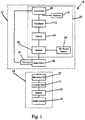
- the inductive power supply system 10 generally includes an adaptive inductive power supply (“AIPS") 12 and one of a plurality of remote devices 14.
- the AIPS 12 generally includes a tank circuit 48 with a primary coil 18 (See Fig. 2 ) capable of inductively transmitting power.
- the AIPS also includes a controller 20 for selectively controlling the frequency at which power is generated by the primary coil 18, and a sensor 16 capable of sensing reflected impedance from a remote device 14.
- the AIPS 12 is intended for use with one or more remote devices 14, each of which has a unique resonant frequency or unique pattern of resonant frequencies.
- the AIPS 12 applies power to the primary 18 at an identification frequency and then evaluates the reflected impendence of the remote device 14 using the current sensor 16. If the remote device 14 has a resonant frequency at the identification frequency, then the AlPS 12 knows what type of remote device is inductively coupled to AIPS 12 and the AlPS 12 can recover operating parameters from a look-up table or other memory device. The recovered information can be used by the AIPS to provide efficient operation of the remote device and to identify fault conditions.
- adaptive inductive power supply is intended to broadly include any inductive power supply capable of providing power at a plurality of different frequencies.
- the present invention is described in connection with a particular AIPS 12.
- the illustrated AIPS 12 is merely exemplary, however, and the present embodiment, not covered by the appended claims, may be implemented with essentially any AIPS capable of providing inductive power at varying frequencies.
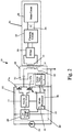
- the AlPS 12 generally includes a frequency controller 20 and a tank circuit 48.
- the frequency controller 20 applies power to the tank circuit 48 to generate a source of electromagnetic inductive power.
- the frequency controller 20 of the illustrated embodiment, not covered by the appended claims generally includes a microcontroller 40, an oscillator 42, a driver 44 and an inverter 46.
- the microcontroller 40 may be a microcontroller, such as a PIC1 8LF1 320, or a more general purpose microprocessor.
- the oscillator 42 and driver 44 may be discrete components or they may be incorporated into the microcontroller 40, for example, in the embodiment, not covered by the appended claims, illustrated in Fig.
- the oscillator 42 is a module within the microcontroller 40.
- the frequency controller 20 may also include a low voltage power supply 26 for supplying low voltage power to the microprocessor 40 and the driver 44.
- the various components of the frequency controller 20 collectively drive the tank circuit 48 at a frequency dictated by the microcontroller 40. More specifically, the microcontroller 40 sets the timing of the oscillator 42.
- the microprocessor 40 may establish the operating frequency as a function of input from the current sensor 16.
- the oscillator 42 operates the driver 44 at the frequency established by the microcontroller 40.
- the driver 44 provides the signals necessary to operate the switches 47a-b within the inverter 46. As a result, the inverter 46 provides AC (alternating current) power to the tank circuit 48 from a source of DC (direct current) power 50.
- the current sensor 16 is a current transformer having its primary coil disposed in the tank circuit 48 and its secondary coil connected to the microcontroller 40.
- the AIPS may include conditioning circuitry 28 for conditioning the current transformer output before it is supplied to the microcontroller 40.
- the illustrated embodiment includes a current transformer for sensing the reflected impedance of the remote device
- the AIPS 12 may include essentially any alternative type of sensor capable of providing information regarding reflected impedance from the remote device 14.
- the current sensor 16 of the illustrated embodiment is located in the tank circuit, the current sensor (or other reflected impedance sensor) can be located in essentially any location where it is capable of providing readings indicative of the presence or absence of resonance in the remote device.
- the AIPS further includes a lookup table 24 or other memory device capable of storing information relating to the operating parameters of a plurality of remote devices 14. The stored information may be used to permit the AIPS 12 to more efficiently power the remote device 14 and more readily recognize fault conditions.
- the AIPS 12 may be intended for use with a specific set of remote devices 14.
- the lookup table 24 includes the unique resonant frequency (or pattern of frequencies) for each remote device 14, along with the desired collection of associated information, such as maximum and minimum operating frequencies and current usage.
- the lookup table 24 may, however, include essentially any information that may be useful to the AIPS 12 in operating the remote device 14. For example, in applications where it is desirable to establish wireless communications with the remote device 14, the lookup table 24 may include information regarding the wireless communication protocol of the remote device 14.
- the tank circuit 48 generally includes the primary coil 18 and a capacitor 52.
- the capacitance of capacitor 52 may be selected to balance the impedance of the primary coil 18 at anticipated operating parameters.
- the tank circuit 48 may be either a series resonant tank circuit (as shown) or a parallel resonant tank circuit (not shown).
- the present embodiment, not covered by the appended claims, may be incorporated into the AIPS shown in U.S. Patent 6,825,620 .
- the present embodiment, not covered by the appended claims may be incorporated into the AIPS shown in U.S. Patent Application Publication US 2004/130916A1 to Baarman , which is entitled "Adapted Inductive Power Supply” and was published on July 8, 2004 ( U.S. Serial No.
- the present invention is intended for use with a wide variety of remote devices of varying designs and constructions. It is anticipated that these various remote devices will require power at varying frequency and will have different current requirements.
- the remote device may inherently include a unique resonant frequency or pattern of resonant frequencies.
- a specific type of remote device may include a resonant frequency at 195 kHz. If none of the other remote devices to be identified by the AIPS include a resonant frequency at 195 kHz, then 195 kHz can operate as the identification frequency for this type of remote device.
- the remote device does not include a resonant frequency that is unique among the set of remote devices that may need to be identified, then it may be possible to use the presence of a unique pattern of resonant frequencies to identify the remote device.
- a remote device may have one resonant frequency at 195 kHz and another resonant frequency at 215 kHz. Even if other remote devices have a resonant frequency at 195 kHz or at 215 kHz, the combination of the two resonant frequencies in a single type of remote device may be sufficient to uniquely identify the type of remote device. If two resonant frequencies are not sufficient to uniquely identify a type of remote devices, then even more resonant frequencies may be considered until a unique pattern of identification frequencies emerges.
- the present invention shows a remote device 14 having an inherent identification frequency is shown in Fig. 2 .
- the remote device 14 generally includes a secondary coil 22 for receiving power from the AIPS 12, a bridge 30 (or other rectifier for converting AC power to DC), a charging circuit 32, a battery 34 and a main circuit 36.
- the bridge 30 converts the AC power generated in the secondary 22 to DC power, which is required for operation of charging circuit 32 in this embodiment.
- Charging circuits are well-known and are widely used with a variety of rechargeable electronic devices. If desired, the charging circuit 32 may be configured to both charge the battery 34 and/or power the remote device 14 (if the remote device 14 is powered on).
- the charging circuit 32 will be a part of the main circuit 36. In other applications, the charging circuit 32 will be a separate circuit, and may even be controlled by the AIPS 12, if desired.
- the term "main circuit" is used loosely to refer to the operating circuitry for the remote device 14.
- the illustrated embodiment is described in connection with a battery-powered remote device, one example, not covered by the appended claims, may alternatively be used to directly power a remote device by eliminating the battery 34 and charging circuit 32 and connecting the secondary 22 to the main circuit 36, for example, through appropriate power conditioning circuitry, which may include a transformer or rectifier (such as bridge 30).
- appropriate power conditioning circuitry which may include a transformer or rectifier (such as bridge 30).
- a remote device may be provided with one or more identification capacitors that provide resonance at desired identification frequencies. Although useable with all remote devices, this embodiment is perhaps most useful with remote devices that do not have an inherent identification frequency or inherent identification pattern of frequencies.
- Fig. 3A shows a circuit diagram of an exemplary remote device 14' having an identification capacitor 38'. As shown in Fig. 3 A , an identification capacitor 38' is connected in parallel across the secondary 22'. The identification capacitor 38' has a capacitance selected to establish resonance at the identification frequency. In the present invention, it is possible that the charging circuit 32' and/or the main circuit 36' will mask the identification capacitor 38' making it difficult or impossible for the AlPS 12 to recognize the presence of the identification capacitor 38'.
- the remote device 14' includes a load enable delay circuit 54' that prevents the charging circuit 32' and/or the main circuit 36' from receiving power for a period of time sufficient for the identification capacitor 38' to establish resonance and for that resonance to be conveyed to the AIPS 12 through reflected impedance.
- the load enable delay circuit 54' may include a simple timed switching circuit that connects the bridge 30' to the charging circuit 32' only after a sufficient period of time has lapsed.
- This embodiment is particularly well-suited for incorporating the present invention into remote devices already including a charging circuit.
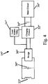
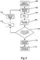
- Fig. 4 shows an alternative embodiment intended primarily for use in incorporating the present invention into remote devices not already including charging circuitry or that include charging circuitry having a microprocessor with an enable input.
- the load enable delay 54''' is connected to the "enable" input of the microprocessor in the charging circuitry 32'''. In this embodiment, the load enable delay 54''' does not enable the charging circuitry 32''' until a sufficient amount of time has passed for the AIPS 12 to recognize whether or not the identification capacitor 38''' has established resonance.
- the load enable delay circuit may be essentially any circuitry capable of preventing the charging circuit and/or main circuit from masking the identification capacitor long enough for the AIPS 12 to recognize whether resonance has been established.
- the remote device 14' includes only a single identification capacitor 38'.
- the remote device 14" is provided with three identification capacitors 38a-c" connected in parallel to the load each providing resonance at a different frequency.
- additional identification capacitors can be provided to establish even more additional resonant frequencies, if desired.
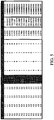
- Fig. 5 is a table showing the resonance frequencies that may be provided using different combinations of four capacitors. The first four columns labeled C1-C4 list the capacitance (in microfarads) of four different capacitors. In this example, the capacitors are 8.2, 6.8, 3.3, and 2.2 microfarad capacitors.
- the second four columns labeled C1-C4 identify the capacitors included that particular combination, using a "1" to represent the presence of a capacitor and a "0" to represent the absence of a capacitor.
- the column labeled “Capacitance” provides the combined capacitance of the capacitors in that particular combination.
- the column labeled “Frequency” provides the resonant frequency of the capacitor combination when the inductance is 0.000000309 as specified in the last column.
- row four includes a "1" in the C1 and C2 columns to indicate that an 8.2 microfarad capacitor and a 6.8 microfarad capacitor are combined to provide a combined capacitance of 3.7173 microfarad, which will have a resonant frequency of roughly 148.5 kHz.
- the identification capacitors will also establish resonance at the individual capacitances of each capacitor in that combination. So, continuing with the row 4 example, the combined capacitors will also have a resonant frequency at roughly 100 kHz (the resonance frequency of the 8.2 microfarad capacitor) and at roughly 109.9 kHz (the resonance frequency of the 6.8 microfarad capacitor).
- the combination of 8.2 and 6.8 microfarad capacitors provides an identification frequency pattern with resonance at roughly 100 kHz, 109.9 kHz and 148.5 kHz.
- the system 10 is configured to recognize one of a plurality of remote devices.
- Each remote device includes a single resonant frequency that is unique among the remote devices.
- the AIPS 12 can uniquely identify a remote device by cycling through each of the potential identification frequencies until a remote device is present that establishes resonance at one of the potential identification frequencies.
- the AIPS 12 is provided with data defining a plurality of potential identification frequencies.
- a list or table of potential identification frequencies may be stored in onboard memory on the microcontroller 40.
- the identification process begins by setting 100 the identification frequency to the first frequency in the list.
- the AIPS 12 then applies 102 power to the tank circuit 48 at the identification frequency.
- the AIPS 12 continues to apply power to the tank circuit 48 for a period of delay 104.
- the delay period is selected to provide sufficient time for the remote device 14 to establish resonance and to generate sufficient reflected impedance in the tank circuit 48.
- the delay period may be a fixed period of time that remains constant throughout the identification process.
- the delay period may vary from application to application, but in the illustrated embodiment is approximately 6 microseconds.
- a sufficient delay may be inherent in the system and therefore may not require the implementation of a separate deliberate delay step. If the remote device 14 includes a resonant frequency at the identification frequency, the remote device 14 will draw current and this increase in current draw will be reflected back into the tank circuit 48 by reflected impedance. After the delay 104 is complete, the microprocessor 40 obtains 106 input from the current sensor 16. As noted above, the output of the current sensor 16 may be conditioned using conditioning circuitry 28. The microprocessor 40 evaluates the input from the current sensor 16 to determine whether the remote device 14 has a resonant frequency at the current identification frequency. In this embodiment, the microprocessor 40 will conclude that a resonant frequency exists if the current sensor reading is above a threshold value. Typically, the threshold value for a specific application will be a value above the noise floor of that application plus an additional deadband. The amount of the deadband may vary from application to application.
- the controller 20 prepares to apply to the next identification frequency to the tank circuit 48. More specifically, the microprocessor 40 enters a delay 114 for a relatively short period of time.
- the delay period is selected to provide sufficient time for the remote device 14 to settle and for the energy in the remote device 14 to sufficiently dissipate.
- the delay period may be a fixed period of time that remains constant from throughout the identification process.
- the settle delay period may vary from application to application, but in the illustrated embodiment is approximately 5 microseconds. In some applications, a sufficient delay may be inherent in the system and therefore may not require the implementation of a separate deliberate settle delay step.
- the microprocessor 40 sets the identification frequency as the next frequency in the list of potential identification frequencies. The process then repeats beginning with the step of applying 102 power to the tank circuit 48 at the new identification frequency.
- the microprocessor 40 determines that the remote device 14 includes a resonant frequency at the current identification frequency, the microprocessor 40 will retrieve 110 the operating parameters from the lookup table 24 and will exit the remote device identification process. The microprocessor 40 may then operate 1 12 the remote device 14 using the operating parameters retrieved from lookup table 24.
- the lookup table 24 may include an anticipated operating frequency and may begin operation by applying power to the tank circuit 48 at the recalled operating frequency.
- the microprocessor 40 may also use maximum and minimum current draws values obtained from the lookup table to determine the presence of a fault condition. For example, if during operation the actual current draw sensed by the current sensor exceeds the maximum current draw or falls below the minimum current draw, the microprocessor 40 will conclude that a fault condition exists.
- the microprocessor 40 may be programmed to take remedial action if a fault condition is encountered. For example, the microprocessor 40 may be programmed to shut down the system if a fault condition arises. Alternatively, the microprocessor 40 may restart the identification process to determine if a different remote device 40 has been placed near the primary 18.
- the microprocessor 40 cycles through a list of potential identification frequencies in an effort to identify a remote device.
- the AIPS 12 may be programmed to simply cycle through a range of frequencies using a specified step value. For example, by stepping from 100 kHz to 300kHz in 5 kHz increments.
- an embodiment of the disclosure provides a mechanism for establishing standards for using frequency identification for remote devices.
- unique identification frequencies can be specified for each type of remote device and for other identifying features.
- the standards may specify a different identification frequency for each type of device (e.g. cell phone, personal digital assistant, may digital music player) and/or for each manufacturer (e.g. company name).
- the manufacturer may be permitted to add additional identification frequencies to specify model numbers and product types.
- identification frequencies are stablished by the class of the remote device rather than the specific model type. For example, all devices operating within a given set of operating parameters can be assigned the same identification frequency (or identification frequency pattern).
- This alternative method is particularly well-suited for use in application where a plurality of remote devices of different types are capable of operating under the operating parameters set forth in a single record in the lookup table.
- each device capable of being inductively powered or charged by an inductive power supply is provided with at least one common resonant frequency, and at least one unique frequency.
- each device capable of being charged by AlPS 12 is provided with an 8.2 microfarad capacitor, providing the device with a primary identification resonant frequency of 100 kHz.
- AIPS 12 repeatedly sends out a pulse at approximately 100 kHz. If a device 14 with a resonant frequency of 100 kHz is placed within the field generated by AIPS 12, then AlPS proceeds with a sweep of additional frequencies to identify the type of device 14.
- the charging circuit of each individual battery type is provided with a second unique resonant frequency, or secondary identification frequency.
- each lithium ion battery is further comprised of a capacitor or other circuitry to provide a secondary resonant frequency at 109.4 kHz; each nickel cadmium battery is provided with a capacitor or other circuitry to provide a secondary resonant frequency at 148.5 kHz.
- each battery may further equipped with a capacitor or other circuitry to provide a tertiary resonant frequency used to identify the individual manufacturer or supplier of that battery.
- each inductively charged lithium ion battery manufactured or sold by vendor X is provided with one or more capacitors or other circuitry to provide a primary identification resonant frequency of 100kHz, a secondary identification resonant frequency of 109.4 kHz, and a tertiary identification resonant frequency of 130 kHz.
- Each lithium ion battery manufactured or sold by vendor Y is provided with one or more capacitors or other circuitry to provide a primary identification resonant frequency of 100kHz, a secondary identification resonant frequency of 109.4 kHz, and a tertiary identification resonant frequency of 140 kHz.
- an additional identification resonant frequency may be added to distinguish, for example, different types of inductively charged lithium ion batteries sold by vendor X or vendor Y.
- identification could allow AIPS to adjust the charging or power control not only according to the requirements of various load types as discussed above, but according to specific requirements of individual manufacturers or suppliers of those load types. It would be obvious that such identification strategies and protocols could be used to identify inductive loads that are not only powered by a rechargeable battery, but also to identify those loads that are directly inductively powered.
- the standards discussed above rely on the assignment of a range of identification frequencies.
- the spacing between identification frequencies may vary from application to application depending of the resolution of the AlPS sensing the present of resonance during the identification process. For example, an AIPS with sufficient resolution to accurately recognize frequency differences of 5 kHz can use a separation of 5 kHz between identification frequencies (e.g. 250 kHz and 255 kHz).
- An AlPS with lower resolution may require greater separation between identification frequencies (e.g. 250 kHz and 260kHz).
Landscapes
- Engineering & Computer Science (AREA)
- Computer Networks & Wireless Communication (AREA)
- Power Engineering (AREA)
- Signal Processing (AREA)
- Physics & Mathematics (AREA)
- General Physics & Mathematics (AREA)
- Near-Field Transmission Systems (AREA)
- Charge And Discharge Circuits For Batteries Or The Like (AREA)
- Dc-Dc Converters (AREA)
- Remote Monitoring And Control Of Power-Distribution Networks (AREA)
- Selective Calling Equipment (AREA)
Applications Claiming Priority (4)
| Application Number | Priority Date | Filing Date | Title |
|---|---|---|---|
| US88312707P | 2007-01-02 | 2007-01-02 | |
| US11/965,085 US7989986B2 (en) | 2006-03-23 | 2007-12-27 | Inductive power supply with device identification |
| EP07859543.6A EP2118813B1 (en) | 2007-01-02 | 2007-12-28 | Inductive power supply with device identification |
| PCT/IB2007/055339 WO2008081405A1 (en) | 2007-01-02 | 2007-12-28 | Inductive power supply with device identification |
Related Parent Applications (1)
| Application Number | Title | Priority Date | Filing Date |
|---|---|---|---|
| EP07859543.6A Division EP2118813B1 (en) | 2007-01-02 | 2007-12-28 | Inductive power supply with device identification |
Publications (2)
| Publication Number | Publication Date |
|---|---|
| EP3640836A1 EP3640836A1 (en) | 2020-04-22 |
| EP3640836B1 true EP3640836B1 (en) | 2021-05-05 |
Family
ID=39582870
Family Applications (2)
| Application Number | Title | Priority Date | Filing Date |
|---|---|---|---|
| EP19209332.6A Active EP3640836B1 (en) | 2007-01-02 | 2007-12-28 | Inductive power supply with device identification |
| EP07859543.6A Active EP2118813B1 (en) | 2007-01-02 | 2007-12-28 | Inductive power supply with device identification |
Family Applications After (1)
| Application Number | Title | Priority Date | Filing Date |
|---|---|---|---|
| EP07859543.6A Active EP2118813B1 (en) | 2007-01-02 | 2007-12-28 | Inductive power supply with device identification |
Country Status (14)
| Country | Link |
|---|---|
| US (4) | US7989986B2 (enExample) |
| EP (2) | EP3640836B1 (enExample) |
| JP (2) | JP5180228B2 (enExample) |
| KR (3) | KR101731503B1 (enExample) |
| CN (2) | CN103457363B (enExample) |
| AU (1) | AU2007340951B2 (enExample) |
| CA (1) | CA2674103A1 (enExample) |
| ES (1) | ES2875973T3 (enExample) |
| HU (1) | HUE055217T2 (enExample) |
| MY (1) | MY151398A (enExample) |
| NZ (1) | NZ577900A (enExample) |
| RU (1) | RU2464632C2 (enExample) |
| TW (1) | TWI459678B (enExample) |
| WO (1) | WO2008081405A1 (enExample) |
Families Citing this family (154)
| Publication number | Priority date | Publication date | Assignee | Title |
|---|---|---|---|---|
| US7355150B2 (en) | 2006-03-23 | 2008-04-08 | Access Business Group International Llc | Food preparation system with inductive power |
| US7989986B2 (en) * | 2006-03-23 | 2011-08-02 | Access Business Group International Llc | Inductive power supply with device identification |
| US11245287B2 (en) | 2006-03-23 | 2022-02-08 | Philips Ip Ventures B.V. | Inductive power supply with device identification |
| CA2709860A1 (en) * | 2007-12-21 | 2009-07-02 | Access Business Group International Llc | Inductive power transfer |
| TWI488400B (zh) * | 2008-03-13 | 2015-06-11 | Access Business Group Int Llc | 具有多重線圈之初級線圈的感應式電源供應系統及其感應式電源供應器與方法 |
| JP2009268181A (ja) * | 2008-04-22 | 2009-11-12 | Olympus Corp | エネルギー供給装置 |
| US8981598B2 (en) | 2008-07-02 | 2015-03-17 | Powermat Technologies Ltd. | Energy efficient inductive power transmission system and method |
| US9473209B2 (en) * | 2008-08-20 | 2016-10-18 | Intel Corporation | Wireless power transfer apparatus and method thereof |
| JP4911148B2 (ja) * | 2008-09-02 | 2012-04-04 | ソニー株式会社 | 非接触給電装置 |
| CN101667752A (zh) * | 2008-09-04 | 2010-03-10 | 洪长安 | 无线耦合共振磁电传送器 |
| AU2009298384A1 (en) * | 2008-10-03 | 2010-04-08 | Access Business Group International Llc | Power system |
| ES2779011T3 (es) | 2008-11-07 | 2020-08-13 | Toyota Motor Co Ltd | Sistema de alimentación de energía para vehículos y vehículo de tracción eléctrica |
| JP5441392B2 (ja) * | 2008-11-12 | 2014-03-12 | キヤノン株式会社 | 電子機器及び方法 |
| CN102215733B (zh) * | 2008-11-18 | 2014-06-18 | 奥林巴斯株式会社 | 胶囊型医疗装置、供电装置以及供电系统 |
| US8069100B2 (en) | 2009-01-06 | 2011-11-29 | Access Business Group International Llc | Metered delivery of wireless power |
| WO2010079768A1 (ja) * | 2009-01-08 | 2010-07-15 | Necトーキン株式会社 | 電力送信装置及び非接触電力伝送システム |
| US9407327B2 (en) * | 2009-02-13 | 2016-08-02 | Qualcomm Incorporated | Wireless power for chargeable and charging devices |
| WO2010116441A1 (ja) | 2009-03-30 | 2010-10-14 | 富士通株式会社 | 無線電力供給システム、無線送電装置、および無線受電装置 |
| JP5515368B2 (ja) * | 2009-03-31 | 2014-06-11 | 富士通株式会社 | 無線電力供給方法及び無線電力供給システム |
| US8536736B2 (en) * | 2009-04-03 | 2013-09-17 | International Business Machines Corporation | Wireless power infrastructure |
| JP2010252468A (ja) * | 2009-04-14 | 2010-11-04 | Sony Corp | 送電装置および方法、受電装置および方法、並びに、電力伝送システム |
| US7847664B2 (en) * | 2009-05-06 | 2010-12-07 | Verde Power Supply, Inc. | Electromagnetic apparatus using shared flux in a multi-load parallel magnetic circuit and method of operation |
| US8853995B2 (en) * | 2009-06-12 | 2014-10-07 | Qualcomm Incorporated | Devices for conveying wireless power and methods of operation thereof |
| US20100327824A1 (en) * | 2009-06-30 | 2010-12-30 | Richard Dellacona | Power supply using shared flux in a multi-load parallel magnetic circuit |
| RU2540896C2 (ru) * | 2009-07-24 | 2015-02-10 | Эксесс Бизнесс Груп Интернешнл Ллс | Источник питания |
| US9312728B2 (en) | 2009-08-24 | 2016-04-12 | Access Business Group International Llc | Physical and virtual identification in a wireless power network |
| KR101679580B1 (ko) | 2009-10-16 | 2016-11-29 | 삼성전자주식회사 | 무선 전력 전송 장치, 무선 전력 전송 제어 장치 및 그 방법 |
| US8547057B2 (en) * | 2009-11-17 | 2013-10-01 | Qualcomm Incorporated | Systems and methods for selective wireless power transfer |
| JP2011147271A (ja) * | 2010-01-14 | 2011-07-28 | Sony Corp | 給電装置、受電装置、およびワイヤレス給電システム |
| JP5051257B2 (ja) | 2010-03-16 | 2012-10-17 | トヨタ自動車株式会社 | 車両 |
| JP5691458B2 (ja) * | 2010-03-31 | 2015-04-01 | 日産自動車株式会社 | 非接触給電装置及び非接触給電方法 |
| WO2011127334A2 (en) | 2010-04-08 | 2011-10-13 | Access Business Group International Llc | Point of sale inductive systems and methods |
| US9365104B2 (en) | 2010-04-21 | 2016-06-14 | Toyota Jidosha Kabushiki Kaisha | Parking assist device for vehicle and electrically powered vehicle including the same |
| US8841881B2 (en) | 2010-06-02 | 2014-09-23 | Bryan Marc Failing | Energy transfer with vehicles |
| CN102299569B (zh) | 2010-06-24 | 2014-08-13 | 海尔集团公司 | 无线供电系统及其自适应调整方法 |
| JP2012023913A (ja) * | 2010-07-16 | 2012-02-02 | Shigeo Hamaguchi | 非接触給電装置 |
| WO2012014787A1 (en) * | 2010-07-28 | 2012-02-02 | Semiconductor Energy Laboratory Co., Ltd. | Wireless power feeding system and wireless power feeding method |
| JP5538124B2 (ja) * | 2010-08-03 | 2014-07-02 | 三洋電機株式会社 | 電池内蔵機器の無接点充電方法 |
| JP5543881B2 (ja) * | 2010-09-16 | 2014-07-09 | 株式会社東芝 | 無線電力伝送装置 |
| US9219378B2 (en) | 2010-11-01 | 2015-12-22 | Qualcomm Incorporated | Wireless charging of devices |
| US9536655B2 (en) * | 2010-12-01 | 2017-01-03 | Toyota Jidosha Kabushiki Kaisha | Wireless power feeding apparatus, vehicle, and method of controlling wireless power feeding system |
| US9231412B2 (en) | 2010-12-29 | 2016-01-05 | National Semiconductor Corporation | Resonant system for wireless power transmission to multiple receivers |
| DE102011003516A1 (de) * | 2011-02-02 | 2012-08-02 | Osram Ag | Energiebox mit induktivem Ladegerät sowie Verfahren zum Laden einer Energiebox |
| US8946939B2 (en) * | 2011-03-31 | 2015-02-03 | Qualcomm Incorporated | Systems and methods for detecting and protecting a wireless power communication device in a wireless power system |
| US20120290470A1 (en) * | 2011-05-11 | 2012-11-15 | Samsung Electro-Mechanics Company, Ltd. | Payment systems and methods for providing wireless power transfer |
| KR102000987B1 (ko) | 2011-05-17 | 2019-07-17 | 삼성전자주식회사 | 다중 무선 전력 전송을 수행하기 위한 전력 송수신 장치 및 방법 |
| KR101241495B1 (ko) * | 2011-06-08 | 2013-03-11 | 엘지이노텍 주식회사 | 무선 전력 송신 장치 및 그의 무선 전력 송신 방법 |
| WO2013046209A2 (en) * | 2011-09-30 | 2013-04-04 | Powermat Technologies Ltd. | Inductive power transmission |
| KR101349551B1 (ko) * | 2011-11-02 | 2014-01-08 | 엘지이노텍 주식회사 | 무선 전력 송신 장치 및 그 방법 |
| GB2511448B (en) * | 2011-11-24 | 2017-10-04 | Murata Manufacturing Co | Power transmission device and power transmission control method |
| KR101254092B1 (ko) * | 2011-12-21 | 2013-04-12 | 주식회사 스파콘 | 신호 검출장치 및 이를 구비한 무선 전력전송장치 |
| WO2013098016A1 (en) * | 2011-12-29 | 2013-07-04 | Arcelik Anonim Sirketi | Wireless kitchen appliance operated on an induction heating cooker |
| EP2798909B1 (en) | 2011-12-29 | 2017-04-05 | Arçelik Anonim Sirketi | Wireless kitchen appliance operated on induction heating cooker |
| CN104025468B (zh) | 2012-01-08 | 2016-11-02 | 捷通国际有限公司 | 用于多个感应系统的干扰缓解 |
| KR102185160B1 (ko) * | 2012-05-02 | 2020-12-02 | 애플 인크. | 유도선 전력 전송 시스템에서 수신기를 탐지하고 식별하기 위한 방법들 |
| US9696358B2 (en) | 2012-05-02 | 2017-07-04 | Powerbyproxi Limited | Method for detecting and identifying a receiver in an inductive power transfer system |
| WO2013164831A1 (en) * | 2012-05-03 | 2013-11-07 | Powermat Technologies Ltd. | System and method for triggering power transfer across an inductive power coupling and non resonant transmission |
| GB2503442A (en) | 2012-06-26 | 2014-01-01 | Ibm | Locating faults in a network |
| DE102012213363A1 (de) * | 2012-07-30 | 2014-01-30 | Siemens Aktiengesellschaft | Dockingstation für eine kabellose Energie- und Datenanbindung |
| US9859744B2 (en) * | 2012-08-03 | 2018-01-02 | Mediatek Singapore Pte. Ltd. | Dual-mode wireless power receiver |
| US9912197B2 (en) * | 2012-08-03 | 2018-03-06 | Mediatek Singapore Pte. Ltd. | Dual-mode wireless power receiver |
| US10658869B2 (en) | 2012-08-03 | 2020-05-19 | Mediatek Inc. | Multi-mode, multi-standard wireless power transmitter coil assembly |
| US9385557B2 (en) | 2012-08-23 | 2016-07-05 | At&T Mobility Ii Llc | Methods, systems, and products for charging of devices |
| CN110098642A (zh) * | 2012-11-05 | 2019-08-06 | 苹果公司 | 感应耦合电力传输系统 |
| CN202995349U (zh) * | 2012-12-26 | 2013-06-12 | 黄冠雄 | 微功耗待机系统及厚膜混合集成电路模块 |
| JP6164857B2 (ja) * | 2013-02-12 | 2017-07-19 | キヤノン株式会社 | 給電装置、給電装置の制御方法、受電装置、受電装置の制御方法、プログラム |
| US9608513B2 (en) * | 2013-03-15 | 2017-03-28 | General Electric Company | Methods and systems for improving load transient response in LLC converters |
| CA2908452C (en) * | 2013-03-29 | 2016-06-07 | Nissan Motor Co., Ltd. | Non-contact power supply system |
| CN104124996B (zh) * | 2013-04-28 | 2018-08-14 | 海尔集团技术研发中心 | 实现无线电能传输系统无线通信的方法及系统 |
| CN104124765B (zh) * | 2013-04-28 | 2018-02-16 | 海尔集团技术研发中心 | 无线电能传输系统的功率调节方法及系统 |
| WO2015009350A1 (en) | 2013-07-16 | 2015-01-22 | Leeo, Inc. | Electronic device with environmental monitoring |
| US9116137B1 (en) | 2014-07-15 | 2015-08-25 | Leeo, Inc. | Selective electrical coupling based on environmental conditions |
| CN103427501B (zh) * | 2013-08-19 | 2015-06-17 | 重庆大学 | 一种电压型无线供电系统负载识别方法及系统 |
| TWI594191B (zh) * | 2013-08-26 | 2017-08-01 | 緯創資通股份有限公司 | 識別系統、實體裝置、識別裝置及實體裝置的識別方法 |
| US9792622B2 (en) * | 2013-09-05 | 2017-10-17 | Avago Technologies General Ip (Singapore) Pte. Ltd. | Communicating device data prior to establishing wireless power connection |
| US20150091508A1 (en) * | 2013-10-01 | 2015-04-02 | Blackberry Limited | Bi-directional communication with a device under charge |
| WO2015064815A1 (ko) * | 2013-10-31 | 2015-05-07 | 주식회사 한림포스텍 | 하이브리드 무선 전력 전송 시스템 및 그 방법 |
| JP6315382B2 (ja) * | 2013-12-19 | 2018-04-25 | パナソニックIpマネジメント株式会社 | 無線電力伝送のための送電装置および受電装置ならびに無線電力伝送システム |
| US20170324270A1 (en) * | 2013-12-26 | 2017-11-09 | Calvin Shie-Ning Wang | Standby circuit, and outlet, plug, and device having the same |
| EP3095169A4 (en) * | 2014-01-19 | 2017-10-25 | Powermat Technologies Ltd. | Wireless power outlet and method of transferring power thereby |
| US9995777B2 (en) * | 2014-02-14 | 2018-06-12 | Qualcomm Incorporated | Device detection through dynamic impedance change measurement |
| US9716861B1 (en) | 2014-03-07 | 2017-07-25 | Steelcase Inc. | Method and system for facilitating collaboration sessions |
| US10664772B1 (en) | 2014-03-07 | 2020-05-26 | Steelcase Inc. | Method and system for facilitating collaboration sessions |
| US9874914B2 (en) * | 2014-05-19 | 2018-01-23 | Microsoft Technology Licensing, Llc | Power management contracts for accessory devices |
| US9766079B1 (en) | 2014-10-03 | 2017-09-19 | Steelcase Inc. | Method and system for locating resources and communicating within an enterprise |
| US9380682B2 (en) | 2014-06-05 | 2016-06-28 | Steelcase Inc. | Environment optimization for space based on presence and activities |
| US9955318B1 (en) | 2014-06-05 | 2018-04-24 | Steelcase Inc. | Space guidance and management system and method |
| US11744376B2 (en) | 2014-06-06 | 2023-09-05 | Steelcase Inc. | Microclimate control systems and methods |
| US10614694B1 (en) | 2014-06-06 | 2020-04-07 | Steelcase Inc. | Powered furniture assembly |
| US10433646B1 (en) | 2014-06-06 | 2019-10-08 | Steelcaase Inc. | Microclimate control systems and methods |
| JP6381305B2 (ja) | 2014-06-10 | 2018-08-29 | キヤノン株式会社 | 電子機器 |
| US10135305B2 (en) | 2014-06-10 | 2018-11-20 | Mediatek Singapore Pte. Ltd. | Multi-mode wireless power transmitter |
| US9717006B2 (en) | 2014-06-23 | 2017-07-25 | Microsoft Technology Licensing, Llc | Device quarantine in a wireless network |
| US9372477B2 (en) | 2014-07-15 | 2016-06-21 | Leeo, Inc. | Selective electrical coupling based on environmental conditions |
| WO2016009513A1 (ja) * | 2014-07-16 | 2016-01-21 | 富士機械製造株式会社 | 非接触給電装置 |
| WO2016010772A2 (en) * | 2014-07-17 | 2016-01-21 | The University Of Florida Research Foundation, Inc. | Wireless power transfer using one or more rotating magnets in a receiver |
| US9489549B2 (en) * | 2014-08-05 | 2016-11-08 | Minipumps, Llc | Implant telemetry with dynamic tuning |
| US9092060B1 (en) | 2014-08-27 | 2015-07-28 | Leeo, Inc. | Intuitive thermal user interface |
| US10078865B2 (en) | 2014-09-08 | 2018-09-18 | Leeo, Inc. | Sensor-data sub-contracting during environmental monitoring |
| US9852388B1 (en) | 2014-10-03 | 2017-12-26 | Steelcase, Inc. | Method and system for locating resources and communicating within an enterprise |
| US9445451B2 (en) | 2014-10-20 | 2016-09-13 | Leeo, Inc. | Communicating arbitrary attributes using a predefined characteristic |
| US10026304B2 (en) | 2014-10-20 | 2018-07-17 | Leeo, Inc. | Calibrating an environmental monitoring device |
| JP6213485B2 (ja) * | 2014-11-28 | 2017-10-18 | トヨタ自動車株式会社 | 送電装置 |
| JP6013437B2 (ja) * | 2014-12-05 | 2016-10-25 | 本田技研工業株式会社 | 非接触充電器 |
| JP2016127740A (ja) * | 2015-01-06 | 2016-07-11 | 東芝テック株式会社 | 情報処理装置及び周辺機器 |
| CN104753131B (zh) * | 2015-02-16 | 2016-02-24 | 郑州携能通信技术有限公司 | 一种无线充电方法及系统 |
| KR102398958B1 (ko) * | 2015-04-27 | 2022-05-17 | 삼성전자주식회사 | 무선 전력 수신 장치 |
| US10733371B1 (en) | 2015-06-02 | 2020-08-04 | Steelcase Inc. | Template based content preparation system for use with a plurality of space types |
| US9425644B1 (en) | 2015-06-03 | 2016-08-23 | Thor Charger Company | Method and apparatus for charging an electrically chargeable device utilizing resonating magnetic oscillations in the apparatus |
| US9801013B2 (en) | 2015-11-06 | 2017-10-24 | Leeo, Inc. | Electronic-device association based on location duration |
| US10805775B2 (en) | 2015-11-06 | 2020-10-13 | Jon Castor | Electronic-device detection and activity association |
| US12507009B2 (en) | 2015-11-19 | 2025-12-23 | The Lovesac Company | Systems and methods for correcting sound loss through partially acoustically transparent materials |
| US10212519B2 (en) | 2015-11-19 | 2019-02-19 | The Lovesac Company | Electronic furniture systems with integrated internal speakers |
| US11689856B2 (en) | 2015-11-19 | 2023-06-27 | The Lovesac Company | Electronic furniture systems with integrated induction charger |
| CN108401471B (zh) * | 2015-11-19 | 2021-06-25 | 苹果公司 | 感应式电力发射器 |
| US20230209262A1 (en) | 2015-11-19 | 2023-06-29 | The Lovesac Company | Systems and methods for tuning based on furniture configuration |
| US10377469B2 (en) * | 2016-03-04 | 2019-08-13 | The Boeing Company | Non-contact power supply and data transfer on aerial vehicles |
| EP3435519B1 (en) * | 2016-03-25 | 2021-02-17 | Fuji Corporation | Wireless power supply device |
| US10218212B2 (en) * | 2016-04-15 | 2019-02-26 | The Gillette Company Llc | System and apparatus for inductive charging of a handheld device |
| US11234320B2 (en) * | 2016-05-30 | 2022-01-25 | Signify Holding B.V. | Switched mode power supply identification |
| US9921726B1 (en) | 2016-06-03 | 2018-03-20 | Steelcase Inc. | Smart workstation method and system |
| US10128698B2 (en) * | 2016-06-20 | 2018-11-13 | Hyundai America Technical Center, Inc | Device and method for detecting an object within a wireless charging region |
| JP6559348B2 (ja) * | 2016-06-30 | 2019-08-14 | 三菱電機株式会社 | 非接触電力伝送システム及び誘導加熱調理器 |
| US20180080999A1 (en) * | 2016-09-22 | 2018-03-22 | Qualcomm Incorporated | Determining power electronics feasibility with single turn magnetic simulation data |
| CN106487205B (zh) | 2016-09-23 | 2019-01-29 | 矽力杰半导体技术(杭州)有限公司 | 参数识别电路、方法及应用其的电源系统 |
| CN107919736A (zh) * | 2016-10-10 | 2018-04-17 | 三星电机株式会社 | 无线电力发送器 |
| KR101878135B1 (ko) * | 2016-11-23 | 2018-07-13 | 주식회사 아프로텍 | 용기 인증 기능을 구비한 유도 가열 장치 |
| CN106792017B (zh) * | 2016-12-09 | 2020-10-02 | 深圳Tcl数字技术有限公司 | 外设识别系统、方法及电子设备 |
| US10264213B1 (en) | 2016-12-15 | 2019-04-16 | Steelcase Inc. | Content amplification system and method |
| EP3346581B1 (en) * | 2017-01-04 | 2023-06-14 | LG Electronics Inc. | Wireless charger for mobile terminal in vehicle |
| KR101918229B1 (ko) * | 2017-01-04 | 2018-11-13 | 엘지전자 주식회사 | 차량에 구비되는 이동 단말기용 무선 충전 장치 및 차량 |
| JP7353178B2 (ja) * | 2017-03-07 | 2023-09-29 | パワーマット テクノロジーズ リミテッド | 無線電力充電用のシステム |
| EP3373414B1 (en) | 2017-03-07 | 2019-10-23 | Powermat Technologies Ltd. | System for wireless power charging |
| WO2018163169A1 (en) | 2017-03-07 | 2018-09-13 | Powermat Technologies Ltd. | System for wireless power charging |
| US11277030B2 (en) | 2017-03-07 | 2022-03-15 | Powermat Technologies Ltd. | System for wireless power charging |
| WO2019051026A2 (en) * | 2017-09-06 | 2019-03-14 | Zpower, Llc | SYSTEMS AND METHODS FOR WIRELESS LOAD |
| CN108599392B (zh) * | 2018-04-26 | 2021-07-09 | 青岛众海汇智能源科技有限责任公司 | 无线充电的方法、装置及计算机可读存储介质 |
| CN110568280A (zh) * | 2018-06-06 | 2019-12-13 | 上海国际汽车城(集团)有限公司 | 电动汽车无线充电系统原边器件参数偏移故障的诊断方法 |
| CN109102785B (zh) * | 2018-08-24 | 2020-11-13 | 北京晨语筝业教育科技有限公司 | 古筝演奏信息判断方法、演奏纠错方法及设备 |
| US10467836B1 (en) * | 2018-11-30 | 2019-11-05 | Hans Kirchhausen | Smart storage locker for mobile devices |
| US11011169B2 (en) | 2019-03-08 | 2021-05-18 | ROVl GUIDES, INC. | Inaudible frequency transmission in interactive content |
| US11074914B2 (en) | 2019-03-08 | 2021-07-27 | Rovi Guides, Inc. | Automated query detection in interactive content |
| US11522619B2 (en) | 2019-03-08 | 2022-12-06 | Rovi Guides, Inc. | Frequency pairing for device synchronization |
| US10956123B2 (en) | 2019-05-08 | 2021-03-23 | Rovi Guides, Inc. | Device and query management system |
| CN112394244B (zh) * | 2019-08-19 | 2021-09-14 | 广东美的白色家电技术创新中心有限公司 | 一种检测电路、电器及控制方法 |
| CN110474436B (zh) * | 2019-08-30 | 2021-08-24 | 维沃移动通信有限公司 | 一种无线充电方法及相关设备 |
| US12118178B1 (en) | 2020-04-08 | 2024-10-15 | Steelcase Inc. | Wayfinding services method and apparatus |
| US11280814B2 (en) * | 2020-04-08 | 2022-03-22 | General Electic Company | Systems and methods for wearable voltage sensing devices |
| US11277024B2 (en) | 2020-07-24 | 2022-03-15 | ZQ Power, LLC | Devices, systems, and methods for reducing standby power consumption |
| US11984739B1 (en) | 2020-07-31 | 2024-05-14 | Steelcase Inc. | Remote power systems, apparatus and methods |
| CA3189606A1 (en) | 2020-08-14 | 2022-02-17 | MTP Technologies, LLC | Cooking, soldering, and/or heating systems, and associated methods |
| CN214755753U (zh) * | 2021-05-13 | 2021-11-16 | 宁波微鹅电子科技有限公司 | 一种无线充电装置 |
| KR20230050042A (ko) * | 2021-10-07 | 2023-04-14 | 삼성전자주식회사 | 무선 전력 송신 장치 및 무선 전력 송신 장치에서 무선 전력 수신 장치 감지에 기반한 동작 모드 제어 방법 |
| KR20230111979A (ko) | 2022-01-19 | 2023-07-26 | 삼성전자주식회사 | 무선 전력 송신 장치, 무선 전력 수신 장치, 및 이의 동작 방법 |
Family Cites Families (70)
| Publication number | Priority date | Publication date | Assignee | Title |
|---|---|---|---|---|
| US3742178A (en) | 1971-12-29 | 1973-06-26 | Gen Electric | Induction cooking appliance including cooking vessel having means for wireless transmission of temperature data |
| US3761668A (en) * | 1972-03-01 | 1973-09-25 | Gen Electric | Small electrical apparatus powered by induction cooking appliances |
| GB2069299B (en) | 1980-01-30 | 1983-06-22 | Riccar Co Ltd | Induction heating apparatus |
| JPS6057666B2 (ja) * | 1980-01-30 | 1985-12-16 | リツカ−株式会社 | 誘導加熱調理器 |
| GB2197107B (en) | 1986-11-03 | 1990-12-12 | Mars Inc | Data-storing devices |
| FR2646049B1 (fr) | 1989-04-18 | 1991-05-24 | Cableco Sa | Plaque electrique chauffante amovible |
| RU2013842C1 (ru) * | 1991-07-09 | 1994-05-30 | Николай Алексеевич Шумаков | Система для заряда аккумуляторной батареи |
| JP2855929B2 (ja) | 1992-01-14 | 1999-02-10 | 松下電器産業株式会社 | コードレス機器 |
| JP3198628B2 (ja) | 1992-07-07 | 2001-08-13 | 松下電器産業株式会社 | コードレス機器 |
| DK0637898T3 (da) | 1994-05-24 | 1996-07-29 | Kolja Kuse | Køkkenbordplade med integreret kogefelt |
| DE4439095A1 (de) | 1994-11-02 | 1996-05-09 | Klaus Kozitzki | Verfahren und Vorrichtung zum Regeln der Kochstelle eines Kochfeldes |
| US5648008A (en) | 1994-11-23 | 1997-07-15 | Maytag Corporation | Inductive cooking range and cooktop |
| DE19502935A1 (de) | 1995-01-31 | 1996-08-01 | Ego Elektro Blanc & Fischer | Verfahren und Einrichtung zur Übermittlung von Daten von einem Kochgefäß zu einer Kocheinrichtung |
| WO1997034518A1 (en) | 1996-03-15 | 1997-09-25 | Aktiebolaget Electrolux | An apparatus for providing energy to kitchen appliances |
| JPH10234588A (ja) * | 1997-02-21 | 1998-09-08 | Haidetsuku Kk | 電磁誘導加熱装置 |
| JP3016732B2 (ja) * | 1996-04-24 | 2000-03-06 | ハイデック株式会社 | 電磁誘導加熱による熱放射加熱調理器 |
| US5821507A (en) | 1996-04-24 | 1998-10-13 | Hidec Co., Ltd. | Electric cooker using induction heater |
| SG54559A1 (en) | 1996-09-13 | 1998-11-16 | Hitachi Ltd | Power transmission system ic card and information communication system using ic card |
| JP3392016B2 (ja) * | 1996-09-13 | 2003-03-31 | 株式会社日立製作所 | 電力伝送システム並びに電力伝送および情報通信システム |
| JP3258247B2 (ja) | 1996-12-09 | 2002-02-18 | 象印マホービン株式会社 | 誘導加熱式炊飯器 |
| JPH10215530A (ja) | 1997-01-28 | 1998-08-11 | Matsushita Electric Works Ltd | 非接触電力伝送装置 |
| JPH11121159A (ja) | 1997-10-20 | 1999-04-30 | Toshiba Corp | 電磁調理器 |
| AT406805B (de) | 1998-02-06 | 2000-09-25 | Bse Mediscan Ges M B H & Co Kg | Verfahren zum behandeln eines gutes |
| JP2000295796A (ja) | 1999-04-02 | 2000-10-20 | Tokin Corp | 非接触電力供給装置 |
| JP3815115B2 (ja) | 1999-04-28 | 2006-08-30 | 松下電器産業株式会社 | 鍋材質識別器具 |
| US6825620B2 (en) | 1999-06-21 | 2004-11-30 | Access Business Group International Llc | Inductively coupled ballast circuit |
| US7612528B2 (en) | 1999-06-21 | 2009-11-03 | Access Business Group International Llc | Vehicle interface |
| US7126450B2 (en) * | 1999-06-21 | 2006-10-24 | Access Business Group International Llc | Inductively powered apparatus |
| US7522878B2 (en) | 1999-06-21 | 2009-04-21 | Access Business Group International Llc | Adaptive inductive power supply with communication |
| US7518267B2 (en) * | 2003-02-04 | 2009-04-14 | Access Business Group International Llc | Power adapter for a remote device |
| US7212414B2 (en) * | 1999-06-21 | 2007-05-01 | Access Business Group International, Llc | Adaptive inductive power supply |
| US6307468B1 (en) | 1999-07-20 | 2001-10-23 | Avid Identification Systems, Inc. | Impedance matching network and multidimensional electromagnetic field coil for a transponder interrogator |
| US6361396B1 (en) * | 1999-08-13 | 2002-03-26 | Bill Goodman Consulting, Llc | RF identification system for use in toys |
| US6364735B1 (en) | 1999-08-13 | 2002-04-02 | Bill Goodman Consulting Llc | RF identification system for use in toys |
| US6320169B1 (en) | 1999-09-07 | 2001-11-20 | Thermal Solutions, Inc. | Method and apparatus for magnetic induction heating using radio frequency identification of object to be heated |
| US6184651B1 (en) | 2000-03-20 | 2001-02-06 | Motorola, Inc. | Contactless battery charger with wireless control link |
| US6484164B1 (en) * | 2000-03-29 | 2002-11-19 | Koninklijke Philips Electronics N.V. | Data search user interface with ergonomic mechanism for user profile definition and manipulation |
| AU2001261192B2 (en) * | 2000-05-08 | 2005-01-06 | Checkpoint Systems, Inc. | Radio frequency detection and identification system |
| DE10023179C2 (de) | 2000-05-11 | 2002-07-18 | Schott Glas | Vorrichtung und deren Verwendung Steuerung von Kochfeldern mit Glaskeramikkochflächen |
| JP2002075615A (ja) | 2000-09-04 | 2002-03-15 | Fuji Electric Co Ltd | 電磁調理器 |
| DE10052689A1 (de) | 2000-10-24 | 2002-05-02 | Metronom Indvermessung Gmbh | Kodierelement |
| US6727482B2 (en) | 2001-01-12 | 2004-04-27 | Nicholas Bassill | Apparatus and method for inductive heating |
| US6664520B2 (en) | 2001-05-21 | 2003-12-16 | Thermal Solutions, Inc. | Thermal seat and thermal device dispensing and vending system employing RFID-based induction heating devices |
| JP4860839B2 (ja) * | 2001-07-17 | 2012-01-25 | 株式会社イシダ | 製函・箱詰めシステム |
| US6957111B2 (en) | 2001-08-24 | 2005-10-18 | Koninklijke Philips Electronics N.V. | Automated system for cooking and method of use |
| US6844702B2 (en) | 2002-05-16 | 2005-01-18 | Koninklijke Philips Electronics N.V. | System, method and apparatus for contact-less battery charging with dynamic control |
| US20040130425A1 (en) * | 2002-08-12 | 2004-07-08 | Tal Dayan | Enhanced RF wireless adaptive power provisioning system for small devices |
| WO2004027955A2 (en) | 2002-09-19 | 2004-04-01 | Quallion Llc | Battery charging system |
| US8183827B2 (en) * | 2003-01-28 | 2012-05-22 | Hewlett-Packard Development Company, L.P. | Adaptive charger system and method |
| US6953919B2 (en) * | 2003-01-30 | 2005-10-11 | Thermal Solutions, Inc. | RFID-controlled smart range and method of cooking and heating |
| WO2005018282A1 (de) | 2003-08-05 | 2005-02-24 | BSH Bosch und Siemens Hausgeräte GmbH | Vorrichtung zum erwärmen von speisen mittels induktion und vorrichtung zur übertragung von energie |
| US6972543B1 (en) | 2003-08-21 | 2005-12-06 | Stryker Corporation | Series resonant inductive charging circuit |
| US6943330B2 (en) | 2003-09-25 | 2005-09-13 | 3M Innovative Properties Company | Induction heating system with resonance detection |
| JP2005143181A (ja) * | 2003-11-05 | 2005-06-02 | Seiko Epson Corp | 非接触電力伝送装置 |
| CN100541537C (zh) * | 2003-11-24 | 2009-09-16 | 廖宏 | 一种利用计算机对数字化档案文件压缩的方法 |
| US20050151511A1 (en) * | 2004-01-14 | 2005-07-14 | Intel Corporation | Transferring power between devices in a personal area network |
| DE102004003119A1 (de) | 2004-01-21 | 2005-08-11 | BSH Bosch und Siemens Hausgeräte GmbH | Vorrichtung zum Erwärmen von Speisen mittels induktiver Kopplung und Vorrichtung zur Übertragung von Energie |
| US7573005B2 (en) | 2004-04-22 | 2009-08-11 | Thermal Solutions, Inc. | Boil detection method and computer program |
| GB2414121B (en) | 2004-05-11 | 2008-04-02 | Splashpower Ltd | Controlling inductive power transfer systems |
| GB2414120B (en) * | 2004-05-11 | 2008-04-02 | Splashpower Ltd | Controlling inductive power transfer systems |
| KR100564256B1 (ko) | 2004-06-25 | 2006-03-29 | 주식회사 한림포스텍 | 무선주파수 식별기술이 적용된 무선 충전용 패드 및배터리팩 |
| JP2006060909A (ja) | 2004-08-19 | 2006-03-02 | Seiko Epson Corp | 非接触電力伝送装置 |
| JP4302592B2 (ja) | 2004-08-25 | 2009-07-29 | 三菱電機株式会社 | 誘導加熱調理器 |
| JP2006074848A (ja) | 2004-08-31 | 2006-03-16 | Hokushin Denki Kk | 非接触電力伝送装置 |
| US7443057B2 (en) * | 2004-11-29 | 2008-10-28 | Patrick Nunally | Remote power charging of electronic devices |
| JP2006238548A (ja) * | 2005-02-23 | 2006-09-07 | Matsushita Electric Ind Co Ltd | 無線電力供給装置 |
| KR100903187B1 (ko) * | 2005-06-25 | 2009-06-17 | 주식회사 엘지화학 | 모바일 디바이스의 정품 전지 인식 시스템 |
| JP4001610B2 (ja) | 2005-09-16 | 2007-10-31 | 松下電器産業株式会社 | 誘導加熱調理器 |
| US7989986B2 (en) * | 2006-03-23 | 2011-08-02 | Access Business Group International Llc | Inductive power supply with device identification |
| US7355150B2 (en) | 2006-03-23 | 2008-04-08 | Access Business Group International Llc | Food preparation system with inductive power |
-
2007
- 2007-12-27 US US11/965,085 patent/US7989986B2/en active Active
- 2007-12-28 JP JP2009544472A patent/JP5180228B2/ja active Active
- 2007-12-28 WO PCT/IB2007/055339 patent/WO2008081405A1/en not_active Ceased
- 2007-12-28 MY MYPI20092658 patent/MY151398A/en unknown
- 2007-12-28 ES ES19209332T patent/ES2875973T3/es active Active
- 2007-12-28 CN CN201310437765.7A patent/CN103457363B/zh active Active
- 2007-12-28 HU HUE19209332A patent/HUE055217T2/hu unknown
- 2007-12-28 EP EP19209332.6A patent/EP3640836B1/en active Active
- 2007-12-28 KR KR1020167006193A patent/KR101731503B1/ko active Active
- 2007-12-28 KR KR1020177011064A patent/KR101842611B1/ko active Active
- 2007-12-28 AU AU2007340951A patent/AU2007340951B2/en not_active Ceased
- 2007-12-28 RU RU2009129485/08A patent/RU2464632C2/ru active
- 2007-12-28 KR KR1020157006924A patent/KR101603275B1/ko active Active
- 2007-12-28 CA CA002674103A patent/CA2674103A1/en not_active Abandoned
- 2007-12-28 CN CN2007800519670A patent/CN101622629B/zh active Active
- 2007-12-28 NZ NZ577900A patent/NZ577900A/en not_active IP Right Cessation
- 2007-12-28 EP EP07859543.6A patent/EP2118813B1/en active Active
- 2007-12-31 TW TW096151368A patent/TWI459678B/zh active
-
2011
- 2011-06-22 US US13/166,187 patent/US8097984B2/en active Active
- 2011-12-12 US US13/323,126 patent/US9318912B2/en active Active
-
2012
- 2012-05-21 JP JP2012115691A patent/JP5647179B2/ja active Active
-
2016
- 2016-03-03 US US15/059,344 patent/US10305329B2/en active Active
Also Published As
Similar Documents
| Publication | Publication Date | Title |
|---|---|---|
| EP3640836B1 (en) | Inductive power supply with device identification | |
| US8552596B2 (en) | Power transmitting apparatus and power transmission system | |
| US10361581B2 (en) | Battery charger power control | |
| WO2018052728A1 (en) | Voltage controlled charge pump and battery charger | |
| EP1506606A1 (en) | Single stage power converter for contact-less energy transfer | |
| KR101536367B1 (ko) | 디바이스 식별을 갖는 유도 전력 공급기 | |
| US11245287B2 (en) | Inductive power supply with device identification | |
| HK1136371B (en) | Inductive power supply with device identification | |
| HK1154996A1 (en) | Wireless charging system | |
| HK1154996B (en) | Wireless charging system |
Legal Events
| Date | Code | Title | Description |
|---|---|---|---|
| PUAI | Public reference made under article 153(3) epc to a published international application that has entered the european phase |
Free format text: ORIGINAL CODE: 0009012 |
|
| STAA | Information on the status of an ep patent application or granted ep patent |
Free format text: STATUS: THE APPLICATION HAS BEEN PUBLISHED |
|
| AC | Divisional application: reference to earlier application |
Ref document number: 2118813 Country of ref document: EP Kind code of ref document: P |
|
| AK | Designated contracting states |
Kind code of ref document: A1 Designated state(s): AT BE BG CH CY CZ DE DK EE ES FI FR GB GR HU IE IS IT LI LT LU LV MC MT NL PL PT RO SE SI SK TR |
|
| STAA | Information on the status of an ep patent application or granted ep patent |
Free format text: STATUS: REQUEST FOR EXAMINATION WAS MADE |
|
| 17P | Request for examination filed |
Effective date: 20201022 |
|
| GRAP | Despatch of communication of intention to grant a patent |
Free format text: ORIGINAL CODE: EPIDOSNIGR1 |
|
| RBV | Designated contracting states (corrected) |
Designated state(s): AT BE BG CH CY CZ DE DK EE ES FI FR GB GR HU IE IS IT LI LT LU LV MC MT NL PL PT RO SE SI SK TR |
|
| STAA | Information on the status of an ep patent application or granted ep patent |
Free format text: STATUS: GRANT OF PATENT IS INTENDED |
|
| RIC1 | Information provided on ipc code assigned before grant |
Ipc: G06K 7/00 20060101AFI20201113BHEP Ipc: H02J 7/00 20060101ALN20201113BHEP Ipc: G06K 19/07 20060101ALI20201113BHEP Ipc: H02J 50/12 20160101ALI20201113BHEP Ipc: H04B 5/00 20060101ALI20201113BHEP |
|
| INTG | Intention to grant announced |
Effective date: 20201203 |
|
| GRAS | Grant fee paid |
Free format text: ORIGINAL CODE: EPIDOSNIGR3 |
|
| GRAA | (expected) grant |
Free format text: ORIGINAL CODE: 0009210 |
|
| STAA | Information on the status of an ep patent application or granted ep patent |
Free format text: STATUS: THE PATENT HAS BEEN GRANTED |
|
| AC | Divisional application: reference to earlier application |
Ref document number: 2118813 Country of ref document: EP Kind code of ref document: P |
|
| AK | Designated contracting states |
Kind code of ref document: B1 Designated state(s): AT BE BG CH CY CZ DE DK EE ES FI FR GB GR HU IE IS IT LI LT LU LV MC MT NL PL PT RO SE SI SK TR |
|
| REG | Reference to a national code |
Ref country code: GB Ref legal event code: FG4D |
|
| REG | Reference to a national code |
Ref country code: CH Ref legal event code: EP |
|
| REG | Reference to a national code |
Ref country code: AT Ref legal event code: REF Ref document number: 1390715 Country of ref document: AT Kind code of ref document: T Effective date: 20210515 |
|
| REG | Reference to a national code |
Ref country code: IE Ref legal event code: FG4D |
|
| REG | Reference to a national code |
Ref country code: DE Ref legal event code: R096 Ref document number: 602007061116 Country of ref document: DE |
|
| REG | Reference to a national code |
Ref country code: RO Ref legal event code: EPE |
|
| REG | Reference to a national code |
Ref country code: NL Ref legal event code: FP |
|
| REG | Reference to a national code |
Ref country code: LT Ref legal event code: MG9D |
|
| REG | Reference to a national code |
Ref country code: AT Ref legal event code: MK05 Ref document number: 1390715 Country of ref document: AT Kind code of ref document: T Effective date: 20210505 |
|
| PG25 | Lapsed in a contracting state [announced via postgrant information from national office to epo] |
Ref country code: AT Free format text: LAPSE BECAUSE OF FAILURE TO SUBMIT A TRANSLATION OF THE DESCRIPTION OR TO PAY THE FEE WITHIN THE PRESCRIBED TIME-LIMIT Effective date: 20210505 Ref country code: BG Free format text: LAPSE BECAUSE OF FAILURE TO SUBMIT A TRANSLATION OF THE DESCRIPTION OR TO PAY THE FEE WITHIN THE PRESCRIBED TIME-LIMIT Effective date: 20210805 Ref country code: LT Free format text: LAPSE BECAUSE OF FAILURE TO SUBMIT A TRANSLATION OF THE DESCRIPTION OR TO PAY THE FEE WITHIN THE PRESCRIBED TIME-LIMIT Effective date: 20210505 Ref country code: FI Free format text: LAPSE BECAUSE OF FAILURE TO SUBMIT A TRANSLATION OF THE DESCRIPTION OR TO PAY THE FEE WITHIN THE PRESCRIBED TIME-LIMIT Effective date: 20210505 |
|
| REG | Reference to a national code |
Ref country code: ES Ref legal event code: FG2A Ref document number: 2875973 Country of ref document: ES Kind code of ref document: T3 Effective date: 20211111 |
|
| REG | Reference to a national code |
Ref country code: HU Ref legal event code: AG4A Ref document number: E055217 Country of ref document: HU |
|
| PG25 | Lapsed in a contracting state [announced via postgrant information from national office to epo] |
Ref country code: PL Free format text: LAPSE BECAUSE OF FAILURE TO SUBMIT A TRANSLATION OF THE DESCRIPTION OR TO PAY THE FEE WITHIN THE PRESCRIBED TIME-LIMIT Effective date: 20210505 Ref country code: LV Free format text: LAPSE BECAUSE OF FAILURE TO SUBMIT A TRANSLATION OF THE DESCRIPTION OR TO PAY THE FEE WITHIN THE PRESCRIBED TIME-LIMIT Effective date: 20210505 Ref country code: SE Free format text: LAPSE BECAUSE OF FAILURE TO SUBMIT A TRANSLATION OF THE DESCRIPTION OR TO PAY THE FEE WITHIN THE PRESCRIBED TIME-LIMIT Effective date: 20210505 Ref country code: PT Free format text: LAPSE BECAUSE OF FAILURE TO SUBMIT A TRANSLATION OF THE DESCRIPTION OR TO PAY THE FEE WITHIN THE PRESCRIBED TIME-LIMIT Effective date: 20210906 Ref country code: GR Free format text: LAPSE BECAUSE OF FAILURE TO SUBMIT A TRANSLATION OF THE DESCRIPTION OR TO PAY THE FEE WITHIN THE PRESCRIBED TIME-LIMIT Effective date: 20210806 Ref country code: IS Free format text: LAPSE BECAUSE OF FAILURE TO SUBMIT A TRANSLATION OF THE DESCRIPTION OR TO PAY THE FEE WITHIN THE PRESCRIBED TIME-LIMIT Effective date: 20210905 |
|
| PG25 | Lapsed in a contracting state [announced via postgrant information from national office to epo] |
Ref country code: EE Free format text: LAPSE BECAUSE OF FAILURE TO SUBMIT A TRANSLATION OF THE DESCRIPTION OR TO PAY THE FEE WITHIN THE PRESCRIBED TIME-LIMIT Effective date: 20210505 Ref country code: SK Free format text: LAPSE BECAUSE OF FAILURE TO SUBMIT A TRANSLATION OF THE DESCRIPTION OR TO PAY THE FEE WITHIN THE PRESCRIBED TIME-LIMIT Effective date: 20210505 Ref country code: CZ Free format text: LAPSE BECAUSE OF FAILURE TO SUBMIT A TRANSLATION OF THE DESCRIPTION OR TO PAY THE FEE WITHIN THE PRESCRIBED TIME-LIMIT Effective date: 20210505 Ref country code: DK Free format text: LAPSE BECAUSE OF FAILURE TO SUBMIT A TRANSLATION OF THE DESCRIPTION OR TO PAY THE FEE WITHIN THE PRESCRIBED TIME-LIMIT Effective date: 20210505 |
|
| REG | Reference to a national code |
Ref country code: DE Ref legal event code: R097 Ref document number: 602007061116 Country of ref document: DE |
|
| PLBE | No opposition filed within time limit |
Free format text: ORIGINAL CODE: 0009261 |
|
| STAA | Information on the status of an ep patent application or granted ep patent |
Free format text: STATUS: NO OPPOSITION FILED WITHIN TIME LIMIT |
|
| 26N | No opposition filed |
Effective date: 20220208 |
|
| PG25 | Lapsed in a contracting state [announced via postgrant information from national office to epo] |
Ref country code: IS Free format text: LAPSE BECAUSE OF FAILURE TO SUBMIT A TRANSLATION OF THE DESCRIPTION OR TO PAY THE FEE WITHIN THE PRESCRIBED TIME-LIMIT Effective date: 20210905 |
|
| PG25 | Lapsed in a contracting state [announced via postgrant information from national office to epo] |
Ref country code: MC Free format text: LAPSE BECAUSE OF FAILURE TO SUBMIT A TRANSLATION OF THE DESCRIPTION OR TO PAY THE FEE WITHIN THE PRESCRIBED TIME-LIMIT Effective date: 20210505 |
|
| REG | Reference to a national code |
Ref country code: CH Ref legal event code: PL |
|
| REG | Reference to a national code |
Ref country code: BE Ref legal event code: MM Effective date: 20211231 |
|
| PG25 | Lapsed in a contracting state [announced via postgrant information from national office to epo] |
Ref country code: LU Free format text: LAPSE BECAUSE OF NON-PAYMENT OF DUE FEES Effective date: 20211228 Ref country code: IE Free format text: LAPSE BECAUSE OF NON-PAYMENT OF DUE FEES Effective date: 20211228 |
|
| PG25 | Lapsed in a contracting state [announced via postgrant information from national office to epo] |
Ref country code: BE Free format text: LAPSE BECAUSE OF NON-PAYMENT OF DUE FEES Effective date: 20211231 |
|
| PG25 | Lapsed in a contracting state [announced via postgrant information from national office to epo] |
Ref country code: LI Free format text: LAPSE BECAUSE OF NON-PAYMENT OF DUE FEES Effective date: 20211231 Ref country code: CH Free format text: LAPSE BECAUSE OF NON-PAYMENT OF DUE FEES Effective date: 20211231 |
|
| PG25 | Lapsed in a contracting state [announced via postgrant information from national office to epo] |
Ref country code: CY Free format text: LAPSE BECAUSE OF FAILURE TO SUBMIT A TRANSLATION OF THE DESCRIPTION OR TO PAY THE FEE WITHIN THE PRESCRIBED TIME-LIMIT Effective date: 20210505 |
|
| PG25 | Lapsed in a contracting state [announced via postgrant information from national office to epo] |
Ref country code: MT Free format text: LAPSE BECAUSE OF FAILURE TO SUBMIT A TRANSLATION OF THE DESCRIPTION OR TO PAY THE FEE WITHIN THE PRESCRIBED TIME-LIMIT Effective date: 20210505 |
|
| PGFP | Annual fee paid to national office [announced via postgrant information from national office to epo] |
Ref country code: NL Payment date: 20241224 Year of fee payment: 18 |
|
| PGFP | Annual fee paid to national office [announced via postgrant information from national office to epo] |
Ref country code: GB Payment date: 20241217 Year of fee payment: 18 |
|
| PGFP | Annual fee paid to national office [announced via postgrant information from national office to epo] |
Ref country code: FR Payment date: 20241227 Year of fee payment: 18 |
|
| PGFP | Annual fee paid to national office [announced via postgrant information from national office to epo] |
Ref country code: RO Payment date: 20241219 Year of fee payment: 18 |
|
| PGFP | Annual fee paid to national office [announced via postgrant information from national office to epo] |
Ref country code: IT Payment date: 20241220 Year of fee payment: 18 |
|
| PGFP | Annual fee paid to national office [announced via postgrant information from national office to epo] |
Ref country code: HU Payment date: 20250106 Year of fee payment: 18 |
|
| PGFP | Annual fee paid to national office [announced via postgrant information from national office to epo] |
Ref country code: DE Payment date: 20241227 Year of fee payment: 18 |
|
| PGFP | Annual fee paid to national office [announced via postgrant information from national office to epo] |
Ref country code: ES Payment date: 20250113 Year of fee payment: 18 |
|
| PGFP | Annual fee paid to national office [announced via postgrant information from national office to epo] |
Ref country code: TR Payment date: 20241217 Year of fee payment: 18 |