EP3613632B1 - Fahrzeugsitz - Google Patents
Fahrzeugsitz Download PDFInfo
- Publication number
- EP3613632B1 EP3613632B1 EP19184686.4A EP19184686A EP3613632B1 EP 3613632 B1 EP3613632 B1 EP 3613632B1 EP 19184686 A EP19184686 A EP 19184686A EP 3613632 B1 EP3613632 B1 EP 3613632B1
- Authority
- EP
- European Patent Office
- Prior art keywords
- seat
- seatback
- wire
- angle
- headrest
- Prior art date
- Legal status (The legal status is an assumption and is not a legal conclusion. Google has not performed a legal analysis and makes no representation as to the accuracy of the status listed.)
- Active
Links
- 230000003247 decreasing effect Effects 0.000 claims description 2
- 230000006835 compression Effects 0.000 description 19
- 238000007906 compression Methods 0.000 description 19
- 230000007423 decrease Effects 0.000 description 3
- 230000005611 electricity Effects 0.000 description 2
- 238000000034 method Methods 0.000 description 2
- 210000001217 buttock Anatomy 0.000 description 1
Images



Classifications
-
- B—PERFORMING OPERATIONS; TRANSPORTING
- B60—VEHICLES IN GENERAL
- B60N—SEATS SPECIALLY ADAPTED FOR VEHICLES; VEHICLE PASSENGER ACCOMMODATION NOT OTHERWISE PROVIDED FOR
- B60N2/00—Seats specially adapted for vehicles; Arrangement or mounting of seats in vehicles
- B60N2/80—Head-rests
- B60N2/879—Head-rests with additional features not related to head-rest positioning, e.g. heating or cooling devices or loudspeakers
-
- B—PERFORMING OPERATIONS; TRANSPORTING
- B60—VEHICLES IN GENERAL
- B60N—SEATS SPECIALLY ADAPTED FOR VEHICLES; VEHICLE PASSENGER ACCOMMODATION NOT OTHERWISE PROVIDED FOR
- B60N2/00—Seats specially adapted for vehicles; Arrangement or mounting of seats in vehicles
- B60N2/80—Head-rests
- B60N2/888—Head-rests with arrangements for protecting against abnormal g-forces, e.g. by displacement of the head-rest
-
- B—PERFORMING OPERATIONS; TRANSPORTING
- B60—VEHICLES IN GENERAL
- B60N—SEATS SPECIALLY ADAPTED FOR VEHICLES; VEHICLE PASSENGER ACCOMMODATION NOT OTHERWISE PROVIDED FOR
- B60N2/00—Seats specially adapted for vehicles; Arrangement or mounting of seats in vehicles
- B60N2/02—Seats specially adapted for vehicles; Arrangement or mounting of seats in vehicles the seat or part thereof being movable, e.g. adjustable
- B60N2/0224—Non-manual adjustments, e.g. with electrical operation
- B60N2/02246—Electric motors therefor
-
- B—PERFORMING OPERATIONS; TRANSPORTING
- B60—VEHICLES IN GENERAL
- B60N—SEATS SPECIALLY ADAPTED FOR VEHICLES; VEHICLE PASSENGER ACCOMMODATION NOT OTHERWISE PROVIDED FOR
- B60N2/00—Seats specially adapted for vehicles; Arrangement or mounting of seats in vehicles
- B60N2/02—Seats specially adapted for vehicles; Arrangement or mounting of seats in vehicles the seat or part thereof being movable, e.g. adjustable
- B60N2/0224—Non-manual adjustments, e.g. with electrical operation
- B60N2/0244—Non-manual adjustments, e.g. with electrical operation with logic circuits
- B60N2/0252—Non-manual adjustments, e.g. with electrical operation with logic circuits with relations between different adjustments, e.g. height of headrest following longitudinal position of seat
-
- B—PERFORMING OPERATIONS; TRANSPORTING
- B60—VEHICLES IN GENERAL
- B60N—SEATS SPECIALLY ADAPTED FOR VEHICLES; VEHICLE PASSENGER ACCOMMODATION NOT OTHERWISE PROVIDED FOR
- B60N2/00—Seats specially adapted for vehicles; Arrangement or mounting of seats in vehicles
- B60N2/02—Seats specially adapted for vehicles; Arrangement or mounting of seats in vehicles the seat or part thereof being movable, e.g. adjustable
- B60N2/0224—Non-manual adjustments, e.g. with electrical operation
- B60N2/0244—Non-manual adjustments, e.g. with electrical operation with logic circuits
- B60N2/026—Non-manual adjustments, e.g. with electrical operation with logic circuits varying hardness or support of upholstery, e.g. for tuning seat comfort when driving curved roads
-
- B—PERFORMING OPERATIONS; TRANSPORTING
- B60—VEHICLES IN GENERAL
- B60N—SEATS SPECIALLY ADAPTED FOR VEHICLES; VEHICLE PASSENGER ACCOMMODATION NOT OTHERWISE PROVIDED FOR
- B60N2/00—Seats specially adapted for vehicles; Arrangement or mounting of seats in vehicles
- B60N2/02—Seats specially adapted for vehicles; Arrangement or mounting of seats in vehicles the seat or part thereof being movable, e.g. adjustable
- B60N2/0224—Non-manual adjustments, e.g. with electrical operation
- B60N2/0244—Non-manual adjustments, e.g. with electrical operation with logic circuits
- B60N2/0268—Non-manual adjustments, e.g. with electrical operation with logic circuits using sensors or detectors for adapting the seat or seat part, e.g. to the position of an occupant
-
- B—PERFORMING OPERATIONS; TRANSPORTING
- B60—VEHICLES IN GENERAL
- B60N—SEATS SPECIALLY ADAPTED FOR VEHICLES; VEHICLE PASSENGER ACCOMMODATION NOT OTHERWISE PROVIDED FOR
- B60N2/00—Seats specially adapted for vehicles; Arrangement or mounting of seats in vehicles
- B60N2/02—Seats specially adapted for vehicles; Arrangement or mounting of seats in vehicles the seat or part thereof being movable, e.g. adjustable
- B60N2/20—Seats specially adapted for vehicles; Arrangement or mounting of seats in vehicles the seat or part thereof being movable, e.g. adjustable the back-rest being tiltable, e.g. to permit easy access
-
- B—PERFORMING OPERATIONS; TRANSPORTING
- B60—VEHICLES IN GENERAL
- B60N—SEATS SPECIALLY ADAPTED FOR VEHICLES; VEHICLE PASSENGER ACCOMMODATION NOT OTHERWISE PROVIDED FOR
- B60N2/00—Seats specially adapted for vehicles; Arrangement or mounting of seats in vehicles
- B60N2/70—Upholstery springs ; Upholstery
- B60N2/72—Attachment or adjustment thereof
-
- B—PERFORMING OPERATIONS; TRANSPORTING
- B60—VEHICLES IN GENERAL
- B60N—SEATS SPECIALLY ADAPTED FOR VEHICLES; VEHICLE PASSENGER ACCOMMODATION NOT OTHERWISE PROVIDED FOR
- B60N2/00—Seats specially adapted for vehicles; Arrangement or mounting of seats in vehicles
- B60N2/80—Head-rests
- B60N2/806—Head-rests movable or adjustable
- B60N2/865—Head-rests movable or adjustable providing a fore-and-aft movement with respect to the occupant's head
-
- B—PERFORMING OPERATIONS; TRANSPORTING
- B60—VEHICLES IN GENERAL
- B60N—SEATS SPECIALLY ADAPTED FOR VEHICLES; VEHICLE PASSENGER ACCOMMODATION NOT OTHERWISE PROVIDED FOR
- B60N2/00—Seats specially adapted for vehicles; Arrangement or mounting of seats in vehicles
- B60N2/80—Head-rests
- B60N2002/899—Head-rests characterised by structural or mechanical details not otherwise provided for
-
- B—PERFORMING OPERATIONS; TRANSPORTING
- B60—VEHICLES IN GENERAL
- B60N—SEATS SPECIALLY ADAPTED FOR VEHICLES; VEHICLE PASSENGER ACCOMMODATION NOT OTHERWISE PROVIDED FOR
- B60N2210/00—Sensor types, e.g. for passenger detection systems or for controlling seats
- B60N2210/50—Inertial sensors
Definitions
- the present disclosure relates to a vehicle seat.
- JP-A Japanese Patent Application Laid-Open ( JP-A) No. 2009-234286 discloses a structure in which a supporting plate is provided at the interior of a headrest, and the supporting plate is moved in the seat longitudinal direction by a moving mechanism that is provided at the rear of the supporting plate. Due thereto, at the time of a rear collision of the vehicle, the headrest is made harder, and the head portion of a vehicle occupant sinking into the headrest is suppressed.
- the present disclosure provides a vehicle seat that may change the hardness of a headrest between times during driving and times when the seatback is in a reclined state.
- a first aspect of the present disclosure is a vehicle seat including: a seat cushion; a seatback that is rotatably connected to a seat rear side of the seat cushion; a headrest that is provided at a seat upper side end portion of the seatback, and that is configured to support a head portion of a vehicle occupant; and a hardness changing section that changes a hardness of a seat front side of the headrest by compressing a pad at an interior of the headrest, in a case in which an angle of inclination of the seatback with respect to the seat cushion is smaller than a predetermined angle, and canceling a compressed state of the pad, in a case in which the angle of inclination is larger than the predetermined angle.
- the seatback is rotatably connected to the seat rear side of the seat cushion, and the headrest is provided at the upper end portion of the seatback.
- the vehicle seat has the hardness changing section that changes the hardness of the seat front side of the headrest.
- the hardness changing section compresses the pad that is at the interior of the headrest. Due thereto, the headrest may be made to be hard during driving.
- the hardness changing section cancels the compressed state of the pad. Due thereto, the headrest becomes soft when the seatback is in the reclined state.
- the hardness changing section may be structured to include a supporting plate that is disposed at a seat rear side of the pad and that is configured to move in a seat longitudinal direction, an urging member that urges the supporting plate toward a seat front side, and a moving mechanism that operates and that moves the supporting plate toward a seat rear side in a case in which the angle of inclination is larger than the predetermined angle.
- the compressed state of the pad is cancelled. Further, in a non-operating state in which the moving mechanism is not operating, the supporting plate is urged toward the seat front side by the urging member. Due thereto, when the seatback is in the upright state, the compressed state of the pad is not inadvertently cancelled.
- the moving mechanism may be structured to include a take-up device that is provided at an interior of the seatback, and a wire having one end portion that is mounted to the supporting plate and having another end portion that is wound at the take-up device, and the wire is taken-up by the take-up device in a case in which the angle of inclination is large, and the wire is pulled-out from the take-up device in a case in which the angle of inclination is small.
- the wire in a case in which the angle of inclination of the seatback is large, the wire is taken-up by the take-up device that is provided at the interior of the seatback. Due thereto, the tension that is applied to the wire is greater than the urging force of the urging member, and the supporting plate is moved toward the seat rear side. Further, in a case in which the angle of inclination of the seatback is small, the wire is pulled-out from the take-up device. Due thereto, the tension that is applied to the wire becomes smaller than the urging force of the urging member, and the supporting plate is moved toward the seat front side.
- the moving mechanism may be structured to include a wire having one end portion that is mounted to the supporting plate and having another end portion that is mounted to an interior of the seat cushion, and a guiding member that is provided at an interior of the seatback and that guides the wire, and, in a case in which the angle of inclination is large, due to the guiding member moving toward the seat rear side accompanying rotation of the seatback, tension that is applied to the wire is increased, and, in a case in which the angle of inclination is small, due to the guiding member moving toward the seat front side accompanying the rotation of the seatback, the tension that is applied to the wire is decreased.
- a vehicle seat 10 relating to a first exemplary embodiment is described with reference to the drawings.
- arrow FR, arrow UP and arrow RH that are illustrated appropriately in the respective drawings indicate the forward direction, the upward direction and the rightward direction of the seat, respectively.
- longitudinal, vertical and left-right directions hereinafter they refer to the longitudinal of the seat longitudinal direction, the vertical of the seat vertical direction, and the left and the right when facing toward the seat forward direction, unless otherwise indicated.
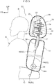
- the vehicle seat 10 of the present embodiment is structured to include a seat cushion 12, a seatback 14 and a headrest 16.
- the seat cushion 12 is structured so as to support the femoral regions and the buttocks of a vehicle occupant from the lower side.
- the seatback 14 is rotatably connected to the seat rear side of the seat cushion 12.
- the seatback 14 extends toward the seat upper side from the seat cushion 12, and is structured such that the back portion of the vehicle occupant can be supported by the seatback 14. Further, the headrest 16, which can support the head portion of the vehicle occupant from the seat rear side, is mounted to the end portion at the seat upper side (the upper end portion) of the seatback 14.
- headrest stays 17 that extend in the seat vertical direction are provided at the interior of the headrest 16.
- the lower portions of these headrest stays 17 project-out toward the seat lower side from the headrest 16 and are inserted in the seatback 14.
- Stay mounting holes 14A are formed in the upper end portion of the seatback 14.
- Stay guiding members 19 are mounted in these stay mounting holes 14A.
- the stay guiding members 19 are substantially cylindrical tube shaped members whose axial directions are the seat vertical direction, and the upper end portions of the stay guiding members 19 are at the same height as the upper end portion of the seatback 14.
- the headrest stays 17 are inserted in the stay guiding members 19.
- a headrest pad 18 is provided at the seat front side of the interior of the headrest 16.
- the headrest pad 18 is covered by a skin 21.
- a supporting plate 20 is provided at the seat rear side of the headrest pad 18.
- the supporting plate 20 is disposed such that the plate thickness direction thereof is the seat longitudinal direction, and extends in the seat transverse direction and the seat vertical direction. Further, the headrest pad 18 is supported from the seat rear side by the supporting plate 20.
- Plural rods 22 are mounted to the supporting plate 20.
- the rods 22 extend toward the seat rear side from the rear surface of the supporting plate 20.
- four of the rods 22 that are parallel to one another are mounted. (In Fig. 1 , the two rods 22 that are at the seat left side are illustrated.)
- Each of the rods 22 is slidably inserted in a rod guide 24 that is substantially shaped as a cylindrical tube and is provided at a base plate 26.
- the base plate 26 is provided between the left and right headrest stays 17 with the plate thickness direction thereof being the seat longitudinal direction.
- Four through-holes 26A are formed in the base plate 26.
- the rod guides 24 are fit-together with these through-holes 26A, and the respective rod guides 24 are provided at positions corresponding to the rods 22. Therefore, the base plate 26 is structured so as to be moved in the seat longitudinal direction due to the rods 22 sliding along the rod guides 24.
- the supporting plate 20 and the base plate 26 are connected by a compression coil spring 28 that serves as an urging member.
- the compression coil spring 28 is disposed between the supporting plate 20 and the base plate 26, and one end portion of the compression coil spring 28 is fixed to the rear surface of the base plate 20.
- another end portion of the compression coil spring 28 is fixed to the front surface of the base plate 26. Therefore, the supporting plate 20 is urged toward the seat front side by the urging force from the compression coil spring 28, and the headrest pad 18 is set in a compressed state.
- the vehicle seat 10 has a moving mechanism 30 that moves the supporting plate 20.
- a hardness changing section is structured to include this moving mechanism 30, the supporting plate 20 and the compression coil spring 28. The hardness of the headrest 16 can be changed by this hardness changing section.
- the moving mechanism 30 is structured to include a wire 34 and a take-up device 32.
- the wire 34 extends in the seat vertical direction along the headrest stays 17.
- the upper end portion of the wire 34 is trained around a guide roller 25 and extends toward the seat front side, and is fixed to the rear surface of the supporting plate 20.
- the lower end portion of the wire 34 is connected to the take-up device 32 that is provided at the interior of the seatback 14.
- the take-up device 32 has a spool 32A on which the lower end portion of the wire 34 is wound. Further, the take-up device 32 has an unillustrated motor, and is structured such that the spool 32A rotates due to this motor being driven.
- the take-up device 32 is electrically connected to an unillustrated control section such as an ECU (Electronic Control Unit) or the like. Due to the motor being driven on the basis of signals from the ECU, the wire 34 is taken-up, or the wire 34 is pulled-out.
- ECU Electronic Control Unit
- a recliner 36 for moving the seatback 14 with respect to the seat cushion 12 is provided at the lower end portion of the seatback 14.
- a motor 38 is mounted to the recliner 36. Due to this motor 38 being driven, the seatback 14 is rotated in the seat longitudinal direction around a rotation shaft 36A with respect to the seat cushion 12.
- a sensor 40 such as a rotary encoder or the like is provided at the motor 38.
- the angle of inclination of the seatback 14 with respect to the seat cushion 12 can be detected by this sensor 40. Further, the sensor 40 is electrically connected to the ECU.
- the present embodiment is structured such that, in a case in which the angle of inclination of the seatback 14 that is detected by the sensor 40 changes, the supporting plate 20 is moved by the moving mechanism 30. Movement of the supporting plate 20 by the moving mechanism 30 is described in detail hereinafter.
- the angle of inclination of the seatback 14 is relatively small.
- the moving mechanism 30 does not operate, and therefore, the wire 34 is in a state of being pulled-out from the take-up device 32.
- the supporting plate 20 is urged toward the seat front side by the compression coil spring 28, and therefore, the headrest pad 18 is maintained in a compressed state.
- the seat front side portion of the headrest 16 (the portion that supports a head portion H of the driver D) is hard.
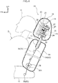
- the spool 32A Due to the take-up device 32 being operated, the spool 32A is rotated in the direction of taking-up the wire 34. Due thereto, the wire 34 is taken-up onto the spool 32A, and the tension applied tot the wire 34 increases. Further, when the tension that is applied to the wire 34 becomes greater than the urging force of the compression coil spring 28, the supporting plate 20 is moved toward the seat rear side against the urging force of the compression coil spring 28. Due thereto, the compressed state of the headrest pad 18 is cancelled, and the headrest 16 becomes soft.
- the headrest pad 18 is compressed by the hardness changing section. Further, in a case in which the angle of inclination of the seatback 14 becomes large, the compressed state of the headrest pad 18 is cancelled by the hardness changing section. In this way, the hardness of the seat front side of the headrest 16 is changed.
- the headrest pad 18 is compressed. Due thereto, the headrest can be made to be hard during driving by the driver D.
- the compressed state of the headrest pad 18 is cancelled. Due thereto, the headrest 16 can be made to be soft when the seatback 14 is in the reclined state. In this way, the hardness of the headrest 16 can be changed between times of driving and times when the seatback 14 is in a reclined state. Further, if the headrest 16 is made to be soft when the seatback 14 is in a reclined state, the comfort of the driver D can be improved.
- the state in which the supporting plate 20 is urged toward the seat front side by the compression coil spring is supported. Due thereto, when the seatback 14 is in an upright state, cancelling of the compressed state of the headrest pad 18 can be suppressed. Namely, the safety of the driver D can be improved.
- the present embodiment is structured such that the moving mechanism 30 is operated when the angle of inclination of the seatback 14 becomes greater than a predetermined angle. Due thereto, the headrest 16 becoming soft while the seatback 14 is in a range of reclining angles that are generally used during driving can be suppressed. Namely, the headrest 16 can be made to be soft only in cases in which the driver D is in a relaxed posture.
- a vehicle seat 50 relating to a second exemplary embodiment is described next with reference to Fig. 3 and Fig. 4 .
- Note that structures that are similar to those of the first exemplary embodiment are denoted by the same reference numerals, and description thereof is omitted as appropriate.
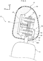
- a moving mechanism 52 that is provided at the vehicle seat 50 of the present embodiment is structured to include a wire 54, a guide roller 56 that serves as a guiding member, and an anchor 58.
- the wire 54 extends in the seat vertical direction.
- the upper end portion (one end portion) of the wire 54 is trained around the guide roller 25, and extends toward the seat front side, and is fixed to the rear surface of the supporting plate 20. Further, the wire 54 extends from the guide roller 25 through the interiors of the seatback 14 and the seat cushion 12 toward the seat lower side, and the lower end portion (another end portion) of the wire 54 is fixed to the anchor 58 that is at the interior of the seat cushion 12.
- the guide roller 56 which supports the wire 54 from the seat front side and guides the wire 54, is provided at the interior of the seatback 14. This guide roller 56 is fixed to an unillustrated seatback frame.
- the wire 54 is supported from the seat rear side by the rotating shaft 36A of the recliner 36. Note that the recliner 36 of the vehicle seat 40 of the present embodiment is manually operated, and the motor 38 is not mounted thereto.
- the present embodiment is structured such that, in a case in which the angle of inclination of the seatback 14 becomes greater than a predetermined angle, the compressed state of the headrest 16 is cancelled.
- the headrest 16 can be made to be soft only in cases in which the driver D is in a comfortable posture. Namely, in a case in which the seatback 14 is tilted only slightly toward the seat rear side, the tension spring stretches, but the supporting plate 20 itself is not pulled, and therefore, the headrest pad 18 can be maintained in a compressed state.
- the spring constant of the tension spring is adjusted and it is made such that the tension spring can stretch in cases in which the angle of inclination of the seatback 14 is greater than a predetermined angle, in cases in which the driver D is in a comfortable posture, the supporting plate 20 moves toward the seat rear side, and the compressed state of the headrest pad 18 can be cancelled.
- the tension that is mechanically applied to the wire 54 can be made to be large, and therefore, there is no need for a part such as a motor or the like for taking-up the wire. Namely, a complex structure is not needed, and the hardness of the headrest 16 can be changed by a simple structure. Further, by eliminating electrical parts, lightening of the weight can be devised.
- the hardness of the headrest 16 can be changed even in a state in which electricity is not being supplied. Therefore, for example, even in a case in which the driver D sets the seatback 14 in a reclined state in a state in which the ignition is off, the headrest 16 can be made to be soft. Other operations are similar to those of the first exemplary embodiment.
- a vehicle seat 60 relating to a third exemplary embodiment is described next with reference to Fig. 5 and Fig. 6 .
- Note that structures that are similar to those of the first exemplary embodiment are denoted by the same reference numerals, and description thereof is omitted as appropriate.
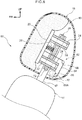
- a moving mechanism 62 of the vehicle seat 60 of the present embodiment is structured to include a wire 64, a take-up device 66 and a sensor 72. All of these parts are provided at the interior of the headrest 16.
- the wire 64 is routed at the interior of the headrest 16, and one end portion of the wire 64 is fixed to the rear surface of the supporting plate 20. Another end side of the wire 64 extends from the supporting plate 20 toward the seat rear side, and is trained around an upper side guide roller 68, and extends toward the seat lower side. Moreover, the wire 64 is trained around a lower side guide roller 70, and the another end portion of the wire 64 is connected to the take-up device 66.
- the take-up device 66 has a spool 66A around which the lower end portion of the wire 64 is wound.
- the take-up device 66 has an unillustrated motor, and is structured such that the spool 66A rotates due to the motor being driven. Further, the take-up device 66 is electrically connected to a control section such as an unillustrated ECU (Electronic Control Unit) or the like. Due to the motor being driven on the basis of signals from the ECU, the wire 64 is taken-up, or the wire 64 is pulled-out.
- ECU Electronic Control Unit
- the sensor 72 is mounted to the lower end portion of the base plate 26.
- a sensor which can detect the angle of inclination of the headrest 16 such as a gyro sensor or an angle sensor or the like, is used as the sensor 72. Due to the angle of the headrest 16 being detected by the sensor 72, the angle of inclination of the seatback 14 with respect to the seat cushion can be detected indirectly. Further, the sensor 72 is electrically connected to the ECU.
- the ECU judges, from the angle of the headrest 16 that is detected by the sensor 72, that the angle of inclination of the seatback 14 has become greater than a predetermined angle, and operates the take-up device 66.
- the spool 66A is rotated in the direction of taking-up the wire 64, and the tension that is applied to the wire 64 increases.
- the tension that is applied to the wire 64 becomes greater than the urging force of the compression coil spring 28, the supporting plate 20 is moved toward the seat rear side against the urging force of the compression coil spring 28. Due thereto, the compressed state of the headrest pad 18 is cancelled, and the headrest 16 becomes soft.
- the ECU judges, from the angle of the headrest 16 that is detected by the sensor 72, that the angle of inclination of the seatback 14 has become smaller than the predetermined angle, and the take-up device 66 is operated. Due to the take-up device 66 being operated, the spool 66A is rotated in the direction of pulling-out the wire 64. Due thereto, the tension that is applied to the wire 64 decreases, and the urging force of the compression coil spring 28 becomes larger than this tension, and the supporting plate 20 moves toward the seat front side. As a result, the headrest pad 18 is compressed.
- the moving mechanism 62 is provided at the interior of the headrest 16, the moving mechanism 62 can be added to the vehicle seat 60 that has already been manufactured, merely by replacing the headrest. Namely, the moving mechanism 62 can easily be added-on later, as compared with a structure that has the moving mechanism 62 such as the take-up device 66 and the like at the interior of the seatback 14. Other operations are similar to those of the first exemplary embodiment.
- first through third exemplary embodiments have been described above, the present disclosure can, of course, be implemented in various forms within a scope that does not depart from the gist thereof.
- the first exemplary embodiment and the third exemplary embodiment are structured such that the supporting plate 20 is moved and the headrest 16 is made to be a given softness in a case in which the angle of inclination of the seatback 14 becomes greater than a predetermined angle.
- the present disclosure is not limited to this. Namely, the headrest 16 can be made to be softer gradually by changing the amount of movement of the supporting plate 20 in accordance with the angle of inclination.
- the compression coil spring 28 is used as the urging member.
- the present disclosure is not limited to this, and another urging member may be used.
- a plate spring or a cylinder or the like may be used as the urging member.
- an electric cylinder may be disposed at the interior of the headrest 16, and the rod of this electric cylinder may be fixed to the rear surface of the supporting plate 20.
- the supporting plate 20 can be moved toward the seat front side, and the headrest pad 18 can be compressed.
- the supporting plate 20 can be moved toward the seat rear side by the tension of the wire, and the compressed state of the headrest pad 18 can be cancelled.
Landscapes
- Engineering & Computer Science (AREA)
- Aviation & Aerospace Engineering (AREA)
- Transportation (AREA)
- Mechanical Engineering (AREA)
- Seats For Vehicles (AREA)
Claims (5)
- Fahrzeugsitz, umfassend:ein Sitzkissen (12),eine Rückenlehne (14), die mit einer Sitzrückseite des Sitzkissens (12) rotierbar verbunden ist,eine Kopfstütze (16), die an einem Sitzoberseiten-Endabschnitt der Rückenlehne (14) vorgesehen ist und die dazu ausgestaltet ist, einen Kopfabschnitt (H) eines Fahrzeuginsassen (D) zu tragen, undeine Härteänderungssektion (20), die dazu ausgestaltet ist, eine Härte einer Sitzvorderseite der Kopfstütze (16) durch Komprimieren eines Polsters (18) an einem Inneren der Kopfstütze (16) in einem Fall, in dem ein Neigungswinkel der Rückenlehne (14) in Bezug auf das Sitzkissen (12) kleiner als ein vorbestimmter Winkel ist, und Aufheben eines komprimierten Zustands des Polsters (18) in einem Fall zu ändern, in dem der Neigungswinkel größer als der vorbestimmte Winkel ist.
- Fahrzeugsitz nach Anspruch 1, wobei die Härteänderungssektion (20) so strukturiert ist, dass sie beinhaltet:eine Trägerplatte (20), die an einer Sitzrückseite des Polsters (18) angeordnet ist und dazu ausgestaltet ist, sich in einer Sitzlängsrichtung zu bewegen,ein Drängelement (28), das die Trägerplatte (20) in Richtung einer Sitzvorderseite drängt, undeinen Bewegungsmechanismus (30), der dazu ausgestaltet ist, die Trägerplatte (20) zu betreiben und in Richtung einer Sitzrückseite in einem Fall zu bewegen, in dem der Neigungswinkel größer als der vorbestimmte Winkel ist.
- Fahrzeugsitz nach Anspruch 2, wobei:der Bewegungsmechanismus (30) so strukturiert ist, dass er eine Aufnahmevorrichtung (32), die an einem Inneren der Rückenlehne (14) vorgesehen ist, und einen Draht (34) beinhaltet, der einen Endabschnitt aufweist, der an der Trägerplatte (20) angebracht ist, und einen weiteren Endabschnitt aufweist, der an der Aufnahmevorrichtung (32) gewickelt ist, undder Draht (34) von der Aufnahmevorrichtung (32) in einem Fall aufzunehmen ist, in dem der Neigungswinkel groß ist, und der Draht (34) aus der Aufnahmevorrichtung (32) in einem Fall herauszuziehen ist, in dem der Neigungswinkel klein ist.
- Fahrzeugsitz nach Anspruch 2, wobei:der Bewegungsmechanismus (52) so strukturiert ist, dass er einen Draht (54), der einen Endabschnitt aufweist, der an der Trägerplatte (20) angebracht ist, und einen weiteren Endabschnitt aufweist, der an einem Inneren des Sitzkissens (12) angebracht ist, und ein Führungselement (56) beinhaltet, das an einem Inneren der Rückenlehne (14) vorgesehen ist und das den Draht (54) führt, undin einem Fall, in dem der Neigungswinkel groß ist, aufgrund dessen, dass das sich in Richtung der Sitzrückseite bewegende Führungselement (56) mit der Rotation der Rückenlehne (14) einhergeht, eine Spannung, die auf den Draht (54) ausgeübt wird, erhöht wird und in einem Fall, in dem der Neigungswinkel klein ist, aufgrund dessen, dass das sich in Richtung der Sitzvorderseite bewegende Führungselement (56) mit der Rotation der Rückenlehne (14) einhergeht, die Spannung, die auf den Draht (54) ausgeübt wird, erniedrigt wird.
- Fahrzeugsitz nach Anspruch 2, wobei:der Bewegungsmechanismus (62) so strukturiert ist, dass er eine Aufnahmevorrichtung (66), die an einem Inneren der Kopfstütze (16) vorgesehen ist, und einen Draht (64) beinhaltet, der einen Endabschnitt aufweist, der an der Trägerplatte (20) angebracht ist, und einen weiteren Endabschnitt aufweist, der an der Aufnahmevorrichtung (32) gewickelt ist, undder Draht (64) von der Aufnahmevorrichtung (66) in einem Fall aufzunehmen ist, in dem der Neigungswinkel groß ist, und der Draht (64) aus der Aufnahmevorrichtung (66) in einem Fall herauszuziehen ist, in dem der Neigungswinkel klein ist.
Applications Claiming Priority (1)
| Application Number | Priority Date | Filing Date | Title |
|---|---|---|---|
| JP2018148875A JP7003872B2 (ja) | 2018-08-07 | 2018-08-07 | 車両用シート |
Publications (2)
| Publication Number | Publication Date |
|---|---|
| EP3613632A1 EP3613632A1 (de) | 2020-02-26 |
| EP3613632B1 true EP3613632B1 (de) | 2021-04-21 |
Family
ID=67184881
Family Applications (1)
| Application Number | Title | Priority Date | Filing Date |
|---|---|---|---|
| EP19184686.4A Active EP3613632B1 (de) | 2018-08-07 | 2019-07-05 | Fahrzeugsitz |
Country Status (4)
| Country | Link |
|---|---|
| US (1) | US10836290B2 (de) |
| EP (1) | EP3613632B1 (de) |
| JP (1) | JP7003872B2 (de) |
| CN (1) | CN110816375B (de) |
Families Citing this family (6)
| Publication number | Priority date | Publication date | Assignee | Title |
|---|---|---|---|---|
| US11584277B1 (en) * | 2018-03-23 | 2023-02-21 | Life Aligned Safety Products Llc | Reduced-impact-and-recoil headrest |
| JP7003872B2 (ja) * | 2018-08-07 | 2022-01-21 | トヨタ自動車株式会社 | 車両用シート |
| CN111823987A (zh) * | 2020-07-27 | 2020-10-27 | 盐城工学院 | 一种汽车座椅靠枕调节装置 |
| CN113561856B (zh) * | 2021-06-30 | 2022-09-27 | 东风汽车集团股份有限公司 | 一种基于汽车座椅总成的舒适安全联动系统 |
| DE102021118485A1 (de) * | 2021-07-16 | 2023-01-19 | Bayerische Motoren Werke Aktiengesellschaft | Fahrzeugsitz mit einem Schwingungstilger |
| CN116923212A (zh) * | 2022-04-08 | 2023-10-24 | 丰田纺织株式会社 | 交通工具用座椅 |
Family Cites Families (30)
| Publication number | Priority date | Publication date | Assignee | Title |
|---|---|---|---|---|
| JP2835775B2 (ja) * | 1990-08-30 | 1998-12-14 | 株式会社タチエス | ヘッドレスト装置 |
| US5181763A (en) * | 1990-09-20 | 1993-01-26 | Ronald P. Dellanno | Apparatus for preventing whiplash |
| US5769489A (en) * | 1997-05-09 | 1998-06-23 | Dellanno; Ronald P. | Energy absorbing support for vehicular passengers |
| DE19904738A1 (de) * | 1999-02-05 | 2000-08-10 | Volkswagen Ag | Fahrzeugsitz mit einer crashaktiven Kopfstütze |
| DE19944719C1 (de) * | 1999-09-17 | 2001-01-11 | Lear Corp Gmbh & Co Kg | Fahrzeugsitz |
| DE10209187C1 (de) * | 2002-03-04 | 2003-08-28 | Daimler Chrysler Ag | Fahrzeugsitz mit Kopfstütze mit Nacken- und Seitenabstützung |
| JP4661179B2 (ja) * | 2004-11-18 | 2011-03-30 | トヨタ紡織株式会社 | 車両用シートのヘッドレスト装置 |
| JP4517882B2 (ja) * | 2005-02-21 | 2010-08-04 | マツダ株式会社 | 車両用シート |
| JP2006315623A (ja) | 2005-05-16 | 2006-11-24 | Nissan Motor Co Ltd | 車両用シート |
| DE112007000947B4 (de) * | 2006-04-17 | 2016-07-28 | GM Global Technology Operations LLC (n. d. Ges. d. Staates Delaware) | Durch aktives Material betätigte Kopfstütze, Verfahren zum selektiven Umkonfigurieren einer Form oder einer Moduleigenschaft einer Kopfstütze sowie Kopfstützenanordnung |
| DE102007036466A1 (de) * | 2006-12-18 | 2008-06-19 | Brose Fahrzeugteile Gmbh & Co. Kommanditgesellschaft, Coburg | Crash-optimierter Kraftfahrzeugsitz |
| JP4358255B2 (ja) * | 2007-04-20 | 2009-11-04 | トヨタ紡織株式会社 | 車両用シート |
| JP2009234286A (ja) * | 2008-03-25 | 2009-10-15 | Aisin Seiki Co Ltd | 車両用ヘッドレスト装置 |
| DE102009037778A1 (de) * | 2009-08-18 | 2011-04-28 | Grammer Ag | Kopfstütze |
| EP3354514B1 (de) * | 2010-12-24 | 2019-11-27 | TS Tech Co., Ltd. | Fahrzeugsitz |
| WO2012111097A1 (ja) * | 2011-02-15 | 2012-08-23 | トヨタ自動車株式会社 | 車両用ヘッドレスト装置 |
| JP5250073B2 (ja) * | 2011-03-30 | 2013-07-31 | 日本発條株式会社 | 車両用シート |
| CN103974857B (zh) * | 2011-11-29 | 2017-10-27 | 提爱思科技股份有限公司 | 安装部件及安全气囊模块装备座椅 |
| JP2013116660A (ja) * | 2011-12-02 | 2013-06-13 | Toyota Boshoku Corp | ヘッドレスト |
| JP5925575B2 (ja) * | 2012-04-23 | 2016-05-25 | 日本発條株式会社 | ヘッドレスト装置 |
| JP2014008335A (ja) * | 2012-07-02 | 2014-01-20 | Toyota Motor Corp | ヘッドレスト支持構造 |
| JP5696705B2 (ja) * | 2012-09-25 | 2015-04-08 | トヨタ自動車株式会社 | ヘッドレスト及びこれを備えた車両用シート |
| JP5850169B2 (ja) * | 2012-09-25 | 2016-02-03 | トヨタ自動車株式会社 | ヘッドレスト及びこれを備えた車両用シート、並びにヘッドレストの製造方法 |
| JP6102771B2 (ja) * | 2014-01-29 | 2017-03-29 | トヨタ紡織株式会社 | 可動式ヘッドレスト |
| DE102014224835B4 (de) * | 2014-12-04 | 2022-07-21 | Bayerische Motoren Werke Aktiengesellschaft | Kopfstütze |
| US10052987B2 (en) * | 2016-08-25 | 2018-08-21 | Ts Tech Co., Ltd. | Vehicle seat |
| US10065542B2 (en) * | 2017-01-31 | 2018-09-04 | Toyota Motor Engineering & Manufacturing North America, Inc. | Vehicle occupant cooling system |
| US10471870B2 (en) * | 2017-10-06 | 2019-11-12 | GM Global Technology Operations LLC | Multi-zone seat suspension |
| EP3531715B1 (de) * | 2018-02-27 | 2022-02-09 | Flexound Systems OY | Für verbesserte tonwahrnehmung über vibrationen angeordneter sitz |
| JP7003872B2 (ja) * | 2018-08-07 | 2022-01-21 | トヨタ自動車株式会社 | 車両用シート |
-
2018
- 2018-08-07 JP JP2018148875A patent/JP7003872B2/ja not_active Expired - Fee Related
-
2019
- 2019-06-28 CN CN201910574790.7A patent/CN110816375B/zh not_active Expired - Fee Related
- 2019-07-05 EP EP19184686.4A patent/EP3613632B1/de active Active
- 2019-07-05 US US16/503,867 patent/US10836290B2/en active Active
Non-Patent Citations (1)
| Title |
|---|
| None * |
Also Published As
| Publication number | Publication date |
|---|---|
| US10836290B2 (en) | 2020-11-17 |
| US20200047653A1 (en) | 2020-02-13 |
| EP3613632A1 (de) | 2020-02-26 |
| JP2020023262A (ja) | 2020-02-13 |
| CN110816375A (zh) | 2020-02-21 |
| JP7003872B2 (ja) | 2022-01-21 |
| CN110816375B (zh) | 2022-07-19 |
Similar Documents
| Publication | Publication Date | Title |
|---|---|---|
| EP3613632B1 (de) | Fahrzeugsitz | |
| US7614693B2 (en) | Seating area adjuster | |
| CN110861550B (zh) | 车辆用座椅 | |
| US7874616B2 (en) | Horizontal lumbar suspension for vehicle seats | |
| US8585139B2 (en) | Vehicle seat | |
| US7992933B2 (en) | Integrated vehicle seat with active head restraint system | |
| US11338716B2 (en) | Vehicle footrest | |
| US20140203614A1 (en) | Integrated thin flex composite headrest assembly | |
| US20150375647A1 (en) | Vehicle seat, in particular for a motor vehicle | |
| EP3323674A1 (de) | Fahrzeugsitz | |
| JP2020050049A (ja) | 車両用乗員拘束装置 | |
| WO2015092505A1 (en) | Side support adjuster | |
| JP2005212596A (ja) | 車両用シート | |
| KR102153216B1 (ko) | 자동차용 멀티 포지션 시트 | |
| CA2779920A1 (en) | In-line recliner return mechanism | |
| US11731539B2 (en) | Vehicle occupant restraint device | |
| JP7614494B2 (ja) | 乗物用シートのクッション長さ調整装置 | |
| JP4241800B2 (ja) | 車両用シート | |
| JP2007106355A (ja) | シートベルト装置 | |
| JP2009234286A (ja) | 車両用ヘッドレスト装置 | |
| JP4834730B2 (ja) | 伸縮式足掛け付きアームチェア | |
| US9119472B2 (en) | Movable seat insert | |
| JP6064922B2 (ja) | 車両用シート装置 | |
| JP7096472B2 (ja) | 乗物用シート | |
| JP2009195419A (ja) | 車両用シート |
Legal Events
| Date | Code | Title | Description |
|---|---|---|---|
| PUAI | Public reference made under article 153(3) epc to a published international application that has entered the european phase |
Free format text: ORIGINAL CODE: 0009012 |
|
| STAA | Information on the status of an ep patent application or granted ep patent |
Free format text: STATUS: REQUEST FOR EXAMINATION WAS MADE |
|
| 17P | Request for examination filed |
Effective date: 20190705 |
|
| AK | Designated contracting states |
Kind code of ref document: A1 Designated state(s): AL AT BE BG CH CY CZ DE DK EE ES FI FR GB GR HR HU IE IS IT LI LT LU LV MC MK MT NL NO PL PT RO RS SE SI SK SM TR |
|
| AX | Request for extension of the european patent |
Extension state: BA ME |
|
| GRAP | Despatch of communication of intention to grant a patent |
Free format text: ORIGINAL CODE: EPIDOSNIGR1 |
|
| STAA | Information on the status of an ep patent application or granted ep patent |
Free format text: STATUS: GRANT OF PATENT IS INTENDED |
|
| INTG | Intention to grant announced |
Effective date: 20201130 |
|
| GRAS | Grant fee paid |
Free format text: ORIGINAL CODE: EPIDOSNIGR3 |
|
| GRAA | (expected) grant |
Free format text: ORIGINAL CODE: 0009210 |
|
| STAA | Information on the status of an ep patent application or granted ep patent |
Free format text: STATUS: THE PATENT HAS BEEN GRANTED |
|
| AK | Designated contracting states |
Kind code of ref document: B1 Designated state(s): AL AT BE BG CH CY CZ DE DK EE ES FI FR GB GR HR HU IE IS IT LI LT LU LV MC MK MT NL NO PL PT RO RS SE SI SK SM TR |
|
| REG | Reference to a national code |
Ref country code: GB Ref legal event code: FG4D |
|
| REG | Reference to a national code |
Ref country code: CH Ref legal event code: EP |
|
| REG | Reference to a national code |
Ref country code: DE Ref legal event code: R096 Ref document number: 602019004018 Country of ref document: DE Ref country code: IE Ref legal event code: FG4D |
|
| REG | Reference to a national code |
Ref country code: AT Ref legal event code: REF Ref document number: 1384302 Country of ref document: AT Kind code of ref document: T Effective date: 20210515 |
|
| REG | Reference to a national code |
Ref country code: LT Ref legal event code: MG9D |
|
| REG | Reference to a national code |
Ref country code: AT Ref legal event code: MK05 Ref document number: 1384302 Country of ref document: AT Kind code of ref document: T Effective date: 20210421 |
|
| REG | Reference to a national code |
Ref country code: NL Ref legal event code: MP Effective date: 20210421 |
|
| PG25 | Lapsed in a contracting state [announced via postgrant information from national office to epo] |
Ref country code: HR Free format text: LAPSE BECAUSE OF FAILURE TO SUBMIT A TRANSLATION OF THE DESCRIPTION OR TO PAY THE FEE WITHIN THE PRESCRIBED TIME-LIMIT Effective date: 20210421 Ref country code: LT Free format text: LAPSE BECAUSE OF FAILURE TO SUBMIT A TRANSLATION OF THE DESCRIPTION OR TO PAY THE FEE WITHIN THE PRESCRIBED TIME-LIMIT Effective date: 20210421 Ref country code: FI Free format text: LAPSE BECAUSE OF FAILURE TO SUBMIT A TRANSLATION OF THE DESCRIPTION OR TO PAY THE FEE WITHIN THE PRESCRIBED TIME-LIMIT Effective date: 20210421 Ref country code: AT Free format text: LAPSE BECAUSE OF FAILURE TO SUBMIT A TRANSLATION OF THE DESCRIPTION OR TO PAY THE FEE WITHIN THE PRESCRIBED TIME-LIMIT Effective date: 20210421 Ref country code: BG Free format text: LAPSE BECAUSE OF FAILURE TO SUBMIT A TRANSLATION OF THE DESCRIPTION OR TO PAY THE FEE WITHIN THE PRESCRIBED TIME-LIMIT Effective date: 20210721 Ref country code: NL Free format text: LAPSE BECAUSE OF FAILURE TO SUBMIT A TRANSLATION OF THE DESCRIPTION OR TO PAY THE FEE WITHIN THE PRESCRIBED TIME-LIMIT Effective date: 20210421 |
|
| PG25 | Lapsed in a contracting state [announced via postgrant information from national office to epo] |
Ref country code: IS Free format text: LAPSE BECAUSE OF FAILURE TO SUBMIT A TRANSLATION OF THE DESCRIPTION OR TO PAY THE FEE WITHIN THE PRESCRIBED TIME-LIMIT Effective date: 20210821 Ref country code: GR Free format text: LAPSE BECAUSE OF FAILURE TO SUBMIT A TRANSLATION OF THE DESCRIPTION OR TO PAY THE FEE WITHIN THE PRESCRIBED TIME-LIMIT Effective date: 20210722 Ref country code: PL Free format text: LAPSE BECAUSE OF FAILURE TO SUBMIT A TRANSLATION OF THE DESCRIPTION OR TO PAY THE FEE WITHIN THE PRESCRIBED TIME-LIMIT Effective date: 20210421 Ref country code: LV Free format text: LAPSE BECAUSE OF FAILURE TO SUBMIT A TRANSLATION OF THE DESCRIPTION OR TO PAY THE FEE WITHIN THE PRESCRIBED TIME-LIMIT Effective date: 20210421 Ref country code: NO Free format text: LAPSE BECAUSE OF FAILURE TO SUBMIT A TRANSLATION OF THE DESCRIPTION OR TO PAY THE FEE WITHIN THE PRESCRIBED TIME-LIMIT Effective date: 20210721 Ref country code: RS Free format text: LAPSE BECAUSE OF FAILURE TO SUBMIT A TRANSLATION OF THE DESCRIPTION OR TO PAY THE FEE WITHIN THE PRESCRIBED TIME-LIMIT Effective date: 20210421 Ref country code: SE Free format text: LAPSE BECAUSE OF FAILURE TO SUBMIT A TRANSLATION OF THE DESCRIPTION OR TO PAY THE FEE WITHIN THE PRESCRIBED TIME-LIMIT Effective date: 20210421 Ref country code: PT Free format text: LAPSE BECAUSE OF FAILURE TO SUBMIT A TRANSLATION OF THE DESCRIPTION OR TO PAY THE FEE WITHIN THE PRESCRIBED TIME-LIMIT Effective date: 20210823 |
|
| REG | Reference to a national code |
Ref country code: DE Ref legal event code: R097 Ref document number: 602019004018 Country of ref document: DE |
|
| PG25 | Lapsed in a contracting state [announced via postgrant information from national office to epo] |
Ref country code: ES Free format text: LAPSE BECAUSE OF FAILURE TO SUBMIT A TRANSLATION OF THE DESCRIPTION OR TO PAY THE FEE WITHIN THE PRESCRIBED TIME-LIMIT Effective date: 20210421 Ref country code: EE Free format text: LAPSE BECAUSE OF FAILURE TO SUBMIT A TRANSLATION OF THE DESCRIPTION OR TO PAY THE FEE WITHIN THE PRESCRIBED TIME-LIMIT Effective date: 20210421 Ref country code: SK Free format text: LAPSE BECAUSE OF FAILURE TO SUBMIT A TRANSLATION OF THE DESCRIPTION OR TO PAY THE FEE WITHIN THE PRESCRIBED TIME-LIMIT Effective date: 20210421 Ref country code: CZ Free format text: LAPSE BECAUSE OF FAILURE TO SUBMIT A TRANSLATION OF THE DESCRIPTION OR TO PAY THE FEE WITHIN THE PRESCRIBED TIME-LIMIT Effective date: 20210421 Ref country code: DK Free format text: LAPSE BECAUSE OF FAILURE TO SUBMIT A TRANSLATION OF THE DESCRIPTION OR TO PAY THE FEE WITHIN THE PRESCRIBED TIME-LIMIT Effective date: 20210421 Ref country code: SM Free format text: LAPSE BECAUSE OF FAILURE TO SUBMIT A TRANSLATION OF THE DESCRIPTION OR TO PAY THE FEE WITHIN THE PRESCRIBED TIME-LIMIT Effective date: 20210421 Ref country code: RO Free format text: LAPSE BECAUSE OF FAILURE TO SUBMIT A TRANSLATION OF THE DESCRIPTION OR TO PAY THE FEE WITHIN THE PRESCRIBED TIME-LIMIT Effective date: 20210421 |
|
| PLBE | No opposition filed within time limit |
Free format text: ORIGINAL CODE: 0009261 |
|
| STAA | Information on the status of an ep patent application or granted ep patent |
Free format text: STATUS: NO OPPOSITION FILED WITHIN TIME LIMIT |
|
| 26N | No opposition filed |
Effective date: 20220124 |
|
| PG25 | Lapsed in a contracting state [announced via postgrant information from national office to epo] |
Ref country code: MC Free format text: LAPSE BECAUSE OF FAILURE TO SUBMIT A TRANSLATION OF THE DESCRIPTION OR TO PAY THE FEE WITHIN THE PRESCRIBED TIME-LIMIT Effective date: 20210421 |
|
| REG | Reference to a national code |
Ref country code: BE Ref legal event code: MM Effective date: 20210731 |
|
| PG25 | Lapsed in a contracting state [announced via postgrant information from national office to epo] |
Ref country code: IS Free format text: LAPSE BECAUSE OF FAILURE TO SUBMIT A TRANSLATION OF THE DESCRIPTION OR TO PAY THE FEE WITHIN THE PRESCRIBED TIME-LIMIT Effective date: 20210821 Ref country code: LU Free format text: LAPSE BECAUSE OF NON-PAYMENT OF DUE FEES Effective date: 20210705 Ref country code: AL Free format text: LAPSE BECAUSE OF FAILURE TO SUBMIT A TRANSLATION OF THE DESCRIPTION OR TO PAY THE FEE WITHIN THE PRESCRIBED TIME-LIMIT Effective date: 20210421 |
|
| PG25 | Lapsed in a contracting state [announced via postgrant information from national office to epo] |
Ref country code: IT Free format text: LAPSE BECAUSE OF FAILURE TO SUBMIT A TRANSLATION OF THE DESCRIPTION OR TO PAY THE FEE WITHIN THE PRESCRIBED TIME-LIMIT Effective date: 20210421 Ref country code: IE Free format text: LAPSE BECAUSE OF NON-PAYMENT OF DUE FEES Effective date: 20210705 Ref country code: BE Free format text: LAPSE BECAUSE OF NON-PAYMENT OF DUE FEES Effective date: 20210731 |
|
| PGFP | Annual fee paid to national office [announced via postgrant information from national office to epo] |
Ref country code: FR Payment date: 20220510 Year of fee payment: 4 |
|
| PGFP | Annual fee paid to national office [announced via postgrant information from national office to epo] |
Ref country code: DE Payment date: 20220511 Year of fee payment: 4 |
|
| REG | Reference to a national code |
Ref country code: CH Ref legal event code: PL |
|
| PG25 | Lapsed in a contracting state [announced via postgrant information from national office to epo] |
Ref country code: LI Free format text: LAPSE BECAUSE OF NON-PAYMENT OF DUE FEES Effective date: 20220731 Ref country code: CH Free format text: LAPSE BECAUSE OF NON-PAYMENT OF DUE FEES Effective date: 20220731 |
|
| P01 | Opt-out of the competence of the unified patent court (upc) registered |
Effective date: 20230427 |
|
| PG25 | Lapsed in a contracting state [announced via postgrant information from national office to epo] |
Ref country code: CY Free format text: LAPSE BECAUSE OF FAILURE TO SUBMIT A TRANSLATION OF THE DESCRIPTION OR TO PAY THE FEE WITHIN THE PRESCRIBED TIME-LIMIT Effective date: 20210421 |
|
| PG25 | Lapsed in a contracting state [announced via postgrant information from national office to epo] |
Ref country code: HU Free format text: LAPSE BECAUSE OF FAILURE TO SUBMIT A TRANSLATION OF THE DESCRIPTION OR TO PAY THE FEE WITHIN THE PRESCRIBED TIME-LIMIT; INVALID AB INITIO Effective date: 20190705 |
|
| REG | Reference to a national code |
Ref country code: DE Ref legal event code: R119 Ref document number: 602019004018 Country of ref document: DE |
|
| GBPC | Gb: european patent ceased through non-payment of renewal fee |
Effective date: 20230705 |
|
| PG25 | Lapsed in a contracting state [announced via postgrant information from national office to epo] |
Ref country code: MK Free format text: LAPSE BECAUSE OF FAILURE TO SUBMIT A TRANSLATION OF THE DESCRIPTION OR TO PAY THE FEE WITHIN THE PRESCRIBED TIME-LIMIT Effective date: 20210421 Ref country code: DE Free format text: LAPSE BECAUSE OF NON-PAYMENT OF DUE FEES Effective date: 20240201 Ref country code: GB Free format text: LAPSE BECAUSE OF NON-PAYMENT OF DUE FEES Effective date: 20230705 |
|
| PG25 | Lapsed in a contracting state [announced via postgrant information from national office to epo] |
Ref country code: FR Free format text: LAPSE BECAUSE OF NON-PAYMENT OF DUE FEES Effective date: 20230731 |
|
| PG25 | Lapsed in a contracting state [announced via postgrant information from national office to epo] |
Ref country code: TR Free format text: LAPSE BECAUSE OF FAILURE TO SUBMIT A TRANSLATION OF THE DESCRIPTION OR TO PAY THE FEE WITHIN THE PRESCRIBED TIME-LIMIT Effective date: 20210421 |
|
| PG25 | Lapsed in a contracting state [announced via postgrant information from national office to epo] |
Ref country code: MT Free format text: LAPSE BECAUSE OF FAILURE TO SUBMIT A TRANSLATION OF THE DESCRIPTION OR TO PAY THE FEE WITHIN THE PRESCRIBED TIME-LIMIT Effective date: 20210421 |