EP3608296B1 - Herstellungsvorrichtung und herstellungsverfahren für poröse glasfaservorform - Google Patents
Herstellungsvorrichtung und herstellungsverfahren für poröse glasfaservorform Download PDFInfo
- Publication number
- EP3608296B1 EP3608296B1 EP18774435.4A EP18774435A EP3608296B1 EP 3608296 B1 EP3608296 B1 EP 3608296B1 EP 18774435 A EP18774435 A EP 18774435A EP 3608296 B1 EP3608296 B1 EP 3608296B1
- Authority
- EP
- European Patent Office
- Prior art keywords
- auxiliary burner
- porous preform
- burner
- starting material
- emission side
- Prior art date
- Legal status (The legal status is an assumption and is not a legal conclusion. Google has not performed a legal analysis and makes no representation as to the accuracy of the status listed.)
- Active
Links
Images



Classifications
-
- C—CHEMISTRY; METALLURGY
- C03—GLASS; MINERAL OR SLAG WOOL
- C03B—MANUFACTURE, SHAPING, OR SUPPLEMENTARY PROCESSES
- C03B37/00—Manufacture or treatment of flakes, fibres, or filaments from softened glass, minerals, or slags
- C03B37/01—Manufacture of glass fibres or filaments
- C03B37/012—Manufacture of preforms for drawing fibres or filaments
- C03B37/014—Manufacture of preforms for drawing fibres or filaments made entirely or partially by chemical means, e.g. vapour phase deposition of bulk porous glass either by outside vapour deposition [OVD], or by outside vapour phase oxidation [OVPO] or by vapour axial deposition [VAD]
- C03B37/01406—Deposition reactors therefor
-
- C—CHEMISTRY; METALLURGY
- C03—GLASS; MINERAL OR SLAG WOOL
- C03B—MANUFACTURE, SHAPING, OR SUPPLEMENTARY PROCESSES
- C03B37/00—Manufacture or treatment of flakes, fibres, or filaments from softened glass, minerals, or slags
- C03B37/01—Manufacture of glass fibres or filaments
- C03B37/012—Manufacture of preforms for drawing fibres or filaments
- C03B37/014—Manufacture of preforms for drawing fibres or filaments made entirely or partially by chemical means, e.g. vapour phase deposition of bulk porous glass either by outside vapour deposition [OVD], or by outside vapour phase oxidation [OVPO] or by vapour axial deposition [VAD]
- C03B37/01413—Reactant delivery systems
- C03B37/0142—Reactant deposition burners
-
- C—CHEMISTRY; METALLURGY
- C03—GLASS; MINERAL OR SLAG WOOL
- C03B—MANUFACTURE, SHAPING, OR SUPPLEMENTARY PROCESSES
- C03B37/00—Manufacture or treatment of flakes, fibres, or filaments from softened glass, minerals, or slags
- C03B37/01—Manufacture of glass fibres or filaments
- C03B37/012—Manufacture of preforms for drawing fibres or filaments
- C03B37/014—Manufacture of preforms for drawing fibres or filaments made entirely or partially by chemical means, e.g. vapour phase deposition of bulk porous glass either by outside vapour deposition [OVD], or by outside vapour phase oxidation [OVPO] or by vapour axial deposition [VAD]
- C03B37/0144—Means for after-treatment or catching of worked reactant gases
-
- C—CHEMISTRY; METALLURGY
- C03—GLASS; MINERAL OR SLAG WOOL
- C03B—MANUFACTURE, SHAPING, OR SUPPLEMENTARY PROCESSES
- C03B37/00—Manufacture or treatment of flakes, fibres, or filaments from softened glass, minerals, or slags
- C03B37/01—Manufacture of glass fibres or filaments
- C03B37/012—Manufacture of preforms for drawing fibres or filaments
- C03B37/014—Manufacture of preforms for drawing fibres or filaments made entirely or partially by chemical means, e.g. vapour phase deposition of bulk porous glass either by outside vapour deposition [OVD], or by outside vapour phase oxidation [OVPO] or by vapour axial deposition [VAD]
- C03B37/0148—Means for heating preforms during or immediately prior to deposition
-
- C—CHEMISTRY; METALLURGY
- C03—GLASS; MINERAL OR SLAG WOOL
- C03B—MANUFACTURE, SHAPING, OR SUPPLEMENTARY PROCESSES
- C03B37/00—Manufacture or treatment of flakes, fibres, or filaments from softened glass, minerals, or slags
- C03B37/01—Manufacture of glass fibres or filaments
- C03B37/012—Manufacture of preforms for drawing fibres or filaments
- C03B37/014—Manufacture of preforms for drawing fibres or filaments made entirely or partially by chemical means, e.g. vapour phase deposition of bulk porous glass either by outside vapour deposition [OVD], or by outside vapour phase oxidation [OVPO] or by vapour axial deposition [VAD]
- C03B37/01486—Means for supporting, rotating or translating the preforms being formed, e.g. lathes
-
- C—CHEMISTRY; METALLURGY
- C03—GLASS; MINERAL OR SLAG WOOL
- C03B—MANUFACTURE, SHAPING, OR SUPPLEMENTARY PROCESSES
- C03B2207/00—Glass deposition burners
- C03B2207/50—Multiple burner arrangements
- C03B2207/52—Linear array of like burners
-
- C—CHEMISTRY; METALLURGY
- C03—GLASS; MINERAL OR SLAG WOOL
- C03B—MANUFACTURE, SHAPING, OR SUPPLEMENTARY PROCESSES
- C03B2207/00—Glass deposition burners
- C03B2207/50—Multiple burner arrangements
- C03B2207/54—Multiple burner arrangements combined with means for heating the deposit, e.g. non-deposition burner
Definitions
- the present invention relates to a manufacturing apparatus and a manufacturing method for an optical fiber porous preform having an auxiliary burner.
- a quartz glass-based optical fiber is manufactured by drawing an optical fiber preform made of quartz glass.
- the optical fiber preform is manufactured by, after forming a porous layer by depositing glass particulates on the outer circumference of a target (starting material), vitrifying the porous layer by dehydrating and sintering.
- the porous layer is formed by an outside vapor deposition (OVD) apparatus or the like.
- a flammable gas, a combustion supporting gas, and a glass material are introduced into a glass-particulate synthesizing burner provided in a reaction chamber, and glass particulates generated by flame hydrolysis reaction are deposited in the radial direction of a rotating target.
- a porous layer is formed on the outer circumference of the target, and an optical fiber porous preform (hereinafter also referred to as a porous preform) to be a base of an optical fiber preform is manufactured.
- auxiliary burners that perform heating for sintering both end portions of the porous preform (see Patent Literature 1). Sintering the end portions of the porous preform by using the auxiliary burners makes it possible to suppress cracking (crack) of the deposited porous layer and peeling from the target.
- Patent Literature 1 Japanese Patent Application Laid-open No. 2003-165738
- WO2007054961A2 discloses a method for producing an optical fiber preform having a large size soot porous body (cf. abstract) and that this method comprises the following steps: a) mounting a rod on the chucks of a movable lathe provided with means to rotate the rod onto its own longitudinal axis, means to traverse the rod along its own longitudinal axis, one or more soot forming burners provided with means to traverse the burner along the longitudinal axis of said rod and supply means to supply reactant gases, and one or more heating means provided towards opposite ends of said rod, wherein the heating means are provided with means to supply oxygen and fuel gases, which in-turn are provided with means to control the flow rate of oxygen and fuel gases and/or means to control the amount of oxygen and fuel gases; b) rotating said rod onto its own longitudinal axis by said means to rotate and traversing said rod along its own longitudinal axis by said means to traverse; and c) directing glass forming soot materials from the soot forming burner to get
- JP S60 137839 A discloses a burner for forming fine powder of optical glass (cf. claim 1) and that in the burner wherein the fine powder of optical glass prepared by the chemical reaction of vapor-phase raw material through oxyhydrogen flame is piled on the powder deposit position in the reactor equipped with the exhaust vent, the hood to regulate the extent of flame is set at the outer periphery of the tip of the burner, and the protection member to protect flame from air flow in the reactor is laid at the outside of the hood (cf. abstract).
- JP2006264995A discloses a device of producing a preform for optical fibers (cf. abstract) and that a plurality of the clad burners have cylindrical burner hoods at their tips, and a part or the whole of the clad burners is provided with a glass particulate sticking prevention part at the tip of each burner hood (cf. abstract).
- JP 2010 042940 A discloses that an apparatus for producing the glass parent material is equipped with a blocking plate which detours the air current supplied from the air supply port to avoid direct contact with the target and leads the current to the air exit (cf. abstract).
- the present invention has been made in view of the foregoing, and an objective of the present invention is to provide a manufacturing apparatus and a manufacturing method for an optical fiber porous preform that are capable of sufficiently sintering an end portion of the optical fiber porous preform while suppressing the flames of an auxiliary burner from being fanned and are capable of suppressing the occurrence of cracks in the optical fiber porous preform in a subsequent vitrification process.
- the present invention provides a manufacturing apparatus for an optical fiber porous preform according to claim 1 and a manufacturing method for an optical fiber porous preform according to claim 3 . Further embodiments of the present invention are described in the dependent claims.
- the airflow guiding unit provided in the circumference of the auxiliary burner can suppress the flames of the auxiliary burner from being greatly fanned, so that it is possible to sufficiently sinter the end portion of the optical fiber porous preform and to suppress the occurrence of cracks in the optical fiber porous preform in the vitrification process that is a post-process.
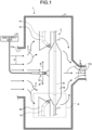
- FIG. 1 illustrates an outside vapor deposition (OVD) apparatus, which is a manufacturing apparatus for an optical fiber porous preform according to this embodiment.
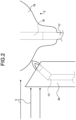
- FIG. 2 is an enlarged view of an enclosed portion A in FIG. 1 .
- ODD outside vapor deposition
- an OVD apparatus 1 includes a reaction chamber 11, a glass-particulate synthesizing burner 12, an auxiliary burner 13 on which a wind guard 20 is arranged, an auxiliary burner 14 on which a wind guard 21 is arranged, and a gas supply unit 15.
- the reaction chamber 11 is configured to be able to carry in and accommodate a target 16 and dummy rods 17.
- an air inlet 11a for introducing clean air from the outside or a predetermined air supply unit (not depicted), and an exhaust duct 11b for discharging gas in the reaction chamber 11.
- airflow 3 going toward the exhaust duct 11b from the air inlet 11a is generated in the reaction chamber 11.
- the surplus glass particulates floating in the reaction chamber 11 during the manufacturing of a porous preform 2 can be discharged from the exhaust duct 11b.
- the glass-particulate synthesizing burner 12 which is a main burner, is made up of at least a single concentric multi-tube burner for depositing glass particulates on the target 16 as a starting material, or for performing sintering.
- a main raw material gas such as silicon tetrachloride (SiCl 4 ), hydrogen (H 2 ) gas, which is a flammable gas, oxygen (O 2 ) gas, which is a combustion supporting gas, argon (Ar) gas as a blanketing gas, or the like, for example.
- the dummy rods 17 are portions that are connected to both ends of the target 16 and are grasped by grasping units (not depicted) for driving to rotate and driving to elevate the target 16.
- a gas composed of vaporized SiCl 4 gas, H 2 gas, and O 2 gas is supplied while being ignited and burned in the glass-particulate synthesizing burner 12.
- the SiCl 4 that is subjected to hydrolysis reaction in the flames is turned into silica particulates and deposited around the target 16.
- the glass-particulate synthesizing burner 12 is made to repeatedly reciprocate along the longitudinal direction of the target 16 (arrows B in FIG. 1 ).
- the glass particulates are uniformly deposited on the outer circumference of the target 16, and a porous layer 18 in the porous preform 2 is formed.
- the target 16 is made up of a portion to be a core when made into an optical fiber, and a portion to be a cladding formed therearound.
- the porous layer 18 turns into a cladding portion that is integrated with a portion to be the cladding of the target 16 when made into an optical fiber later.
- each of the auxiliary burners 13 and 14 is provided in the vicinity of the end portion along the longitudinal direction of the target 16.
- the positions of the auxiliary burners 13 and 14 are immovable with respect to the end portions of the target 16.
- This configuration enables the auxiliary burners 13 and 14 to be able to heat both end portions of the porous preform 2 to be manufactured.
- a flammable gas such as H 2 gas and a combustion supporting gas such as O 2 gas are introduced, for example.
- the flammable gas and the combustion supporting gas are ignited and burned in the auxiliary burners 13 and 14, and the end portions of the target 16 are heated.
- FIG. 3 and FIG. 4 are respectively a side view and a top view of the wind guards 20 and 21 in this embodiment.
- the wind guards 20 and 21 serving as an airflow guiding unit in this embodiment are respectively provided in the vicinity of the auxiliary burners 13 and 14.
- the wind guards 20 and 21 at least an emission side of the flames is open that the auxiliary burners 13 and 14 emit.
- each of the wind guards 20 and 21 has a shape covering, with respect to the auxiliary burners 13 and 14, the side opposite to the emission side of the flames, and lateral sides as viewed from the emission side.
- the shape of the wind guards 20 and 21 in a lateral view see FIG.
- a lateral surface shape seen from the plane in FIG. 2 (hereinafter referred to as a lateral surface shape) is in a trapezoidal shape having a tapered portion corresponding to the shape of the end portion of the porous preform 2.
- the shape of the wind guards 20 and 21 in FIG. 2 in top view (see FIG. 4 ) seen from the upper portion (hereinafter referred to as an upper surface shape) is in a U-shape that covers and guards the lateral sides of the auxiliary burners 13 and 14.
- the wind guards 20 and 21 are made of titanium (Ti) or a Ti alloy, for example.
- Ti and Ti alloys are preferable, from the viewpoint of being excellent in corrosion resistance and durability, as the material of the wind guards 20 and 21 that are arranged in the vicinity of the auxiliary burners 13 and 14.
- materials such as quartz glass, which is excellent in corrosion resistance and heat resistance and is easy to process.
- the wind guard 20 is located on the upstream side of the airflow 3 generated in the reaction chamber 11 and, on the downstream side of the airflow, the open portion of the wind guard 20 is located. As a result, it is configured such that the airflow 3 does not directly blow against the auxiliary burner 13. Furthermore, as illustrated in FIG. 4 , as the airflow 3 is guided by lateral surfaces 20a of the wind guard 20 on the lateral sides of the auxiliary burner 13, the airflow 3 can be restrained from going around toward the open portion of the wind guard 20. This configuration prevents the airflow 3 from going toward the flames of the auxiliary burner 13.
- the flames of the auxiliary burner 13 can be restrained from being fanned greatly by the airflow 3, and the flames can be stabilized.
- the gas flow rate of the glass-particulate synthesizing burner 12 is larger as compared with the auxiliary burners 13 and 14, the possibility of being fanned greatly by the airflow 3 is low.
- FIG. 5 is a side view illustrating a wind guard 22 according to a first modification of the present invention.
- the lateral surface shape of the wind guard 22 in the first modification is in a rectangular shape, for example.
- FIG. 6 is a side view illustrating a wind guard 23 according to a second modification of the present invention.
- the lateral surface shape of the wind guard 23 in the second modification is a tetragon for which the upper portion has a tapered shape corresponding to the shape of the end portion of the porous preform 2 and the side on the porous preform 2 side of the wind guard 23 has a tapered shape expanding toward the lower portion.
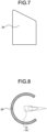
- FIG. 7 is a side view illustrating a wind guard 24 according to a third modification of the present invention.
- the lateral surface shape of the wind guard 24 in the third modification has a shape for which the corner of the upper portion in the lateral surface shape of the wind guard 20 in the above-described embodiment is rounded.
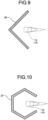
- FIG. 9 is a top view of a wind guard 26 according to a fifth modification of the present invention.
- the upper surface shape of the wind guard 26 in the fifth modification has an L-shape for which the emission side of the flames from the auxiliary burner 13 or 14 is open and has a shape covering, with respect to the auxiliary burner 13 or 14, the side opposite to the emission side, and the lateral sides as viewed from the emission side.
- the embodiment of the present invention in the foregoing enables the wind guards 20 and 21 serving as an airflow guiding unit to prevent the airflow 3 in the reaction chamber 11 from directly blowing against the flames of the auxiliary burner 13, and thus the flames are not greatly fanned by the airflow 3 are stabilized, the sintering of the end portions of the porous preform 2 can be performed sufficiently.
- the occurrence of cracks in the porous preform 2 can be suppressed.
- SiCl 4 As the glass material, SiHCl 3 , SiHCl 2 , and the like may be used, for example, and for Ge raw material as a dopant, GeCl 4 may further be used. Moreover, a glass material such as siloxane may be used. Furthermore, as the flammable gas, in addition to H 2 , a short-chain hydrocarbon such as CH 4 , C 2 H 6 , C 3 H 8 , C 4 H 10 , and the like may be used, for example.
- a short-chain hydrocarbon such as CH 4 , C 2 H 6 , C 3 H 8 , C 4 H 10 , and the like may be used, for example.
- the glass-particulate synthesizing burner 12 has been made to reciprocate along the longitudinal direction of the target 16.
- the glass-particulate synthesizing burner 12 and the porous preform 2 only need to reciprocate relatively, and the porous preform 2 can be made to reciprocate with the glass-particulate synthesizing burner 12 standing still.
Landscapes
- Chemical & Material Sciences (AREA)
- Engineering & Computer Science (AREA)
- Chemical Kinetics & Catalysis (AREA)
- General Chemical & Material Sciences (AREA)
- Life Sciences & Earth Sciences (AREA)
- General Life Sciences & Earth Sciences (AREA)
- Geochemistry & Mineralogy (AREA)
- Manufacturing & Machinery (AREA)
- Materials Engineering (AREA)
- Organic Chemistry (AREA)
- Manufacture, Treatment Of Glass Fibers (AREA)
Claims (3)
- Herstellungsvorrichtung für einen porösen Vorformling für optische Fasern, umfassend:eine Reaktionskammer (11) mit einem Lufteinlass (11a) und einem Abluftkanal (11b);eine Gasversorgungseinheit (15), die ein Rohmaterialgas und ein brennbares Gas liefert;mindestens einen Hauptbrenner (12), der in der Reaktionskammer (11) vorgesehen ist und das brennbare Gas und das Rohmaterialgas entzündet und verbrennt, um Glaspartikel zu synthetisieren, und die synthetisierten Glaspartikel einem Ausgangsmaterial (16) zuführt, während er relativ zum Ausgangsmaterial (16) bewegt wird, um die durch die Reaktion der Gase erzeugten Partikel auf einem Außenumfang des Ausgangsmaterials (16) abzulagern und so einen porösen Vorformling (2) zu bilden; undmindestens einen Hilfsbrenner (13), der einen Endabschnitt des porösen Vorformlings erhitzt, wobei eine Position des Hilfsbrenners (13) in Bezug auf das Ausgangsmaterial (16) unbeweglich ist,dadurch gekennzeichnet, dassdie Herstellungsvorrichtung ferner eine Luftstromführungseinheit (20) umfasst, die verhindert, dass ein Luftstrom vom Lufteinlass (11a) zum Abluftkanal (11b) direkt gegen den Hilfsbrenner (13) bläst, wobei die Luftstromführungseinheit (20) in der Nähe des Hilfsbrenners (13) vorgesehen ist,die Luftstromführungseinheit (20) eine Form, für die eine Emissionsseite von Flammen, die der Hilfsbrenner (13) emittiert, offen ist, und eine Form, die in Bezug auf den Hilfsbrenner (13) eine Seite abdeckt, die der Emissionsseite gegenüberliegt, und von der Emissionsseite aus gesehen seitliche Seiten hat,ein offener Abschnitt der Luftstromführungseinheit auf einer Seite des Abgaskanals (11b) eines in der Reaktionskammer (11) erzeugten Luftstroms angeordnet ist.
- Herstellungsvorrichtung für einen porösen Vorformling für optische Fasern nach Anspruch 1, wobei der Hilfsbrenner (13) in der Nähe eines Endabschnitts entlang einer Längsrichtung des Ausgangsmaterials (16) vorgesehen ist.
- Herstellungsverfahren für einen porösen Vorformling für optische Fasern, bei dem in einer Reaktionskammer (11) mit einem Lufteinlass (11a) und einem Abluftkanal (11b) ein poröser Vorformling (2) gebildet wird, indem ein Hauptbrenner (12) relativ zu einem Ausgangsmaterial (16) bewegt wird (16) bewegt wird, während dem Ausgangsmaterial (16) vom Hauptbrenner (12) aus ein Gas zugeführt wird, das ein brennbares Gas und ein Rohmaterialgas enthält, und durch Abscheiden von Partikeln, die durch Reaktion der Gase erzeugt werden, auf einem Außenumfang des Ausgangsmaterials (16), wobei das Herstellungsverfahren umfasst:
Erhitzen eines Endabschnitts des porösen Vorformlings (2) durch einen Hilfsbrenner (13), wobei eine Position des Hilfsbrenners (13) in Bezug auf das Ausgangsmaterial (16) unbeweglich ist, wobei das Verfahren dadurch gekennzeichnet ist, dass:eine Luftstromführungseinheit (20) in der Nähe des Hilfsbrenners (13), der Flammen emittiert, vorgesehen ist, wobei die Luftstromführungseinheit (20) eine Form hat, für die eine Emissionsseite von Flammen, die der Hilfsbrenner (13) emittiert, offen ist, und eine Form, die in Bezug auf den Hilfsbrenner (13) eine Seite gegenüber der Emissionsseite und Seitenflächen, von der Emissionsseite aus gesehen, abdeckt,ein offener Abschnitt der Luftstromführungseinheit (20) auf der Seite eines Abgaskanals (11b) eines in der Reaktionskammer (11) erzeugten Luftstroms angeordnet ist, unddie Luftstromführungseinheit (20) verhindert, dass ein Luftstrom vom Lufteinlass (11a) von der Seite, die der Emissionsseite der Flammen des Hilfsbrenners (13) gegenüberliegt, und von den Querseiten, von der Emissionsseite aus gesehen, zu den Flammen strömt.
Applications Claiming Priority (2)
| Application Number | Priority Date | Filing Date | Title |
|---|---|---|---|
| JP2017068857A JP6839586B2 (ja) | 2017-03-30 | 2017-03-30 | 光ファイバ多孔質母材の製造装置及び製造方法 |
| PCT/JP2018/009968 WO2018180495A1 (ja) | 2017-03-30 | 2018-03-14 | 光ファイバ多孔質母材の製造装置及び製造方法 |
Publications (3)
| Publication Number | Publication Date |
|---|---|
| EP3608296A1 EP3608296A1 (de) | 2020-02-12 |
| EP3608296A4 EP3608296A4 (de) | 2021-01-06 |
| EP3608296B1 true EP3608296B1 (de) | 2025-03-05 |
Family
ID=63676948
Family Applications (1)
| Application Number | Title | Priority Date | Filing Date |
|---|---|---|---|
| EP18774435.4A Active EP3608296B1 (de) | 2017-03-30 | 2018-03-14 | Herstellungsvorrichtung und herstellungsverfahren für poröse glasfaservorform |
Country Status (5)
| Country | Link |
|---|---|
| US (1) | US11820691B2 (de) |
| EP (1) | EP3608296B1 (de) |
| JP (1) | JP6839586B2 (de) |
| CN (1) | CN110461783B (de) |
| WO (1) | WO2018180495A1 (de) |
Families Citing this family (1)
| Publication number | Priority date | Publication date | Assignee | Title |
|---|---|---|---|---|
| KR102636792B1 (ko) * | 2023-07-05 | 2024-02-15 | 비씨엔씨 주식회사 | 배기기능 개선을 통해 증착물의 표면결함을 방지할수 있는 합성쿼츠 제조설비 |
Citations (1)
| Publication number | Priority date | Publication date | Assignee | Title |
|---|---|---|---|---|
| US20020162363A1 (en) * | 2001-05-02 | 2002-11-07 | The Furukawa Electric Co., Ltd. | Apparatus for manufacturing an optical fiber soot, and method for manufacturing an optical fiber soot using thereof |
Family Cites Families (19)
| Publication number | Priority date | Publication date | Assignee | Title |
|---|---|---|---|---|
| JPS60137839A (ja) * | 1983-12-23 | 1985-07-22 | Furukawa Electric Co Ltd:The | 光学系ガラス微粉末生成用バ−ナ |
| US4810276A (en) * | 1987-08-05 | 1989-03-07 | Corning Glass Works | Forming optical fiber having abrupt index change |
| JPH04193730A (ja) * | 1990-11-26 | 1992-07-13 | Fujikura Ltd | 光ファイバ母材の製造方法および酸水素バーナ用フード |
| DE19628958C2 (de) * | 1996-07-18 | 2000-02-24 | Heraeus Quarzglas | Verfahren zur Herstellung von Quarzglaskörpern |
| JP3524426B2 (ja) * | 1999-04-02 | 2004-05-10 | 古河電気工業株式会社 | 多孔質光ファイバ母材の製造装置 |
| JP2001354430A (ja) * | 2000-06-07 | 2001-12-25 | Sumitomo Electric Ind Ltd | ガラス物品の製造方法 |
| US20050120752A1 (en) * | 2001-04-11 | 2005-06-09 | Brown John T. | Substantially dry, silica-containing soot, fused silica and optical fiber soot preforms, apparatus, methods and burners for manufacturing same |
| DE60239504D1 (de) | 2001-05-08 | 2011-05-05 | Shinetsu Chemical Co | Vorrichtung und Verfahren zum Herstellen von einer Vorform für optische Fasern durch Abscheidung |
| JP2003165738A (ja) | 2001-11-29 | 2003-06-10 | Shin Etsu Chem Co Ltd | サイドバーナの位置微調整方法及び光ファイバ用母材の製造装置 |
| US20040123630A1 (en) * | 2001-07-17 | 2004-07-01 | Arnab Sarkar | Preform fabrication process |
| JP2004269284A (ja) * | 2003-03-05 | 2004-09-30 | Sumitomo Electric Ind Ltd | 多孔質ガラス材料の製造法、並びに外径変動の少ないガラス材料 |
| JP2006264995A (ja) * | 2005-03-22 | 2006-10-05 | Hitachi Cable Ltd | 光ファイバ用母材製造装置及び製造方法 |
| JP4434083B2 (ja) * | 2005-06-13 | 2010-03-17 | 住友電気工業株式会社 | ガラス微粒子堆積体の製造装置及び製造方法 |
| WO2007054961A2 (en) * | 2005-09-05 | 2007-05-18 | Sterlite Optical Technologies Ltd. | Optical fiber preform having large size soot porous body and its method of preparation |
| JP2010042940A (ja) * | 2008-08-08 | 2010-02-25 | Sumitomo Electric Ind Ltd | ガラス母材の製造装置及び製造方法 |
| JP5416076B2 (ja) * | 2010-12-03 | 2014-02-12 | 古河電気工業株式会社 | 光ファイバ母材の製造方法 |
| JP5566929B2 (ja) * | 2011-03-16 | 2014-08-06 | 古河電気工業株式会社 | 光ファイバ母材の製造方法、および光ファイバ母材の製造装置 |
| CN103803789B (zh) * | 2012-11-06 | 2016-12-21 | 浙江富通光纤技术有限公司 | 一种预制棒头形沉积的方法及装置 |
| CN204588997U (zh) * | 2015-04-23 | 2015-08-26 | 浙江富通光纤技术有限公司 | 一种光纤预制棒的烧结喷灯 |
-
2017
- 2017-03-30 JP JP2017068857A patent/JP6839586B2/ja active Active
-
2018
- 2018-03-14 CN CN201880020381.6A patent/CN110461783B/zh active Active
- 2018-03-14 EP EP18774435.4A patent/EP3608296B1/de active Active
- 2018-03-14 WO PCT/JP2018/009968 patent/WO2018180495A1/ja not_active Ceased
-
2019
- 2019-09-24 US US16/580,364 patent/US11820691B2/en active Active
Patent Citations (1)
| Publication number | Priority date | Publication date | Assignee | Title |
|---|---|---|---|---|
| US20020162363A1 (en) * | 2001-05-02 | 2002-11-07 | The Furukawa Electric Co., Ltd. | Apparatus for manufacturing an optical fiber soot, and method for manufacturing an optical fiber soot using thereof |
Also Published As
| Publication number | Publication date |
|---|---|
| CN110461783B (zh) | 2022-09-02 |
| EP3608296A1 (de) | 2020-02-12 |
| US11820691B2 (en) | 2023-11-21 |
| JP2018168049A (ja) | 2018-11-01 |
| WO2018180495A1 (ja) | 2018-10-04 |
| EP3608296A4 (de) | 2021-01-06 |
| US20200017396A1 (en) | 2020-01-16 |
| CN110461783A (zh) | 2019-11-15 |
| JP6839586B2 (ja) | 2021-03-10 |
Similar Documents
| Publication | Publication Date | Title |
|---|---|---|
| EP2248775B1 (de) | Brenner zur herstellung von porösem glasbasismaterial | |
| JP6236866B2 (ja) | ガラス微粒子堆積体の製造方法およびガラス微粒子堆積体製造用バーナー | |
| JPH039047B2 (de) | ||
| CN103011579B (zh) | 一种大尺寸光纤预制棒的在线退火装置及其在线退火方法 | |
| JP2020114801A (ja) | 改良された粒子蒸着システムと方法 | |
| CN102234178A (zh) | 用于制造多孔玻璃预型体的燃烧器 | |
| RU2284968C2 (ru) | Способ изготовления оптического стекла | |
| US11820691B2 (en) | Manufacturing apparatus and manufacturing method for optical fiber porous preform | |
| KR100508707B1 (ko) | 외부 기상증착에 의한 프리폼 제조방법 및 제조장치 | |
| EP2221281B1 (de) | Brenner zur Herstellung von porösem Glasbasismaterial und Verfahren zur Herstellung von porösem Glasbasismaterial | |
| US7441417B2 (en) | Outside vapor deposition apparatus for making optical fiber preform | |
| US9227869B2 (en) | Porous glass base material manufacturing burner and optical fiber porous glass base material manufacturing apparatus | |
| KR102545709B1 (ko) | 광섬유용 다공질 유리 퇴적체의 제조 방법 | |
| JP4348341B2 (ja) | 光ファイバ母材の製造方法 | |
| JP5414611B2 (ja) | 多孔質ガラス母材製造用バーナ | |
| JPS5983953A (ja) | 光フアイバ母材の製造方法 | |
| KR100630117B1 (ko) | 기상 외부 증착 방법에 의한 광섬유 모재 제작 장치 | |
| CN203065348U (zh) | 一种大尺寸光纤预制棒的在线退火装置 | |
| JP7763116B2 (ja) | 光ファイバ母材の製造方法および光ファイバの製造方法 | |
| JP6284516B2 (ja) | 光ファイバ母材の製造方法、および光ファイバ母材の製造装置 | |
| JP5907565B2 (ja) | 多孔質ガラス母材製造用のバーナ | |
| US20220017403A1 (en) | Burner for producing glass fine particle deposited body, and device and method for producing glass fine particle deposited body | |
| JP2024014098A (ja) | 光ファイバ母材の製造装置、製造方法、光ファイバ母材および光ファイバ | |
| JP2024030361A (ja) | ガラス母材の製造方法 | |
| HK40057103A (en) | Enhanced particle deposition system and method |
Legal Events
| Date | Code | Title | Description |
|---|---|---|---|
| STAA | Information on the status of an ep patent application or granted ep patent |
Free format text: STATUS: THE INTERNATIONAL PUBLICATION HAS BEEN MADE |
|
| PUAI | Public reference made under article 153(3) epc to a published international application that has entered the european phase |
Free format text: ORIGINAL CODE: 0009012 |
|
| STAA | Information on the status of an ep patent application or granted ep patent |
Free format text: STATUS: REQUEST FOR EXAMINATION WAS MADE |
|
| 17P | Request for examination filed |
Effective date: 20190924 |
|
| AK | Designated contracting states |
Kind code of ref document: A1 Designated state(s): AL AT BE BG CH CY CZ DE DK EE ES FI FR GB GR HR HU IE IS IT LI LT LU LV MC MK MT NL NO PL PT RO RS SE SI SK SM TR |
|
| AX | Request for extension of the european patent |
Extension state: BA ME |
|
| DAV | Request for validation of the european patent (deleted) | ||
| DAX | Request for extension of the european patent (deleted) | ||
| REG | Reference to a national code |
Ref country code: DE Ref legal event code: R079 Free format text: PREVIOUS MAIN CLASS: C03B0037018000 Ipc: C03B0037014000 |
|
| A4 | Supplementary search report drawn up and despatched |
Effective date: 20201204 |
|
| RIC1 | Information provided on ipc code assigned before grant |
Ipc: C03B 37/014 20060101AFI20201130BHEP |
|
| STAA | Information on the status of an ep patent application or granted ep patent |
Free format text: STATUS: EXAMINATION IS IN PROGRESS |
|
| 17Q | First examination report despatched |
Effective date: 20230707 |
|
| GRAP | Despatch of communication of intention to grant a patent |
Free format text: ORIGINAL CODE: EPIDOSNIGR1 |
|
| STAA | Information on the status of an ep patent application or granted ep patent |
Free format text: STATUS: GRANT OF PATENT IS INTENDED |
|
| INTG | Intention to grant announced |
Effective date: 20241009 |
|
| P01 | Opt-out of the competence of the unified patent court (upc) registered |
Free format text: CASE NUMBER: APP_62790/2024 Effective date: 20241126 |
|
| GRAS | Grant fee paid |
Free format text: ORIGINAL CODE: EPIDOSNIGR3 |
|
| GRAA | (expected) grant |
Free format text: ORIGINAL CODE: 0009210 |
|
| STAA | Information on the status of an ep patent application or granted ep patent |
Free format text: STATUS: THE PATENT HAS BEEN GRANTED |
|
| AK | Designated contracting states |
Kind code of ref document: B1 Designated state(s): AL AT BE BG CH CY CZ DE DK EE ES FI FR GB GR HR HU IE IS IT LI LT LU LV MC MK MT NL NO PL PT RO RS SE SI SK SM TR |
|
| REG | Reference to a national code |
Ref country code: GB Ref legal event code: FG4D |
|
| REG | Reference to a national code |
Ref country code: CH Ref legal event code: EP |
|
| REG | Reference to a national code |
Ref country code: IE Ref legal event code: FG4D |
|
| REG | Reference to a national code |
Ref country code: DE Ref legal event code: R096 Ref document number: 602018079829 Country of ref document: DE |
|
| PG25 | Lapsed in a contracting state [announced via postgrant information from national office to epo] |
Ref country code: RS Free format text: LAPSE BECAUSE OF FAILURE TO SUBMIT A TRANSLATION OF THE DESCRIPTION OR TO PAY THE FEE WITHIN THE PRESCRIBED TIME-LIMIT Effective date: 20250605 |
|
| PG25 | Lapsed in a contracting state [announced via postgrant information from national office to epo] |
Ref country code: FI Free format text: LAPSE BECAUSE OF FAILURE TO SUBMIT A TRANSLATION OF THE DESCRIPTION OR TO PAY THE FEE WITHIN THE PRESCRIBED TIME-LIMIT Effective date: 20250305 |
|
| REG | Reference to a national code |
Ref country code: NL Ref legal event code: MP Effective date: 20250305 |
|
| PG25 | Lapsed in a contracting state [announced via postgrant information from national office to epo] |
Ref country code: ES Free format text: LAPSE BECAUSE OF FAILURE TO SUBMIT A TRANSLATION OF THE DESCRIPTION OR TO PAY THE FEE WITHIN THE PRESCRIBED TIME-LIMIT Effective date: 20250305 |
|
| REG | Reference to a national code |
Ref country code: LT Ref legal event code: MG9D |
|
| PG25 | Lapsed in a contracting state [announced via postgrant information from national office to epo] |
Ref country code: NO Free format text: LAPSE BECAUSE OF FAILURE TO SUBMIT A TRANSLATION OF THE DESCRIPTION OR TO PAY THE FEE WITHIN THE PRESCRIBED TIME-LIMIT Effective date: 20250605 |
|
| PG25 | Lapsed in a contracting state [announced via postgrant information from national office to epo] |
Ref country code: HR Free format text: LAPSE BECAUSE OF FAILURE TO SUBMIT A TRANSLATION OF THE DESCRIPTION OR TO PAY THE FEE WITHIN THE PRESCRIBED TIME-LIMIT Effective date: 20250305 |
|
| PG25 | Lapsed in a contracting state [announced via postgrant information from national office to epo] |
Ref country code: LV Free format text: LAPSE BECAUSE OF FAILURE TO SUBMIT A TRANSLATION OF THE DESCRIPTION OR TO PAY THE FEE WITHIN THE PRESCRIBED TIME-LIMIT Effective date: 20250305 |
|
| PG25 | Lapsed in a contracting state [announced via postgrant information from national office to epo] |
Ref country code: GR Free format text: LAPSE BECAUSE OF FAILURE TO SUBMIT A TRANSLATION OF THE DESCRIPTION OR TO PAY THE FEE WITHIN THE PRESCRIBED TIME-LIMIT Effective date: 20250606 Ref country code: BG Free format text: LAPSE BECAUSE OF FAILURE TO SUBMIT A TRANSLATION OF THE DESCRIPTION OR TO PAY THE FEE WITHIN THE PRESCRIBED TIME-LIMIT Effective date: 20250305 |
|
| REG | Reference to a national code |
Ref country code: AT Ref legal event code: MK05 Ref document number: 1772846 Country of ref document: AT Kind code of ref document: T Effective date: 20250305 |
|
| PG25 | Lapsed in a contracting state [announced via postgrant information from national office to epo] |
Ref country code: NL Free format text: LAPSE BECAUSE OF FAILURE TO SUBMIT A TRANSLATION OF THE DESCRIPTION OR TO PAY THE FEE WITHIN THE PRESCRIBED TIME-LIMIT Effective date: 20250305 |
|
| PG25 | Lapsed in a contracting state [announced via postgrant information from national office to epo] |
Ref country code: SE Free format text: LAPSE BECAUSE OF FAILURE TO SUBMIT A TRANSLATION OF THE DESCRIPTION OR TO PAY THE FEE WITHIN THE PRESCRIBED TIME-LIMIT Effective date: 20250305 |
|
| PG25 | Lapsed in a contracting state [announced via postgrant information from national office to epo] |
Ref country code: SM Free format text: LAPSE BECAUSE OF FAILURE TO SUBMIT A TRANSLATION OF THE DESCRIPTION OR TO PAY THE FEE WITHIN THE PRESCRIBED TIME-LIMIT Effective date: 20250305 |
|
| PG25 | Lapsed in a contracting state [announced via postgrant information from national office to epo] |
Ref country code: PT Free format text: LAPSE BECAUSE OF FAILURE TO SUBMIT A TRANSLATION OF THE DESCRIPTION OR TO PAY THE FEE WITHIN THE PRESCRIBED TIME-LIMIT Effective date: 20250707 |
|
| PG25 | Lapsed in a contracting state [announced via postgrant information from national office to epo] |
Ref country code: IT Free format text: LAPSE BECAUSE OF FAILURE TO SUBMIT A TRANSLATION OF THE DESCRIPTION OR TO PAY THE FEE WITHIN THE PRESCRIBED TIME-LIMIT Effective date: 20250305 Ref country code: PL Free format text: LAPSE BECAUSE OF FAILURE TO SUBMIT A TRANSLATION OF THE DESCRIPTION OR TO PAY THE FEE WITHIN THE PRESCRIBED TIME-LIMIT Effective date: 20250305 |
|
| PG25 | Lapsed in a contracting state [announced via postgrant information from national office to epo] |
Ref country code: AT Free format text: LAPSE BECAUSE OF FAILURE TO SUBMIT A TRANSLATION OF THE DESCRIPTION OR TO PAY THE FEE WITHIN THE PRESCRIBED TIME-LIMIT Effective date: 20250305 |
|
| PG25 | Lapsed in a contracting state [announced via postgrant information from national office to epo] |
Ref country code: EE Free format text: LAPSE BECAUSE OF FAILURE TO SUBMIT A TRANSLATION OF THE DESCRIPTION OR TO PAY THE FEE WITHIN THE PRESCRIBED TIME-LIMIT Effective date: 20250305 Ref country code: CZ Free format text: LAPSE BECAUSE OF FAILURE TO SUBMIT A TRANSLATION OF THE DESCRIPTION OR TO PAY THE FEE WITHIN THE PRESCRIBED TIME-LIMIT Effective date: 20250305 |
|
| REG | Reference to a national code |
Ref country code: CH Ref legal event code: H13 Free format text: ST27 STATUS EVENT CODE: U-0-0-H10-H13 (AS PROVIDED BY THE NATIONAL OFFICE) Effective date: 20251023 |
|
| PG25 | Lapsed in a contracting state [announced via postgrant information from national office to epo] |
Ref country code: RO Free format text: LAPSE BECAUSE OF FAILURE TO SUBMIT A TRANSLATION OF THE DESCRIPTION OR TO PAY THE FEE WITHIN THE PRESCRIBED TIME-LIMIT Effective date: 20250305 |
|
| PG25 | Lapsed in a contracting state [announced via postgrant information from national office to epo] |
Ref country code: SK Free format text: LAPSE BECAUSE OF FAILURE TO SUBMIT A TRANSLATION OF THE DESCRIPTION OR TO PAY THE FEE WITHIN THE PRESCRIBED TIME-LIMIT Effective date: 20250305 |
|
| PG25 | Lapsed in a contracting state [announced via postgrant information from national office to epo] |
Ref country code: IS Free format text: LAPSE BECAUSE OF FAILURE TO SUBMIT A TRANSLATION OF THE DESCRIPTION OR TO PAY THE FEE WITHIN THE PRESCRIBED TIME-LIMIT Effective date: 20250705 |
|
| PG25 | Lapsed in a contracting state [announced via postgrant information from national office to epo] |
Ref country code: LU Free format text: LAPSE BECAUSE OF NON-PAYMENT OF DUE FEES Effective date: 20250314 |
|
| REG | Reference to a national code |
Ref country code: DE Ref legal event code: R097 Ref document number: 602018079829 Country of ref document: DE |
|
| REG | Reference to a national code |
Ref country code: BE Ref legal event code: MM Effective date: 20250331 |
|
| PG25 | Lapsed in a contracting state [announced via postgrant information from national office to epo] |
Ref country code: MC Free format text: LAPSE BECAUSE OF FAILURE TO SUBMIT A TRANSLATION OF THE DESCRIPTION OR TO PAY THE FEE WITHIN THE PRESCRIBED TIME-LIMIT Effective date: 20250305 |
|
| PLBE | No opposition filed within time limit |
Free format text: ORIGINAL CODE: 0009261 |
|
| STAA | Information on the status of an ep patent application or granted ep patent |
Free format text: STATUS: NO OPPOSITION FILED WITHIN TIME LIMIT |
|
| PG25 | Lapsed in a contracting state [announced via postgrant information from national office to epo] |
Ref country code: DK Free format text: LAPSE BECAUSE OF FAILURE TO SUBMIT A TRANSLATION OF THE DESCRIPTION OR TO PAY THE FEE WITHIN THE PRESCRIBED TIME-LIMIT Effective date: 20250305 |
|
| REG | Reference to a national code |
Ref country code: CH Ref legal event code: L10 Free format text: ST27 STATUS EVENT CODE: U-0-0-L10-L00 (AS PROVIDED BY THE NATIONAL OFFICE) Effective date: 20260114 |
|
| PG25 | Lapsed in a contracting state [announced via postgrant information from national office to epo] |
Ref country code: BE Free format text: LAPSE BECAUSE OF NON-PAYMENT OF DUE FEES Effective date: 20250331 |
|
| PG25 | Lapsed in a contracting state [announced via postgrant information from national office to epo] |
Ref country code: CH Free format text: LAPSE BECAUSE OF NON-PAYMENT OF DUE FEES Effective date: 20250331 |
|
| PG25 | Lapsed in a contracting state [announced via postgrant information from national office to epo] |
Ref country code: IE Free format text: LAPSE BECAUSE OF NON-PAYMENT OF DUE FEES Effective date: 20250314 |
|
| 26N | No opposition filed |
Effective date: 20251208 |
|
| PGFP | Annual fee paid to national office [announced via postgrant information from national office to epo] |
Ref country code: GB Payment date: 20260202 Year of fee payment: 9 |
|
| PGFP | Annual fee paid to national office [announced via postgrant information from national office to epo] |
Ref country code: DE Payment date: 20260128 Year of fee payment: 9 |
|
| PGFP | Annual fee paid to national office [announced via postgrant information from national office to epo] |
Ref country code: FR Payment date: 20260209 Year of fee payment: 9 |