EP3604088B1 - Fahrzeugkarosserie und fahrzeug - Google Patents
Fahrzeugkarosserie und fahrzeug Download PDFInfo
- Publication number
- EP3604088B1 EP3604088B1 EP18775111.0A EP18775111A EP3604088B1 EP 3604088 B1 EP3604088 B1 EP 3604088B1 EP 18775111 A EP18775111 A EP 18775111A EP 3604088 B1 EP3604088 B1 EP 3604088B1
- Authority
- EP
- European Patent Office
- Prior art keywords
- longitudinal beam
- floor
- bracket
- dash
- vehicle body
- Prior art date
- Legal status (The legal status is an assumption and is not a legal conclusion. Google has not performed a legal analysis and makes no representation as to the accuracy of the status listed.)
- Active
Links
Images






Classifications
-
- B—PERFORMING OPERATIONS; TRANSPORTING
- B62—LAND VEHICLES FOR TRAVELLING OTHERWISE THAN ON RAILS
- B62D—MOTOR VEHICLES; TRAILERS
- B62D27/00—Connections between superstructure or understructure sub-units
- B62D27/02—Connections between superstructure or understructure sub-units rigid
- B62D27/023—Assembly of structural joints
-
- B—PERFORMING OPERATIONS; TRANSPORTING
- B62—LAND VEHICLES FOR TRAVELLING OTHERWISE THAN ON RAILS
- B62D—MOTOR VEHICLES; TRAILERS
- B62D21/00—Understructures, i.e. chassis frame on which a vehicle body may be mounted
- B62D21/15—Understructures, i.e. chassis frame on which a vehicle body may be mounted having impact absorbing means, e.g. a frame designed to permanently or temporarily change shape or dimension upon impact with another body
- B62D21/152—Front or rear frames
- B62D21/155—Sub-frames or underguards
-
- B—PERFORMING OPERATIONS; TRANSPORTING
- B62—LAND VEHICLES FOR TRAVELLING OTHERWISE THAN ON RAILS
- B62D—MOTOR VEHICLES; TRAILERS
- B62D21/00—Understructures, i.e. chassis frame on which a vehicle body may be mounted
- B62D21/15—Understructures, i.e. chassis frame on which a vehicle body may be mounted having impact absorbing means, e.g. a frame designed to permanently or temporarily change shape or dimension upon impact with another body
- B62D21/157—Understructures, i.e. chassis frame on which a vehicle body may be mounted having impact absorbing means, e.g. a frame designed to permanently or temporarily change shape or dimension upon impact with another body for side impacts
-
- B—PERFORMING OPERATIONS; TRANSPORTING
- B62—LAND VEHICLES FOR TRAVELLING OTHERWISE THAN ON RAILS
- B62D—MOTOR VEHICLES; TRAILERS
- B62D25/00—Superstructure or monocoque structure sub-units; Parts or details thereof not otherwise provided for
- B62D25/08—Front or rear portions
-
- B—PERFORMING OPERATIONS; TRANSPORTING
- B62—LAND VEHICLES FOR TRAVELLING OTHERWISE THAN ON RAILS
- B62D—MOTOR VEHICLES; TRAILERS
- B62D25/00—Superstructure or monocoque structure sub-units; Parts or details thereof not otherwise provided for
- B62D25/20—Floors or bottom sub-units
- B62D25/2009—Floors or bottom sub-units in connection with other superstructure subunits
- B62D25/2018—Floors or bottom sub-units in connection with other superstructure subunits the subunits being front structures
-
- B—PERFORMING OPERATIONS; TRANSPORTING
- B62—LAND VEHICLES FOR TRAVELLING OTHERWISE THAN ON RAILS
- B62D—MOTOR VEHICLES; TRAILERS
- B62D21/00—Understructures, i.e. chassis frame on which a vehicle body may be mounted
- B62D21/15—Understructures, i.e. chassis frame on which a vehicle body may be mounted having impact absorbing means, e.g. a frame designed to permanently or temporarily change shape or dimension upon impact with another body
- B62D21/152—Front or rear frames
-
- B—PERFORMING OPERATIONS; TRANSPORTING
- B62—LAND VEHICLES FOR TRAVELLING OTHERWISE THAN ON RAILS
- B62D—MOTOR VEHICLES; TRAILERS
- B62D23/00—Combined superstructure and frame, i.e. monocoque constructions
-
- B—PERFORMING OPERATIONS; TRANSPORTING
- B62—LAND VEHICLES FOR TRAVELLING OTHERWISE THAN ON RAILS
- B62D—MOTOR VEHICLES; TRAILERS
- B62D25/00—Superstructure or monocoque structure sub-units; Parts or details thereof not otherwise provided for
- B62D25/08—Front or rear portions
- B62D25/16—Mud-guards or wings; Wheel cover panels
- B62D25/18—Parts or details thereof, e.g. mudguard flaps
-
- B—PERFORMING OPERATIONS; TRANSPORTING
- B62—LAND VEHICLES FOR TRAVELLING OTHERWISE THAN ON RAILS
- B62D—MOTOR VEHICLES; TRAILERS
- B62D25/00—Superstructure or monocoque structure sub-units; Parts or details thereof not otherwise provided for
- B62D25/20—Floors or bottom sub-units
- B62D25/2009—Floors or bottom sub-units in connection with other superstructure subunits
-
- B—PERFORMING OPERATIONS; TRANSPORTING
- B62—LAND VEHICLES FOR TRAVELLING OTHERWISE THAN ON RAILS
- B62D—MOTOR VEHICLES; TRAILERS
- B62D25/00—Superstructure or monocoque structure sub-units; Parts or details thereof not otherwise provided for
- B62D25/20—Floors or bottom sub-units
- B62D25/2009—Floors or bottom sub-units in connection with other superstructure subunits
- B62D25/2027—Floors or bottom sub-units in connection with other superstructure subunits the subunits being rear structures
-
- B—PERFORMING OPERATIONS; TRANSPORTING
- B62—LAND VEHICLES FOR TRAVELLING OTHERWISE THAN ON RAILS
- B62D—MOTOR VEHICLES; TRAILERS
- B62D25/00—Superstructure or monocoque structure sub-units; Parts or details thereof not otherwise provided for
- B62D25/20—Floors or bottom sub-units
- B62D25/2009—Floors or bottom sub-units in connection with other superstructure subunits
- B62D25/2036—Floors or bottom sub-units in connection with other superstructure subunits the subunits being side panels, sills or pillars
-
- B—PERFORMING OPERATIONS; TRANSPORTING
- B62—LAND VEHICLES FOR TRAVELLING OTHERWISE THAN ON RAILS
- B62D—MOTOR VEHICLES; TRAILERS
- B62D25/00—Superstructure or monocoque structure sub-units; Parts or details thereof not otherwise provided for
- B62D25/20—Floors or bottom sub-units
- B62D25/2009—Floors or bottom sub-units in connection with other superstructure subunits
- B62D25/2045—Floors or bottom sub-units in connection with other superstructure subunits the subunits being fire walls
Definitions
- the disclosure relates to a field of vehicle technology, and particularly to a vehicle body and a vehicle having the vehicle body.
- EP2514656A1 discloses a vehicle body floor structure. Stiffeners are connected to the underside portion of the sides of the front portion of a floor panel, and the stiffeners extend to the rear of a front cross member and have upward open U-shaped recesses as seen in the cross section of the vehicle body. Beads are provided in the rear portion of the floor panel, and the beads have U-shaped recesses as seen in the cross section of the vehicle body. The beads are aligned with the recesses of the stiffeners and contiguous with the stiffeners.
- the present disclosure aims to provide a vehicle body to solve the problem of single force transmission path and low force transmission efficiency.
- a vehicle body includes: a front longitudinal beam; a first bracket extending in a left-right direction and having an inner end connected to an outer side of the front longitudinal beam; an upper side beam having a front lower end connected to an outer end of the first bracket, and the front lower end obliquely extending upwards from a front to a rear; a front floor longitudinal beam having a front end connected to a rear end of the front longitudinal beam and having a linear configuration; a rocker panel having a front end connected to a rear end of the front longitudinal beam; and a rear floor longitudinal beam connected to a rear end of the front floor longitudinal beam and a rear end of the rocker panel to make the front floor longitudinal beam, the rocker panel and the rear floor longitudinal beam form a closed-loop force transmission structure.
- the first bracket has a closed cross section.
- the first bracket includes a first bracket plate and a second bracket plate.
- the first bracket plate is in a shape of U.
- the second bracket plate is fixed to an opening of the first bracket plate and seals the opening.
- the upper side beam includes an arc segment and a straight segment.
- the arc segment is connected in front of the straight segment, and a front lower end of the arc segment is fixed to the first bracket.
- the rear floor longitudinal beam includes a front segment, a middle segment, and a rear segment.
- the front segment is connected to the rear end of the front floor longitudinal beam.
- the middle segment is connected to a rear end of the rocker panel, and the rear segment extends backwards from the middle segment.
- a width of the middle segment is larger than a width of the front segment.
- An outer wall of the middle segment abuts an inner wall of the rocker panel and is fixed to the inner wall of the rocker panel.
- the floor centre aisle is provided with a centre aisle force transmission path extending along a front-rear direction.
- the centre aisle force transmission path is a groove.
- a front torsion box is connected between the rocker panel and a rear portion of the front longitudinal beam.
- a centre aisle connecting plate is connected between the floor centre aisle and the rear portion of the front longitudinal beam, and the front torsion box, the front floor longitudinal beam, and the centre aisle connecting plate form a trifurcated structure.
- an impact force transmitted to the front longitudinal beam is transmitted to the rear floor longitudinal beam by means of the front floor longitudinal beam and the rocker panel, and transmitted to the upper side beam by means of the first bracket.
- the first bracket transmits an impact force to the front longitudinal beam to enable the front longitudinal beam deforms towards an outer side of the vehicle.
- an impact force transmitted to the front longitudinal beam is transmitted to the rear floor longitudinal beam by means of the front floor longitudinal beam and the rocker panel, also transmitted to the rear floor longitudinal beam by means of the floor centre aisle and the rear floor cross member, and transmitted to the upper side beam by means of the first bracket.
- the vehicle body according to the present disclosure has the following advantages.
- the vehicle body according to the present disclosure is provided with the first bracket, the front floor longitudinal beam, and the rocker panel, the applied force can be absorbed and resolved quickly and efficiently, thereby effectively dispersing the impact force that is transmitted backwards.
- the intrusive amount of the dash panel can be significantly reduced, which may avoid serious damage to the vehicle body and better ensure a sufficient surviving space for the passenger compartment.
- Another objective of the present disclosure is to provide a vehicle.
- a vehicle includes the above vehicle body.
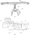
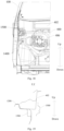
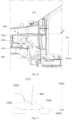
- a vehicle body 10000 of embodiments of the present disclosure will be described in detail as follows with reference to Figs.1-23 and in combination with the embodiments.
- a vehicle body 10000 may include two A-pillars 100, a front impact beam 200, two front longitudinal beams 300, a dash panel 400, a dash upper cross member 402, a dash lower vertical member 403, and two front floor longitudinal beams 500.
- the vehicle body 10000 may also include other components, such as an upper side beam 600, a rocker panel 800, and a rear floor longitudinal beam 900, etc.
- front ends of the two front longitudinal beams 300 are connected at two ends of the front impact beam 200 respectively.
- energy absorbers 201 are arranged between the front ends of the two front longitudinal beams 300 and the two ends of the front impact beam 200.
- the energy absorbers 201 can absorb energy when the vehicle is in frontal crash, thereby reducing an impact force that is transmitted backwards and improving passenger's safety.
- Each of the front longitudinal beams 300 is connected to the A-pillar 100 at the same side therewith by means of a plurality of force transmission paths.
- the term "same side" herein means that the front longitudinal beam 300 at the left side is connected to the A-pillar 100 at the left side, and the front longitudinal beam 300 at the right side is connected to the A-pillar 100 at the right side.
- the force transmission path is a path along which the impact force is transmitted, which may be a physical component. It should be understood that by means of arranging a plurality of force transmission paths, the force transmission paths increase, such that the applied force can be absorbed and resolved quickly and efficiently, thereby effectively dispersing the impact force that is transmitted backwards. Thus, the intrusive amount of the dash panel 400 can be significantly reduced, which can avoid serious damage to the vehicle body 10000, thereby better ensuring a sufficient surviving space for a passenger compartment.
- the specific layout of the force transmission path is described in detail as follows.
- the dash panel 400 is connected to two A-pillars 100. As illustrated in Figs. 4 and 5 , the dash upper cross member 402 is arranged at an upper portion of the dash panel 400.
- the dash panel 400 herein includes a dash upper panel 406 and a dash lower panel 405.
- the dash upper panel 406 is arranged above the dash lower panel 405.
- the dash upper panel 406 is configured as the upper portion of the dash panel 400
- the dash lower panel 405 is configured as a lower portion of the dash panel 400.
- the dash upper cross member 402 may be arranged at an upper end of the dash upper panel 406. It should be noted that the dash upper cross member 402 is arranged on a rear surface of the dash upper panel 406.
- the lower portion of the dash panel 400 is provided with a dash centre aisle 401.
- An upper end of the dash lower vertical member 403 is connected to the dash upper cross member 402, and a lower end of the dash lower vertical member 403 extends to the dash centre aisle 401.
- the lower end of the dash lower vertical member 403 may be welded to the dash centre aisle 401, such that the connection between the two is reliable and the force transmission efficiency is high.
- the impact force transmitted to the dash upper cross member 402 can be transmitted to the dash centre aisle 401 by means of the dash lower vertical member 403.
- the dash centre aisle 401 can be connected to a floor centre aisle 1000 on a floor, such that the impact force may be transmitted to the floor, thereby better dispersing the impact force, hence effectively reducing a load on the dash panel 400, and further effectively protecting passenger.
- the impact force on the front impact beam 200 is transmitted to the two front longitudinal beams 300 in the rear thereof.
- Each of the front longitudinal beams 300 then transmits the impact force to the dash panel 400, to the A-pillar 100 at the same side therewith by means of a plurality of force transmission paths at the same side therewith, and also to the front floor longitudinal beam 500 at the same side therewith.
- the impact force transmitted to the A-pillar 100 is transmitted to the dash centre aisle 401 by means of the dash upper cross member 402 and the dash lower vertical member 403.
- the impact force is transmitted from two ends of the dash upper cross member 402 to a midpoint, and then to the dash lower vertical member 403.
- the dash lower vertical member 403 can also transmit the impact force to the dash centre aisle 401.
- each of the front floor longitudinal beams 500 is connected to a rear end of the front longitudinal beam 300 at the same side therewith, such that the front longitudinal beam 300 can transmit the impact force to the front floor longitudinal beam 500, thereby effectively dispersing the impact force in a front-rear direction of the vehicle.
- each of the front floor longitudinal beams 500 has a linear configuration, and the linear front floor longitudinal beam 500 has high force transmission efficiency. The manufacturing process of the linear front floor longitudinal beam 500 is easy, so as to reduce a manufacturing cost of the front floor longitudinal beam 500.
- each of the rocker panels 800 there may be two rocker panels 800, and a front end of each of the rocker panels 800 is connected to a rear end of the front longitudinal beam 300 at the same side therewith.
- the rocker panels 800 extend in the front-rear direction, such that the front longitudinal beam 300 may also transmit the impact force to the rocker panels 800, thereby effectively transmitting and resolving the impact force, and improve a crash performance of the vehicle.
- each of the rear floor longitudinal beams 900 is connected to a rear end of the front floor longitudinal beam 500 at the same side therewith and a rear end of the rocker panel 800, such that the front floor longitudinal beam 500, the rocker panel 800 and the rear floor longitudinal beam 900 form a closed-loop force transmission structure. Therefore, the impact force transmitted to the front longitudinal beam 300 can be dispersed and transmitted by means of the front floor longitudinal beam 500 and the rocker panel 800, and then the front floor longitudinal beam 500 and the rocker panel 800 transmit the impact force to the rear floor longitudinal beam 900.
- the rear floor longitudinal beam 900 can transmit the impact force to a subframe, which can effectively enhance the force transmission effect and modality of a lower portion of the vehicle body 10000, so as to improve passenger's safety. It should be noted that the arrangement of the closed-loop force transmission structure can not only improve the force transmission effect, but also improve the structural reliability of the vehicle body 10000.
- the vehicle body 10000 can also include two upper side beams 600.
- a rear end of each of the upper side beams 600 is connected to the A-pillar 100 at the same side therewith, and a plurality of connecting parts are provided between each of the upper side beams 600 and the front longitudinal beam 300 at the same side therewith, such that the front longitudinal beam 300 is connected to the A-pillar 100 by means of a plurality of force transmission paths. Therefore, it should be understood that the front longitudinal beam 300 can be connected to the A-pillar 100 by means of the upper side beams 600.
- connection between the front longitudinal beam 300 and the upper side beam 600 each of which is embodied by different connecting parts, such that a plurality of force transmission paths is arranged between the front longitudinal beam 300 and the A-pillar 100.
- one connecting portion and the upper side beam 600 can form one force transmission path.
- the front longitudinal beam 300 can also be connected to the A-pillar by means of the dash panel 400, which also forms one force transmission path.
- the upper side beam 600 can be fully utilized, and the upper side beam 600 can share the applied force on the front longitudinal beam 300. Moreover, by means of the plurality of connecting parts, the front compartment of the vehicle body 10000 can absorb and resolve the applied force efficiently and quickly, so as to significantly reduce the intrusive amount of the dash panel 400, thereby better ensuring the sufficient surviving space for the passenger compartment.
- the vehicle body 10000 includes a front longitudinal beam assembly which includes a front longitudinal beam 300, a first bracket 301, and an upper side beam 600.
- a plurality of connecting parts can include the first bracket 601 extends in a left-right direction, and an inner end of the first bracket 601 is connected to an outer side of the front longitudinal beam 300. Moreover, the inner end of the first bracket 601 is adjacent to a front end of front longitudinal beam 300, and a front lower end of the upper side beam 600 is connected to an outer end of the first bracket 601. In other words, the first bracket 601 is connected between the front longitudinal beam 300 and the front lower end of the upper side beam 600.
- the front longitudinal beam 300 can transmit force to the A-pillar 100 by means of the first bracket 601 and the upper side beam 600, and then to the floor and a side wall 1400, thus effectively dispersing the impact force.
- the upper side beam 600 can absorb and resolve the applied force.
- the first bracket 601 contacts an obstacle and exerts the force on the front longitudinal beam 300 towards an outside in a width direction of the vehicle, which can guide the front longitudinal beam 300 to deform towards the outside in the width direction of the vehicle, thereby increasing the compression space of the engine compartment, and reducing the load on the dash panel 400.
- the first bracket 601 of the arrangement can help to transmit and resolve the applied force.
- the upper side beam 600 can absorb energy effectively, transmit the impact force to the A-pillar 100 and to the front longitudinal beam 300 by means of the first bracket 601, thereby dispersing the applied force effectively and improving the crash performance of the vehicle.
- the first bracket 601 can be welded to the front longitudinal beam 300 and the upper side beam 600, the fixing method is simple and reliable, and the welding efficiency is high.
- the upper side beam 600 obliquely extends upward from the front to the rear.
- the upper side beam 600 of the arrangement matches a shape of the vehicle body 10000 and can transmit force better.
- the first bracket 601 has a closed cross section, and the first bracket 601 of the arrangement has better structural reliability.
- the first bracket 601 can transmit the applied force effectively, thereby improving the effect of the offset crash.
- the first bracket 601 includes a first bracket plate 6011 and a second bracket plate 6012.
- the first bracket plate 6011 is in the shape of U.
- the second bracket plate 6012 is fixed at an opening of the first bracket plate 6011 and seals the opening. Therefore, the first bracket 601 has a simple structure and a low manufacturing cost.
- the first bracket 601 can be formed as a closed structure in this way.
- the first bracket plate 6011 and the second bracket plate 6012 are provided with side flanges fixed to the front longitudinal beam 300, respectively.
- the side flanges can be welded to an outer side wall of the front longitudinal beam 300, such that the first bracket 601 is fixed to the front longitudinal beam 300 reliably, which facilitates the transmission of the impact force when the offset crash occurs.
- the first bracket plate 6011 and the second bracket plate 6012 are provided with side flanges fixed to the upper side beam 600 respectively. That is, the first bracket 601 is also fixed to the upper side beam 600 by means of the side flanges, such that the first bracket 601 and the upper side beam 600 are fixed reliably, which facilitates the transmission of the impact force when the offset crash occurs.
- a plurality of connecting parts can also include a second bracket 602 connected between the upper side beam 600 and the front longitudinal beam 300 at the same side therewith, and the connection between the second bracket 602 and the upper side beam 600 is arranged at an rear upper position relative to the connection between the first bracket 601 and the upper side beam 600. That is, on the basis of the first bracket 601, the second bracket 602 is also connected between the front longitudinal beam 300 and the upper side beam 600, and the second bracket 602 can also transmit the impact force.
- the front longitudinal beam 300 can transmit the impact force to the A-pillar 100 by means of the second bracket 602 and the upper side beam 600, thereby transmitting to the side wall 1400 and the floor in the rear by means of the A-pillar 100.
- the first connecting piece 6021 can be arc in shape, and the second connecting piece 6022 has a plate structure with a groove and an open front end, such that the first connecting piece 6021 can effectively connect the second connecting piece 6022 and the upper side beam 600 and reasonably, and adapts to the front compartment space of the vehicle body 10000.
- the second connecting piece 6022 of the arrangement can facilitate the mounting of other components of the vehicle body 10000, thus improving the structural integrity of the vehicle body 10000 and further improving the structural reliability of the vehicle body 10000.
- the vehicle body 10000 can also include a front end closing structure 700, which is connected on the front longitudinal beam 300 by means of the second connecting piece 6022. Due to the open front end of the second connecting piece 6022, the front end closing structure 700 can be conveniently mounted, and the mounting area of the front end closing structure 700 and the second connecting piece 6022 can be ensured, thereby further improving the mounting reliability of the front end closing structure 700.
- the front end closing structure 700 can integrally be rectangle in shape, and the front end closing structure 700 can enable the front compartment of the vehicle body 10000 to bear uniform force, therefore improving the force transmission efficiency.
- the first bracket 601, the second bracket 602, a portion of the upper side beam 600 located between the first bracket 601 and the second bracket 602, and a portion of the front longitudinal beam 300 located between the first bracket 601 and the second bracket 602 form a three-dimensional quadrangle.
- the three-dimensional quadrangle is more stable and reliable, such that the structure of the front compartment of the vehicle body 10000 is more reliable and stable and the force transmission effect is better.
- the plurality of connecting parts can include a third bracket 603, a third bracket 603, and the third bracket 603 is connected between the upper side beam 600 and the front longitudinal beam 300.
- the connection between the third bracket 603 and the upper side beam 600 is located at rear of the connection between the second bracket 602 and the upper side beam 600. That is, on the basis of the first bracket 601 and the second bracket 602, the third bracket 603 is also connected between the front longitudinal beam 300 and the upper side beam 600, and the third bracket 603 and the upper side beam 600 constitute one force transmission path.
- the force transmission paths between the front longitudinal beam 300 and the A-pillar 100 can be better enriched, which enables the front compartment of the vehicle body 10000 to bear uniform force with good force transmission efficiency and high force transmission efficiency.
- the third bracket 603 can be an integrally formed plate structure. Therefore, the third bracket 603 has a simple and reliable structure and a low manufacturing cost.
- the upper side beam 600 can include an arc segment 604 and a straight segment 605.
- the arc segment 604 is connected in front of the straight segment 605.
- the first bracket 601 and second bracket 602 are connected to the arc segment 604, and the third bracket 603 is connected on the straight segment 605 which is connected to the A-pillar 100 in rear.
- the force transmission is benefited, and the shape of which matches the front compartment of the vehicle body 10000 much more.
- the force on the arc segment 604 can be easily transmitted to the A-pillar 100, thereby enhancing the force transmission effect.
- the upper side beam 600 can be composed by two structures at front and rear.
- a front structure is provided with the arc segment 604 and a portion of the straight segment 605.
- a rear structure is integrally configured as the other portion of the straight segment 605.
- the width of the upper side beam 600 increases along an extending direction from the front to the rear, such that the upper side beam 600 has a light weight, thereby meeting a lightweight design requirement of the vehicle. Moreover, the connection between the rear end of the upper side beam 600 and the A-pillar 100 is more reliable.
- the projection of the upper side beam 600 on the horizontal plane is linear, and the upper side beam 600 leans inwards in a direction from the rear to the front.
- the upper side beam 600 leans outwards in a direction from the front to the rear, such that the structure of the upper side beam 600 is reliable.
- the upper side beam 600 deforms towards the outer side of the vehicle body 10000, and the upper side beam 600 can also guide the front longitudinal beam 300 to deform outwards by means of the plurality of connecting parts, thus reducing the intrusive amount on the passenger compartment and providing safe surviving space for passengers.
- the vehicle body 10000 also includes a wheelhouse 1200.
- the layout form of the wheelhouse 1200 is described in detail with reference to the drawings as follows.
- the wheelhouse 1200 is mounted above a rear portion of the front longitudinal beam 300, and the dash panel 400 is connected behind the wheelhouse 1200. In other words, the wheelhouse 1200 extends backwards and is connected to the dash panel 400.
- the wheelhouse 1200 is provided with a wheelhouse reinforcing member 1300.
- the wheelhouse reinforcing member 1300 is composed of a first part 1301 and a second part 1302.
- the first part 1301 is a front lower end of the wheelhouse reinforcing member 1300 which is connected to the rear portion of the front longitudinal beam 300.
- the front lower end of the wheelhouse reinforcing member 1300 is welded to the rear portion of the front longitudinal beam 300, and the second part 1302 of the wheelhouse reinforcing member 1300 is integrally fixed on the wheelhouse 1200.
- the wheelhouse reinforcing member 1300 can effectively strengthen the wheelhouse 1200 and transmit the force.
- the wheelhouse reinforcing member 1300 is capable of transmitting the impact force on the front longitudinal beam 300 to the wheelhouse 1200, and the wheelhouse 1200 can further transmit the impact force to the dash panel 400.
- the dash panel 400 can also further transmit the impact force to the side wall 1400 and the floor, thus effectively resolving the applied force and improving the crash performance of the vehicle.
- the vehicle body 10000 can also include a connecting piece 1500 connected between the dash panel 400 and the side wall 1400.
- Lower portions of the connecting piece 1500 are spaced by the dash panel 400 and correspond to front and rear portion of the wheelhouse reinforcing member 1300 in the left-right direction and in the upper-lower direction.
- the impact force transmitted to the wheelhouse reinforcing member 1300 can be transmitted to the side wall 1400 by means of the dash panel 400 and the connecting piece 1500, which further effectively resolves the applied force, thereby improving the crash performance of the vehicle.
- the rigidity and strength of the vehicle body 10000 are improved, so as to restrain the deformation of the passenger compartment and ensure the surviving space for passengers.
- the wheelhouse reinforcing member 1300 can be arranged on an outer side of the wheelhouse 1200. Thus, it is convenient to make the wheelhouse reinforcing member 1300 correspond to the connecting piece 1500, thereby improving the structural reliability of the vehicle body 10000.
- the second part 1302 of the wheelhouse reinforcing member 1300 extends to the connection between the wheelhouse 1200 and the dash panel 400.
- the wheelhouse reinforcing member 1300 of the arrangement can effectively strengthen the wheelhouse 1200 and can also effectively transmit the impact force when the vehicle is in frontal crash, which can improve the force transmission effect.
- the wheelhouse reinforcing member 1300 is arc in shape, and the arc wheelhouse reinforcing member 1300 can match the wheelhouse 1200 and windingly extend from the front to the rear.
- the structure of the arc wheelhouse reinforcing member 1300 is simple and reliable.
- a triangular closed-loop connecting structure is formed among the dash panel 400, the side wall 1400 and the connecting piece 1500.
- the connection between the dash panel 400 and the side wall 1400 is reliable, and the force can be transmitted by means of the connecting piece 1500.
- the arrangement of the triangular closed-loop connecting structure can enrich the force transmission path, improve the force transmission effect, and further enhance the crash performance of the vehicle.
- the upper portion of the connecting piece 1500 can also be fixed to the dash upper cross member 402. It should be understood that, in the upper-lower direction, the connecting piece 1500 has an upper portion and a lower portion.
- the upper portion is used to be connected to the dash upper cross member 402 and the lower portion is used to be connected to the dash panel 400, which can further improve the reliability of the connection between the side wall 1400 and the dash panel 400 and can enrich the force transmission path, thereby improving the crash performance of the vehicle.
- the connecting piece 1500 is welded to the dash upper cross member 402 and the dash panel 400.
- the welded fixing can not only improve the fixed reliability of connecting piece 1500, but also improve the manufacturing efficiency of the vehicle body 10000.
- the vehicle body 10000 also includes a dash middle cross member 404 arranged on a front surface of the dash panel 400.
- Two ends of the dash middle cross member 404 are connected to the rear ends of the two front longitudinal beams 300 respectively to form a closed-loop force transmission structure together with the front impact beam 200 and the two front longitudinal beams 300.
- the closed-loop force transmission structure is closed-loop in structure and can transmit the force.
- the front impact beam 200 can transmit the impact force to the two front longitudinal beams 300 in the rear. Since both the rear ends of the two front longitudinal beams 300 are connected to the dash middle cross member 404, the impact force can be transmitted to the dash middle cross member 404.
- the dash middle cross member 404 of the arrangement can effectively enrich the force transmission path and disperse the applied force, thus restraining the deformation of passenger compartment and providing surviving space for passengers.
- the force transmission between the dash middle cross member 404 and the front longitudinal beam 300 does not conflict with other force transmission paths.
- the front longitudinal beam 300 can still transmit the impact force to the front floor longitudinal beam 500, the rocker panel 800 and other structures.
- the arrangement of the dash middle cross member 404 can enhance the structural strength of the vehicle body 10000 and enrich the force transmission path.
- the dash upper panel 406 is also provided with a dash upper-panel reinforcing plate.
- the cross segments of the dash upper-panel reinforcing plate and the dash upper panel 406 are F in shape.
- the dash upper panel 406 is arranged above the dash middle cross member 404, and the two ends of the dash upper panel 406 can be connected to damper bases at two sides respectively.
- the dash upper panel 406 can effectively strengthen the structural strength of the dash panel 400 and enhance the integrity of the front compartment of the vehicle body 10000, thereby further improving the structural reliability of the vehicle body 10000.
- the dash middle cross member 404 can include a left segment, a middle segment and a right segment.
- the middle segment is connected between the left segment and the right segment.
- the middle segment generally extends horizontally in the left-right direction.
- the left segment obliquely extends.
- the left segment has a left lower end connected to the rear end of the front longitudinal beam 300 at the left side and a right upper end connected to the middle segment.
- the right segment has a right lower end connected to the rear end of the front longitudinal beam 300 at the right side and a left upper end connected to the middle segment.
- the dash middle cross member 404 of the arrangement can reasonably strengthen the dash panel 400 structure and be effectively connected to the front longitudinal beams 300 at two sides.
- the rear end of the front longitudinal beam 300 obliquely extends inwards to be connected to an end portion of the dash middle cross member 404.
- the front longitudinal beam 300 of the arrangement can be effectively connected to the end portion of the dash middle cross member 404, and when the vehicle is in frontal crash, the front longitudinal beam 300 can deform outwards, thereby reducing the intrusive amount of the dash panel 400 and providing surviving space for passengers.
- the rear portion of the front longitudinal beam 300 curvedly extends upwards in the direction from the front to the rear, which can enhance the structural strength of the front longitudinal beam 300 and guide the rear portion of the front longitudinal beam 300 to deform upwards when the vehicle is in frontal crash, thus reducing the intrusive amount of the dash panel 400.
- the rear portion of the front longitudinal beam 300 extends outwards in the direction from the front to the rear.
- the rear portion of the front longitudinal beam 300 extending outwards can guide the rear portion of the front longitudinal beam 300 to deform outwards when the vehicle is in frontal crash, thus reducing the intrusive amount of the dash panel 400.
- portion extending upwards on the front longitudinal beam 300 and the portion extending outwards on the front longitudinal beam 300 can be the same portion herein.
- the width of the dash middle cross member 404 reduces gradually from the midpoint to the two sides thereof.
- the strength of the dash middle cross member 404 is distributed appropriately in the left-right direction in general, which can improve the structural reliability of the dash middle cross member 404.
- the layout form of the seat crossbeam of the vehicle body 10000 is described in detail as follows in combination with Figs. 15 and 22 .
- the vehicle body 10000 can include a floor, and the floor can include two seat front cross members 1601, two seat rear cross members 1602, a seat front connecting plate 1603, a seat rear connecting plate, two rocker panels 800, two outer connecting plates 1605, and two inner connecting plates 1606.
- the two seat front cross members 1601 are spaced apart in the left-right direction, and the two seat front cross members 1601 are connected to each other by means of the seat front connecting plate 1603. Outer ends of the two seat front cross members 1601 are connected on the two rocker panels 800.
- the two seat rear cross members 1602 are spaced apart in the left-right direction.
- each of the seat rear cross members 1602 is connected on the rocker panel 800 by means of the outer connecting plate 1605, and an inner end of each of the seat rear cross members 1602 is connected on the seat rear connecting plate by means of the inner connecting plate 1606.
- the two outer connecting plates 1605 and the two inner connecting plates 1606 are provided with seat mounting points respectively.
- a coherent structure can be formed among the seat front cross members 1601, the seat rear cross members 1602, and the two rocker panels 800, which can ensure the mounting function and mounting strength of the front seat, thereby improving the torsion resistance and rigidity of the front floor and improving the side crash performance of the vehicle.
- top walls of the two seat front cross members 1601 and the two seat rear cross members 1602 are provided with reinforcing ribs 1607 respectively, and the reinforcing ribs extend along the left-right direction.
- the reinforcing ribs 1607 can effectively enhance the structural strength of the corresponding seat front cross members 1601 and the seat rear cross members 1602, such that the seat front cross members 1601 and the seat rear cross members 1602 cannot protrude upwards when the vehicle is in side crash, thus reducing the intrusive amount into the passenger compartment and improving passenger safety.
- the reinforcing ribs 1607 can be concave ribs or convex ribs. The structure of the concave ribs or the convex ribs is simple, thus reducing the manufacturing difficulty of the seat front cross members 1601 and the seat rear cross members 1602, and then reducing the manufacturing difficulty of the vehicle body 10000.
- the height of the seat front cross member 1601 is higher than that of the seat rear cross member 1602. Since the seat mounting points are arranged on the outer connecting plate 1605 and the inner connecting plate 1606, it is unnecessary to set the same height for the seat rear cross member 1602 and the seat front cross member 1601. Thus, the height of the seat rear cross member 1602 is lower, thereby reducing the weight of the seat rear cross member 1602 and further reducing the weight of the vehicle body 10000.
- the 1/2 height of the seat front cross member 1601 can be higher than the height of the seat rear cross member 1602. The seat rear cross member 1602 of the arrangement can not only facilitate the mounting of the outer connecting plate 1605 and the inner connecting plate 1606, but also better reduce the weight of the vehicle body 10000.
- the outer connecting plate 1605 and the inner connecting plate 1606 are reversed-U in shape, and lower edges of the outer connecting plate 1605 and the inner connecting plate 1606 are fixed on a side wall of the seat rear cross member 1602.
- the fixation can be achieved by welding, such that the outer connecting plate 1605 and the inner connecting plate 1606 are simple in structure, and the outer connecting plate 1605 and the inner connecting plate 1606 are reliably fixed to the seat rear cross member 1602.
- the outer connecting plate 1605 can include a lapping edge 1608 lapped on a top wall of the rocker panel 800.
- the lapping edge 1608 can increase the contact area between the outer connecting plate 1605 and the rocker panel 800, which can further improve the connection reliability between the outer connecting plate 1605 and the rocker panel 800.
- the inner connecting plate 1606 can include a side flange lapped on a side wall of the seat rear connecting plate.
- the side flange can also increase the contact area, which can make the fixation between the inner connecting plate 1606 and the seat rear connecting plate more reliable.
- a floor upper longitudinal beam 1700 of the vehicle body 10000 is described in detail with reference to Fig. 22 as follows.
- the vehicle body 10000 can include the floor upper longitudinal beam 1700 arranged above the floor, and the dash lower panel 405 is connected to the front of the floor.
- the floor upper longitudinal beam 1700 obliquely extends on the dash lower panel 405 and the floor.
- a traditional floor upper longitudinal beam only extends on the floor, while the floor upper longitudinal beam 1700 of the present disclosure extends forwards to the floor, thereby effectively improving reliability of the connection between the floor and the dash lower panel 405.
- the floor upper longitudinal beam 1700 can also transmit the force, so as to effectively resolve the applied force and improve the crash performance of the vehicle.
- the floor upper longitudinal beam 1700 is arranged opposite to the rear end of the front longitudinal beam 300 in the front-rear direction and spaced apart from the front longitudinal beam 300 by the dash lower panel 405.
- the floor upper longitudinal beam 1700 obliquely extends from the inside to the outside along the direction from the front to the rear.
- the floor upper longitudinal beam 1700 can effectively restrain deformation of the floor when the vehicle is in frontal crash and in side crash, thereby improving the crash performance of the vehicle.
- the floor upper longitudinal beam 1700 of the arrangement can facilitate the connection with the components in front of it.
- a rear side of the dash lower panel 405 is provided with a dash lower panel reinforcing rib extending in the left-right direction.
- the dash lower panel reinforcing rib is connected to two upper longitudinal beams 1700, and rear ends of the two floor upper longitudinal beams 1700 are connected to the seat front cross members 1601 at two sides respectively. Therefore, a closed-loop structure for force transmission is formed by the dash lower panel reinforcing rib, two floor upper longitudinal beams 1700, two seat front crossbeams 1601 and the seat front connecting plate 1603.
- the impact force can be transmitted from the dash lower panel reinforcing rib on the dash panel 400 to the seat front cross members 1601 by means of the floor upper longitudinal beams 1700, such that the applied force can be effectively resolved, and the force transmission effect can be improved, thereby further improving the crash performance of the vehicle.
- the seat front cross members 1601 are also connected to the floor centre aisle 1000. Specifically, the seat front connecting plate 1603 is arranged below the floor centre aisle 1000, and the seat front connecting plates 1603 are connected between the two seat front cross members 1601.
- the front side of the dash lower panel 405 is provided with the dash middle cross member 404, and the dash middle cross member 404 corresponds to the dash lower panel reinforcing rib in the front-rear direction. Moreover, the dash middle cross member 404 and the dash lower panel reinforcing rib at least partly overlap in the left-right direction and in the upper-lower direction. Therefore, the arrangement of the dash middle cross member 404 and the dash lower panel reinforcing rib can effectively strengthen the structural strength of the dash panel 400, thereby restraining the intrusive amount of the dash panel 400 and providing the surviving space for passengers.
- the impact force transmitted to the dash middle cross member 404 can be transmitted to the dash lower panel reinforcing rib and the floor upper longitudinal beams 1700, which can effectively enrich the force transmission path and improve the crash performance of the vehicle.
- the floor upper longitudinal beams 1700 are linear.
- the linear floor upper longitudinal beams 1700 are simple and reliable in structure and easy to manufacture.
- the layout form of the rear floor longitudinal beam 900 is described in detail as follows.
- the rear floor longitudinal beam 900 includes a front segment 901, a middle segment 902, and a rear segment 903.
- the front segment 901 is connected to the rear end of the front floor longitudinal beam 500.
- the middle segment 902 is connected to the rear end of rocker panel 800, and the rear segment 903 extends backwards from the middle segment 902 to a rear subframe.
- the rear floor longitudinal beam 900 can effectively connect the rocker panel 800 with the front floor longitudinal beam 500, and the rear floor longitudinal beam 900 can also be connected to the subframe, such that the rear floor longitudinal beam 900 can transmit the impact force transmitted from the rocker panel 800 and the front floor longitudinal beam 500 to the subframe, which can effectively transmit the impact force and improve the crash performance of the vehicle.
- a width of the middle segment 902 is larger than that of the front segment 901, and an outer wall of the middle segment 902 abuts an inner wall of the rocker panel 800 and is fixed thereto.
- a portion of the middle segment 902 can extend outwards, such that the middle segment 902 can be connected to the rear end of the rocker panel 800 on the outer side, thus enabling the rear floor longitudinal beam 900 and the rocker panel 800 to be fixed reliably.
- the vehicle body 10000 can also include the floor centre aisle 1000 and a rear floor cross member 1100, and the floor centre aisle 1000 is connected between the rear end of the front longitudinal beam 300 and the rear floor cross member 1100.
- the rear floor cross member 1100 is also connected to the rear floor longitudinal beams 900 to form a closed-loop force transmission structure with the floor centre aisle 1000, the front floor longitudinal beams 500 and the rear floor longitudinal beams 900. Therefore, it should be understood that, the front longitudinal beam 300 can not only transmit the impact force to the rocker panel 800 and the front floor longitudinal beam 500, but also transmit the impact force to the floor centre aisle 1000.
- the floor centre aisle 1000 can transmit the impact force to the rear floor longitudinal beams 900 by means of the rear floor cross member 1100, which can enrich the transmission path of floor impact force better, so as to effectively disperse the impact force and improve the crash performance of the vehicle.
- the impact force transmitted to the front longitudinal beam 300 is transmitted to the rear floor longitudinal beam 900 by means of the front floor longitudinal beam 500 and the rocker panel 800, also transmitted to the rear floor longitudinal beam 900 by means of the floor centre aisle 1000 and the rear floor cross member 1100, and transmitted to the upper side beam 600 by means of the first bracket 601.
- a centre aisle force transmission path 1001 extending along the front-rear direction is formed on the floor centre aisle 1000.
- the centre aisle force transmission path 1001 enables the impact force to be transmitted directly in the front-rear direction, thereby further improving the force transmission effect of the floor centre aisle 1000, so as to improve the force transmission efficiency.
- the centre aisle force transmission path 1001 can be a groove.
- the centre aisle force transmission path 1001 of the arrangement is reliable for transmitting force and simple.
- one centre aisle force transmission path 1001 is arranged on each of a left side and a right side of the floor centre aisle 1000.
- the centre aisle force transmission path 1001 at the left side corresponds to the front floor longitudinal beam 500 at the left side
- the centre aisle force transmission path 1001 at the right side corresponds to the front floor longitudinal beam 500 at the right side.
- the vehicle body 10000 can also include a centre aisle connecting plate 1002 connected between the front floor longitudinal beam 500 and the floor centre aisle 1000.
- the centre aisle connecting plate 1002, the rear portion of the front longitudinal beam 300, and the front floor longitudinal beam 500 form a Y-shaped force transmission structure.
- the force transmission efficiency is high and the force transmission is dispersed, such that the crash performance of the vehicle can be improved.
- a front torsion box 801 is connected between the rocker panel 800 and the rear portion of the front longitudinal beam 300, and the centre aisle connecting plate 1002 is connected between the floor centre aisle 1000 and the rear portion of the front longitudinal beam 300.
- the front torsion box 801, the front floor longitudinal beam 500, and the centre aisle connecting plate 1002 form a trifurcated structure.
- the front longitudinal beam 300 can transmit force backwards in three directions, which can improve the force transmission effect and the crash performance of the vehicle.
- the vehicle body 10000 includes a front impact beam 200, a energy absorber 201, a front longitudinal beam 300, a front end closing structure 700, an upper side beam 600, a plurality of connecting parts, an A-pillar 100, a side wall 1400, a dash panel 400, a dash middle cross member 404, a wheelhouse 1200, a wheelhouse reinforcing member 1300, a connecting piece 1500, an dash upper cross member 402, a dash lower vertical member 403, a dash centre aisle 401, a dash lower panel reinforcing rib, a floor, a floor centre aisle 1000, a centre aisle connecting plate 1002, a front torsion box 801, a floor upper longitudinal beam 1700, a rocker panel 800, a front floor longitudinal beam 500, a rear floor longitudinal beam 900, a rear floor cross member 1100, a subframe, a seat front cross member 1601, a seat rear cross member 160
- two front longitudinal beams 300 are symmetrically arranged at the left and the right
- two upper side beams 600 are symmetrically arranged at the left and the right.
- each front impact beam 200 has a plurality of transmission paths to the A-pillar 100, and the A-pillar 100 is connected to the dash panel 400 and the side wall 1400, such that the force can be effectively solved.
- the impact force transmitted backwards from the front longitudinal beam 300 can also be roughly resolved into two directions, one is the direction of the dash panel 400 and the side wall 1400, and the other one is the direction of the floor.
- the front longitudinal beam 300 can transmit a part of the impact force to the upper side beam 600 by means of the first bracket 601, and the upper side beam 600 can transmit the part of the impact force to the A-pillar 100, which can enrich the transmission path of the impact force, reduce the load of the front longitudinal beam 300, and improve the crash performance of the vehicle.
- the front longitudinal beam 300 can transmit another part of the impact force to the upper side beam 600 by means of the second bracket 602, and the upper side beam 600 can transmit this part of the impact force to the A-pillar 100, which can enrich the transmission path of the impact force, reduce the load of the front longitudinal beam 300, and improve the crash performance of the vehicle.
- the second bracket 602 includes a first connecting piece 6021 and a second connecting piece 6022.
- the second connecting piece 6022 is used to connect the front end closing structure 700, such that the front longitudinal beam 300 can transmit a part of the impact force to the second bracket 602 by means of the front end closing structure 700, and the second bracket 602 transmits the impact force again to the upper side beam 600.
- the front end closing structure can make the impact force transmitted uniformly, thereby improving the force transmission effect.
- the front longitudinal beam 300 can also transmit another part of the impact force to the upper side beam 600 by means of a third bracket 603, and the upper side beam 600 can transmit this part of the impact force to the A-pillar 100, which can enrich the transmission path of the impact force, reduce the load of the front longitudinal beam 300, and improve the crash performance of the vehicle.
- the first bracket 601, the second bracket 602, and the third bracket 603 are a plurality of connecting parts of the vehicle body 10000.
- the plurality of connecting parts of such arrangement can increase the force transmission path between the front longitudinal beam 300 and the upper side beam 600, which can better disperse the applied force.
- the first bracket 601, the second bracket 602, and the third bracket 603 can dispersedly transmit the impact force on different positions of the front longitudinal beam 300 to the upper side beam 600, thereby better improving the force transmission effect.
- the wheelhouse 1200 is connected between a rear portion of the front longitudinal beam 300 and the dash panel 400, and the wheelhouse reinforcing member 1300 is mounted on the wheelhouse 1200.
- a front lower portion of the wheelhouse reinforcing member 1300 is connected on the rear portion of the front longitudinal beam 300 and then integrally connected to the wheelhouse 1200, such that the front longitudinal beam 300 can also transmit a part of the impact force to the wheelhouse reinforcing member 1300, and the wheelhouse reinforcing member 1300 can transmit the impact force to the dash panel 400 by means of the wheelhouse 1200.
- the dash panel 400 continues to transmit backwards. Therefore, the wheelhouse reinforcing member 1300 can effectively enrich the transmission path, effectively resolve the impact force, and improve the crash performance of the vehicle.
- a rear portion of the dash panel 400 corresponding to the wheelhouse reinforcing member 1300 is provided with the connecting piece 1500.
- the connecting piece 1500 can effectively connect the dash panel 400 and the side wall 1400, and the connecting piece 1500 is also connected to the dash upper cross member 402. So after that the wheelhouse reinforcing member 1300 transmits the impact force to the dash panel 400, the impact force can be transmitted on the dash middle cross member 404 on the dash panel 400 and also transmitted backwards to the side wall 1400 by means of the connecting piece 1500, which can further disperse the impact force, improve the force transmission efficiency, and improve the crash performance of the vehicle.
- the impact force transmitted from the upper side beam 600 to the A-pillar 100 can be transmitted to the dash panel 400 and the side wall 1400, such that the impact force can be further dispersed and the force transmission effect can be improved.
- the impact force transmitted to the dash panel 400 can be transmitted from both ends of the dash upper cross member 402 to the midpoint thereof, and the impact force transmitted to the midpoint can be transmitted downwards by means of the dash lower vertical member 403.
- the dash centre aisle 401 is connected to the floor centre aisle 1000, such that the impact force on the dash panel 400 can be directly transmitted to the floor. Other forms of force transmission between the dash panel 400 and the floor are described in detail later.
- the impact force on the side wall 1400 can be directly transmitted backwards.
- the impact force on the side wall 1400 can also be transmitted to the rocker panel 800, and the rocker panel 800 transmits backwards.
- the rear end of the front longitudinal beam 300 is connected to the dash panel 400, and rear ends of the two front longitudinal beams 300 are also connected to the dash middle cross member 404 on the dash panel 400.
- the two front longitudinal beams 300, the front impact beam 200 and the dash middle cross member 404 form a closed-loop force transmission structure.
- the front longitudinal beams 300 can also transmit another part of the impact force to the dash panel 400 and the dash middle cross member 404.
- the dash middle cross member 404 can further resolve the impact force, thus reducing the intrusive amount of the dash panel 400 and providing sufficient surviving space for passengers.
- the dash middle cross member 404 is arranged on the front surface of the dash panel 400. Specifically, the dash middle cross member 404 is connected to the dash lower panel 405, and the dash lower panel 405 is provided with the dash lower panel reinforcing rib.
- the dash lower panel reinforcing rib and the dash middle cross member 404 are separated by the dash lower panel 405 and partially overlap, such that the impact force transmitted to the dash panel 400 can be transmitted by means of the dash lower panel reinforcing rib.
- the dash lower panel reinforcing rib can transmit the impact force to the floor upper longitudinal beam 1700, and the floor upper longitudinal beam 1700 can further transmit the impact force to the seat front cross member 1601.
- the seat front cross member 1601 can transmit the impact force to both sides thereof, such that the seat front cross member 1601 can transmit a part of the impact force to the rocker panel 800 at the outer side and transmit another part of the impact force to the floor centre aisle 1000 at the inner side, which can effectively enrich the transmission path of the impact force on the dash panel 400 and the floor, effectively disperse the impact force and improve the crash performance of the vehicle.
- the seat rear cross member 1602 is connected between the floor centre aisle 1000 and the rocker panel 800.
- a part of force transmitted to the floor centre aisle 1000 and the rocker panel 800 can also be transmitted backwards to the seat rear cross member 1602, thereby further enriching the transmission path.
- the number of the force transmission paths on the dash panel 400 is generally five, the first path is the dash middle cross member 404, the second path is the dash upper cross member 402, the dash lower vertical member 403, and the dash centre aisle 401, the third path is the dash lower panel reinforcing rib and the floor upper longitudinal beam 1700, the fourth path is the connecting piece 1500 and the side wall 1400, and the fifth path is the A-pillar 100 and the side wall 1400.
- the rear end of the front longitudinal beam 300 is also connected to the rocker panel 800, the front floor longitudinal beam 500, and the floor centre aisle 1000.
- the rocker panel 800, the front floor longitudinal beam 500, and the floor centre aisle 1000 are arranged in a trifurcate structure.
- a front torsion box 801 is arranged between the rocker panel 800 and the rear end of the front longitudinal beam 300
- the centre aisle connecting plate 1002 is arranged between the floor centre aisle 1000 and the rear end of the front longitudinal beam 300.
- the impact force transmitted to the rear end of the front longitudinal beam 300 can be further transmitted in three directions, in one direction, the force is transmitted to the rocker panel 800, in another one direction, the force is transmitted to the front floor longitudinal beam 500, and in the last one direction, the force is transmitted to the floor centre aisle 1000.
- the rocker panel 800 and the front floor longitudinal beam 500 can transmit the force backwards to the rear floor longitudinal beam 900.
- the floor centre aisle 1000 is provided with the centre aisle force transmission path 1001, and the centre aisle force transmission path 1001 can transmit the force to the rear floor longitudinal beam 900 by means of the rear floor longitudinal beam 1100.
- the rear floor longitudinal beam 900 then transmits the force backwards to the subframe.
- the transmission path of the impact force on the floor can be obviously enriched, thereby effectively resolving the applied force and enhancing the impact force.
- the first path is the front torsion box 801, the rocker panel 800, and the rear floor longitudinal beam 900
- the second path is the front floor longitudinal beam 500
- the third path is the centre aisle connecting plate 1002
- the rear floor cross member 1100 is the centre aisle connecting plate 1002
- the fourth path is the floor upper longitudinal beam 1700, the seat front cross member 1601, the rocker panel 800, and the rear floor longitudinal beam 900.
- the impact force can be transmitted from the front impact beam 200 to the rear subframe, such that the force transmission path is long, the force transmission effect is good, more force transmission paths are provided, and the force resolving effect is better, thus the structure reliability of the vehicle body 10000 can be effectively improved, and the crash performance of the vehicle can be improved.
- the impact force can be transmitted to the A-pillar 100 by means of the side wall 1400, and the A-pillar 100 transmits the impact force to the front longitudinal beam 300 by means of a plurality of force transmission paths.
- the A-pillar 100 can also transmit the impact force to the dash panel 400, and the dash panel 400 transmits the force to the floor by means of a plurality of force transmission paths.
- the impact force when the vehicle is in side crash, can be transmitted forwards to the front longitudinal beam 300 by means of the rocker panel 800, and the front longitudinal beam 300 can transmit the force to the A-pillar 100 by means of a plurality of force transmission paths.
- the impact force can also be transmitted backwards to the subframe by means of the rear floor longitudinal beam 900.
Landscapes
- Engineering & Computer Science (AREA)
- Chemical & Material Sciences (AREA)
- Combustion & Propulsion (AREA)
- Transportation (AREA)
- Mechanical Engineering (AREA)
- Body Structure For Vehicles (AREA)
Claims (13)
- Eine Fahrzeugkörper (10000), umfassend:einen vorderen Längsträger (300);einen ersten Träger (601), der sich in einer Links-Rechts-Richtung erstreckt und ein inneres Ende hat, das mit einer Außenseite des vorderen Längsträgers (300) verbunden ist;einen oberen Seitenträger (600) mit einem vorderen unteren Ende, das mit einem äußeren Ende des ersten Trägers (601) verbunden ist, wobei sich das vordere untere Ende schräg von vorne nach hinten nach oben erstreckt;einen vorderen Bodenlängsträger (500) mit einem vorderen Ende, das mit einem hinteren Ende des vorderen Längsträgers (300) verbunden ist und eine lineare Konfiguration aufweist;eine Schwellerplatte (800), deren vorderes Ende mit dem hinteren Ende des vorderen Längsträgers (300) verbunden ist; undeinen hinteren Bodenlängsträger (900), der mit einem hinteren Ende des vorderen Bodenlängsträgers (500) verbunden ist und mit einem hinteren Ende der Schwellerplatte (800) verbunden ist, so dass der vordere Bodenlängsträger (500), die Schwellerplatte (800) und der hintere Bodenlängsträger (900) eine geschlossene Kraftübertragungsstruktur bilden,dadurch gekennzeichnet, dass der erste Träger (601) eine erste Trägerplatte (6011) und eine zweite Trägerplatte (6012) umfasst, die erste Trägerplatte (6011) die Form eines U hat und die zweite Trägerplatte (6012) an einer Öffnung der ersten Trägerplatte (6011) befestigt ist und die Öffnung abdichtet.
- Fahrzeugkörper (10000) nach Anspruch 1, wobei der erste Träger (601) einen geschlossenen Querschnitt aufweist.
- Fahrzeugkörper (10000) nach Anspruch 1, wobei der obere Seitenträger (600) ein Bogensegment (604) und ein gerades Segment (605) umfasst, das Bogensegment (604) vor dem geraden Segment (605) verbunden ist und ein vorderes unteres Ende des Bogensegments (604) an dem ersten Träger (601) befestigt ist.
- Fahrzeugkörper (10000) nach Anspruch 1, wobei der hintere Bodenlängsträger (900) ein vorderes Segment (901), ein mittleres Segment (902) und ein hinteres Segment (903) umfasst, das vordere Segment (901) mit dem hinteren Ende des vorderen Bodenlängsträgers (500) verbunden ist, das mittlere Segment (902) mit einem hinteren Ende des Schwellerplatte (800) verbunden ist und das hintere Segment (903) sich von dem mittleren Segment (902) nach hinten erstreckt.
- Fahrzeugkörper (10000) nach Anspruch 4, wobei eine Breite des mittleren Segments (902) größer ist als die Breite des vorderen Segments (901), und eine Außenwand des mittleren Segments (902) an eine Innenwand der Schwellerplatte (800) stößt und an der Innenwand der Schwellerplatte (800) befestigt ist.
- Fahrzeugkörper (10000) nach einem der Ansprüche 1 bis 5, ferner mit einem Bodenmittelgang (1000) und einem hinteren Bodenquerträger (1100), wobei der Bodenmittelgang (1000) zwischen einem hinteren Ende des vorderen Längsträgers (300) und dem hinteren Bodenquerträger (1100) verbunden ist, wobei der hintere Bodenquerträger (1100) ferner mit dem hinteren Bodenlängsträger (900) verbunden ist, um mit dem Bodenmittelgang (1000), dem vorderen Bodenlängsträger (500) und dem hinteren Bodenlängsträger (900) eine geschlossene Kraftübertragungsstruktur zu bilden.
- Fahrzeugkörper (10000) nach Anspruch 6, wobei der Bodenmittelgang (1000) mit einem Mittelgang-Kraftübertragungsweg (1001) versehen ist, der sich entlang einer Front-Rückwärts-Richtung erstreckt.
- Fahrzeugkörper (10000) nach Anspruch 7, wobei der Mittelgang-Kraftübertragungsweg (1001) eine Rille ist.
- Fahrzeugkörper (10000) nach Anspruch 5, wobei ein vorderer Torsionskasten (801) zwischen der Schwellerplatte (800) und einem hinteren Abschnitt des vorderen Längsträgers (300) verbunden ist, und eine Mittelgang-Verbindungsplatte (1002) zwischen dem Boden-Mittelgang (1000) und dem hinteren Abschnitt des vorderen Längsträgers (300) verbunden ist, und der vordere Torsionskasten (801), der vordere Boden-Längsträger (500) und die Mittelgang-Verbindungsplatte (1002) eine dreigeteilte Struktur bilden.
- Fahrzeugkörper (10000) nach Anspruch 1, wobei bei einem Frontalaufprall eines Fahrzeugs eine auf den vorderen Längsträger (300) übertragene Aufprallkraft mittels des vorderen Bodenlängsträgers (500) und der Schwellerplatte (800) auf den hinteren Bodenlängsträger (900) und mittels des ersten Trägers (601) auf den oberen Seitenträger (600) übertragen wird.
- Fahrzeugkörper (10000) nach Anspruch 1, wobei bei versetzten Aufprall eines Fahrzeugs die erste Halterung (601) eine Aufprallkraft auf den vorderen Längsträger (300) überträgt, damit sich der vordere Längsträger (300) zu einer Außenseite des Fahrzeugs hin verformen kann.
- Fahrzeugkörper (10000) nach Anspruch 6, wobei bei einem Frontalaufprall eines Fahrzeugs eine auf den vorderen Längsträger (300) übertragene Aufprallkraft mittels des vorderen Bodenlängsträgers (500) und der Schwellerplatte (800) auf den hinteren Bodenlängsträger (900) und mittels des Bodenmittelgangs (1000) und dem hinteren Bodenquerträger (1100) auf den hinteren Bodenlängsträger (900) übertragen wird, und über den ersten Träger (601) auf den oberen Seitenträger (600) übertragen wird.
- Fahrzeug, umfassend den Fahrzeugkörper (10000) nach einem der Ansprüche 1 bis 12.
Applications Claiming Priority (2)
| Application Number | Priority Date | Filing Date | Title |
|---|---|---|---|
| CN201710210141.XA CN108001537A (zh) | 2017-03-31 | 2017-03-31 | 车身以及车辆 |
| PCT/CN2018/081266 WO2018177396A1 (zh) | 2017-03-31 | 2018-03-30 | 车身以及车辆 |
Publications (3)
| Publication Number | Publication Date |
|---|---|
| EP3604088A1 EP3604088A1 (de) | 2020-02-05 |
| EP3604088A4 EP3604088A4 (de) | 2020-12-23 |
| EP3604088B1 true EP3604088B1 (de) | 2025-04-30 |
Family
ID=62048818
Family Applications (1)
| Application Number | Title | Priority Date | Filing Date |
|---|---|---|---|
| EP18775111.0A Active EP3604088B1 (de) | 2017-03-31 | 2018-03-30 | Fahrzeugkarosserie und fahrzeug |
Country Status (5)
| Country | Link |
|---|---|
| US (1) | US11173966B2 (de) |
| EP (1) | EP3604088B1 (de) |
| CN (1) | CN108001537A (de) |
| RU (1) | RU2733598C1 (de) |
| WO (1) | WO2018177396A1 (de) |
Families Citing this family (33)
| Publication number | Priority date | Publication date | Assignee | Title |
|---|---|---|---|---|
| JP7052628B2 (ja) * | 2018-08-07 | 2022-04-12 | トヨタ自動車株式会社 | 車両前部構造 |
| CN109533029B (zh) * | 2018-11-28 | 2020-11-13 | 宝沃汽车(中国)有限公司 | 车辆及其车身结构 |
| JP6988835B2 (ja) * | 2019-01-23 | 2022-01-05 | マツダ株式会社 | 後部車体構造 |
| CN112441118B (zh) * | 2019-08-30 | 2025-11-07 | 广州汽车集团股份有限公司 | 上部边梁传力结构 |
| CN111619670B (zh) * | 2019-09-19 | 2021-07-13 | 长城汽车股份有限公司 | 前车身结构及汽车 |
| KR102807537B1 (ko) * | 2019-12-05 | 2025-05-13 | 현대자동차주식회사 | 차량용 차체 |
| CN113002633A (zh) * | 2019-12-19 | 2021-06-22 | 观致汽车有限公司 | 前机舱骨架组件 |
| DE102020100202A1 (de) | 2020-01-08 | 2021-07-08 | Bayerische Motoren Werke Aktiengesellschaft | Vorderwagenstruktur für fahrzeug |
| WO2021205725A1 (ja) * | 2020-04-06 | 2021-10-14 | 本田技研工業株式会社 | 車体 |
| CN111547135A (zh) * | 2020-04-23 | 2020-08-18 | 广汽蔚来新能源汽车科技有限公司 | 车辆及其力传递结构 |
| JP7581777B2 (ja) * | 2020-11-04 | 2024-11-13 | スズキ株式会社 | 車両下部構造 |
| JP7581778B2 (ja) | 2020-11-04 | 2024-11-13 | スズキ株式会社 | 車両下部構造 |
| CN114715284B (zh) * | 2021-01-05 | 2023-07-25 | 广州汽车集团股份有限公司 | 一种车身框架 |
| JP7158520B2 (ja) * | 2021-03-04 | 2022-10-21 | 本田技研工業株式会社 | 車体後部構造 |
| CN115140183B (zh) * | 2021-03-31 | 2025-08-01 | 比亚迪股份有限公司 | 车辆前舱结构及车辆 |
| CN114313012A (zh) * | 2021-05-21 | 2022-04-12 | 长城汽车股份有限公司 | 车架以及车辆 |
| CN113306633B (zh) * | 2021-06-22 | 2022-05-17 | 安徽江淮汽车集团股份有限公司 | 一种汽车纵梁传力结构 |
| CN115703508B (zh) * | 2021-08-13 | 2024-08-30 | 长城汽车股份有限公司 | 汽车车身结构 |
| CN114275044B (zh) * | 2021-12-17 | 2023-09-15 | 重庆长安汽车股份有限公司 | 一种前地板纵梁结构及车辆 |
| CN115214800B (zh) * | 2022-02-28 | 2024-06-14 | 长城汽车股份有限公司 | 电池包碰撞传力结构及汽车 |
| KR20230147871A (ko) * | 2022-04-15 | 2023-10-24 | 현대자동차주식회사 | 차량 구조 |
| CN114919666A (zh) * | 2022-06-06 | 2022-08-19 | 蔚来汽车科技(安徽)有限公司 | 车辆及其车身前机舱架构 |
| CN114906229B (zh) * | 2022-06-07 | 2023-07-11 | 浙江吉利控股集团有限公司 | 一种下车体结构及车辆 |
| CN115140185B (zh) * | 2022-07-14 | 2023-04-25 | 东风汽车集团股份有限公司 | 一种模块化固定横梁结构及车辆 |
| CN115320721B (zh) * | 2022-07-20 | 2024-01-09 | 岚图汽车科技有限公司 | 一种车身传力装置及车辆 |
| CN115402415B (zh) * | 2022-07-20 | 2024-04-16 | 岚图汽车科技有限公司 | 一种前机舱以及车辆 |
| CN118683638A (zh) * | 2023-03-23 | 2024-09-24 | 本田技研工业株式会社 | 车体下部构造 |
| CN119142422A (zh) * | 2023-06-16 | 2024-12-17 | 长城汽车股份有限公司 | 车身加强结构和设有其的车辆 |
| CN116834845B (zh) * | 2023-06-21 | 2025-12-05 | 重庆长安汽车股份有限公司 | 一种车身前端结构及车辆 |
| CN116729489A (zh) * | 2023-08-02 | 2023-09-12 | 北京汽车集团越野车有限公司 | 车体梁架及车辆 |
| CN117400855A (zh) * | 2023-11-13 | 2024-01-16 | 中国第一汽车股份有限公司 | 一种应对汽车小偏置碰撞的前端传力吸能结构及车辆 |
| CN121969539A (zh) * | 2024-07-30 | 2026-05-01 | 宁德时代(上海)智能科技有限公司 | 车辆的底盘和车辆 |
| CN119527432B (zh) * | 2024-12-09 | 2026-01-02 | 浙江吉利控股集团有限公司 | 机舱与前地板传力结构及车辆 |
Citations (1)
| Publication number | Priority date | Publication date | Assignee | Title |
|---|---|---|---|---|
| EP1642810B1 (de) * | 2004-09-29 | 2007-12-12 | Mazda Motor Corporation | Fahrzeug-Unterbaustruktur |
Family Cites Families (21)
| Publication number | Priority date | Publication date | Assignee | Title |
|---|---|---|---|---|
| US6227610B1 (en) * | 1998-02-19 | 2001-05-08 | Honda Giken Kogyo Kabushiki Kaisha | Cross member of an automobile body |
| JP4051011B2 (ja) * | 2003-08-26 | 2008-02-20 | 本田技研工業株式会社 | 車体構造 |
| JP4400548B2 (ja) * | 2005-11-02 | 2010-01-20 | トヨタ自動車株式会社 | 車体下部構造 |
| CN201165251Y (zh) * | 2007-12-14 | 2008-12-17 | 奇瑞汽车股份有限公司 | 汽车的下部车身结构 |
| JP4677025B2 (ja) * | 2008-10-30 | 2011-04-27 | 本田技研工業株式会社 | 車体前部構造 |
| JP5402010B2 (ja) * | 2009-01-20 | 2014-01-29 | マツダ株式会社 | 車両の下部車体構造 |
| WO2011074527A1 (ja) * | 2009-12-16 | 2011-06-23 | 本田技研工業株式会社 | 車体フロア構造 |
| DE102010019992A1 (de) * | 2010-05-10 | 2011-11-10 | Volkswagen Ag | Karosseriestruktur, insbesondere Bodenstruktur, für ein Kraftfahrzeug |
| CN102390433A (zh) * | 2011-09-30 | 2012-03-28 | 重庆长安汽车股份有限公司 | 汽车的碰撞吸能结构 |
| WO2014069373A1 (ja) * | 2012-11-05 | 2014-05-08 | 本田技研工業株式会社 | 自動車の車体構造 |
| CN203094191U (zh) * | 2013-01-31 | 2013-07-31 | 浙江吉利汽车研究院有限公司杭州分公司 | 一种汽车车身的吸能结构 |
| CN105313972B (zh) * | 2014-07-31 | 2018-03-06 | 长城汽车股份有限公司 | 用于车辆的车身及具有其的车辆 |
| KR101619270B1 (ko) * | 2014-10-17 | 2016-05-10 | 현대자동차 주식회사 | 차량의 연결 구조 |
| CN104648480A (zh) * | 2015-02-09 | 2015-05-27 | 浙江吉利控股集团有限公司 | 电动汽车的下车体结构 |
| CN106364560A (zh) * | 2015-07-23 | 2017-02-01 | 北汽福田汽车股份有限公司 | 纵梁结构及车辆 |
| CN205131387U (zh) * | 2015-11-20 | 2016-04-06 | 广州汽车集团股份有限公司 | 下车体框架结构 |
| CN105319972B (zh) * | 2015-11-27 | 2018-06-08 | 燕山大学 | 基于快速终端滑模的遥操作机器人固定时间控制方法 |
| CN205273623U (zh) * | 2015-12-16 | 2016-06-01 | 广州汽车集团股份有限公司 | 前机舱框架总成 |
| CN205574076U (zh) * | 2016-04-25 | 2016-09-14 | 广州汽车集团股份有限公司 | 笼式地板梁 |
| CN206623884U (zh) * | 2017-03-31 | 2017-11-10 | 长城汽车股份有限公司 | 前纵梁组件以及车身 |
| CN206623891U (zh) * | 2017-03-31 | 2017-11-10 | 长城汽车股份有限公司 | 车身以及车辆 |
-
2017
- 2017-03-31 CN CN201710210141.XA patent/CN108001537A/zh active Pending
-
2018
- 2018-03-30 RU RU2019134920A patent/RU2733598C1/ru active
- 2018-03-30 EP EP18775111.0A patent/EP3604088B1/de active Active
- 2018-03-30 WO PCT/CN2018/081266 patent/WO2018177396A1/zh not_active Ceased
-
2019
- 2019-09-27 US US16/585,263 patent/US11173966B2/en active Active
Patent Citations (1)
| Publication number | Priority date | Publication date | Assignee | Title |
|---|---|---|---|---|
| EP1642810B1 (de) * | 2004-09-29 | 2007-12-12 | Mazda Motor Corporation | Fahrzeug-Unterbaustruktur |
Also Published As
| Publication number | Publication date |
|---|---|
| EP3604088A1 (de) | 2020-02-05 |
| EP3604088A4 (de) | 2020-12-23 |
| US20200070897A1 (en) | 2020-03-05 |
| WO2018177396A1 (zh) | 2018-10-04 |
| RU2733598C1 (ru) | 2020-10-05 |
| CN108001537A (zh) | 2018-05-08 |
| US11173966B2 (en) | 2021-11-16 |
Similar Documents
| Publication | Publication Date | Title |
|---|---|---|
| US11173966B2 (en) | Vehicle body and vehicle | |
| US11180194B2 (en) | Vehicle body and vehicle | |
| US11124238B2 (en) | Vehicle body structure and vehicle | |
| US11485416B2 (en) | Vehicle body structure and vehicle | |
| US10889334B2 (en) | Vehicle rear structure | |
| JP5812119B2 (ja) | 車体下部構造 | |
| CN108657279B (zh) | 车身以及车辆 | |
| JP6583540B2 (ja) | 車体下部構造 | |
| US20150360633A1 (en) | Vehicle front secton structure | |
| US10836435B2 (en) | Vehicle rear structure | |
| CN206623891U (zh) | 车身以及车辆 | |
| WO2018177399A1 (zh) | 车身 | |
| WO2013054565A1 (ja) | 車体後部のフロア構造 | |
| CN112572608B (zh) | 车身结构和车辆 | |
| AU2023462431A1 (en) | Vehicle body assembly and vehicle | |
| WO2018177398A1 (zh) | 车身以及车辆 | |
| JP2010083393A (ja) | 車両前部構造 | |
| CN206623884U (zh) | 前纵梁组件以及车身 | |
| CN206623885U (zh) | 车身以及车辆 | |
| CN207328624U (zh) | 地板以及车辆 | |
| CN201220694Y (zh) | 一种汽车车身底板结构 | |
| CN108657282A (zh) | 车身 | |
| CN206623898U (zh) | 车身以及车辆 | |
| CN119840732B (zh) | 机舱前部传力结构及车辆 | |
| CN108657276A (zh) | 车身以及车辆 |
Legal Events
| Date | Code | Title | Description |
|---|---|---|---|
| STAA | Information on the status of an ep patent application or granted ep patent |
Free format text: STATUS: THE INTERNATIONAL PUBLICATION HAS BEEN MADE |
|
| PUAI | Public reference made under article 153(3) epc to a published international application that has entered the european phase |
Free format text: ORIGINAL CODE: 0009012 |
|
| STAA | Information on the status of an ep patent application or granted ep patent |
Free format text: STATUS: REQUEST FOR EXAMINATION WAS MADE |
|
| 17P | Request for examination filed |
Effective date: 20191024 |
|
| AK | Designated contracting states |
Kind code of ref document: A1 Designated state(s): AL AT BE BG CH CY CZ DE DK EE ES FI FR GB GR HR HU IE IS IT LI LT LU LV MC MK MT NL NO PL PT RO RS SE SI SK SM TR |
|
| AX | Request for extension of the european patent |
Extension state: BA ME |
|
| DAV | Request for validation of the european patent (deleted) | ||
| DAX | Request for extension of the european patent (deleted) | ||
| A4 | Supplementary search report drawn up and despatched |
Effective date: 20201125 |
|
| RIC1 | Information provided on ipc code assigned before grant |
Ipc: B62D 25/20 20060101ALI20201119BHEP Ipc: B62D 25/08 20060101AFI20201119BHEP Ipc: B62D 21/15 20060101ALI20201119BHEP |
|
| STAA | Information on the status of an ep patent application or granted ep patent |
Free format text: STATUS: EXAMINATION IS IN PROGRESS |
|
| 17Q | First examination report despatched |
Effective date: 20220718 |
|
| GRAP | Despatch of communication of intention to grant a patent |
Free format text: ORIGINAL CODE: EPIDOSNIGR1 |
|
| STAA | Information on the status of an ep patent application or granted ep patent |
Free format text: STATUS: GRANT OF PATENT IS INTENDED |
|
| INTG | Intention to grant announced |
Effective date: 20241121 |
|
| GRAS | Grant fee paid |
Free format text: ORIGINAL CODE: EPIDOSNIGR3 |
|
| GRAA | (expected) grant |
Free format text: ORIGINAL CODE: 0009210 |
|
| STAA | Information on the status of an ep patent application or granted ep patent |
Free format text: STATUS: THE PATENT HAS BEEN GRANTED |
|
| P01 | Opt-out of the competence of the unified patent court (upc) registered |
Free format text: CASE NUMBER: APP_13665/2025 Effective date: 20250319 |
|
| AK | Designated contracting states |
Kind code of ref document: B1 Designated state(s): AL AT BE BG CH CY CZ DE DK EE ES FI FR GB GR HR HU IE IS IT LI LT LU LV MC MK MT NL NO PL PT RO RS SE SI SK SM TR |
|
| REG | Reference to a national code |
Ref country code: CH Ref legal event code: EP Ref country code: GB Ref legal event code: FG4D |
|
| REG | Reference to a national code |
Ref country code: DE Ref legal event code: R096 Ref document number: 602018081528 Country of ref document: DE |
|
| REG | Reference to a national code |
Ref country code: IE Ref legal event code: FG4D |
|
| REG | Reference to a national code |
Ref country code: NL Ref legal event code: MP Effective date: 20250430 |
|
| REG | Reference to a national code |
Ref country code: AT Ref legal event code: MK05 Ref document number: 1789817 Country of ref document: AT Kind code of ref document: T Effective date: 20250430 |
|
| PG25 | Lapsed in a contracting state [announced via postgrant information from national office to epo] |
Ref country code: PT Free format text: LAPSE BECAUSE OF FAILURE TO SUBMIT A TRANSLATION OF THE DESCRIPTION OR TO PAY THE FEE WITHIN THE PRESCRIBED TIME-LIMIT Effective date: 20250901 Ref country code: FI Free format text: LAPSE BECAUSE OF FAILURE TO SUBMIT A TRANSLATION OF THE DESCRIPTION OR TO PAY THE FEE WITHIN THE PRESCRIBED TIME-LIMIT Effective date: 20250430 Ref country code: ES Free format text: LAPSE BECAUSE OF FAILURE TO SUBMIT A TRANSLATION OF THE DESCRIPTION OR TO PAY THE FEE WITHIN THE PRESCRIBED TIME-LIMIT Effective date: 20250430 |
|
| REG | Reference to a national code |
Ref country code: LT Ref legal event code: MG9D |
|
| PG25 | Lapsed in a contracting state [announced via postgrant information from national office to epo] |
Ref country code: GR Free format text: LAPSE BECAUSE OF FAILURE TO SUBMIT A TRANSLATION OF THE DESCRIPTION OR TO PAY THE FEE WITHIN THE PRESCRIBED TIME-LIMIT Effective date: 20250731 Ref country code: NO Free format text: LAPSE BECAUSE OF FAILURE TO SUBMIT A TRANSLATION OF THE DESCRIPTION OR TO PAY THE FEE WITHIN THE PRESCRIBED TIME-LIMIT Effective date: 20250730 |
|
| PG25 | Lapsed in a contracting state [announced via postgrant information from national office to epo] |
Ref country code: NL Free format text: LAPSE BECAUSE OF FAILURE TO SUBMIT A TRANSLATION OF THE DESCRIPTION OR TO PAY THE FEE WITHIN THE PRESCRIBED TIME-LIMIT Effective date: 20250430 Ref country code: PL Free format text: LAPSE BECAUSE OF FAILURE TO SUBMIT A TRANSLATION OF THE DESCRIPTION OR TO PAY THE FEE WITHIN THE PRESCRIBED TIME-LIMIT Effective date: 20250430 |
|
| PG25 | Lapsed in a contracting state [announced via postgrant information from national office to epo] |
Ref country code: BG Free format text: LAPSE BECAUSE OF FAILURE TO SUBMIT A TRANSLATION OF THE DESCRIPTION OR TO PAY THE FEE WITHIN THE PRESCRIBED TIME-LIMIT Effective date: 20250430 |
|
| PG25 | Lapsed in a contracting state [announced via postgrant information from national office to epo] |
Ref country code: HR Free format text: LAPSE BECAUSE OF FAILURE TO SUBMIT A TRANSLATION OF THE DESCRIPTION OR TO PAY THE FEE WITHIN THE PRESCRIBED TIME-LIMIT Effective date: 20250430 |
|
| PG25 | Lapsed in a contracting state [announced via postgrant information from national office to epo] |
Ref country code: AT Free format text: LAPSE BECAUSE OF FAILURE TO SUBMIT A TRANSLATION OF THE DESCRIPTION OR TO PAY THE FEE WITHIN THE PRESCRIBED TIME-LIMIT Effective date: 20250430 |
|
| PG25 | Lapsed in a contracting state [announced via postgrant information from national office to epo] |
Ref country code: RS Free format text: LAPSE BECAUSE OF FAILURE TO SUBMIT A TRANSLATION OF THE DESCRIPTION OR TO PAY THE FEE WITHIN THE PRESCRIBED TIME-LIMIT Effective date: 20250731 |
|
| PG25 | Lapsed in a contracting state [announced via postgrant information from national office to epo] |
Ref country code: IS Free format text: LAPSE BECAUSE OF FAILURE TO SUBMIT A TRANSLATION OF THE DESCRIPTION OR TO PAY THE FEE WITHIN THE PRESCRIBED TIME-LIMIT Effective date: 20250830 |
|
| PG25 | Lapsed in a contracting state [announced via postgrant information from national office to epo] |
Ref country code: LV Free format text: LAPSE BECAUSE OF FAILURE TO SUBMIT A TRANSLATION OF THE DESCRIPTION OR TO PAY THE FEE WITHIN THE PRESCRIBED TIME-LIMIT Effective date: 20250430 |
|
| PG25 | Lapsed in a contracting state [announced via postgrant information from national office to epo] |
Ref country code: DK Free format text: LAPSE BECAUSE OF FAILURE TO SUBMIT A TRANSLATION OF THE DESCRIPTION OR TO PAY THE FEE WITHIN THE PRESCRIBED TIME-LIMIT Effective date: 20250430 Ref country code: SM Free format text: LAPSE BECAUSE OF FAILURE TO SUBMIT A TRANSLATION OF THE DESCRIPTION OR TO PAY THE FEE WITHIN THE PRESCRIBED TIME-LIMIT Effective date: 20250430 |
|
| PG25 | Lapsed in a contracting state [announced via postgrant information from national office to epo] |
Ref country code: CZ Free format text: LAPSE BECAUSE OF FAILURE TO SUBMIT A TRANSLATION OF THE DESCRIPTION OR TO PAY THE FEE WITHIN THE PRESCRIBED TIME-LIMIT Effective date: 20250430 |
|
| PG25 | Lapsed in a contracting state [announced via postgrant information from national office to epo] |
Ref country code: EE Free format text: LAPSE BECAUSE OF FAILURE TO SUBMIT A TRANSLATION OF THE DESCRIPTION OR TO PAY THE FEE WITHIN THE PRESCRIBED TIME-LIMIT Effective date: 20250430 |
|
| PG25 | Lapsed in a contracting state [announced via postgrant information from national office to epo] |
Ref country code: RO Free format text: LAPSE BECAUSE OF FAILURE TO SUBMIT A TRANSLATION OF THE DESCRIPTION OR TO PAY THE FEE WITHIN THE PRESCRIBED TIME-LIMIT Effective date: 20250430 Ref country code: SK Free format text: LAPSE BECAUSE OF FAILURE TO SUBMIT A TRANSLATION OF THE DESCRIPTION OR TO PAY THE FEE WITHIN THE PRESCRIBED TIME-LIMIT Effective date: 20250430 |
|
| PG25 | Lapsed in a contracting state [announced via postgrant information from national office to epo] |
Ref country code: IT Free format text: LAPSE BECAUSE OF FAILURE TO SUBMIT A TRANSLATION OF THE DESCRIPTION OR TO PAY THE FEE WITHIN THE PRESCRIBED TIME-LIMIT Effective date: 20250430 |
|
| REG | Reference to a national code |
Ref country code: DE Ref legal event code: R097 Ref document number: 602018081528 Country of ref document: DE |
|
| PLBE | No opposition filed within time limit |
Free format text: ORIGINAL CODE: 0009261 |
|
| STAA | Information on the status of an ep patent application or granted ep patent |
Free format text: STATUS: NO OPPOSITION FILED WITHIN TIME LIMIT |
|
| REG | Reference to a national code |
Ref country code: CH Ref legal event code: L10 Free format text: ST27 STATUS EVENT CODE: U-0-0-L10-L00 (AS PROVIDED BY THE NATIONAL OFFICE) Effective date: 20260311 |
|
| 26N | No opposition filed |
Effective date: 20260202 |
|
| PGFP | Annual fee paid to national office [announced via postgrant information from national office to epo] |
Ref country code: GB Payment date: 20260323 Year of fee payment: 9 |
|
| PGFP | Annual fee paid to national office [announced via postgrant information from national office to epo] |
Ref country code: DE Payment date: 20260313 Year of fee payment: 9 |
|
| PGFP | Annual fee paid to national office [announced via postgrant information from national office to epo] |
Ref country code: FR Payment date: 20260330 Year of fee payment: 9 |