EP3603340B1 - Dispositif de chauffage destiné à un catalyseur d'échappement - Google Patents
Dispositif de chauffage destiné à un catalyseur d'échappement Download PDFInfo
- Publication number
- EP3603340B1 EP3603340B1 EP18718191.2A EP18718191A EP3603340B1 EP 3603340 B1 EP3603340 B1 EP 3603340B1 EP 18718191 A EP18718191 A EP 18718191A EP 3603340 B1 EP3603340 B1 EP 3603340B1
- Authority
- EP
- European Patent Office
- Prior art keywords
- electromagnetic wave
- antenna
- temperature
- intensity
- microwave
- Prior art date
- Legal status (The legal status is an assumption and is not a legal conclusion. Google has not performed a legal analysis and makes no representation as to the accuracy of the status listed.)
- Not-in-force
Links
Images





Classifications
-
- H—ELECTRICITY
- H05—ELECTRIC TECHNIQUES NOT OTHERWISE PROVIDED FOR
- H05B—ELECTRIC HEATING; ELECTRIC LIGHT SOURCES NOT OTHERWISE PROVIDED FOR; CIRCUIT ARRANGEMENTS FOR ELECTRIC LIGHT SOURCES, IN GENERAL
- H05B6/00—Heating by electric, magnetic or electromagnetic fields
- H05B6/64—Heating using microwaves
- H05B6/66—Circuits
- H05B6/68—Circuits for monitoring or control
- H05B6/681—Circuits comprising an inverter, a boost transformer and a magnetron
-
- H—ELECTRICITY
- H05—ELECTRIC TECHNIQUES NOT OTHERWISE PROVIDED FOR
- H05B—ELECTRIC HEATING; ELECTRIC LIGHT SOURCES NOT OTHERWISE PROVIDED FOR; CIRCUIT ARRANGEMENTS FOR ELECTRIC LIGHT SOURCES, IN GENERAL
- H05B6/00—Heating by electric, magnetic or electromagnetic fields
- H05B6/64—Heating using microwaves
- H05B6/66—Circuits
- H05B6/68—Circuits for monitoring or control
- H05B6/686—Circuits comprising a signal generator and power amplifier, e.g. using solid state oscillators
-
- F—MECHANICAL ENGINEERING; LIGHTING; HEATING; WEAPONS; BLASTING
- F01—MACHINES OR ENGINES IN GENERAL; ENGINE PLANTS IN GENERAL; STEAM ENGINES
- F01N—GAS-FLOW SILENCERS OR EXHAUST APPARATUS FOR MACHINES OR ENGINES IN GENERAL; GAS-FLOW SILENCERS OR EXHAUST APPARATUS FOR INTERNAL-COMBUSTION ENGINES
- F01N3/00—Exhaust or silencing apparatus having means for purifying, rendering innocuous, or otherwise treating exhaust
- F01N3/08—Exhaust or silencing apparatus having means for purifying, rendering innocuous, or otherwise treating exhaust for rendering innocuous
- F01N3/10—Exhaust or silencing apparatus having means for purifying, rendering innocuous, or otherwise treating exhaust for rendering innocuous by thermal or catalytic conversion of noxious components of exhaust
- F01N3/18—Exhaust or silencing apparatus having means for purifying, rendering innocuous, or otherwise treating exhaust for rendering innocuous by thermal or catalytic conversion of noxious components of exhaust characterised by methods of operation; Control
- F01N3/20—Exhaust or silencing apparatus having means for purifying, rendering innocuous, or otherwise treating exhaust for rendering innocuous by thermal or catalytic conversion of noxious components of exhaust characterised by methods of operation; Control specially adapted for catalytic conversion
- F01N3/2006—Periodically heating or cooling catalytic reactors, e.g. at cold starting or overheating
- F01N3/2013—Periodically heating or cooling catalytic reactors, e.g. at cold starting or overheating using electric or magnetic heating means
- F01N3/202—Periodically heating or cooling catalytic reactors, e.g. at cold starting or overheating using electric or magnetic heating means using microwaves
-
- F—MECHANICAL ENGINEERING; LIGHTING; HEATING; WEAPONS; BLASTING
- F01—MACHINES OR ENGINES IN GENERAL; ENGINE PLANTS IN GENERAL; STEAM ENGINES
- F01N—GAS-FLOW SILENCERS OR EXHAUST APPARATUS FOR MACHINES OR ENGINES IN GENERAL; GAS-FLOW SILENCERS OR EXHAUST APPARATUS FOR INTERNAL-COMBUSTION ENGINES
- F01N3/00—Exhaust or silencing apparatus having means for purifying, rendering innocuous, or otherwise treating exhaust
- F01N3/08—Exhaust or silencing apparatus having means for purifying, rendering innocuous, or otherwise treating exhaust for rendering innocuous
- F01N3/10—Exhaust or silencing apparatus having means for purifying, rendering innocuous, or otherwise treating exhaust for rendering innocuous by thermal or catalytic conversion of noxious components of exhaust
- F01N3/18—Exhaust or silencing apparatus having means for purifying, rendering innocuous, or otherwise treating exhaust for rendering innocuous by thermal or catalytic conversion of noxious components of exhaust characterised by methods of operation; Control
- F01N3/20—Exhaust or silencing apparatus having means for purifying, rendering innocuous, or otherwise treating exhaust for rendering innocuous by thermal or catalytic conversion of noxious components of exhaust characterised by methods of operation; Control specially adapted for catalytic conversion
- F01N3/2006—Periodically heating or cooling catalytic reactors, e.g. at cold starting or overheating
- F01N3/2013—Periodically heating or cooling catalytic reactors, e.g. at cold starting or overheating using electric or magnetic heating means
- F01N3/2026—Periodically heating or cooling catalytic reactors, e.g. at cold starting or overheating using electric or magnetic heating means directly electrifying the catalyst substrate, i.e. heating the electrically conductive catalyst substrate by joule effect
-
- F—MECHANICAL ENGINEERING; LIGHTING; HEATING; WEAPONS; BLASTING
- F01—MACHINES OR ENGINES IN GENERAL; ENGINE PLANTS IN GENERAL; STEAM ENGINES
- F01N—GAS-FLOW SILENCERS OR EXHAUST APPARATUS FOR MACHINES OR ENGINES IN GENERAL; GAS-FLOW SILENCERS OR EXHAUST APPARATUS FOR INTERNAL-COMBUSTION ENGINES
- F01N3/00—Exhaust or silencing apparatus having means for purifying, rendering innocuous, or otherwise treating exhaust
- F01N3/08—Exhaust or silencing apparatus having means for purifying, rendering innocuous, or otherwise treating exhaust for rendering innocuous
- F01N3/10—Exhaust or silencing apparatus having means for purifying, rendering innocuous, or otherwise treating exhaust for rendering innocuous by thermal or catalytic conversion of noxious components of exhaust
- F01N3/24—Exhaust or silencing apparatus having means for purifying, rendering innocuous, or otherwise treating exhaust for rendering innocuous by thermal or catalytic conversion of noxious components of exhaust characterised by constructional aspects of converting apparatus
- F01N3/28—Construction of catalytic reactors
- F01N3/2803—Construction of catalytic reactors characterised by structure, by material or by manufacturing of catalyst support
- F01N3/2825—Ceramics
- F01N3/2828—Ceramic multi-channel monoliths, e.g. honeycombs
-
- H—ELECTRICITY
- H05—ELECTRIC TECHNIQUES NOT OTHERWISE PROVIDED FOR
- H05B—ELECTRIC HEATING; ELECTRIC LIGHT SOURCES NOT OTHERWISE PROVIDED FOR; CIRCUIT ARRANGEMENTS FOR ELECTRIC LIGHT SOURCES, IN GENERAL
- H05B6/00—Heating by electric, magnetic or electromagnetic fields
- H05B6/64—Heating using microwaves
- H05B6/6447—Method of operation or details of the microwave heating apparatus related to the use of detectors or sensors
-
- H—ELECTRICITY
- H05—ELECTRIC TECHNIQUES NOT OTHERWISE PROVIDED FOR
- H05B—ELECTRIC HEATING; ELECTRIC LIGHT SOURCES NOT OTHERWISE PROVIDED FOR; CIRCUIT ARRANGEMENTS FOR ELECTRIC LIGHT SOURCES, IN GENERAL
- H05B6/00—Heating by electric, magnetic or electromagnetic fields
- H05B6/64—Heating using microwaves
- H05B6/6447—Method of operation or details of the microwave heating apparatus related to the use of detectors or sensors
- H05B6/645—Method of operation or details of the microwave heating apparatus related to the use of detectors or sensors using temperature sensors
-
- H—ELECTRICITY
- H05—ELECTRIC TECHNIQUES NOT OTHERWISE PROVIDED FOR
- H05B—ELECTRIC HEATING; ELECTRIC LIGHT SOURCES NOT OTHERWISE PROVIDED FOR; CIRCUIT ARRANGEMENTS FOR ELECTRIC LIGHT SOURCES, IN GENERAL
- H05B6/00—Heating by electric, magnetic or electromagnetic fields
- H05B6/64—Heating using microwaves
- H05B6/72—Radiators or antennas
-
- H—ELECTRICITY
- H05—ELECTRIC TECHNIQUES NOT OTHERWISE PROVIDED FOR
- H05B—ELECTRIC HEATING; ELECTRIC LIGHT SOURCES NOT OTHERWISE PROVIDED FOR; CIRCUIT ARRANGEMENTS FOR ELECTRIC LIGHT SOURCES, IN GENERAL
- H05B6/00—Heating by electric, magnetic or electromagnetic fields
- H05B6/64—Heating using microwaves
- H05B6/80—Apparatus for specific applications
-
- F—MECHANICAL ENGINEERING; LIGHTING; HEATING; WEAPONS; BLASTING
- F01—MACHINES OR ENGINES IN GENERAL; ENGINE PLANTS IN GENERAL; STEAM ENGINES
- F01N—GAS-FLOW SILENCERS OR EXHAUST APPARATUS FOR MACHINES OR ENGINES IN GENERAL; GAS-FLOW SILENCERS OR EXHAUST APPARATUS FOR INTERNAL-COMBUSTION ENGINES
- F01N2510/00—Surface coverings
- F01N2510/06—Surface coverings for exhaust purification, e.g. catalytic reaction
-
- H—ELECTRICITY
- H05—ELECTRIC TECHNIQUES NOT OTHERWISE PROVIDED FOR
- H05B—ELECTRIC HEATING; ELECTRIC LIGHT SOURCES NOT OTHERWISE PROVIDED FOR; CIRCUIT ARRANGEMENTS FOR ELECTRIC LIGHT SOURCES, IN GENERAL
- H05B2206/00—Aspects relating to heating by electric, magnetic, or electromagnetic fields covered by group H05B6/00
- H05B2206/04—Heating using microwaves
- H05B2206/044—Microwave heating devices provided with two or more magnetrons or microwave sources of other kind
-
- Y—GENERAL TAGGING OF NEW TECHNOLOGICAL DEVELOPMENTS; GENERAL TAGGING OF CROSS-SECTIONAL TECHNOLOGIES SPANNING OVER SEVERAL SECTIONS OF THE IPC; TECHNICAL SUBJECTS COVERED BY FORMER USPC CROSS-REFERENCE ART COLLECTIONS [XRACs] AND DIGESTS
- Y02—TECHNOLOGIES OR APPLICATIONS FOR MITIGATION OR ADAPTATION AGAINST CLIMATE CHANGE
- Y02T—CLIMATE CHANGE MITIGATION TECHNOLOGIES RELATED TO TRANSPORTATION
- Y02T10/00—Road transport of goods or passengers
- Y02T10/10—Internal combustion engine [ICE] based vehicles
- Y02T10/12—Improving ICE efficiencies
Definitions
- the present invention relates to a heating device for an exhaust catalyst, the heating device generating heat by absorbing electromagnetic waves from an electromagnetic wave generator.
- a heating device for an exhaust catalyst is known to generate heat by absorbing an electromagnetic wave from an electromagnetic wave generator and heat the catalyst to a temperature at which the catalyst exhibits a removal capability.
- an electromagnetic wave generated by oscillation from the electromagnetic wave generator such a device poses a problem in that the catalyst is easily overheated since a comparatively short time period is taken until the temperature of the catalyst reaches an activation temperature.
- the temperature of an electromagnetic wave absorptive heat generating body in the catalyst needs to be accurately detected, and the electromagnetic wave generator needs to be accurately controlled.
- one of exhaust gas control apparatuses for an internal combustion engine in the related art includes a sensor that measures the amount of electromagnetic wave absorbed by the electromagnetic wave absorptive heat generating body, and controls the amount of electromagnetic wave generated by oscillation from the electromagnetic wave generator in accordance with the measured value of the sensor (for example, refer to Japanese Unexamined Patent Application Publication No. 6-10654 ( JP 6-10654 A )).
- the ratio of the electric power of a part of an electromagnetic wave (incident wave) reflected by an exhaust catalyst and incident on an antenna of an electromagnetic wave generator to the electric power of the electromagnetic wave (radiated wave) radiated from the antenna of the electromagnetic wave generator is correlated with the temperature of the catalyst.
- a ferroelectric body is used as the electromagnetic wave absorptive heat generating body.
- the electric power of an electromagnetic wave (absorbed electric power) absorbed by such an electromagnetic wave absorptive heat generating body is generally proportional to the dielectric loss factor tan ⁇ of the electromagnetic wave absorptive heat generating body.
- the dielectric loss factor tan ⁇ of the electromagnetic wave absorptive heat generating body is changed depending on the temperature.
- the electric power absorbed by the electromagnetic wave absorptive heat generating body is changed depending on the temperature. That is, one of factors that correlates the ratio of the electric power of the incident wave to the electric power of the radiated wave with the temperature of the catalyst is the electromagnetic wave absorbance of the electromagnetic wave absorptive heat generating body that is changed according to the temperature as a result of a change in the dielectric loss factor tan ⁇ of the electromagnetic wave absorptive heat generating body depending on the temperature.
- the electric power of the electromagnetic wave absorbed by the electromagnetic wave absorptive heat generating body in the catalyst (absorbed electric power) is generally proportional to the square of the electric field strength and is easily affected by the distribution of the electric field strength.
- the electric field strength is increased as the distance from the antenna radiating the electromagnetic wave becomes shorter.
- the absorbed electric power of the catalyst is significantly affected by the shape and arrangement of the antenna.
- the absorbed electric power of the electromagnetic wave absorptive heat generating body tends to be increased along with an increase in temperature in a temperature range used for the catalyst.
- a part of the catalyst having a relatively high temperature is easily heated, and a part of the catalyst having a relatively low temperature is not easily heated. That is, variation in temperature distribution caused by heating becomes significant as the temperature of the catalyst (electromagnetic wave absorptive heat generating body) is increased. Thus, when significant variation in temperature distribution occurs in the catalyst, the catalyst may be damaged due to the difference in temperature. A problem may also arise in that the catalyst cannot exhibit a sufficient removal capability in a part that has a low electric field strength and does not have an increase in temperature.
- the catalyst is affected by a plurality of electromagnetic waves, and a problem arises in that it is difficult to accurately estimate a temperature distribution in the catalyst.
- the present invention provides a heating device for an exhaust catalyst.
- the heating device can accurately estimate a temperature distribution in a catalyst even when a plurality of electromagnetic wave generators is present.
- the heating device can suppress damaging of the catalyst and cause the catalyst to exhibit a sufficient removal capability across a wide range in the catalyst by reducing variation in temperature distribution based on the temperature distribution.
- An aspect of the present invention relates to a heating device for an exhaust catalyst.
- the heating device is applied to the exhaust catalyst disposed in an exhaust passage of an internal combustion engine, the exhaust catalyst being configured to generate heat by absorbing an electromagnetic wave.
- the heating device includes at least one electromagnetic wave generator configured to generate an electromagnetic wave, a first antenna that is disposed close to a first part of the exhaust catalyst and is configured to radiate the electromagnetic wave generated by the electromagnetic wave generator to the first part, a second antenna that is disposed close to a second part of the exhaust catalyst different from the first part, is disposed at a predetermined interval from the first antenna, and is configured to radiate the electromagnetic wave generated by the electromagnetic wave generator to the second part, and an electronic control device.
- the electronic control device is configured to execute a catalyst temperature increasing control for increasing a temperature of the exhaust catalyst by controlling the electromagnetic wave generator to radiate the electromagnetic wave to the first part and the second part from the first antenna and the second antenna respectively.
- the exhaust catalyst for the heating device includes an electromagnetic wave absorptive heat generating body that is a ferroelectric body.
- the exhaust catalyst When the electromagnetic wave is radiated to the exhaust catalyst, the exhaust catalyst generates heat by absorbing the electromagnetic wave.
- the electromagnetic wave radiated from the antenna has a higher electric field strength closer to the antenna. Accordingly, as the exhaust catalyst (electromagnetic wave absorptive heat generating body) is closer to the antenna, the amount of electromagnetic wave absorbed by the exhaust catalyst is increased, and the exhaust catalyst is more easily heated.
- the intensity of the electromagnetic wave radiated from the first antenna is equal to the intensity of the electromagnetic wave radiated from the second antenna, and that the temperature of the first part of the exhaust catalyst is higher than the temperature of the second part.
- the electromagnetic wave absorbance in the first part is higher than the electromagnetic wave absorbance in the second part.
- the intensity of the "reflective wave generated from the first part by the electromagnetic wave radiated from the first antenna" incident on the first antenna is lower than the intensity of the "reflective wave generated from the second part by the electromagnetic wave radiated from the second antenna” incident on the second antenna.
- the first antenna and the second antenna are disposed at a predetermined interval.
- the distance between the first antenna and the second antenna is longer than the distance between the first antenna and the first part and the distance between the second antenna and the second part.
- the intensity of the electromagnetic wave radiated from the antenna is decreased in inverse proportion to the square of the distance.
- the intensity of the "electromagnetic wave radiated from the second antenna and the reflective wave thereof" incident on the first antenna is lower than the intensity of the "reflective wave generated from the first part by the electromagnetic wave radiated from the first antenna" incident on the first antenna.
- the intensity of the "reflective wave generated from the first part by the electromagnetic wave radiated from the first antenna” incident on the first antenna is comparatively low.
- the intensity of the "electromagnetic wave radiated from the second antenna and the reflective wave thereof" incident on the first antenna may not be ignored.
- the electronic control device is configured to execute a specific radiation control for controlling operation of the electromagnetic wave generator to set a radiation state of the electromagnetic wave from the first antenna to be a different state from a radiation state of the electromagnetic wave from the second antenna.
- the electronic control device is configured to acquire an intensity of an electromagnetic wave, of electromagnetic waves incident on the first antenna at the execution of the specific radiation control, which corresponds to the radiation state of the electromagnetic wave radiated from the first antenna as a first electromagnetic wave intensity.
- the electronic control device is configured to acquire an intensity of an electromagnetic wave, of electromagnetic waves incident on the second antenna at the execution of the specific radiation control, which corresponds to the radiation state of the electromagnetic wave radiated from the second antenna as a second electromagnetic wave intensity.
- the "reflective wave generated from the first part by the electromagnetic wave radiated from the first antenna” incident on the first antenna may be distinguished from the “electromagnetic wave radiated from the second antenna and the reflective wave thereof" incident on the first antenna.
- the electronic control device is configured to acquire, based on the first electromagnetic wave intensity, a first temperature-correlated value that is a value correlated with a temperature of the first part.
- the electronic control device is configured to acquire, based on the second electromagnetic wave intensity, a second temperature-correlated value that is a value correlated with a temperature of the second part.
- the electronic control device is configured to control the operation of the electromagnetic wave generator to adjust at least one of the intensity and an output duty cycle of the electromagnetic wave radiated from at least one of the first antenna and the second antenna such that a deviation between the first temperature-correlated value and the second temperature-correlated value is decreased in the catalyst temperature increasing control.
- the first temperature-correlated value (second temperature-correlated value) can be acquired based on the ratio of the first electromagnetic wave intensity (second electromagnetic wave intensity) incident on the first antenna (second antenna) to the intensity of the electromagnetic wave radiated from the first antenna (second antenna) (that is, the electromagnetic wave generated by the electromagnetic wave generator).
- the reason is because a relationship in which the electromagnetic wave absorbance is increased as the temperature of the catalyst is increased is established as described above.
- the first temperature-correlated value may be the "ratio of the intensity of the electromagnetic wave radiated from the first antenna (second antenna) and reflected by the exhaust catalyst to the intensity of the electromagnetic wave radiated from the first antenna (second antenna)".
- the first temperature-correlated value may be the "ratio of the intensity of the electromagnetic wave radiated from the first antenna (second antenna) and absorbed by the exhaust catalyst to the intensity of the electromagnetic wave radiated from the first antenna (second antenna)".
- the first temperature-correlated value (second temperature-correlated value) may be a value that indicates the temperature.
- the heating device can specify a plurality of electromagnetic waves radiated from a plurality of antennas, acquire the electromagnetic wave intensity for each electromagnetic wave, and estimate the temperature of a specific part (the first part and the second part) of the exhaust catalyst.
- the heating device when each temperature-correlated value is a correlated value that is increased along with an increase in temperature, and the first temperature-correlated value is lower than the second temperature-correlated value, the heating device according to the aspect of the present invention can accelerate the rate of increase in the temperature of the first part by increasing the intensity of the electromagnetic wave radiated from the first antenna. Consequently, the heating device according to the aspect of the present invention can increase the electromagnetic wave absorbance in the first part and accelerate the rate of increase in the temperature of the first part. Accordingly, the first temperature-correlated value can be approximated to the second temperature-correlated value.
- the heating device can decelerate the rate of increase in the temperature of the second part (or decrease the temperature of the second part) by decreasing the intensity of the electromagnetic wave radiated from the second antenna (or stopping radiation of the electromagnetic wave). Consequently, the heating device according to the aspect of the present invention can approximate the first temperature-correlated value to the second temperature-correlated value more quickly. Thus, according to the aspect of the present invention, deviation in the temperature distribution of the exhaust catalyst can be reduced.
- the heating device when the first temperature-correlated value is lower than the second temperature-correlated value, the heating device according to the aspect of the present invention can accelerate an increase in the temperature of the first part by increasing the output duty cycle of the electromagnetic wave radiated from the first antenna.
- the heating device can accurately estimate the temperature of a specific part of the exhaust catalyst and the temperature distribution of the exhaust catalyst, and reduce variation in temperature distribution. Consequently, it is possible to suppress damaging of the catalyst and exhibit a sufficient removal capability across a wide range in the catalyst.
- the electronic control device may be configured to execute, as the specific radiation control, a first radiation control for controlling the operation of the electromagnetic wave generator to set the radiation state to be a state where the electromagnetic wave is radiated to the first part from the first antenna, and where the electromagnetic wave is not radiated to the second part from the second antenna, and a second radiation control for controlling the operation of the electromagnetic wave generator to set the radiation state to be a state where the electromagnetic wave is not radiated to the first part from the first antenna, and where the electromagnetic wave is radiated to the second part from the second antenna.
- the electronic control device may be configured to acquire, as the first electromagnetic wave intensity, the intensity of the electromagnetic waves incident on the first antenna at the execution of the first radiation control.
- the electronic control device may be configured to acquire, as the second electromagnetic wave intensity, the intensity of the electromagnetic waves incident on the second antenna at the execution of the second radiation control.
- the radiation state is set to be either a "state where the electromagnetic wave is radiated to the first part from the first antenna, and where the electromagnetic wave is not radiated to the second part from the second antenna" or a "state where the electromagnetic wave is not radiated to the first part from the first antenna, and where the electromagnetic wave is radiated to the second part from the second antenna".
- the radiation state corresponds to a state where switching is performed in each divided time period per antenna between the state of generating the electromagnetic wave by oscillation and the state of stopping the electromagnetic wave.
- switching is performed between a state where the intensity of the electromagnetic wave from the first antenna is set to a predetermined intensity, and where the intensity of the electromagnetic wave from the second antenna is set to zero, and a state where the intensity of the electromagnetic wave from the first antenna is set to zero, and where the intensity of the electromagnetic wave from the second antenna is set to a predetermined intensity.
- the heating device separates (distinguishes) the electromagnetic wave of the first antenna from the electromagnetic wave of the second antenna by choosing whether or not to set the state of generating the electromagnetic wave by oscillation or the state of stopping the electromagnetic wave.
- the heating device separates the radiation antenna (specifies the antenna of the radiation source) by setting the period of radiating the electromagnetic wave from the first antenna to be different from the period of radiating the electromagnetic wave from the second antenna.
- the electronic control device may be configured to control the operation of the electromagnetic wave generator to radiate an electromagnetic wave having a first frequency from the first antenna and radiate an electromagnetic wave having a second frequency different from the first frequency from the second antenna.
- the electronic control device may be configured to acquire, as the first electromagnetic wave intensity, the intensity of the electromagnetic wave having the first frequency among the electromagnetic waves incident on the first antenna at the execution of the specific radiation control, and acquire, as the second electromagnetic wave intensity, the intensity of the electromagnetic wave having the second frequency among the electromagnetic waves incident on the second antenna at the execution of the specific radiation control.
- the radiation state is set to a "state where the electromagnetic wave from the first antenna has the first frequency, and where the electromagnetic wave from the second antenna has the second frequency different from the first frequency". That is, the heating device according to the aspect of the present invention separates the first antenna from the second antenna (specifies the antenna of the radiation source) by setting the oscillation frequency of the electromagnetic wave radiated from the first antenna to be different from the oscillation frequency of the electromagnetic wave radiated from the second antenna. According to the aspect of the present invention, switching does not need to be performed in order between the state of generating the electromagnetic wave by oscillation and the state of stopping the electromagnetic wave. Thus, it is possible to estimate the temperature distribution of the exhaust catalyst in a shorter time period.
- the electronic control device when the first temperature-correlated value is not a value that falls within a predetermined range, the electronic control device may be configured to control the operation of the electromagnetic wave generator to adjust at least one of the intensity and an output duty cycle of the electromagnetic wave radiated from the first antenna such that the first temperature-correlated value becomes a value that falls within the predetermined range.
- the electronic control device may be configured to control the operation of the electromagnetic wave generator to adjust at least one of the intensity and an output duty cycle of the electromagnetic wave radiated from the second antenna such that the second temperature-correlated value becomes a value that falls within the predetermined range.
- each temperature-correlated value is a correlated value that is increased along with an increase in temperature
- the first temperature-correlated value (second temperature-correlated value) is higher than the predetermined range
- decreasing the intensity of the electromagnetic wave radiated from the first antenna (second antenna) or stopping radiation of the electromagnetic wave
- the first temperature-correlated value (second temperature-correlated value) is lower than the predetermined range
- increasing the intensity of the electromagnetic wave radiated from the first antenna (second antenna) can accelerate an increase in the temperature of the first part (second part). Consequently, the heating device according to the aspect of the present invention can approximate the first temperature-correlated value (second temperature-correlated value) to a value within the predetermined range.
- the heating device can also accelerate an increase in the temperature of the first part (second part) by increasing the output duty cycle of the electromagnetic wave radiated from the first antenna (second antenna).
- the heating device can also decelerate an increase in the temperature of the first part (second part) by decreasing the output duty cycle of the electromagnetic wave radiated from the first antenna (second antenna). Accordingly, according to the aspect of the present invention, it is possible to suppress damaging of the exhaust catalyst (particularly, damaging caused by melting due to an excessive increase in temperature) and exhibit a sufficient removal capability across a wide range in the catalyst.
- first heating device a heating device for an exhaust catalyst according to a first embodiment of the present invention
- the first heating device is applied to an exhaust gas control apparatus 50 (exhaust catalyst 52) of an internal combustion engine (engine) 10 illustrated in FIG. 1 .
- the engine 10 is a four-cycle spark-ignition multi-cylinder (four cylinders in the present example) internal combustion engine.
- the engine 10 includes an engine main body portion 20, an intake system 30, and an exhaust system 40.
- the engine 10 includes a well-known engine actuator that is not illustrated.
- the engine actuator includes a fuel supply device including a fuel injection valve, an ignition device including an ignition plug, a throttle valve opening degree changing actuator, and a variable intake valve control device (VVT).
- VVT variable intake valve control device
- the engine 10 is configured to change the amount of intake air by the throttle valve actuator changing the opening degree of a throttle valve disposed in an intake passage not illustrated, and change the amount of fuel injection according to the amount of intake air, thereby being capable of changing torque generated by the engine 10 and the engine rotational speed (that is, engine output).
- the engine main body portion 20 includes a main body 21 that includes a cylinder block, a cylinder head, a crankcase, and the like.
- Four cylinders (combustion chambers) 22 are formed in the main body 21.
- the intake system 30 includes an intake manifold 31 and an intake pipe 32.
- the exhaust system 40 includes an exhaust manifold 41, an exhaust pipe 42, and the exhaust gas control apparatus 50.
- the exhaust manifold 41 includes a branch portion connected to each cylinder 22, and a merging portion where the branch portions merge with each other.
- the exhaust pipe 42 is connected to the merging portion of the exhaust manifold 41.
- the exhaust manifold 41 and the exhaust pipe 42 constitute an exhaust passage.
- the exhaust gas control apparatus 50 is disposed in the exhaust pipe 42.
- the exhaust gas control apparatus 50 includes a housing 51, the exhaust catalyst 52, and the heating device.
- the housing 51 is approximately cylindrical and has a shape in which the diameter of the housing 51 is decreased in the exhaust manifold 41, an exhaust entrance portion 51a connected through the exhaust pipe 42, and an exhaust exit portion 51b on the opposite side from the exhaust entrance portion 51a.
- the inner diameter of the housing 51 is approximately 200 mm.
- the inner diameter of the housing 51 in the exhaust entrance portion 51a and the exhaust exit portion 51b is approximately 30 mm.
- the inner diameter is for illustrative purposes and not restrictive for the present invention.
- a base material 52a of the exhaust catalyst (hereinafter, simply referred to as "catalyst") 52 is a monolith base material that is acquired by forming cordierite, which is heat resistant ceramic, in a cylindrical shape having a honeycomb structure.
- the exhaust catalyst 52 is referred to as "monolith catalyst”.
- the monolith catalyst 52 has a stack structure in which an electromagnetic wave absorbing layer 52b and a catalyst coat layer 52c are applied to the base material 52a.
- a partition 52d that is formed in a honeycomb shape in the base material 52a extends parallel to the axial direction of the cylinder. A plurality of pores is open in the partition 52d.
- the monolith catalyst 52 has a diameter of approximately 200 mm.
- the outer circumferential surface of the monolith catalyst 52 abuts the inner circumferential surface of the housing 51.
- the depth of the monolith catalyst 52 is approximately 100 mm to 200 mm.
- the inner diameter is for illustrative purposes and not restrictive for the present invention.
- the base material 52a is not limited to cordierite and may employ a base material made of ceramic such as silicon carbide, silica, alumina, and mullite, and a base material made of metal such as stainless steel including chrome and aluminum.
- a perovskite-based ceramic material which is a ferroelectric material is used as the electromagnetic wave absorbing layer 52b. More preferably, a material such as La 2 NiMnO 6 (LNMO), La 2 CoMnO 6 (LCMO), and silicon carbide SiC is used as the electromagnetic wave absorbing layer 52b. Such a material is stacked (applied) on the surface of the base material 52a.
- the ferroelectric material included in the electromagnetic wave absorbing layer 52b (hereinafter, referred to as "electromagnetic wave absorptive heat generating body") generates thermal energy by absorbing an electromagnetic wave.
- Pab of the electromagnetic wave absorbed by the electromagnetic wave absorptive heat generating body is acquired by the following general formula.
- Pab K • ⁇ r • tan ⁇ • f • E 2 W / m 3
- K is a coefficient (5.56 ⁇ 10 -11 ).
- the dielectric constant of a dielectric body is denoted by ⁇ r.
- the dielectric loss factor of the dielectric body is denoted by tan ⁇ .
- the frequency [Hz] of the electromagnetic wave is denoted by f.
- the electric field strength [V/m] is denoted by E.
- the absorbed electric power Pab of the electromagnetic wave absorptive heat generating body is proportional to the square of the electric field strength E and is easily affected by the distribution of the electric field strength.
- the absorbed electric power Pab is proportional to the dielectric constant ⁇ r and the dielectric loss factor tan ⁇ .
- the dielectric constant ⁇ r and the dielectric loss factor tan ⁇ of alumina (Al 2 O 3 ), which is one kind of paraelectric bodies, in the microwave band are known to be increased along with an increase in temperature as illustrated in FIG. 3A and FIG. 3B (refer to Min Kyu Park, et.
- the dielectric constant ⁇ r and the dielectric loss factor tan ⁇ of the electromagnetic wave absorptive heat generating body are increased along with an increase in temperature. Accordingly, the absorbed electric power Pab of the electromagnetic wave absorptive heat generating body is increased along with an increase in temperature.
- the exhaust catalyst 52 of the first heating device has a characteristic such that the amount of absorbed electromagnetic wave is increased (the absorbance is increased) as the temperature of the catalyst is increased.
- operation of the first heating device will be described based on the characteristic.
- the catalyst coat layer 52c includes a porous oxide that contains catalytic metal.
- An oxide such as alumina, ceria, zirconia, and titania, or a compound oxide made of a plurality of kinds of the oxides is used as the porous oxide.
- One kind or a plurality of kinds selected from platinum group precious metals such as Pt, Rh, Pd, Ir, and Ru is used as the catalytic metal.
- the catalyst 52 is a so-called three-way catalyst and can remove hydrocarbon, nitric oxide, and nitrogen oxide from exhaust gas passing therethrough by converting hydrocarbon, nitric oxide, and nitrogen oxide into nitrogen, water, and carbon dioxide by reduction-oxidation reaction.
- the catalyst coat layer 52c containing the electromagnetic wave absorptive heat generating body may be stacked on the base material 52a.
- the catalyst 52 may be manufactured by mixing the electromagnetic wave absorptive heat generating body and the catalyst material with the base material 52a before sintering the base material 52a and then, sintering the mixed material.
- the heating device includes an antenna 61, a microwave transmission and reception device 62, and microwave cables 66a, 66b, 66c, 66d.
- the microwave broadly refers to an electromagnetic wave having a wavelength of 1 m to 1 mm (the oscillation frequency is 300 MHz to 300 GHz)
- the first heating device uses an electromagnetic wave in 2.45 GHz band (so-called ISM band).
- the wavelength of the electromagnetic wave in the frequency band is approximately 12 cm (for example, 12.2 cm in 2.45 GHz band).
- the wavelength is for illustrative purposes.
- a wavelength that is used in a heating device according to an aspect of the present invention is not limited to the wavelength.
- the antenna 61 is configured with four individual antennas 61a, 61b, 61c, 61d in the present embodiment.
- Each of the individual antennas 61a, 61b, 61c, 61d has an approximately cylindrical shape.
- the antenna 61 is disposed in the direction toward the center (inward in the diameter direction) of an outer circumferential surface 51c from the outer circumferential surface 51c of the housing 51 on the exhaust entrance side (exhaust upstream side) of the catalyst 52.
- the four antennas 61a, 61b, 61c, 61d are disposed to divide the outer circumference of the housing 51 into four on a plane perpendicular to the central axis of the outer circumferential surface 51c.
- the plane is illustrated as an imaginary plane 61e by a broken line. That is, the four antennas are symmetrically disposed about the central axis of the outer circumferential surface 51c per 90° on the imaginary plane 61e.
- the distance between the tip ends of the opposing antennas is preferably approximately 50 mm to 150 mm and more preferably approximately 100 mm.
- the exhaust upstream side end surface 52e of the catalyst 52 and the antenna 61 are separated from each other at an appropriate distance (approximately a few tens of mm).
- an appropriate distance approximately a few tens of mm.
- the reason is because when the distance between the exhaust upstream side end surface 52e of the catalyst 52 and the antenna 61 is excessively short, the microwave output from the antenna 61 is not diffused until reaching the exhaust upstream side end surface 52e, and the electric field distribution on the catalyst 52 is increased.
- the distance is excessively long, the intensity of the microwave is decreased before the microwave radiated from the antenna 61 reaches the exhaust upstream side end surface 52e.
- the distance between the exhaust upstream side end surface 52e and the antenna 61 is preferably approximately 5 mm to 20 mm and more preferably approximately 10 mm.
- the position where the antenna 61 is disposed may be on the exhaust exit portion 51b side (exhaust downstream side) of the catalyst 52.
- the generated heat propagates to the downstream side by the flow of the exhaust gas.
- the generated heat does not contribute to heating of the entire catalyst.
- the antenna 61 is disposed on the exhaust entrance portion 51a side of the catalyst 52 as in the present embodiment, heat that is generated by heating the exhaust entrance portion 51a side of the catalyst 52 by the microwave may contribute to heating of the entire catalyst. Accordingly, the position where the antenna 61 is disposed is more preferably on the exhaust entrance portion 51a side of the catalyst 52.
- First ends of the microwave cables 66a, 66b, 66c, 66d are electrically connected to the antennas 61a, 61b, 61c, 61d respectively.
- a second end of each of the microwave cables 66a, 66b, 66c, 66d is electrically connected to the corresponding microwave transmission and reception device 62. That is, microwave transmission and reception devices 62a, 62b, 62c, 62d are respectively connected to the antennas 61a, 61b, 61c, 61d.
- the microwave transmission and reception device 62 (62a, 62b, 62c, 62d) includes a microwave generator 63 (63a, 63b, 63c, 63d), a microwave detector 64 (64a, 64b, 64c, 64d), and a circulator 65 (65a, 65b, 65c, 65d).
- the microwave generator 63 can generate microwaves having at least four kinds of oscillation frequencies by oscillation. The intensity and phase of oscillation can be changed per microwave of each oscillation frequency.
- the microwave generator 63 may include at least four oscillators having different oscillation frequencies, or may include four or more oscillators configured to be capable of changing the frequency.
- each of the four microwave generators 63a, 63b, 63c, 63d includes an oscillator that is configured to be capable of changing the frequency in order to generate microwaves having the same oscillation frequency by oscillation or generate microwaves having different oscillation frequencies by oscillation.
- Each oscillator may be separately disposed as illustrated in FIG. 1 or may be collectively disposed in one device.
- the microwave detector 64 can amplify the intensity (the electric field strength, the magnetic field strength, or the electric power density) of the received (input) microwave by an amplifier and detect the amplified intensity of the received microwave.
- the microwave detector 64 includes (at least four kinds of) bandpass filters respectively corresponding to the oscillation frequencies in order to separate the electromagnetic waves having different oscillation frequencies from each other.
- the microwave detector 64 may be separately disposed as illustrated in FIG. 1 or may be collectively disposed in one device.
- the circulator 65 allows a signal to be output to a port where the antenna 61 is connected, from a port where the microwave generator 63 is connected.
- the circulator 65 allows a signal to be output to a port where the microwave detector 64 is connected, from the port where the antenna 61 is connected. Accordingly, the microwave transmission and reception device 62 can radiate the microwave generated by oscillation by the microwave generator 63 from the antenna 61, and measure the intensity of the microwave (a reflective wave or the like) received by (incident on) the antenna 61 by the microwave detector 64.
- microwave coaxial cable is a cable configured by covering the outer circumference of an internal conductive body having a circular section with an insulating body, covering the outer circumference of the insulating body with an external conductive body coaxially with the insulating body, and forming a protective cladding around the external conductive body.
- copper wires are used as the internal conductive body and the external conductive body.
- Polyethylene is used as the insulating body.
- the microwave generator 63 can generate the microwave by oscillation or stop generating the microwave, change the intensity (amplitude) of the microwave, change the oscillation frequency, the phase, the output duty cycle, and the like of the microwave in accordance with an instruction from an electronic control device (ECU) 100 described below.
- the microwave generator 63 is broadly referred to as "electromagnetic wave generator 63".
- the shape of the antenna 61 is not limited to an approximately cylindrical shape and may be a plate shape.
- the shape of the antenna 61 does not need to be a linear shape and may be a shape that is conceived for making the temperature distribution of the exhaust catalyst 52 uniform.
- the number of antennas in the antenna 61 is not limited to four. At least two antennas, each performing both transmission and reception, may be disposed in the antenna 61. In any case, it is desirable to consider arrangement of the antenna 61 such that the antenna 61 does not significantly impede the flow of the exhaust gas.
- the electronic control device (ECU) 100 is an electronic circuit including a well-known microcomputer, and includes a CPU, a ROM, a RAM, a backup RAM, an interface, and the like. ECU is the abbreviation for electronic control unit.
- the electronic control device 100 is electrically connected to the engine actuator, the microwave generator 63, and the like, and transmits an instruction (drive) signal to the engine actuator and the microwave generator 63 in accordance with an instruction from the CPU.
- the electronic control device 100 is electrically connected to the microwave detector 64, and receives a signal (a signal is incident) from the microwave detector 64.
- the CPU realizes various functions by executing instructions (routines) stored in a memory (ROM).
- a principle of estimating the temperature distribution using a reflective wave will be described with reference to FIG. 4 .
- the principle will be described using a model in which two opposing antennas A1, A2 are disposed close to a surface 52h of the catalyst 52 as illustrated in FIG. 4 .
- a distance L1 between each antenna and the surface 52h of the catalyst 52 is 10 mm
- a distance L2 between a tip end A1a of the antenna A1 and a tip end A2a of the antenna A2 is 100 mm.
- the configuration illustrated in FIG. 1 enables both radiation and incidence of the electromagnetic wave in each antenna.
- the antenna A1 radiates an electromagnetic wave having an intensity of 100, and the intensity of the electromagnetic wave radiated to a part P1 under the antenna A1 is 99 (the attenuation rate is 1%).
- the absorbed electric power Pab of the catalyst 52 is increased as the temperature is increased.
- the dielectric constant ⁇ r of LCMO at a frequency of 1 MHz is increased by approximately four times, and the dielectric loss factor tan ⁇ is changed by approximately 20 times.
- the absorbed electric power Pab of the catalyst 52 is changed by approximately 80 times in the temperature range (300 K to 570 K) under a condition that the frequency f and the electric field strength E are constant.
- the intensity of the microwave incident on the antenna A1 is calculated as follows.
- the antenna A2 radiates a microwave having an intensity of 100, and the intensity of the microwave radiated to a part P2 under the antenna A2 that is at a distance of 10 mm from the antenna A2 is 99 (the attenuation rate is 1%).
- the intensity of the microwave is inversely proportional to the square of the distance.
- the intensity of the microwave that is incident on the antenna A1 at a distance of 100 mm from the antenna A2 is 1 (the attenuation rate is 99%).
- the total of the intensity of the microwave incident on the antenna A1 is calculated as follows. (1) The intensity of the reflective wave of the microwave radiated from the antenna A1 at a low catalyst temperature is 93. The intensity of the incident microwave radiated from the antenna A2 is 1. Approximately 1.1% of the intensity of the microwave incident on the antenna A1 is originated from the antenna A2. (2) The intensity of the reflective wave of the microwave radiated from the antenna A1 at a high catalyst temperature is 5. The intensity of the incident microwave radiated from the antenna A2 is 1. Approximately 20% of the intensity of the microwave incident on the antenna A1 is originated from the antenna A2.
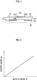
- a radiated microwave amount Sir and an absorbed microwave amount Sab are in a proportional relationship as illustrated in FIG. 5 . Accordingly, even when the radiated microwave amount Sir is changed under a condition that the temperature of the exhaust catalyst 52 is constant, the ratio Sab/Sir of the absorbed microwave amount Sab to the radiated microwave amount Sir, that is, the microwave absorbance, is constant. That is, the temperature of the exhaust catalyst 52 is changed when the microwave absorbance Sab/Sir is changed.
- a microwave reflectance Rre that is the ratio of the reflected microwave to the microwave radiated from the antenna A1 is acquired by General Formula (2).
- a microwave absorbance Rab is acquired by General Formula (3).
- Microwave reflectance Rre Sre / Sir
- Microwave absorbance Rab Sir ⁇ Sre / Sir
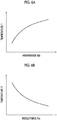
- the microwave absorbance Rab of the exhaust catalyst 52 is increased. Accordingly, a relationship in which the temperature of the exhaust catalyst 52 is increased as the microwave absorbance Rab is increased is established as illustrated in FIG. 6A . Thus, the temperature of the exhaust catalyst 52 can be estimated from the microwave absorbance Rab. As described above, the microwave absorbance Rab is one of "temperature-correlated values" that are values correlated with the temperature of the exhaust catalyst 52.
- the temperature of the exhaust catalyst 52 is decreased as the microwave reflectance Rre is increased is established as illustrated in FIG. 6B .
- the temperature of the exhaust catalyst 52 can be estimated from the microwave reflectance Rre.
- the microwave reflectance Rre is one of "temperature-correlated values" that are values correlated with the temperature of the exhaust catalyst 52.
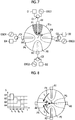
- the four antennas 61a, 61b, 61c, 61d are respectively denoted by reference signs A1, A3, A2, A4 for convenience.
- the four microwave generators 63a, 63b, 63c, 63d are respectively denoted by reference signs OSC1, OSC3, OSC2, OSC4 for convenience.
- the four microwave detectors 64a, 64b, 64c, 64d are respectively denoted by reference signs D1, D3, D2, D4 for convenience.
- the four circulators 65a, 65b, 65c, 65d are respectively denoted by reference signs C1, C3, C2, C4 for convenience.
- the microwave generators OSC1 to OSC4 and the microwave detectors D1 to D4 are respectively connected to the antennas A1 to A4 through the circulators C1 to C4.
- the microwave generator OSC1, the microwave detector D1, and the circulator C1 are included in one microwave transmission and reception device 62a.
- the antenna A1, the antenna A2, the antenna A3, and the antenna A4 are disposed close to the first part P1 of the exhaust catalyst 52, the second part P2 of the exhaust catalyst 52, a third part P3 of the exhaust catalyst 52, and a fourth part P4 of the exhaust catalyst 52 respectively.
- the antennas A1 to A4 are disposed toward a center C0 of the exhaust catalyst 52 from the outer circumferential surface 51c.
- the distance between the tip ends of the opposing antennas An is 100 mm.
- a method of estimating the temperature of parts of the exhaust catalyst 52 (the first part P1, the second part P2, and the like) close to each antenna 61 using the first heating device that is, a method of acquiring the temperature-correlated value for the parts close to each antenna 61, will be more specifically described using the principle.
- the temperature of the first part P1 will be illustratively described as being lower than the temperature of the other parts.
- the first heating device executes a "first radiation control" for radiating the microwave from merely the antenna A1.
- a “first radiation control” for radiating the microwave from merely the antenna A1.
- configuring the antennas A2, A3, A4 not radiating the microwave to exhibit total internal reflection can suppress leakage of the electromagnetic wave to the antennas A2, A3, A4 from the antenna A1.
- the onward specific radiation control since the temperature of the first part P1 is lower than the temperature of the other parts, the microwave absorbance in the first part P1 is lower than the microwave absorbance in the other parts (the second part P2 to the fourth part P4).
- the CPU acquires the intensity of the microwave incident on the antenna A1 as a "first electromagnetic wave intensity" using the microwave detector D1. Since the microwave absorbance in the first part P1 is lower than the microwave absorbance in the other parts, the value of the "first electromagnetic wave intensity" is comparatively high.
- the CPU Based on the first electromagnetic wave intensity, the CPU acquires a "first temperature-correlated value" that is a value correlated with the temperature of the first part P1. In such a case, the CPU acquires the microwave absorbance as the first temperature-correlated value based on General Formula (2).
- the CPU may acquire the temperature of the first part P1 using the correlation map (lookup table) illustrated in FIG. 6A .
- the CPU executes a "second radiation control" for radiating the microwave from merely the antenna A2 as the "specific radiation control".
- the microwave absorbance in the second part P2 is higher than the microwave absorbance in the first part P1 and is approximately the same as (average value of) the microwave absorbance in the third part P3 and the fourth part P4.
- the CPU acquires the intensity of the microwave incident on the antenna A2 as a "second electromagnetic wave intensity" using the microwave detector D2. Since the microwave absorbance in the second part P2 is higher than the microwave absorbance in the first part P1 and is approximately the same as (average value of) the microwave absorbance in the third part P3 and the fourth part P4, the value of the "second electromagnetic wave intensity" is lower than (approximately half of) the "first electromagnetic wave intensity”.
- the CPU Based on the second electromagnetic wave intensity, the CPU acquires a "second temperature-correlated value" that is a value correlated with the temperature of the second part P2. In such a case, the CPU acquires the microwave absorbance as the second temperature-correlated value based on General Formula (2).
- the CPU may acquire the temperature of the second part P2 using the correlation map illustrated in FIG. 6A .
- the CPU executes a "third radiation control" for radiating the microwave from merely the antenna A3 as the "specific radiation control".
- the microwave absorbance in the third part P3 is higher than the microwave absorbance in the first part P1 and is approximately the same as (average value of) the microwave absorbance in the second part P2 and the fourth part P4.
- the CPU acquires the intensity of the microwave incident on the antenna A3 as a "third electromagnetic wave intensity" using the microwave detector D3. Since the microwave absorbance in the third part P3 is higher than the microwave absorbance in the first part P1 and is approximately the same as (average value of) the microwave absorbance in the second part P2 and the fourth part P4, the "third electromagnetic wave intensity" has approximately the same value as the "second electromagnetic wave intensity".
- the CPU Based on the third electromagnetic wave intensity, the CPU acquires a "third temperature-correlated value" that is a value correlated with the temperature of the third part P3. In such a case, the CPU acquires the microwave absorbance as the third temperature-correlated value based on General Formula (2).
- the CPU may acquire the temperature of the third part P3 using the correlation map illustrated in FIG. 6A .
- the CPU executes a "fourth radiation control" for radiating the microwave from merely the antenna A4 as the "specific radiation control".
- the microwave absorbance in the fourth part P4 is higher than the microwave absorbance in the first part P1 and is approximately the same as (average value of) the microwave absorbance in the second part P2 and the third part P3.
- the CPU acquires the intensity of the microwave incident on the antenna A4 as a "fourth electromagnetic wave intensity" using the microwave detector D4. Since the microwave absorbance in the fourth part P4 is higher than the microwave absorbance in the first part P1 and is approximately the same as (average value of) the microwave absorbance in the second part P2 and the third part P3, the "fourth electromagnetic wave intensity" has approximately the same value as the "second electromagnetic wave intensity” and the "third electromagnetic wave intensity”.
- the CPU Based on the fourth electromagnetic wave intensity, the CPU acquires a "fourth temperature-correlated value" that is a value correlated with the temperature of the fourth part P4. In such a case, the CPU acquires the microwave absorbance as the fourth temperature-correlated value based on General Formula (2).
- the CPU may acquire the temperature of the fourth part P4 using the correlation map illustrated in FIG. 6A .
- the intensity of the reflective wave when the first radiation control (a control for radiating the microwave from merely the antenna A1) is executed, the value of the first electromagnetic wave intensity is comparatively high as illustrated in Table 1.
- the values of the second electromagnetic wave intensity, the third electromagnetic wave intensity, and the fourth electromagnetic wave intensity are approximately moderate.
- the result of summarization of the intensity of the reflective wave when the temperature of the first part P1, among the first part P1 to the fourth part P4 respectively close to the four antennas A1 to A4, is higher than the temperature of the other parts is illustrated in Table 2.
- the first radiation control a control for radiating the microwave from merely the antenna A1
- the value of the first electromagnetic wave intensity is comparatively low.
- the other radiation controls are executed, the values of the second electromagnetic wave intensity, the third electromagnetic wave intensity, and the fourth electromagnetic wave intensity are approximately moderate.
- a microwave having a first predetermined intensity is radiated from the antenna A1 in a period t 1 .
- a microwave having a second predetermined intensity is radiated from the antenna A2 in a period t 2 .
- a microwave having a third predetermined intensity is radiated from the antenna A3 in a period t 3 .
- a microwave having a fourth predetermined intensity is radiated from the antenna A4 in a period t 4 .
- the first predetermined intensity to the fourth predetermined intensity are the same as each other.
- each radiation time period (radiation period) is 1 msec. Accordingly, microwaves from different antennas are incident in order on the antenna A4 per predetermined period.
- the first heating device can specify each antenna from which each microwave is radiated, by associating the order of the radiated microwaves with the positions of the antennas.
- the CPU of the ECU 100 executes a catalyst temperature distribution estimation routine illustrated by a flowchart in FIG. 9 for each elapse of a predetermined time period. Accordingly, when a predetermined timing is reached, the CPU starts processing from step 900 in FIG. 9 and transitions to step 905 to determine whether or not the value of a catalyst temperature distribution estimation execution flag Xest is equal to "1".
- the value of the catalyst temperature distribution estimation execution flag Xest is set to "1" in a routine that is separately executed.
- the catalyst temperature distribution estimation execution flag Xest is set to "1" when an ignition switch or a start switch not illustrated is switched to an ON state from an OFF state.
- the catalyst temperature distribution estimation execution flag Xest is set to "1" per few seconds while the CPU is executing a catalyst temperature increasing control for increasing the temperature of the catalyst 52 by heating. Accordingly, the catalyst temperature distribution can be monitored very frequently during the catalyst temperature increasing control so that the temperature of the catalyst 52 is not excessively increased.
- the catalyst temperature distribution estimation execution flag Xest is set to "1" a few times per one minute.
- the catalyst temperature distribution estimation execution flag Xest is set to "1" at time intervals set in advance (for example, every five minutes).
- step 905 When the catalyst temperature distribution estimation execution flag Xest is set to "1", the CPU makes a "Yes" determination in step 905 and processes step 910 to step 950 described below in order. Then, the CPU transitions to step 995 to temporarily finish the present routine.
- step 905 When the catalyst temperature distribution estimation execution flag Xest is equal to "0", and the CPU makes a "No" determination in step 905, the CPU directly transitions to step 995 to temporarily finish the present routine.
- the CPU executes, as the specific radiation control, the first radiation control for controlling the operation of the microwave generators OSC1 to OSC4 to set a radiation state where the electromagnetic wave is radiated to the first part P1 from the first antenna A1, and where electromagnetic waves are not radiated to the second part P2, the third part P3, and the fourth part P4 respectively from the second antenna A2, the third antenna A3, and the fourth antenna A4.
- the CPU acquires, as the first electromagnetic wave intensity, the intensity of the electromagnetic wave that is incident on the first antenna A1 at the execution of the first radiation control.
- the CPU executes, as the specific radiation control, the second radiation control for controlling the operation of the microwave generators OSC1 to OSC4 to set a radiation state where the electromagnetic wave is radiated to the second part P2 from the second antenna A2, and where electromagnetic waves are not radiated to the first part P1, the third part P3, and the fourth part P4 respectively from the first antenna A1, the third antenna A3, and the fourth antenna A4.
- the CPU acquires, as the second electromagnetic wave intensity, the intensity of the electromagnetic wave that is incident on the second antenna A2 at the execution of the second radiation control.
- the CPU executes, as the specific radiation control, the third radiation control for controlling the operation of the microwave generators OSC1 to OSC4 to set a radiation state where the electromagnetic wave is radiated to the third part P3 from the third antenna A3, and where electromagnetic waves are not radiated to the first part P1, the second part P2, and the fourth part P4 respectively from the first antenna A1, the second antenna A2, and the fourth antenna A4.
- the CPU acquires, as the third electromagnetic wave intensity, the intensity of the electromagnetic wave that is incident on the third antenna A3 at the execution of the third radiation control.
- the CPU executes, as the specific radiation control, the fourth radiation control for controlling the operation of the microwave generators OSC1 to OSC4 to set a radiation state where the electromagnetic wave is radiated to the fourth part P4 from the fourth antenna A4, and where electromagnetic waves are not radiated to the first part P1, the second part P2, and the third part P3 respectively from the first antenna A1, the second antenna A2, and the third antenna A3.
- the CPU acquires, as the fourth electromagnetic wave intensity, the intensity of the electromagnetic wave that is incident on the fourth antenna A4 at the execution of the fourth radiation control.
- the first heating device can acquire the intensity of the electromagnetic wave radiated from each antenna without being affected by the electromagnetic wave from the other antennas.
- the first heating device can accurately acquire the temperature of a specific part (temperature-correlated value) of the catalyst 52 and estimate the temperature distribution of the catalyst 52.
- the first heating device executes the temperature increasing control of the exhaust catalyst 52 using the following method.
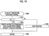
- the CPU of the ECU 100 executes a catalyst temperature increasing control routine illustrated by a flowchart in FIG. 10 for each elapse of a predetermined time period. Accordingly, when a predetermined timing is reached, the CPU starts processing from step 1000 in FIG. 10 and transitions to step 1010 to determine whether or not the value of a catalyst temperature increasing flag Xss is equal to "1".
- the value of the catalyst temperature increasing flag Xss is changed to "1" from "0" when any of the following two conditions is established.
- a first condition is that the ignition switch or the start switch not illustrated is switched to the ON state from the OFF state.
- a predetermined temperature range (predetermined range) for normal functioning of the exhaust catalyst 52 is set for the exhaust catalyst 52.
- the lower limit of the temperature range is regulated with a temperature (activation temperature) at which the exhaust catalyst 52 can sufficiently exhibit a capability to control the exhaust gas.
- the upper limit of the temperature range is regulated with a temperature that is acquired by considering the risk of loss of the exhaust catalyst 52 by melting.
- a second condition is that a temperature-correlated value CVn becomes equal to the temperature-correlated value CVn that corresponds to a case where the temperature of the exhaust catalyst 52 (hereinafter, referred to as "catalyst temperature”) is lower than the predetermined temperature range (lower than the temperature lower limit).
- the first heating device performs the determination based on an average value CVavg of a first temperature-correlated value CV1, a second temperature-correlated value CV2, a third temperature-correlated value CV3, and a fourth temperature-correlated value CV4.
- the CPU makes a "Yes” determination in step 1010 and transitions to step 1020 to cause each antenna to radiate an electromagnetic wave having a predetermined intensity for increasing the temperature of the catalyst. Then, the CPU transitions to step 1095 to temporarily finish the present routine.
- the value of the catalyst temperature increasing flag Xss is changed to "0" from "1" when any of the following two conditions is established.
- a first condition is that the ignition switch or the start switch is switched to the OFF state from the ON state.
- a second condition is that the temperature-correlated value CVn (average value CVavg) becomes equal to the temperature-correlated value CVn (average value CVavg) that corresponds to a case where the catalyst temperature is higher than the predetermined temperature range (exceeds the temperature upper limit).
- the CPU makes a "No” determination in step 1010 and transitions to step 1030 to stop radiation of the electromagnetic wave. Then, the CPU transitions to step 1095 to temporarily finish the present routine.
- the heating device may be configured to individually perform the determination for each temperature-correlated value CVn and individually control the intensity of the microwave radiated from each antenna.
- the first heating device can acquire each temperature-correlated value for each part (the first part P1 to the fourth part P4) and then, can perform a control for reducing variation according to the magnitude of variation (deviation) in the catalyst temperature. For example, it is assumed that the first heating device is in a state of executing the catalyst temperature increasing control for radiating the microwave from each antenna.
- each temperature-correlated value is (1) a correlated value that is increased along with an increase in temperature (for example, the microwave absorbance), and the difference between each temperature-correlated value CVn (n is 1, 2, 3, and 4) and the average value CVavg of the temperature correlated values has a positive value (CVn - CVavg > 0)
- the first heating device determines that the temperature of the "n-th part Pn" corresponding to each temperature-correlated value is high. In such a case, the first heating device decreases the intensity of the microwave radiated from the n-th antenna An by a predetermined amount in order to decrease the temperature of the n-th part Pn.
- the first heating device may stop radiation of the microwave.
- the first heating device determines that the temperature of the "n-th part Pn" corresponding to each temperature-correlated value is low. In such a case, the first heating device increases the intensity of the microwave radiated from the n-th antenna An by a predetermined amount in order to increase the temperature of the n-th part Pn.
- each temperature-correlated value is (2) a correlated value that is decreased along with an increase in temperature (for example, the microwave reflectance), and the difference between each temperature-correlated value CVn and the average value CVavg of the temperature correlated values has a negative value (CVn - CVavg ⁇ 0)
- the first heating device determines that the temperature of the "n-th part Pn" corresponding to each temperature-correlated value is high. In such a case, the first heating device decreases the intensity of the microwave radiated from the n-th antenna An by a predetermined amount in order to decrease the temperature of the n-th part Pn.
- the first heating device may stop radiation of the microwave.
- the first heating device determines that the temperature of the "n-th part Pn" corresponding to each temperature-correlated value is low. In such a case, the first heating device increases the intensity of the microwave radiated from the n-th antenna An by a predetermined amount in order to increase the temperature of the n-th part Pn.
- the first heating device can approximate each temperature-correlated value to the average value CVavg. Accordingly, the deviation in the temperature-correlated value of each part, that is, the deviation in the temperature of each n-th part Pn can be decreased, and the risk of damage such as a crack caused by a difference in the temperature of the exhaust catalyst 52 can be reduced.
- the predetermined temperature range for normal functioning of the catalyst 52 is set for the catalyst 52.
- each temperature-correlated value is (1) a correlated value that is increased along with an increase in temperature (for example, the microwave absorbance)
- the first heating device defines CVmin as the lower limit of each temperature-correlated value corresponding to the lower limit of the predetermined temperature range, and defines CVmax as the upper limit of each temperature-correlated value corresponding to the upper limit of the predetermined temperature range.
- CVmin the lower limit of each temperature-correlated value corresponding to the lower limit of the predetermined temperature range
- CVmax the upper limit of each temperature-correlated value corresponding to the upper limit of the predetermined temperature range.
- the first heating device determines that the temperature of the n-th part Pn corresponding to each temperature-correlated value exceeds the upper limit. In such a case, the first heating device decreases the intensity of the microwave radiated from the antenna An by a predetermined amount in order to decrease the temperature of the n-th part Pn.
- the first heating device may stop radiation of the microwave.
- the first heating device determines that the temperature of the n-th part Pn corresponding to each temperature-correlated value is lower than the lower limit. In such a case, the first heating device increases the intensity of the microwave radiated from the antenna An by a predetermined amount in order to increase the temperature of the n-th part Pn.
- the first heating device defines CVmax as the upper limit of each temperature-correlated value corresponding to the lower limit of the predetermined temperature range, and defines CVmin as the lower limit of each temperature-correlated value corresponding to the upper limit of the predetermined temperature range.
- CVn is lower than the lower limit CVmin of the temperature-correlated value
- the first heating device determines that the temperature of the n-th part Pn corresponding to each temperature-correlated value exceeds the upper limit. In such a case, the first heating device decreases the intensity of the microwave radiated from the antenna An by a predetermined amount in order to decrease the temperature of the n-th part Pn.
- the first heating device may stop radiation of the microwave.
- the first heating device determines that the temperature of the n-th part Pn corresponding to each temperature-correlated value is lower than the lower limit. In such a case, the first heating device increases the intensity of the microwave radiated from the antenna An by a predetermined amount in order to increase the temperature of the n-th part Pn.
- each temperature-correlated value is a correlated value that is increased along with an increase in temperature.
- the CPU of the ECU 100 executes a catalyst temperature variation correction routine illustrated by a flowchart in FIG. 11 for each elapse of a predetermined time period. Accordingly, when a predetermined timing is reached, the CPU starts processing from step 1100 in FIG. 11 and transitions to step 1105 to execute the catalyst temperature distribution estimation (temperature-correlated value acquisition) routine. That is, the CPU transitions to step 900 to execute the catalyst temperature distribution estimation routine, and acquires each temperature-correlated value CVn. When the catalyst temperature distribution estimation routine is temporarily finished, the CPU transitions to step 1110.
- step 1110 the CPU acquires the average value CVavg of each temperature-correlated value based on General Formula (4). Then, the CPU transitions to step 1115 to determine whether or not the first temperature-correlated value CV1 is higher than the upper limit CVmax of each temperature-correlated value. When the first temperature-correlated value CV1 is higher than the upper limit CVmax of each temperature-correlated value, the CPU makes a "Yes" determination in step 1115 and transitions to step 1120 to determine whether or not the CPU is separately executing the "catalyst temperature increasing control".
- step 1120 When the CPU is executing the catalyst temperature increasing control, the CPU makes a "Yes” determination in step 1120 and transitions to step 1125 to stop the antenna A1 from radiating the electromagnetic wave. Then, the CPU transitions to step 1170.
- the CPU When the CPU is not executing the catalyst temperature increasing control, the CPU makes a "No" determination in step 1120 and directly transitions to step 1170.
- the CPU makes a "No" determination in step 1115 and transitions to step 1130 to determine whether or not the first temperature-correlated value CV1 is lower than the lower limit CVmin of each temperature-correlated value.
- the CPU makes a "Yes” determination in step 1130 and transitions to step 1135 to increase the intensity of the electromagnetic wave of the antenna A1 by a predetermined amount. Then, the CPU transitions to step 1170.
- the CPU makes a "No" determination in step 1130 and transitions to step 1140. The CPU determines whether or not the first temperature-correlated value CV1 is higher than the average value CVavg of each temperature-correlated value CVn.
- the CPU makes a "Yes” determination in step 1140 and transitions to step 1145 to determine whether or not the CPU is executing the catalyst temperature increasing control.
- the CPU makes a "Yes” determination in step 1145 and transitions to step 1150 to decrease the intensity of the electromagnetic wave of the antenna A1 by a predetermined amount. Then, the CPU transitions to step 1170.
- the CPU makes a "No" determination in step 1145 and directly transitions to step 1170.
- the CPU makes a "No" determination in step 1140 and transitions to step 1155 to determine whether or not the first temperature-correlated value CV1 is lower than the average value CVavg of each temperature-correlated value CVn.
- the CPU makes a "Yes" determination in step 1155 and transitions to step 1160 to increase the intensity of the electromagnetic wave of the antenna A1 by a predetermined amount. Then, the CPU transitions to step 1170.
- the CPU makes a "No" determination in step 1155 and transitions to step 1165. In such a case, the CPU maintains the intensity of the electromagnetic wave of the antenna A1 and transitions to step 1170.
- step 1170 the CPU executes the same control for the second temperature-correlated value CV2 as the control executed for the first temperature-correlated value CV1 in step 1115 to step 1165.
- step 1175 and step 1180 the CPU executes the same control for the third temperature-correlated value CV3 and the fourth temperature-correlated value CV4 as the control executed for the second temperature-correlated value CV2 in step 1170. Then, the CPU transitions to step 1195 to temporarily finish the present routine.
- the first heating device is configured to control the operation of the electromagnetic wave generator to adjust the intensity of the electromagnetic wave radiated from the n-th antenna such that the n-th temperature-correlated value becomes a value that falls within the predetermined range.
- a heating device for an exhaust catalyst according to a second embodiment of the present invention (hereinafter, referred to as "second heating device") will be described.
- the second heating device has a different method of acquiring the temperature-correlated value from the first heating device. Accordingly, hereinafter, the method of acquiring the temperature-correlated value using the second heating device will be described.
- Microwaves having different oscillation frequencies (oscillation frequencies f1, f2, f3, f4) and a predetermined intensity (same intensity) are radiated at the same time from each antenna An.
- the oscillation frequencies f1 to f4 of the microwave generators OSC1 to OSC4 are set to 2.420 GHz, 2.450 GHz, 2.480 GHz, and 2.510 GHz (30 MHz interval) respectively.
- the oscillation frequencies f1 to f4 will be referred to as the first frequency f1 to the fourth frequency f4 respectively.
- the frequencies are for illustrative purposes and are not intended to limit the present invention.
- Reflective waves that are input into each antenna An are separated from each other by each of the microwave detectors D1 to D4 according to the frequency.
- the separation of the reflective waves according to the frequency uses a bandpass filter that corresponds to each frequency band.
- the intensity of the microwave for each reflective wave separated according to the frequency is measured by each of the microwave detectors D1 to D4.
- the temperature of the part of the catalyst 52 close to the antenna An corresponding to the intensity of each reflective wave at each frequency is estimated to be low.
- the microwave having the oscillation frequency f1 from the antenna A1, the microwave having the oscillation frequency f2 from the antenna A2, the microwave having the oscillation frequency f3 from the antenna A3, and the microwave having the oscillation frequency f4 from the antenna A4 are radiated to the antenna A4. Accordingly, microwaves from different antennas are incident on the antenna A4 at the same time.
- the second heating device can specify each antenna from which each microwave is radiated, by associating the oscillation frequencies of the radiated microwaves with the positions of the antennas.
- the CPU of the ECU 100 executes a catalyst temperature distribution estimation routine illustrated by a flowchart in FIG. 14 for each elapse of a predetermined time period. Accordingly, when a predetermined timing is reached, the CPU starts processing from step 1400 in FIG. 14 and transitions to step 1410 to determine whether or not the value of the catalyst temperature distribution estimation execution flag Xest is equal to "1".
- step 1410 When the value of the catalyst temperature distribution estimation execution flag Xest is equal to "1", the CPU makes a "Yes” determination in step 1410 and processes step 1420 to step 1450 described below in order. Then, the CPU transitions to step 1495 to temporarily finish the present routine.
- step 1410 When the value of the catalyst temperature distribution estimation execution flag Xest is equal to "0", and the CPU makes a "No" determination in step 1410, the CPU directly transitions to step 1495 to temporarily finish the present routine.
- the CPU controls, as the specific radiation control, the operation of the microwave generators OSC1 to OSC4 to set a radiation state where the electromagnetic wave from the first antenna A1 oscillates at the first frequency f1, a radiation state where the electromagnetic wave from the second antenna A2 oscillates at the second frequency f2 different from the first frequency f1, a radiation state where the electromagnetic wave from the third antenna A3 oscillates at the third frequency f3 different from the first frequency f1 and the second frequency f2, and a radiation state where the electromagnetic wave from the fourth antenna A4 oscillates at the fourth frequency f4 different from the first frequency f1, the second frequency f2, and the third frequency f3.
- the second heating device can acquire the intensity of the electromagnetic wave radiated by each antenna without being affected by the electromagnetic wave radiated from the other antennas.
- the second heating device can accurately acquire the temperature of a specific part (temperature-correlated value) of the catalyst 52 and estimate the temperature distribution of the catalyst 52.
- each temperature-correlated value is corrected by changing the intensity of the microwave radiated from each antenna when variation in catalyst temperature is corrected
- each temperature-correlated value may be corrected by changing the oscillation frequency of the microwave.
- the heating device may correct each temperature-correlated value by changing the duty cycle of the pulse width instead of changing the intensity of the microwave.
- the heating device may correct each temperature-correlated value by changing the phase of the microwave radiated from each antenna.
- the CPU of the ECU 100 executes a catalyst temperature variation correction routine illustrated by a flowchart in FIG. 15 for each elapse of a predetermined time period. Accordingly, when a predetermined timing is reached, the CPU starts processing from step 1500 in FIG. 15 and transitions to step 1510 to execute the catalyst temperature distribution estimation (temperature-correlated value acquisition) routine. That is, the CPU transitions to step 900 to execute the catalyst temperature distribution estimation routine, and acquires each temperature-correlated value CVn. When the catalyst temperature distribution estimation routine is temporarily finished, the CPU transitions to step 1520.
- the CPU acquires an engine load KL based on the opening degree of the throttle valve acquired by a throttle valve opening degree sensor not illustrated.
- the CPU transitions to step 1530 and acquires the oscillation frequency of the microwave radiated from each antenna by applying the acquired engine load KL and the acquired temperature-correlated value CV to a lookup table (refer to FIG. 16 ) that is stored in the ROM and defines a relationship among "the engine load KL, the temperature-correlated value CV, and the oscillation frequency f of the microwave".
- the CPU transitions to step 1540 and performs radiation by changing the oscillation frequency f of the microwave radiated from each antenna to the oscillation frequency acquired in step 1530. Then, the CPU transitions to step 1595 to temporarily finish the present routine.
- Each temperature-correlated value may be corrected by changing the output duty cycle of the microwave.
- an output duty cycle DR of the microwave is acquired by applying the acquired engine load KL and the acquired temperature-correlated value CV to a lookup table that is stored in the ROM and defines a relationship among "the engine load KL, the temperature-correlated value CV, and the output duty cycle DR of the microwave".
- Each temperature-correlated value may be corrected by changing a phase Ph of the microwave.
- the phase Ph of the microwave is acquired by applying the acquired engine load KL and the acquired temperature-correlated value CV to a lookup table that is stored in the ROM and defines a relationship among "the engine load KL, the temperature-correlated value CV, and the phase Ph of the microwave".
- An intensity S of the microwave may also be acquired by applying the acquired engine load KL and the acquired temperature-correlated value CV to a preset lookup table that is stored in the ROM and defines a relationship among "the engine load KL, the temperature-correlated value CV, and the intensity S of the microwave".
- the relationship defined in the lookup table may have the catalyst temperature instead of the temperature-correlated value CV.
- a step of acquiring the catalyst temperature from the temperature-correlated value CV may be added to the flowchart illustrated in FIG. 15 .
- the heating device for an exhaust catalyst is configured to control the operation of the electromagnetic wave generator to adjust at least one of the intensity and the output duty cycle of the electromagnetic wave radiated from the n-th antenna such that the n-th temperature-correlated value becomes a value that falls within the predetermined range.
- the heating device 60 may include at least the first antenna A1 that is disposed close to the first part P1 of the catalyst 52 and radiates the electromagnetic wave generated by the microwave generator OSC1 to the first part P1, and the second antenna A2 that is disposed close to the second part P2 different from the first part P1 and radiates the electromagnetic wave generated by the microwave generator OSC2 to the second part P2. That is, the heating device 60 may include at least two antennas.
- the CPU when the temperature-correlated value acquisition control that is performed with different radiation timings for radiating the microwave from each antenna is executed, the CPU performs the first radiation control to the fourth radiation control in the order of the first antenna A1, the second antenna A2, the third antenna A3, and the fourth antenna A4.
- the radiation order for the first radiation control to the fourth radiation control is not particularly limited. While the time period of executing each of the first radiation control to the fourth radiation control is the same, the length of the time period does not need to be the same and may be appropriately adjusted within a range where the time period in which the microwave detector 64 can perform detection can be secured.
- the magnitude relationship between the oscillation frequencies of the microwave radiated from each antenna is set to be a relationship of first frequency f1 ⁇ second frequency f2 ⁇ third frequency f3 ⁇ fourth frequency f4.
- the magnitude relationship is not particularly limited. While the intervals between each oscillation frequency are equal to each other, the intervals do not need to be equal to each other and may be appropriately adjusted within a range where the oscillation frequencies can be separated by the bandpass filter.
- the microwave transmitted to the antenna 61 from the microwave generator 63 and the microwave transmitted to the microwave detector 64 from the antenna 61 are separated from each other by the circulator 65.
- a radiation antenna that is connected to merely the microwave generator 63, and an incidence antenna that is adjacent to the radiation antenna and is connected to merely the microwave detector 64 may be included.
- a microwave absorbing member may be disposed in order to suppress direct incidence of the microwave from the adjacent radiation antenna on the incidence antenna.
- the exhaust catalyst may be applied to a diesel engine catalyst, a DPF (diesel particulate filter), and the like.
Landscapes
- Chemical & Material Sciences (AREA)
- Engineering & Computer Science (AREA)
- Chemical Kinetics & Catalysis (AREA)
- Physics & Mathematics (AREA)
- Electromagnetism (AREA)
- Toxicology (AREA)
- Mechanical Engineering (AREA)
- General Engineering & Computer Science (AREA)
- Combustion & Propulsion (AREA)
- Health & Medical Sciences (AREA)
- Ceramic Engineering (AREA)
- Power Engineering (AREA)
- Exhaust Gas After Treatment (AREA)
- Processes For Solid Components From Exhaust (AREA)
- Exhaust Gas Treatment By Means Of Catalyst (AREA)
Claims (4)
- Dispositif de chauffage destiné à un catalyseur (52) d'échappement disposé dans un passage d'échappement d'un moteur à combustion interne, le catalyseur (52) d'échappement étant configuré pour générer de la chaleur en absorbant une onde électromagnétique, le dispositif de chauffage comprenant au moins un générateur (63) d'ondes électromagnétiques configuré pour générer une onde électromagnétique et une première antenne (61a) disposée, en cours d'utilisation, près d'une première partie du catalyseur (52) d'échappement et un dispositif (100) de commande électronique, la première antenne (61a) étant configurée pour rayonner une onde électromagnétique générée par le générateur (63) d'ondes électromagnétiques vers la première partie, le dispositif de chauffage étant caractérisé en ce qu'il comporte :une seconde antenne (61c) disposée, en cours d'utilisation, près d'une seconde partie du catalyseur (52) d'échappement différente de la première partie, la seconde antenne (61c) étant disposée à un intervalle prédéterminé de la première antenne (61a), la seconde antenne (61c) étant configurée pour rayonner une onde électromagnétique générée par le générateur (63) d'ondes électromagnétiques vers la seconde partie ;le dispositif (100) de commande électronique étant configuré pourexécuter une commande d'augmentation de température du catalyseur servant à augmenter la température du catalyseur (52) d'échappement en commandant le générateur (63) d'ondes électromagnétiques pour rayonner l'onde électromagnétique vers la première partie et la seconde partie respectivement à partir de la première antenne (61a) et de la seconde antenne (61c),exécuter une commande de rayonnement spécifique servant à commander le fonctionnement du générateur (63) d'ondes électromagnétiques afin d'établir un état de rayonnement de l'onde électromagnétique provenant de la première antenne (61a) pour qu'il soit un état différent d'un état de rayonnement de l'onde électromagnétique provenant de la seconde antenne (61c), acquérir l'intensité d'une onde électromagnétique, parmi des ondes électromagnétiques incidentes sur la première antenne (61a) lors de l'exécution de la commande de rayonnement spécifique, qui correspond à l'état de rayonnement de l'onde électromagnétique rayonnée à partir de la première antenne (61a) en tant que première intensité d'onde électromagnétique,acquérir l'intensité d'une onde électromagnétique, parmi des ondes électromagnétiques incidentes sur la seconde antenne (61c) lors de l'exécution de la commande de rayonnement spécifique, qui correspond à l'état de rayonnement de l'onde électromagnétique rayonnée à partir de la seconde antenne (61c) en tant que seconde intensité d'onde électromagnétique, acquérir, d'après la première intensité d'onde électromagnétique, une première valeur corrélée à la température qui est une valeur corrélée avec la température de la première partie,acquérir, d'après la seconde intensité d'onde électromagnétique, une seconde valeur corrélée à la température qui est une valeur corrélée avec la température de la seconde partie, etlorsque la première valeur corrélée à la température et la seconde valeur corrélée à la température sont différentes l'une de l'autre, commander le fonctionnement du générateur (63) d'ondes électromagnétiques pour régler au moins un paramètre parmi l'intensité et le cycle de marche en sortie de l'onde électromagnétique rayonnée à partir d'au moins une antenne parmi la première antenne (61a) et la seconde antenne (61c) de telle façon que l'écart entre la première valeur corrélée à la température et la seconde valeur corrélée à la température soit diminué dans la commande d'augmentation de température du catalyseur.
- Dispositif de chauffage selon la revendication 1 :le dispositif (100) de commande électronique étant configuré pour exécuter, en tant que commande de rayonnement spécifique, une première commande de rayonnement visant à commander le fonctionnement du générateur (63) d'ondes électromagnétiques afin d'établir l'état de rayonnement pour qu'il soit un état où une onde électromagnétique est rayonnée vers la première partie en provenance de la première antenne (61a), et où une onde électromagnétique n'est pas rayonnée vers la seconde partie en provenance de la seconde antenne (61c), et une seconde commande de rayonnement visant à commander le fonctionnement du générateur (63) d'ondes électromagnétiques afin d'établir l'état de rayonnement pour qu'il soit un état où une onde électromagnétique n'est pas rayonnée vers la première partie en provenance de la première antenne (61a), et où une onde électromagnétique est rayonnée vers la seconde partie en provenance de la seconde antenne (61c) ;le dispositif de commande électronique étant configuré pour acquérir, en tant que première intensité d'onde électromagnétique, l'intensité des ondes électromagnétiques incidentes sur la première antenne (61a) lors de l'exécution de la première commande de rayonnement ; etle dispositif (100) de commande électronique étant configuré pour acquérir, en tant que seconde intensité d'onde électromagnétique, l'intensité des ondes électromagnétiques incidentes sur la seconde antenne (61c) lors de l'exécution de la seconde commande de rayonnement.
- Dispositif de chauffage selon la revendication 1 :le dispositif (100) de commande électronique étant configuré, au titre de la commande de rayonnement spécifique, pour commander le fonctionnement du générateur (63) d'ondes électromagnétiques de façon à rayonner une onde électromagnétique présentant une première fréquence à partir de la première antenne (61a) et rayonner une onde électromagnétique présentant une seconde fréquence différente de la première fréquence à partir de la seconde antenne (61c) ; etle dispositif (100) de commande électronique étant configuré pour acquérir, en tant que première intensité d'onde électromagnétique, l'intensité de l'onde électromagnétique présentant la première fréquence parmi les ondes électromagnétiques incidentes sur la première antenne (61a) lors de l'exécution de la commande de rayonnement spécifique, et acquérir, en tant que seconde intensité d'onde électromagnétique, l'intensité de l'onde électromagnétique présentant la seconde fréquence parmi les ondes électromagnétiques incidentes sur la seconde antenne (61c) lors de l'exécution de la commande de rayonnement spécifique.
- Dispositif de chauffage selon l'une quelconque des revendications 1 à 3 :le dispositif (100) de commande électronique étant configuré, lorsque la première valeur corrélée à la température n'est pas une valeur qui se situe à l'intérieur d'une plage prédéterminée, pour commander le fonctionnement du générateur (63) d'ondes électromagnétiques afin de régler au moins un paramètre parmi l'intensité et un cycle de marche en sortie de l'onde électromagnétique rayonnée à partir de la première antenne (61a) de telle façon que la première valeur corrélée à la température devienne une valeur qui se situe à l'intérieur de la plage prédéterminée ; etle dispositif (100) de commande électronique étant configuré, lorsque la seconde valeur corrélée à la température n'est pas une valeur qui se situe à l'intérieur de la plage prédéterminée, pour commander le fonctionnement du générateur (63) d'ondes électromagnétiques afin de régler au moins un paramètre parmi l'intensité et un cycle de marche en sortie de l'onde électromagnétique rayonnée à partir de la seconde antenne (61c) de telle façon que la seconde valeur corrélée à la température devienne une valeur qui se situe à l'intérieur de la plage prédéterminée.
Applications Claiming Priority (2)
| Application Number | Priority Date | Filing Date | Title |
|---|---|---|---|
| JP2017063085A JP6669116B2 (ja) | 2017-03-28 | 2017-03-28 | 排気浄化触媒の加熱装置 |
| PCT/IB2018/000345 WO2018178763A1 (fr) | 2017-03-28 | 2018-03-22 | Dispositif de chauffage destiné à un catalyseur d'échappement |
Publications (2)
| Publication Number | Publication Date |
|---|---|
| EP3603340A1 EP3603340A1 (fr) | 2020-02-05 |
| EP3603340B1 true EP3603340B1 (fr) | 2020-07-29 |
Family
ID=62002161
Family Applications (1)
| Application Number | Title | Priority Date | Filing Date |
|---|---|---|---|
| EP18718191.2A Not-in-force EP3603340B1 (fr) | 2017-03-28 | 2018-03-22 | Dispositif de chauffage destiné à un catalyseur d'échappement |
Country Status (5)
| Country | Link |
|---|---|
| US (1) | US10912164B2 (fr) |
| EP (1) | EP3603340B1 (fr) |
| JP (1) | JP6669116B2 (fr) |
| CN (1) | CN110463346B (fr) |
| WO (1) | WO2018178763A1 (fr) |
Families Citing this family (7)
| Publication number | Priority date | Publication date | Assignee | Title |
|---|---|---|---|---|
| JP6880848B2 (ja) * | 2017-03-10 | 2021-06-02 | 富士通株式会社 | マイクロ波照射装置、排気浄化装置、自動車及び管理システム |
| JP2018204451A (ja) * | 2017-05-31 | 2018-12-27 | 富士通株式会社 | 微粒子検出器及び排気浄化装置 |
| WO2020183932A1 (fr) * | 2019-03-11 | 2020-09-17 | 日本碍子株式会社 | Élément catalyseur et réacteur |
| JP2021008821A (ja) * | 2019-06-28 | 2021-01-28 | いすゞ自動車株式会社 | 攪拌装置 |
| CN111446085B (zh) * | 2020-03-04 | 2021-04-09 | 吉林大学 | 一种空心球形电极材料及其制备方法和应用 |
| KR102944480B1 (ko) * | 2020-04-08 | 2026-03-25 | 엘지전자 주식회사 | 복수 개의 안테나를 포함하는 오븐 및 그 제어 방법 |
| US11217081B2 (en) * | 2020-05-04 | 2022-01-04 | Perfectvision Manufacturing, Inc. | RF shut down |
Family Cites Families (25)
| Publication number | Priority date | Publication date | Assignee | Title |
|---|---|---|---|---|
| JP2987012B2 (ja) * | 1992-06-25 | 1999-12-06 | 株式会社ゼクセル | 排ガス浄化装置 |
| CN1179353A (zh) * | 1996-10-16 | 1998-04-22 | 中国科学院金属研究所 | 汽车尾气微波净化催化剂 |
| JP4074997B2 (ja) * | 2003-09-24 | 2008-04-16 | トヨタ自動車株式会社 | 排ガス浄化装置 |
| JP4135734B2 (ja) * | 2005-07-06 | 2008-08-20 | トヨタ自動車株式会社 | 内燃機関の排気浄化システム |
| US7744980B2 (en) * | 2005-12-20 | 2010-06-29 | Corning Incorporated | Low CTE cordierite honeycomb article and method of manufacturing same |
| US7931727B2 (en) * | 2007-09-17 | 2011-04-26 | Gm Global Technology Operations, Inc. | Microwave mode shifting antenna system for regenerating particulate filters |
| JP5256415B2 (ja) * | 2008-03-14 | 2013-08-07 | イマジニアリング株式会社 | 燃焼室の排気ガス後処理装置 |
| JP5358580B2 (ja) * | 2008-09-17 | 2013-12-04 | パナソニック株式会社 | マイクロ波加熱装置 |
| WO2011056164A1 (fr) * | 2008-10-31 | 2011-05-12 | Leslie Bromberg | Procede et systeme pour commander une operation de filtrage |
| CN201338941Y (zh) * | 2009-01-20 | 2009-11-04 | 曾立敏 | 一种用微波裂解醇类制氢装置 |
| JP2010271303A (ja) * | 2009-04-22 | 2010-12-02 | Ngk Insulators Ltd | 粒子状物質の堆積量検出方法および装置 |
| WO2011027529A1 (fr) * | 2009-09-03 | 2011-03-10 | パナソニック株式会社 | Dispositif de chauffage à micro-ondes |
| US9462635B2 (en) * | 2009-11-10 | 2016-10-04 | Goji Limited | Device and method for heating using RF energy |
| US8875496B2 (en) * | 2011-06-29 | 2014-11-04 | Caterpillar Inc. | Regeneration control system for exhaust filter and method |
| DE102011107784B4 (de) * | 2011-07-15 | 2014-03-13 | Umicore Ag & Co. Kg | Verfahren zur Zustandsbestimmung einer Abgasreinigungsvorrichtung |
| DE102011116029B3 (de) * | 2011-10-17 | 2012-09-06 | Benteler Automobiltechnik Gmbh | Verfahren zur Regelung einer Abgastemperaturan einem Eintritt in einen Druckwellenlader |
| US10060320B2 (en) * | 2013-12-19 | 2018-08-28 | Volvo Truck Corporation | System and method for determining a parameter indicative of an amount of a reducing agent |
| DE102014209305B4 (de) * | 2014-05-16 | 2016-04-07 | Umicore Ag & Co. Kg | Methode zur Detektion des Alterungsgrades von Abgaskatalysatoren |
| EP2987975B1 (fr) * | 2014-08-23 | 2017-09-20 | Advanced Technology Emission Solutions Inc. | Système de convertisseur catalytique et procédé de contrôle correspondant |
| JP2016135475A (ja) * | 2015-01-14 | 2016-07-28 | 日本特殊陶業株式会社 | マイクロ波加熱用触媒材料、及び、マイクロ波加熱用触媒体 |
| JP6295226B2 (ja) * | 2015-03-31 | 2018-03-14 | 日本碍子株式会社 | ハニカム成形体のマイクロ波乾燥方法 |
| JP2016211516A (ja) * | 2015-05-13 | 2016-12-15 | トヨタ自動車株式会社 | 内燃機関の排気浄化システム |
| JP6217694B2 (ja) * | 2015-06-09 | 2017-10-25 | トヨタ自動車株式会社 | 内燃機関の排気浄化システム |
| JP2017063085A (ja) | 2015-09-24 | 2017-03-30 | 株式会社小糸製作所 | 発光モジュール |
| WO2017180466A1 (fr) * | 2016-04-11 | 2017-10-19 | Cts Corporation | Système à radiofréquence et procédé de surveillance de constituants d'échappement de sortie de moteur |
-
2017
- 2017-03-28 JP JP2017063085A patent/JP6669116B2/ja not_active Expired - Fee Related
-
2018
- 2018-03-22 CN CN201880021583.2A patent/CN110463346B/zh not_active Expired - Fee Related
- 2018-03-22 EP EP18718191.2A patent/EP3603340B1/fr not_active Not-in-force
- 2018-03-22 US US16/498,562 patent/US10912164B2/en not_active Expired - Fee Related
- 2018-03-22 WO PCT/IB2018/000345 patent/WO2018178763A1/fr not_active Ceased
Non-Patent Citations (1)
| Title |
|---|
| None * |
Also Published As
| Publication number | Publication date |
|---|---|
| JP6669116B2 (ja) | 2020-03-18 |
| JP2018165488A (ja) | 2018-10-25 |
| WO2018178763A1 (fr) | 2018-10-04 |
| EP3603340A1 (fr) | 2020-02-05 |
| US20200053843A1 (en) | 2020-02-13 |
| CN110463346A (zh) | 2019-11-15 |
| CN110463346B (zh) | 2021-07-06 |
| WO2018178763A8 (fr) | 2019-06-13 |
| US10912164B2 (en) | 2021-02-02 |
Similar Documents
| Publication | Publication Date | Title |
|---|---|---|
| EP3603340B1 (fr) | Dispositif de chauffage destiné à un catalyseur d'échappement | |
| EP3103977B1 (fr) | Système de commande de gaz d'échappement pour moteur à combustion interne | |
| EP2172624B1 (fr) | Procédé pour détecter une quantité de matière particulaire collectée, dispositif pour détecter une quantité de matière particulaire et purificateur de gaz d'émission | |
| US7886529B2 (en) | Electrically heated DPF/SCR 2-way system | |
| EP0608752A1 (fr) | Dispositif de regénération d'un filtre pour moteur à combustion interne | |
| US9993813B2 (en) | Honeycomb structure | |
| JP6243041B2 (ja) | 排ガス流路部材、排ガス浄化装置、その昇温方法、及び、排ガス流路部材用の磁性体 | |
| CA2205682C (fr) | Structure en nid d'abeilles | |
| RU2702007C2 (ru) | Система и способ (варианты) дифференциального нагрева катализаторов отработавших газов | |
| JP6661548B2 (ja) | 触媒コンバータの経年劣化度の検出方法 | |
| EP0356040A2 (fr) | Appareil et méthode pour éliminer des particules des gaz d'échappement d'un moteur à combustion interne | |
| US9903248B2 (en) | Method and apparatus for exhaust purification for an internal combustion engine | |
| JP2011252387A (ja) | 内燃機関の排気浄化装置 | |
| US20170298800A1 (en) | Method and apparatus for exhaust purification for an internal combustion engine | |
| JP6855884B2 (ja) | 排気浄化装置、内燃装置、発電装置及び自動車 | |
| US8747502B2 (en) | Particulate matter reduction apparatus for diesel engine | |
| EP1013997A3 (fr) | Moteur à combustion interne avec un dispositif de chauffage à combustion | |
| JP2016211516A (ja) | 内燃機関の排気浄化システム | |
| US8191281B2 (en) | Method of drying honeycomb formed article | |
| US10801988B2 (en) | Gas sensor | |
| CN201679542U (zh) | 排放控制装置及排放控制系统 | |
| JP2013144473A (ja) | ハイブリッドシステムの制御装置 | |
| JP6944666B2 (ja) | 電磁波発振装置 | |
| WO2017217437A1 (fr) | Dispositif d'oscillation à ondes électromagnétiques | |
| JP2019011698A (ja) | ディーゼルエンジンの排気処理装置 |
Legal Events
| Date | Code | Title | Description |
|---|---|---|---|
| STAA | Information on the status of an ep patent application or granted ep patent |
Free format text: STATUS: UNKNOWN |
|
| STAA | Information on the status of an ep patent application or granted ep patent |
Free format text: STATUS: THE INTERNATIONAL PUBLICATION HAS BEEN MADE |
|
| PUAI | Public reference made under article 153(3) epc to a published international application that has entered the european phase |
Free format text: ORIGINAL CODE: 0009012 |
|
| STAA | Information on the status of an ep patent application or granted ep patent |
Free format text: STATUS: REQUEST FOR EXAMINATION WAS MADE |
|
| 17P | Request for examination filed |
Effective date: 20190927 |
|
| AK | Designated contracting states |
Kind code of ref document: A1 Designated state(s): AL AT BE BG CH CY CZ DE DK EE ES FI FR GB GR HR HU IE IS IT LI LT LU LV MC MK MT NL NO PL PT RO RS SE SI SK SM TR |
|
| AX | Request for extension of the european patent |
Extension state: BA ME |
|
| GRAP | Despatch of communication of intention to grant a patent |
Free format text: ORIGINAL CODE: EPIDOSNIGR1 |
|
| STAA | Information on the status of an ep patent application or granted ep patent |
Free format text: STATUS: GRANT OF PATENT IS INTENDED |
|
| DAV | Request for validation of the european patent (deleted) | ||
| DAX | Request for extension of the european patent (deleted) | ||
| INTG | Intention to grant announced |
Effective date: 20200226 |
|
| RIN1 | Information on inventor provided before grant (corrected) |
Inventor name: INAMI, NORIO Inventor name: IKEDA, SHINJI Inventor name: IKEDA, HIKARU Inventor name: OTSUKI, HIROSHI |
|
| GRAS | Grant fee paid |
Free format text: ORIGINAL CODE: EPIDOSNIGR3 |
|
| GRAA | (expected) grant |
Free format text: ORIGINAL CODE: 0009210 |
|
| STAA | Information on the status of an ep patent application or granted ep patent |
Free format text: STATUS: THE PATENT HAS BEEN GRANTED |
|
| AK | Designated contracting states |
Kind code of ref document: B1 Designated state(s): AL AT BE BG CH CY CZ DE DK EE ES FI FR GB GR HR HU IE IS IT LI LT LU LV MC MK MT NL NO PL PT RO RS SE SI SK SM TR |
|
| REG | Reference to a national code |
Ref country code: CH Ref legal event code: EP |
|
| REG | Reference to a national code |
Ref country code: AT Ref legal event code: REF Ref document number: 1297352 Country of ref document: AT Kind code of ref document: T Effective date: 20200815 |
|
| REG | Reference to a national code |
Ref country code: IE Ref legal event code: FG4D |
|
| REG | Reference to a national code |
Ref country code: DE Ref legal event code: R096 Ref document number: 602018006496 Country of ref document: DE |
|
| REG | Reference to a national code |
Ref country code: LT Ref legal event code: MG4D |
|
| REG | Reference to a national code |
Ref country code: NL Ref legal event code: MP Effective date: 20200729 |
|
| REG | Reference to a national code |
Ref country code: AT Ref legal event code: MK05 Ref document number: 1297352 Country of ref document: AT Kind code of ref document: T Effective date: 20200729 |
|
| PG25 | Lapsed in a contracting state [announced via postgrant information from national office to epo] |
Ref country code: PT Free format text: LAPSE BECAUSE OF FAILURE TO SUBMIT A TRANSLATION OF THE DESCRIPTION OR TO PAY THE FEE WITHIN THE PRESCRIBED TIME-LIMIT Effective date: 20201130 Ref country code: GR Free format text: LAPSE BECAUSE OF FAILURE TO SUBMIT A TRANSLATION OF THE DESCRIPTION OR TO PAY THE FEE WITHIN THE PRESCRIBED TIME-LIMIT Effective date: 20201030 Ref country code: FI Free format text: LAPSE BECAUSE OF FAILURE TO SUBMIT A TRANSLATION OF THE DESCRIPTION OR TO PAY THE FEE WITHIN THE PRESCRIBED TIME-LIMIT Effective date: 20200729 Ref country code: LT Free format text: LAPSE BECAUSE OF FAILURE TO SUBMIT A TRANSLATION OF THE DESCRIPTION OR TO PAY THE FEE WITHIN THE PRESCRIBED TIME-LIMIT Effective date: 20200729 Ref country code: HR Free format text: LAPSE BECAUSE OF FAILURE TO SUBMIT A TRANSLATION OF THE DESCRIPTION OR TO PAY THE FEE WITHIN THE PRESCRIBED TIME-LIMIT Effective date: 20200729 Ref country code: BG Free format text: LAPSE BECAUSE OF FAILURE TO SUBMIT A TRANSLATION OF THE DESCRIPTION OR TO PAY THE FEE WITHIN THE PRESCRIBED TIME-LIMIT Effective date: 20201029 Ref country code: AT Free format text: LAPSE BECAUSE OF FAILURE TO SUBMIT A TRANSLATION OF THE DESCRIPTION OR TO PAY THE FEE WITHIN THE PRESCRIBED TIME-LIMIT Effective date: 20200729 Ref country code: SE Free format text: LAPSE BECAUSE OF FAILURE TO SUBMIT A TRANSLATION OF THE DESCRIPTION OR TO PAY THE FEE WITHIN THE PRESCRIBED TIME-LIMIT Effective date: 20200729 Ref country code: ES Free format text: LAPSE BECAUSE OF FAILURE TO SUBMIT A TRANSLATION OF THE DESCRIPTION OR TO PAY THE FEE WITHIN THE PRESCRIBED TIME-LIMIT Effective date: 20200729 Ref country code: NO Free format text: LAPSE BECAUSE OF FAILURE TO SUBMIT A TRANSLATION OF THE DESCRIPTION OR TO PAY THE FEE WITHIN THE PRESCRIBED TIME-LIMIT Effective date: 20201029 |
|
| PG25 | Lapsed in a contracting state [announced via postgrant information from national office to epo] |
Ref country code: RS Free format text: LAPSE BECAUSE OF FAILURE TO SUBMIT A TRANSLATION OF THE DESCRIPTION OR TO PAY THE FEE WITHIN THE PRESCRIBED TIME-LIMIT Effective date: 20200729 Ref country code: PL Free format text: LAPSE BECAUSE OF FAILURE TO SUBMIT A TRANSLATION OF THE DESCRIPTION OR TO PAY THE FEE WITHIN THE PRESCRIBED TIME-LIMIT Effective date: 20200729 Ref country code: LV Free format text: LAPSE BECAUSE OF FAILURE TO SUBMIT A TRANSLATION OF THE DESCRIPTION OR TO PAY THE FEE WITHIN THE PRESCRIBED TIME-LIMIT Effective date: 20200729 Ref country code: IS Free format text: LAPSE BECAUSE OF FAILURE TO SUBMIT A TRANSLATION OF THE DESCRIPTION OR TO PAY THE FEE WITHIN THE PRESCRIBED TIME-LIMIT Effective date: 20201129 |
|
| PG25 | Lapsed in a contracting state [announced via postgrant information from national office to epo] |
Ref country code: NL Free format text: LAPSE BECAUSE OF FAILURE TO SUBMIT A TRANSLATION OF THE DESCRIPTION OR TO PAY THE FEE WITHIN THE PRESCRIBED TIME-LIMIT Effective date: 20200729 |
|
| PG25 | Lapsed in a contracting state [announced via postgrant information from national office to epo] |
Ref country code: EE Free format text: LAPSE BECAUSE OF FAILURE TO SUBMIT A TRANSLATION OF THE DESCRIPTION OR TO PAY THE FEE WITHIN THE PRESCRIBED TIME-LIMIT Effective date: 20200729 Ref country code: RO Free format text: LAPSE BECAUSE OF FAILURE TO SUBMIT A TRANSLATION OF THE DESCRIPTION OR TO PAY THE FEE WITHIN THE PRESCRIBED TIME-LIMIT Effective date: 20200729 Ref country code: DK Free format text: LAPSE BECAUSE OF FAILURE TO SUBMIT A TRANSLATION OF THE DESCRIPTION OR TO PAY THE FEE WITHIN THE PRESCRIBED TIME-LIMIT Effective date: 20200729 Ref country code: CZ Free format text: LAPSE BECAUSE OF FAILURE TO SUBMIT A TRANSLATION OF THE DESCRIPTION OR TO PAY THE FEE WITHIN THE PRESCRIBED TIME-LIMIT Effective date: 20200729 Ref country code: IT Free format text: LAPSE BECAUSE OF FAILURE TO SUBMIT A TRANSLATION OF THE DESCRIPTION OR TO PAY THE FEE WITHIN THE PRESCRIBED TIME-LIMIT Effective date: 20200729 Ref country code: SM Free format text: LAPSE BECAUSE OF FAILURE TO SUBMIT A TRANSLATION OF THE DESCRIPTION OR TO PAY THE FEE WITHIN THE PRESCRIBED TIME-LIMIT Effective date: 20200729 |
|
| REG | Reference to a national code |
Ref country code: DE Ref legal event code: R097 Ref document number: 602018006496 Country of ref document: DE |
|
| PG25 | Lapsed in a contracting state [announced via postgrant information from national office to epo] |
Ref country code: AL Free format text: LAPSE BECAUSE OF FAILURE TO SUBMIT A TRANSLATION OF THE DESCRIPTION OR TO PAY THE FEE WITHIN THE PRESCRIBED TIME-LIMIT Effective date: 20200729 |
|
| PLBE | No opposition filed within time limit |
Free format text: ORIGINAL CODE: 0009261 |
|
| STAA | Information on the status of an ep patent application or granted ep patent |
Free format text: STATUS: NO OPPOSITION FILED WITHIN TIME LIMIT |
|
| PG25 | Lapsed in a contracting state [announced via postgrant information from national office to epo] |
Ref country code: SK Free format text: LAPSE BECAUSE OF FAILURE TO SUBMIT A TRANSLATION OF THE DESCRIPTION OR TO PAY THE FEE WITHIN THE PRESCRIBED TIME-LIMIT Effective date: 20200729 |
|
| 26N | No opposition filed |
Effective date: 20210430 |
|
| PG25 | Lapsed in a contracting state [announced via postgrant information from national office to epo] |
Ref country code: MC Free format text: LAPSE BECAUSE OF FAILURE TO SUBMIT A TRANSLATION OF THE DESCRIPTION OR TO PAY THE FEE WITHIN THE PRESCRIBED TIME-LIMIT Effective date: 20200729 |
|
| REG | Reference to a national code |
Ref country code: CH Ref legal event code: PL |
|
| REG | Reference to a national code |
Ref country code: BE Ref legal event code: MM Effective date: 20210331 |
|
| PG25 | Lapsed in a contracting state [announced via postgrant information from national office to epo] |
Ref country code: CH Free format text: LAPSE BECAUSE OF NON-PAYMENT OF DUE FEES Effective date: 20210331 Ref country code: IE Free format text: LAPSE BECAUSE OF NON-PAYMENT OF DUE FEES Effective date: 20210322 Ref country code: LI Free format text: LAPSE BECAUSE OF NON-PAYMENT OF DUE FEES Effective date: 20210331 Ref country code: LU Free format text: LAPSE BECAUSE OF NON-PAYMENT OF DUE FEES Effective date: 20210322 |
|
| PGFP | Annual fee paid to national office [announced via postgrant information from national office to epo] |
Ref country code: GB Payment date: 20220127 Year of fee payment: 5 Ref country code: DE Payment date: 20220203 Year of fee payment: 5 |
|
| PGFP | Annual fee paid to national office [announced via postgrant information from national office to epo] |
Ref country code: FR Payment date: 20220209 Year of fee payment: 5 |
|
| PG25 | Lapsed in a contracting state [announced via postgrant information from national office to epo] |
Ref country code: BE Free format text: LAPSE BECAUSE OF NON-PAYMENT OF DUE FEES Effective date: 20210331 |
|
| P01 | Opt-out of the competence of the unified patent court (upc) registered |
Effective date: 20230427 |
|
| PG25 | Lapsed in a contracting state [announced via postgrant information from national office to epo] |
Ref country code: CY Free format text: LAPSE BECAUSE OF FAILURE TO SUBMIT A TRANSLATION OF THE DESCRIPTION OR TO PAY THE FEE WITHIN THE PRESCRIBED TIME-LIMIT Effective date: 20200729 |
|
| PG25 | Lapsed in a contracting state [announced via postgrant information from national office to epo] |
Ref country code: HU Free format text: LAPSE BECAUSE OF FAILURE TO SUBMIT A TRANSLATION OF THE DESCRIPTION OR TO PAY THE FEE WITHIN THE PRESCRIBED TIME-LIMIT; INVALID AB INITIO Effective date: 20180322 |
|
| PG25 | Lapsed in a contracting state [announced via postgrant information from national office to epo] |
Ref country code: SI Free format text: LAPSE BECAUSE OF FAILURE TO SUBMIT A TRANSLATION OF THE DESCRIPTION OR TO PAY THE FEE WITHIN THE PRESCRIBED TIME-LIMIT Effective date: 20200729 |
|
| REG | Reference to a national code |
Ref country code: DE Ref legal event code: R119 Ref document number: 602018006496 Country of ref document: DE |
|
| GBPC | Gb: european patent ceased through non-payment of renewal fee |
Effective date: 20230322 |
|
| PG25 | Lapsed in a contracting state [announced via postgrant information from national office to epo] |
Ref country code: GB Free format text: LAPSE BECAUSE OF NON-PAYMENT OF DUE FEES Effective date: 20230322 |
|
| PG25 | Lapsed in a contracting state [announced via postgrant information from national office to epo] |
Ref country code: GB Free format text: LAPSE BECAUSE OF NON-PAYMENT OF DUE FEES Effective date: 20230322 Ref country code: FR Free format text: LAPSE BECAUSE OF NON-PAYMENT OF DUE FEES Effective date: 20230331 Ref country code: DE Free format text: LAPSE BECAUSE OF NON-PAYMENT OF DUE FEES Effective date: 20231003 |
|
| PG25 | Lapsed in a contracting state [announced via postgrant information from national office to epo] |
Ref country code: MK Free format text: LAPSE BECAUSE OF FAILURE TO SUBMIT A TRANSLATION OF THE DESCRIPTION OR TO PAY THE FEE WITHIN THE PRESCRIBED TIME-LIMIT Effective date: 20200729 |
|
| PG25 | Lapsed in a contracting state [announced via postgrant information from national office to epo] |
Ref country code: MT Free format text: LAPSE BECAUSE OF FAILURE TO SUBMIT A TRANSLATION OF THE DESCRIPTION OR TO PAY THE FEE WITHIN THE PRESCRIBED TIME-LIMIT Effective date: 20200729 |
|
| PG25 | Lapsed in a contracting state [announced via postgrant information from national office to epo] |
Ref country code: TR Free format text: LAPSE BECAUSE OF FAILURE TO SUBMIT A TRANSLATION OF THE DESCRIPTION OR TO PAY THE FEE WITHIN THE PRESCRIBED TIME-LIMIT Effective date: 20200729 |