EP3592932B1 - Connecteur d'assemblage et liaison par connecteur d'assemblage - Google Patents
Connecteur d'assemblage et liaison par connecteur d'assemblage Download PDFInfo
- Publication number
- EP3592932B1 EP3592932B1 EP18712517.4A EP18712517A EP3592932B1 EP 3592932 B1 EP3592932 B1 EP 3592932B1 EP 18712517 A EP18712517 A EP 18712517A EP 3592932 B1 EP3592932 B1 EP 3592932B1
- Authority
- EP
- European Patent Office
- Prior art keywords
- plug connector
- connector
- retaining elements
- edge
- plug
- Prior art date
- Legal status (The legal status is an assumption and is not a legal conclusion. Google has not performed a legal analysis and makes no representation as to the accuracy of the status listed.)
- Active
Links
- 125000006850 spacer group Chemical group 0.000 claims description 10
- 239000002184 metal Substances 0.000 claims description 8
- 230000000903 blocking effect Effects 0.000 claims description 6
- 238000004519 manufacturing process Methods 0.000 claims description 6
- 230000002093 peripheral effect Effects 0.000 claims description 3
- 238000000926 separation method Methods 0.000 claims description 2
- 239000003381 stabilizer Substances 0.000 claims description 2
- 229910001335 Galvanized steel Inorganic materials 0.000 claims 1
- 239000008397 galvanized steel Substances 0.000 claims 1
- 238000004049 embossing Methods 0.000 description 21
- 238000005452 bending Methods 0.000 description 19
- 230000002349 favourable effect Effects 0.000 description 8
- 210000002105 tongue Anatomy 0.000 description 8
- 238000013461 design Methods 0.000 description 7
- 238000003780 insertion Methods 0.000 description 6
- 230000037431 insertion Effects 0.000 description 6
- 230000000694 effects Effects 0.000 description 5
- 229910000831 Steel Inorganic materials 0.000 description 4
- 230000008901 benefit Effects 0.000 description 4
- 239000008187 granular material Substances 0.000 description 4
- 238000012986 modification Methods 0.000 description 4
- 230000004048 modification Effects 0.000 description 4
- 230000006641 stabilisation Effects 0.000 description 4
- 238000011105 stabilization Methods 0.000 description 4
- 239000010959 steel Substances 0.000 description 4
- 239000000463 material Substances 0.000 description 3
- 238000007789 sealing Methods 0.000 description 3
- 239000010935 stainless steel Substances 0.000 description 3
- 229910001220 stainless steel Inorganic materials 0.000 description 3
- 230000015572 biosynthetic process Effects 0.000 description 2
- 238000005520 cutting process Methods 0.000 description 2
- 239000002274 desiccant Substances 0.000 description 2
- 238000005516 engineering process Methods 0.000 description 2
- 230000014759 maintenance of location Effects 0.000 description 2
- 238000012549 training Methods 0.000 description 2
- 230000007704 transition Effects 0.000 description 2
- 229910000975 Carbon steel Inorganic materials 0.000 description 1
- 238000013459 approach Methods 0.000 description 1
- 239000010962 carbon steel Substances 0.000 description 1
- 210000000078 claw Anatomy 0.000 description 1
- 230000000295 complement effect Effects 0.000 description 1
- 230000001419 dependent effect Effects 0.000 description 1
- 238000011161 development Methods 0.000 description 1
- 239000011521 glass Substances 0.000 description 1
- 238000009434 installation Methods 0.000 description 1
- 239000011810 insulating material Substances 0.000 description 1
- 238000009413 insulation Methods 0.000 description 1
- 229910001092 metal group alloy Inorganic materials 0.000 description 1
- 230000008092 positive effect Effects 0.000 description 1
- 238000004080 punching Methods 0.000 description 1
- 230000000452 restraining effect Effects 0.000 description 1
Images


Classifications
-
- E—FIXED CONSTRUCTIONS
- E06—DOORS, WINDOWS, SHUTTERS, OR ROLLER BLINDS IN GENERAL; LADDERS
- E06B—FIXED OR MOVABLE CLOSURES FOR OPENINGS IN BUILDINGS, VEHICLES, FENCES OR LIKE ENCLOSURES IN GENERAL, e.g. DOORS, WINDOWS, BLINDS, GATES
- E06B3/00—Window sashes, door leaves, or like elements for closing wall or like openings; Layout of fixed or moving closures, e.g. windows in wall or like openings; Features of rigidly-mounted outer frames relating to the mounting of wing frames
- E06B3/66—Units comprising two or more parallel glass or like panes permanently secured together
- E06B3/663—Elements for spacing panes
- E06B3/667—Connectors therefor
-
- E—FIXED CONSTRUCTIONS
- E06—DOORS, WINDOWS, SHUTTERS, OR ROLLER BLINDS IN GENERAL; LADDERS
- E06B—FIXED OR MOVABLE CLOSURES FOR OPENINGS IN BUILDINGS, VEHICLES, FENCES OR LIKE ENCLOSURES IN GENERAL, e.g. DOORS, WINDOWS, BLINDS, GATES
- E06B3/00—Window sashes, door leaves, or like elements for closing wall or like openings; Layout of fixed or moving closures, e.g. windows in wall or like openings; Features of rigidly-mounted outer frames relating to the mounting of wing frames
- E06B3/96—Corner joints or edge joints for windows, doors, or the like frames or wings
- E06B3/964—Corner joints or edge joints for windows, doors, or the like frames or wings using separate connection pieces, e.g. T-connection pieces
- E06B3/968—Corner joints or edge joints for windows, doors, or the like frames or wings using separate connection pieces, e.g. T-connection pieces characterised by the way the connecting pieces are fixed in or on the frame members
Definitions
- the invention relates to a plug connector and a plug connection with the features in the preamble of the main claims.
- Such a connector is from DE 20 2014 104 222 U1 known. It is intended for warm-edge hollow profiles of spacers in insulating glazing and has an essentially U-shaped cross section with a base, peripheral side walls and a center stop, as well as laterally flared retaining elements on the free edge of the side walls.
- the retaining elements are designed to be flexible, with a wall opening being located below the retaining elements and the retaining elements having a wedge shape which widens towards the middle of the connector.
- the DE 20 2006 009 491 U1 shows a two-part connector whose parts are clamped together in a form-fitting manner.
- the upper part has projections which are overlapped and clamped by wedge-shaped retaining elements on the lower part.
- the claimed connector technology ie the connector and its manufacturing process, as well as the connector, have various advantages.
- the claimed connector offers a particularly good and secure hold in a hollow profile made of a soft, heat-insulating material, in particular a warm-edge hollow profile. This consists at least partially of plastic.
- the connector is also suitable for other types of hollow profiles with similar advantages.
- the spring-loaded retaining elements of the claimed connector which are set out at the side, grip optimally on the side walls of the hollow profile.
- the flexural softness of the retaining elements is less than in the prior art mentioned at the outset.
- the claimed retaining elements offer a particularly firm and immediately effective retention when pull-out forces act on the closed connector. A gap formation at the connection point of the hollow profiles can be avoided with a high degree of certainty.
- the connector can easily be plugged into the two ends of the hollow profile.
- the laterally flared, resilient retaining elements offer a low insertion resistance, which is favorable for manual or automatic insertion, despite their higher bending strength.
- they act immediately in the above-mentioned manner in the event of pull-out forces acting in the opposite direction and prevent the ends of the hollow profile from being removed from the connection point.
- the claimed arrangement and shape of the laterally flared retaining elements is particularly favorable for the aforementioned functions and the plugging effect achieved.
- the pull-out strength on the one hand and the insertion resistance on the other hand are optimally balanced.
- the lower edge of the retaining elements is straight and no longer has the undercut and the large opening at the bending point as in the prior art mentioned above.
- the straight front edge of the retaining elements is aligned parallel to the main plane of the associated side wall, which is preferably set out at an angle.
- the claimed rectangular shape of the retaining elements is advantageous for the said functions.
- the retaining elements can have the same rectangular shape as one another. The dimensions can vary.
- the spring-loaded retaining elements which are slanted outwards, can be deformed when inserted into the hollow profiles and set up a little.
- the retaining elements can optimally engage with the adjacent lateral profile wall with their front edges. Due to the straight bottom edge and possibly the narrow, straight separating cut, the retaining elements have particularly good resistance to pull-out forces, and their straight front edge grips the profile side wall in a linear and optimal manner.
- a free space between the front edge or front side of the retaining elements and the wall extension of the retaining element that follows next in the axial or longitudinal direction is favorable for an optimal design of said front edge and for the production of the metal connector designed as a stamped and bent part.
- the bending point or bending edge of the laterally flared retaining elements can be located directly at the end of the axial separating cut.
- the groove is also an advantage and prevents deformation of the leading edge when cutting free and bending out.
- the retaining elements are arranged on both side walls and on each side of the middle of the connector in an axial row or group of preferably four pieces.
- the number can also be different, in particular larger.
- a preferably outwardly directed embossing on the side walls has advantages for the strength of the connector and for the sealing effect against the hollow profile in the plugged-in position.
- the preferably upright embossing extends, if necessary, over the lower, bottom part of the side wall and in some areas also over a laterally flared retaining element. As a result, the strength and sealing effect is also present on the retaining element.
- the embossing can also be omitted.
- the retaining elements have the different deployment widths claimed.
- the clamping effect increases with the insertion depth.
- the deployment width of the spring-loaded stop lugs for finding the center can be the same as or smaller than the deployment width of the respective nearest retaining element.
- a different height of the retaining elements above the ground is also advantageous.
- the first retaining elements in the direction of insertion preferably have a lower height than the subsequent retaining elements. Their height can be the same.
- the length of the front edge or the bending point of the retaining elements can be the same. In a development, these lengths can vary.
- the retainers adjacent the connector center may have a shorter leading edge length than the other retainers. This is favorable for the insertion and retention of the connector.
- the connector has a higher mechanical stability, especially flexural strength in the middle area.
- the claimed quadruple arrangement of retaining elements on each side wall and on both sides of the middle of the connector is also favorable.
- the connector claimed has a closed and, in particular, flat bottom. This is advantageous for the above-mentioned plug-in effect and the retaining function of the retaining elements set out at the side at the upper free edge of the side wall.
- resilient retaining elements can be arranged on the floor. These can be directed outwards. Their length can be shorter than their width, in particular the width at the free end edge.
- the retaining elements can have a conical shape that widens towards the free front edge.
- Stabilization on the end faces of the floor tongues is also favorable, in particular in the form of an interlocking of the front edge of the tongue.
- Locking elements are advantageous for handling the loose connectors, which prevent connectors from being plugged together and jammed. This is particularly advantageous for automated handling and pre-plugging of connectors on the ends of hollow profiles.
- Finding the center in particular a center stop, is favorable in order to be able to position the ends of the hollow profile plugged onto the connector exactly.
- the center finder can be arranged on one or both long sides of the connector. With suitable, in particular resilient, stop elements, the ends of the hollow profile can butt tightly against one another at the connection point with their end faces. In this way, the formation of gaps and the emergence of granulate at the connection or joint point can be avoided or at least minimized.
- the raised exterior bottom areas of the connector are also optimized to avoid or minimize granule leakage.
- the connector is preferably formed as a stamped and bent part made of metal, in particular made of, for example, electrolytically galvanized sheet steel, or also made of carbon steel, stainless steel or the like.
- the connector is preferably designed as a straight connector. Alternatively, however, it can also be designed as a corner bracket.
- the invention relates to a connector (1) and its manufacturing method.
- the invention also relates to a plug connection (31) made from a hollow profile (32) and an inserted plug connector (1).
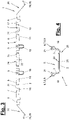
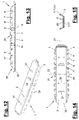
- Figure 1 to 9 show the connector (1) in different views.
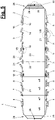
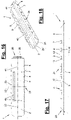
- Figure 10 and 11 the plug-in position of the connector (1) is shown on one side in one end of a hollow profile (32).
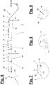
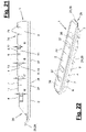
- Figure 12 to 25 show four other variants of the connector (1).
- the connector (1) is designed as a straight connector. Alternatively, it can be designed as a corner bracket.
- the connector (1) has a center (22) and connector legs protruding therefrom in different directions. In the case of the straight connector shown, the connector legs are aligned. With a corner angle, they enclose an angle that deviates from 180°, e.g. 90°.
- the connector (1) also has a longitudinal axis (23) extending along its legs and transverse to the center or centerline (22).
- the connector (1) has a base (2) with side walls (3) on the edge. In the installed position of the connector or in the connector (31), the bottom (2) to Profile bottom (35) of the or the hollow profile (32) and the pane interior of the insulating glazing.
- the side walls (3) adjoin the longitudinal edges of the base (2) perpendicularly or preferably slightly angled outwards and protrude in the opposite direction to the hollow profile roof (36).
- the bottom (2) and the side walls (3) surround an inner cavity (5) which extends in the axial direction (22) to the open end faces (26) of the connector (1).
- the cavity (5) is free and allows the desiccant granules to flow axially over the joint of the ends of the hollow profile (32).
- the plug connector (1) has a substantially U-shape in cross section, which is open at the top towards the hollow profile roof (36) and towards the outside of the insulating glazing.
- the connector (1) is designed as a stamped and bent part made from sheet metal, in particular sheet steel.
- the sheet metal, in particular steel strip is preferably galvanized, e.g. electrolytically galvanized.
- the side walls or side bars (3) are punched out of a blank during production and bent off the base (2) or central bar.
- the preferably frame-shaped spacer of the insulating glazing can have one or more hollow profiles (32). It can consist, for example, of a single, multiple-bent hollow profile, the hollow profile ends of which are plugged onto the legs of the connector (1) on both sides.
- the spacer (frame) can be formed by several hollow profile pieces, which are connected to one another in a corresponding manner via an inserted plug connector (1). The junction can be on a straight section or on be arranged in a corner region of the spacer frame. The spacer (frame) distances neighboring glass panes of the insulating glazing.
- figure 1 shows the connector (1) in the first variant in a perspective view and in Figure 3, 4 and 5 in folded views.
- the connector (1) in the embodiment of Figure 1 to 11 has a closed and preferably level base (2) on whose end faces (26) base strips (28) are arranged.
- the bottom (2) has no openings and no retaining elements. He is according to the front view of figure 11 flat on the profile base (35), which is also flat on the inside.
- the plug connector (1) has resilient retaining elements (6,7,8,9) on the free edge (4) of its side walls (3), which protrude from their respective side wall (3) and are bent laterally outwards at an angle. These retaining elements (6,7,8,9) are designed as spring lugs, which are each directed towards the center (22) of the connector, starting from the side wall (3).
- the two side walls (3) have a row of four retaining elements (6,7,8,9) in front of and behind the middle of the connector (22).
- the retaining elements (6,7,8,9) are arranged at the same height on both sides of the longitudinal axis (23) and each form a pair with one another.
- the two legs of the connector (1) each have four such pairings.
- the four rows or groups of retaining elements (6,7,8,9) are of the same design.
- the retaining elements (6,7,8,9) are cut free from a plate with an angled, L-shaped punch cut from the free edge area (4) of the side walls (3) and then bent outwards.
- a wall extension (17) of the side wall (3) axially adjoining the bending point (10) remains.
- the retaining elements (6,7,8,9) have in the side view according to figure 3 and 6 seen in each case a straight lower edge (11).
- the lower edge (11) runs parallel to the floor (2) and to the longitudinal axis (23).
- the retaining elements (6,7,8,9) also have a straight upper edge (12) which also runs parallel to the bottom (2). It merges into the upper edge of the associated wall extension (17).
- the positions of the lower edge (11) and upper edge (12) refer to the installation position and the floor (2) underneath.
- the lower edge (11) is arranged closer to the floor (2) than the upper edge (12).
- the top edge (12) is on the free edge (4).
- the retaining elements (6,7,8,9) On the cut-out front, the retaining elements (6,7,8,9) have a straight and upright front edge (13) which extends parallel to the main plane of the side wall (3).
- the front edge (13) is aligned at right angles to the top and bottom edges (12,11) and can be rounded off at the respective edge transition.
- the retaining elements (6,7,8,9) are bent laterally around a rear bending point or bending edge (10) from the respective side wall (3) and are exhibited.
- the bending line (10) runs parallel to the front edge (13).
- the height of the retaining elements (6,7,8,9) is constant over their length.
- the retaining elements (6,7,8,9) have a rectangular shape in the side view, which is delimited by the edges (11,12,13) and the bending line (10).
- the length of the Retaining elements (6,7,8,9) along the upper and lower edge (12,11) is greater than the height of the retaining elements (6,7,8,9) along the front edge (13) or the bending line (10) .
- the length can, for example, be one third or one half greater than the height. Alternatively, the difference in length versus height may be even greater.
- the area size and the edge dimensions of the retaining elements (6,7,8,9) can be the same or different.
- the retaining elements (6) adjacent to the end faces (26) according to FIG figure 6 each have a smaller length and a greater height than the other retaining elements (7,8,9).
- Their lengths and heights as well as surface sizes can be the same as one another or only slightly different.
- the retaining elements (6,7,8,9) are separated from their respective side wall (3) on their underside or lower edge (11) by a straight axial separating cut (14).
- This is a narrow parting cut. Its width can be determined by the required punching or cutting tool.
- the separating cut (14) extends parallel to the base (2) and to the longitudinal axis (23).
- One end of the separating cut or free cut (14) extends to the bending line (10). He has a sharp edge here.
- the straight and narrow severing cut (14) has a much smaller width than in the prior art mentioned at the outset and also does not have the enlarged and rounded opening at the said end of the cut.
- the side wall (3) Adjoining the bending point (10) and the retaining elements (6,7,8,9), the side wall (3) has said wall extension (17) in the direction of the adjacent end face (26). Furthermore, the side wall (3) has a free space (15) in front of the front edge (13) of the retaining elements (6,7,8,9). This space (15) consists between the front edge (13) and the upright edge of the adjacent wall extension (17) of the next retaining element (7,8,9). The upright elongated space (15) is oriented across the floor (2). It is wider than the horizontal separating cut (14). The free space (15) has a groove (16) in the side wall (3) on the underside, which extends a little below the separating cut (14). figure 3 and 6 clarify this training.
- the two side walls (3) each have a row of several, preferably four, retaining elements (6,7,8,9) on either side of the connector center (22).
- the above-mentioned pairs of retaining elements (6,7,8,9) lying opposite one another each have a deployment width (w6,w7,w8,w9).
- the projection widths (w6, w7, w8, w9) are of different sizes and each increase from the end face (26) to the middle of the connector (22).
- the extension widths relate to the outermost upright edges or front edges (13) of the retaining elements (6,7,8,9) and in each case to the upper end and the end furthest away from the floor (2).
- the pair of retaining elements (6) closest to the end face (26) has the smallest deployment width (w6).
- the following pairs of restraining elements (7,8,9) each have a larger deployment width (w7, w8, w9).
- the difference in size between the opening width (w6) and the following opening width (w7) is greater than the respective difference between the opening widths (w7,w8,w9).
- This first difference between the projection widths (w6,w7) can be approx. 1 mm.
- the difference in width between the following projection widths (w7,w8,w9) is much smaller and is approx. 0.1 mm.
- the opening width (w9) closest to the connector center (22) is the largest.
- the retaining elements (7, 8, 9) arranged on both sides of the connector center (22) on the side walls (3) or the connector legs have different heights (h1, h2) above the floor (2).
- the heights (h1, h2) relate to the distance between the lower edge of the floor (2) and the upper edge (12) of the retaining elements (6,7,8,9).
- the retaining element (6) arranged on the end face (26) has a lower height (h1) than the other retaining elements (7, 8, 9) following in the axial direction towards the center (22) of the connector. Their height (h2) is greater than the height (h1).
- the separating cuts (14) or the lower edges (11) are arranged lower on the front retaining element (6) than on the other retaining elements (7, 8, 9).
- the other retaining elements (7,8,9) can have the same height (h2) as one another. Their straight upper edges (12) and the likewise straight upper edges of their wall extensions (17) and the lower edges (11) are each at the same height. Alternatively, the height of the retaining elements (7) can be somewhat smaller and represent an intermediate height. The difference between the heights (h1) and (h2) can be about 0.3 mm, for example.
- the side walls (3) on both sides of the connector center (22) can each have an embossing (18).
- embossings (18) are present on the two connector legs in a center-symmetrical arrangement.
- the trough-like embossings (18) are each directed outwards and preferably have an elongated and upright shape directed transversely to the base (2).
- the sidewall material bulges outwardly and may be flat or slightly curved in the central bulge area.
- the embossings (18) are each arranged in the area of a retaining element. They are preferably located on the retaining element (9) closest to the connector center (22). The embossing (18) is introduced into the circuit board during connector manufacture before the retaining element (9) is bent and laterally deployed.
- the embossing (18) is interrupted by the separating cut (14).
- the embossing (18) has an embossing area (19) on the side wall (3) and an embossing area (20) on the deployed retaining element (9). Seen in the longitudinal direction (23), the embossed areas (19, 20) are laterally offset from one another as a result of the said exhibition.
- figure 2 explains this training.
- figure 7 shows the embossing (18) viewed from the bottom (2).
- the connector (1) can have an inwardly directed blocking element (21) on each of the side walls (3).
- the blocking element (21) is designed as a blocking lug bent at an angle and directed towards the cavity (5) and is arranged on a wall extension (17) after a retaining element (8).
- a blocking element (21) is arranged on each of the side walls (3).
- the locking elements (21) are located on different legs and are offset diagonally to the connector center (22).
- the blocking elements (21) narrow access to the cavity (5) from above and prevent plug connectors (1) from being immersed and nested in one layer on top of the other.
- the bottom tongues (28) each have a stabilizer (29).
- the stabilization (29) acts mechanically and stiffens the outer or front tongue edge (30).
- the stabilization (29) can, for example, as an entanglement according to figure 5 and 9 be trained.
- a separating cut is made in the middle and in the longitudinal direction (23) in the edge of the tongue (30), with the resulting tongue edge sections then being interlaced with one another and bent upwards and downwards in opposite directions.
- the connector (1) has a center finder (24), which is designed, for example, as a center stop with fixed and/or resilient stop elements (25) for the plugged-on hollow profile ends (32). There are different design variants for this.
- the stop elements (25) are arranged on one, preferably both, side walls (3). They are each designed as pairs of spring lugs that are directed towards one another and are laterally outwards. They are arranged in pairs opposite one another on both sides of the connector center (22). They are also axially spaced from each other at their fronts.
- the stop elements (25) are arranged, for example, on the free edge area (4) of the side walls (3). They can be cut out of the respective side wall and bent obliquely outwards.
- figure 2 and 3 show the details of the center stop (24) and its stop elements (25).
- a hollow profile end (32) pushed onto one connector leg runs over the first elastically yielding stop element (25) and strikes beyond the center (22) on the end face of the second stop element (25) directed in the opposite direction and acting as a stop.
- the second end (32) of the hollow section pushed on from the opposite side then strikes the first end (32) of the hollow section at the front.
- the meeting point of the two The ends (32) of the hollow profile are located in the area of the center (22) of the connector (1) and are covered and sealed by the plate-like base (2) at least in the base area.
- a spring nose can be combined with a fixed stop located opposite the center (22).
- a fixed stop located opposite the center (22).
- a center finder (24) can also be designed in a different way and can also be arranged at a different point on the connector (1). In the case of a corner bracket, the corner area is correspondingly widened and reinforced to form a stop for the plugged-on hollow profiles (32).
- Figure 10 and 11 illustrate the plug connection (31) and the design of the hollow profile or profiles (32).
- the hollow profile or profiles (32) are preferably designed as a warm-edge hollow profile. They consist at least partially of a plastic area with high thermal insulation. They can also have an area made of a different material, in particular metal.
- the connector (1) inserted into the end of the profile preferably comes into contact primarily with the plastic area.
- the hollow profile (32) has, for example, a substantially rectangular cross-section with a profile base (35), profile roof (36) and side walls.
- the profile base (35) and the base (2) of the connector (1) face the inside of the spacer frame and the pane interior of the insulating glazing.
- the cross-sectional shape of the connector (1) is that of the hollow profile (32) and together with the retaining elements (6,7,8,9) offers a firm seat in the inserted position.
- the hollow profile (32) is designed in several parts and consists, for example, of two profile parts (33, 34).
- One profile part (33) is made of plastic and the other profile part (34) is made of metal, in particular stainless steel.
- the profile part (33) is e.g. trough-shaped and forms the lower part of the hollow profile (32).
- the other profile part (34) is shell-shaped and designed like a cover. It is made of said metal.
- the lower part (33) made of plastic forms the profile base (35) and the side walls of the hollow profile (32).
- the metallic upper part (34) forms the profile roof (36) and overlaps the opening of the lower part (33) and the cavity (5) of the connector (1), which is open towards the roof area.
- the upper part (34) can be designed like a clamp and can also overlap an area of the side walls of the lower part (33) and snap into a local recess with a projection and be received resiliently.
- the closed and, for example, flat bottom (2) of the connector (1) lies flat on the likewise flat profile base (35) and bridges the connection point of the hollow profile ends (32).
- a granulated desiccant is allowed to flow through the cavity (5) and across the joint.
- the sealing against undesired inflow of granules to the connection point takes place through the aforementioned ground contact and through the lateral embossings (18).
- Figure 12 to 25 show variants of the straight connector (1). They largely agree with the first variant of Figure 1 to 11 match, in particular with regard to the rectangular shape of the lateral retaining elements (6,7,7,9) with a straight lower and upper edge (11,12) and an upright front edge (13). The changes are explained below.
- Figure 12 to 15 show a second variant of the straight connector (1) in a perspective view of figure 12 and in side, plan and end views of Figure 13 to 15 .
- the connector (1) of the second variant differs from the first variant in the arrangement of resilient retaining elements (37) on the base (2). These are designed as resilient bottom lugs, which are cut out of the bottom (2) and bent.
- the retaining elements (37) are each directed obliquely outwards and point towards the center of the connector (22). The retaining elements (37) can thereby engage with the profile base (35) and claw here.
- At least one retaining element (37) is arranged on each side of the center (22) of the connector on the bottom (2) of the connector (1). In the exemplary embodiment shown, there are two retaining elements (37) on each side.
- the retaining elements (37) have a short length as seen in the axial direction (23). Its length is shorter than its width, in particular its width at the free end edge (38).
- the retaining elements or bottom lugs (37) can have a conical shape when viewed from above, which widens toward the free end edge (38). The transition point or bending point on the floor (2) is narrower than the free end edge (38).
- the locking elements (21) of the first variant are missing. Alternatively, they may be present.
- the embossing (18) of the first variant is present in a modified form. They only reach as far as the separating cut (14) and do not extend into the lateral retaining element (9).
- Figure 16 to 18 illustrate a third variant of the straight connector (1) in top view and side view of Figure 16 and 17 and in perspective view from figure 18 .
- the connector shown here (1) again has a closed bottom (2).
- the floor (2) there is a central channel (41) running in the longitudinal direction (23).
- the base (2) curves inwards towards the cavity (5).
- a central row of perforations in the profile base (35) can be accommodated in the channel (41).
- Bead-like depressions (40) are arranged on both sides of the channel (41) and also run in the longitudinal direction (23). They are shorter than the connector length and are located in the middle of the connector (22).
- the axial grooves (41) can bring about a stiffening of the floor (2) in the middle area.
- the plug connector (1) when plugged in, can thus better absorb bending forces and bending moments that can occur when handling the spacer frame formed by the hollow profile (32).
- figure 17 shows the design of the retaining elements (6,7,8,9) on the free edge (4) of the side walls (3) in a side view.
- This design is the same in variants (1,2,3).
- the retaining elements (6,7,8,9) have in accordance with figure 5 and 6 the said height (h1,h2) and the said opening widths (w6,w7,w8,w9).
- the length of the upstanding leading edges (13) of the retaining elements (6,7,8,9) is essentially the same size.
- the front edge length of the resilient stop lugs (25) of the center finder (24) can also have the same size.
- the embossing (18) and the locking elements (21) of the first variant are missing. Alternatively, they may be present.
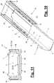
- Figure 19 to 22 illustrate a fourth variant of the straight connector (1) in a side view and a folded top view of Figure 19 and 20 .
- figure 21 shows a broken and enlarged representation of the detail XXI of figure 19 .
- figure 22 is a perspective view of the connector (1).
- the base (2) has two resilient retaining elements (37) of the type described above on both sides of the connector center (22).
- the retaining elements (38) are slightly longer than in the second variant.
- the base (2) has an outwardly directed elevation (39). It runs the length of the connector (1) and is located in its central area. It forms an outwardly protruding, rectangular base on the floor (2), which springs back again at the edges.
- the bottom lugs (37) are arranged on the elevation (39).
- the lateral retaining elements (6,7,8,9) on the free edge (4) of the side walls (3) have in principle the same rectangular shape as in the first three variants.
- One difference is the length of the upstanding front edges (13).
- the retaining elements (9) closest to the connector center (22) each have a smaller leading edge length (19). (13) as the front edge lengths (18,17,15) of the retaining elements (8,7,6) following in the direction of the end face (26).
- the upper edges (12) of the retaining elements (7,8,9) are located accordingly figure 6 each at the same height (h2).
- the shortened front edge length (19) causes the side wall (3) on the retaining element (9) to have a greater web height from the base (2) to the lower edge (11) or to the separating cut (14) than in the other retaining elements (6,7, 8) has.
- the connector (1) is stiffened in the area near the center of the connector (22) due to the greater web height. Due to the shortened front edge length (19) and the correspondingly shorter bending point (10), the retaining element (9) is more flexible than the other retaining elements (6,7,8).
- the length of the front edge (19) is essentially the same as the length of the front edge of the resilient stop lugs (25) on the center location (24).
- figure 20 illustrates another modification of the fourth variant.
- the lateral deployment width (w9) of the lateral retaining elements (9) closest to the center of the connector and the deployment width (wm) of the resilient stop lugs (25) can be the same.
- the deployment width (wm) of the stop lugs (25) can also be smaller than the deployment width (w9).
- the other opening widths (w6,w7,w8) are sized according to the first variant and figure 5 graded. For the sake of clarity, they are not shown in the fourth variant.
- the embossing (18) and the locking elements (21) of the first variant are missing in the fourth variant. Alternatively, they may be present.
- Figure 23 to 25 illustrate a fifth variant of the connector.
- figure 24 shows a bottom view.
- figure 23 show a perspective bottom view of the connector (1) and figure 25 a top perspective view of the open cavity.
- the connector (1) again has a central elevation (39) on the base (2), which forms a base that protrudes outwards from the base (2) and has a substantially rectangular contour. Furthermore, a retaining element (37) and a further elevation in the form of a transverse bar (42) are arranged on the floor (2) on both sides of the connector center (22).
- the bolt (42) is adjacent to the end face (26) in each case, with the retaining element (37) being located between the bolt (42) and the central elevation (39).
- the central elevation (39) and the bars (42) can have a depression or recess in the middle.
- a central row of perforations on the profile base (35) can be accommodated here.
- the free end edge of the retaining elements (37) can also have such a recess.
- the embossing (18) and the locking elements (21) of the first variant are missing in the fifth variant. Alternatively, they may be present.
- the design of the outer surface of the connector base (2) and the inner surface of the profile base (35) can be adapted to one another.
- the one shown in the other variants adapted, in particular complementary, contouring with peaks and valleys may be present.
- the number of retaining elements (6,7,8,9) on the connector legs or in the row arrangements on the side walls (3) on both sides of the connector center (22) is also variable.
- the ratios between the projection widths (w6,w7,w8,w9) and the heights (h1,h2) can also be variable.
- the plug connection (31) and the hollow profile (32) can also be modified. It can have a different cross-sectional shape and a different material, for example a light metal alloy, steel, stainless steel or the like. It can be produced, for example, as an extruded profile or rolled profile.
Landscapes
- Engineering & Computer Science (AREA)
- Civil Engineering (AREA)
- Structural Engineering (AREA)
- Connector Housings Or Holding Contact Members (AREA)
- Joining Of Building Structures In Genera (AREA)
- Finishing Walls (AREA)
- Securing Of Glass Panes Or The Like (AREA)
Claims (15)
- Connecteur enfichable droit, pour profilés creux (23), notamment profilés creux à bord chaud (Warm Edge), d'entretoises d'un vitrage isolant, le connecteur enfichable (1) présentant une section transversale essentiellement en forme de U avec des côtés frontaux ouverts (26) et un fond (2) orienté vers l'espace intérieur de la vitre en position de montage, ainsi que des parois latérales (3) du côté du bord et un organe de centrage (24), des éléments de retenue élastiques (6, 7, 8, 9), en saillie latéralement, étant agencés sur le bord libre (4) des parois latérales (3), caractérisé en ce que les éléments de retenue (6, 7, 8, 9) présentent en vue latérale une forme rectangulaire et un bord inférieur droit (11).
- Connecteur enfichable selon la revendication 1, caractérisé en ce que les éléments de retenue (6, 7, 8, 9) présentent un bord avant droit et vertical (13) qui s'étend parallèlement au plan principal de la paroi latérale (3), le bord inférieur (11) étant parallèle au fond (2).
- Connecteur enfichable selon l'une quelconque des revendications précédentes, caractérisé en ce que la paroi latérale (3) présente à chaque fois un espace libre (15) devant le bord avant (13) des éléments de retenue (6, 7, 8, 9), l'espace libre (15) présentant sur le côté inférieur une gorge (16) qui s'étend sous la coupe de séparation (14).
- Connecteur enfichable selon l'une quelconque des revendications précédentes, caractérisé en ce que les paires d'éléments de retenue (6, 7, 8, 9) situées en vis-à-vis des deux côtés de l'axe longitudinal central (23) du connecteur enfichable (1) présentent des largeurs de saillie différentes (w6, w7, w8, w9), qui augmentent à chaque fois depuis le côté frontal (26) vers le centre du connecteur (22).
- Connecteur enfichable selon l'une quelconque des revendications précédentes, caractérisé en ce que les éléments de retenue (6, 7, 8, 9) agencés des deux côtés du centre du connecteur (22) sur les parois latérales (3) présentent des hauteurs différentes (h1, h2) au-dessus du fond (2).
- Connecteur enfichable selon l'une quelconque des revendications précédentes, caractérisé en ce que l'élément de retenue (9) respectivement le plus proche par rapport au centre du connecteur (22) présente une longueur plus courte (19) de son bord avant (13) que les autres éléments de retenue (6, 7, 8) qui suivent dans la direction du côté frontal (26) .
- Connecteur enfichable selon l'une quelconque des revendications précédentes, caractérisé en ce que les parois latérales (3) des deux côtés du centre du connecteur (22) présentent respectivement un relief (18) dirigé vers l'extérieur, de préférence allongé et vertical.
- Connecteur enfichable selon l'une quelconque des revendications précédentes, caractérisé en ce qu'un élément de blocage (21) dirigé vers l'intérieur est agencé à chaque fois sur les parois latérales (3).
- Connecteur enfichable selon l'une quelconque des revendications précédentes, caractérisé en ce que le connecteur enfichable (1) présente à chaque fois sur les côtés frontaux (26) une languette de fond (28) avec une stabilisation (29), notamment un entrelacement du bord extérieur de la languette (30) .
- Connecteur enfichable selon l'une quelconque des revendications précédentes, caractérisé en ce que le connecteur enfichable (1) présente un fond fermé (2) ou présente sur le fond (2) un ou plusieurs éléments de retenue élastiques (37), qui sont respectivement dirigés en oblique vers l'extérieur et orientés vers le centre du connecteur (22).
- Connecteur enfichable selon l'une quelconque des revendications précédentes, caractérisé en ce que le connecteur enfichable (1) est réalisé sous forme de pièce découpée et pliée dans une tôle métallique, notamment dans une bande d'acier galvanisée.
- Connexion enfichable d'entretoises d'un vitrage isolant, la connexion enfichable (31) présentant un profilé creux (23) et un connecteur enfichable enfiché (1), caractérisée en ce que le connecteur enfichable (1) est réalisé selon l'une quelconque des revendications 1 à 11.
- Connexion enfichable selon la revendication 12, caractérisée en ce que le profilé creux (32) est réalisé sous forme de profilé creux à bord chaud (Warm Edge).
- Connexion enfichable selon la revendication 12 ou 13, caractérisée en ce que le fond (2) du connecteur enfichable (1) est agencé sur le fond de profilé (35) du profilé creux (32) qui est orienté vers l'espace intérieur du vitrage isolant.
- Procédé de fabrication d'un connecteur enfichable droit (1) pour profilés creux (23), notamment profilés creux à bord chaud (Warm Edge), d'entretoises d'un vitrage isolant, le connecteur enfichable (1) présentant une section transversale essentiellement en forme de U avec des côtés frontaux ouverts (26) et un fond (2) orienté vers l'espace intérieur de la vitre en position de montage, ainsi que des parois latérales (3) du côté du bord et un organe de centrage (24), des éléments de retenue élastiques (6, 7, 8, 9), en saillie latéralement, étant agencés sur le bord libre (4) des parois latérales (3), caractérisé en ce que les éléments de retenue (6, 7, 8, 9) sont dégagés par découpage dans la paroi latérale respective (3) sur le bord libre (4) de telle sorte qu'ils présentent en vue latérale une forme rectangulaire et un bord inférieur droit (11).
Applications Claiming Priority (2)
| Application Number | Priority Date | Filing Date | Title |
|---|---|---|---|
| DE202017101315.4U DE202017101315U1 (de) | 2017-03-08 | 2017-03-08 | Steckverbinder und Steckverbindung |
| PCT/EP2018/055654 WO2018162584A1 (fr) | 2017-03-08 | 2018-03-07 | Connecteur d'assemblage et liaison par connecteur d'assemblage |
Publications (2)
| Publication Number | Publication Date |
|---|---|
| EP3592932A1 EP3592932A1 (fr) | 2020-01-15 |
| EP3592932B1 true EP3592932B1 (fr) | 2022-09-14 |
Family
ID=61750077
Family Applications (1)
| Application Number | Title | Priority Date | Filing Date |
|---|---|---|---|
| EP18712517.4A Active EP3592932B1 (fr) | 2017-03-08 | 2018-03-07 | Connecteur d'assemblage et liaison par connecteur d'assemblage |
Country Status (11)
| Country | Link |
|---|---|
| US (1) | US11555347B2 (fr) |
| EP (1) | EP3592932B1 (fr) |
| CN (1) | CN110431282A (fr) |
| DE (2) | DE202017101315U1 (fr) |
| DK (1) | DK3592932T3 (fr) |
| ES (1) | ES2933509T3 (fr) |
| HU (1) | HUE060790T2 (fr) |
| PL (1) | PL3592932T3 (fr) |
| RU (1) | RU2765352C2 (fr) |
| UA (1) | UA127860C2 (fr) |
| WO (1) | WO2018162584A1 (fr) |
Families Citing this family (6)
| Publication number | Priority date | Publication date | Assignee | Title |
|---|---|---|---|---|
| DE202014105547U1 (de) * | 2014-11-19 | 2016-02-22 | Max Kronenberg | Steckverbinder und Steckverbindung |
| PL244055B1 (pl) | 2019-03-29 | 2023-11-27 | Grzywacz Cezary P P H U Plastmax | Łącznik wtykowy do łączenia końcówek profili okiennych |
| PL244056B1 (pl) | 2019-03-29 | 2023-11-27 | Grzywacz Cezary P P H U Plastmax | Łącznik wtykowy do łączenia końcówek profili okiennych |
| DE202020102626U1 (de) | 2020-05-11 | 2021-07-23 | Ralf M. Kronenberg | Erfassungsmodul |
| DE202021102028U1 (de) | 2021-04-15 | 2022-07-19 | Ralf M. Kronenberg | Steckverbinder und Steckverbindung |
| DE202022100100U1 (de) | 2022-01-10 | 2023-04-19 | Ralf M. Kronenberg | Steckverbinder |
Citations (6)
| Publication number | Priority date | Publication date | Assignee | Title |
|---|---|---|---|---|
| US3643989A (en) | 1969-10-29 | 1972-02-22 | Erich Sattler | Dowel for extruded sections of plastics material |
| DE3408600A1 (de) | 1984-03-09 | 1985-09-12 | Hans Joachim 5650 Solingen Kronenberg | Verbinder fuer hohlprofile |
| EP1317601B1 (fr) | 2000-09-13 | 2004-08-04 | Max Kronenberg | Raccords a emboitement pour profiles creux |
| DE202006009491U1 (de) | 2006-06-14 | 2007-10-25 | Kronenberg, Max | Steckverbinder |
| PL65674Y1 (pl) | 2009-08-10 | 2011-11-30 | Halina Nasiadko | Łącznik prosty do szyb zespolonych |
| DE202014104222U1 (de) | 2014-09-08 | 2015-12-11 | Max Kronenberg | Steckverbinder |
Family Cites Families (14)
| Publication number | Priority date | Publication date | Assignee | Title |
|---|---|---|---|---|
| DE9411067U1 (de) | 1994-07-07 | 1994-09-15 | Kronenberg, Max, 42657 Solingen | Steckverbinder für Hohlprofile |
| JP2007509262A (ja) | 2003-10-22 | 2007-04-12 | サン−ゴバン グラス フランス | 箱状中空形材の二つの端領域用の連結要素 |
| DE202004013686U1 (de) * | 2004-08-31 | 2006-01-05 | Kronenberg, Max | Gerader Steckverbinder |
| ES2356076T3 (es) * | 2005-08-01 | 2011-04-04 | TECHNOFORM CAPRANO UND BRUNNHOFER GMBH & CO. KG | Disposición de separador con conector fusionable para unidades de vidrio aislante. |
| DK1785575T3 (da) * | 2005-10-20 | 2010-04-19 | Ralf Max Kronenberg | Stikforbinder |
| DE202007004924U1 (de) | 2007-04-02 | 2008-08-14 | Kronenberg, Ralf Max | Steckverbinder |
| DE202008013046U1 (de) * | 2008-10-02 | 2010-02-25 | Kronenberg, Max | Steckverbinder |
| CN201276943Y (zh) * | 2008-10-28 | 2009-07-22 | 王贤明 | 直插件 |
| NL1036410C2 (en) * | 2009-01-12 | 2010-07-13 | Wavin Bv | Push-fit pipe connector with improved gripping assembly. |
| DE102012106676A1 (de) * | 2011-07-24 | 2013-01-24 | Cera Handelsgesellschaft Mbh | Steckverbinder |
| DE202014105547U1 (de) * | 2014-11-19 | 2016-02-22 | Max Kronenberg | Steckverbinder und Steckverbindung |
| DE202015105061U1 (de) * | 2015-09-24 | 2016-12-29 | Ralf M. Kronenberg | Steckverbinder und Steckverbindung |
| WO2017205256A1 (fr) * | 2016-05-26 | 2017-11-30 | Apogee Enterprises, Inc. | Clavette d'espacement pour sections d'espacement creuses d'une unité à verre isolant |
| PL244055B1 (pl) * | 2019-03-29 | 2023-11-27 | Grzywacz Cezary P P H U Plastmax | Łącznik wtykowy do łączenia końcówek profili okiennych |
-
2017
- 2017-03-08 DE DE202017101315.4U patent/DE202017101315U1/de active Active
-
2018
- 2018-03-07 WO PCT/EP2018/055654 patent/WO2018162584A1/fr unknown
- 2018-03-07 UA UAA201910021A patent/UA127860C2/uk unknown
- 2018-03-07 DE DE102018105264.2A patent/DE102018105264A1/de active Pending
- 2018-03-07 CN CN201880016962.2A patent/CN110431282A/zh active Pending
- 2018-03-07 ES ES18712517T patent/ES2933509T3/es active Active
- 2018-03-07 US US16/491,801 patent/US11555347B2/en active Active
- 2018-03-07 DK DK18712517.4T patent/DK3592932T3/da active
- 2018-03-07 HU HUE18712517A patent/HUE060790T2/hu unknown
- 2018-03-07 RU RU2019130842A patent/RU2765352C2/ru active
- 2018-03-07 EP EP18712517.4A patent/EP3592932B1/fr active Active
- 2018-03-07 PL PL18712517.4T patent/PL3592932T3/pl unknown
Patent Citations (7)
| Publication number | Priority date | Publication date | Assignee | Title |
|---|---|---|---|---|
| US3643989A (en) | 1969-10-29 | 1972-02-22 | Erich Sattler | Dowel for extruded sections of plastics material |
| DE3408600A1 (de) | 1984-03-09 | 1985-09-12 | Hans Joachim 5650 Solingen Kronenberg | Verbinder fuer hohlprofile |
| EP1317601B1 (fr) | 2000-09-13 | 2004-08-04 | Max Kronenberg | Raccords a emboitement pour profiles creux |
| DE202006009491U1 (de) | 2006-06-14 | 2007-10-25 | Kronenberg, Max | Steckverbinder |
| PL65674Y1 (pl) | 2009-08-10 | 2011-11-30 | Halina Nasiadko | Łącznik prosty do szyb zespolonych |
| DE202014104222U1 (de) | 2014-09-08 | 2015-12-11 | Max Kronenberg | Steckverbinder |
| WO2016038002A1 (fr) | 2014-09-08 | 2016-03-17 | Kronenberg Ralf M | Connecteur enfichable |
Also Published As
| Publication number | Publication date |
|---|---|
| EP3592932A1 (fr) | 2020-01-15 |
| WO2018162584A1 (fr) | 2018-09-13 |
| ES2933509T3 (es) | 2023-02-09 |
| PL3592932T3 (pl) | 2023-01-23 |
| US11555347B2 (en) | 2023-01-17 |
| RU2019130842A (ru) | 2021-04-08 |
| DE202017101315U1 (de) | 2018-06-11 |
| UA127860C2 (uk) | 2024-01-31 |
| HUE060790T2 (hu) | 2023-04-28 |
| US20210131166A1 (en) | 2021-05-06 |
| DK3592932T3 (da) | 2022-12-12 |
| DE102018105264A1 (de) | 2018-09-13 |
| CN110431282A (zh) | 2019-11-08 |
| RU2019130842A3 (fr) | 2021-06-28 |
| RU2765352C2 (ru) | 2022-01-28 |
Similar Documents
| Publication | Publication Date | Title |
|---|---|---|
| EP3592932B1 (fr) | Connecteur d'assemblage et liaison par connecteur d'assemblage | |
| EP2606187B1 (fr) | Élément de recouvrement composé de plusieurs grilles insérées les unes dans les autres | |
| EP2281994B1 (fr) | Raccord pour profilés intercalaires creux de vitrages isolants | |
| EP3191671B1 (fr) | Connecteur enfichable | |
| EP3353366B1 (fr) | Connecteur et connexion à emboîtement | |
| DE112013003263B4 (de) | Steckverbinder und Steckverbindung | |
| EP2334887B1 (fr) | Connecteur à fiche | |
| EP1785575B1 (fr) | Connecteur | |
| DE9216955U1 (de) | Steckverbinder für Hohlprofile | |
| DE202016105953U1 (de) | Einfassung von Rasenflächen und Beeten | |
| DE202006009491U1 (de) | Steckverbinder | |
| EP0916013B2 (fr) | Element de liaison enfichable pour ecarteur de plaques de verre isolant | |
| WO2016079220A1 (fr) | Fiche et connexion enfichable | |
| EP2397641B1 (fr) | Connecteur à fiches | |
| DE29716378U1 (de) | Steckverbinder für Hohlprofile | |
| DE202020107095U1 (de) | Steckverbinder | |
| EP4074934B1 (fr) | Connecteur enfichable et connexion enfichable | |
| DE202019102085U1 (de) | Steckverbinder und Steckverbindung | |
| AT413414B (de) | Metallschindel-abdeckung für dächer oder fassaden | |
| DE3610377C2 (fr) | ||
| EP0798818B1 (fr) | Boítier pour prises multiples | |
| EP1643045A2 (fr) | Raccord de poutre invisible | |
| DE202023102210U1 (de) | Steckverbinder | |
| DE102004054678A1 (de) | Einstückiges Gegenkontaktelement für einen elektrischen Flachstecker |
Legal Events
| Date | Code | Title | Description |
|---|---|---|---|
| STAA | Information on the status of an ep patent application or granted ep patent |
Free format text: STATUS: UNKNOWN |
|
| STAA | Information on the status of an ep patent application or granted ep patent |
Free format text: STATUS: THE INTERNATIONAL PUBLICATION HAS BEEN MADE |
|
| PUAI | Public reference made under article 153(3) epc to a published international application that has entered the european phase |
Free format text: ORIGINAL CODE: 0009012 |
|
| STAA | Information on the status of an ep patent application or granted ep patent |
Free format text: STATUS: REQUEST FOR EXAMINATION WAS MADE |
|
| 17P | Request for examination filed |
Effective date: 20191002 |
|
| AK | Designated contracting states |
Kind code of ref document: A1 Designated state(s): AL AT BE BG CH CY CZ DE DK EE ES FI FR GB GR HR HU IE IS IT LI LT LU LV MC MK MT NL NO PL PT RO RS SE SI SK SM TR |
|
| AX | Request for extension of the european patent |
Extension state: BA ME |
|
| DAV | Request for validation of the european patent (deleted) | ||
| DAX | Request for extension of the european patent (deleted) | ||
| GRAP | Despatch of communication of intention to grant a patent |
Free format text: ORIGINAL CODE: EPIDOSNIGR1 |
|
| STAA | Information on the status of an ep patent application or granted ep patent |
Free format text: STATUS: GRANT OF PATENT IS INTENDED |
|
| INTG | Intention to grant announced |
Effective date: 20220406 |
|
| GRAS | Grant fee paid |
Free format text: ORIGINAL CODE: EPIDOSNIGR3 |
|
| GRAA | (expected) grant |
Free format text: ORIGINAL CODE: 0009210 |
|
| STAA | Information on the status of an ep patent application or granted ep patent |
Free format text: STATUS: THE PATENT HAS BEEN GRANTED |
|
| AK | Designated contracting states |
Kind code of ref document: B1 Designated state(s): AL AT BE BG CH CY CZ DE DK EE ES FI FR GB GR HR HU IE IS IT LI LT LU LV MC MK MT NL NO PL PT RO RS SE SI SK SM TR |
|
| REG | Reference to a national code |
Ref country code: GB Ref legal event code: FG4D Free format text: NOT ENGLISH |
|
| REG | Reference to a national code |
Ref country code: CH Ref legal event code: EP |
|
| REG | Reference to a national code |
Ref country code: DE Ref legal event code: R096 Ref document number: 502018010626 Country of ref document: DE |
|
| REG | Reference to a national code |
Ref country code: IE Ref legal event code: FG4D Free format text: LANGUAGE OF EP DOCUMENT: GERMAN |
|
| REG | Reference to a national code |
Ref country code: AT Ref legal event code: REF Ref document number: 1518799 Country of ref document: AT Kind code of ref document: T Effective date: 20221015 |
|
| REG | Reference to a national code |
Ref country code: DK Ref legal event code: T3 Effective date: 20221208 |
|
| REG | Reference to a national code |
Ref country code: NL Ref legal event code: FP |
|
| REG | Reference to a national code |
Ref country code: LT Ref legal event code: MG9D |
|
| PG25 | Lapsed in a contracting state [announced via postgrant information from national office to epo] |
Ref country code: SE Free format text: LAPSE BECAUSE OF FAILURE TO SUBMIT A TRANSLATION OF THE DESCRIPTION OR TO PAY THE FEE WITHIN THE PRESCRIBED TIME-LIMIT Effective date: 20220914 Ref country code: RS Free format text: LAPSE BECAUSE OF FAILURE TO SUBMIT A TRANSLATION OF THE DESCRIPTION OR TO PAY THE FEE WITHIN THE PRESCRIBED TIME-LIMIT Effective date: 20220914 Ref country code: NO Free format text: LAPSE BECAUSE OF FAILURE TO SUBMIT A TRANSLATION OF THE DESCRIPTION OR TO PAY THE FEE WITHIN THE PRESCRIBED TIME-LIMIT Effective date: 20221214 Ref country code: LV Free format text: LAPSE BECAUSE OF FAILURE TO SUBMIT A TRANSLATION OF THE DESCRIPTION OR TO PAY THE FEE WITHIN THE PRESCRIBED TIME-LIMIT Effective date: 20220914 Ref country code: LT Free format text: LAPSE BECAUSE OF FAILURE TO SUBMIT A TRANSLATION OF THE DESCRIPTION OR TO PAY THE FEE WITHIN THE PRESCRIBED TIME-LIMIT Effective date: 20220914 Ref country code: FI Free format text: LAPSE BECAUSE OF FAILURE TO SUBMIT A TRANSLATION OF THE DESCRIPTION OR TO PAY THE FEE WITHIN THE PRESCRIBED TIME-LIMIT Effective date: 20220914 |
|
| REG | Reference to a national code |
Ref country code: ES Ref legal event code: FG2A Ref document number: 2933509 Country of ref document: ES Kind code of ref document: T3 Effective date: 20230209 |
|
| PG25 | Lapsed in a contracting state [announced via postgrant information from national office to epo] |
Ref country code: HR Free format text: LAPSE BECAUSE OF FAILURE TO SUBMIT A TRANSLATION OF THE DESCRIPTION OR TO PAY THE FEE WITHIN THE PRESCRIBED TIME-LIMIT Effective date: 20220914 Ref country code: GR Free format text: LAPSE BECAUSE OF FAILURE TO SUBMIT A TRANSLATION OF THE DESCRIPTION OR TO PAY THE FEE WITHIN THE PRESCRIBED TIME-LIMIT Effective date: 20221215 |
|
| PG25 | Lapsed in a contracting state [announced via postgrant information from national office to epo] |
Ref country code: SM Free format text: LAPSE BECAUSE OF FAILURE TO SUBMIT A TRANSLATION OF THE DESCRIPTION OR TO PAY THE FEE WITHIN THE PRESCRIBED TIME-LIMIT Effective date: 20220914 Ref country code: RO Free format text: LAPSE BECAUSE OF FAILURE TO SUBMIT A TRANSLATION OF THE DESCRIPTION OR TO PAY THE FEE WITHIN THE PRESCRIBED TIME-LIMIT Effective date: 20220914 Ref country code: PT Free format text: LAPSE BECAUSE OF FAILURE TO SUBMIT A TRANSLATION OF THE DESCRIPTION OR TO PAY THE FEE WITHIN THE PRESCRIBED TIME-LIMIT Effective date: 20230116 |
|
| REG | Reference to a national code |
Ref country code: HU Ref legal event code: AG4A Ref document number: E060790 Country of ref document: HU |
|
| PG25 | Lapsed in a contracting state [announced via postgrant information from national office to epo] |
Ref country code: SK Free format text: LAPSE BECAUSE OF FAILURE TO SUBMIT A TRANSLATION OF THE DESCRIPTION OR TO PAY THE FEE WITHIN THE PRESCRIBED TIME-LIMIT Effective date: 20220914 Ref country code: IS Free format text: LAPSE BECAUSE OF FAILURE TO SUBMIT A TRANSLATION OF THE DESCRIPTION OR TO PAY THE FEE WITHIN THE PRESCRIBED TIME-LIMIT Effective date: 20230114 Ref country code: EE Free format text: LAPSE BECAUSE OF FAILURE TO SUBMIT A TRANSLATION OF THE DESCRIPTION OR TO PAY THE FEE WITHIN THE PRESCRIBED TIME-LIMIT Effective date: 20220914 |
|
| REG | Reference to a national code |
Ref country code: DE Ref legal event code: R026 Ref document number: 502018010626 Country of ref document: DE |
|
| PLBI | Opposition filed |
Free format text: ORIGINAL CODE: 0009260 |
|
| PLAX | Notice of opposition and request to file observation + time limit sent |
Free format text: ORIGINAL CODE: EPIDOSNOBS2 |
|
| PG25 | Lapsed in a contracting state [announced via postgrant information from national office to epo] |
Ref country code: AL Free format text: LAPSE BECAUSE OF FAILURE TO SUBMIT A TRANSLATION OF THE DESCRIPTION OR TO PAY THE FEE WITHIN THE PRESCRIBED TIME-LIMIT Effective date: 20220914 |
|
| 26 | Opposition filed |
Opponent name: GRZYWACZ, CEZARY Effective date: 20230614 |
|
| PG25 | Lapsed in a contracting state [announced via postgrant information from national office to epo] |
Ref country code: SI Free format text: LAPSE BECAUSE OF FAILURE TO SUBMIT A TRANSLATION OF THE DESCRIPTION OR TO PAY THE FEE WITHIN THE PRESCRIBED TIME-LIMIT Effective date: 20220914 |
|
| PG25 | Lapsed in a contracting state [announced via postgrant information from national office to epo] |
Ref country code: MC Free format text: LAPSE BECAUSE OF FAILURE TO SUBMIT A TRANSLATION OF THE DESCRIPTION OR TO PAY THE FEE WITHIN THE PRESCRIBED TIME-LIMIT Effective date: 20220914 |
|
| PLAF | Information modified related to communication of a notice of opposition and request to file observations + time limit |
Free format text: ORIGINAL CODE: EPIDOSCOBS2 |
|
| PG25 | Lapsed in a contracting state [announced via postgrant information from national office to epo] |
Ref country code: LU Free format text: LAPSE BECAUSE OF NON-PAYMENT OF DUE FEES Effective date: 20230307 |
|
| PLBB | Reply of patent proprietor to notice(s) of opposition received |
Free format text: ORIGINAL CODE: EPIDOSNOBS3 |
|
| REG | Reference to a national code |
Ref country code: IE Ref legal event code: MM4A |
|
| PG25 | Lapsed in a contracting state [announced via postgrant information from national office to epo] |
Ref country code: IE Free format text: LAPSE BECAUSE OF NON-PAYMENT OF DUE FEES Effective date: 20230307 |
|
| PGFP | Annual fee paid to national office [announced via postgrant information from national office to epo] |
Ref country code: NL Payment date: 20240320 Year of fee payment: 7 |
|
| PGFP | Annual fee paid to national office [announced via postgrant information from national office to epo] |
Ref country code: AT Payment date: 20240318 Year of fee payment: 7 |
|
| PGFP | Annual fee paid to national office [announced via postgrant information from national office to epo] |
Ref country code: HU Payment date: 20240301 Year of fee payment: 7 Ref country code: CZ Payment date: 20240226 Year of fee payment: 7 Ref country code: DE Payment date: 20240321 Year of fee payment: 7 Ref country code: GB Payment date: 20240322 Year of fee payment: 7 |
|
| PGFP | Annual fee paid to national office [announced via postgrant information from national office to epo] |
Ref country code: TR Payment date: 20240226 Year of fee payment: 7 Ref country code: PL Payment date: 20240222 Year of fee payment: 7 Ref country code: FR Payment date: 20240320 Year of fee payment: 7 Ref country code: DK Payment date: 20240321 Year of fee payment: 7 Ref country code: BE Payment date: 20240320 Year of fee payment: 7 Ref country code: IT Payment date: 20240329 Year of fee payment: 7 |
|
| PGFP | Annual fee paid to national office [announced via postgrant information from national office to epo] |
Ref country code: CH Payment date: 20240401 Year of fee payment: 7 |
|
| PGFP | Annual fee paid to national office [announced via postgrant information from national office to epo] |
Ref country code: ES Payment date: 20240417 Year of fee payment: 7 |