EP3589166B1 - Bauplatte für eine möbelwand und verfahren zur herstellung einer solchen bauplatte und einer möbelwand - Google Patents
Bauplatte für eine möbelwand und verfahren zur herstellung einer solchen bauplatte und einer möbelwand Download PDFInfo
- Publication number
- EP3589166B1 EP3589166B1 EP18714132.0A EP18714132A EP3589166B1 EP 3589166 B1 EP3589166 B1 EP 3589166B1 EP 18714132 A EP18714132 A EP 18714132A EP 3589166 B1 EP3589166 B1 EP 3589166B1
- Authority
- EP
- European Patent Office
- Prior art keywords
- fitting
- construction panel
- core
- recess
- wall
- Prior art date
- Legal status (The legal status is an assumption and is not a legal conclusion. Google has not performed a legal analysis and makes no representation as to the accuracy of the status listed.)
- Active
Links
Images


Classifications
-
- A—HUMAN NECESSITIES
- A47—FURNITURE; DOMESTIC ARTICLES OR APPLIANCES; COFFEE MILLS; SPICE MILLS; SUCTION CLEANERS IN GENERAL
- A47B—TABLES; DESKS; OFFICE FURNITURE; CABINETS; DRAWERS; GENERAL DETAILS OF FURNITURE
- A47B96/00—Details of cabinets, racks or shelf units not covered by a single one of groups A47B43/00 - A47B95/00; General details of furniture
- A47B96/20—Furniture panels or like furniture elements
- A47B96/205—Composite panels, comprising several elements joined together
- A47B96/206—Composite panels, comprising several elements joined together with laminates comprising planar, continuous or separate layers
-
- A—HUMAN NECESSITIES
- A47—FURNITURE; DOMESTIC ARTICLES OR APPLIANCES; COFFEE MILLS; SPICE MILLS; SUCTION CLEANERS IN GENERAL
- A47B—TABLES; DESKS; OFFICE FURNITURE; CABINETS; DRAWERS; GENERAL DETAILS OF FURNITURE
- A47B96/00—Details of cabinets, racks or shelf units not covered by a single one of groups A47B43/00 - A47B95/00; General details of furniture
- A47B96/20—Furniture panels or like furniture elements
- A47B96/205—Composite panels, comprising several elements joined together
-
- E—FIXED CONSTRUCTIONS
- E05—LOCKS; KEYS; WINDOW OR DOOR FITTINGS; SAFES
- E05D—HINGES OR SUSPENSION DEVICES FOR DOORS, WINDOWS OR WINGS
- E05D15/00—Suspension arrangements for wings
- E05D15/26—Suspension arrangements for wings for folding wings
- E05D15/262—Suspension arrangements for wings for folding wings folding vertically
-
- E—FIXED CONSTRUCTIONS
- E05—LOCKS; KEYS; WINDOW OR DOOR FITTINGS; SAFES
- E05D—HINGES OR SUSPENSION DEVICES FOR DOORS, WINDOWS OR WINGS
- E05D15/00—Suspension arrangements for wings
- E05D15/40—Suspension arrangements for wings supported on arms movable in vertical planes
- E05D15/46—Suspension arrangements for wings supported on arms movable in vertical planes with two pairs of pivoted arms
-
- E—FIXED CONSTRUCTIONS
- E05—LOCKS; KEYS; WINDOW OR DOOR FITTINGS; SAFES
- E05D—HINGES OR SUSPENSION DEVICES FOR DOORS, WINDOWS OR WINGS
- E05D3/00—Hinges with pins
- E05D3/06—Hinges with pins with two or more pins
- E05D3/16—Hinges with pins with two or more pins with seven parallel pins and four arms
- E05D2003/163—Horizontal pivot-axis
-
- E—FIXED CONSTRUCTIONS
- E05—LOCKS; KEYS; WINDOW OR DOOR FITTINGS; SAFES
- E05Y—INDEXING SCHEME ASSOCIATED WITH SUBCLASSES E05D AND E05F, RELATING TO CONSTRUCTION ELEMENTS, ELECTRIC CONTROL, POWER SUPPLY, POWER SIGNAL OR TRANSMISSION, USER INTERFACES, MOUNTING OR COUPLING, DETAILS, ACCESSORIES, AUXILIARY OPERATIONS NOT OTHERWISE PROVIDED FOR, APPLICATION THEREOF
- E05Y2201/00—Constructional elements; Accessories therefor
- E05Y2201/10—Covers; Housings
-
- E—FIXED CONSTRUCTIONS
- E05—LOCKS; KEYS; WINDOW OR DOOR FITTINGS; SAFES
- E05Y—INDEXING SCHEME ASSOCIATED WITH SUBCLASSES E05D AND E05F, RELATING TO CONSTRUCTION ELEMENTS, ELECTRIC CONTROL, POWER SUPPLY, POWER SIGNAL OR TRANSMISSION, USER INTERFACES, MOUNTING OR COUPLING, DETAILS, ACCESSORIES, AUXILIARY OPERATIONS NOT OTHERWISE PROVIDED FOR, APPLICATION THEREOF
- E05Y2600/00—Mounting or coupling arrangements for elements provided for in this subclass
- E05Y2600/40—Mounting location; Visibility of the elements
- E05Y2600/41—Concealed
-
- E—FIXED CONSTRUCTIONS
- E05—LOCKS; KEYS; WINDOW OR DOOR FITTINGS; SAFES
- E05Y—INDEXING SCHEME ASSOCIATED WITH SUBCLASSES E05D AND E05F, RELATING TO CONSTRUCTION ELEMENTS, ELECTRIC CONTROL, POWER SUPPLY, POWER SIGNAL OR TRANSMISSION, USER INTERFACES, MOUNTING OR COUPLING, DETAILS, ACCESSORIES, AUXILIARY OPERATIONS NOT OTHERWISE PROVIDED FOR, APPLICATION THEREOF
- E05Y2600/00—Mounting or coupling arrangements for elements provided for in this subclass
- E05Y2600/40—Mounting location; Visibility of the elements
- E05Y2600/452—Mounting location; Visibility of the elements in or on the floor or wall
-
- E—FIXED CONSTRUCTIONS
- E05—LOCKS; KEYS; WINDOW OR DOOR FITTINGS; SAFES
- E05Y—INDEXING SCHEME ASSOCIATED WITH SUBCLASSES E05D AND E05F, RELATING TO CONSTRUCTION ELEMENTS, ELECTRIC CONTROL, POWER SUPPLY, POWER SIGNAL OR TRANSMISSION, USER INTERFACES, MOUNTING OR COUPLING, DETAILS, ACCESSORIES, AUXILIARY OPERATIONS NOT OTHERWISE PROVIDED FOR, APPLICATION THEREOF
- E05Y2900/00—Application of doors, windows, wings or fittings thereof
- E05Y2900/20—Application of doors, windows, wings or fittings thereof for furniture, e.g. cabinets
Definitions
- the invention relates to a building board for a furniture wall of a furniture body according to claim 1.
- the invention also relates to a method for producing such a building board according to claim 22 and a furniture wall according to claim 27.
- Furniture in particular kitchen furniture such as base cabinets or wall cupboards, generally have a furniture body that is open to the front and on which movable furniture parts guided by fittings are mounted.
- the movably guided furniture parts can be drawers with a drawer front or doors or flaps that can be used individually or in different combinations on a furniture body.
- the present application relates in particular to the use of doors and flaps as movable furniture parts.
- doors and flaps are distinguished on the basis of the orientation of their pivot axis, which runs vertically in the case of doors and horizontally in the case of flaps.
- the doors and flaps can be in one piece or consist of several individual parts, such as a folding flap in which different parts of the flap move relative to one another in the course of movement.
- Door hinges which are arranged on the side of the pivot axis between the furniture body and the door, are generally used to guide doors.
- a comparable arrangement of hinges can in principle also be used for flaps. These hinges are then arranged along an upper side edge of the flap.
- flaps it is often desired to open the flaps in a combined pivoting and sliding movement in order, for example in the case of a hanging cabinet, to obtain the greatest possible access to the cabinet interior without the flap having to be pivoted into a horizontal position in which it is from User to close cannot be reached or is difficult to reach.
- special flap fittings have become established that are not arranged along the pivot axis between the furniture body and the flap, but laterally on (usually both) side edges between the flap and the side wall of the furniture body.
- Such door hinges or flap fittings for mounting on an inside of the side wall or the side walls of the furniture body are known.
- the fittings inevitably protrude into the interior of the furniture body, which on the one hand reduces the usable storage space within the furniture body and on the other hand also impairs the structuring of the interior of the furniture body. Cleaning of the interior, in particular the inside of the side wall of the furniture body, is also made more difficult by the mounted fittings.
- a side wall on which no fittings are mounted is desirable for visual reasons.
- the mentioned milling is made from the end face of a furniture wall, in particular a side wall, which has already been prepared for the furniture body.
- this procedure is only suitable for door hinges with a very small installation depth. This is due to the limited milling depth with which such a pocket can be economically milled into the furniture wall from the front side in the manufacturing process.
- the built-in thickness of the door hinge used in such a milled pocket is also very limited, since furniture walls usually only have a wall thickness of about 16-20 mm (millimeters).
- a certain minimum wall thickness must remain on the side of the milled pockets, since a wall that is too thin would tear or break during the milling process or would be deformed in such a way that it no longer has a perfect surface.
- Flap hinges usually have a large installation depth in the area of more than 10 or 15 cm (centimeters), which cannot be achieved by milling from the front side.
- a side wall for a furniture body which consists of sections of different parts.
- a rear part facing away from the furniture front is of conventional design, e.g. B. by a coated wooden element.
- a front part of the side wall is formed by a housing, not described in detail in the cited document, which has an opening at the end into which a fitting can be inserted.
- the housing is connected to the conventional part of the side wall using dowels or screws, for example. Since the housing can be provided with thinner housing walls than is possible with a milling and also enables greater installation depths, this housing can also be used to accommodate larger door hinges or a flap fitting.
- the surface appearance and feel of the housing will generally not exactly correspond to that of the conventional part of the side wall, so that a uniform surface of the side wall cannot be obtained. In addition, a transition between the two housing parts will be visible and possibly also palpable.
- the furniture body should be characterized by a uniform surface texture both on its outside and on its inside.
- a construction panel for a furniture wall of such a furniture body with which an inexpensive manufacture of the body is possible.
- a method for producing such a building panel and a furniture wall is an inexpensive manufacture of the body.
- the build plate points in the area at least one of the further end faces has at least one machinable section which lies outside the recess.
- the one for the fitting A building board that has been prepared or already has it can be processed like a conventional material board within the machinable section, for example cut to length, in order to produce a furniture wall for a furniture body. With a few and, above all, conventional processing steps, a furniture body can be manufactured which is provided with fittings elegantly accommodated in the furniture wall. Fittings with a large installation depth can also be used if they are already integrated into the building board during manufacture.
- the core is arranged between two laterally applied cover layers.
- the fitting is preferably received in the recess.
- the building board is then a composite element made up of a core and cover layers, the recess required for receiving the fitting in the core, according to the invention, already being introduced during the manufacture of the building board, before the cover layers are applied.
- the size of the recess there are no restrictions on the size of the recess, as are the case when the recess for the fitting is made in a building board that has already been provided with cover layers. In this way, it is also possible to use large fittings that, for example, take up the entire or almost the entire width of the later furniture wall in terms of their depth.
- the building board has a preferably one-piece, continuous cover layer on both side surfaces.
- the fitting has a housing wall and is, for example, screwed and / or clamped and / or glued to the core with this housing wall, preferably before the cover layers are applied.
- the result is a building board for a furniture body with a permanently integrated fitting, which simplifies the manufacture of the furniture body.
- the core is formed from two core halves which lie against one another in a plane parallel to side surfaces of the building board.
- the fitting is preferably connected to the core halves and / or at least one of the cover layers in order to be able to transfer forces acting on it to the building board as safely as possible.
- at least one of the core halves can have a reduced thickness along an edge of the respective recess, such that a shoulder surface towards the recess is formed on which the fitting rests with at least one tab protruding over its edge.
- At least one staple is preferably issued from the at least one flap and is pressed into the material of at least one core half in the area of the heel surface. This represents a particularly simple type of connection in the production process of the wall in order to connect the fitting to the core.
- the fitting can be glued to the core and / or at least one of the two cover layers.
- the fitting has two outer housing walls, the maximum distance between which is smaller than the thickness of the core, so that the fitting is received in the building board without showing on the outside of the cover layers.
- An installation width is available for the fitting that corresponds at most to the thickness of the core. Fittings with a width of up to about 20 mm can also be used in the case of a building board of the usual thickness for furniture walls.
- the building board comprises an integrated data carrier in which information on the building board and / or an integrated fitting is stored. It preferably also has an integrated transponder, e.g. an RFID transponder, which includes the data carrier and which can be read out wirelessly.
- an integrated transponder e.g. an RFID transponder
- a readout for example directly on a processing machine, can ensure that the correct type of building board is supplied for a piece of furniture to be manufactured.
- a position of the at least one machinable section is marked, for example on a removable protective film.
- a position of an integrated transponder can also be marked on the removable protective film in order to prevent incorrect processing.
- a wall hanger is integrated, which can be mounted on the fitting to transmit force over a large area.
- a narrow side coating e.g. an edge band
- an edge band is applied to at least one of the end faces of both core halves or the core. This can extend in one or more parts over the entire length of the end face.
- the edge band is preferably only applied in the area of the front end face of the core when the fitting is integrated or inserted, the edge band being arranged at least in sections on the fitting. In this way, for example, the edges of the side panels of the fitting can be covered.
- the fitting has a lever mechanism that guides the movable furniture part, and when the movable furniture part is closed, the lever mechanism is located between the cover layers.
- the fitting is then so completely integrated in the building board that - unavoidably - only the lever mechanism, and this only when the movable furniture part is open, is visible.
- Claim 22 defines a method according to the invention for producing a building board.
- a plate-shaped core is provided and a recess is made in the core which extends at least along a section of a first end face of the core, with at least one protruding machinable section remaining on at least one further end face of the core outside the recess.
- at least one lateral cover layer is applied to the core - before or after the recess is made.
- a fitting is arranged in the recess before or after the lateral cover layer has been applied.
- the at least one protruding machinable section is marked so as to be recognizable from the outside.
- a protective film is preferably applied, on which at least one machinable section is marked.
- a narrow side coating is applied to the first end face before the fitting is inserted into applied the recess, wherein the narrow side coating covers at least parts of the end face of a housing wall of the fitting.
- Claim 27 defines a method according to the invention for producing a furniture wall and comprises machining, in particular cutting a building board to length with an integrated fitting in at least one machinable section.
- machining in particular cutting a building board to length with an integrated fitting in at least one machinable section.
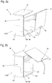
- Fig. 1 shows an isometric view of an upper cabinet, for example a kitchen, as a first embodiment of a piece of furniture with furniture walls made from a building board according to the application.
- the upper cabinet comprises a furniture body 10 with a lower shelf 11 and a top shelf 12 as well as two side walls 13.
- a rear wall is preferably provided for reasons of stability, among other things, but is not shown in this exemplary embodiment.
- the furniture body 10 is open to the front in order to gain access to the interior of the cabinet.
- a flap arrangement 20 with a one-piece flap 21 is provided in order to be able to close the opening of the furniture body 10.
- the one-piece flap 21 is pivotably mounted along its upper horizontal side edge.
- fittings 30 are provided which are connected to the one-piece flap 21 by means of a lever mechanism 31 in the upper region thereof.
- the fittings 30 are arranged within the respective side wall 13 (with the exception of the lever mechanism 31 extended in the illustrated open position). In the closed state of the flap 21, the lever mechanism 31 is completely retracted into the side wall 13 except for the assembly elements for connection to the flap 21.
- the area within the side wall 13 in which the fitting 30 is located is in the Fig. 1 indicated by a dashed line.
- the side wall 13 is characterized by side surfaces 131 which are ideally in one piece and can have a consistently identical surface quality over the entire surface.
- the surface of the one-piece side faces 131 can produce design effects by means of different patterns, surface properties or different colors. This preferably applies both to an outer of the side surfaces 131 and to an inner of the side surfaces 131 facing the interior of the furniture body 10.
- the side walls 13 also have an end face 132 which has an opening 133 in the area of the fitting 30 into which the Lever mechanism 31 of the fitting 30 is immersed or from which the lever mechanism 31 extends. In the closed state of the flap arrangement 20, the lever mechanism 31 is completely immersed in the opening 133 apart from any fastening means with which it is connected to the one-piece flap 21 here.
- the end face 132 is provided with a narrow-side coating 134, which can be designed as edge banding 134.
- the side walls 13 are made of building panels 40 that are used in connection with the Figures 5ff . are explained in more detail.
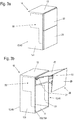
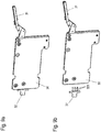
- FIG. 2a and 2b Another wall cabinet is shown as an example of a piece of furniture with a side wall according to the application, each in an isometric view.
- a one-piece flap 21 is provided as a flap arrangement 20 in order to close a furniture body 10 towards the front.
- the two Figures 2a and 2b differ in the opening state of the flap arrangement 20.
- Fig. 2a shows a partially open state of the flap arrangement 20, where to Figure 2b the maximum opening state of the flap arrangement 20 reproduces.
- a lifting and swiveling fitting is provided which enables a combined swiveling and sliding movement of the one-piece flap 21.
- the in Figure 2b In the in Figure 2b In the fully open position shown, at least a part of the flap 21 is positioned above the top panel 12 of the furniture body 10.
- the flap 21 is easily accessible in the open position in order to be able to close it again.
- the side walls 13 are made from building panels 40 which the fitting 30 has already been added to.
- FIG. 3a shows the flap assembly 20 in a closed and Figure 3b in an open position.
- a two-part flap arrangement 20 which has an upper flap part 22 and a lower flap part 23.
- the side walls 13 are made of building panels 40 which receive a fitting 30.
- This is coupled with lever works 31 both with the upper flap part 22 and with the lower flap part 23.
- additional hinges 25 are provided which couple the upper and lower flap parts 22, 23 with one another in a pivotable manner along their connecting line. Depending on the design of the flap fitting, the hinges can also be omitted.
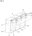
- Fig. 4 shows a further upper cabinet with furniture body 10 and flap arrangement 20, in which fittings 30 for guiding the flap arrangement 20 in a building board 40 according to the application are arranged.
- the furniture body 10 has an interior space divided by vertical partitions 14.
- two partition walls 14 are provided, which divide the interior space into three sections.
- each partition 14 is made from a building board 40.
- the arrangement shown can, however, also be implemented with only one partition wall or more than the two partition walls 14 shown.
- the flap arrangement 20 is in two parts with an upper flap part 22 and a lower flap part 23.
- the width of the flap arrangement 20 and also the upper and lower flap parts 22, 23 extends over the entire furniture body 10.
- the present fittings 30 are also arranged in the partition walls 14. Both the side walls 13 and the partition walls 14 are made from building boards 40 according to the application.
- the building boards are characterized by continuous side surfaces with a surface look and feel that are uniform over the entire surface. In particular, no transition in the area of the edge of the fitting 30 can be seen in the surface.
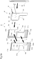
- FIG Figure 5a A first embodiment of a building board 40 with which this is achieved is shown in FIG Figure 5a shown in an exploded isometric drawing.
- the construction panel 40 shown can be used, for example, as a side wall 13 in the exemplary embodiments of FIG Figures 1-4 be used and also as a partition 14 in the embodiment of Fig. 4 .
- the building board 40 comprises two basic elements, which are mirror-inverted here and each have a plate-shaped core half 41a, 41b, both of which are provided with a recess 42a and 42b, respectively. After a later assembly, the two core halves 41a, 41b together form a core 41 of the building board 40.
- the recesses 42a and 42b can also be designed differently. The shape of the recesses 42a or 42b depends on the fitting to be used and its external geometry.
- the core halves 41a, 41b are made, for example, from a chipboard or a medium or high density fiberboard (MDF - Medium Density Fiberboard or HDF - High Density Fiberboard).
- the core halves 41a, 41b each have a rectangular oversize of the size that will later have the side or partition in the furniture body to be manufactured (see, for example, side wall 13 of the furniture body 10 according to the exemplary embodiments of FIG Figures 1-4 ).
- each of the core halves 41a, 41b a large flat recess 42a, 42b is made, which is open to a first end face 411a, 411b. Only in the upper and / or lower area of the core halves 41a, 41b does a narrow section of the end face 411a, 411b remain on this side.
- the recesses 42a, 42b can be designed mirror-symmetrically. In the area in between, the edge of the recess 42a, 42b now forms an inwardly offset end face 415a, 415b following the contour of the recess 42a, 42b.
- the first end face 411a or 411b is also referred to below as the front end face 411a, 411b.
- each core half 41a, 41b, one in the Figure 5a respective lower left end face 412a, 412b, a rear end face 413a, 413b and an upper end face 414a, 414b run straight in accordance with the rectangular allowance.
- core halves 41a, 41b are equally thick in the example shown, the term “core halves” also includes core halves 41a, 41b of different thicknesses in the context of the application.
- the recesses 42a, 42b correspond in their contour to the outer contour of a fitting 30 to be used, here an approximately L-shaped contour.
- the recesses 42a, 42b can be made in the core halves 41a, 41b, for example, by milling each with the symbolically illustrated milling tools 1.
- Other machining techniques such as drilling in connection with (plunge) saw cuts can also be used to produce the recesses 42a, 42b.
- an archetype process e.g. in accordance with the DIN 8580 standard
- the recess can also be pressed during the production of the plate.
- the milling can take place through the entire thickness of the respective core half 41a, 41b.
- provision can also be made for a thin wall of the material of the core halves 41a or 41b to stand in the area of the recess 42a or 42b.
- machining can be carried out from one of the side surfaces of the respective core halves 41a, 41b. Machining only from the first end face 411a or 411b is not necessary in the case of the core halves 41a, 41b.
- the recess can easily assume any depth (viewed from the original end faces 411a, 411b) and is also suitable for receiving fittings 30 with a large installation depth.
- shapes such as undercuts can be created that are not possible when machining a plate on the front.
- the core halves 41a, 41b form a core 41, in which the recesses 42a, 42b complement each other to form a recess 42 which receives the fitting 30.
- a cover layer 43a or 43b is applied, for example laminated, in a mirror-inverted manner to the core halves 41a, 41b. This can be done either before or after making the recesses 42a, 42b.
- These cover layers 43a, 43b are preferably already provided with a decorative surface. Their thickness ranges from a few tenths of a mm (millimeters) to about 2 or 3 mm.
- Typical plastic-based coating materials, lacquered paper layers, veneers or cork can be used as cover layers 43a, 43b.
- Leather or fabrics can also be used.
- the cover layers 43a, 43b can also be omitted.
- the core halves 41a, 41b can be, for example, for the production of a standard furniture wall with a thickness of 16 mm in a simple manner by means of two completely 8 mm panels, possibly already provided with the cover layers 43a, 43b on both sides, with the recesses 42a, 42b can be introduced into the core halves.
- the two panels can also already be provided with a narrow-side coating such as an edge band on the front sides.
- the recesses 42a, 42b ideally have a bottom made of the material of the core halves 41a, 41b, so that the adjoining cover layers 43a, 43b are not damaged.
- the edge band on the front face 411a, 411b can be milled back.
- the core halves 41a, 41b can be glued, with the core halves 41a, 41b in this embodiment also having a cover layer in the parting line if the starting material of the core halves 41a, 41b is already coated on both sides.
- the fitting 30 can also be glued to the back-milled edge band.
- the edge banding can also be applied subsequently if the fitting 30 has already been inserted into the recess 42.
- the narrow side coating or the edge banding covers the front housing wall of the fitting so that it is covered.
- the fitting 30 can, for example, be guided between the two core halves 41a, 41b in a first assembly step I and both core halves 41a, 41b can be closed around the fitting 30 in the manner of a shell and connected to one another in a second assembly step II.
- the narrow side coating or the edge banding 134 is applied to the end face 411a, 411b.
- the fitting 30 can first be inserted into one of the recesses, for example the recess 42b of the core half 41b. Then the second basic element, that is to say the core half 41a with the cover layer 43a and the recess 42a, is slipped over the fitting 30 and the two core halves 41a, 41b are joined together and connected to one another.
- the second basic element that is to say the core half 41a with the cover layer 43a and the recess 42a
- connection of the fitting 30 with the core halves 41a, 41b or the cover layers 43a, 43b is described in connection with Figure 5b described in more detail.
- the in Figure 5a shown embodiment is in the area of the respective end face 414a, 414b of the core halves 41a, 41b on the edge of the recesses 42a, 42b in sections the respective core half 41a, 41b adjacent to the end face 415a or 415b on the side facing away from the cover layer 43a, 43b milled off so that that shoulder surfaces 416a and 416b are formed which form a shoulder with respect to the remaining side surfaces of the core halves 41a, 41b.
- the fitting 30 has two side plates 301 spaced apart from one another, which laterally delimit the fitting 30 and provide the pivot points for the lever mechanism 31.
- Spacer sleeves or bolts which connect the side plates 301 to one another and fix them parallel to one another at a defined distance, can be arranged between the side plates 301.
- screw elements can also serve as spacers, which offer the possibility of at least slightly varying the distance between the side plates 301 and thereby adapting it to the thickness of the core 41.
- tabs 302 protrude outward beyond the side plates 301 on different sides.
- the tabs 302 can be designed, for example, as a fold of correspondingly beveled side plates 301.
- the tabs 302 are arranged in a plane in the center of the side plates 301.
- staples 303 projecting transversely to the tabs 302 are arranged, for example formed from the exposed material of the tabs 302.
- Figure 5b shows a section of the building board 40 of FIG Figure 5a in an assembled state in a schematic section in the area of the edge of the inserted fitting 30.
- the tabs 302 in the Area of the shoulder surfaces 416a and 416b are defined between the core halves 41a, 41b connected to one another.
- the staples 303 are pressed into the material of the core halves 41a, 41b on both sides and thus fasten the fitting 30 in the building board 40 to the core halves 41a, 41b.
- the core halves 41a, 41b are also connected to one another in this way via the staples 303 and the tabs 302.
- the side plate 301 of the fitting 30 can also be glued flat to the bottom of the recess 42a, 42b of the core half 41a, 41b.
- the fitting 30 and the core 41 formed from the two core halves 41a and 41b preferably have the same thickness.
- the same thickness is preferably in a range from 6 mm to about 10 mm.
- the core 41 and the fitting 30 thus form a unit in which the fitting 30 is flush with the surface of the core 41 on both sides. Furthermore, the front edges of the fitting 30 also run flush with the two remaining sections of the actual first end faces 411a, 411b of the core 41.
- a narrow-side coating 134 which can be designed as an edge banding 134, is applied to the end faces 411a, 411b and the front edges of the fitting 30.
- the end face of the building panel 40 is homogeneously covered by the edge banding, so that the side panels 301 or the outer wall of the housing of the fitting 30 are covered.
- FIG. 11 shows a detail of a front view of an end face 132 of the building board 40 of FIG Figure 5a with inserted fitting.
- An edge banding 134 is applied to the end face 132 and covers both the end face 411 of the core and the side plates 301 or the housing outer wall of the fitting 30.
- the housing wall hidden behind the edging is shown here with dashed lines.
- the lever mechanism 31 of the fitting can move freely through an opening in the edge band 133.
- the narrow-side coating or the edge banding 134 is applied after the fitting has been installed in the recesses 42.
- the edge band 134 can also be applied beforehand to the end face 411a, 411b of the core halves 41a, 41b. In this case the edge trim 134 is milled back and glued to the front housing outer wall when the fitting 30 is inserted.
- the structural element 40 is produced, from which a side wall or an intermediate wall, for example, which already contains the fitting 30, can be manufactured in a simple manner during the manufacture of a furniture body.
- the building board 40 has a machinable section, within which the building board 40 is in the manufacturing process of the Furniture body can be shortened, for example, can be sawed off, or can be milled into the profiles or assembly elements can be attached.
- a machinable section 412a 'or 412b' is provided - for example only on the lower end face 412a, b - within which the building board can be processed without the fitting 30 being damaged and without the building board 40 and in particular the fastening of the fitting 30 loses stability.
- the protruding machinable section 412a ', b' which is indicated in the figure by hatching, can also accommodate fastening elements, for example for elements for organizing the interior of the furniture, or further fittings can be fastened if necessary.
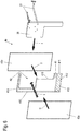
- Fig. 6 shows an isometric exploded view of an alternative structure of a building board 40 and illustrates its production.
- the building board 40 has a core 41, again manufactured, for example, from a chipboard or MDF or HDF board.
- a recess 42 for the fitting 30 is made in the core 41, for example milled in from one of the side surfaces.
- the recess 42 is open towards a first end face 411 of the core 41, so that the lever mechanism 31 of the fitting can dip into the building board 40.
- the core 41 is in one piece and only adjoins below the fitting 30.
- the core 41 and the fitting 30 can be connected to one another via connecting elements not shown here, for example screws, clamps, pins, staples or the like.
- An adhesive connection can also be provided in addition to the connection elements mentioned or as the only connection.
- Cover layers 43a, 43b are applied, in particular glued or laminated on, from each side to the arrangement made up of the core 41 and the fitting 30, which may be connected to it.
- the fitting 30 is selected with regard to its material and the material thickness, for example of the side plates of the fitting 30, so that it is not pressed in even during a lamination process, which could lead to an unevenness of the surface of the cover layers 43a, 43b. Smaller unevennesses in the side plates of the fitting 30 are compensated for by the cover layers 43a, 43b or by the adhesive layer located between the cover layer 43a, 43b and the fitting 30. Such minor unevenness can arise, for example, from the bearing points of bolts which serve to pivot the lever mechanism 31 in the fitting 30.
- FIG. 6 The symbolized manufacturing process of the building board 40, in which the core 41 and the fitting 30 are initially aligned with one another and optionally connected to one another and then merged with the cover layers 43a, b to form the building board 40, enables the use of a fitting 30, which is as shown for example, extends over the entire width of the building board 40. In this way, larger and more complex fittings 30 can also be used in the building board 40 than would be possible in a pocket of a side wall milled out at the end.
- a machinable section 412 ' is provided as an overhang, within which the building board 40 can be processed or within which further elements can be mounted.
- the narrow side coating provided for the end face 411 is, for example, an edge band.
- the edge band covers the end face of the core 41 and the end face of the outer wall of the fitting 30.
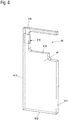
- Fig. 7 shows a further embodiment of a building board 40 with a core 41 and an integrated fitting 30.
- a two-part flap with sections 22, 23 is mounted on the fitting 30.
- an outer cover layer is shown as transparent in order to show the inner structure of the building board 40.
- the core 41 of the building board 40 does not consist of a homogeneous material, but is designed as a composite material. In the edge areas, this core 41 is still made of a compacted material, for example a chipboard, an HDF or an MDF board. In an inner region, in particular in the lower part of the core 41, in which the fitting 30 is made narrower, a light honeycomb structure material 417, for example a cardboard material, is provided. By using the honeycomb structure material 417, the weight of the building panel 40 and also the material cost can be reduced. In particular in connection with the attached and preferably glued-on cover layers 43a, 43b, sufficient stability of the building board 40 is nevertheless achieved.
- the building board 40 shown again has protruding machinable sections 412 ', 413' and 414 'as processing zones, in this example on three end faces 412, 413 and 414, ie on all end faces except the first end face 411 into which the fitting 30 is inserted .
- the processing zones are sufficiently spaced from the fitting 30 so that the stability of the building board 40 is not impaired.
- an assembly zone that extends somewhat further to the fitting 30 can be marked, within which assembly elements, for example connecting elements to further walls of the furniture body, can be attached to the building board 40.
- dashed cutting lines 2 are indicated by way of example, along which the building board 40 can be cut to length during the manufacture of a furniture body.
- the prefabricated building board 40 with already integrated fitting 30 can thus be used in order to produce a piece of furniture with a wall-integrated fitting with little effort.
- electrical lines and also further electrical components can also be integrated into the building board 40 for electrification of the piece of furniture.
- lighting equipment such as LED lights is also possible.
- the size of the protruding machinable sections 412 ', 413' and 414 'or their edges can preferably be indicated on the building board 40 in order to prevent machining in an area in which the machining could lead to damage to the fitting 30 or the
- the integrity or stability of the building plate 40 is influenced.
- An advantageous way of specifying the edges of the protruding machinable sections 412 ', 413' and 414 ' is to print the edges on a removable protective film with which the cover layers 43a, b are also protected during further processing.
- the position and dimensions of an integrated fitting 30 can also be specified in this way. Processing areas for fastening means for interior organizations and / or furniture connection areas can also be drawn in on the protective film. These areas can also lie in a surface area that cannot be sawn off.
- information about the building board 40 and / or its workability can be integrated into the building board 40 in the form of a readable data carrier.
- an RFID (Radio Frequency IDentification) transponder can be inserted into the building board 40, preferably below one of the cover layers 43a, b. If necessary, the position of the RFID transponder can be indicated on the outside of the building board 40, e.g. again on the protective film mentioned.
- the RFID transponder can contain e.g. an article number, the year of construction, a batch, color information, dimensions and position of the fitting, type and load-bearing capacity of the fitting, etc. as data that can be read out wirelessly via a reader.
- a reader e.g. a reader that can be read out wirelessly via a reader.
- the furniture manufacturer it can be ensured, for example, directly on a processing machine, that the correct type of building board is supplied for a piece of furniture to be manufactured.
- a wall hanger is provided, preferably on the rear end face 413 of the building board 40, with which the piece of furniture can be hung on a building wall.
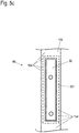
- Fig. 8 shows a core 41 for a building board 40, which is prepared for receiving a wall hanger.
- the core 41 has a receiving channel 418 pointing from the recess 42 to the rear end face 413, into which the wall hanger can be inserted.
- a further channel 419 is introduced into the core 41, which extends into the receiving channel 418.
- adjusters of an inserted wall hanger for example for height and / or inclination adjustment, can be achieved with the aid of a tool in order to be able to adjust a piece of furniture suspended on a building wall.
- the receiving channel 418 can extend into the end face 415 of the recess 42. In this way, the wall hanger can be connected directly to the fitting 30.
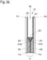
- Figure 9a is a in the core 41 of the Fig. 8 insertable fitting 30 shown in an isometric view.
- a wall hanger 32 is mounted, which when the fitting 30 is inserted into the core 41 according to FIG Fig. 8 protrudes into the receiving channel 418. It can be provided that the wall hanger 32 is placed on a screw head or hook of a screw screwed into the building wall.
- Figure 9b shows the wall hanger 32 before it is mounted on the fitting 30.
- the wall hanger 32 has connecting means with which it can be mounted on the fitting 30 with as little tools as possible.
- connecting pins 321 are provided as connecting means, which snap into corresponding receptacles in the fitting 30 when the wall hanger 32 is inserted into the fitting 30.
- the wall hanger 32 can, if necessary, be inserted from the outside into the receiving channel 418 of a building board 40 in the fitting 30.
- a wall hanger of the building board 40 could also be attached to the core 41.
- a large-area force distribution from the wall hanger 32 to the core 41 is advantageously achieved and local forces acting on the material of the core 41 are prevented from exceeding the tensile strength of the (wood) material of the core 41 .
- forces that act on the fitting 30, for example the weight and lever forces of a door guided by the fitting 30 or Flap effectively derived directly from the wall hanger 32 onto the building wall.
Landscapes
- Engineering & Computer Science (AREA)
- Mechanical Engineering (AREA)
- Connection Of Plates (AREA)
- Cabinets, Racks, Or The Like Of Rigid Construction (AREA)
- Combinations Of Kitchen Furniture (AREA)
Priority Applications (1)
| Application Number | Priority Date | Filing Date | Title |
|---|---|---|---|
| PL18714132T PL3589166T3 (pl) | 2017-02-28 | 2018-02-23 | Płyta konstrukcyjna dla ściany meblowej oraz sposób wytwarzania takiej płyty konstrukcyjnej oraz ściany meblowej |
Applications Claiming Priority (2)
| Application Number | Priority Date | Filing Date | Title |
|---|---|---|---|
| DE102017104185.0A DE102017104185A1 (de) | 2017-02-28 | 2017-02-28 | Bauplatte für eine Möbelwand, Verfahren zur Herstellung einer solchen Bauplatte und einer Möbelwand sowie Möbelkorpus oder Möbel mit einer Möbelwand |
| PCT/EP2018/054528 WO2018158151A2 (de) | 2017-02-28 | 2018-02-23 | Bauplatte für eine möbelwand, verfahren zur herstellung einer solchen bauplatte und einer möbelwand sowie möbelkorpus oder möbel mit einer möbelwand |
Publications (2)
| Publication Number | Publication Date |
|---|---|
| EP3589166A2 EP3589166A2 (de) | 2020-01-08 |
| EP3589166B1 true EP3589166B1 (de) | 2021-05-05 |
Family
ID=61827671
Family Applications (1)
| Application Number | Title | Priority Date | Filing Date |
|---|---|---|---|
| EP18714132.0A Active EP3589166B1 (de) | 2017-02-28 | 2018-02-23 | Bauplatte für eine möbelwand und verfahren zur herstellung einer solchen bauplatte und einer möbelwand |
Country Status (8)
| Country | Link |
|---|---|
| US (1) | US11350747B2 (pl) |
| EP (1) | EP3589166B1 (pl) |
| JP (1) | JP7189880B2 (pl) |
| CN (1) | CN110520016B (pl) |
| DE (1) | DE102017104185A1 (pl) |
| ES (1) | ES2880325T3 (pl) |
| PL (1) | PL3589166T3 (pl) |
| WO (1) | WO2018158151A2 (pl) |
Families Citing this family (12)
| Publication number | Priority date | Publication date | Assignee | Title |
|---|---|---|---|---|
| DE102015113427A1 (de) * | 2015-08-14 | 2017-02-16 | Form Orange Produktentwicklung | Wandschrank, insbesondere Küchen-Wandschrank |
| DE102017104182A1 (de) * | 2017-02-28 | 2018-08-30 | ambigence GmbH & Co. KG | Möbel |
| DE102018119539A1 (de) * | 2018-08-10 | 2020-02-13 | ambigence GmbH & Co. KG | Wand für ein Möbel, Verfahren zur Herstellung einer solchen Wand und Möbelkorpus oder Möbel mit einer solchen Wand |
| AT521965B1 (de) * | 2019-02-15 | 2020-07-15 | Blum Gmbh Julius | Möbelscharnier |
| DE102019112993A1 (de) * | 2019-05-16 | 2020-11-19 | Hettich-Oni Gmbh & Co. Kg | Montagekassette für einen Bewegungsbeschlag sowie Möbelplatte mit integrierter Montagekassette und Möbel oder Möbelkorpus mit einer derartigen Möbelplatte |
| AT522656B1 (de) * | 2019-05-17 | 2025-04-15 | Blum Gmbh Julius | Möbelantrieb |
| DE102019118322A1 (de) * | 2019-07-05 | 2021-01-07 | ambigence GmbH & Co. KG | Möbelkomponente |
| DE102019119295B3 (de) * | 2019-07-16 | 2021-01-21 | ambigence GmbH & Co. KG | Möbelkomponente |
| AT524025B1 (de) * | 2020-09-14 | 2022-02-15 | Blum Gmbh Julius | Wand für einen Möbelkorpus und Verfahren zu deren Herstellung |
| AT524339B1 (de) | 2020-10-22 | 2023-10-15 | Blum Gmbh Julius | Möbelantrieb zum Bewegen einer Möbelfront |
| US11618571B2 (en) * | 2020-12-21 | 2023-04-04 | B/E Aerospace, Inc. | Bi-fold compartment door with spring assist and cam latch |
| AT525449B1 (de) * | 2021-12-03 | 2023-04-15 | Blum Gmbh Julius | Wand und Verfahren zum Herstellen einer Wand für einen Möbelkorpus |
Family Cites Families (24)
| Publication number | Priority date | Publication date | Assignee | Title |
|---|---|---|---|---|
| DE1559963A1 (de) | 1966-12-21 | 1969-12-18 | Ernst Maurmann Kg | Scharnier fuer Tueren bzw. Klappen u.dgl.,vorzugsweise an Moebeln |
| DE2148268C2 (de) * | 1971-09-28 | 1982-05-13 | Schaffitzel Möbelwerk KG, 7170 Schwäbisch Hall | Möbeltür mit zwei wahlweise benutzbaren Schwenkachsen |
| DE2723850C2 (de) | 1977-05-26 | 1986-08-28 | Richard Heinze GmbH & Co KG, 4905 Spenge | Möbelscharnier |
| US4365454A (en) * | 1979-02-21 | 1982-12-28 | Cubit Corporation | Construction system |
| JPS57112818A (en) | 1980-09-30 | 1982-07-14 | Eidai Co Ltd | Constitutional material of furniture |
| ES2191991T3 (es) | 1998-03-18 | 2003-09-16 | Wilhelm Riesmeier | Procedimiento para la fabricacion de estructuras de muebles. |
| JP2000157362A (ja) | 1998-11-30 | 2000-06-13 | Inax Corp | キャビネット・カウンターブラケットの設置構造 |
| WO2006136085A1 (en) * | 2005-06-20 | 2006-12-28 | Luhao Leng | Composite plate cabinet |
| DE102006007702B4 (de) * | 2006-02-13 | 2009-04-23 | Hetal-Werke Franz Hettich Gmbh & Co. Kg | Beschlagvorrichtung für eine Möbelklappe |
| AT503418B1 (de) | 2006-03-28 | 2007-10-15 | Blum Gmbh Julius | Schublade mit wenigstens einer hölzernen schubladenseitenwand |
| CN102159378B (zh) | 2008-07-21 | 2013-11-13 | 卡尔瓦特尼曼有限两合公司 | 在特别是板状工件的窄面施用边缘条获得的工件及其方法 |
| DE202009004805U1 (de) | 2009-05-12 | 2010-09-23 | Hettich Holding Gmbh & Co. Ohg | Möbelwand und Möbel |
| DE202009004806U1 (de) | 2009-05-12 | 2010-10-14 | Hettich Holding Gmbh & Co. Ohg | Möbel |
| DE202013003189U1 (de) | 2013-04-08 | 2014-07-10 | Grass Gmbh & Co. Kg | Wandelement für einen Möbelkorpus mit einer Korpuswand |
| TWI592117B (zh) * | 2014-06-06 | 2017-07-21 | Kuangyi Chen | Cabinets with concealed wall holes side panel structure |
| FR3023331B1 (fr) | 2014-07-01 | 2017-03-10 | Ludovic Charlemagne | Systeme d'attaches multifonction et mobilier le comprenant |
| DE102015113427A1 (de) | 2015-08-14 | 2017-02-16 | Form Orange Produktentwicklung | Wandschrank, insbesondere Küchen-Wandschrank |
| DE202016100187U1 (de) | 2016-01-15 | 2017-04-20 | Siegfried und André Schelbach L GbR (vertretungsberechtigte Gesellschafter: Siegfried und André Schelbach, 32758 Detmold) | Möbelplatte |
| CN105507493A (zh) * | 2016-01-21 | 2016-04-20 | 李涛 | 一种带身份识别的板材及其制造工艺 |
| DE102017104183A1 (de) * | 2017-02-28 | 2018-08-30 | ambigence GmbH & Co. KG | Möbel und Wandelement für ein Möbel |
| DE102017104170A1 (de) * | 2017-02-28 | 2018-08-30 | ambigence GmbH & Co. KG | Wand eines Möbelkorpus, Verfahren zur Herstellung einer solchen Wand und Möbelkorpus oder Möbel mit einer solchen Wand |
| DE102017104184A1 (de) * | 2017-02-28 | 2018-08-30 | ambigence GmbH & Co. KG | Wand eines Möbelkorpus und Möbelkorpus oder Möbel mit einer solchen Wand |
| DE102017104169A1 (de) * | 2017-02-28 | 2018-08-30 | ambigence GmbH & Co. KG | Wand eines Möbelkorpus, Verfahren zur Herstellung einer solchen Wand und Möbelkorpus oder Möbel mit einer solchen Wand |
| DE202017101255U1 (de) * | 2017-03-06 | 2018-03-07 | Flap Competence Center Kft | Klappenbeschlaganordnung und Klappenbeschlag |
-
2017
- 2017-02-28 DE DE102017104185.0A patent/DE102017104185A1/de not_active Withdrawn
-
2018
- 2018-02-23 ES ES18714132T patent/ES2880325T3/es active Active
- 2018-02-23 EP EP18714132.0A patent/EP3589166B1/de active Active
- 2018-02-23 WO PCT/EP2018/054528 patent/WO2018158151A2/de not_active Ceased
- 2018-02-23 CN CN201880014638.7A patent/CN110520016B/zh active Active
- 2018-02-23 JP JP2019547418A patent/JP7189880B2/ja active Active
- 2018-02-23 PL PL18714132T patent/PL3589166T3/pl unknown
- 2018-02-23 US US16/489,180 patent/US11350747B2/en active Active
Also Published As
| Publication number | Publication date |
|---|---|
| EP3589166A2 (de) | 2020-01-08 |
| PL3589166T3 (pl) | 2021-10-25 |
| US20190380496A1 (en) | 2019-12-19 |
| WO2018158151A2 (de) | 2018-09-07 |
| JP7189880B2 (ja) | 2022-12-14 |
| CN110520016A (zh) | 2019-11-29 |
| US11350747B2 (en) | 2022-06-07 |
| DE102017104185A1 (de) | 2018-08-30 |
| WO2018158151A3 (de) | 2018-11-01 |
| JP2020508779A (ja) | 2020-03-26 |
| ES2880325T3 (es) | 2021-11-24 |
| CN110520016B (zh) | 2022-03-04 |
Similar Documents
| Publication | Publication Date | Title |
|---|---|---|
| EP3589166B1 (de) | Bauplatte für eine möbelwand und verfahren zur herstellung einer solchen bauplatte und einer möbelwand | |
| EP3589164B1 (de) | Wand eines möbelkorpus, verfahren zur herstellung einer solchen wand und möbelkorpus oder möbel mit einer solchen wand | |
| EP3589163B1 (de) | Wand eines möbelkorpus, verfahren zur herstellung einer solchen wand und möbelkorpus oder möbel mit einer solchen wand | |
| EP3589165B1 (de) | Wand für einen möbelkorpus, verfahren zur herstellung einer solchen wand und möbelkorpus oder möbel mit einer solchen wand | |
| EP3589161B1 (de) | Möbel und wandelement für ein möbel | |
| EP3589811B1 (de) | Möbel mit aufsetzbarem platteförmigem verbundelement mit integriertem beschlag | |
| EP3589160B1 (de) | Wand eines möbelkorpus und möbelkorpus oder möbel mit einer solchen wand | |
| EP3735152B1 (de) | Anordnung einer möbelplatte und eines bewegungsbeschlages mit integriertem montageelement für den bewegungsbeschlag, möbelkörper und möbel, die eine solche möbelplatte enthalten | |
| DE102012008520A1 (de) | Leichtbauplatte, Verbindungsanordnung und Verfahren zum Herstellen einer Verbindungsanordnung | |
| DE102018120661A1 (de) | Möbelkomponente und Verfahren zur Herstellung | |
| EP3589162B1 (de) | Möbel mit äusserem aufsatzelement mit integriertem beschlag | |
| EP3833222B1 (de) | Verfahren zur herstellung einer wand für ein möbel | |
| DE4127636A1 (de) | Tuerblatt, verfahren zur herstellung eines tuerblatts und bausatz fuer ein tuerblatt | |
| WO2018158156A1 (de) | Wand eines möbelkorpus und möbelkorpus oder möbel mit einer solchen wand | |
| DE102017104176B4 (de) | Möbelkorpus und Möbel | |
| AT524025B1 (de) | Wand für einen Möbelkorpus und Verfahren zu deren Herstellung | |
| DE102017104186A1 (de) | Wandeinbaumöbel | |
| DE29503724U1 (de) | Möbelbauteil, insbesondere für Reisemobile und Caravans | |
| DE20208108U1 (de) | Schrank |
Legal Events
| Date | Code | Title | Description |
|---|---|---|---|
| STAA | Information on the status of an ep patent application or granted ep patent |
Free format text: STATUS: UNKNOWN |
|
| STAA | Information on the status of an ep patent application or granted ep patent |
Free format text: STATUS: THE INTERNATIONAL PUBLICATION HAS BEEN MADE |
|
| PUAI | Public reference made under article 153(3) epc to a published international application that has entered the european phase |
Free format text: ORIGINAL CODE: 0009012 |
|
| STAA | Information on the status of an ep patent application or granted ep patent |
Free format text: STATUS: REQUEST FOR EXAMINATION WAS MADE |
|
| 17P | Request for examination filed |
Effective date: 20190923 |
|
| AK | Designated contracting states |
Kind code of ref document: A2 Designated state(s): AL AT BE BG CH CY CZ DE DK EE ES FI FR GB GR HR HU IE IS IT LI LT LU LV MC MK MT NL NO PL PT RO RS SE SI SK SM TR |
|
| AX | Request for extension of the european patent |
Extension state: BA ME |
|
| DAV | Request for validation of the european patent (deleted) | ||
| DAX | Request for extension of the european patent (deleted) | ||
| GRAP | Despatch of communication of intention to grant a patent |
Free format text: ORIGINAL CODE: EPIDOSNIGR1 |
|
| STAA | Information on the status of an ep patent application or granted ep patent |
Free format text: STATUS: GRANT OF PATENT IS INTENDED |
|
| RIC1 | Information provided on ipc code assigned before grant |
Ipc: A47B 96/20 20060101AFI20200908BHEP Ipc: E05D 3/16 20060101ALI20200908BHEP Ipc: E05D 15/46 20060101ALI20200908BHEP Ipc: E05D 15/26 20060101ALI20200908BHEP |
|
| INTG | Intention to grant announced |
Effective date: 20201005 |
|
| GRAJ | Information related to disapproval of communication of intention to grant by the applicant or resumption of examination proceedings by the epo deleted |
Free format text: ORIGINAL CODE: EPIDOSDIGR1 |
|
| STAA | Information on the status of an ep patent application or granted ep patent |
Free format text: STATUS: REQUEST FOR EXAMINATION WAS MADE |
|
| GRAS | Grant fee paid |
Free format text: ORIGINAL CODE: EPIDOSNIGR3 |
|
| STAA | Information on the status of an ep patent application or granted ep patent |
Free format text: STATUS: GRANT OF PATENT IS INTENDED |
|
| GRAP | Despatch of communication of intention to grant a patent |
Free format text: ORIGINAL CODE: EPIDOSNIGR1 |
|
| INTC | Intention to grant announced (deleted) | ||
| GRAA | (expected) grant |
Free format text: ORIGINAL CODE: 0009210 |
|
| STAA | Information on the status of an ep patent application or granted ep patent |
Free format text: STATUS: THE PATENT HAS BEEN GRANTED |
|
| INTG | Intention to grant announced |
Effective date: 20210310 |
|
| AK | Designated contracting states |
Kind code of ref document: B1 Designated state(s): AL AT BE BG CH CY CZ DE DK EE ES FI FR GB GR HR HU IE IS IT LI LT LU LV MC MK MT NL NO PL PT RO RS SE SI SK SM TR |
|
| REG | Reference to a national code |
Ref country code: GB Ref legal event code: FG4D Free format text: NOT ENGLISH |
|
| REG | Reference to a national code |
Ref country code: CH Ref legal event code: EP |
|
| REG | Reference to a national code |
Ref country code: AT Ref legal event code: REF Ref document number: 1388736 Country of ref document: AT Kind code of ref document: T Effective date: 20210515 |
|
| REG | Reference to a national code |
Ref country code: DE Ref legal event code: R096 Ref document number: 502018005151 Country of ref document: DE |
|
| REG | Reference to a national code |
Ref country code: IE Ref legal event code: FG4D Free format text: LANGUAGE OF EP DOCUMENT: GERMAN |
|
| REG | Reference to a national code |
Ref country code: LT Ref legal event code: MG9D |
|
| PG25 | Lapsed in a contracting state [announced via postgrant information from national office to epo] |
Ref country code: BG Free format text: LAPSE BECAUSE OF FAILURE TO SUBMIT A TRANSLATION OF THE DESCRIPTION OR TO PAY THE FEE WITHIN THE PRESCRIBED TIME-LIMIT Effective date: 20210805 Ref country code: FI Free format text: LAPSE BECAUSE OF FAILURE TO SUBMIT A TRANSLATION OF THE DESCRIPTION OR TO PAY THE FEE WITHIN THE PRESCRIBED TIME-LIMIT Effective date: 20210505 Ref country code: HR Free format text: LAPSE BECAUSE OF FAILURE TO SUBMIT A TRANSLATION OF THE DESCRIPTION OR TO PAY THE FEE WITHIN THE PRESCRIBED TIME-LIMIT Effective date: 20210505 Ref country code: LT Free format text: LAPSE BECAUSE OF FAILURE TO SUBMIT A TRANSLATION OF THE DESCRIPTION OR TO PAY THE FEE WITHIN THE PRESCRIBED TIME-LIMIT Effective date: 20210505 |
|
| REG | Reference to a national code |
Ref country code: ES Ref legal event code: FG2A Ref document number: 2880325 Country of ref document: ES Kind code of ref document: T3 Effective date: 20211124 |
|
| PG25 | Lapsed in a contracting state [announced via postgrant information from national office to epo] |
Ref country code: NO Free format text: LAPSE BECAUSE OF FAILURE TO SUBMIT A TRANSLATION OF THE DESCRIPTION OR TO PAY THE FEE WITHIN THE PRESCRIBED TIME-LIMIT Effective date: 20210805 Ref country code: LV Free format text: LAPSE BECAUSE OF FAILURE TO SUBMIT A TRANSLATION OF THE DESCRIPTION OR TO PAY THE FEE WITHIN THE PRESCRIBED TIME-LIMIT Effective date: 20210505 Ref country code: PT Free format text: LAPSE BECAUSE OF FAILURE TO SUBMIT A TRANSLATION OF THE DESCRIPTION OR TO PAY THE FEE WITHIN THE PRESCRIBED TIME-LIMIT Effective date: 20210906 Ref country code: RS Free format text: LAPSE BECAUSE OF FAILURE TO SUBMIT A TRANSLATION OF THE DESCRIPTION OR TO PAY THE FEE WITHIN THE PRESCRIBED TIME-LIMIT Effective date: 20210505 Ref country code: SE Free format text: LAPSE BECAUSE OF FAILURE TO SUBMIT A TRANSLATION OF THE DESCRIPTION OR TO PAY THE FEE WITHIN THE PRESCRIBED TIME-LIMIT Effective date: 20210505 Ref country code: GR Free format text: LAPSE BECAUSE OF FAILURE TO SUBMIT A TRANSLATION OF THE DESCRIPTION OR TO PAY THE FEE WITHIN THE PRESCRIBED TIME-LIMIT Effective date: 20210806 Ref country code: IS Free format text: LAPSE BECAUSE OF FAILURE TO SUBMIT A TRANSLATION OF THE DESCRIPTION OR TO PAY THE FEE WITHIN THE PRESCRIBED TIME-LIMIT Effective date: 20210905 |
|
| REG | Reference to a national code |
Ref country code: NL Ref legal event code: MP Effective date: 20210505 |
|
| PG25 | Lapsed in a contracting state [announced via postgrant information from national office to epo] |
Ref country code: NL Free format text: LAPSE BECAUSE OF FAILURE TO SUBMIT A TRANSLATION OF THE DESCRIPTION OR TO PAY THE FEE WITHIN THE PRESCRIBED TIME-LIMIT Effective date: 20210505 |
|
| PG25 | Lapsed in a contracting state [announced via postgrant information from national office to epo] |
Ref country code: DK Free format text: LAPSE BECAUSE OF FAILURE TO SUBMIT A TRANSLATION OF THE DESCRIPTION OR TO PAY THE FEE WITHIN THE PRESCRIBED TIME-LIMIT Effective date: 20210505 Ref country code: CZ Free format text: LAPSE BECAUSE OF FAILURE TO SUBMIT A TRANSLATION OF THE DESCRIPTION OR TO PAY THE FEE WITHIN THE PRESCRIBED TIME-LIMIT Effective date: 20210505 Ref country code: RO Free format text: LAPSE BECAUSE OF FAILURE TO SUBMIT A TRANSLATION OF THE DESCRIPTION OR TO PAY THE FEE WITHIN THE PRESCRIBED TIME-LIMIT Effective date: 20210505 Ref country code: SK Free format text: LAPSE BECAUSE OF FAILURE TO SUBMIT A TRANSLATION OF THE DESCRIPTION OR TO PAY THE FEE WITHIN THE PRESCRIBED TIME-LIMIT Effective date: 20210505 Ref country code: SM Free format text: LAPSE BECAUSE OF FAILURE TO SUBMIT A TRANSLATION OF THE DESCRIPTION OR TO PAY THE FEE WITHIN THE PRESCRIBED TIME-LIMIT Effective date: 20210505 Ref country code: EE Free format text: LAPSE BECAUSE OF FAILURE TO SUBMIT A TRANSLATION OF THE DESCRIPTION OR TO PAY THE FEE WITHIN THE PRESCRIBED TIME-LIMIT Effective date: 20210505 |
|
| REG | Reference to a national code |
Ref country code: DE Ref legal event code: R097 Ref document number: 502018005151 Country of ref document: DE |
|
| PLBE | No opposition filed within time limit |
Free format text: ORIGINAL CODE: 0009261 |
|
| STAA | Information on the status of an ep patent application or granted ep patent |
Free format text: STATUS: NO OPPOSITION FILED WITHIN TIME LIMIT |
|
| 26N | No opposition filed |
Effective date: 20220208 |
|
| PG25 | Lapsed in a contracting state [announced via postgrant information from national office to epo] |
Ref country code: IS Free format text: LAPSE BECAUSE OF FAILURE TO SUBMIT A TRANSLATION OF THE DESCRIPTION OR TO PAY THE FEE WITHIN THE PRESCRIBED TIME-LIMIT Effective date: 20210905 Ref country code: AL Free format text: LAPSE BECAUSE OF FAILURE TO SUBMIT A TRANSLATION OF THE DESCRIPTION OR TO PAY THE FEE WITHIN THE PRESCRIBED TIME-LIMIT Effective date: 20210505 |
|
| PG25 | Lapsed in a contracting state [announced via postgrant information from national office to epo] |
Ref country code: MC Free format text: LAPSE BECAUSE OF FAILURE TO SUBMIT A TRANSLATION OF THE DESCRIPTION OR TO PAY THE FEE WITHIN THE PRESCRIBED TIME-LIMIT Effective date: 20210505 |
|
| REG | Reference to a national code |
Ref country code: CH Ref legal event code: PL |
|
| REG | Reference to a national code |
Ref country code: BE Ref legal event code: MM Effective date: 20220228 |
|
| PG25 | Lapsed in a contracting state [announced via postgrant information from national office to epo] |
Ref country code: LU Free format text: LAPSE BECAUSE OF NON-PAYMENT OF DUE FEES Effective date: 20220223 |
|
| PG25 | Lapsed in a contracting state [announced via postgrant information from national office to epo] |
Ref country code: LI Free format text: LAPSE BECAUSE OF NON-PAYMENT OF DUE FEES Effective date: 20220228 Ref country code: IE Free format text: LAPSE BECAUSE OF NON-PAYMENT OF DUE FEES Effective date: 20220223 Ref country code: CH Free format text: LAPSE BECAUSE OF NON-PAYMENT OF DUE FEES Effective date: 20220228 |
|
| PG25 | Lapsed in a contracting state [announced via postgrant information from national office to epo] |
Ref country code: BE Free format text: LAPSE BECAUSE OF NON-PAYMENT OF DUE FEES Effective date: 20220228 |
|
| P01 | Opt-out of the competence of the unified patent court (upc) registered |
Effective date: 20230402 |
|
| PG25 | Lapsed in a contracting state [announced via postgrant information from national office to epo] |
Ref country code: MK Free format text: LAPSE BECAUSE OF FAILURE TO SUBMIT A TRANSLATION OF THE DESCRIPTION OR TO PAY THE FEE WITHIN THE PRESCRIBED TIME-LIMIT Effective date: 20210505 Ref country code: CY Free format text: LAPSE BECAUSE OF FAILURE TO SUBMIT A TRANSLATION OF THE DESCRIPTION OR TO PAY THE FEE WITHIN THE PRESCRIBED TIME-LIMIT Effective date: 20210505 |
|
| PG25 | Lapsed in a contracting state [announced via postgrant information from national office to epo] |
Ref country code: HU Free format text: LAPSE BECAUSE OF FAILURE TO SUBMIT A TRANSLATION OF THE DESCRIPTION OR TO PAY THE FEE WITHIN THE PRESCRIBED TIME-LIMIT; INVALID AB INITIO Effective date: 20180223 |
|
| PG25 | Lapsed in a contracting state [announced via postgrant information from national office to epo] |
Ref country code: MT Free format text: LAPSE BECAUSE OF FAILURE TO SUBMIT A TRANSLATION OF THE DESCRIPTION OR TO PAY THE FEE WITHIN THE PRESCRIBED TIME-LIMIT Effective date: 20210505 |
|
| PGFP | Annual fee paid to national office [announced via postgrant information from national office to epo] |
Ref country code: DE Payment date: 20250218 Year of fee payment: 8 |
|
| PGFP | Annual fee paid to national office [announced via postgrant information from national office to epo] |
Ref country code: ES Payment date: 20250318 Year of fee payment: 8 |
|
| PGFP | Annual fee paid to national office [announced via postgrant information from national office to epo] |
Ref country code: AT Payment date: 20250217 Year of fee payment: 8 |
|
| PGFP | Annual fee paid to national office [announced via postgrant information from national office to epo] |
Ref country code: FR Payment date: 20250220 Year of fee payment: 8 Ref country code: PL Payment date: 20250207 Year of fee payment: 8 |
|
| PGFP | Annual fee paid to national office [announced via postgrant information from national office to epo] |
Ref country code: IT Payment date: 20250228 Year of fee payment: 8 Ref country code: GB Payment date: 20250220 Year of fee payment: 8 |
|
| PGFP | Annual fee paid to national office [announced via postgrant information from national office to epo] |
Ref country code: TR Payment date: 20250213 Year of fee payment: 8 |