EP3589166B1 - Construction panel for a side of an item of furniture and method for producing said type of construction panel and side of an item of furniture - Google Patents
Construction panel for a side of an item of furniture and method for producing said type of construction panel and side of an item of furniture Download PDFInfo
- Publication number
- EP3589166B1 EP3589166B1 EP18714132.0A EP18714132A EP3589166B1 EP 3589166 B1 EP3589166 B1 EP 3589166B1 EP 18714132 A EP18714132 A EP 18714132A EP 3589166 B1 EP3589166 B1 EP 3589166B1
- Authority
- EP
- European Patent Office
- Prior art keywords
- fitting
- construction panel
- core
- recess
- wall
- Prior art date
- Legal status (The legal status is an assumption and is not a legal conclusion. Google has not performed a legal analysis and makes no representation as to the accuracy of the status listed.)
- Active
Links
Images


Classifications
-
- A—HUMAN NECESSITIES
- A47—FURNITURE; DOMESTIC ARTICLES OR APPLIANCES; COFFEE MILLS; SPICE MILLS; SUCTION CLEANERS IN GENERAL
- A47B—TABLES; DESKS; OFFICE FURNITURE; CABINETS; DRAWERS; GENERAL DETAILS OF FURNITURE
- A47B96/00—Details of cabinets, racks or shelf units not covered by a single one of groups A47B43/00 - A47B95/00; General details of furniture
- A47B96/20—Furniture panels or like furniture elements
- A47B96/205—Composite panels, comprising several elements joined together
- A47B96/206—Composite panels, comprising several elements joined together with laminates comprising planar, continuous or separate layers
-
- A—HUMAN NECESSITIES
- A47—FURNITURE; DOMESTIC ARTICLES OR APPLIANCES; COFFEE MILLS; SPICE MILLS; SUCTION CLEANERS IN GENERAL
- A47B—TABLES; DESKS; OFFICE FURNITURE; CABINETS; DRAWERS; GENERAL DETAILS OF FURNITURE
- A47B96/00—Details of cabinets, racks or shelf units not covered by a single one of groups A47B43/00 - A47B95/00; General details of furniture
- A47B96/20—Furniture panels or like furniture elements
- A47B96/205—Composite panels, comprising several elements joined together
-
- E—FIXED CONSTRUCTIONS
- E05—LOCKS; KEYS; WINDOW OR DOOR FITTINGS; SAFES
- E05D—HINGES OR SUSPENSION DEVICES FOR DOORS, WINDOWS OR WINGS
- E05D15/00—Suspension arrangements for wings
- E05D15/26—Suspension arrangements for wings for folding wings
- E05D15/262—Suspension arrangements for wings for folding wings folding vertically
-
- E—FIXED CONSTRUCTIONS
- E05—LOCKS; KEYS; WINDOW OR DOOR FITTINGS; SAFES
- E05D—HINGES OR SUSPENSION DEVICES FOR DOORS, WINDOWS OR WINGS
- E05D15/00—Suspension arrangements for wings
- E05D15/40—Suspension arrangements for wings supported on arms movable in vertical planes
- E05D15/46—Suspension arrangements for wings supported on arms movable in vertical planes with two pairs of pivoted arms
-
- E—FIXED CONSTRUCTIONS
- E05—LOCKS; KEYS; WINDOW OR DOOR FITTINGS; SAFES
- E05D—HINGES OR SUSPENSION DEVICES FOR DOORS, WINDOWS OR WINGS
- E05D3/00—Hinges with pins
- E05D3/06—Hinges with pins with two or more pins
- E05D3/16—Hinges with pins with two or more pins with seven parallel pins and four arms
- E05D2003/163—Horizontal pivot-axis
-
- E—FIXED CONSTRUCTIONS
- E05—LOCKS; KEYS; WINDOW OR DOOR FITTINGS; SAFES
- E05Y—INDEXING SCHEME RELATING TO HINGES OR OTHER SUSPENSION DEVICES FOR DOORS, WINDOWS OR WINGS AND DEVICES FOR MOVING WINGS INTO OPEN OR CLOSED POSITION, CHECKS FOR WINGS AND WING FITTINGS NOT OTHERWISE PROVIDED FOR, CONCERNED WITH THE FUNCTIONING OF THE WING
- E05Y2201/00—Constructional elements; Accessories therefore
- E05Y2201/10—Covers; Housings
-
- E—FIXED CONSTRUCTIONS
- E05—LOCKS; KEYS; WINDOW OR DOOR FITTINGS; SAFES
- E05Y—INDEXING SCHEME RELATING TO HINGES OR OTHER SUSPENSION DEVICES FOR DOORS, WINDOWS OR WINGS AND DEVICES FOR MOVING WINGS INTO OPEN OR CLOSED POSITION, CHECKS FOR WINGS AND WING FITTINGS NOT OTHERWISE PROVIDED FOR, CONCERNED WITH THE FUNCTIONING OF THE WING
- E05Y2600/00—Mounting or coupling arrangements for elements provided for in this subclass
- E05Y2600/40—Mounting location; Visibility of the elements
- E05Y2600/41—Concealed
-
- E—FIXED CONSTRUCTIONS
- E05—LOCKS; KEYS; WINDOW OR DOOR FITTINGS; SAFES
- E05Y—INDEXING SCHEME RELATING TO HINGES OR OTHER SUSPENSION DEVICES FOR DOORS, WINDOWS OR WINGS AND DEVICES FOR MOVING WINGS INTO OPEN OR CLOSED POSITION, CHECKS FOR WINGS AND WING FITTINGS NOT OTHERWISE PROVIDED FOR, CONCERNED WITH THE FUNCTIONING OF THE WING
- E05Y2600/00—Mounting or coupling arrangements for elements provided for in this subclass
- E05Y2600/40—Mounting location; Visibility of the elements
- E05Y2600/452—Mounting location; Visibility of the elements in or on the floor or wall
-
- E—FIXED CONSTRUCTIONS
- E05—LOCKS; KEYS; WINDOW OR DOOR FITTINGS; SAFES
- E05Y—INDEXING SCHEME RELATING TO HINGES OR OTHER SUSPENSION DEVICES FOR DOORS, WINDOWS OR WINGS AND DEVICES FOR MOVING WINGS INTO OPEN OR CLOSED POSITION, CHECKS FOR WINGS AND WING FITTINGS NOT OTHERWISE PROVIDED FOR, CONCERNED WITH THE FUNCTIONING OF THE WING
- E05Y2900/00—Application of doors, windows, wings or fittings thereof
- E05Y2900/20—Application of doors, windows, wings or fittings thereof for furnitures, e.g. cabinets
Definitions
- the invention relates to a building board for a furniture wall of a furniture body according to claim 1.
- the invention also relates to a method for producing such a building board according to claim 22 and a furniture wall according to claim 27.
- Furniture in particular kitchen furniture such as base cabinets or wall cupboards, generally have a furniture body that is open to the front and on which movable furniture parts guided by fittings are mounted.
- the movably guided furniture parts can be drawers with a drawer front or doors or flaps that can be used individually or in different combinations on a furniture body.
- the present application relates in particular to the use of doors and flaps as movable furniture parts.
- doors and flaps are distinguished on the basis of the orientation of their pivot axis, which runs vertically in the case of doors and horizontally in the case of flaps.
- the doors and flaps can be in one piece or consist of several individual parts, such as a folding flap in which different parts of the flap move relative to one another in the course of movement.
- Door hinges which are arranged on the side of the pivot axis between the furniture body and the door, are generally used to guide doors.
- a comparable arrangement of hinges can in principle also be used for flaps. These hinges are then arranged along an upper side edge of the flap.
- flaps it is often desired to open the flaps in a combined pivoting and sliding movement in order, for example in the case of a hanging cabinet, to obtain the greatest possible access to the cabinet interior without the flap having to be pivoted into a horizontal position in which it is from User to close cannot be reached or is difficult to reach.
- special flap fittings have become established that are not arranged along the pivot axis between the furniture body and the flap, but laterally on (usually both) side edges between the flap and the side wall of the furniture body.
- Such door hinges or flap fittings for mounting on an inside of the side wall or the side walls of the furniture body are known.
- the fittings inevitably protrude into the interior of the furniture body, which on the one hand reduces the usable storage space within the furniture body and on the other hand also impairs the structuring of the interior of the furniture body. Cleaning of the interior, in particular the inside of the side wall of the furniture body, is also made more difficult by the mounted fittings.
- a side wall on which no fittings are mounted is desirable for visual reasons.
- the mentioned milling is made from the end face of a furniture wall, in particular a side wall, which has already been prepared for the furniture body.
- this procedure is only suitable for door hinges with a very small installation depth. This is due to the limited milling depth with which such a pocket can be economically milled into the furniture wall from the front side in the manufacturing process.
- the built-in thickness of the door hinge used in such a milled pocket is also very limited, since furniture walls usually only have a wall thickness of about 16-20 mm (millimeters).
- a certain minimum wall thickness must remain on the side of the milled pockets, since a wall that is too thin would tear or break during the milling process or would be deformed in such a way that it no longer has a perfect surface.
- Flap hinges usually have a large installation depth in the area of more than 10 or 15 cm (centimeters), which cannot be achieved by milling from the front side.
- a side wall for a furniture body which consists of sections of different parts.
- a rear part facing away from the furniture front is of conventional design, e.g. B. by a coated wooden element.
- a front part of the side wall is formed by a housing, not described in detail in the cited document, which has an opening at the end into which a fitting can be inserted.
- the housing is connected to the conventional part of the side wall using dowels or screws, for example. Since the housing can be provided with thinner housing walls than is possible with a milling and also enables greater installation depths, this housing can also be used to accommodate larger door hinges or a flap fitting.
- the surface appearance and feel of the housing will generally not exactly correspond to that of the conventional part of the side wall, so that a uniform surface of the side wall cannot be obtained. In addition, a transition between the two housing parts will be visible and possibly also palpable.
- the furniture body should be characterized by a uniform surface texture both on its outside and on its inside.
- a construction panel for a furniture wall of such a furniture body with which an inexpensive manufacture of the body is possible.
- a method for producing such a building panel and a furniture wall is an inexpensive manufacture of the body.
- the build plate points in the area at least one of the further end faces has at least one machinable section which lies outside the recess.
- the one for the fitting A building board that has been prepared or already has it can be processed like a conventional material board within the machinable section, for example cut to length, in order to produce a furniture wall for a furniture body. With a few and, above all, conventional processing steps, a furniture body can be manufactured which is provided with fittings elegantly accommodated in the furniture wall. Fittings with a large installation depth can also be used if they are already integrated into the building board during manufacture.
- the core is arranged between two laterally applied cover layers.
- the fitting is preferably received in the recess.
- the building board is then a composite element made up of a core and cover layers, the recess required for receiving the fitting in the core, according to the invention, already being introduced during the manufacture of the building board, before the cover layers are applied.
- the size of the recess there are no restrictions on the size of the recess, as are the case when the recess for the fitting is made in a building board that has already been provided with cover layers. In this way, it is also possible to use large fittings that, for example, take up the entire or almost the entire width of the later furniture wall in terms of their depth.
- the building board has a preferably one-piece, continuous cover layer on both side surfaces.
- the fitting has a housing wall and is, for example, screwed and / or clamped and / or glued to the core with this housing wall, preferably before the cover layers are applied.
- the result is a building board for a furniture body with a permanently integrated fitting, which simplifies the manufacture of the furniture body.
- the core is formed from two core halves which lie against one another in a plane parallel to side surfaces of the building board.
- the fitting is preferably connected to the core halves and / or at least one of the cover layers in order to be able to transfer forces acting on it to the building board as safely as possible.
- at least one of the core halves can have a reduced thickness along an edge of the respective recess, such that a shoulder surface towards the recess is formed on which the fitting rests with at least one tab protruding over its edge.
- At least one staple is preferably issued from the at least one flap and is pressed into the material of at least one core half in the area of the heel surface. This represents a particularly simple type of connection in the production process of the wall in order to connect the fitting to the core.
- the fitting can be glued to the core and / or at least one of the two cover layers.
- the fitting has two outer housing walls, the maximum distance between which is smaller than the thickness of the core, so that the fitting is received in the building board without showing on the outside of the cover layers.
- An installation width is available for the fitting that corresponds at most to the thickness of the core. Fittings with a width of up to about 20 mm can also be used in the case of a building board of the usual thickness for furniture walls.
- the building board comprises an integrated data carrier in which information on the building board and / or an integrated fitting is stored. It preferably also has an integrated transponder, e.g. an RFID transponder, which includes the data carrier and which can be read out wirelessly.
- an integrated transponder e.g. an RFID transponder
- a readout for example directly on a processing machine, can ensure that the correct type of building board is supplied for a piece of furniture to be manufactured.
- a position of the at least one machinable section is marked, for example on a removable protective film.
- a position of an integrated transponder can also be marked on the removable protective film in order to prevent incorrect processing.
- a wall hanger is integrated, which can be mounted on the fitting to transmit force over a large area.
- a narrow side coating e.g. an edge band
- an edge band is applied to at least one of the end faces of both core halves or the core. This can extend in one or more parts over the entire length of the end face.
- the edge band is preferably only applied in the area of the front end face of the core when the fitting is integrated or inserted, the edge band being arranged at least in sections on the fitting. In this way, for example, the edges of the side panels of the fitting can be covered.
- the fitting has a lever mechanism that guides the movable furniture part, and when the movable furniture part is closed, the lever mechanism is located between the cover layers.
- the fitting is then so completely integrated in the building board that - unavoidably - only the lever mechanism, and this only when the movable furniture part is open, is visible.
- Claim 22 defines a method according to the invention for producing a building board.
- a plate-shaped core is provided and a recess is made in the core which extends at least along a section of a first end face of the core, with at least one protruding machinable section remaining on at least one further end face of the core outside the recess.
- at least one lateral cover layer is applied to the core - before or after the recess is made.
- a fitting is arranged in the recess before or after the lateral cover layer has been applied.
- the at least one protruding machinable section is marked so as to be recognizable from the outside.
- a protective film is preferably applied, on which at least one machinable section is marked.
- a narrow side coating is applied to the first end face before the fitting is inserted into applied the recess, wherein the narrow side coating covers at least parts of the end face of a housing wall of the fitting.
- Claim 27 defines a method according to the invention for producing a furniture wall and comprises machining, in particular cutting a building board to length with an integrated fitting in at least one machinable section.
- machining in particular cutting a building board to length with an integrated fitting in at least one machinable section.
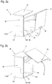
- Fig. 1 shows an isometric view of an upper cabinet, for example a kitchen, as a first embodiment of a piece of furniture with furniture walls made from a building board according to the application.
- the upper cabinet comprises a furniture body 10 with a lower shelf 11 and a top shelf 12 as well as two side walls 13.
- a rear wall is preferably provided for reasons of stability, among other things, but is not shown in this exemplary embodiment.
- the furniture body 10 is open to the front in order to gain access to the interior of the cabinet.
- a flap arrangement 20 with a one-piece flap 21 is provided in order to be able to close the opening of the furniture body 10.
- the one-piece flap 21 is pivotably mounted along its upper horizontal side edge.
- fittings 30 are provided which are connected to the one-piece flap 21 by means of a lever mechanism 31 in the upper region thereof.
- the fittings 30 are arranged within the respective side wall 13 (with the exception of the lever mechanism 31 extended in the illustrated open position). In the closed state of the flap 21, the lever mechanism 31 is completely retracted into the side wall 13 except for the assembly elements for connection to the flap 21.
- the area within the side wall 13 in which the fitting 30 is located is in the Fig. 1 indicated by a dashed line.
- the side wall 13 is characterized by side surfaces 131 which are ideally in one piece and can have a consistently identical surface quality over the entire surface.
- the surface of the one-piece side faces 131 can produce design effects by means of different patterns, surface properties or different colors. This preferably applies both to an outer of the side surfaces 131 and to an inner of the side surfaces 131 facing the interior of the furniture body 10.
- the side walls 13 also have an end face 132 which has an opening 133 in the area of the fitting 30 into which the Lever mechanism 31 of the fitting 30 is immersed or from which the lever mechanism 31 extends. In the closed state of the flap arrangement 20, the lever mechanism 31 is completely immersed in the opening 133 apart from any fastening means with which it is connected to the one-piece flap 21 here.
- the end face 132 is provided with a narrow-side coating 134, which can be designed as edge banding 134.
- the side walls 13 are made of building panels 40 that are used in connection with the Figures 5ff . are explained in more detail.
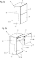
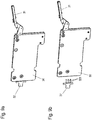
- FIG. 2a and 2b Another wall cabinet is shown as an example of a piece of furniture with a side wall according to the application, each in an isometric view.
- a one-piece flap 21 is provided as a flap arrangement 20 in order to close a furniture body 10 towards the front.
- the two Figures 2a and 2b differ in the opening state of the flap arrangement 20.
- Fig. 2a shows a partially open state of the flap arrangement 20, where to Figure 2b the maximum opening state of the flap arrangement 20 reproduces.
- a lifting and swiveling fitting is provided which enables a combined swiveling and sliding movement of the one-piece flap 21.
- the in Figure 2b In the in Figure 2b In the fully open position shown, at least a part of the flap 21 is positioned above the top panel 12 of the furniture body 10.
- the flap 21 is easily accessible in the open position in order to be able to close it again.
- the side walls 13 are made from building panels 40 which the fitting 30 has already been added to.
- FIG. 3a shows the flap assembly 20 in a closed and Figure 3b in an open position.
- a two-part flap arrangement 20 which has an upper flap part 22 and a lower flap part 23.
- the side walls 13 are made of building panels 40 which receive a fitting 30.
- This is coupled with lever works 31 both with the upper flap part 22 and with the lower flap part 23.
- additional hinges 25 are provided which couple the upper and lower flap parts 22, 23 with one another in a pivotable manner along their connecting line. Depending on the design of the flap fitting, the hinges can also be omitted.
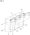
- Fig. 4 shows a further upper cabinet with furniture body 10 and flap arrangement 20, in which fittings 30 for guiding the flap arrangement 20 in a building board 40 according to the application are arranged.
- the furniture body 10 has an interior space divided by vertical partitions 14.
- two partition walls 14 are provided, which divide the interior space into three sections.
- each partition 14 is made from a building board 40.
- the arrangement shown can, however, also be implemented with only one partition wall or more than the two partition walls 14 shown.
- the flap arrangement 20 is in two parts with an upper flap part 22 and a lower flap part 23.
- the width of the flap arrangement 20 and also the upper and lower flap parts 22, 23 extends over the entire furniture body 10.
- the present fittings 30 are also arranged in the partition walls 14. Both the side walls 13 and the partition walls 14 are made from building boards 40 according to the application.
- the building boards are characterized by continuous side surfaces with a surface look and feel that are uniform over the entire surface. In particular, no transition in the area of the edge of the fitting 30 can be seen in the surface.
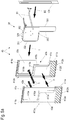
- FIG Figure 5a A first embodiment of a building board 40 with which this is achieved is shown in FIG Figure 5a shown in an exploded isometric drawing.
- the construction panel 40 shown can be used, for example, as a side wall 13 in the exemplary embodiments of FIG Figures 1-4 be used and also as a partition 14 in the embodiment of Fig. 4 .
- the building board 40 comprises two basic elements, which are mirror-inverted here and each have a plate-shaped core half 41a, 41b, both of which are provided with a recess 42a and 42b, respectively. After a later assembly, the two core halves 41a, 41b together form a core 41 of the building board 40.
- the recesses 42a and 42b can also be designed differently. The shape of the recesses 42a or 42b depends on the fitting to be used and its external geometry.
- the core halves 41a, 41b are made, for example, from a chipboard or a medium or high density fiberboard (MDF - Medium Density Fiberboard or HDF - High Density Fiberboard).
- the core halves 41a, 41b each have a rectangular oversize of the size that will later have the side or partition in the furniture body to be manufactured (see, for example, side wall 13 of the furniture body 10 according to the exemplary embodiments of FIG Figures 1-4 ).
- each of the core halves 41a, 41b a large flat recess 42a, 42b is made, which is open to a first end face 411a, 411b. Only in the upper and / or lower area of the core halves 41a, 41b does a narrow section of the end face 411a, 411b remain on this side.
- the recesses 42a, 42b can be designed mirror-symmetrically. In the area in between, the edge of the recess 42a, 42b now forms an inwardly offset end face 415a, 415b following the contour of the recess 42a, 42b.
- the first end face 411a or 411b is also referred to below as the front end face 411a, 411b.
- each core half 41a, 41b, one in the Figure 5a respective lower left end face 412a, 412b, a rear end face 413a, 413b and an upper end face 414a, 414b run straight in accordance with the rectangular allowance.
- core halves 41a, 41b are equally thick in the example shown, the term “core halves” also includes core halves 41a, 41b of different thicknesses in the context of the application.
- the recesses 42a, 42b correspond in their contour to the outer contour of a fitting 30 to be used, here an approximately L-shaped contour.
- the recesses 42a, 42b can be made in the core halves 41a, 41b, for example, by milling each with the symbolically illustrated milling tools 1.
- Other machining techniques such as drilling in connection with (plunge) saw cuts can also be used to produce the recesses 42a, 42b.
- an archetype process e.g. in accordance with the DIN 8580 standard
- the recess can also be pressed during the production of the plate.
- the milling can take place through the entire thickness of the respective core half 41a, 41b.
- provision can also be made for a thin wall of the material of the core halves 41a or 41b to stand in the area of the recess 42a or 42b.
- machining can be carried out from one of the side surfaces of the respective core halves 41a, 41b. Machining only from the first end face 411a or 411b is not necessary in the case of the core halves 41a, 41b.
- the recess can easily assume any depth (viewed from the original end faces 411a, 411b) and is also suitable for receiving fittings 30 with a large installation depth.
- shapes such as undercuts can be created that are not possible when machining a plate on the front.
- the core halves 41a, 41b form a core 41, in which the recesses 42a, 42b complement each other to form a recess 42 which receives the fitting 30.
- a cover layer 43a or 43b is applied, for example laminated, in a mirror-inverted manner to the core halves 41a, 41b. This can be done either before or after making the recesses 42a, 42b.
- These cover layers 43a, 43b are preferably already provided with a decorative surface. Their thickness ranges from a few tenths of a mm (millimeters) to about 2 or 3 mm.
- Typical plastic-based coating materials, lacquered paper layers, veneers or cork can be used as cover layers 43a, 43b.
- Leather or fabrics can also be used.
- the cover layers 43a, 43b can also be omitted.
- the core halves 41a, 41b can be, for example, for the production of a standard furniture wall with a thickness of 16 mm in a simple manner by means of two completely 8 mm panels, possibly already provided with the cover layers 43a, 43b on both sides, with the recesses 42a, 42b can be introduced into the core halves.
- the two panels can also already be provided with a narrow-side coating such as an edge band on the front sides.
- the recesses 42a, 42b ideally have a bottom made of the material of the core halves 41a, 41b, so that the adjoining cover layers 43a, 43b are not damaged.
- the edge band on the front face 411a, 411b can be milled back.
- the core halves 41a, 41b can be glued, with the core halves 41a, 41b in this embodiment also having a cover layer in the parting line if the starting material of the core halves 41a, 41b is already coated on both sides.
- the fitting 30 can also be glued to the back-milled edge band.
- the edge banding can also be applied subsequently if the fitting 30 has already been inserted into the recess 42.
- the narrow side coating or the edge banding covers the front housing wall of the fitting so that it is covered.
- the fitting 30 can, for example, be guided between the two core halves 41a, 41b in a first assembly step I and both core halves 41a, 41b can be closed around the fitting 30 in the manner of a shell and connected to one another in a second assembly step II.
- the narrow side coating or the edge banding 134 is applied to the end face 411a, 411b.
- the fitting 30 can first be inserted into one of the recesses, for example the recess 42b of the core half 41b. Then the second basic element, that is to say the core half 41a with the cover layer 43a and the recess 42a, is slipped over the fitting 30 and the two core halves 41a, 41b are joined together and connected to one another.
- the second basic element that is to say the core half 41a with the cover layer 43a and the recess 42a
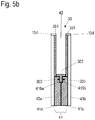
- connection of the fitting 30 with the core halves 41a, 41b or the cover layers 43a, 43b is described in connection with Figure 5b described in more detail.
- the in Figure 5a shown embodiment is in the area of the respective end face 414a, 414b of the core halves 41a, 41b on the edge of the recesses 42a, 42b in sections the respective core half 41a, 41b adjacent to the end face 415a or 415b on the side facing away from the cover layer 43a, 43b milled off so that that shoulder surfaces 416a and 416b are formed which form a shoulder with respect to the remaining side surfaces of the core halves 41a, 41b.
- the fitting 30 has two side plates 301 spaced apart from one another, which laterally delimit the fitting 30 and provide the pivot points for the lever mechanism 31.
- Spacer sleeves or bolts which connect the side plates 301 to one another and fix them parallel to one another at a defined distance, can be arranged between the side plates 301.
- screw elements can also serve as spacers, which offer the possibility of at least slightly varying the distance between the side plates 301 and thereby adapting it to the thickness of the core 41.
- tabs 302 protrude outward beyond the side plates 301 on different sides.
- the tabs 302 can be designed, for example, as a fold of correspondingly beveled side plates 301.
- the tabs 302 are arranged in a plane in the center of the side plates 301.
- staples 303 projecting transversely to the tabs 302 are arranged, for example formed from the exposed material of the tabs 302.
- Figure 5b shows a section of the building board 40 of FIG Figure 5a in an assembled state in a schematic section in the area of the edge of the inserted fitting 30.
- the tabs 302 in the Area of the shoulder surfaces 416a and 416b are defined between the core halves 41a, 41b connected to one another.
- the staples 303 are pressed into the material of the core halves 41a, 41b on both sides and thus fasten the fitting 30 in the building board 40 to the core halves 41a, 41b.
- the core halves 41a, 41b are also connected to one another in this way via the staples 303 and the tabs 302.
- the side plate 301 of the fitting 30 can also be glued flat to the bottom of the recess 42a, 42b of the core half 41a, 41b.
- the fitting 30 and the core 41 formed from the two core halves 41a and 41b preferably have the same thickness.
- the same thickness is preferably in a range from 6 mm to about 10 mm.
- the core 41 and the fitting 30 thus form a unit in which the fitting 30 is flush with the surface of the core 41 on both sides. Furthermore, the front edges of the fitting 30 also run flush with the two remaining sections of the actual first end faces 411a, 411b of the core 41.
- a narrow-side coating 134 which can be designed as an edge banding 134, is applied to the end faces 411a, 411b and the front edges of the fitting 30.
- the end face of the building panel 40 is homogeneously covered by the edge banding, so that the side panels 301 or the outer wall of the housing of the fitting 30 are covered.
- FIG. 11 shows a detail of a front view of an end face 132 of the building board 40 of FIG Figure 5a with inserted fitting.
- An edge banding 134 is applied to the end face 132 and covers both the end face 411 of the core and the side plates 301 or the housing outer wall of the fitting 30.
- the housing wall hidden behind the edging is shown here with dashed lines.
- the lever mechanism 31 of the fitting can move freely through an opening in the edge band 133.
- the narrow-side coating or the edge banding 134 is applied after the fitting has been installed in the recesses 42.
- the edge band 134 can also be applied beforehand to the end face 411a, 411b of the core halves 41a, 41b. In this case the edge trim 134 is milled back and glued to the front housing outer wall when the fitting 30 is inserted.
- the structural element 40 is produced, from which a side wall or an intermediate wall, for example, which already contains the fitting 30, can be manufactured in a simple manner during the manufacture of a furniture body.
- the building board 40 has a machinable section, within which the building board 40 is in the manufacturing process of the Furniture body can be shortened, for example, can be sawed off, or can be milled into the profiles or assembly elements can be attached.
- a machinable section 412a 'or 412b' is provided - for example only on the lower end face 412a, b - within which the building board can be processed without the fitting 30 being damaged and without the building board 40 and in particular the fastening of the fitting 30 loses stability.
- the protruding machinable section 412a ', b' which is indicated in the figure by hatching, can also accommodate fastening elements, for example for elements for organizing the interior of the furniture, or further fittings can be fastened if necessary.
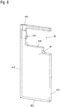
- Fig. 6 shows an isometric exploded view of an alternative structure of a building board 40 and illustrates its production.
- the building board 40 has a core 41, again manufactured, for example, from a chipboard or MDF or HDF board.
- a recess 42 for the fitting 30 is made in the core 41, for example milled in from one of the side surfaces.
- the recess 42 is open towards a first end face 411 of the core 41, so that the lever mechanism 31 of the fitting can dip into the building board 40.
- the core 41 is in one piece and only adjoins below the fitting 30.
- the core 41 and the fitting 30 can be connected to one another via connecting elements not shown here, for example screws, clamps, pins, staples or the like.
- An adhesive connection can also be provided in addition to the connection elements mentioned or as the only connection.
- Cover layers 43a, 43b are applied, in particular glued or laminated on, from each side to the arrangement made up of the core 41 and the fitting 30, which may be connected to it.
- the fitting 30 is selected with regard to its material and the material thickness, for example of the side plates of the fitting 30, so that it is not pressed in even during a lamination process, which could lead to an unevenness of the surface of the cover layers 43a, 43b. Smaller unevennesses in the side plates of the fitting 30 are compensated for by the cover layers 43a, 43b or by the adhesive layer located between the cover layer 43a, 43b and the fitting 30. Such minor unevenness can arise, for example, from the bearing points of bolts which serve to pivot the lever mechanism 31 in the fitting 30.
- FIG. 6 The symbolized manufacturing process of the building board 40, in which the core 41 and the fitting 30 are initially aligned with one another and optionally connected to one another and then merged with the cover layers 43a, b to form the building board 40, enables the use of a fitting 30, which is as shown for example, extends over the entire width of the building board 40. In this way, larger and more complex fittings 30 can also be used in the building board 40 than would be possible in a pocket of a side wall milled out at the end.
- a machinable section 412 ' is provided as an overhang, within which the building board 40 can be processed or within which further elements can be mounted.
- the narrow side coating provided for the end face 411 is, for example, an edge band.
- the edge band covers the end face of the core 41 and the end face of the outer wall of the fitting 30.
- Fig. 7 shows a further embodiment of a building board 40 with a core 41 and an integrated fitting 30.
- a two-part flap with sections 22, 23 is mounted on the fitting 30.
- an outer cover layer is shown as transparent in order to show the inner structure of the building board 40.
- the core 41 of the building board 40 does not consist of a homogeneous material, but is designed as a composite material. In the edge areas, this core 41 is still made of a compacted material, for example a chipboard, an HDF or an MDF board. In an inner region, in particular in the lower part of the core 41, in which the fitting 30 is made narrower, a light honeycomb structure material 417, for example a cardboard material, is provided. By using the honeycomb structure material 417, the weight of the building panel 40 and also the material cost can be reduced. In particular in connection with the attached and preferably glued-on cover layers 43a, 43b, sufficient stability of the building board 40 is nevertheless achieved.
- the building board 40 shown again has protruding machinable sections 412 ', 413' and 414 'as processing zones, in this example on three end faces 412, 413 and 414, ie on all end faces except the first end face 411 into which the fitting 30 is inserted .
- the processing zones are sufficiently spaced from the fitting 30 so that the stability of the building board 40 is not impaired.
- an assembly zone that extends somewhat further to the fitting 30 can be marked, within which assembly elements, for example connecting elements to further walls of the furniture body, can be attached to the building board 40.
- dashed cutting lines 2 are indicated by way of example, along which the building board 40 can be cut to length during the manufacture of a furniture body.
- the prefabricated building board 40 with already integrated fitting 30 can thus be used in order to produce a piece of furniture with a wall-integrated fitting with little effort.
- electrical lines and also further electrical components can also be integrated into the building board 40 for electrification of the piece of furniture.
- lighting equipment such as LED lights is also possible.
- the size of the protruding machinable sections 412 ', 413' and 414 'or their edges can preferably be indicated on the building board 40 in order to prevent machining in an area in which the machining could lead to damage to the fitting 30 or the
- the integrity or stability of the building plate 40 is influenced.
- An advantageous way of specifying the edges of the protruding machinable sections 412 ', 413' and 414 ' is to print the edges on a removable protective film with which the cover layers 43a, b are also protected during further processing.
- the position and dimensions of an integrated fitting 30 can also be specified in this way. Processing areas for fastening means for interior organizations and / or furniture connection areas can also be drawn in on the protective film. These areas can also lie in a surface area that cannot be sawn off.
- information about the building board 40 and / or its workability can be integrated into the building board 40 in the form of a readable data carrier.
- an RFID (Radio Frequency IDentification) transponder can be inserted into the building board 40, preferably below one of the cover layers 43a, b. If necessary, the position of the RFID transponder can be indicated on the outside of the building board 40, e.g. again on the protective film mentioned.
- the RFID transponder can contain e.g. an article number, the year of construction, a batch, color information, dimensions and position of the fitting, type and load-bearing capacity of the fitting, etc. as data that can be read out wirelessly via a reader.
- a reader e.g. a reader that can be read out wirelessly via a reader.
- the furniture manufacturer it can be ensured, for example, directly on a processing machine, that the correct type of building board is supplied for a piece of furniture to be manufactured.
- a wall hanger is provided, preferably on the rear end face 413 of the building board 40, with which the piece of furniture can be hung on a building wall.
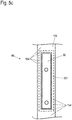
- Fig. 8 shows a core 41 for a building board 40, which is prepared for receiving a wall hanger.
- the core 41 has a receiving channel 418 pointing from the recess 42 to the rear end face 413, into which the wall hanger can be inserted.
- a further channel 419 is introduced into the core 41, which extends into the receiving channel 418.
- adjusters of an inserted wall hanger for example for height and / or inclination adjustment, can be achieved with the aid of a tool in order to be able to adjust a piece of furniture suspended on a building wall.
- the receiving channel 418 can extend into the end face 415 of the recess 42. In this way, the wall hanger can be connected directly to the fitting 30.
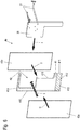
- Figure 9a is a in the core 41 of the Fig. 8 insertable fitting 30 shown in an isometric view.
- a wall hanger 32 is mounted, which when the fitting 30 is inserted into the core 41 according to FIG Fig. 8 protrudes into the receiving channel 418. It can be provided that the wall hanger 32 is placed on a screw head or hook of a screw screwed into the building wall.
- Figure 9b shows the wall hanger 32 before it is mounted on the fitting 30.
- the wall hanger 32 has connecting means with which it can be mounted on the fitting 30 with as little tools as possible.
- connecting pins 321 are provided as connecting means, which snap into corresponding receptacles in the fitting 30 when the wall hanger 32 is inserted into the fitting 30.
- the wall hanger 32 can, if necessary, be inserted from the outside into the receiving channel 418 of a building board 40 in the fitting 30.
- a wall hanger of the building board 40 could also be attached to the core 41.
- a large-area force distribution from the wall hanger 32 to the core 41 is advantageously achieved and local forces acting on the material of the core 41 are prevented from exceeding the tensile strength of the (wood) material of the core 41 .
- forces that act on the fitting 30, for example the weight and lever forces of a door guided by the fitting 30 or Flap effectively derived directly from the wall hanger 32 onto the building wall.
Description
Die Erfindung betrifft eine Bauplatte für eine Möbelwand eines Möbelkorpus nach Anspruch 1. Die Erfindung betrifft weiterhin ein Verfahren zur Herstellung einer derartigen Bauplatte nach Anspruch 22, sowie einer Möbelwand nach Anspruch 27.The invention relates to a building board for a furniture wall of a furniture body according to claim 1. The invention also relates to a method for producing such a building board according to
Möbel, insbesondere Küchenmöbel wie Unterschränke oder Hängeschränke weisen in der Regel einen nach vorne offenen Möbelkorpus auf, an dem über Beschläge geführte bewegbare Möbelteile montiert sind. Die bewegbar geführten Möbelteile können Schubkästen mit einer Schubkastenfront oder Türen oder Klappen sein, die bei einem Möbelkorpus einzeln oder in unterschiedlichen Kombinationen eingesetzt werden können. Die vorliegende Anmeldung bezieht sich insbesondere auf die Verwendung von Türen und Klappen als bewegbaren Möbelteilen. Türen und Klappen werden im Rahmen dieser Anmeldung anhand der Ausrichtung ihrer Schwenkachse unterschieden, die bei Türen vertikal und bei Klappen horizontal verläuft.Furniture, in particular kitchen furniture such as base cabinets or wall cupboards, generally have a furniture body that is open to the front and on which movable furniture parts guided by fittings are mounted. The movably guided furniture parts can be drawers with a drawer front or doors or flaps that can be used individually or in different combinations on a furniture body. The present application relates in particular to the use of doors and flaps as movable furniture parts. In the context of this application, doors and flaps are distinguished on the basis of the orientation of their pivot axis, which runs vertically in the case of doors and horizontally in the case of flaps.
Die Türen und Klappen können hierbei einteilig sein oder aus mehreren Einzelteilen bestehen, wie zum Beispiel eine Faltklappe, bei der verschiedene Teile der Klappe sich im Bewegungsablauf relativ zueinander bewegen.The doors and flaps can be in one piece or consist of several individual parts, such as a folding flap in which different parts of the flap move relative to one another in the course of movement.
Zur Führung von Türen werden in der Regel Türscharniere verwendet, die an der Seite der Schwenkachse zwischen Möbelkorpus und Tür angeordnet sind. Eine vergleichbare Anordnung von Scharnieren kann grundsätzlich auch bei Klappen eingesetzt werden. Diese Scharniere sind dann entlang einer oberen Seitenkante der Klappe angeordnet. Häufig ist es jedoch gewünscht, die Klappen in einer kombinierten Schwenk- und Schiebebewegung zu öffnen, um, beispielsweise bei einem Hängeschrank, einen größtmöglichen Zugang zum Schrankinnenraum zu erhalten, ohne dass die Klappe bis in eine waagerechte Position verschwenkt werden muss, in der sie vom Benutzer zum Schließen nicht oder nur noch schlecht erreichbar ist. Aus diesem Grund haben sich spezielle Klappenbeschläge etabliert, die nicht entlang der Schwenkachse zwischen dem Möbelkorpus und der Klappe angeordnet werden, sondern seitlich an (in der Regel beiden) Seitenkanten zwischen der Klappe und der Seitenwand des Möbelkorpus.Door hinges, which are arranged on the side of the pivot axis between the furniture body and the door, are generally used to guide doors. A comparable arrangement of hinges can in principle also be used for flaps. These hinges are then arranged along an upper side edge of the flap. However, it is often desired to open the flaps in a combined pivoting and sliding movement in order, for example in the case of a hanging cabinet, to obtain the greatest possible access to the cabinet interior without the flap having to be pivoted into a horizontal position in which it is from User to close cannot be reached or is difficult to reach. For this reason, special flap fittings have become established that are not arranged along the pivot axis between the furniture body and the flap, but laterally on (usually both) side edges between the flap and the side wall of the furniture body.
Bekannt sind derartige Türscharniere oder Klappenbeschläge zur Montage an einer Innenseite der Seitenwand oder der Seitenwände des Möbelkorpus. Die Beschläge ragen dabei jedoch unvermeidbar in den Innenraum des Möbelkorpus, was zum einen den nutzbaren Stauraum innerhalb des Möbelkorpus verringert und zum anderen auch eine Strukturierung des Innenraums des Möbelkorpus beeinträchtigt. Ebenso wird eine Reinigung des Innenraums, insbesondere der Innenseite der Seitenwand des Möbelkorpus, durch die aufmontierten Beschläge erschwert. Nicht zuletzt ist eine Seitenwand, auf der keine Beschläge montiert sind, aus optischen Gründen erstrebenswert.Such door hinges or flap fittings for mounting on an inside of the side wall or the side walls of the furniture body are known. However, the fittings inevitably protrude into the interior of the furniture body, which on the one hand reduces the usable storage space within the furniture body and on the other hand also impairs the structuring of the interior of the furniture body. Cleaning of the interior, in particular the inside of the side wall of the furniture body, is also made more difficult by the mounted fittings. Last but not least, a side wall on which no fittings are mounted is desirable for visual reasons.
Zur Montage von Türscharnieren ist es bekannt, in eine Stirnseite einer Seitenwand eine Tasche zu fräsen, in die das Türscharnier von vorne einsetzbar ist. Auf diese Weise bleibt die Innenseite der Seitenwand frei. Ein zum Einsatz in einer derartigen eingefrästen Tasche geeignetes Scharnier ist beispielsweise aus der Druckschrift
Zur Verwendung eines derartigen Scharniers wird von der Stirnseite einer bereits für den Möbelkorpus vorbereiteten Möbelwand, insbesondere Seitenwand, die genannte Einfräsung vorgenommen. Diese Vorgehensweise eignet sich jedoch nur für Türscharniere mit einer sehr geringen Einbautiefe. Dieses liegt in der beschränkten Frästiefe begründet, mit der wirtschaftlich im Herstellungsprozess eine derartige Tasche von der Stirnseite aus in die Möbelwand gefräst werden kann. Auch die Einbaudicke des in eine solche eingefräste Tasche eingesetzten Türscharniers ist sehr begrenzt, da Möbelwände üblicherweise nur eine Wandstärke von etwa 16-20 mm (Millimetern) aufweisen. Beim Fräsvorgang muss eine gewisse Mindestwandstärke seitlich der ausgefrästen Taschen verbleiben, da eine zu dünne Wand bereits im Fräsvorgang reißen oder brechen würde bzw. so deformiert würde, dass sie keine einwandfreie Oberfläche mehr aufweist.To use such a hinge, the mentioned milling is made from the end face of a furniture wall, in particular a side wall, which has already been prepared for the furniture body. However, this procedure is only suitable for door hinges with a very small installation depth. This is due to the limited milling depth with which such a pocket can be economically milled into the furniture wall from the front side in the manufacturing process. The built-in thickness of the door hinge used in such a milled pocket is also very limited, since furniture walls usually only have a wall thickness of about 16-20 mm (millimeters). During the milling process, a certain minimum wall thickness must remain on the side of the milled pockets, since a wall that is too thin would tear or break during the milling process or would be deformed in such a way that it no longer has a perfect surface.
Bereits der Einsatz größerer und komplexer Türscharniere ist auf diese Weise nicht möglich. Klappenscharniere weisen in der Regel eine große Einbautiefe im Bereich von mehr als 10 oder 15 cm (Zentimetern) auf, die durch eine Fräsung von der Stirnseite aus nicht zu erzielen ist.Even the use of larger and more complex door hinges is not possible in this way. Flap hinges usually have a large installation depth in the area of more than 10 or 15 cm (centimeters), which cannot be achieved by milling from the front side.
Aus der Druckschrift
Aus der Druckschrift
Es ist eine Aufgabe der vorliegenden Erfindung, ein Möbel oder Möbelkorpus zu schaffen, der oder das leicht mit beispielsweise einem Beschlag mit einer größeren Einbautiefe ausgestattet sein kann und dennoch mit geringem Herstellungsaufwand gefertigt werden kann. Zudem soll der Möbelkorpus sich durch eine einheitliche Oberflächenbeschaffenheit sowohl auf seiner Außenals auch seiner Innenseite auszeichnen. Es ist eine weitere Aufgabe, eine Bauplatte für eine Möbelwand eines derartigen Möbelkorpus bereitzustellen, mit der eine unaufwändige Herstellung des Korpus möglich ist. Schließlich ist es eine Aufgabe, ein Verfahren zur Herstellung einer solchen Bauplatte und einer Möbelwand anzugeben.It is an object of the present invention to create a piece of furniture or a furniture body that can easily be equipped with, for example, a fitting with a greater installation depth and yet can be manufactured with little manufacturing effort. In addition, the furniture body should be characterized by a uniform surface texture both on its outside and on its inside. It is a further object to provide a construction panel for a furniture wall of such a furniture body, with which an inexpensive manufacture of the body is possible. Finally, it is an object to provide a method for producing such a building panel and a furniture wall.
Diese Aufgabe wird gelöst durch eine Bauplatte, einen Möbelkorpus, ein Möbel, sowie ein Verfahren zur Herstellung einer Bauplatte bzw. einer Möbelwand mit den Merkmalen des jeweiligen unabhängigen Anspruchs. Vorteilhafte Ausgestaltungen und Weiterbildungen sind Gegenstand der abhängigen Ansprüche.This object is achieved by a building board, a furniture body, a piece of furniture and a method for producing a building board or a furniture wall with the features of the respective independent claim. Advantageous refinements and developments are the subject of the dependent claims.
Die Bauplatte weist im Bereich zumindest einer der weiteren Stirnseiten mindestens einen zerspanbaren Abschnitt auf, der außerhalb der Ausnehmung liegt. Die für den Beschlag vorbereitete oder ihn bereits aufweisende Bauplatte kann wie eine übliche Materialplatte innerhalb des zerspanbaren Abschnitts bearbeitet, z.B. abgelängt werden, um eine Möbelwand für einen Möbelkorpus zu fertigen. Mit wenigen und vor allem konventionellen Bearbeitungsschritten kann ein Möbelkorpus gefertigt werden, der mit elegant in der Möbelwand aufgenommenen Beschlägen versehen ist. Auch Beschläge mit einer großen Einbautiefe können eingesetzt werden, wenn sie bei der Herstellung der Bauplatte bereits in diese integriert werden.The build plate points in the area at least one of the further end faces has at least one machinable section which lies outside the recess. The one for the fitting A building board that has been prepared or already has it can be processed like a conventional material board within the machinable section, for example cut to length, in order to produce a furniture wall for a furniture body. With a few and, above all, conventional processing steps, a furniture body can be manufactured which is provided with fittings elegantly accommodated in the furniture wall. Fittings with a large installation depth can also be used if they are already integrated into the building board during manufacture.
In einer vorteilhaften Ausgestaltung der Bauplatte ist der Kern zwischen zwei seitlich aufgebrachten Decklagen angeordnet. Bevorzugt ist der Beschlag in der Ausnehmung aufgenommen. Die Bauplatte ist dann ein Verbundelement aus einem Kern und Decklagen, wobei die zur Aufnahme des Beschlags notwendige Ausnehmung im Kern erfindungsgemäß bereits bei der Herstellung der Bauplatte eingebracht wird, bevor die Decklagen aufgebracht werden. So bestehen keine Einschränkungen für die Größe der Ausnehmung, wie sie bei einem Einbringen der Ausnehmung für den Beschlag bei einer bereits mit Decklagen versehenen Bauplatte vorliegen. So können auch große, in ihrer Tiefe beispielsweise die gesamte oder annähernd gesamte Breite der späteren Möbelwand einnehmende Beschläge eingesetzt werden. Gleichzeitig weist die Bauplatte auf beiden Seitenflächen jeweils eine bevorzugt einstückige, durchgehende Decklage auf.In an advantageous embodiment of the building board, the core is arranged between two laterally applied cover layers. The fitting is preferably received in the recess. The building board is then a composite element made up of a core and cover layers, the recess required for receiving the fitting in the core, according to the invention, already being introduced during the manufacture of the building board, before the cover layers are applied. There are no restrictions on the size of the recess, as are the case when the recess for the fitting is made in a building board that has already been provided with cover layers. In this way, it is also possible to use large fittings that, for example, take up the entire or almost the entire width of the later furniture wall in terms of their depth. At the same time, the building board has a preferably one-piece, continuous cover layer on both side surfaces.
Erfindungsgemäß weist der Beschlag eine Gehäusewandung auf und ist, beispielsweise mit dieser Gehäusewandung mit dem Kern verschraubt und/oder verklammert und/oder verklebt, bevorzugt bevor die Decklagen aufgebracht werden. Es entsteht so eine Bauplatte für einen Möbelkorpus mit einem fest integrierten Beschlag, wodurch die Herstellung des Möbelkorpus vereinfacht wird.According to the invention, the fitting has a housing wall and is, for example, screwed and / or clamped and / or glued to the core with this housing wall, preferably before the cover layers are applied. The result is a building board for a furniture body with a permanently integrated fitting, which simplifies the manufacture of the furniture body.
In einer weiteren vorteilhaften Ausgestaltung der Bauplatte ist der Kern aus zwei Kernhälften gebildet, die in einer Ebene parallel zu Seitenflächen der Bauplatte aneinander liegen.In a further advantageous embodiment of the building board, the core is formed from two core halves which lie against one another in a plane parallel to side surfaces of the building board.
Bevorzugt ist der Beschlag mit den Kernhälften und/oder zumindest einer der Decklagen verbunden, um auf ihn wirkende Kräfte möglichst sicher an die Bauplatte weiterleiten zu können. Beispielsweise kann zur Verbindung mindestens eine der Kernhälften entlang eines Randes der jeweiligen Ausnehmung eine reduzierte Dicke aufweisen, derart, dass zur Ausnehmung hin eine Absatzfläche gebildet ist, auf der der Beschlag mit mindestens einer über seinen Rand hervorstehenden Lasche aufliegt. Bevorzugt ist dabei aus der mindestens einen Lasche mindestens eine Krampe ausgestellt, die im Bereich der Absatzfläche in das Material mindestens einer Kernhälfte eingepresst ist. Dieses stellt eine im Herstellungsprozess der Wand besonders einfache Verbindungsart dar, um den Beschlag mit dem Kern zu verbinden. Alternativ oder zusätzlich kann der Beschlag mit dem Kern und/oder zumindest einer der beiden Decklagen verklebt sein.The fitting is preferably connected to the core halves and / or at least one of the cover layers in order to be able to transfer forces acting on it to the building board as safely as possible. For example, for the connection at least one of the core halves can have a reduced thickness along an edge of the respective recess, such that a shoulder surface towards the recess is formed on which the fitting rests with at least one tab protruding over its edge. At least one staple is preferably issued from the at least one flap and is pressed into the material of at least one core half in the area of the heel surface. This represents a particularly simple type of connection in the production process of the wall in order to connect the fitting to the core. Alternatively or additionally, the fitting can be glued to the core and / or at least one of the two cover layers.
In einer weiteren vorteilhaften Ausgestaltung der Bauplatte weist der Beschlag zwei Gehäuseaußenwandungen aufweist, deren maximaler Abstand kleiner ist als die Dicke des Kerns, so dass der Beschlag in der Bauplatte aufgenommen ist, ohne dass er sich außen auf den Decklagen abzeichnet. Für den Beschlag steht eine Einbaubreite zu Verfügung, die maximal der Dicke des Kerns entspricht. Auch bei einer Bauplatte in üblicher Stärke von Möbelwänden können so Beschläge eingesetzt werden, deren Breite bis zu etwa 20 mm beträgt.In a further advantageous embodiment of the building board, the fitting has two outer housing walls, the maximum distance between which is smaller than the thickness of the core, so that the fitting is received in the building board without showing on the outside of the cover layers. An installation width is available for the fitting that corresponds at most to the thickness of the core. Fittings with a width of up to about 20 mm can also be used in the case of a building board of the usual thickness for furniture walls.
In einer weiteren vorteilhaften Ausgestaltung der Bauplatte umfasst diese einen integrierten Datenträger, in dem Informationen zu der Bauplatte und/oder einem integrierten Beschlag gespeichert sind. Bevorzugt weist sie zudem einen integrierten Transponder, z.B. einen RFID-Transponder auf, der den Datenträger umfasst und der drahtlos ausgelesen werden kann. Bei einem Möbelhersteller kann so durch ein Auslesen z.B. unmittelbar an einer Bearbeitungsmaschine sichergestellt werden, dass der richtige Typ Bauplatte für ein herzustellendes Möbel zugeführt wird.In a further advantageous embodiment of the building board, it comprises an integrated data carrier in which information on the building board and / or an integrated fitting is stored. It preferably also has an integrated transponder, e.g. an RFID transponder, which includes the data carrier and which can be read out wirelessly. In the case of a furniture manufacturer, a readout, for example directly on a processing machine, can ensure that the correct type of building board is supplied for a piece of furniture to be manufactured.
In einer weiteren vorteilhaften Ausgestaltung der Bauplatte ist eine Position des mindestens einen zerspanbare Abschnitts markiert, z.B. auf einer abziehbaren Schutzfolie. Auch eine Position eines integrierten Transponders kann auf der abziehbaren Schutzfolie markiert sein, um eine fehlerhafte Bearbeitung zu verhindern.In a further advantageous embodiment of the building board, a position of the at least one machinable section is marked, for example on a removable protective film. A position of an integrated transponder can also be marked on the removable protective film in order to prevent incorrect processing.
In einer weiteren vorteilhaften Ausgestaltung der Bauplatte ist ein Wandaufhänger integriert, der zu großflächigen Kraftübertragung an dem Beschlag montiert sein kann.In a further advantageous embodiment of the building board, a wall hanger is integrated, which can be mounted on the fitting to transmit force over a large area.
In einer weiteren vorteilhaften Ausgestaltung der Bauplatte ist auf mindestens eine der Stirnseite beider Kernhälften bzw. des Kerns eine Schmalseitenbeschichtung, z.B. ein Kantenumleimer aufgebracht. Diese kann sich ein- oder mehrteilig über die gesamte Länge der Stirnseite erstrecken. Bevorzugt wird im Bereich der vorderen Stirnseite des Kern der Kantenumleimer erst aufgebracht, wenn der Beschlag integriert bzw. eingesetzt ist, wobei der Kantenumleimer zumindest abschnittsweise auf dem Beschlag angeordnet ist. Auf diese Weise können beispielsweise die Kanten der Seitenplatten des Beschlags abgedeckt werden.In a further advantageous embodiment of the building board, a narrow side coating, e.g. an edge band, is applied to at least one of the end faces of both core halves or the core. This can extend in one or more parts over the entire length of the end face. The edge band is preferably only applied in the area of the front end face of the core when the fitting is integrated or inserted, the edge band being arranged at least in sections on the fitting. In this way, for example, the edges of the side panels of the fitting can be covered.
Erfindungsgemäß weist der Beschlag ein Hebelwerk auf, das das bewegliche Möbelteil führt, und befindet sich im geschlossenen Zustand des beweglichen Möbelteils das Hebelwerk zwischen den Decklagen. Der Beschlag ist dann so vollständig in der Bauplatte integriert, dass - unvermeidbar - nur das Hebelwerk, und auch dieses nur im geöffneten Zustand des bewegbaren Möbelteils, sichtbar ist.According to the invention, the fitting has a lever mechanism that guides the movable furniture part, and when the movable furniture part is closed, the lever mechanism is located between the cover layers. The fitting is then so completely integrated in the building board that - unavoidably - only the lever mechanism, and this only when the movable furniture part is open, is visible.
Anspruch 22 definiert ein erfindungsgemäßes Verfahren zum Herstellen einer Bauplatte. Es wird ein plattenförmiger Kern bereitgestellt und eine Ausnehmung in den Kern eingebracht, die sich zumindest entlang eines Abschnitts einer ersten Stirnseite des Kerns erstreckt, wobei an zumindest einer weiteren Stirnseite des Kerns außerhalb der Ausnehmung mindestens ein überstehender zerspanbarer Abschnitt verbleibt. Weiter wird wenigstens eine seitliche Decklage auf den Kern aufgebracht - vor oder nach dem Einbringen der Ausnehmung. Es wird ein Beschlag vor oder nach dem Aufbringen der seitlichen Decklage in der Ausnehmung angeordnet. Es ergeben sich die im Zusammenhang mit der Bauplatte genannten Vorteile.
In einer vorteilhaften Ausgestaltung des Verfahrens wird in einem weiteren Schritt der mindestens eine überstehende zerspanbare Abschnitt von außen erkennbar markiert. Bevorzugt wird dazu eine eine Schutzfolie aufgebracht, auf der mindestens eine zerspanbare Abschnitt markiert ist.In an advantageous embodiment of the method, in a further step, the at least one protruding machinable section is marked so as to be recognizable from the outside. For this purpose, a protective film is preferably applied, on which at least one machinable section is marked.
In einer weiteren vorteilhaften Ausgestaltung des Verfahrens wird eine Schmalseitenbeschichtung auf die erste Stirnseite vor dem Einsetzen des Beschlags in die Ausnehmung aufgebracht, wobei die Schmalseitenbeschichtung zumindest Teile der Stirnseite einer Gehäusewandung des Beschlags verdeckt.In a further advantageous embodiment of the method, a narrow side coating is applied to the first end face before the fitting is inserted into applied the recess, wherein the narrow side coating covers at least parts of the end face of a housing wall of the fitting.
Anspruch 27 definiert ein erfindungsgemäßes Verfahren zum Herstellen einer Möbelwand und umfasst ein zerspanendes Bearbeiten, insbesondere Ablängen einer Bauplatte mit einem integrierten Beschlag in zumindest einem zerspanbaren Abschnitt. Auf diese Weise kann mit geringem Herstellungsaufwand mit wenigen und vor allem konventionellen Bearbeitungsschritten ein Möbelkorpus gefertigt werden, der mit elegant in der Möbelwand aufgenommenen Beschlägen versehen ist. Auch Beschläge mit einer großen Einbautiefe können eingesetzt werden, wenn sie bei dem Herstellen des Möbelkorpus bereits in die verwendeten der Bauplatten integriert sind.Claim 27 defines a method according to the invention for producing a furniture wall and comprises machining, in particular cutting a building board to length with an integrated fitting in at least one machinable section. In this way, a furniture carcass can be manufactured with little manufacturing effort using a few and, above all, conventional processing steps, which is provided with fittings elegantly accommodated in the furniture wall. Fittings with a large installation depth can also be used if they are already integrated into the construction panels used when the furniture body is manufactured.
Die Erfindung wird nachfolgend anhand von Ausführungsbeispielen mithilfe von Figuren näher erläutert. Die Figuren zeigen:
- Fig. 1
- ein erstes Ausführungsbeispiel eines Möbels mit einer Seitenwand erstellt aus einer anmeldungsgemäßen Bauplatte;
- Fig. 2a, 2b
- ein zweites Ausführungsbeispiel eines Möbels mit einer Seitenwand erstellt aus einer anmeldungsgemäßen Bauplatte in zwei verschiedenen Öffnungsstellungen einer Klappe;
- Fig. 3a, 3b
- ein drittes Ausführungsbeispiel eines Möbels mit einer Seitenwand erstellt aus einer anmeldungsgemäßen Bauplatte in zwei verschiedenen Öffnungsstellungen einer Klappe;
- Fig. 4
- ein viertes Ausführungsbeispiel eines Möbels mit einer Seitenwand erstellt aus einer anmeldungsgemäßen Bauplatte;
- Fig. 5a
- ein erstes Ausführungsbeispiel einer Bauplatte für eine Möbelwand in einer schematischen Explosionszeichnung;
- Fig. 5b
- einen Ausschnitt der Bauplatte der
Fig. 5a in einem zusammengesetzten Zustand in einem schematischen Schnitt im Bereich des Rands des eingesetzten Beschlags; - Fig. 5c
- einen Ausschnitt einer Frontansicht einer Stirnseite der Bauplatte der
Fig. 5a mit eingesetztem Beschlag; - Fig. 6
- ein zweites Ausführungsbeispiel einer Bauplatte für eine Möbelwand in einer schematischen Explosionszeichnung;
- Fig. 7
- ein drittes Ausführungsbeispiel einer Bauplatte für eine Möbelwand in einer schematischen Zeichnung;
- Fig. 8
- ein Ausführungsbeispiel eines Kerns einer Bauplatte für eine Möbelwand in einer schematischen Zeichnung; und
- Fig. 9a, b
- ein Beschlag mit einer Wandhalterung zur Verwendung in einer Bauplatte in verschiedenen Darstellungen.
- Fig. 1
- a first embodiment of a piece of furniture with a side wall created from a building board according to the application;
- Figures 2a, 2b
- a second embodiment of a piece of furniture with a side wall created from a building board according to the application in two different opening positions of a flap;
- Figures 3a, 3b
- a third embodiment of a piece of furniture with a side wall created from a building board according to the application in two different opening positions of a flap;
- Fig. 4
- a fourth embodiment of a piece of furniture with a side wall created from a building board according to the application;
- Figure 5a
- a first embodiment of a building panel for a furniture wall in a schematic exploded drawing;
- Figure 5b
- a section of the building board of the
Figure 5a in an assembled state in a schematic section in the region of the edge of the fitting used; - Figure 5c
- a detail of a front view of an end face of the building panel of
Figure 5a with inserted fitting; - Fig. 6
- a second embodiment of a building board for a furniture wall in a schematic exploded view;
- Fig. 7
- a third embodiment of a building board for a furniture wall in a schematic drawing;
- Fig. 8
- an embodiment of a core of a building board for a furniture wall in a schematic drawing; and
- Figures 9a, b
- a fitting with a wall bracket for use in a building panel in various representations.
Der Oberschrank umfasst einen Möbelkorpus 10 mit einem Unterboden 11 und einem Oberboden 12 sowie zwei Seitenwänden 13. Eine Rückwand ist bevorzugt unter anderem aus Stabilitätsgründen vorhanden, in diesem Ausführungsbeispiel aber nicht dargestellt.The upper cabinet comprises a
Der Möbelkorpus 10 ist nach vorne offen, um Zugang zum Innenraum des Schrankes zu erhalten. Es ist eine Klappenanordnung 20 mit einer einteiligen Klappe 21 vorgesehen, um die Öffnung des Möbelkorpus 10 verschließen zu können. Die einteilige Klappe 21 ist entlang ihrer oberen horizontalen Seitenkante schwenkbar gelagert. Zu diesem Zweck sind Beschläge 30 vorgesehen, die mit einem Hebelwerk 31 im oberen Bereich der einteiligen Klappe 21 mit dieser verbunden sind.The
Die Beschläge 30 sind dabei (bis auf das in der dargestellten Öffnungsstellung ausgefahrene Hebelwerk 31) innerhalb der jeweiligen Seitenwand 13 angeordnet. Im geschlossenen Zustand der Klappe 21 ist das Hebelwerk 31 ggf. bis auf Montageelemente zur Verbindung mit der Klappe 21 vollständig in die Seitenwand 13 eingefahren. Der Bereich innerhalb der Seitenwand 13, in dem sich der Beschlag 30 befindet, ist in der
Die Seitenwand 13 zeichnet sich durch Seitenflächen 131 aus, die idealerweise einstückig sind und kann über die gesamte Fläche eine durchgängig gleiche Oberflächenbeschaffenheit aufweisen. Die Oberfläche der einstückigen Seitenflächen 131 kann durch verschiedene Muster, Oberflächenbeschaffenheit oder verschiedene Farben Designeffekte erzeugen. Dieses gilt bevorzugt sowohl für eine äußere der Seitenflächen 131, als auch für eine zum Innenraum des Möbelkorpus 10 weisende innere der Seitenflächen 131. Die Seitenwände 13 weisen zudem eine Stirnseite 132 auf, die im Bereich des Beschlags 30 eine Öffnung 133 aufweist, in die das Hebelwerk 31 des Beschlags 30 eintaucht bzw. aus der das Hebelwerk 31 ausfährt. Im geschlossenen Zustand der Klappenanordnung 20 ist das Hebelwerk 31 bis auf eventuelle Befestigungsmittel, mit dem es mit der hier einteiligen Klappe 21 verbunden ist, vollständig in die Öffnung 133 eingetaucht. Die Stirnseite 132 ist mit einer Schmalseitenbeschichtung 134 versehen, die als Kantenumleimer 134 ausgebildet sein kein.The
Anmeldungsgemäß sind die Seitenwände 13 aus Bauplatten 40 gefertigt, die im Zusammenhang mit den
In den
Wie beim Beispiel der
In den
Bei diesem Möbel ist eine zweigeteilte Klappenanordnung 20 vorgesehen, die einen oberen Klappenteil 22 und einen unteren Klappenteil 23 aufweist. Wiederum sind die Seitenwände 13 aus Bauplatten 40 gefertigt, die einen Beschlag 30 aufnehmen. Dieser ist mit Hebelwerken 31 sowohl mit dem oberen Klappenteil 22 als auch mit dem unteren Klappenteil 23 gekoppelt. Zudem sind zusätzliche Scharniere 25 vorgesehen, die die obere und die unteren Klappenteile 22, 23 entlang ihrer Verbindungslinie mit einander schwenkbar koppeln. Je nach Ausführung des Klappenbeschlags können die Scharniere auch entfallen.In this piece of furniture, a two-
Wie beim Ausführungsbeispiel der
Die Klappenanordnung 20 ist vergleichbar mit dem Ausführungsbeispiel der Figuren 3a und 3b zweiteilig mit einem oberen Klappenteil 22 und einem unteren Klappenteil 23. In ihrer Breite erstreckt sich die Klappenanordnung 20 und auch das obere und das untere Klappenteil 22, 23 über den gesamten Möbelkorpus 10. Um die Klappenanordnung 20 sauber führen zu können sind vorliegende Beschläge 30 auch in den Zwischenwänden 14 angeordnet. Sowohl die Seitenwände 13 als auch die Zwischenwände 14 sind aus anmeldungsgemäßen Bauplatten 40 hergestellt.The
Bei allen dargestellten Ausführungsbeispielen zeichnen sich die Bauplatten durch durchgängige Seitenflächen mit einer über der gesamten Fläche einheitlichen Oberflächenoptik und Haptik aus. Insbesondere ist in der Oberfläche kein Übergang im Bereich des Rands des Beschlags 30 erkennbar.In all of the illustrated exemplary embodiments, the building boards are characterized by continuous side surfaces with a surface look and feel that are uniform over the entire surface. In particular, no transition in the area of the edge of the fitting 30 can be seen in the surface.
Ein erstes Ausführungsbeispiel einer Bauplatte 40, mit dem dieses erreicht wird, ist in
Die Bauplatte 40 umfasst zwei hier spiegelbildlich aufgebaute Grundelemente, die jeweils eine plattenförmige Kernhälfte 41a, 41b aufweisen, die beide mit einer Ausnehmung 42a bzw. 42b versehen sind. Nach einem späteren Zusammenfügen bilden die beiden Kernhälften 41a, 41b gemeinsam einen Kern 41 der Bauplatte 40. Die Ausnehmungen 42a bzw. 42b können auch unterschiedlich gestaltet sein. Die Form der Ausnehmungen 42a bzw. 42b hängt von dem einzusetzenden Beschlag und dessen äußerer Geometrie ab.The
Die Kernhälften 41a, 41b sind beispielsweise aus einer Spanplatte oder einer mittel oder hoch verdichteten Faserplatte (MDF - Medium Density Fiberboard oder HDF - High Density Fiberboard) gefertigt. Der Kernhälften 41a, 41b weisen jeweils ein rechteckiges Aufmaß der Größe auf, die im zu fertigenden Möbelkorpus später die Seite oder Zwischenwand hat (vgl. z.B. Seitenwand 13 des Möbelkorpus 10 gemäß den Ausführungsbeispielen der
In die Kernhälften 41a, 41b ist jeweils eine flächige große Ausnehmung 42a, 42b eingebracht, die zu einer ersten Stirnseite 411a, 411b hin offen ist. Nur im oberen und/oder unteren Bereich der Kernhälften 41a, 41b verbleibt jeweils ein schmaler Abschnitt der Stirnseite 411a, 411b an dieser Seite. Die Ausnehmungen 42a,42b können spiegelsymmetrisch ausgeführt sein. Im dazwischen liegenden Bereich bildet der Rand der Ausnehmung 42a, 42b nunmehr eine der Kontur der Ausnehmung 42a, 42b folgende, nach innen versetzte Stirnseite 415a, 415b. Die erste Stirnseite 411a bzw. 411b wird im Folgenden auch als vordere Stirnseite 411a, 411b bezeichnet.In each of the
Die drei weiteren Stirnseiten jeder Kernhälfte 41a, 41b, eine in der
Auch wenn im dargestellten Beispiel die Kernhälften 41a, 41b gleich stark sind, sind im Rahmen der Anmeldung unter dem Begriff "Kernhälften" auch unterschiedlich dicke Kernhälften 41a, 41b zu verstehen.Even if the
Die Ausnehmungen 42a, 42b entsprechen in ihrer Kontur der Außenkontur eines einzusetzenden Beschlags 30, hier einer in etwa L-förmigen Kontur. Die Ausnehmungen 42a, 42b können beispielsweise durch jeweils eine Fräsung mit den symbolisch dargestellten Fräswerkzeugen 1 in die Kernhälften 41a, 41b eingebracht werden. Auch andere zerspanende Techniken wie Bohren in Verbindung mit (Tauch-) Sägeschnitten können eingesetzt werden, um die Ausnehmungen 42a, 42b zu erzeugen. Alternativ zum spanenden oder abtragenden Verfahren zur Herstellung der Ausnehmung 42a, 42b kann auch ein Urform-Verfahren (z.B. gemäß der Norm DIN 8580) zur Herstellung der Kernhälften 41a, 41b verwendet werden, mittels dem die jeweilige Kernhälfte 41a, 41b zumindest teilweise bereits ihre fertige Form inklusive der Ausnehmung 42a, 42b erhält.The
Mit einem entsprechenden Formwerkzeug kann die Ausnehmung bei der Herstellung der Platte auch gepresst werden. Die Fräsung kann durch die gesamte Dicke der jeweiligen Kernhälfte 41a, 41b erfolgen. Je nach Dicke des einzusetzenden Beschlags 30 kann auch vorgesehen sein, eine dünne Wandung des Materials der Kernhälften 41a bzw. 41b im Bereich der Ausnehmung 42a bzw. 42b stehen zu lassen.With a corresponding molding tool, the recess can also be pressed during the production of the plate. The milling can take place through the entire thickness of the respective
Zu beachten ist, dass eine Bearbeitung von einer der Seitenflächen der jeweiligen Kernhälfte 41a, 41b her erfolgen kann. Eine Bearbeitung nur von der ersten Stirnseite 411a bzw. 411b her ist bei den Kernhälften 41a, 41b nicht erforderlich. Somit kann die Ausnehmung problemlos jede beliebige Tiefe (gesehen von den ursprünglichen Stirnseiten 411a, 411b aus) annehmen und ist geeignet, auch Beschläge 30 mit einer großen Einbautiefe aufzunehmen. Zudem können Formen wie z.B. Hinterschneidungen erzeugt werden, die bei einer stirnseitigen Bearbeitung einer Platte nicht möglich sind. Zusammengesetzt bilden die Kernhälften 41a, 41b einen Kern 41, bei dem sich die Ausnehmungen 42a, 42b zu einer Ausnehmung 42 ergänzen, die den Beschlag 30 aufnimmt. Auf die Kernhälften 41a, 41b ist spiegelbildlich jeweils eine Decklage 43a bzw. 43b aufgebracht, beispielsweise auflaminiert. Dieses kann entweder vor oder nach dem Erstellen der Ausnehmungen 42a, 42b erfolgen. Bevorzugt sind diese Decklagen 43a, 43b bereits mit einer dekorativen Oberfläche versehen. Ihre Dicke liegt in einem Bereich von einigen Zehntel mm (Millimetern) bis etwa 2 oder 3 mm. Als Decklagen 43a, 43b können typische Beschichtungsmaterialien auf Kunststoffbasis, lackierte Papierschichten, Furniere oder Kork eingesetzt werden. Auch Leder oder Stoffe können verwendet werden. Bei entsprechender Materialwahl des Kerns 41 (z.B. Vollholz oder Metall) können die Decklagen 43a, 43b auch entfallen.It should be noted that machining can be carried out from one of the side surfaces of the
Die Kernhälften 41a, 41b können z.B. zur Herstellung einer Standard - Möbelwand mit einer Stärke von 16 mm in einfacher Weise durch zwei vollständig, ggf. bereits beidseitig mit den Decklagen 43a, 43b versehene 8 mm Platten sein, wobei von einer Seite die Ausnehmungen 42a, 42b in die Kernhälften eingebracht werden. Die beiden Platten können neben den Decklagen 43a, 43b auch bereits an den Stirnseiten mit einer Schmalseitenbeschichtung wie z.B. einem Kantenumleimer versehen sein. Die Ausnehmungen 42a, 42b weisen idealerweise einen Boden aus dem Material des Kernhälften 41a, 41b auf, so dass die angrenzenden Decklagen 43a, 43b nicht beschädigt werden. Der Kantenumleimer an der vorderen Stirnseite 411a, 411b kann hinterfräst werden. Nach dem Einsetzen des Beschlags 30 in eine Ausnehmung können die Kernhälften 41a, 41b verklebt werden, wobei die Kernhälften 41a, 41b bei dieser Ausführung auch in der Trennfuge eine Decklage aufweisen können, falls das Ausgangsmaterial der Kernhälften 41a, 41b bereits beidseitig beschichtet ist. Der Beschlag 30 kann dabei auch an den hinterfrästen Kantenumleimer geklebt werden. Der Kantenumleimer kann auch nachträglich aufgebracht werden, wenn der Beschlag 30 bereits in die Ausnehmung 42 eingesetzt ist. Die Schmalseitenbeschichtung bzw. der Kantenumleimer überdeckt dabei die stirnseitige Gehäusewandung des Beschlags, so dass diese verdeckt ist.The core halves 41a, 41b can be, for example, for the production of a standard furniture wall with a thickness of 16 mm in a simple manner by means of two completely 8 mm panels, possibly already provided with the cover layers 43a, 43b on both sides, with the
Zur Montage kann der Beschlag 30 beispielsweise in einem ersten Montageschritt I zwischen die beiden Kernhälften 41a, 41b geführt werden und beide Kernhälften 41a, 41b in einem zweiten Montageschritt II nach Art einer Muschel um den Beschlag 30 geschlossen und miteinander verbunden werden. In einem dritten Montageschritt III wird der Schmalseitenbeschichtung bzw. der Kantenumleimer 134 auf die Stirnseite 411a, 411b aufgebracht.For assembly, the fitting 30 can, for example, be guided between the two
Alternativ kann der Beschlag 30 zunächst in eine der Ausnehmungen, beispielsweise die Ausnehmung 42b der Kernhälfte 41b eingesetzt werden. Dann wird das zweite Grundelement, also die Kernhälfte 41a mit der Decklage 43a und der Ausnehmung 42a über den Beschlag 30 gestülpt und die beiden Kernhälften 41a, 41b werden zusammengefügt und miteinander verbunden.Alternatively, the fitting 30 can first be inserted into one of the recesses, for example the
Eine mögliche Verbindungsart des Beschlags 30 mit den Kernhälften 41a, 41b bzw. den Decklagen 43a, 43b wird im Zusammenhang mit
Bei dem in
Der Beschlag 30 weist zwei voneinander beabstandete Seitenplatten 301 auf, die den Beschlag 30 seitlich begrenzen und die Drehpunkte für das Hebelwerk 31 bereitstellen. Zwischen den Seitenplatten 301 können Distanzhülsen bzw. Bolzen angeordnet sein, die die Seitenplatten 301 miteinander verbinden und parallel zueinander auf einem festgelegten Abstand fixieren. In alternativen Ausgestaltungen des Beschlags 30 können auch Schraubelemente als Abstandshalter dienen, die die Möglichkeit bieten, den Abstand der Seitenplatten 301 zumindest geringfügig zu variieren und dadurch an die Dicke des Kerns 41 anzupassen.The fitting 30 has two
Am Beschlag 30 stehen an verschiedenen Seiten Laschen 302 nach außen über die Seitenplatten 301 hervor. Die Laschen 302 können beispielsweise als Falz entsprechend abgekanteter Seitenplatten 301 ausgebildet sein.On the fitting 30,
Die Laschen 302 sind in einer Ebene mittig zu den Seitenplatten 301 angeordnet. In der Fläche der Laschen 302 sind quer zu den Laschen 302 hervor stehende Krampen 303 angeordnet, z.B. gebildet aus ausgestelltem Material der Laschen 302.The
Entspricht eine Ausnehmung 42a, 42b nicht der Dicke der entsprechenden Kernhälfte 41a, 41b, kann die Seitenplatte 301 des Beschlags 30 flächig mit dem Boden der Ausnehmung 42a, 42b der Kernhälfte 41a, 41b zusätzlich verklebt werden.If a
Der Beschlag 30 und der aus den beiden Kernhälften 41a und 41b gebildete Kern 41 weisen bevorzugt die gleiche Dicke auf. Die gleiche Dicke liegt bevorzugt in einem Bereich von 6 mm bis etwa 10 mm. Der Kern 41 und der Beschlag 30 bilden so eine Einheit, bei der der Beschlag 30 auf beiden Seiten flächenbündig mit der Oberfläche des Kerns 41 ist. Weiterhin verlaufen auch die Vorderkanten des Beschlags 30 bündig mit den beiden verbleibenden Abschnitten der eigentlichen ersten Stirnseiten 411a, 411b des Kerns 41.The fitting 30 and the core 41 formed from the two
Auf die Stirnseiten 411a, 411b und den Vorderkanten des Beschlags 30 wird eine Schmalseitenbeschichtung 134, die als Kantenumleimer 134 ausgebildet sein kann, aufgebracht. Durch den Kantenumleimer wird die Stirnseite der Bauplatte 40 homogen verdeckt, so dass die Seitenplatten 301 bzw. die Gehäuseaußenwandung des Beschlags 30 verdeckt sind.A narrow-
Auf die beschriebene Art und Weise entsteht das Bauelement 40, aus dem bei der Herstellung eines Möbelkorpus auf einfache Art und Weise z.B. eine Seitenwand oder eine Zwischenwand gefertigt werden kann, die bereits den Beschlag 30 enthält.In the manner described, the
Um universell einsetzbar zu sein ist anmeldungsgemäß vorgesehen, dass an zumindest einer der weiteren Stirnseiten 412a, b, 413a, b und/oder 414a, b der Kernhälften 41a, b die Bauplatte 40 einen zerspanbaren Abschnitt aufweist, innerhalb dessen die Bauplatte 40 im Herstellungsprozess des Möbelkorpus gekürzt werden kann, beispielsweise abgesägt werden kann, oder in den Profilierungen eingefräst werden können oder Montageelemente angebracht werden können.In order to be universally applicable, it is provided according to the application that on at least one of the further end faces 412a, b, 413a, b and / or 414a, b of the
In dem in
Die Bauplatte 40 weist einen Kern 41 auf, wiederum beispielsweise gefertigt aus einer Spanplatte oder MDF- oder HDF-Platte. In den Kern 41 ist eine Ausnehmung 42 für den Beschlag 30 eingebracht, z.B. von einer der Seitenflächen her eingefräst. Die Ausnehmung 42 ist zu einer ersten Stirnseite 411 des Kerns 41 hin offen, so dass das Hebelwerk 31 des Beschlags in die Bauplatte 40 eintauchen kann. Beim dargestellten Beispiel ist der Kern 41 einteilig und schließt sich nur unterhalb des Beschlags 30 an. Es kann alternativ vorgesehen sein, auch an anderen Seiten des Beschlags 30, insbesondere an seiner Oberseite ein weiteres Kernelement anzuordnen.The
Der Kern 41 und der Beschlag 30 können über hier nicht dargestellte Verbindungselemente, beispielsweise Schrauben, Klammern, Stifte, Krampen oder ähnliches miteinander verbunden sein. Auch eine Klebeverbindung kann neben den genannten Verbindungselementen oder als einzige Verbindung vorgesehen sein.The
Auf die Anordnung aus dem Kern 41 und dem damit ggf. verbundenen Beschlag 30 werden von jeder Seite her Decklagen 43a, 43b aufgebracht, insbesondere geklebt oder auflaminiert. Der Beschlag 30 ist dabei bezüglich seines Materials und der Materialstärke beispielsweise der Seitenplatten des Beschlags 30 so gewählt, dass er auch bei einem Laminierprozess nicht eingedrückt wird, was zu einer Unebenheit der Oberfläche der Decklagen 43a, 43b führen könnte. Kleinere Unebenheiten in den Seitenplatten des Beschlags 30 werden durch die Decklagen 43a, 43b bzw. durch die zwischen Decklage 43a, 43b und Beschlag 30 befindlichen Klebeschicht ausgeglichen. Solche kleineren Unebenheiten können beispielsweise durch die Lagerstellen von Bolzen, die der schwenkbaren Lagerung des Hebelwerks 31 im Beschlag 30 dienen, herrühren.Cover layers 43a, 43b are applied, in particular glued or laminated on, from each side to the arrangement made up of the
Auch das in
Wiederum beispielhaft an der unteren Stirnseite 412 ist ein zerspanbarer Abschnitt 412' als Überstand vorgesehen, innerhalb dessen die Bauplatte 40 bearbeitet werden kann oder innerhalb dessen weitere Elemente montiert werden können.Again by way of example on the
Nicht dargestellt in der
Der Kern 41 der Bauplatte 40 besteht in diesem Beispiel nicht homogen aus einem Material, sondern ist als ein Komposit-Material ausgebildet. In Randbereichen ist dieser Kern 41 nach wie vor aus einem verdichteten Material, beispielsweise einer Spanplatte, einer HDF- oder einer MDF-Platte gefertigt. In einem inneren Bereich, insbesondere in dem unteren Teil des Kerns 41, in dem der Beschlag 30 schmaler ausgebildet ist, ist ein leichtes Wabenstrukturmaterial 417, beispielsweise ein Kartonmaterial vorgesehen. Durch Verwendung des Wabenstrukturmaterials 417 können das Gewicht der Bauplatte 40 und auch die Materialkosten verringert werden. Insbesondere im Zusammenhang mit den aufgesetzten und bevorzugt aufgeleimten Decklagen 43a, 43b wird dennoch eine ausreichende Stabilität der Bauplatte 40 erzielt.In this example, the
Die in der
Im Bereich der überstehenden zerspanbaren Abschnitte 412', 413' und 414' sind beispielhaft gestrichelte Schnittlinien 2 angegeben, entlang derer die Bauplatte 40 bei der Fertigung eines Möbelkorpus abgelängt werden kann. So kann die vorgefertigte Bauplatte 40 mit bereits integriertem Beschlag 30 eingesetzt werden, um mit geringem Aufwand ein Möbel mit wandintegriertem Beschlag herzustellen.In the area of the protruding machinable sections 412 ', 413' and 414 ', dashed cutting
In die Bauplatte 40 können weitere Beschläge wie z.B. Wandaufhänger oder Verbindungselemente für z.B. Innenorganisationen oder Verbindungsschnittstellen für den Möbelkorpus integriert sein.Further fittings such as wall hangers or connecting elements for, for example, interior organizations or connecting interfaces for the furniture body can be integrated into the
Weiter können für eine Elektrifizierung des Möbels auch elektrische Leitungen und auch weitere elektrische Komponenten in die Bauplatte 40 integriert werden. Auch die Integration von Beleuchtungseinrichtungen wie z.B. LED-Leuchten ist möglich.Furthermore, electrical lines and also further electrical components can also be integrated into the
Die Größe der überstehenden zerspanbaren Abschnitte 412', 413' und 414' bzw. ihre Ränder können bevorzugt an der Bauplatte 40 angegeben sein, um eine Bearbeitung in einem Bereich zu verhindern, in dem die Bearbeitung zu einer Beschädigung des Beschlags 30 führen könnte oder die Integrität bzw. Stabilität der Bauplatte 40 beeinflusst. Eine vorteilhafte Art, die Ränder der überstehenden zerspanbaren Abschnitte 412', 413' und 414' anzugeben, liegt in einem Aufdruck der Ränder auf einer abziehbaren Schutzfolie, mit der zudem die Decklagen 43a, b während der Weiterbearbeitung geschützt sind. Auch die Lage und Abmessung eines integrierten Beschlags 30 kann so angegeben werden. Auf der Schutzfolie können auch Bearbeitungsbereiche für Befestigungsmittel für Innenorganisationen und/oder Möbelverbindungsbereiche eingezeichnet sein. Diese Bereiche können auch in einem Flächenbereich liegen, der nicht absägbar ist.The size of the protruding machinable sections 412 ', 413' and 414 'or their edges can preferably be indicated on the
Alternativ oder zusätzlich können Informationen über die Bauplatte 40 und/oder ihre Bearbeitbarkeit in Form eines auslesbaren Datenträgers in die Bauplatte 40 integriert werden. Beispielsweise kann ein RFID (Radio Frequency IDentification)-Transponders in die Bauplatte 40 eingesetzt sein, bevorzugt unterhalb einer der Decklagen 43a, b. Gegebenenfalls kann die Position des RFID-Transponders außen auf der Bauplatte 40 angedeutet sein, z.B. wiederum auf der genannten Schutzfolie.As an alternative or in addition, information about the
Der RFID-Transponder kann z.B. eine Artikelnummer, das Baujahr, eine Charge, Farbinformationen, Abmessungen und Position des Beschlags, Art und Tragvermögen des Beschlags usw. als Daten enthalten, die drahtlos über ein Auslesegerät ausgelesen werden können. Beim Möbelhersteller kann so durch ein Auslesen z.B. unmittelbar an einer Bearbeitungsmaschine sichergestellt werden, dass der richtige Typ Bauplatte für ein herzustellendes Möbel zugeführt wird.The RFID transponder can contain e.g. an article number, the year of construction, a batch, color information, dimensions and position of the fitting, type and load-bearing capacity of the fitting, etc. as data that can be read out wirelessly via a reader. At the furniture manufacturer, it can be ensured, for example, directly on a processing machine, that the correct type of building board is supplied for a piece of furniture to be manufactured.
In einer weiteren Ausgestaltung ist, bevorzugt an der hinteren Stirnseite 413 der Bauplatte 40, ein Wandaufhänger vorgesehen, mit dem das Möbel an einer Gebäudewand aufgehängt werden kann.In a further embodiment, a wall hanger is provided, preferably on the
Der Aufnahmekanal 418 kann bis in die Stirnseite 415 der Ausnehmung 42 reichen. Auf diese Weise kann der Wandhaufhänger direkt mit dem Beschlag 30 verbunden sein.The receiving
In
Grundsätzlich könnte ein Wandaufhänger der Bauplatte 40 auch am Kern 41 befestigt sein. Bei der Montage des dargestellten Wandaufhängers 32 am Beschlag 30 wird vorteilhaft eine großflächige Kraftverteilung vom Wandaufhänger 32 auf den Kern 41 erreicht und es wird verhindert, dass lokal auf das Material des Kerns 41 wirkende Kräfte die Reißfestigkeit des (Holz-) Werkstoffs des Kerns 41 übersteigen. Zudem werden Kräfte, die auf den Beschlag 30 wirken, z.B. die Gewichts- und Hebelkräfte einer vom Beschlag 30 geführten Tür oder Klappe, effektiv unmittelbar über den Wandaufhänger 32 auf die Gebäudewand abgeleitet.In principle, a wall hanger of the
- 11
- FräswerkzeugMilling tool
- 22
- SchnittlinieCutting line
- 1010
- MöbelkorpusFurniture body
- 1111
- UnterbodenSubfloor
- 1212th
- OberbodenTopsoil
- 1313th
- SeitenwandSide wall
- 131131
- SeitenflächeSide face
- 132132
- StirnseiteFront side
- 133133
- Öffnung in StirnseiteOpening in the front
- 134134
- Schmalseitenbeschichtung / KantenumleimerNarrow side coating / edge banding
- 1414th
- ZwischenwandPartition
- 2020th
- KlappenanordnungFlap arrangement
- 2121
- einteilige Klappeone-piece flap
- 2222nd
- oberer Klappenteilupper flap part
- 2323
- unterer Klappenteillower flap part
- 2424
- GriffHandle
- 2525th
- Scharnierhinge
- 3030th
- Beschlagfitting
- 301301
- SeitenplatteSide plate
- 302302
- LascheTab
- 303303
- KrampenCramps
- 3131
- HebelwerkLeverage
- 3232
- WandaufhängerWall hanger
- 321321
- VerbindungsstiftConnecting pin
- 4040
- BauplatteBuilding board
- 4141
- Kerncore
- 41a, b41a, b
- KernhälfteCore half
- 411, 411a, 412b411, 411a, 412b
- erste (vordere) Stirnseitefirst (front) face
- 412, 412a, 412b412, 412a, 412b
- weitere (untere) Stirnseitefurther (lower) front side
- 412', 412a', 412b'412 ', 412a', 412b '
- zerspanbarer Abschnittmachinable section
- 413, 413a, 413b413, 413a, 413b
- weitere (hintere) Stirnseitefurther (rear) front side
- 413'413 '
- zerspanbarer Abschnittmachinable section
- 414, 414a, 414b414, 414a, 414b
- weitere (obere) Stirnseitefurther (upper) front side
- 414'414 '
- zerspanbarer Abschnittmachinable section
- 415, 415a, 415b415, 415a, 415b
- Stirnseite der AusnehmungFront side of the recess
- 416 a, b416 a, b
- AbsatzflächeHeel area
- 417417
- WabenstrukturmaterialHoneycomb structure material
- 418418
- AufnahmekanalRecording channel
- 419419
- weiterer Kanalanother channel
- 42, 42a, 42b42, 42a, 42b
- AusnehmungRecess
- 43a, b43a, b
- DecklageTop layer
- I, III, II
- MontageschrittAssembly step
Claims (27)
- A construction panel (40) for a furniture wall of a furniture body (10), comprising a plate-shaped core (41), which comprises a first end face (411) and also further end faces (412, 413, 414) and wherein a recess (42) is arranged in the core (41), which extends at least along a portion of the first end face (411) of the construction panel and is used to accommodate a fitting (30) in the recess (42), which guides a movable furniture part and which comprises a housing outer wall, the construction panel (40) comprising at least one machinable portion (412', 413', 414'), which is located outside the recess (42), in the region of at least one of the further end faces (412, 413, 414), characterized in that the fitting (30) comprises a lever mechanism (31), wherein the lever mechanism (31) guides the movable furniture part and is located in the region of the recess (42) in the closed state of the movable furniture part.
- The construction panel (40) according to Claim 1, in which the core (41) is arranged between two laterally applied cover layers (43a, 43b).
- The construction panel (40) according to Claim 1 or 2, in which the fitting (30) is connected to the core (41) and/or at least one of the cover layers (43a, 43b).
- The construction panel (40) according to Claim 3, in which the fitting (30) is adhesively bonded to the core (41, 41) and/or at least one of the two cover layers (43a, 43b).
- The construction panel (40) according to any one of Claims 1 to 4, in which the core (41) is formed from two core halves (41a, 41b), which abut one another in a plane parallel to lateral faces of the construction panel (40).
- The construction panel (40) according to Claim 5, in which at least one of the core halves (41a, 41b) has a reduced thickness along an edge of the respective recess (42a, 42b) in such a manner that a shoulder surface (415a, 415b) is formed toward the recess (42a, 42b), on which at least one tab (302) protruding beyond its edge of the fitting (30) rests.
- The construction panel (40) according to Claim 6, in which at least one staple (303) is extended from the at least one tab (302), which is pressed into the material of at least one core half (41a, 41b) in the region of the shoulder surface (416a, 416b).
- The construction panel (40) according to any one of Claims 1 to 7, in which the fitting (30) comprises a housing outer wall (301), whose maximum spacing is less than the thickness of the core (41).
- The construction panel (40) according to any one of Claims 1 to 8, having a thickness between 15 mm and 20 mm.
- The construction panel (40) according to any one of Claims 1 to 9, comprising an integrated data carrier, in which items of information on the construction panel (40) and/or an integrated fitting (30) are stored.
- The construction panel (40) according to Claim 10, comprising an integrated transponder, which comprises the data carrier.
- The construction panel (40) according to any one of Claims 1 to 11, in which a position of the at least one machinable portion (412', 413', 414') is marked.
- The construction panel (40) according to Claim 12, in which a marking of the position of the at least one machinable portion (412', 413', 414') is applied to a removable protective film.
- The construction panel (40) according to Claims 11 and 13, in which a position of the integrated transponder is also marked on the removable protective film.
- The construction panel (40) according to any one of Claims 1 to 14, in which a wall hanger (32) is integrated.
- The construction panel (40) according to Claim 15, in which the wall hanger (32) is installed on the fitting (30).
- The construction panel (40) according to Claim 1 or 2, in which the end face (411) having the recess (42) comprises a narrow side coating (134), which indirectly or directly conceals at least parts of an end face of the housing outer wall (301) of the fitting (30).
- The construction panel according to Claim 17, in which the narrow side coating (134) extends in one part or multiple parts over the entire length of the end face (411).
- The construction panel (40) according to Claim 18, in which the narrow side coating is embodied as an edge band (134).
- The construction panel (40) according to Claim 18, in which the narrow side coating is embodied as a cover plate or cover strip.
- The construction panel (40) according to one of Claims 1 to 8, in which the lever mechanism (31) is located between the cover layers (43a, 43b) in the retracted state.
- A method for producing a construction panel (40), characterized by the following steps:- providing a plate-shaped core (41);- introducing a recess (42) into the core (41), which extends at least along a portion of a first end face (411) of the core (41), wherein at least one protruding machinable portion (412', 413', 414') remains on at least one further end face (412, 413, 414) of the core (41) outside the recess (42);- applying at least one lateral cover layer (43a, 43b) to the core (41) before or after the introduction of the recess (42); and- arranging a fitting (30) in the recess before or after applying the lateral cover layer (43a, 43b)wherein the fitting (30) comprises a lever mechanism which guides the movable furniture part, and wherein the recess (42) is open toward a first end face (411) of the core (41), so that the lever mechanism (31) of the fitting can plunge into the construction panel (40).
- The method according to Claim 22, wherein in a further step, the at least one protruding machinable portion (412', 413', 414') is marked so it is externally recognizable.
- The method according to Claim 23, wherein a protective film, on which at least one machinable portion (412', 413', 414') is marked, is applied to the cover layers (43a, 43b).
- The method according to any one of Claims 22 to 24, wherein a narrow side coating (134) is applied to the first end face (411) before the insertion of the fitting (30) into the recess and the narrow side coating conceals at least parts of the end face of a housing wall of the fitting (30).
- The method according to any one of Claims 22 to 24, wherein a narrow side coating (134) is applied to the first end face (411) after the insertion of the fitting (30) into the recess and the narrow side coating conceals at least parts of the end face of a housing wall of the fitting (30).
- A method for producing a furniture wall as a side wall (13) or an intermediate wall (14) for an item of furniture or a furniture body (10), characterized by machining processing, in particular cutting to length of a construction panel (40) having an integrated fitting (30) in at least one machinable portion (412', 413', 414'), wherein the furniture wall is produced from a construction panel (40) according to any one of Claims 1 to 21, and wherein the fitting (30) is a flap fitting or a door fitting.
Priority Applications (1)
| Application Number | Priority Date | Filing Date | Title |
|---|---|---|---|
| PL18714132T PL3589166T3 (en) | 2017-02-28 | 2018-02-23 | Construction panel for a side of an item of furniture and method for producing said type of construction panel and side of an item of furniture |
Applications Claiming Priority (2)
| Application Number | Priority Date | Filing Date | Title |
|---|---|---|---|
| DE102017104185.0A DE102017104185A1 (en) | 2017-02-28 | 2017-02-28 | Building board for a furniture wall, method for producing such a building board and a furniture wall and furniture body or furniture with a furniture wall |
| PCT/EP2018/054528 WO2018158151A2 (en) | 2017-02-28 | 2018-02-23 | Construction panel for a side of an item of furniture, method for producing said type of construction panel and side of an item of furniture and furniture body or item of furniture having a side |
Publications (2)
| Publication Number | Publication Date |
|---|---|
| EP3589166A2 EP3589166A2 (en) | 2020-01-08 |
| EP3589166B1 true EP3589166B1 (en) | 2021-05-05 |
Family
ID=61827671
Family Applications (1)
| Application Number | Title | Priority Date | Filing Date |
|---|---|---|---|
| EP18714132.0A Active EP3589166B1 (en) | 2017-02-28 | 2018-02-23 | Construction panel for a side of an item of furniture and method for producing said type of construction panel and side of an item of furniture |
Country Status (8)
| Country | Link |
|---|---|
| US (1) | US11350747B2 (en) |
| EP (1) | EP3589166B1 (en) |
| JP (1) | JP7189880B2 (en) |
| CN (1) | CN110520016B (en) |
| DE (1) | DE102017104185A1 (en) |
| ES (1) | ES2880325T3 (en) |
| PL (1) | PL3589166T3 (en) |
| WO (1) | WO2018158151A2 (en) |
Families Citing this family (10)
| Publication number | Priority date | Publication date | Assignee | Title |
|---|---|---|---|---|
| DE102015113427A1 (en) * | 2015-08-14 | 2017-02-16 | Form Orange Produktentwicklung | Closet, in particular kitchen closet |
| DE102017104182A1 (en) * | 2017-02-28 | 2018-08-30 | ambigence GmbH & Co. KG | Furniture |
| DE102018119539A1 (en) * | 2018-08-10 | 2020-02-13 | ambigence GmbH & Co. KG | Wall for furniture, method for producing such a wall and furniture body or furniture with such a wall |
| AT521965B1 (en) * | 2019-02-15 | 2020-07-15 | Blum Gmbh Julius | Furniture hinge |
| DE102019112993A1 (en) * | 2019-05-16 | 2020-11-19 | Hettich-Oni Gmbh & Co. Kg | Assembly cassette for a movement fitting and furniture panel with an integrated assembly cassette and furniture or furniture body with such a furniture panel |
| AT522656A1 (en) * | 2019-05-17 | 2020-12-15 | Blum Gmbh Julius | Furniture drive |
| DE102019118322A1 (en) * | 2019-07-05 | 2021-01-07 | ambigence GmbH & Co. KG | Furniture component |
| DE102019119295B3 (en) * | 2019-07-16 | 2021-01-21 | ambigence GmbH & Co. KG | Furniture component |
| AT524339B1 (en) * | 2020-10-22 | 2023-10-15 | Blum Gmbh Julius | Furniture drive for moving a furniture front |
| US11618571B2 (en) * | 2020-12-21 | 2023-04-04 | B/E Aerospace, Inc. | Bi-fold compartment door with spring assist and cam latch |
Family Cites Families (24)
| Publication number | Priority date | Publication date | Assignee | Title |
|---|---|---|---|---|
| DE1559963A1 (en) | 1966-12-21 | 1969-12-18 | Ernst Maurmann Kg | Hinge for doors or flaps and the like, preferably on furniture |
| DE2148268C2 (en) * | 1971-09-28 | 1982-05-13 | Schaffitzel Möbelwerk KG, 7170 Schwäbisch Hall | Furniture door with two optionally usable pivot axes |
| DE2723850C2 (en) * | 1977-05-26 | 1986-08-28 | Richard Heinze GmbH & Co KG, 4905 Spenge | Furniture hinge |
| US4365454A (en) * | 1979-02-21 | 1982-12-28 | Cubit Corporation | Construction system |
| JPS57112818A (en) * | 1980-09-30 | 1982-07-14 | Eidai Co Ltd | Constitutional material of furniture |
| ES2191991T3 (en) * | 1998-03-18 | 2003-09-16 | Wilhelm Riesmeier | PROCEDURE FOR THE MANUFACTURE OF FURNITURE STRUCTURES. |
| JP2000157362A (en) | 1998-11-30 | 2000-06-13 | Inax Corp | Installation structure of cabinet counter bracket |
| US20110006651A1 (en) * | 2005-06-20 | 2011-01-13 | Luhao Leng | Composite plate cabinet |
| DE102006007702B4 (en) * | 2006-02-13 | 2009-04-23 | Hetal-Werke Franz Hettich Gmbh & Co. Kg | Fitting device for a furniture flap |
| AT503418B1 (en) * | 2006-03-28 | 2007-10-15 | Blum Gmbh Julius | DRAWER WITH AT LEAST ONE WOODEN DRAWER WALL |
| CN102159378B (en) * | 2008-07-21 | 2013-11-13 | 卡尔瓦特尼曼有限两合公司 | Method for applying edge strips onto narrow surfaces of in particular plate-shaped work pieces and work pieces obtained in the manner |
| DE202009004806U1 (en) * | 2009-05-12 | 2010-10-14 | Hettich Holding Gmbh & Co. Ohg | Furniture |
| DE202009004805U1 (en) | 2009-05-12 | 2010-09-23 | Hettich Holding Gmbh & Co. Ohg | Furniture wall and furniture |
| DE202013003189U1 (en) | 2013-04-08 | 2014-07-10 | Grass Gmbh & Co. Kg | Wall element for a furniture body with a body wall |
| TWI592117B (en) * | 2014-06-06 | 2017-07-21 | Kuangyi Chen | Cabinets with concealed wall holes side panel structure |
| FR3023331B1 (en) * | 2014-07-01 | 2017-03-10 | Ludovic Charlemagne | MULTIFUNCTION ATTACHMENT SYSTEM AND FURNITURE COMPRISING IT |
| DE102015113427A1 (en) * | 2015-08-14 | 2017-02-16 | Form Orange Produktentwicklung | Closet, in particular kitchen closet |
| DE202016100187U1 (en) * | 2016-01-15 | 2017-04-20 | Siegfried und André Schelbach L GbR (vertretungsberechtigte Gesellschafter: Siegfried und André Schelbach, 32758 Detmold) | furniture board |
| CN105507493A (en) * | 2016-01-21 | 2016-04-20 | 李涛 | Plate with identity recognition function and manufacture process thereof |
| DE102017104169A1 (en) * | 2017-02-28 | 2018-08-30 | ambigence GmbH & Co. KG | Wall of a furniture body, method for making such a wall and furniture body or furniture with such a wall |
| DE102017104183A1 (en) * | 2017-02-28 | 2018-08-30 | ambigence GmbH & Co. KG | Furniture and wall element for a furniture |
| DE102017104170A1 (en) * | 2017-02-28 | 2018-08-30 | ambigence GmbH & Co. KG | Wall of a furniture body, method for making such a wall and furniture body or furniture with such a wall |
| DE102017104184A1 (en) * | 2017-02-28 | 2018-08-30 | ambigence GmbH & Co. KG | Wall of a furniture carcass and furniture carcass or furniture with such a wall |
| DE202017101255U1 (en) * | 2017-03-06 | 2018-03-07 | Flap Competence Center Kft | Flap fitting arrangement and flap fitting |
-
2017
- 2017-02-28 DE DE102017104185.0A patent/DE102017104185A1/en not_active Withdrawn
-
2018
- 2018-02-23 WO PCT/EP2018/054528 patent/WO2018158151A2/en unknown
- 2018-02-23 CN CN201880014638.7A patent/CN110520016B/en active Active
- 2018-02-23 ES ES18714132T patent/ES2880325T3/en active Active
- 2018-02-23 US US16/489,180 patent/US11350747B2/en active Active
- 2018-02-23 JP JP2019547418A patent/JP7189880B2/en active Active
- 2018-02-23 EP EP18714132.0A patent/EP3589166B1/en active Active
- 2018-02-23 PL PL18714132T patent/PL3589166T3/en unknown
Also Published As
| Publication number | Publication date |
|---|---|
| US11350747B2 (en) | 2022-06-07 |
| CN110520016B (en) | 2022-03-04 |
| JP2020508779A (en) | 2020-03-26 |
| ES2880325T3 (en) | 2021-11-24 |
| WO2018158151A2 (en) | 2018-09-07 |
| CN110520016A (en) | 2019-11-29 |
| JP7189880B2 (en) | 2022-12-14 |
| US20190380496A1 (en) | 2019-12-19 |
| PL3589166T3 (en) | 2021-10-25 |
| DE102017104185A1 (en) | 2018-08-30 |
| WO2018158151A3 (en) | 2018-11-01 |
| EP3589166A2 (en) | 2020-01-08 |
Similar Documents
| Publication | Publication Date | Title |
|---|---|---|
| EP3589166B1 (en) | Construction panel for a side of an item of furniture and method for producing said type of construction panel and side of an item of furniture | |
| EP3589164B1 (en) | Wall of a furniture body, method for producing such a wall, and furniture body or furniture comprising such a wall | |
| EP3589163B1 (en) | Wall of a basic furniture structure, method for producing such a wall, and basic furniture structure or piece of furniture having such a wall | |
| EP3589165B1 (en) | Wall for a furniture carcass, method for producing such a wall, and furniture carcass comprising such a wall | |
| EP3589161B1 (en) | Item of furniture and wall element for an item of furniture | |
| EP3589811B1 (en) | Item of furniture having an attachable plate-shaped composite element with integ rated fitting | |
| EP3589160B1 (en) | Wall of a furniture element and furniture element or item of furniture having said type of wall | |
| EP3735152B1 (en) | Arrangement of a furniture panel and a movement fitting with integrated assembly element for the movement fitting, furniture body, and furniture comprising such a furniture panel | |
| DE102012008520A1 (en) | Lightweight panel, connection assembly and method of making a connection assembly | |
| DE102018120661A1 (en) | Furniture component and manufacturing method | |
| EP3833222B1 (en) | Method for producing a wall for a piece of furniture | |
| EP3589162B1 (en) | Piece of furniture having an outer attachment element with integrated fitting | |
| EP2147778B1 (en) | Light construction board for furniture construction | |
| DE4127636A1 (en) | Bearer-plate door panel - has frame components along long sides, top and bottom sections, and profile bars | |
| WO2018158156A1 (en) | Wall of a furniture element and furniture element or item of furniture having said type of wall | |
| AT524025B1 (en) | Panel for a body of furniture and method for its manufacture | |
| AT525449A4 (en) | Wall and method of making a wall for a furniture body | |
| DE102017104176A1 (en) | Furniture carcass and furniture | |
| DE102017104186A1 (en) | Wall furniture |
Legal Events
| Date | Code | Title | Description |
|---|---|---|---|
| STAA | Information on the status of an ep patent application or granted ep patent |
Free format text: STATUS: UNKNOWN |
|
| STAA | Information on the status of an ep patent application or granted ep patent |
Free format text: STATUS: THE INTERNATIONAL PUBLICATION HAS BEEN MADE |
|
| PUAI | Public reference made under article 153(3) epc to a published international application that has entered the european phase |
Free format text: ORIGINAL CODE: 0009012 |
|
| STAA | Information on the status of an ep patent application or granted ep patent |
Free format text: STATUS: REQUEST FOR EXAMINATION WAS MADE |
|
| 17P | Request for examination filed |
Effective date: 20190923 |
|
| AK | Designated contracting states |
Kind code of ref document: A2 Designated state(s): AL AT BE BG CH CY CZ DE DK EE ES FI FR GB GR HR HU IE IS IT LI LT LU LV MC MK MT NL NO PL PT RO RS SE SI SK SM TR |
|
| AX | Request for extension of the european patent |
Extension state: BA ME |
|
| DAV | Request for validation of the european patent (deleted) | ||
| DAX | Request for extension of the european patent (deleted) | ||
| GRAP | Despatch of communication of intention to grant a patent |
Free format text: ORIGINAL CODE: EPIDOSNIGR1 |
|
| STAA | Information on the status of an ep patent application or granted ep patent |
Free format text: STATUS: GRANT OF PATENT IS INTENDED |
|
| RIC1 | Information provided on ipc code assigned before grant |
Ipc: A47B 96/20 20060101AFI20200908BHEP Ipc: E05D 3/16 20060101ALI20200908BHEP Ipc: E05D 15/46 20060101ALI20200908BHEP Ipc: E05D 15/26 20060101ALI20200908BHEP |
|
| INTG | Intention to grant announced |
Effective date: 20201005 |
|
| GRAJ | Information related to disapproval of communication of intention to grant by the applicant or resumption of examination proceedings by the epo deleted |
Free format text: ORIGINAL CODE: EPIDOSDIGR1 |
|
| STAA | Information on the status of an ep patent application or granted ep patent |
Free format text: STATUS: REQUEST FOR EXAMINATION WAS MADE |
|
| GRAS | Grant fee paid |
Free format text: ORIGINAL CODE: EPIDOSNIGR3 |
|
| STAA | Information on the status of an ep patent application or granted ep patent |
Free format text: STATUS: GRANT OF PATENT IS INTENDED |
|
| GRAP | Despatch of communication of intention to grant a patent |
Free format text: ORIGINAL CODE: EPIDOSNIGR1 |
|
| INTC | Intention to grant announced (deleted) | ||
| GRAA | (expected) grant |
Free format text: ORIGINAL CODE: 0009210 |
|
| STAA | Information on the status of an ep patent application or granted ep patent |
Free format text: STATUS: THE PATENT HAS BEEN GRANTED |
|
| INTG | Intention to grant announced |
Effective date: 20210310 |
|
| AK | Designated contracting states |
Kind code of ref document: B1 Designated state(s): AL AT BE BG CH CY CZ DE DK EE ES FI FR GB GR HR HU IE IS IT LI LT LU LV MC MK MT NL NO PL PT RO RS SE SI SK SM TR |
|
| REG | Reference to a national code |
Ref country code: GB Ref legal event code: FG4D Free format text: NOT ENGLISH |
|
| REG | Reference to a national code |
Ref country code: CH Ref legal event code: EP |
|
| REG | Reference to a national code |
Ref country code: AT Ref legal event code: REF Ref document number: 1388736 Country of ref document: AT Kind code of ref document: T Effective date: 20210515 |
|
| REG | Reference to a national code |
Ref country code: DE Ref legal event code: R096 Ref document number: 502018005151 Country of ref document: DE |
|
| REG | Reference to a national code |
Ref country code: IE Ref legal event code: FG4D Free format text: LANGUAGE OF EP DOCUMENT: GERMAN |
|
| REG | Reference to a national code |
Ref country code: LT Ref legal event code: MG9D |
|
| PG25 | Lapsed in a contracting state [announced via postgrant information from national office to epo] |
Ref country code: BG Free format text: LAPSE BECAUSE OF FAILURE TO SUBMIT A TRANSLATION OF THE DESCRIPTION OR TO PAY THE FEE WITHIN THE PRESCRIBED TIME-LIMIT Effective date: 20210805 Ref country code: FI Free format text: LAPSE BECAUSE OF FAILURE TO SUBMIT A TRANSLATION OF THE DESCRIPTION OR TO PAY THE FEE WITHIN THE PRESCRIBED TIME-LIMIT Effective date: 20210505 Ref country code: HR Free format text: LAPSE BECAUSE OF FAILURE TO SUBMIT A TRANSLATION OF THE DESCRIPTION OR TO PAY THE FEE WITHIN THE PRESCRIBED TIME-LIMIT Effective date: 20210505 Ref country code: LT Free format text: LAPSE BECAUSE OF FAILURE TO SUBMIT A TRANSLATION OF THE DESCRIPTION OR TO PAY THE FEE WITHIN THE PRESCRIBED TIME-LIMIT Effective date: 20210505 |
|
| REG | Reference to a national code |
Ref country code: ES Ref legal event code: FG2A Ref document number: 2880325 Country of ref document: ES Kind code of ref document: T3 Effective date: 20211124 |
|
| PG25 | Lapsed in a contracting state [announced via postgrant information from national office to epo] |
Ref country code: NO Free format text: LAPSE BECAUSE OF FAILURE TO SUBMIT A TRANSLATION OF THE DESCRIPTION OR TO PAY THE FEE WITHIN THE PRESCRIBED TIME-LIMIT Effective date: 20210805 Ref country code: LV Free format text: LAPSE BECAUSE OF FAILURE TO SUBMIT A TRANSLATION OF THE DESCRIPTION OR TO PAY THE FEE WITHIN THE PRESCRIBED TIME-LIMIT Effective date: 20210505 Ref country code: PT Free format text: LAPSE BECAUSE OF FAILURE TO SUBMIT A TRANSLATION OF THE DESCRIPTION OR TO PAY THE FEE WITHIN THE PRESCRIBED TIME-LIMIT Effective date: 20210906 Ref country code: RS Free format text: LAPSE BECAUSE OF FAILURE TO SUBMIT A TRANSLATION OF THE DESCRIPTION OR TO PAY THE FEE WITHIN THE PRESCRIBED TIME-LIMIT Effective date: 20210505 Ref country code: SE Free format text: LAPSE BECAUSE OF FAILURE TO SUBMIT A TRANSLATION OF THE DESCRIPTION OR TO PAY THE FEE WITHIN THE PRESCRIBED TIME-LIMIT Effective date: 20210505 Ref country code: GR Free format text: LAPSE BECAUSE OF FAILURE TO SUBMIT A TRANSLATION OF THE DESCRIPTION OR TO PAY THE FEE WITHIN THE PRESCRIBED TIME-LIMIT Effective date: 20210806 Ref country code: IS Free format text: LAPSE BECAUSE OF FAILURE TO SUBMIT A TRANSLATION OF THE DESCRIPTION OR TO PAY THE FEE WITHIN THE PRESCRIBED TIME-LIMIT Effective date: 20210905 |
|
| REG | Reference to a national code |
Ref country code: NL Ref legal event code: MP Effective date: 20210505 |
|
| PG25 | Lapsed in a contracting state [announced via postgrant information from national office to epo] |
Ref country code: NL Free format text: LAPSE BECAUSE OF FAILURE TO SUBMIT A TRANSLATION OF THE DESCRIPTION OR TO PAY THE FEE WITHIN THE PRESCRIBED TIME-LIMIT Effective date: 20210505 |
|
| PG25 | Lapsed in a contracting state [announced via postgrant information from national office to epo] |
Ref country code: DK Free format text: LAPSE BECAUSE OF FAILURE TO SUBMIT A TRANSLATION OF THE DESCRIPTION OR TO PAY THE FEE WITHIN THE PRESCRIBED TIME-LIMIT Effective date: 20210505 Ref country code: CZ Free format text: LAPSE BECAUSE OF FAILURE TO SUBMIT A TRANSLATION OF THE DESCRIPTION OR TO PAY THE FEE WITHIN THE PRESCRIBED TIME-LIMIT Effective date: 20210505 Ref country code: RO Free format text: LAPSE BECAUSE OF FAILURE TO SUBMIT A TRANSLATION OF THE DESCRIPTION OR TO PAY THE FEE WITHIN THE PRESCRIBED TIME-LIMIT Effective date: 20210505 Ref country code: SK Free format text: LAPSE BECAUSE OF FAILURE TO SUBMIT A TRANSLATION OF THE DESCRIPTION OR TO PAY THE FEE WITHIN THE PRESCRIBED TIME-LIMIT Effective date: 20210505 Ref country code: SM Free format text: LAPSE BECAUSE OF FAILURE TO SUBMIT A TRANSLATION OF THE DESCRIPTION OR TO PAY THE FEE WITHIN THE PRESCRIBED TIME-LIMIT Effective date: 20210505 Ref country code: EE Free format text: LAPSE BECAUSE OF FAILURE TO SUBMIT A TRANSLATION OF THE DESCRIPTION OR TO PAY THE FEE WITHIN THE PRESCRIBED TIME-LIMIT Effective date: 20210505 |
|
| REG | Reference to a national code |
Ref country code: DE Ref legal event code: R097 Ref document number: 502018005151 Country of ref document: DE |
|
| PLBE | No opposition filed within time limit |
Free format text: ORIGINAL CODE: 0009261 |
|
| STAA | Information on the status of an ep patent application or granted ep patent |
Free format text: STATUS: NO OPPOSITION FILED WITHIN TIME LIMIT |
|
| 26N | No opposition filed |
Effective date: 20220208 |
|
| PG25 | Lapsed in a contracting state [announced via postgrant information from national office to epo] |
Ref country code: IS Free format text: LAPSE BECAUSE OF FAILURE TO SUBMIT A TRANSLATION OF THE DESCRIPTION OR TO PAY THE FEE WITHIN THE PRESCRIBED TIME-LIMIT Effective date: 20210905 Ref country code: AL Free format text: LAPSE BECAUSE OF FAILURE TO SUBMIT A TRANSLATION OF THE DESCRIPTION OR TO PAY THE FEE WITHIN THE PRESCRIBED TIME-LIMIT Effective date: 20210505 |
|
| PG25 | Lapsed in a contracting state [announced via postgrant information from national office to epo] |
Ref country code: MC Free format text: LAPSE BECAUSE OF FAILURE TO SUBMIT A TRANSLATION OF THE DESCRIPTION OR TO PAY THE FEE WITHIN THE PRESCRIBED TIME-LIMIT Effective date: 20210505 |
|
| REG | Reference to a national code |
Ref country code: CH Ref legal event code: PL |
|
| REG | Reference to a national code |
Ref country code: BE Ref legal event code: MM Effective date: 20220228 |
|
| PG25 | Lapsed in a contracting state [announced via postgrant information from national office to epo] |
Ref country code: LU Free format text: LAPSE BECAUSE OF NON-PAYMENT OF DUE FEES Effective date: 20220223 |
|
| PG25 | Lapsed in a contracting state [announced via postgrant information from national office to epo] |
Ref country code: LI Free format text: LAPSE BECAUSE OF NON-PAYMENT OF DUE FEES Effective date: 20220228 Ref country code: IE Free format text: LAPSE BECAUSE OF NON-PAYMENT OF DUE FEES Effective date: 20220223 Ref country code: CH Free format text: LAPSE BECAUSE OF NON-PAYMENT OF DUE FEES Effective date: 20220228 |
|
| PG25 | Lapsed in a contracting state [announced via postgrant information from national office to epo] |
Ref country code: BE Free format text: LAPSE BECAUSE OF NON-PAYMENT OF DUE FEES Effective date: 20220228 |
|
| PGFP | Annual fee paid to national office [announced via postgrant information from national office to epo] |
Ref country code: FR Payment date: 20230217 Year of fee payment: 6 Ref country code: ES Payment date: 20230317 Year of fee payment: 6 Ref country code: AT Payment date: 20230215 Year of fee payment: 6 |
|
| PGFP | Annual fee paid to national office [announced via postgrant information from national office to epo] |
Ref country code: TR Payment date: 20230222 Year of fee payment: 6 Ref country code: PL Payment date: 20230213 Year of fee payment: 6 Ref country code: IT Payment date: 20230228 Year of fee payment: 6 Ref country code: GB Payment date: 20230221 Year of fee payment: 6 Ref country code: DE Payment date: 20230216 Year of fee payment: 6 |
|
| P01 | Opt-out of the competence of the unified patent court (upc) registered |
Effective date: 20230402 |