EP3735152B1 - Arrangement of a furniture panel and a movement fitting with integrated assembly element for the movement fitting, furniture body, and furniture comprising such a furniture panel - Google Patents
Arrangement of a furniture panel and a movement fitting with integrated assembly element for the movement fitting, furniture body, and furniture comprising such a furniture panel Download PDFInfo
- Publication number
- EP3735152B1 EP3735152B1 EP19700047.4A EP19700047A EP3735152B1 EP 3735152 B1 EP3735152 B1 EP 3735152B1 EP 19700047 A EP19700047 A EP 19700047A EP 3735152 B1 EP3735152 B1 EP 3735152B1
- Authority
- EP
- European Patent Office
- Prior art keywords
- furniture
- recess
- arrangement according
- fitting
- furniture panel
- Prior art date
- Legal status (The legal status is an assumption and is not a legal conclusion. Google has not performed a legal analysis and makes no representation as to the accuracy of the status listed.)
- Active
Links
- 239000000463 material Substances 0.000 claims description 14
- 238000003780 insertion Methods 0.000 claims description 11
- 230000037431 insertion Effects 0.000 claims description 11
- 239000002131 composite material Substances 0.000 claims description 7
- 239000007769 metal material Substances 0.000 claims description 5
- 239000011248 coating agent Substances 0.000 claims description 4
- 238000000576 coating method Methods 0.000 claims description 4
- 230000003313 weakening effect Effects 0.000 claims description 2
- 239000002023 wood Substances 0.000 description 7
- 238000004049 embossing Methods 0.000 description 6
- 238000004026 adhesive bonding Methods 0.000 description 4
- 210000002105 tongue Anatomy 0.000 description 4
- 238000000034 method Methods 0.000 description 3
- 239000004033 plastic Substances 0.000 description 3
- 229920003023 plastic Polymers 0.000 description 3
- 239000000853 adhesive Substances 0.000 description 2
- 230000001070 adhesive effect Effects 0.000 description 2
- 239000011093 chipboard Substances 0.000 description 2
- 238000013461 design Methods 0.000 description 2
- 230000000694 effects Effects 0.000 description 2
- 239000011521 glass Substances 0.000 description 2
- 238000009434 installation Methods 0.000 description 2
- 230000006641 stabilisation Effects 0.000 description 2
- 238000011105 stabilization Methods 0.000 description 2
- 230000000087 stabilizing effect Effects 0.000 description 2
- 229910000831 Steel Inorganic materials 0.000 description 1
- 238000005266 casting Methods 0.000 description 1
- 239000003086 colorant Substances 0.000 description 1
- 239000011162 core material Substances 0.000 description 1
- 230000007547 defect Effects 0.000 description 1
- 230000001419 dependent effect Effects 0.000 description 1
- 238000011161 development Methods 0.000 description 1
- 230000018109 developmental process Effects 0.000 description 1
- 239000000835 fiber Substances 0.000 description 1
- 239000011094 fiberboard Substances 0.000 description 1
- 238000005187 foaming Methods 0.000 description 1
- 238000012423 maintenance Methods 0.000 description 1
- 230000013011 mating Effects 0.000 description 1
- 239000002184 metal Substances 0.000 description 1
- 238000000465 moulding Methods 0.000 description 1
- 230000003014 reinforcing effect Effects 0.000 description 1
- 239000012858 resilient material Substances 0.000 description 1
- 239000010959 steel Substances 0.000 description 1
- 239000004575 stone Substances 0.000 description 1
- 238000003466 welding Methods 0.000 description 1
Images


Classifications
-
- A—HUMAN NECESSITIES
- A47—FURNITURE; DOMESTIC ARTICLES OR APPLIANCES; COFFEE MILLS; SPICE MILLS; SUCTION CLEANERS IN GENERAL
- A47B—TABLES; DESKS; OFFICE FURNITURE; CABINETS; DRAWERS; GENERAL DETAILS OF FURNITURE
- A47B96/00—Details of cabinets, racks or shelf units not covered by a single one of groups A47B43/00 - A47B95/00; General details of furniture
- A47B96/20—Furniture panels or like furniture elements
- A47B96/205—Composite panels, comprising several elements joined together
-
- A—HUMAN NECESSITIES
- A47—FURNITURE; DOMESTIC ARTICLES OR APPLIANCES; COFFEE MILLS; SPICE MILLS; SUCTION CLEANERS IN GENERAL
- A47B—TABLES; DESKS; OFFICE FURNITURE; CABINETS; DRAWERS; GENERAL DETAILS OF FURNITURE
- A47B2220/00—General furniture construction, e.g. fittings
- A47B2220/0061—Accessories
- A47B2220/0069—Hinges
- A47B2220/0072—Hinges for furniture
-
- E—FIXED CONSTRUCTIONS
- E05—LOCKS; KEYS; WINDOW OR DOOR FITTINGS; SAFES
- E05D—HINGES OR SUSPENSION DEVICES FOR DOORS, WINDOWS OR WINGS
- E05D15/00—Suspension arrangements for wings
- E05D15/40—Suspension arrangements for wings supported on arms movable in vertical planes
- E05D15/401—Suspension arrangements for wings supported on arms movable in vertical planes specially adapted for overhead wings
-
- E—FIXED CONSTRUCTIONS
- E05—LOCKS; KEYS; WINDOW OR DOOR FITTINGS; SAFES
- E05D—HINGES OR SUSPENSION DEVICES FOR DOORS, WINDOWS OR WINGS
- E05D5/00—Construction of single parts, e.g. the parts for attachment
- E05D5/02—Parts for attachment, e.g. flaps
-
- E—FIXED CONSTRUCTIONS
- E05—LOCKS; KEYS; WINDOW OR DOOR FITTINGS; SAFES
- E05Y—INDEXING SCHEME RELATING TO HINGES OR OTHER SUSPENSION DEVICES FOR DOORS, WINDOWS OR WINGS AND DEVICES FOR MOVING WINGS INTO OPEN OR CLOSED POSITION, CHECKS FOR WINGS AND WING FITTINGS NOT OTHERWISE PROVIDED FOR, CONCERNED WITH THE FUNCTIONING OF THE WING
- E05Y2201/00—Constructional elements; Accessories therefore
- E05Y2201/10—Covers; Housings
- E05Y2201/11—Covers
-
- E—FIXED CONSTRUCTIONS
- E05—LOCKS; KEYS; WINDOW OR DOOR FITTINGS; SAFES
- E05Y—INDEXING SCHEME RELATING TO HINGES OR OTHER SUSPENSION DEVICES FOR DOORS, WINDOWS OR WINGS AND DEVICES FOR MOVING WINGS INTO OPEN OR CLOSED POSITION, CHECKS FOR WINGS AND WING FITTINGS NOT OTHERWISE PROVIDED FOR, CONCERNED WITH THE FUNCTIONING OF THE WING
- E05Y2600/00—Mounting or coupling arrangements for elements provided for in this subclass
- E05Y2600/40—Mounting location; Visibility of the elements
- E05Y2600/41—Concealed
-
- E—FIXED CONSTRUCTIONS
- E05—LOCKS; KEYS; WINDOW OR DOOR FITTINGS; SAFES
- E05Y—INDEXING SCHEME RELATING TO HINGES OR OTHER SUSPENSION DEVICES FOR DOORS, WINDOWS OR WINGS AND DEVICES FOR MOVING WINGS INTO OPEN OR CLOSED POSITION, CHECKS FOR WINGS AND WING FITTINGS NOT OTHERWISE PROVIDED FOR, CONCERNED WITH THE FUNCTIONING OF THE WING
- E05Y2900/00—Application of doors, windows, wings or fittings thereof
- E05Y2900/20—Application of doors, windows, wings or fittings thereof for furnitures, e.g. cabinets
Definitions
- the invention relates to an arrangement of a furniture panel and a movement fitting for movable furniture parts, the furniture panel having a recess and an integrated mounting element for receiving a movement fitting, the mounting element having a base and side sections protruding from the base on at least two sides of the base, and the Mounting element is inserted into the recess of the furniture panel and the recess extends from a side surface and at least one end face of the furniture panel.
- the base of the mounting element is non-positively or materially connected to a mating surface of the recess and the mounting element has means for fastening the movement fitting, with the movement fitting being able to be inserted essentially completely into the furniture panel with regard to the side surface of the furniture panel, and with moving parts of the movement fitting can be moved out of a front side of the furniture panel.
- the invention also relates to a furniture body or a piece of furniture.
- the bodies of furniture are usually formed from furniture boards based on wood or a wood-based material, such as chipboard or medium-density or high-density fiberboard (MDF - Medium Density Fiber, HDF - High Density Fiber), are made.
- Connection fittings, movement fittings or other functional fittings are used to connect the furniture panels to one another or for the articulated connection of movable furniture parts such as doors or flaps, which are collectively referred to as fittings in this context.
- Fittings are generally made from plastics and/or metal materials. Larger fittings in particular are usually placed on the furniture panels and screwed to them. They then protrude into the interior of the furniture body, which means that they are not visible when the door or flap is closed, but impair the appearance of the furniture body when the door or flap is open and reduce the usable interior volume of the furniture body.
- the pamphlet GB 1,158,961A shows, for example, a hinge with two mutually pivotable sections, each having the shape of a hinge pot. The hinge cups are inserted into corresponding recesses in furniture boards.
- the pamphlets WO 2010/060991 A1 and DE 20 2008 015732 U1 disclose connecting fittings for furniture panels, which are glued into a hole or recess in a furniture panel, in particular a lightweight furniture panel, by injecting adhesive into an adhesive channel after the fitting has been inserted.
- the pamphlet EP 2 530 227 A1 shows a hinge for pivotal connection two plate-shaped glass elements.
- the pamphlet DE 20 2014 105 730 U1 describes a furniture board in which an insert is arranged as a mounting element in a material recess, which can accommodate a movement fitting.
- the material recess can be provided with undercut sections in order to fix the insert at least in one direction perpendicular to the surface of the furniture panel. Further details on the attachment of the insert to the furniture panel or the movement fitting on the insert are not described.
- the advantage of arranging the insert in the recess in the furniture panel is that the movement fitting used is positioned completely or partially countersunk relative to the surface of the furniture panel, so that it does not protrude or protrudes less into the interior of a furniture body.
- An arrangement according to the invention of the type mentioned at the outset is characterized in that guides, in particular in the form of guide webs, are arranged or formed on the mounting element, which allow the movement fitting to be pushed in parallel to the floor.
- the guides can be arranged or formed on the floor, but also on the side sections.
- the guides allow the movement fitting to be pushed in from the front.
- a cassette-shaped mounting element can be used, which conceals the recess on the inside of the carcass.
- the fastening means can already be integrated into the furniture panel when it is being manufactured and allows the movement fitting to be fastened in a very confined space.
- the recess Through the non-positive or material connection with a counter surface the recess, it has a reinforcing (stabilizing) function for the furniture board. Because of the stabilization, the cutout (seen from the side surface of the furniture panel) can be made larger and/or deeper than would be possible without the stabilization of the furniture panel in the area of the cutout. The space available for the movement fitting within the furniture panel can thus be effectively increased despite the additional fastening means.
- the fact that the movement fitting can be inserted essentially completely into the furniture panel with regard to the side surface of the furniture panel means that the movement fitting is integrated into the furniture panel so that it does not protrude or only slightly into the interior of a furniture body.
- the expression “substantially” is to be understood in such a way that any overhang of the movement fitting is so small that the movement fitting does not impair the design of the interior of the body.
- the overhang is preferably less than 3 millimeters (mm), or in relative terms, preferably less than about 10% of the depth of the recess.
- the recess is (subsequently) introduced into the furniture panel, preferably milled or embossed.
- the furniture panel can thus initially be produced conventionally, e.g. from wood or a wood composite material, without the recess.
- the recess can then be created later. This can preferably be done from the side surface.
- the recess can be created together with the furniture board in a primary molding process, e.g. in a foaming or casting process.
- the recess has a constant depth over its area.
- this represents a form of recess that is easy to produce.
- other forms are also possible, for example a recess with a stepped depth, the recess being in the area of the movement fitting, in which moving fitting elements such as levers or the like are arranged, is lower than in other areas.
- the depth of the recess can be at least 14 mm, for example, and the thickness of the material of the furniture panel remaining in the region of the recess can be between approximately 1 and 10 mm.
- the mounting element is adhesively bonded into the recess. Bonding saves space and can be implemented even if the remaining material thickness of the furniture board is small in the area of the recess. If the bottom of the mounting element is glued to the furniture panel over the entire surface or almost over the entire surface, the material thickness of the furniture board can be particularly low in the area of the cutout, creating the maximum possible depth of installation space for the movement fitting.
- the base can have several shaped elements, e.g. spikes, which can be pressed into the opposite surface of the recess and which also create a stabilizing connection.
- shaped elements e.g. spikes
- the end face with the recess is provided with a coating on the narrow side, e.g. an edge band.
- An end face of the base is preferably aligned with the end face provided with the recess and the end face of the base is—preferably essentially completely—covered by the coating on the narrow side.
- the mounting element is made of a metallic material, with a modulus of elasticity of the metallic material being at least a factor of 10 higher than a modulus of elasticity of a furniture panel material or furniture panel composite material.
- E-modulus modulus of elasticity
- the moduli of elasticity of typical materials or composite materials of furniture panels are in the range of about 1000 to about 6500 N/mm 2 (Newton per square millimeter).
- the furniture panel of the arrangement has a cover for the movement fitting used in the mounting element, which can protrude up to a maximum of 3 mm over the side surface.
- a cover for the movement fitting used in the mounting element, which can protrude up to a maximum of 3 mm over the side surface.
- the means for fastening the movement fitting are attached to the floor.
- the means for fastening the movement fitting can, for example, be mounting bolts which protrude perpendicularly from the floor and onto which the movement fitting is fitted with corresponding mounting bores.
- the mounting bolts can each have a bore with an internal thread into which mounting screws can be screwed. In this way, the movement fitting can be easily inserted into the recess and fastened from the inside of the furniture panel on the carcass side.
- the base has at least one embossing on which the movement fitting rests. Due to the at least embossing, the contact point or the contact points of the movement fitting on the mounting element are precisely defined and it is possible to keep a height tolerance of the structural unit consisting of mounting element and movement fitting within a narrow dimensional range. Any unevenness in the bottom of the mounting element is therefore no longer relevant to the overall height.
- locking means are preferably provided, by means of which the movement fitting locks with the mounting element.
- the latching means can preferably be latching springs which are arranged or formed on the base and/or on the side sections and/or on the movement fitting.
- the detent springs can be arranged and designed in such a way that the locking of the movement fitting is released by inserting an insertion tongue of a removal tool into a gap between the mounting element and the movement fitting. In this way, the movement fitting can also be removed again if necessary for repair or maintenance or for replacement.
- a furniture body according to the invention or a piece of furniture according to the invention has a wall, in particular a side wall, which has such an arrangement of a furniture panel with an integrated mounting element and a movement fitting.
- top, bottom, left, right refer exclusively to the exemplary representation selected in the respective figures.
- front and rear refer to an orientation of the furniture body, with the front side identifying the open side of the furniture body that generally faces the user.
- FIG. 1 shows an isometric view of a wall unit, for example a kitchen, as a first exemplary embodiment of a piece of furniture with composite elements as a side wall.
- a composite element is within the scope of this application to understand an arrangement of a furniture board with an integrated functional component.
- the upper cabinet comprises a furniture body 10 with a bottom panel 11 and a top panel 12 as well as two side walls 13.
- a rear wall is preferably present for reasons of stability, among other things, but is not visible in this exemplary embodiment.
- the furniture body 10 is open at the front to gain access to the interior of the cabinet.
- a flap arrangement 20 is provided with a one-piece flap 21 in this example, in order to be able to close the opening of the furniture body 10 .
- the one-piece flap 21 is pivoted along its upper horizontal side edge.
- movement fittings 30 are provided, which are connected to the one-piece flap 21 with a lever system 33 in the upper region of the latter.
- the movement fittings 30, also referred to below as fittings 30 for short, are arranged countersunk in the respective side wall 13 (apart from the lever mechanism 33, which is extended in the illustrated open position).
- the lever system 33 is completely retracted into the side wall 13 , possibly except for assembly elements for connection to the flap 21 .
- the area within the side wall 13 in which the fitting 30 is located is in the Fig.1 at the left side wall 13 indicated by a broken line.
- the fitting 30 is provided with a cover 36 on the right-hand side wall 13 .
- the side wall 13 is characterized by side surfaces which ideally have the same surface quality throughout, at least on the outside of the furniture carcass 10 over their entire surface.
- the surface of the side panels can create design effects with different patterns, surface textures or different colors.
- the cover 36 is preferably flush with the rest of the surface of the side wall 13 on the respective inner side surface of the side walls 13 pointing towards the interior of the furniture carcass 10. It can be optically adapted or also deliberately set off optically in relation to the surface of the side wall 13.
- the side walls 13 are constructed from furniture panels 40 which have an integrated assembly element 50 for fastening the fitting 30 .
- the furniture panels 40 and thus the side walls 13 have an end face 43, which has an opening in the area of the fitting 30, into which the lever mechanism 33 of the fitting 30 dips or from which the lever mechanism 33 extends.
- the lever mechanism 33 is completely immersed in the opening, except for any fastening means with which it is connected to the flap 21, which is one-piece here.
- the structure of a suitable for the side walls 13 furniture panel 40 is in connection with 2 , 3a and 3b in a first and in connection with the 4a to 7 explained in more detail below in a second exemplary embodiment.
- FIG 2 shows an isometric side view of a furniture panel 40 with an integrated mounting element 50 and a fitting 30 and a cover 36 placed thereon in an isometric exploded view.
- the furniture board 40 is, for example, used to produce the side walls 13 in the furniture body 10 according to FIG 1 suitable.
- the furniture board 40 is usually made of wood or a wood material (chipboard, MDF, HDF) or a wood/plastic composite material. In alternative configurations, stone slabs can also be used as furniture panels.
- the furniture panel 40 has a recess 42 introduced from a side face 41 , which is also open at least in sections towards an end face 43 of the furniture panel 40 .
- the lever system 33 exits through the opening in the end face 43 .
- the mounting plate 50 is inserted into the recess 42 and connected to the furniture panel 40, in particular glued.
- the mounting element 50 has a rectangular flat bottom 51 and three side sections 52.
- the side facing the end face 43 of the furniture panel 40 remains open.
- the base 51 is preferably formed in one piece with the side sections 52 and can be made of sheet steel, for example, with the side sections 52 being bent from the base 51 .
- the mounting element 50 can thus be manufactured inexpensively, for example, as a stamped and bent part.
- the dimensions of the mounting element 50 correspond to the contour of the recess 42, so that the mounting element 50 can be inserted into the recess 42 from the side surface 41 of the furniture panel 40 with as precise a fit as possible can. Forces acting on the fitting 30 can already be introduced well into the furniture panel 40 via the mounting element 50 as a result of the precisely fitting insertion.
- connection means are additionally provided in order to fasten the mounting element 50 to the furniture panel 40 .
- the mounting element 50 can advantageously be glued into the recess 42, with the large-area base 51 being particularly suitable for gluing.
- Such a bonding not only fixes the mounting element 50, but also stabilizes the bottom of the recess 42, which under certain circumstances consists of a remaining layer of the furniture board 40 that is only a few millimeters (mm) thick.
- Gluing can also take place on the outer surfaces of the side sections 52 . Screw connections can also be provided at these points, in which screws are screwed through the side sections 52 of the mounting element 50 into the core material of the furniture panel 40 .
- Mounting bolts 53 are also arranged on the base 51, for example welded in a spot welding process or inserted through openings in the base 51 and crimped to it.
- the fitting 30 to be used has mounting bores 34 at the positions of the mounting bolts 53 and is correspondingly pushed onto the mounting bolts 53 with these mounting bores 34 .
- the mounting bolts 53 are provided with a central internal thread into which mounting screws 35 are screwed, which correspondingly secure the side plate 31 and thus the fitting 30 on the mounting bolt 53 .
- cover 36 On the fitting 30 is already associated with the cover 1 called cover 36 placed.
- it can have latching means with which it is clipped onto the side plate 31 .
- the recess 42 of the furniture panel 40 can be formed so deep that it completely accommodates the fitting 30, optionally with the cover 36.
- the area of the fitting 30, possibly with the cover 36, is then advantageous flush with the rest of the surface of the side surface 41.
- a surface that is optically almost homogeneous is created—in particular with the cover 36 in place. Nevertheless, after removing the cover 36 and loosening the assembly screws 35, the fitting 30 can be removed inwards towards the interior of the furniture body when the furniture is assembled, for example in order to be able to replace it in the event of a possible defect or wear.
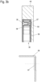
- Figure 3a shows a top view of the end face 43 of the furniture panel 40 with the mounting element 50, in which the fitting 30 is inserted and on which the cover 36 is placed.
- embossings 57 (cf. lower part of Figure 3b ) arranged on which the mounting bolts 53 are fixed.
- the contact points of the fitting 30 on the mounting element 50 are precisely defined by the embossing 57 and it is possible to keep the height tolerance of the structural unit consisting of the mounting element 50 and the fitting 30 within a narrow dimensional range. Any unevenness in the bottom 51 of the mounting element 50 is therefore irrelevant to the overall height.
- Figures 4a and 4b a second exemplary embodiment of a furniture panel 40 with an integrated mounting element 50 is shown.
- Figure 4a shows the arrangement in a side view of the side surface 41 of the furniture panel 40 and Figure 4b in an isometric oblique view.
- a recess 42 is made in the furniture panel 40, in which the mounting element 50 is inserted.
- This in turn has a flat bottom 51 which is folded on three sides, so that side sections 52 are formed. The side sections 52 end flush with the edges of the recess 42.
- Gluing of the mounting element 50 to the furniture panel 40 is preferably provided again for fastening. Reference is made to the alternative or additional fastening methods in connection with the first exemplary embodiment.
- the fitting 30 is not inserted from the side face 41 here, but pushed in from the end face 43 .
- the front opening is corresponding formed in the furniture panel 40 in such a way that the opening cross-section corresponds to the dimensions of the fitting 30 at points of its maximum installation height, so that it can be pushed in from the end face 43 .
- a guide bar 54 is arranged on the lower and on the upper side section 52 .
- the side plates 31, 32 projecting slightly upwards or downwards grip around the sides of the guide webs 54, as a result of which the fitting 30 is fixed in a direction perpendicular to the side face 41 of the furniture panel 40.
- detent springs 55 which are flared inwards and with which the fitting 30 locks in the inserted state.
- Spring elements 56 are also arranged on the rear side section 52 of the mounting element 50, seen in the direction of insertion 6 and 7 is explained.
- the furniture panel 40 with the fitting 30 inserted is shown in a manner analogous to that in FIGS Figures 4a and 4b in the Figures 5a and 5b shown. Again, the fitting 30 is aligned substantially flush with its side panel 31 pointing outwards with the side surface 41 of the furniture panel 40 .
- a cover cf. cover 36 of the first embodiment
- the insertion of the fitting 30 into the mounting element 50 is again shown as an example outside of the furniture panel 40 .
- the side plates 31, 32 are spaced apart from one another by a frame 38.
- the frame 38 runs along at least the upper and lower sides and preferably also along the rear side of the fitting 30 and together with the side plates 31, 32 forms a housing of the fitting 30.
- the frame 38 is offset slightly inwards relative to the side plates 31, 32, so that a U-shaped guide profile is formed in each case, which accommodates the corresponding guide bar 54.
- a locking recess 37 is arranged in the frame 38 at a suitable point, in which the detent spring 55 engages, so that the fitting 30 not only through the guide 54 laterally, but also in view is fixed to the direction of insertion and can no longer be easily removed from the front.
- the inserted state of the fitting 30 in the mounting element 50 is in the 7 played back.
- Next shows the 7 the attachment of a removal tool 60, which has a front handle part 61 and two strip-shaped insertion tongues 62 projecting perpendicularly therefrom and aligned parallel to one another.
- the insertion tongues 62 are inserted adjacent to the frame 38 between the side sections 52 of the mounting plate 50 and the fitting 30 and lever the detent spring 55 out of the detent recess 37.
- the fitting 30 is removed by the in 6 visible spring elements 56 supported.
- the spring elements 56 are tensioned when the fitting 30 is pushed in and spring out after the latching between the locking spring 55 and the locking recess 37 has been released and push the fitting 30 so far in the removal direction that it can then be easily gripped by a user.
- the arrangement shown in the second exemplary embodiment thus also allows the fitting 30 to be replaced when the furniture carcass or piece of furniture is mounted.
- the mounting element 50 can also be produced in several parts, in which case the detent springs 55 and spring elements 56 can be fixed separately from an elastic, resilient material.
Description
Die Erfindung betrifft eine Anordnung einer Möbelplatte und einem Bewegungsbeschlag für bewegbare Möbelteile, wobei die Möbelplatte eine Aussparung und ein integriertes Montageelement zur Aufnahme eines Bewegungsbeschlags aufweist, wobei das Montageelement einen Boden und an zumindest zwei Seiten des Bodens von diesem abstehende Seitenabschnitte aufweist, und wobei das Montageelement in die Aussparung der Möbelplatte eingesetzt ist und sich die Aussparung von einer Seitenfläche und wenigstens einer Stirnseite der Möbelplatte her erstreckt. Dabei ist wenigstens der Boden des Montageelements kraftschlüssig oder stoffschlüssig mit einer Gegenfläche der Aussparung verbunden und das Montageelement weist Mittel zu Befestigung des Bewegungsbeschlags auf, wobei der Bewegungsbeschlag im Hinblick auf die Seitenfläche der Möbelplatte im Wesentlichen vollständig in die Möbelplatte einsetzbar ist, und wobei bewegliche Teile des Bewegungsbeschlags aus einer Stirnseite der Möbelplatte herausfahrbar sind. Die Erfindung betrifft weiterhin einen Möbelkorpus bzw. ein Möbel.The invention relates to an arrangement of a furniture panel and a movement fitting for movable furniture parts, the furniture panel having a recess and an integrated mounting element for receiving a movement fitting, the mounting element having a base and side sections protruding from the base on at least two sides of the base, and the Mounting element is inserted into the recess of the furniture panel and the recess extends from a side surface and at least one end face of the furniture panel. In this case, at least the base of the mounting element is non-positively or materially connected to a mating surface of the recess and the mounting element has means for fastening the movement fitting, with the movement fitting being able to be inserted essentially completely into the furniture panel with regard to the side surface of the furniture panel, and with moving parts of the movement fitting can be moved out of a front side of the furniture panel. The invention also relates to a furniture body or a piece of furniture.
Die Korpusse von Möbeln sind in der Regel aus Möbelplatten gebildet, die auf der Basis von Holz oder einem Holzwerkstoff, beispielsweise einer Spanplatte oder einer mitteldichten oder hochdichten Faserplatte (MDF - Medium Density Fiber, HDF - High Density Fiber), gefertigt sind. Zur Verbindung der Möbelplatten untereinander oder zum gelenkigen Anbinden von bewegbaren Möbelteilen wie Türen oder Klappen werden Verbindungsbeschläge, Bewegungsbeschläge oder sonstige Funktionsbeschläge verwendet, die in diesem Rahmen zusammenfassend als Beschläge bezeichnet werden. Beschläge werden in der Regel aus Kunststoffen und/oder metallischen Werkstoffen gefertigt. Üblicherweise werden insbesondere größere Beschläge auf die Möbelplatten aufgesetzt und mit diesen verschraubt. Sie ragen dann in den Innenraum des Möbelkorpus hinein, wodurch sie bei geschlossener Tür oder Klappe nicht sichtbar sind, jedoch die Optik des Möbelkorpus bei geöffneter Tür oder Klappe beeinträchtigen und das nutzbare Innenvolumen des Möbelkorpus reduzieren.The bodies of furniture are usually formed from furniture boards based on wood or a wood-based material, such as chipboard or medium-density or high-density fiberboard (MDF - Medium Density Fiber, HDF - High Density Fiber), are made. Connection fittings, movement fittings or other functional fittings are used to connect the furniture panels to one another or for the articulated connection of movable furniture parts such as doors or flaps, which are collectively referred to as fittings in this context. Fittings are generally made from plastics and/or metal materials. Larger fittings in particular are usually placed on the furniture panels and screwed to them. They then protrude into the interior of the furniture body, which means that they are not visible when the door or flap is closed, but impair the appearance of the furniture body when the door or flap is open and reduce the usable interior volume of the furniture body.
Bei kleineren Beschlägen ist auch ein Einlassen in eine Bohrung oder Ausnehmung bekannt. Die Druckschrift
Die Druckschrift
Es ist eine Aufgabe der vorliegenden Erfindung, eine Anordnung aus einer Möbelplatte und einem Bewegungsbeschlag so weiterzubilden, dass der Bewegungsbeschlag auf einfache Weise montiert und auch demontiert werden kann.It is an object of the present invention to develop an arrangement made up of a furniture panel and a movement fitting in such a way that the movement fitting can be fitted and also dismantled in a simple manner.
Diese Aufgabe wird durch eine Anordnung und einen Möbelkorpus bzw. ein Möbel mit einer derartigen Anordnung mit den Merkmalen des jeweiligen unabhängigen Anspruchs gelöst. Vorteilhafte Ausgestaltung und Weiterbildungen sind Gegenstand der abhängigen Ansprüche.This object is achieved by an arrangement and a furniture body or a piece of furniture with such an arrangement with the features of the respective independent claim. Advantageous configurations and developments are the subject matter of the dependent claims.
Eine erfindungsgemäße Anordnung der eingangs genannten Art zeichnet sich dadurch aus, dass an dem Montageelement Führungen, insbesondere in der Form von Führungsstegen, angeordnet oder ausgebildet sind, die ein Einschieben des Bewegungsbeschlags parallel zum Boden ermöglichen. Die Führungen können am Boden, aber auch an den Seitenabschnitten angeordnet oder ausgebildet sein. Die Führungen ermöglichen ein Einschieben des Bewegungsbeschlags von der Stirnseite her. So kann ein kassettenförmiges Montageelement verwendet werden, das die Aussparung zur Korpusinnenseite hin verblendet.An arrangement according to the invention of the type mentioned at the outset is characterized in that guides, in particular in the form of guide webs, are arranged or formed on the mounting element, which allow the movement fitting to be pushed in parallel to the floor. The guides can be arranged or formed on the floor, but also on the side sections. The guides allow the movement fitting to be pushed in from the front. A cassette-shaped mounting element can be used, which conceals the recess on the inside of the carcass.
Das Befestigungsmittel kann bereits bei Herstellung der Möbelplatte in diese integriert werden und erlaubt eine Befestigung des Bewegungsbeschlags auf engstem Raum. Durch die kraft- oder stoffschlüssig Verbindung mit einer Gegenfläche der Aussparung hat es eine verstärkende (stabilisierende) Funktion für die Möbelplatte. Aufgrund der Stabilisierung kann die Aussparung (von der Seitenfläche der Möbelplatte aus gesehen) großflächiger und/oder tiefer ausgebildet werden, als es ohne die Stabilisierung der Möbelplatte im Bereich der Aussparung möglich wäre. Der für den Bewegungsbeschlag zur Verfügung stehende Platz innerhalb der Möbelplatte kann so trotz des zusätzlichen Befestigungsmittels effektiv vergrößert werden.The fastening means can already be integrated into the furniture panel when it is being manufactured and allows the movement fitting to be fastened in a very confined space. Through the non-positive or material connection with a counter surface the recess, it has a reinforcing (stabilizing) function for the furniture board. Because of the stabilization, the cutout (seen from the side surface of the furniture panel) can be made larger and/or deeper than would be possible without the stabilization of the furniture panel in the area of the cutout. The space available for the movement fitting within the furniture panel can thus be effectively increased despite the additional fastening means.
Dadurch, dass der Bewegungsbeschlag im Hinblick auf die Seitenfläche der Möbelplatte im Wesentlichen vollständig in die Möbelplatte einsetzbar ist, wird eine Integration des Bewegungsbeschlags in die Möbelplatte erreicht, so dass dieser nicht er nicht oder nur unwesentlich in den Innenraum eines Möbelkorpus hinein ragt. Dabei ist der Ausdruck "im Wesentlichen" so zu verstehen, dass ein eventueller Überstand des Bewegungsbeschlags so klein ist, dass der Bewegungsbeschlag die Gestaltung des Innenraums des Korpus nicht beeinträchtigt. Der Überstand ist bevorzugt kleiner als 3 Millimeter (mm) oder, in relativen Maßen ausgedrückt, bevorzugt kleiner als etwa 10% der Tiefe der Aussparung.The fact that the movement fitting can be inserted essentially completely into the furniture panel with regard to the side surface of the furniture panel means that the movement fitting is integrated into the furniture panel so that it does not protrude or only slightly into the interior of a furniture body. The expression “substantially” is to be understood in such a way that any overhang of the movement fitting is so small that the movement fitting does not impair the design of the interior of the body. The overhang is preferably less than 3 millimeters (mm), or in relative terms, preferably less than about 10% of the depth of the recess.
In einer vorteilhaften Ausgestaltung der Anordnung ist die Aussparung (nachträglich) in die Möbelplatte eingebracht, bevorzugt eingefräst oder eingeprägt. Die Möbelplatte kann so zunächst konventionell z.B. aus Holz oder einem Holzverbundwerkstoff, ohne die Aussparung hergestellt werden. Die Aussparung kann dann nachträglich erstellt werden. Dieses kann bevorzugt von der Seitenfläche her erfolgen. Alternativ kann die Aussparung mit der Möbelplatte zusammen in einem Urformverfahren erstellt werden, z.B. in einem Schäum- oder Gießverfahren.In an advantageous embodiment of the arrangement, the recess is (subsequently) introduced into the furniture panel, preferably milled or embossed. The furniture panel can thus initially be produced conventionally, e.g. from wood or a wood composite material, without the recess. The recess can then be created later. This can preferably be done from the side surface. Alternatively, the recess can be created together with the furniture board in a primary molding process, e.g. in a foaming or casting process.
In einer weiteren vorteilhaften Ausgestaltung der Anordnung weist die Aussparung eine über ihre Fläche konstante Tiefe auf. Insbesondere bei einem Einfräsen der Aussparung stellt dieses eine einfach herzustellende Form der Aussparung dar. Es sind grundsätzlich jedoch auch andere Formen möglich, beispielsweise eine in der Tiefe gestufte Aussparung, wobei die Aussparung in dem Bereich des Bewegungsbeschlags, in dem bewegte Beschlagelemente wie Hebel oder dergleichen angeordnet sind, tiefer ist als in anderen Bereichen.In a further advantageous embodiment of the arrangement, the recess has a constant depth over its area. In particular, when the recess is milled, this represents a form of recess that is easy to produce. In principle, however, other forms are also possible, for example a recess with a stepped depth, the recess being in the area of the movement fitting, in which moving fitting elements such as levers or the like are arranged, is lower than in other areas.
Die Tiefe der Aussparung kann beispielsweise mindestens 14 mm betragen und die Stärke des im Bereich der Aussparung verbleibenden Materials der Möbelplatte kann zwischen etwa 1 und 10 mm betragen.The depth of the recess can be at least 14 mm, for example, and the thickness of the material of the furniture panel remaining in the region of the recess can be between approximately 1 and 10 mm.
In einer weiteren vorteilhaften Ausgestaltung der Anordnung ist das Montageelement in die Aussparung stoffschlüssig eingeklebt. Eine Verklebung ist platzsparend und kann auch bei einer geringen verbleibenden Materialstärke der Möbelplatte in dem Bereich der Aussparung umgesetzt werden. Bei einer vollflächigen oder nahezu vollflächigen Verklebung des Bodens des Montageelements mit der Möbelplatte kann im Bereich der Aussparung die Möbelplatte eine besonders geringe Materialstärke aufweisen, wodurch ein maximal tiefer Einbauraum für den Bewegungsbeschlag geschaffen wird.In a further advantageous embodiment of the arrangement, the mounting element is adhesively bonded into the recess. Bonding saves space and can be implemented even if the remaining material thickness of the furniture board is small in the area of the recess. If the bottom of the mounting element is glued to the furniture panel over the entire surface or almost over the entire surface, the material thickness of the furniture board can be particularly low in the area of the cutout, creating the maximum possible depth of installation space for the movement fitting.
Alternativ oder zusätzlich zur Verklebung kann der Boden mehrere Formelemente, z.B. Spitzen (Spikes), aufweisen, die in die Gegenfläche der Aussparung einpressbar sind und durch die ebenfalls eine stabilisierende Verbindung geschaffen wird.As an alternative or in addition to gluing, the base can have several shaped elements, e.g. spikes, which can be pressed into the opposite surface of the recess and which also create a stabilizing connection.
In einer weiteren vorteilhaften Ausgestaltung der Anordnung ist die Stirnseite mit der Aussparung mit einer Schmalseitenbeschichtung z.B. einem Kantenumleimer versehen. Bevorzugt ist eine Stirnseite des Bodens zu der mit der Aussparung versehenen Stirnseite hin ausgerichtet und die Stirnseite des Bodens ist - bevorzugt im Wesentlich vollständig - von der Schmalseitenbeschichtung verdeckt.In a further advantageous embodiment of the arrangement, the end face with the recess is provided with a coating on the narrow side, e.g. an edge band. An end face of the base is preferably aligned with the end face provided with the recess and the end face of the base is—preferably essentially completely—covered by the coating on the narrow side.
In einer weiteren vorteilhaften Ausgestaltung der Anordnung ist das Montageelement aus einem metallischen Werkstoff hergestellt, wobei ein Elastizitätsmodul des metallischen Werkstoffs um mindestens einen Faktor 10 höher ist als ein Elastizitätsmodul eines Möbelplattenwerkstoffs bzw. Möbelplattenverbundwerkstoffs. Ein derartig großer Unterschied in dem Elastizitätsmodul (E-Modul), insbesondere im Hinblick auf eine Zug-Belastung, ermöglicht es, eine Materialschwächung der Möbelplatte durch die Aussparung mit einem relativ dünnen Boden des Montageelements auszugleichen. Auf diese Weise wird Platz für den Bewegungsbeschlag geschaffen, ohne dass die Festigkeit bzw. Stabilität der Möbelplatte abnimmt. Die E-Module von typischen Werkstoffen bzw. Verbundwerkstoffen von Möbelplatten liegen im Bereich von etwa 1000 bis etwa 6500 N/mm2 (Newton pro Quadratmillimeter).In a further advantageous embodiment of the arrangement, the mounting element is made of a metallic material, with a modulus of elasticity of the metallic material being at least a factor of 10 higher than a modulus of elasticity of a furniture panel material or furniture panel composite material. Such a large difference in the modulus of elasticity (E-modulus), in particular with regard to a tensile load, makes it possible to compensate for a material weakening of the furniture panel due to the recess with a relatively thin base of the mounting element. In this way, space is created for the movement fitting without reducing the strength or stability of the furniture panel. The moduli of elasticity of typical materials or composite materials of furniture panels are in the range of about 1000 to about 6500 N/mm 2 (Newton per square millimeter).
In einer weiteren vorteilhaften Ausgestaltung weist die Möbelplatte der Anordnung eine Abdeckung für den in das Montageelement eingesetzten Bewegungsbeschlag auf, der bis zu maximal 3 mm über die Seitenfläche überstehen kann. Eine solche Abdeckung ist optisch unauffällig und nicht störend. Durch den geringen Überstand kann das von der Aussparung bereitgestellte Volumen maximal vom Bewegungsbeschlag beansprucht werden.In a further advantageous embodiment, the furniture panel of the arrangement has a cover for the movement fitting used in the mounting element, which can protrude up to a maximum of 3 mm over the side surface. Such a cover is visually inconspicuous and not disturbing. Due to the small overhang, the maximum volume provided by the recess can be used by the movement fitting.
In einer weiteren vorteilhaften Ausgestaltung der Anordnung sind die Mittel zur Befestigung des Bewegungsbeschlags an dem Boden angebracht. Die Mittel zur Befestigung des Bewegungsbeschlags können beispielsweise senkrecht von dem Boden abstehende Montagebolzen sein, auf die der Bewegungsbeschlag mit entsprechenden Montagebohrungen aufgesteckt wird. Dabei können die Montagebolzen jeweils eine Bohrung mit Innengewinde aufweisen, in die Montageschrauben einschraubbar sind. Auf diese Weise kann der Bewegungsbeschlag einfach von der korpusinnenseitigen Seite der Möbelplatte in die Aussparung eingesetzt und befestigt werden.In a further advantageous embodiment of the arrangement, the means for fastening the movement fitting are attached to the floor. The means for fastening the movement fitting can, for example, be mounting bolts which protrude perpendicularly from the floor and onto which the movement fitting is fitted with corresponding mounting bores. The mounting bolts can each have a bore with an internal thread into which mounting screws can be screwed. In this way, the movement fitting can be easily inserted into the recess and fastened from the inside of the furniture panel on the carcass side.
In einer weiteren vorteilhaften Ausgestaltung der Anordnung weist der Boden mindestens eine Prägung auf, an der der Bewegungsbeschlag anliegt. Durch die mindestens Prägung ist die Anlagestelle bzw. sind die Anlagestellen des Bewegungsbeschlags am Montageelement exakt definiert und es ist ermöglicht, eine Höhentoleranz der Baueinheit bestehend aus Montageelement und Bewegungsbeschlag in einem engen Maßbereich zu halten. Mögliche Unebenheiten des Bodens des Montageelements spielen dadurch bezüglich der Gesamthöhe keine Rolle mehr.In a further advantageous embodiment of the arrangement, the base has at least one embossing on which the movement fitting rests. Due to the at least embossing, the contact point or the contact points of the movement fitting on the mounting element are precisely defined and it is possible to keep a height tolerance of the structural unit consisting of mounting element and movement fitting within a narrow dimensional range. Any unevenness in the bottom of the mounting element is therefore no longer relevant to the overall height.
Bevorzugt sind dabei Rastmittel vorgesehen, durch die der Bewegungsbeschlag mit dem Montageelement verrastet. Die Rastmittel können bevorzugt Rastfedern sein, die an dem Boden und/oder an den Seitenabschnitten und/oder die an dem Bewegungsbeschlag angeordnet oder ausgebildet sind. Die Rastfedern können so angeordnet und ausgebildet sein, dass durch ein Einführen einer Einsteckzunge eines Entnahmewerkzeugs in einen Spalt zwischen dem Montageelement und dem Bewegungsbeschlag die Verrastung des Bewegungsbeschlags gelöst wird. So kann der Bewegungsbeschlag ggf. zur Reparatur oder Wartung oder zum Austausch auch wieder entnommen werden.In this case, locking means are preferably provided, by means of which the movement fitting locks with the mounting element. The latching means can preferably be latching springs which are arranged or formed on the base and/or on the side sections and/or on the movement fitting. The detent springs can be arranged and designed in such a way that the locking of the movement fitting is released by inserting an insertion tongue of a removal tool into a gap between the mounting element and the movement fitting. In this way, the movement fitting can also be removed again if necessary for repair or maintenance or for replacement.
Ein erfindungsgemäßer Möbelkorpus oder ein erfindungsgemäßes Möbel hat eine Wand, insbesondere Seitenwand, die eine derartige Anordnung einer Möbelplatte mit integriertem Montageelement und einem Bewegungsbeschlag aufweist. Es ergeben sich die im Zusammenhang mit der Anordnung geschilderten Vorteile.A furniture body according to the invention or a piece of furniture according to the invention has a wall, in particular a side wall, which has such an arrangement of a furniture panel with an integrated mounting element and a movement fitting. The advantages described in connection with the arrangement result.
Die Erfindung wird nachfolgend anhand von Ausführungsbeispielen mit Hilfe von Figuren näher erläutert.The invention is explained in more detail below on the basis of exemplary embodiments with the aid of figures.
Die Figuren zeigen:
- Fig. 1
- ein Möbel mit einer Seitenwand mit integriertem Montagelement für einen Bewegungsbeschlag;
- Fig. 2
- eine isometrische Explosionsdarstellung eines ersten Ausführungsbeispiels einer Anordnung einer Möbelplatte mit Montageelement und eines Bewegungsbeschlags;
- Fig. 3a
- eine stirnseitige Ansicht der Möbelplatte gemäß
Fig. 2 ; - Fig. 3b
- eine Schnittdarstellung eines Abschnitts der Möbelplatte gemäß
Fig. 2 - Fig. 4a, b
- eine isometrische Schrägansicht und eine Seitenansicht einer Möbelplatte mit Montageelement eines zweiten Ausführungsbeispiels;
- Fig. 5a, b
- wie
Fig. 4a, b mit eingesetztem Bewegungsbeschlag; - Fig. 6
- eine isometrische Darstellung eines Montageelements mit teileingeschobenem Bewegungsbeschlag; und
- Fig. 7
- eine isometrische Ansicht des Montageelements 50 mit eingeschobenem Bewegungsbeschlag gemäß
Fig. 6 sowie einem Entnahmewerkzeug.
- 1
- a piece of furniture with a side wall with an integrated mounting element for a movement fitting;
- 2
- an isometric exploded view of a first embodiment of an arrangement of a furniture panel with mounting element and a movement fitting;
- Figure 3a
- according to an end view of the furniture panel
2 ; - Figure 3b
- a sectional view of a portion of the furniture panel according to FIG
2 - Fig. 4a, b
- an isometric oblique view and a side view of a furniture panel with mounting element of a second embodiment;
- Fig. 5a, b
- How
Fig. 4a, b with inserted movement fitting; - 6
- an isometric representation of a mounting element with a partially inserted movement fitting; and
- 7
- an isometric view of the mounting
element 50 with the movement fitting pushed in according to FIG6 and a removal tool.
In allen Figuren kennzeichnen gleiche Bezugszeichen gleiche oder gleichwirkende Elemente. Aus Gründen der Übersichtlichkeit ist in den Figuren nicht jedes Element in allen Figuren mit einem Bezugszeichen versehen.In all figures, the same reference symbols identify the same or equivalent elements. For reasons of clarity, not every element in all figures is provided with a reference number in the figures.
In der Beschreibung beziehen sich Begriffe wie oben, unten, links, rechts ausschließlich auf die in den jeweiligen Figuren gewählte beispielhafte Darstellung. Die Begriffe vorne und hinten sind auf eine Ausrichtung des Möbelkorpus bezogen, wobei die vordere Seite die offene und dem Benutzer in der Regel zugewandte Seite des Möbelkorpus kennzeichnet.In the description, terms such as top, bottom, left, right refer exclusively to the exemplary representation selected in the respective figures. The terms front and rear refer to an orientation of the furniture body, with the front side identifying the open side of the furniture body that generally faces the user.
Der Oberschrank umfasst einen Möbelkorpus 10 mit einem Unterboden 11 und einem Oberboden 12 sowie zwei Seitenwänden 13. Eine Rückwand ist bevorzugt unter anderem aus Stabilitätsgründen vorhanden, in diesem Ausführungsbeispiel aber nicht sichtbar.The upper cabinet comprises a
Der Möbelkorpus 10 ist nach vorne offen, um Zugang zum Innenraum des Schrankes zu erhalten. Es ist eine Klappenanordnung 20 mit einer in diesem Beispiel einteiligen Klappe 21 vorgesehen, um die Öffnung des Möbelkorpus 10 verschließen zu können. Die einteilige Klappe 21 ist entlang ihrer oberen horizontalen Seitenkante schwenkbar gelagert. Zu diesem Zweck sind Bewegungsbeschläge 30 vorgesehen, die mit einem Hebelwerk 33 im oberen Bereich der einteiligen Klappe 21 mit dieser verbunden sind.The
Die Bewegungsbeschläge 30, nachfolgend abgekürzt auch als Beschläge 30 bezeichnet, sind dabei (bis auf das in der dargestellten Öffnungsstellung ausgefahrene Hebelwerk 33) versenkt in der jeweiligen Seitenwand 13 angeordnet. Im geschlossenen Zustand der Klappe 21 ist das Hebelwerk 33 ggf. bis auf Montageelemente zur Verbindung mit der Klappe 21 vollständig in die Seitenwand 13 eingefahren. Der Bereich innerhalb der Seitenwand 13, in dem sich der Beschlag 30 befindet, ist in der
Die Seitenwand 13 zeichnet sich durch Seitenflächen aus, die idealerweise zumindest an der Außenseite des Möbelkorpus 10 über ihre gesamte Fläche eine durchgängig gleiche Oberflächenbeschaffenheit aufweisen. Die Oberfläche der Seitenflächen kann durch verschiedene Muster, Oberflächenbeschaffenheit oder verschiedene Farben Designeffekte erzeugen. An der zum Innenraum des Möbelkorpus 10 weisenden jeweiligen inneren Seitenfläche der Seitenwände 13 ist die Abdeckung 36 bevorzugt bündig mit der sonstigen Oberfläche der Seitenwand 13. Sie kann optisch angepasst sein oder sich auch bewusst optisch absetzen in Relation zur Oberfläche der Seitenwand 13.The side wall 13 is characterized by side surfaces which ideally have the same surface quality throughout, at least on the outside of the
Anmeldungsgemäß sind die Seitenwände 13 aus Möbelplatten 40 aufgebaut, die ein integriertes Montageelement 50 zur Befestigung des Beschlags 30 aufweisen. Die Möbelplatten 40 und damit die Seitenwände 13 weisen eine Stirnseite 43 auf, die im Bereich des Beschlags 30 eine Öffnung aufweist, in die das Hebelwerk 33 des Beschlags 30 eintaucht bzw. aus der das Hebelwerk 33 ausfährt. Im geschlossenen Zustand der Klappenanordnung 20 ist das Hebelwerk 33 bis auf eventuelle Befestigungsmittel, mit dem es mit der hier einteiligen Klappe 21 verbunden ist, vollständig in die Öffnung eingetaucht.According to the application, the side walls 13 are constructed from
Der Aufbau einer für die Seitenwände 13 geeigneten Möbelplatte 40 ist im Zusammenhang mit den
Die Möbelplatte 40 ist in der Regel aus Holz oder einem Holzwerkstoff (Spanplatte, MDF, HDF) oder auch einem Holz/Kunststoff-Verbundwerkstoff gefertigt. In alternativen Ausgestaltungen können auch Steinplatten als Möbelplatten verwendet werden.The
Die Möbelplatte 40 weist eine von einer Seitenfläche 41 her eingebrachte Aussparung 42 auf, die zumindest abschnittsweise auch zu einer Stirnseite 43 der Möbelplatte 40 hin geöffnet ist. Durch die Öffnung in der Stirnseite 43 tritt das Hebelwerk 33 aus.The
Die Montageplatte 50 ist in die Aussparung 42 eingesetzt und mit der Möbelplatte 40 verbunden, insbesondere verklebt. Das Montageelement 50 weist einen rechteckigen ebenen Boden 51 auf und drei Seitenabschnitte 52. Die zur Stirnseite 43 der Möbelplatte 40 weisende Seite verbleibt offen. Der Boden 51 ist bevorzugt einstückig mit den Seitenabschnitten 52 ausgebildet und kann beispielsweise aus Stahlblech gefertigt sein, wobei die Seitenabschnitte 52 von dem Boden 51 abgekantet sind. Das Montageelement 50 kann so beispielsweise kostengünstig als Stanzbiegeteil gefertigt werden.The mounting
Die Abmessungen des Montageelements 50 entsprechen der Kontur der Aussparung 42, so dass das Montageelement 50 von der Seitenfläche 41 der Möbelplatte 40 her möglichst passgenau in die Aussparung 42 eingesetzt werden kann. Bereits durch das passgenaue Einsetzen können auf den Beschlag 30 wirkende Kräfte über das Montageelement 50 gut in die Möbelplatte 40 eingeleitet werden. Zudem sind zusätzlich Verbindungsmittel vorgesehen, um das Montageelement 50 an der Möbelplatte 40 zu befestigen. Vorteilhaft kann das Montageelement 50 in die Aussparung 42 eingeklebt werden, wobei sich insbesondere der großflächige Boden 51 für eine Verklebung eignet. Durch eine derartige Verklebung wird nicht nur das Montageelement 50 fixiert, sondern auch der Boden der Aussparung 42, der unter Umständen aus einer nur wenige Millimeter (mm) starken verbleibenden Schicht der Möbelplatte 40 besteht, stabilisiert. Eine Verklebung kann zusätzlich an den Außenflächen der Seitenabschnitte 52 erfolgen. An diesen Stellen können auch Schraubverbindungen vorgesehen sein, bei denen Schrauben durch die Seitenabschnitte 52 des Montagelements 50 in das Kernmaterial der Möbelplatte 40 eingeschraubt werden.The dimensions of the mounting
Auf dem Boden 51 sind zudem Montagebolzen 53 angeordnet, beispielsweise aufgeschweißt in einem Punktschweißprozess oder durch Öffnungen des Bodens 51 gesteckt und mit dieser verbördelt. Der einzusetzende Beschlag 30 weist an den Positionen der Montagebolzen 53 Montagebohrungen 34 auf, und wird entsprechend mit diesen Montagebohrungen 34 auf die Montagebolzen 53 aufgesteckt. Die Montagebolzen 53 sind im dargestellten Ausführungsbeispiel mit einem zentralen Innengewinde versehen, in das Montageschrauben 35 geschraubt werden, die entsprechend die Seitenplatte 31 und damit den Beschlag 30 auf den Montagebolzen 53 sichern.Mounting
Auf den Beschlag 30 wird zur Abdeckung die bereits im Zusammenhang mit der
Die Aussparung 42 der Möbelplatte 40 kann so tief ausgebildet sein, dass sie den Beschlag 30, ggf. mit der Abdeckung 36, vollständig aufnimmt. Vorteilhaft ist dann der Bereich des Beschlags 30, ggf. mit der Abdeckung 36, bündig zur sonstigen Oberfläche der Seitenfläche 41. Es entsteht - insbesondere mit aufgesetzter Abdeckung 36 - eine optisch nahezu homogene Fläche. Dennoch kann nach einem Abnehmen der Abdeckung 36 und einem Lösen der Montageschrauben 35 der Beschlag 30 bei montierten Möbel nach innen zum Innenraum des Möbelkorpus hin entnommen werden, beispielsweise um ihn bei einem eventuellen Defekt oder bei Verschleiß austauschen zu können.The
In dem oberen Teil der
An dem Boden 51 des Montageelements 50 sind Prägungen 57 (vgl. unterer Teil der
In den
Wie bei dem zuvor gezeigten Ausführungsbeispiel ist in die Möbelplatte 40 eine Aussparung 42 eingebracht, in die das Montagelement 50 eingesetzt ist. Dieses weist wiederum einen ebenen Boden 51 auf, der an drei Seiten abgekantet ist, so dass Seitenabschnitte 52 gebildet sind. Die Seitenabschnitte 52 enden bündig mit den Kanten der Aussparung 42.As in the previously shown embodiment, a
Zur Befestigung ist bevorzugt wieder ein Verkleben des Montageelements 50 mit der Möbelplatte 40 vorgesehen. Auf die in Zusammenhang mit dem ersten Ausführungsbeispiel alternativen oder zusätzlichen Befestigungsmethoden wird verwiesen.Gluing of the mounting
Im Unterschied zum ersten Ausführungsbeispiel ist vorliegend ein Einsetzen des Beschlags 30 nicht von der Seitenfläche 41 her vorgesehen, sondern ein Einschieben von der Stirnseite 43 her. Entsprechend ist die stirnseitige Öffnung in der Möbelplatte 40 so ausgebildet, dass der Öffnungsquerschnitt den Abmessungen des Beschlags 30 an Stellen seiner maximalen Einbauhöhe entspricht, so dass dieser von der Stirnseite 43 her eingeschoben werden kann.In contrast to the first exemplary embodiment, the fitting 30 is not inserted from the
Zur Befestigung des Beschlags 30 in dem Montagelement 50 ist an dem unteren und an dem oberen Seitenabschnitt 52 jeweils ein Führungssteg 54 angeordnet. Beim Einschieben des Beschlags 30 umgreifen die nach oben bzw. unten leicht überstehenden Seitenplatten 31, 32 die Seiten der Führungsstege 54, wodurch der Beschlag 30 in einer Richtung senkrecht zur Seitenfläche 41 der Möbelplatte 40 festgelegt ist. Weiterhin sind im gezeigten Beispiel vor (in Einschubrichtung des Beschlags 30 gesehen) den Führungsstegen 54 nach innen ausgestellte Rastfedern 55 angeordnet, mit denen der Beschlag 30 im eingeschobenen Zustand verrastet. An dem in Einschubrichtung gesehen hinteren Seitenabschnitt 52 des Montageelements 50 sind zudem Federelemente 56 angeordnet, deren Funktion nachfolgend in Zusammenhang mit den
Die Möbelplatte 40 mit eingeschobenem Beschlag 30 ist in analoger Darstellungsweise wie in den
In
An der oberen und der hier nicht sichtbaren unteren Seite ist der Rahmen 38 gegenüber den Seitenplatten 31, 32 leicht nach innen versetzt, so dass jeweils ein u-förmiges Führungsprofil gebildet wird, das den entsprechenden Führungssteg 54 aufnimmt. Weiter ist in dem Rahmen 38 an geeigneter Stelle eine Rastvertiefung 37 angeordnet, in die die Rastfeder 55 einrastet, so dass der Beschlag 30 nicht nur durch die Führung 54 seitlich, sondern auch im Hinblick auf die Einschubrichtung festgelegt ist und nicht mehr ohne weiteres nach vorne entnommen werden kann.On the upper side and the lower side (not visible here), the
Der eingeschobene Zustand des Beschlags 30 in dem Montageelement 50 ist in der
Das Entnehmen des Beschlags 30 wird durch die in
Auch die im zweiten Ausführungsbeispiel gezeigte Anordnung erlaubt somit einen Austausch des Beschlags 30 bei montiertem Möbelkorpus oder Möbel.The arrangement shown in the second exemplary embodiment thus also allows the fitting 30 to be replaced when the furniture carcass or piece of furniture is mounted.
Alternativ ist für das Montageelement 50 auch die Verwendung anderer Materialien wie beispielsweise Kunststoff oder Leichtmetall möglich. Das Montageelement 50 kann dabei auch mehrteilig hergestellt sein, wobei die Rastfedern 55 und Federelemente 56 aus einem elastischen federnden Material separat festgelegt sein können.Alternatively, other materials such as plastic or light metal can also be used for the mounting
- 1010
- Möbelkorpusfurniture body
- 1111
- Unterbodenunderbody
- 1212
- Oberbodentopsoil
- 1313
- SeitenwandSide wall
- 2020
- Klappenanordnungflap arrangement
- 2121
- einteilige Klappeone-piece flap
- 3030
- Beschlagfitting
- 31,3231:32
- Seitenplatteside plate
- 3333
- Hebelwerklever mechanism
- 3434
- Montagebohrungmounting hole
- 3535
- Montageschraubemounting screw
- 3636
- Abdeckungcover
- 3737
- Rastvertiefungdetent recess
- 3838
- RahmenFrame
- 4040
- Möbelplattefurniture board
- 4141
- Seitenflächeside face
- 4242
- Aussparungrecess
- 4343
- Stirnseiteface
- 5050
- Montageelementmounting element
- 5151
- BodenFloor
- 5252
- Seitenabschnittside section
- 5353
- Montagebolzenmounting bolts
- 5454
- Führungsstegguide bar
- 5555
- Rastfederdetent spring
- 5656
- Federelementspring element
- 5757
- Prägungembossing
- 6060
- Entnahmewerkzeugremoval tool
- 6161
- Griffteilhandle part
- 6262
- Einsteckzungeinsertion tongue
Claims (21)
- Arrangement of a furniture panel (40) and movement fitting (30) for movable furniture parts, wherein the furniture panel (40) has a recess (42) and an integrated assembly element (50) for accommodating the movement fitting (30), wherein the assembly element (50) comprises a base (51) and lateral portions (52) protruding therefrom on at least two sides of the base (51), and wherein the assembly element (50) is inserted into the recess (42) of the furniture panel (40), and the recess (42) extends from a lateral surface (41) and at least one end face (43) of the furniture panel (40), wherein at least the base (51) of the assembly element (50) is connected in a force-locked or materially-bonded manner to an opposing surface of the recess (42) and the assembly element (50) comprises means for fastening the movement fitting (30), wherein the movement fitting (30) is insertable essentially completely into the furniture panel (40), and wherein movable parts of the movement fitting (30) are extendable out of an end face (43) of the furniture panel, wherein guides are arranged or formed on the assembly element (50) which enable the movement fitting (30) to be pushed in parallel to the base (51).
- Arrangement according to Claim 1, in which the recess (42) is introduced, preferably is milled or embossed in.
- Arrangement according to Claim 1, in which the recess (42) is originally formed with the furniture panel (40).
- Arrangement according to any one of Claims 1 to 3, in which the recess (42) has a constant depth over its area.
- Arrangement according to any one of Claims 1 to 4, in which the assembly element (50) is adhesively bonded in the recess (42).
- Arrangement according to any one of Claims 1 to 5, in which the base (51) comprises multiple shaped elements, for example, spikes, which can be pressed into the opposing surface of the recess (42).
- Arrangement according to any one of Claims 1 to 6, in which the end face (43) having the recess (42) is provided with a narrow side coating, for example, an edge veneer.
- Arrangement according to Claim 7, in which an end face of the base (51) is aligned with the end face (43) provided with the recess (42), wherein the end face of the base (51) is concealed by the narrow side coating.
- Arrangement according to any one of Claims 1 to 8, in which the assembly element (50) is produced from a metallic material, wherein a modulus of elasticity of the metallic material is higher by at least a factor of 10 than a modulus of elasticity of a furniture panel material or furniture panel composite material, in order to compensate for a material weakening due to the recess (42).
- Arrangement according to any one of Claims 1 to 9, in which the furniture panel (40) comprises a cover (36) for the movement fitting (30) inserted into the assembly element (50).
- Arrangement according to Claim 10, in which the cover (36) protrudes in a range of 0 mm to 3 mm from the lateral surface (41).
- Arrangement according to any one of Claims 1 to 11, in which the means for fastening the movement fitting (30) are attached on the base (51).
- Arrangement according to Claim 12, in which the means for fastening the movement fitting (30) are assembly bolts (53) protruding perpendicularly from the base (51), onto which the movement fitting (30) is placed using assembly holes (34).
- Arrangement according to Claim 13, in which the assembly bolts (53) comprise a hole having internal thread, into which assembly screws (35) can be screwed.
- Arrangement according to any one of Claims 1 to 14, in which the base (51) comprises at least one embossment (57).
- Arrangement according to any one of Claims 1 to 15, wherein the guides are in the form of guide webs (54).
- Arrangement according to any one of Claims 1 to 16, in which the guides are arranged or formed on the lateral portions (52).
- Arrangement according to any one of Claims 1 to 17, in which catch means are provided to lock the movement fitting (30) with the assembly element (50).
- Arrangement according to Claim 18, in which the catch means are catch springs (55), which are arranged or formed on the base (51) and/or on the lateral portions (52) and/or on the movement fitting (30).
- Arrangement according to Claim 19, in which the catch springs (55) are arranged and formed such that the locking of the movement fitting (30) is disengaged by an insertion of an insertion tongue (62) of a removal tool (60) into a gap between the assembly element (50) and the movement fitting (30).
- A furniture body (10) or item of furniture having a wall, in particular a side wall (13), which comprises an arrangement of a furniture panel (40) having integrated assembly element (50) and a movement fitting (30) according to any one of Claims 1 to 20.
Applications Claiming Priority (2)
| Application Number | Priority Date | Filing Date | Title |
|---|---|---|---|
| DE102018100206.8A DE102018100206A1 (en) | 2018-01-05 | 2018-01-05 | Furniture panel with integrated mounting element for a motion fitting and furniture body and furniture with such a furniture plate |
| PCT/EP2019/050090 WO2019134936A1 (en) | 2018-01-05 | 2019-01-03 | Furniture panel with integrated assembly element for a movement fitting, furniture body, and furniture comprising such a furniture panel |
Publications (2)
| Publication Number | Publication Date |
|---|---|
| EP3735152A1 EP3735152A1 (en) | 2020-11-11 |
| EP3735152B1 true EP3735152B1 (en) | 2023-06-14 |
Family
ID=64959366
Family Applications (1)
| Application Number | Title | Priority Date | Filing Date |
|---|---|---|---|
| EP19700047.4A Active EP3735152B1 (en) | 2018-01-05 | 2019-01-03 | Arrangement of a furniture panel and a movement fitting with integrated assembly element for the movement fitting, furniture body, and furniture comprising such a furniture panel |
Country Status (4)
| Country | Link |
|---|---|
| EP (1) | EP3735152B1 (en) |
| CN (1) | CN111556721B (en) |
| DE (2) | DE102018100206A1 (en) |
| WO (1) | WO2019134936A1 (en) |
Families Citing this family (6)
| Publication number | Priority date | Publication date | Assignee | Title |
|---|---|---|---|---|
| DE102017108197A1 (en) * | 2017-04-18 | 2018-10-18 | Hettich-Oni Gmbh & Co. Kg | Quarter turn actuator and furniture |
| IT201900013284A1 (en) * | 2019-07-30 | 2021-01-30 | Veneta Cucine S P A | FURNITURE ELEMENT EQUIPPED WITH DOOR WITH HIDDEN DRIVE MECHANISM |
| DE102020125759B4 (en) | 2020-10-01 | 2024-03-21 | ambigence GmbH & Co. KG | Furniture component |
| AT524364B1 (en) * | 2020-11-12 | 2024-01-15 | Blum Gmbh Julius | Furniture fitting with adjustable mounting position of a cover cap |
| CN112530128B (en) * | 2020-12-03 | 2022-03-18 | 国网山东省电力公司电力科学研究院 | Cable tunnel fire prevention early warning inspection system and inspection method |
| AT525449B1 (en) * | 2021-12-03 | 2023-04-15 | Blum Gmbh Julius | Wall and method of making a wall for a furniture body |
Citations (3)
| Publication number | Priority date | Publication date | Assignee | Title |
|---|---|---|---|---|
| DE202008015732U1 (en) * | 2008-11-27 | 2010-04-15 | Hettich-Heinze Gmbh & Co. Kg | Fitting for fixing a lightweight board |
| DE102015108694A1 (en) * | 2014-06-19 | 2015-12-24 | Ernestomeda S.P.A. | Opening mechanism for furniture doors and furniture equipped with this mechanism |
| WO2018158158A1 (en) * | 2017-02-28 | 2018-09-07 | ambigence GmbH & Co. KG | Wall of a basic furniture structure, method for producing such a wall, and basic furniture structure or piece of furniture having such a wall |
Family Cites Families (15)
| Publication number | Priority date | Publication date | Assignee | Title |
|---|---|---|---|---|
| CH463998A (en) * | 1966-05-13 | 1968-10-15 | Guenter & Co Oni Metall | Flap hinge |
| FR2404607A1 (en) * | 1977-09-29 | 1979-04-27 | Deknudt Frans | Clip for supporting pane of glass - has rectangular flanged clip fitted into slot in glass and secured with adhesive |
| FR2438147A1 (en) * | 1978-10-04 | 1980-04-30 | Chereau Jean | IMPROVED RECESSED HINGE |
| JPH095598A (en) * | 1995-06-22 | 1997-01-10 | Sumitomo Electric Ind Ltd | Connection part structure of pneumatic sending type pipe for optical fiber |
| DE102005057150A1 (en) * | 2005-11-30 | 2007-06-06 | BSH Bosch und Siemens Hausgeräte GmbH | Refrigerator or freezer with reinforcement frame |
| DE202006004873U1 (en) * | 2006-03-28 | 2006-06-01 | MEPLA-WERKE LAUTENSCHLäGER GMBH & CO. KG | Hinge for a swing flap/door at furniture, with a joint mechanism, has clamping pads with a radial sliding movement at the two mounting sections to be extended into recesses on installation |
| DE202007015604U1 (en) * | 2007-11-09 | 2009-03-26 | Hettich-Heinze Gmbh & Co. Kg | Connection fitting for lightweight panels |
| DE202008015728U1 (en) * | 2008-11-27 | 2010-04-15 | Hettich-Heinze Gmbh & Co. Kg | fitting |
| EP2530227B1 (en) * | 2011-05-31 | 2013-05-29 | Provex Industrie GmbH | Flush hinge for glass elements |
| CN102318966B (en) * | 2011-09-22 | 2013-10-09 | 伍志勇 | Buffering structure of drawer |
| FR3023331B1 (en) * | 2014-07-01 | 2017-03-10 | Ludovic Charlemagne | MULTIFUNCTION ATTACHMENT SYSTEM AND FURNITURE COMPRISING IT |
| JP2016024434A (en) * | 2014-07-24 | 2016-02-08 | 株式会社リコー | Exfoliation structure of pasting member from exterior member and image forming device |
| DE202014105730U1 (en) | 2014-11-27 | 2016-03-02 | Grass Gmbh & Co. Kg | Wall element of a piece of furniture and furniture with such a wall element |
| DE102015113427A1 (en) * | 2015-08-14 | 2017-02-16 | Form Orange Produktentwicklung | Closet, in particular kitchen closet |
| CN206510633U (en) * | 2016-12-26 | 2017-09-22 | 公安海警学院 | English teaching blackboard |
-
2018
- 2018-01-05 DE DE102018100206.8A patent/DE102018100206A1/en active Pending
-
2019
- 2019-01-03 DE DE202019005313.1U patent/DE202019005313U1/en active Active
- 2019-01-03 WO PCT/EP2019/050090 patent/WO2019134936A1/en unknown
- 2019-01-03 EP EP19700047.4A patent/EP3735152B1/en active Active
- 2019-01-03 CN CN201980007239.2A patent/CN111556721B/en active Active
Patent Citations (3)
| Publication number | Priority date | Publication date | Assignee | Title |
|---|---|---|---|---|
| DE202008015732U1 (en) * | 2008-11-27 | 2010-04-15 | Hettich-Heinze Gmbh & Co. Kg | Fitting for fixing a lightweight board |
| DE102015108694A1 (en) * | 2014-06-19 | 2015-12-24 | Ernestomeda S.P.A. | Opening mechanism for furniture doors and furniture equipped with this mechanism |
| WO2018158158A1 (en) * | 2017-02-28 | 2018-09-07 | ambigence GmbH & Co. KG | Wall of a basic furniture structure, method for producing such a wall, and basic furniture structure or piece of furniture having such a wall |
Also Published As
| Publication number | Publication date |
|---|---|
| WO2019134936A1 (en) | 2019-07-11 |
| CN111556721B (en) | 2022-05-13 |
| DE202019005313U1 (en) | 2020-03-04 |
| CN111556721A (en) | 2020-08-18 |
| DE102018100206A1 (en) | 2019-07-11 |
| EP3735152A1 (en) | 2020-11-11 |
Similar Documents
| Publication | Publication Date | Title |
|---|---|---|
| EP3735152B1 (en) | Arrangement of a furniture panel and a movement fitting with integrated assembly element for the movement fitting, furniture body, and furniture comprising such a furniture panel | |
| EP3589161B1 (en) | Item of furniture and wall element for an item of furniture | |
| EP3589164B1 (en) | Wall of a furniture body, method for producing such a wall, and furniture body or furniture comprising such a wall | |
| EP3150083A1 (en) | Device for angularly connecting and locking two panels, in particular furniture panels | |
| WO2009103571A2 (en) | Fitting for fixing a lightweight building board | |
| EP3589165A1 (en) | Wall for a furniture carcass, method for producing such a wall, and furniture carcass comprising such a wall | |
| DE102009005596B4 (en) | Furniture fittings for lightweight panels, in particular honeycomb panels | |
| WO2018158154A1 (en) | Item of furniture having an attachable plate-shaped composite element with integ rated fitting | |
| WO2019134938A1 (en) | Method for integrating an assembly element for a movement fitting into a furniture panel, and furniture panel with integrated assembly element | |
| EP1895067A1 (en) | Device for actuating a WC tank mounted flush with the wall with dual amount flushing system | |
| WO2010083916A1 (en) | Fastening arrangement for mounting a wall shelf | |
| WO2020030602A1 (en) | Wall for a piece of furniture, method for producing such a wall, and basic furniture structure or piece of furniture having such a wall | |
| DE102007044875A1 (en) | Plate-shaped component | |
| EP2105065A1 (en) | Furniture body | |
| EP2105063A1 (en) | Furniture body | |
| WO2020229304A1 (en) | Mounting cassette for a movement fitting, furniture panel having an integrated mounting cassette, and piece of furniture or furniture body having a furniture panel of this type | |
| DE19739394C2 (en) | Furniture body | |
| DE3704218A1 (en) | Drawer assembly kit | |
| EP1728452A1 (en) | Connection element for producing furniture | |
| DE102011015494B4 (en) | mounting arrangement | |
| WO2018158156A1 (en) | Wall of a furniture element and furniture element or item of furniture having said type of wall | |
| AT412412B (en) | ADAPTER PROFILE | |
| DE202005016590U1 (en) | Door leaf for building doors comprises cleat regions on opposite-lying peripheral sides of the door leaf and a filling region with several grooves | |
| DE102017104176A1 (en) | Furniture carcass and furniture | |
| WO2012013538A1 (en) | Adjustment element and arrangement of an adjustment element in an item of furniture |
Legal Events
| Date | Code | Title | Description |
|---|---|---|---|
| STAA | Information on the status of an ep patent application or granted ep patent |
Free format text: STATUS: UNKNOWN |
|
| STAA | Information on the status of an ep patent application or granted ep patent |
Free format text: STATUS: THE INTERNATIONAL PUBLICATION HAS BEEN MADE |
|
| PUAI | Public reference made under article 153(3) epc to a published international application that has entered the european phase |
Free format text: ORIGINAL CODE: 0009012 |
|
| STAA | Information on the status of an ep patent application or granted ep patent |
Free format text: STATUS: REQUEST FOR EXAMINATION WAS MADE |
|
| 17P | Request for examination filed |
Effective date: 20200715 |
|
| AK | Designated contracting states |
Kind code of ref document: A1 Designated state(s): AL AT BE BG CH CY CZ DE DK EE ES FI FR GB GR HR HU IE IS IT LI LT LU LV MC MK MT NL NO PL PT RO RS SE SI SK SM TR |
|
| AX | Request for extension of the european patent |
Extension state: BA ME |
|
| DAV | Request for validation of the european patent (deleted) | ||
| DAX | Request for extension of the european patent (deleted) | ||
| STAA | Information on the status of an ep patent application or granted ep patent |
Free format text: STATUS: EXAMINATION IS IN PROGRESS |
|
| 17Q | First examination report despatched |
Effective date: 20210617 |
|
| RAP3 | Party data changed (applicant data changed or rights of an application transferred) |
Owner name: AMBIGENCE GMBH & CO. KG |
|
| GRAP | Despatch of communication of intention to grant a patent |
Free format text: ORIGINAL CODE: EPIDOSNIGR1 |
|
| STAA | Information on the status of an ep patent application or granted ep patent |
Free format text: STATUS: GRANT OF PATENT IS INTENDED |
|
| INTG | Intention to grant announced |
Effective date: 20230118 |
|
| GRAS | Grant fee paid |
Free format text: ORIGINAL CODE: EPIDOSNIGR3 |
|
| GRAA | (expected) grant |
Free format text: ORIGINAL CODE: 0009210 |
|
| STAA | Information on the status of an ep patent application or granted ep patent |
Free format text: STATUS: THE PATENT HAS BEEN GRANTED |
|
| AK | Designated contracting states |
Kind code of ref document: B1 Designated state(s): AL AT BE BG CH CY CZ DE DK EE ES FI FR GB GR HR HU IE IS IT LI LT LU LV MC MK MT NL NO PL PT RO RS SE SI SK SM TR |
|
| REG | Reference to a national code |
Ref country code: CH Ref legal event code: EP |
|
| REG | Reference to a national code |
Ref country code: DE Ref legal event code: R096 Ref document number: 502019008178 Country of ref document: DE |
|
| REG | Reference to a national code |
Ref country code: AT Ref legal event code: REF Ref document number: 1578573 Country of ref document: AT Kind code of ref document: T Effective date: 20230715 |
|
| REG | Reference to a national code |
Ref country code: LT Ref legal event code: MG9D |
|
| REG | Reference to a national code |
Ref country code: NL Ref legal event code: MP Effective date: 20230614 |
|
| PG25 | Lapsed in a contracting state [announced via postgrant information from national office to epo] |
Ref country code: SE Free format text: LAPSE BECAUSE OF FAILURE TO SUBMIT A TRANSLATION OF THE DESCRIPTION OR TO PAY THE FEE WITHIN THE PRESCRIBED TIME-LIMIT Effective date: 20230614 Ref country code: NO Free format text: LAPSE BECAUSE OF FAILURE TO SUBMIT A TRANSLATION OF THE DESCRIPTION OR TO PAY THE FEE WITHIN THE PRESCRIBED TIME-LIMIT Effective date: 20230914 Ref country code: ES Free format text: LAPSE BECAUSE OF FAILURE TO SUBMIT A TRANSLATION OF THE DESCRIPTION OR TO PAY THE FEE WITHIN THE PRESCRIBED TIME-LIMIT Effective date: 20230614 |
|
| PG25 | Lapsed in a contracting state [announced via postgrant information from national office to epo] |
Ref country code: RS Free format text: LAPSE BECAUSE OF FAILURE TO SUBMIT A TRANSLATION OF THE DESCRIPTION OR TO PAY THE FEE WITHIN THE PRESCRIBED TIME-LIMIT Effective date: 20230614 Ref country code: NL Free format text: LAPSE BECAUSE OF FAILURE TO SUBMIT A TRANSLATION OF THE DESCRIPTION OR TO PAY THE FEE WITHIN THE PRESCRIBED TIME-LIMIT Effective date: 20230614 Ref country code: LV Free format text: LAPSE BECAUSE OF FAILURE TO SUBMIT A TRANSLATION OF THE DESCRIPTION OR TO PAY THE FEE WITHIN THE PRESCRIBED TIME-LIMIT Effective date: 20230614 Ref country code: LT Free format text: LAPSE BECAUSE OF FAILURE TO SUBMIT A TRANSLATION OF THE DESCRIPTION OR TO PAY THE FEE WITHIN THE PRESCRIBED TIME-LIMIT Effective date: 20230614 Ref country code: HR Free format text: LAPSE BECAUSE OF FAILURE TO SUBMIT A TRANSLATION OF THE DESCRIPTION OR TO PAY THE FEE WITHIN THE PRESCRIBED TIME-LIMIT Effective date: 20230614 Ref country code: GR Free format text: LAPSE BECAUSE OF FAILURE TO SUBMIT A TRANSLATION OF THE DESCRIPTION OR TO PAY THE FEE WITHIN THE PRESCRIBED TIME-LIMIT Effective date: 20230915 |
|
| PG25 | Lapsed in a contracting state [announced via postgrant information from national office to epo] |
Ref country code: FI Free format text: LAPSE BECAUSE OF FAILURE TO SUBMIT A TRANSLATION OF THE DESCRIPTION OR TO PAY THE FEE WITHIN THE PRESCRIBED TIME-LIMIT Effective date: 20230614 |
|
| PG25 | Lapsed in a contracting state [announced via postgrant information from national office to epo] |
Ref country code: SK Free format text: LAPSE BECAUSE OF FAILURE TO SUBMIT A TRANSLATION OF THE DESCRIPTION OR TO PAY THE FEE WITHIN THE PRESCRIBED TIME-LIMIT Effective date: 20230614 |
|
| PG25 | Lapsed in a contracting state [announced via postgrant information from national office to epo] |
Ref country code: IS Free format text: LAPSE BECAUSE OF FAILURE TO SUBMIT A TRANSLATION OF THE DESCRIPTION OR TO PAY THE FEE WITHIN THE PRESCRIBED TIME-LIMIT Effective date: 20231014 |
|
| PG25 | Lapsed in a contracting state [announced via postgrant information from national office to epo] |
Ref country code: SM Free format text: LAPSE BECAUSE OF FAILURE TO SUBMIT A TRANSLATION OF THE DESCRIPTION OR TO PAY THE FEE WITHIN THE PRESCRIBED TIME-LIMIT Effective date: 20230614 Ref country code: SK Free format text: LAPSE BECAUSE OF FAILURE TO SUBMIT A TRANSLATION OF THE DESCRIPTION OR TO PAY THE FEE WITHIN THE PRESCRIBED TIME-LIMIT Effective date: 20230614 Ref country code: RO Free format text: LAPSE BECAUSE OF FAILURE TO SUBMIT A TRANSLATION OF THE DESCRIPTION OR TO PAY THE FEE WITHIN THE PRESCRIBED TIME-LIMIT Effective date: 20230614 Ref country code: PT Free format text: LAPSE BECAUSE OF FAILURE TO SUBMIT A TRANSLATION OF THE DESCRIPTION OR TO PAY THE FEE WITHIN THE PRESCRIBED TIME-LIMIT Effective date: 20231016 Ref country code: IS Free format text: LAPSE BECAUSE OF FAILURE TO SUBMIT A TRANSLATION OF THE DESCRIPTION OR TO PAY THE FEE WITHIN THE PRESCRIBED TIME-LIMIT Effective date: 20231014 Ref country code: EE Free format text: LAPSE BECAUSE OF FAILURE TO SUBMIT A TRANSLATION OF THE DESCRIPTION OR TO PAY THE FEE WITHIN THE PRESCRIBED TIME-LIMIT Effective date: 20230614 Ref country code: CZ Free format text: LAPSE BECAUSE OF FAILURE TO SUBMIT A TRANSLATION OF THE DESCRIPTION OR TO PAY THE FEE WITHIN THE PRESCRIBED TIME-LIMIT Effective date: 20230614 |
|
| PG25 | Lapsed in a contracting state [announced via postgrant information from national office to epo] |
Ref country code: PL Free format text: LAPSE BECAUSE OF FAILURE TO SUBMIT A TRANSLATION OF THE DESCRIPTION OR TO PAY THE FEE WITHIN THE PRESCRIBED TIME-LIMIT Effective date: 20230614 |